US8540734B2 - Suture management and tensioning devices and methods for soft tissue reconstruction or bone-to-bone fixation - Google Patents
Suture management and tensioning devices and methods for soft tissue reconstruction or bone-to-bone fixationDownload PDFInfo
- Publication number
- US8540734B2 US8540734B2US11/943,566US94356607AUS8540734B2US 8540734 B2US8540734 B2US 8540734B2US 94356607 AUS94356607 AUS 94356607AUS 8540734 B2US8540734 B2US 8540734B2
- Authority
- US
- United States
- Prior art keywords
- suture
- tensioning
- tension
- center portion
- soft tissue
- Prior art date
- Legal status (The legal status is an assumption and is not a legal conclusion. Google has not performed a legal analysis and makes no representation as to the accuracy of the status listed.)
- Active, expires
Links
- 238000000034methodMethods0.000titleclaimsabstractdescription31
- 210000004872soft tissueAnatomy0.000titleclaimsabstractdescription25
- 230000000399orthopedic effectEffects0.000claimsdescription4
- 230000000087stabilizing effectEffects0.000claimsdescription2
- 230000000284resting effectEffects0.000claims1
- 239000007943implantSubstances0.000abstractdescription13
- 210000000988bone and boneAnatomy0.000abstractdescription6
- 238000013461designMethods0.000abstractdescription6
- 230000008569processEffects0.000abstractdescription6
- 230000004048modificationEffects0.000abstractdescription5
- 238000012986modificationMethods0.000abstractdescription5
- 230000014759maintenance of locationEffects0.000abstractdescription2
- 230000001105regulatory effectEffects0.000abstractdescription2
- 238000006073displacement reactionMethods0.000description30
- 238000013519translationMethods0.000description16
- 210000002435tendonAnatomy0.000description12
- 210000001264anterior cruciate ligamentAnatomy0.000description8
- 210000003127kneeAnatomy0.000description8
- 238000009434installationMethods0.000description7
- 210000003041ligamentAnatomy0.000description6
- 210000003813thumbAnatomy0.000description5
- 239000000463materialSubstances0.000description4
- 230000008439repair processEffects0.000description4
- 210000001519tissueAnatomy0.000description4
- 230000008901benefitEffects0.000description3
- 230000007246mechanismEffects0.000description3
- 210000002303tibiaAnatomy0.000description3
- 230000000881depressing effectEffects0.000description2
- 238000003780insertionMethods0.000description2
- 230000037431insertionEffects0.000description2
- 210000000689upper legAnatomy0.000description2
- 206010023204Joint dislocationDiseases0.000description1
- 208000026137Soft tissue injuryDiseases0.000description1
- 230000000712assemblyEffects0.000description1
- 238000000429assemblyMethods0.000description1
- 230000005465channelingEffects0.000description1
- 230000001054cortical effectEffects0.000description1
- 230000001351cycling effectEffects0.000description1
- 230000000994depressogenic effectEffects0.000description1
- 230000000694effectsEffects0.000description1
- 210000004247handAnatomy0.000description1
- 208000014674injuryDiseases0.000description1
- 210000003205muscleAnatomy0.000description1
- 230000002980postoperative effectEffects0.000description1
- 238000003825pressingMethods0.000description1
- 238000011160researchMethods0.000description1
- 230000007480spreadingEffects0.000description1
- 238000006467substitution reactionMethods0.000description1
- 238000001356surgical procedureMethods0.000description1
- 238000012876topographyMethods0.000description1
- 230000007704transitionEffects0.000description1
- 230000008733traumaEffects0.000description1
Images


Classifications
- A—HUMAN NECESSITIES
- A61—MEDICAL OR VETERINARY SCIENCE; HYGIENE
- A61B—DIAGNOSIS; SURGERY; IDENTIFICATION
- A61B17/00—Surgical instruments, devices or methods
- A61B17/04—Surgical instruments, devices or methods for suturing wounds; Holders or packages for needles or suture materials
- A—HUMAN NECESSITIES
- A61—MEDICAL OR VETERINARY SCIENCE; HYGIENE
- A61B—DIAGNOSIS; SURGERY; IDENTIFICATION
- A61B17/00—Surgical instruments, devices or methods
- A61B17/04—Surgical instruments, devices or methods for suturing wounds; Holders or packages for needles or suture materials
- A61B2017/0496—Surgical instruments, devices or methods for suturing wounds; Holders or packages for needles or suture materials for tensioning sutures
- A—HUMAN NECESSITIES
- A61—MEDICAL OR VETERINARY SCIENCE; HYGIENE
- A61B—DIAGNOSIS; SURGERY; IDENTIFICATION
- A61B90/00—Instruments, implements or accessories specially adapted for surgery or diagnosis and not covered by any of the groups A61B1/00 - A61B50/00, e.g. for luxation treatment or for protecting wound edges
- A61B90/03—Automatic limiting or abutting means, e.g. for safety
- A61B2090/032—Automatic limiting or abutting means, e.g. for safety pressure limiting, e.g. hydrostatic
- A—HUMAN NECESSITIES
- A61—MEDICAL OR VETERINARY SCIENCE; HYGIENE
- A61B—DIAGNOSIS; SURGERY; IDENTIFICATION
- A61B90/00—Instruments, implements or accessories specially adapted for surgery or diagnosis and not covered by any of the groups A61B1/00 - A61B50/00, e.g. for luxation treatment or for protecting wound edges
- A61B90/06—Measuring instruments not otherwise provided for
- A61B2090/064—Measuring instruments not otherwise provided for for measuring force, pressure or mechanical tension
- A—HUMAN NECESSITIES
- A61—MEDICAL OR VETERINARY SCIENCE; HYGIENE
- A61F—FILTERS IMPLANTABLE INTO BLOOD VESSELS; PROSTHESES; DEVICES PROVIDING PATENCY TO, OR PREVENTING COLLAPSING OF, TUBULAR STRUCTURES OF THE BODY, e.g. STENTS; ORTHOPAEDIC, NURSING OR CONTRACEPTIVE DEVICES; FOMENTATION; TREATMENT OR PROTECTION OF EYES OR EARS; BANDAGES, DRESSINGS OR ABSORBENT PADS; FIRST-AID KITS
- A61F2/00—Filters implantable into blood vessels; Prostheses, i.e. artificial substitutes or replacements for parts of the body; Appliances for connecting them with the body; Devices providing patency to, or preventing collapsing of, tubular structures of the body, e.g. stents
- A61F2/02—Prostheses implantable into the body
- A61F2/08—Muscles; Tendons; Ligaments
Definitions
- the present inventionrelates generally to devices, systems and methods for material fixation, and, more particularly, to suture management and tensioning devices used during soft tissue reconstruction or bone-to-bone fixation that will assist in the repair of many soft tissue injuries, such as in the reconstruction of the Anterior Cruciate Ligament (ACL).
- ACLAnterior Cruciate Ligament
- the reconstructed ligamentPrior to completing the final steps of fixation during an ACL repair, the reconstructed ligament must be tensioned in order to establish joint stability.
- Current devices used to establish ligament pretensionrequire the practitioner to apply and maintain a manual tensile force of the graft during tibial fixation.
- Devices relying on this techniquehave proven to be cumbersome, and oftentimes require time consuming steps to prepare the suture component of the tensioning process. These devices also require unnecessary physical exertion, and often require an additional assistant during the final phases of graft fixation.
- Still other ligament tensioning devicesrequire external fixturing and/or modification of the bone surface to support the tensioning process.
- the tendons of the Gracilis and Semitendinosus musclesare commonly harvested for use in ACL reconstruction.
- the tendonsare doubled over to create a four strand graft complex.
- the strandsare sutured to form a paired complex of either of two strands sutured together.
- the strength and stiffness of the graft complextypically surpass that of the native ACL, and both characteristics are optimized when a relatively even tension is applied to each of the four tendon strands.
- the ConMedTM Linvatec Stress Equalization (SETM) Graft Tensioning Systemis a soft tissue graft tensioning system with the ability to apply different tensions to either of two sides of a graft in order to equalize stress in grafts of non-uniform diameter.
- the systemrequires multiple accessories and additional drill holes to fixate the system within the bone so that tension can be established.
- the DePuy Mitek Tie Tensioneris a soft tissue graft tensioning device that requires the user to manually apply and maintain a force distal to the patient. Even tension can be achieved with this device, but requires that the suture ends be tied together to form two loops of equal length. Furthermore, limitations in the range of motion of the device's swiveling suture slide can prohibit true equality in graft strand tension.
- the Bio-INTRAFIX Surgical Technique manualspecifies that the Tie Tensioner be used to manually apply a force of approximately 40 lbs. to the sutures while the knee is cycled to eliminate graft creep. This level of exertion often requires an additional assistant to pull the Tie Tensioner while the knee is cycled.
- the surgeonAfter cycling the knee, the surgeon must maintain a force of at least 10 lbs. while the Intrafix sheath is inserted and screwed into place. Furthermore, the sheath must usually be hammered into place while tension is maintained, often requiring the assistance of an additional technician.
- the inventive deviceis an adjustable, standalone tensioning system that requires no additional fixturing, weights, or bone surface modification, and allows a single operator to provide an adjustable and repeatable tension to a soft tissue graft, and to install the final fixation implant.
- Its designfacilitates introduction of the suture component of the graft into the tensioning process by simplifying retention of the suture. An even, regulated and reproducible tension is easily achieved without requiring the user to manually pull on the suture strands to maintain graft tension.
- the benefits of the device's suture management systemcoupled with its ability to maintain tension on the graft, minimizes obstructions surrounding the installation site and eases installation of the final fixation implant. Therefore, most surgeons will be able to use the device without requiring additional assistance during the tensioning and final fixation procedure.
- the present inventionis a device that is easy to use, requires no additional accessories, uses only one drill hole, and can be implanted by one practitioner.
- a primary goal of the inventive system and methodsis to provide a means of applying a repeatable, selectable graft tension without causing additional patient trauma and to minimize the number of steps and time required to complete the soft tissue graft fixation.
- the devicerequires fewer steps and less time to operate than current state-of-the-art devices in use.
- Another primary goal of the inventive deviceis to minimize the probability that an additional assistant be required to complete the fixation of the soft tissue graft.
- the deviceis designed so that a high initial tension can be used by a single operator to cycle the knee and eliminate graft creep, then released and reset to another value if desired for final fixation.
- a suture management devicefor use during an orthopedic procedure, which comprises a body.
- the device bodyhas structure for accommodating a length of suture and a surface for engaging a portion of a patient's body for stabilizing the suture management device relative to a procedural site within the patient's body.
- the bodycomprises a suture tensioning spring and a suture tensioning control, preferably a rotatable knob, engaged with the suture tensioning spring, for retracting the length of suture to place soft tissue to which the suture is attached in tension.
- the suture management device as described abovepreferably further comprises a force level indicator for assisting an operator in setting a desired tensioning level.
- a stopis provided for limiting a distance through which the suture may be retracted, in order to limit tension imposed on the suture to a desired amount.
- a channel disposed in the bodyis provided for accommodating a tool for performing steps of the orthopedic procedure.
- the above mentioned surfacecomprises an outer surface of the body.
- the bodycomprises a center portion for channeling the length of suture between the soft tissue to be tensioned and the suture tensioning control.
- the bodyfurther comprises a first tensioning apparatus connected to the center portion and extending in a first direction, and a second tensioning apparatus connected to the center portion and extending in a second opposed direction.
- the first tensioning apparatusincludes the above noted suture tensioning spring and suture tensioning control
- the second tensioning apparatusincludes a second suture tensioning spring and a second suture tensioning control.
- the center body portionpreferably comprises a curved surface and a pair of posts for retaining the suture in the center body portion.
- each of the first tensioning apparatus and the second tensioning apparatusfurther comprise a sliding suture cleat for receiving an end of a suture length opposed to the end connected to the soft tissue to be tensioned, wherein the sliding suture cleat slides responsive to actuation of the suture tensioning control.
- the surfaceis disposed on a force displacement arm which extends distally of the body.
- a force displacement tubeis connected to a proximal end of the force displacement arm.
- a proximal end of the force displacement tubeengages the suture tensioning spring.
- the devicefurther comprises a rotatable suture spool for accommodating a portion of the length of suture as the suture is retracted by the suture tensioning control.
- a method of tensioning a portion of soft tissue during an orthopedic procedure at an operative site in a patient's bodycomprises steps of positioning a body of a suture management device at a desired location in proximity to the operative site, and attaching a first end of a length of suture to a portion of soft tissue to be tensioned, wherein the second end of said length of suture is attached to a suture retaining member disposed within the suture management device body.
- a suture tensioning controlis actuated to retract the length of suture into the body, thereby tensioning the portion of soft tissue, and the tension applied to the portion of soft tissue is limited to a desired level.
- the tension limiting stepis performed by pre-setting a tension level using a tension adjusting control on the device. In another method variant, the tension limiting step is performed by actuating the suture tensioning control until a force gauge indicates that the desired tension level has been applied.
- the method disclosed abovecomprises an additional step of inserting a tool through a channel in the body to deploy an implant. Then, the device is removed from the patient's body.
- FIG. 1Ais an isometric exploded view of an embodiment of a device constructed in accordance with the principles of the present invention
- FIG. 1Bis a detailed view of the portion of FIG. 1A delineated by circle 1 B;
- FIG. 2is an isometric view of the assembled device of FIG. 1A ;
- FIG. 3Ais a view from one side of the device of FIGS. 1 and 2 ;
- FIG. 3Bis a view of the device of FIG. 3A from an orientation 90 degrees rotated from that of FIG. 3A ;
- FIG. 3Cis a view from one end of the device of FIG. 3A ;
- FIG. 3Dis a view from the opposed end of the device of FIG. 3A ;
- FIG. 4Ais an isometric view illustrating a clinical application of the device of FIGS. 1-3 ;
- FIG. 4Bis a detailed view of the portion of FIG. 4A delineated by the circle B, taken from the side;
- FIG. 5is a perspective view of a modified embodiment of the suture tensioning device of the present invention.
- FIG. 6is an exploded view of the suture tensioning device of FIG. 5 ;
- FIG. 7is a detailed view of the portion of FIG. 6 which is delineated by circle 7 ;
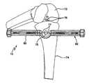
- FIG. 8is a view illustrating a clinical application of the device of FIG. 5 .
- FIGS. 1-3a suture tensioning device 10 comprised of a body 12 .
- the device 10comprises a force displacement arm 14 , which functions to fix the device 10 against the wall of a tibial tunnel 15 ( FIG. 4A ), as will be described hereinbelow.
- the force displacement arm 14is shaped to flexibly accommodate different topographies with acceptable clearance for both the final fixation implant and any installation tools. With slight modification of the design, the force displacement arm 14 maybe made removable and replaceable so that the tensioning device 10 can be either a single use device or reusable.
- a suture guide knob 16Proximal to the force displacement arm 14 is a suture guide knob 16 .
- Fasteners 18FIG. 1A ) secure the force displacement arm 14 to a force displacement tube 20 within the suture guide knob 16 .
- the device 10further comprises a plurality of suture drawers 22 .
- Pins 24are adapted for insertion through pin apertures 26 in the suture drawers 22 .
- a rotatable suture spool 28is provided, on which are disposed a plurality of thumb levers 30 .
- Fasteners 32extend through a flange 34 on the rotatable suture spool 28 , for attaching the flange 34 to a ratchet gear 36 , through apertures 38 .
- a spring collar stop 40 and a tensioner spring 42are disposed within the rotatable suture spool 28 , as shown in FIG. 1A .
- Slidable about a proximal end of the tensioner spring 42is a spring collar slide 44 .
- a pawl 46 and a ratchet torsion spring 48are provided, wherein the ratchet torsion spring 48 is disposed about an adjustment slide rod 50 .
- An adjustment lock 52 and a sliding stop 54are also provided, as shown.
- a tensioning knob 56At a proximal end of the device 10 , there is provided a tensioning knob 56 . Within the tensioning knob 56 are disposed, in cooperating relationship, an adjustment cover 58 , a washer retainer 60 , and a gauged cover plate 62 . Fasteners 64 assist in securing the adjustment cover 58 , washer retainer 60 , and gauged cover plate 62 within the tensioning knob 56 .
- a tension adjust button 66extends proximally from the adjustment cover, and is connected to an adjustment spring 68 and a spring support washer 70 , which, in turn, are operatively disposed on a proximal end of the adjustment slide rod 50 .
- the suture tensioning device 10is used in the performance of an ACL repair, of the types disclosed in U.S. Patent Application Publication No. 2006/0155287, entitled Devices, Systems, and Methods for Material Fixation, in U.S. patent application Ser. No. 11/725,981, entitled Devices, Systems, and Methods for Material Fixation, filed on Mar. 20, 2007, and in U.S. patent application Ser. No. 11/923,526, entitled Methods & Systems for Material Fixation, filed on Oct. 24, 2007. All of these prior applications are commonly assigned with the present application, and are herein expressly incorporated by reference, in their entirety.
- This particular procedureis exemplary only, as the device 10 and methods of the present invention may be used in a variety of procedures during which it is necessary or desirable to tension portions of the tissue.
- graft tendons 76are pulled proximally and become tensioned, displacement is constrained by the design to occur at the force displacement arm 14 , whose load is transferred to the force displacement tube 20 , spring collar stop 40 , and tensioner spring 42 .
- the displacement of these componentsis adjustably limited by the sliding stop 54 .
- This componentcontrols the maximum displacement of the tensioner spring by preventing further displacement once it is in contact with the spring collar stop 40 .
- the tensioner spring 42is housed within the spring collar slide 44 and is so constrained.
- the tensile force imposed on the tendons 76can be estimated by multiplying the tensioner spring constant by the displacement distance traveled by the tensioner spring 42 .
- Known values of force or a qualitative scalecan be marked on the adjustment cover 58 or the force displacement tube 20 .
- the position of the tension adjust button 66indicates the tension setting and relates the circumferential position of the sliding stop 54 to a displacement tangential along the spring collar slide 44 .
- the tensioning deviceis adjusted by depressing the tension adjust button 66 and sliding it to the desired tension force marked on the adjustment cover 58 .
- the tension adjust button 66 , adjustment spring 68 , spring support washer 70 , and adjustment slide rod 50slide along an aligned track 76 a ( FIG. 2 ) formed by the adjustment cover 58 , washer retainer 60 , and gauged cover plate 62 .
- Depressing the tension adjust button 66compresses the adjustment spring 68 , lowers the adjustment slide rod 50 , and thus disengages the adjustment lock 52 from a mated hole on the perimeter of the gauged cover plate 62 corresponding to a specific tension setting. Consequently, the pawl 46 disengages from the ratchet gear 36 .
- the adjustment slide rod 50moves circumferentially around the aligned track formed by the adjustment cover 58 , the washer retainer 60 , and the gauged cover plate 62 , it rotates the sliding stop 54 around the perimeter of the spring collar slide 44 .
- a spiral shaped cuttranslates circumferential movement of the sliding stop 54 into a tangential motion along the length of the spring collar slide 44 , thereby adjustably limiting the maximum possible displacement for the force displacement arm 14 , force displacement tube 20 , spring collar stop 40 , and thus the tensioner spring 42 .
- the tension adjust button 66is released, allowing the adjustment spring 68 to return the adjustment slide rod 50 and to re-engage the adjustment lock 52 into a mated hole of the gauged cover plate 62 , which corresponds to the desired tension setting. Simultaneously, the pawl 46 re-engages with the ratchet gear 36 assisted by the angle-chamfered teeth of the lower half of the ratchet gear 36 .
- suture 77can be loaded into the suture drawers 22 .
- the devicemay be packaged with the suture drawers in a state ready for loading, and in this configuration, any potential displacement of the force displacement arm 14 is prohibited by the interference created between lower portions of the suture drawers 22 and the suture guide knob 16 .
- Two or more suture drawers 22contain a suture slot feature which can accommodate multiple strands of a plurality of suture sizes.
- the suture guide knob 16also contains two or more suture slot features 78 ( FIG. 4B ) which provide channels for the suture strands to be guided within and removed from hindrance.
- Thumb levers 30are attached to the rotatable suture spool 28 by pins 24 . Slots in the thumb levers 30 allow movement of the pin 24 press fit through the suture drawer 22 .
- the suture drawers 22retract into a cavity within the rotatable suture spool 28 .
- the width of the suture drawers 22steps down at the location of the suture slots 78 to accommodate the width of the suture as it retracts into the cavity. Once the suture drawers 22 are retracted, the interference between the cavity walls of the rotatable suture spool 28 , the suture strands, and the suture drawers constrains the suture strands 77 from moving.
- the deviceWhen the suture strands 77 of approximately equal length have been passed through the suture guide knob 16 , after the desired tension level has been set, and loaded into the suture drawers 22 , the device is ready to tension the suture strands and soft tissue graft, to which the suture strands are connected.
- the operatorsimply grasps the suture guide knob 16 with one hand while rotating the tensioning knob 56 in a clockwise motion with the other hand.
- the deviceis held parallel to the graft tunnel.
- the tensioning knob 56is rotated until it stops. At this point, the desired tension has been reached and the sliding stop 54 has come into contact with the spring collar stop 40 , thereby prohibiting further displacement of the tensioner spring 42 .
- Tensionis achieved as the suture strands 77 , whose ends are constrained within the suture drawers 22 , wrap and accumulate around the rotatable suture spool 28 .
- the loadpropagates along the suture strands, equally tensioning each strand of the soft tissue graft 76 .
- the tensioning knob 56rotates the ratchet gear 36 and the rotatable suture spool 28 .
- the inner components of the deviceare prevented from rotating as they are fixed in relation to the suture guide knob 16 .
- a keyway internal to the spring collar slide 44 and the spring collar stop 40prohibits rotation of the spring collar slide 44 and its attached components.
- the pawl 46is therefore fixed in place relative to the suture guide knob 16 .
- the ratchet gear 36rotates clockwise around the inner components, the pawl 46 alternately moves in a clicking fashion along and opposite to the tangential vector of ratchet gear rotation.
- the ratchet torsion spring 48returns the pawl 46 to its original position between the teeth of the ratchet gear 36 .
- the ratcheting mechanism of this deviceis not limited to the description provided herein, but may also constitute similarly functional configurations utilizing a variety or a plurality of pawls, gears, teeth or grooves. it is also within the scope of the present invention to utilize a one-way (Sprag freewheel type) rotational bearing in place of the above described ratcheting mechanism.
- the soft tissue graftis first located in a tunnel drilled through the tibia, and a femoral anchor is deployed to secure a distal end of the graft in a socket drilled into the femur. Then, the proximal end of the soft tissue graft is extended proximally through the tibial tunnel and through receiving portions of a tibial anchor. Before the tibial anchor is deployed, the graft is tensioned by pulling it taut, using the device 10 .
- the devicecan be held with one hand while the joint (knee) is cycled to eliminate graft creep. Afterwards, the tension can be readjusted to a lower value for final fixation by holding the suture guide knob 16 , and while disengaging the ratchet mechanism by pressing the tension adjust button 66 , rotating the tensioning knob 56 counter-clockwise to unwind some or all suture from the suture spool 28 .
- the new tensioncan be assessed by looking at where gauged markings on the force displacement tube 20 align with the edge of the suture guide knob 16 or by releasing all tension and repeating the tensioning procedures with the newly desired value.
- the implantis positioned and an implant installation tool 79 is inserted and operated through the center of the tensioning device, as illustrated in FIGS. 4A and 4B .
- the deviceis removed from patient contact by either cutting the suture strands, thus separating the device 10 from the soft tissue grafts, or by opening the suture drawers 22 using the thumb levers 30 .
- FIGS. 5-8A second, modified embodiment of the device of the present invention is illustrated in FIGS. 5-8 .
- like elements to those illustrated in FIGS. 1-4are delineated by like reference numerals.
- the embodiment of FIG. 5differs from the FIG. 1 embodiment in that the tendon bundles 76 are tensioned laterally to the tibial tunnel 15 ( FIG. 8 ) rather than axially. Instead of pushing off of a cortical bone surface, the device 10 of FIG. 5 rests on the surrounding bone and/or tissue during the tensioning procedure.
- the device 10comprises two tensioning assemblies 80 , 82 that are symmetric about the center of the tensioner body 12 .
- a center portion 84 of the tensioner body 12is filleted with a large radius to provide a smooth transition for the tensile force to translate around the bend of the suture strands to the tendon bundles within the tibial tunnel.
- the C-shaped center portion 84 of the tensioner body 12is left open, allowing the suture strands 77 ( FIG. 8 ) to be passed over the filleted edges of the center portion of the tensioner body 12 rather than being threaded through an otherwise closed portion.
- the open center portion 84also facilitates implant insertion and installation.
- the tibial tunnel 15( FIG.
- the patient contact side of the tensioner body 12has two sliding suture cleats 88 ( FIGS. 6 and 7 ) located at each end of the device, that fixate the suture strands of the soft tissue graft for tensioning.
- Each tensioning knob 56is fixed to a force translation screw 90 .
- a threaded force translation nut 92moves linearly along the length of the tensioner body 12 .
- the tensioning nut 92is prevented from rotating relative to the tensioner body 12 by the extruded portion of the nut that slides within a channel on the top surface of the tensioner body 12 .
- the tensioning knob 56 and force translation screw 90are constrained within the cylindrical cavity of the tensioner body by the outside diameter of the tensioning knob shaft, which lies partly inside the slightly larger inner diameter of the tensioner body, allowing for rotation of the tensioning knob 56 .
- the end of the force translation screw 90 opposite to the tensioning knob 56has a notch machined into it so that it can be installed through a keyhole snap within the tensioner body 12 .
- the keyhole snapretains the opposite end of the force translation screw and allows only rotational movement of the screw.
- the force translation nut 92moves away from the center of the tensioner body and begins to compress the tensioning spring 42 , which is press fit over the force translation nut 92 and sliding suture cleat 88 , maintaining the motion of the force translation nut and the sliding suture cleat relative to one another.
- Each end of the tensioning assemblyis designed to remove any slack from the tendon bundles and suture strands by the allowance for a displacement distance beyond the combined length of the assembly of the tensioning spring 42 , force translation nut 92 , and sliding suture cleat 88 . Rotating the tensioning knob 56 will remove any slack in the tendon bundles within this allowance prior to establishing tension.
- the tensioning spring 42directs the compressive force created by the linear displacement of the translation nut to the sliding suture cleat 88 which is constrained from movement by the cleated suture strands leading into the tibial tunnel.
- Each force translation screw 90 and force translation nut 92may be threaded oppositely to one another, allowing the force translation nuts 92 to compress the tensioning springs 42 while rotating the tensioning knobs 56 in the same direction, instead of in opposing directions.
- An indicator pin or other marking on the force translation nut 92moves either underneath or relative to a slot on the sliding suture cleat/force gauge 88 which may be translucent, for purposes of reading the force indicator mark of the force translation nut 92 if the post and slot configuration is not used.
- the sliding suture cleat/force gauge 88has linear gradient markings which relate displacement of the tensioning spring 42 to force in either lbf or N.
- a typical tensioning range for each tendon bundlemay be from 0 to 30 lbf (0 to 133.45 N). However, the tension on either side of the device may be set to any value within this range by rotating the tensioning knob until the desired tension is reached.
- the design of the deviceallows tension to be set and maintained without requiring the physician to physically hold the tensioning knobs. Therefore, the device can be used by a single physician without additional assistance.
- the deviceis designed so that once tension is established, the physician can have both hands free to complete the installation of the final fixation implant.
- the final fixation implantis the tibial anchor, the femoral anchor having already been installed prior to tensioning.
- the disclosed devicepermits the physician to independently tension each tissue graft bundle to normalize stress between bundles of differing cross-sectional area, but with fewer steps, greater ease, and less time.
- the design of the tensioning deviceassists implant installation by separating and spreading the tendon bundles to the edges of the tibial tunnel, thus facilitating the process of inserting the tibial implant between the tendons.
Landscapes
- Health & Medical Sciences (AREA)
- Life Sciences & Earth Sciences (AREA)
- Surgery (AREA)
- Heart & Thoracic Surgery (AREA)
- Engineering & Computer Science (AREA)
- Biomedical Technology (AREA)
- Nuclear Medicine, Radiotherapy & Molecular Imaging (AREA)
- Medical Informatics (AREA)
- Molecular Biology (AREA)
- Animal Behavior & Ethology (AREA)
- General Health & Medical Sciences (AREA)
- Public Health (AREA)
- Veterinary Medicine (AREA)
- Surgical Instruments (AREA)
Abstract
Description
Claims (4)
Priority Applications (2)
| Application Number | Priority Date | Filing Date | Title |
|---|---|---|---|
| US11/943,566US8540734B2 (en) | 2006-11-21 | 2007-11-20 | Suture management and tensioning devices and methods for soft tissue reconstruction or bone-to-bone fixation |
| US13/014,861US20110184438A1 (en) | 2006-11-21 | 2011-01-27 | Suture management and tensioning devices and methods for soft tissue reconstruction or bone-to-bone fixation |
Applications Claiming Priority (2)
| Application Number | Priority Date | Filing Date | Title |
|---|---|---|---|
| US86053306P | 2006-11-21 | 2006-11-21 | |
| US11/943,566US8540734B2 (en) | 2006-11-21 | 2007-11-20 | Suture management and tensioning devices and methods for soft tissue reconstruction or bone-to-bone fixation |
Related Child Applications (1)
| Application Number | Title | Priority Date | Filing Date |
|---|---|---|---|
| US13/014,861DivisionUS20110184438A1 (en) | 2006-11-21 | 2011-01-27 | Suture management and tensioning devices and methods for soft tissue reconstruction or bone-to-bone fixation |
Publications (2)
| Publication Number | Publication Date |
|---|---|
| US20080154260A1 US20080154260A1 (en) | 2008-06-26 |
| US8540734B2true US8540734B2 (en) | 2013-09-24 |
Family
ID=39492967
Family Applications (2)
| Application Number | Title | Priority Date | Filing Date |
|---|---|---|---|
| US11/943,566Active2029-08-20US8540734B2 (en) | 2006-11-21 | 2007-11-20 | Suture management and tensioning devices and methods for soft tissue reconstruction or bone-to-bone fixation |
| US13/014,861AbandonedUS20110184438A1 (en) | 2006-11-21 | 2011-01-27 | Suture management and tensioning devices and methods for soft tissue reconstruction or bone-to-bone fixation |
Family Applications After (1)
| Application Number | Title | Priority Date | Filing Date |
|---|---|---|---|
| US13/014,861AbandonedUS20110184438A1 (en) | 2006-11-21 | 2011-01-27 | Suture management and tensioning devices and methods for soft tissue reconstruction or bone-to-bone fixation |
Country Status (2)
| Country | Link |
|---|---|
| US (2) | US8540734B2 (en) |
| WO (1) | WO2008070452A2 (en) |
Cited By (3)
| Publication number | Priority date | Publication date | Assignee | Title |
|---|---|---|---|---|
| WO2016164588A1 (en) | 2015-04-10 | 2016-10-13 | Board Of Suppervisors Of Louisiana State University And Agricultural And Mechanical College | Soft tissue tensioning and fixation device |
| US10265157B2 (en) | 2016-06-30 | 2019-04-23 | Medos International Sarl | Methods and devices for tensioning grafts |
| US10695048B2 (en) | 2017-03-05 | 2020-06-30 | Ryan Dean | Slack removal in suture constructs for tissue repair |
Families Citing this family (72)
| Publication number | Priority date | Publication date | Assignee | Title |
|---|---|---|---|---|
| US6488689B1 (en) | 1999-05-20 | 2002-12-03 | Aaron V. Kaplan | Methods and apparatus for transpericardial left atrial appendage closure |
| US7846168B2 (en) | 2003-10-09 | 2010-12-07 | Sentreheart, Inc. | Apparatus and method for the ligation of tissue |
| US7658751B2 (en) | 2006-09-29 | 2010-02-09 | Biomet Sports Medicine, Llc | Method for implanting soft tissue |
| US7749250B2 (en) | 2006-02-03 | 2010-07-06 | Biomet Sports Medicine, Llc | Soft tissue repair assembly and associated method |
| US9801708B2 (en) | 2004-11-05 | 2017-10-31 | Biomet Sports Medicine, Llc | Method and apparatus for coupling soft tissue to a bone |
| US8298262B2 (en) | 2006-02-03 | 2012-10-30 | Biomet Sports Medicine, Llc | Method for tissue fixation |
| US9017381B2 (en) | 2007-04-10 | 2015-04-28 | Biomet Sports Medicine, Llc | Adjustable knotless loops |
| US8137382B2 (en) | 2004-11-05 | 2012-03-20 | Biomet Sports Medicine, Llc | Method and apparatus for coupling anatomical features |
| US7905904B2 (en) | 2006-02-03 | 2011-03-15 | Biomet Sports Medicine, Llc | Soft tissue repair device and associated methods |
| US8118836B2 (en) | 2004-11-05 | 2012-02-21 | Biomet Sports Medicine, Llc | Method and apparatus for coupling soft tissue to a bone |
| US8361113B2 (en) | 2006-02-03 | 2013-01-29 | Biomet Sports Medicine, Llc | Method and apparatus for coupling soft tissue to a bone |
| US8303604B2 (en) | 2004-11-05 | 2012-11-06 | Biomet Sports Medicine, Llc | Soft tissue repair device and method |
| US8840645B2 (en) | 2004-11-05 | 2014-09-23 | Biomet Sports Medicine, Llc | Method and apparatus for coupling soft tissue to a bone |
| US8128658B2 (en) | 2004-11-05 | 2012-03-06 | Biomet Sports Medicine, Llc | Method and apparatus for coupling soft tissue to bone |
| US7909851B2 (en) | 2006-02-03 | 2011-03-22 | Biomet Sports Medicine, Llc | Soft tissue repair device and associated methods |
| US8088130B2 (en) | 2006-02-03 | 2012-01-03 | Biomet Sports Medicine, Llc | Method and apparatus for coupling soft tissue to a bone |
| US8998949B2 (en) | 2004-11-09 | 2015-04-07 | Biomet Sports Medicine, Llc | Soft tissue conduit device |
| US11259792B2 (en) | 2006-02-03 | 2022-03-01 | Biomet Sports Medicine, Llc | Method and apparatus for coupling anatomical features |
| US8597327B2 (en) | 2006-02-03 | 2013-12-03 | Biomet Manufacturing, Llc | Method and apparatus for sternal closure |
| US8652172B2 (en) | 2006-02-03 | 2014-02-18 | Biomet Sports Medicine, Llc | Flexible anchors for tissue fixation |
| US8968364B2 (en) | 2006-02-03 | 2015-03-03 | Biomet Sports Medicine, Llc | Method and apparatus for fixation of an ACL graft |
| US8574235B2 (en) | 2006-02-03 | 2013-11-05 | Biomet Sports Medicine, Llc | Method for trochanteric reattachment |
| US8562645B2 (en) | 2006-09-29 | 2013-10-22 | Biomet Sports Medicine, Llc | Method and apparatus for forming a self-locking adjustable loop |
| US9538998B2 (en) | 2006-02-03 | 2017-01-10 | Biomet Sports Medicine, Llc | Method and apparatus for fracture fixation |
| US8652171B2 (en) | 2006-02-03 | 2014-02-18 | Biomet Sports Medicine, Llc | Method and apparatus for soft tissue fixation |
| US9149267B2 (en) | 2006-02-03 | 2015-10-06 | Biomet Sports Medicine, Llc | Method and apparatus for coupling soft tissue to a bone |
| US8801783B2 (en) | 2006-09-29 | 2014-08-12 | Biomet Sports Medicine, Llc | Prosthetic ligament system for knee joint |
| US10517587B2 (en) | 2006-02-03 | 2019-12-31 | Biomet Sports Medicine, Llc | Method and apparatus for forming a self-locking adjustable loop |
| US9468433B2 (en) | 2006-02-03 | 2016-10-18 | Biomet Sports Medicine, Llc | Method and apparatus for forming a self-locking adjustable loop |
| US8562647B2 (en) | 2006-09-29 | 2013-10-22 | Biomet Sports Medicine, Llc | Method and apparatus for securing soft tissue to bone |
| US9078644B2 (en) | 2006-09-29 | 2015-07-14 | Biomet Sports Medicine, Llc | Fracture fixation device |
| US8506597B2 (en) | 2011-10-25 | 2013-08-13 | Biomet Sports Medicine, Llc | Method and apparatus for interosseous membrane reconstruction |
| US8251998B2 (en) | 2006-08-16 | 2012-08-28 | Biomet Sports Medicine, Llc | Chondral defect repair |
| US8771352B2 (en) | 2011-05-17 | 2014-07-08 | Biomet Sports Medicine, Llc | Method and apparatus for tibial fixation of an ACL graft |
| US11311287B2 (en) | 2006-02-03 | 2022-04-26 | Biomet Sports Medicine, Llc | Method for tissue fixation |
| US9918826B2 (en) | 2006-09-29 | 2018-03-20 | Biomet Sports Medicine, Llc | Scaffold for spring ligament repair |
| US8500818B2 (en) | 2006-09-29 | 2013-08-06 | Biomet Manufacturing, Llc | Knee prosthesis assembly with ligament link |
| US11259794B2 (en) | 2006-09-29 | 2022-03-01 | Biomet Sports Medicine, Llc | Method for implanting soft tissue |
| US8672969B2 (en) | 2006-09-29 | 2014-03-18 | Biomet Sports Medicine, Llc | Fracture fixation device |
| SI2142107T1 (en) | 2007-03-30 | 2013-05-31 | Sentreheart, Inc. | Devices and systems for closing the left atrial appendage |
| US8709040B2 (en) | 2008-06-26 | 2014-04-29 | Vitasynergies, Llc | Suture anchor, guide for locating a hole in a bone, and suture anchor delivery tool |
| US8282674B2 (en)* | 2008-07-18 | 2012-10-09 | Suspension Orthopaedic Solutions, Inc. | Clavicle fixation |
| US12419632B2 (en) | 2008-08-22 | 2025-09-23 | Biomet Sports Medicine, Llc | Method and apparatus for coupling anatomical features |
| US12245759B2 (en) | 2008-08-22 | 2025-03-11 | Biomet Sports Medicine, Llc | Method and apparatus for coupling soft tissue to bone |
| AU2010232589B2 (en) | 2009-04-01 | 2014-11-27 | Atricure, Inc. | Tissue ligation devices and controls therefor |
| US8343227B2 (en) | 2009-05-28 | 2013-01-01 | Biomet Manufacturing Corp. | Knee prosthesis assembly with ligament link |
| US12096928B2 (en) | 2009-05-29 | 2024-09-24 | Biomet Sports Medicine, Llc | Method and apparatus for coupling soft tissue to a bone |
| GB2474887B (en)* | 2009-10-30 | 2013-12-04 | Stats Uk Ltd | Device and method for pre-tensioning a coupling |
| AU2011241103A1 (en) | 2010-04-13 | 2012-11-08 | Sentreheart, Inc. | Methods and devices for treating atrial fibrillation |
| US12329373B2 (en) | 2011-05-02 | 2025-06-17 | Biomet Sports Medicine, Llc | Method and apparatus for soft tissue fixation |
| ES2671928T3 (en) | 2011-06-08 | 2018-06-11 | Sentreheart, Inc. | Tissue ligation devices and tension devices for them |
| US9357991B2 (en) | 2011-11-03 | 2016-06-07 | Biomet Sports Medicine, Llc | Method and apparatus for stitching tendons |
| US9381013B2 (en) | 2011-11-10 | 2016-07-05 | Biomet Sports Medicine, Llc | Method for coupling soft tissue to a bone |
| US9314241B2 (en) | 2011-11-10 | 2016-04-19 | Biomet Sports Medicine, Llc | Apparatus for coupling soft tissue to a bone |
| US9370350B2 (en) | 2011-11-10 | 2016-06-21 | Biomet Sports Medicine, Llc | Apparatus for coupling soft tissue to a bone |
| US9757119B2 (en) | 2013-03-08 | 2017-09-12 | Biomet Sports Medicine, Llc | Visual aid for identifying suture limbs arthroscopically |
| BR112015019887A2 (en) | 2013-03-12 | 2017-07-18 | Sentreheart Inc | device for closing a target tissue |
| US9918827B2 (en) | 2013-03-14 | 2018-03-20 | Biomet Sports Medicine, Llc | Scaffold for spring ligament repair |
| EP4226881A1 (en) | 2013-10-31 | 2023-08-16 | AtriCure, Inc. | Device for left atrial appendage closure |
| US10136886B2 (en) | 2013-12-20 | 2018-11-27 | Biomet Sports Medicine, Llc | Knotless soft tissue devices and techniques |
| US9615822B2 (en) | 2014-05-30 | 2017-04-11 | Biomet Sports Medicine, Llc | Insertion tools and method for soft anchor |
| US9700291B2 (en) | 2014-06-03 | 2017-07-11 | Biomet Sports Medicine, Llc | Capsule retractor |
| US10039543B2 (en) | 2014-08-22 | 2018-08-07 | Biomet Sports Medicine, Llc | Non-sliding soft anchor |
| US9955980B2 (en) | 2015-02-24 | 2018-05-01 | Biomet Sports Medicine, Llc | Anatomic soft tissue repair |
| ES2972395T3 (en) | 2015-03-24 | 2024-06-12 | Atricure Inc | Tissue ligation devices |
| US9936956B2 (en) | 2015-03-24 | 2018-04-10 | Sentreheart, Inc. | Devices and methods for left atrial appendage closure |
| US9974534B2 (en) | 2015-03-31 | 2018-05-22 | Biomet Sports Medicine, Llc | Suture anchor with soft anchor of electrospun fibers |
| EP4331509A3 (en) | 2016-02-26 | 2024-05-15 | AtriCure, Inc. | Devices for left atrial appendage closure |
| US10828146B2 (en) | 2016-08-04 | 2020-11-10 | Stryker Corporation | Instrumentation for soft tissue reconstruction |
| US11883243B2 (en) | 2019-10-31 | 2024-01-30 | Orthopediatrics Corp. | Assessment of tension between bone anchors |
| CN111658163B (en)* | 2020-05-06 | 2021-04-30 | 河南省人民医院 | Loading factor calibration device and calibration method for spinal surgery force feedback bone cone |
| WO2024184364A1 (en)* | 2023-03-06 | 2024-09-12 | Moving Spine Ag | Ligament tensioning device |
Citations (35)
| Publication number | Priority date | Publication date | Assignee | Title |
|---|---|---|---|---|
| US3507270A (en)* | 1967-07-05 | 1970-04-21 | Raymond W Ferrier | Occluder for blood vessel or flexible tube |
| US3931821A (en)* | 1972-11-24 | 1976-01-13 | Bio-Medicus, Inc. | Suture bridges |
| US4950271A (en)* | 1989-02-06 | 1990-08-21 | Regents Of The University Of Minnesota | Ligament graft apparatus and method |
| US4957498A (en) | 1987-11-05 | 1990-09-18 | Concept, Inc. | Suturing instrument |
| US5085661A (en) | 1990-10-29 | 1992-02-04 | Gerald Moss | Surgical fastener implantation device |
| US5188636A (en) | 1992-05-07 | 1993-02-23 | Ethicon, Inc. | Purse string suture instrument |
| US5281237A (en) | 1992-09-25 | 1994-01-25 | Gimpelson Richard J | Surgical stitching device and method of use |
| USRE34762E (en)* | 1988-09-19 | 1994-10-18 | Goble; E. Marlowe | Procedure for verifying isometric ligament positioning |
| US5431666A (en) | 1994-02-24 | 1995-07-11 | Lasersurge, Inc. | Surgical suture instrument |
| US5439467A (en) | 1991-12-03 | 1995-08-08 | Vesica Medical, Inc. | Suture passer |
| US5507750A (en) | 1993-09-16 | 1996-04-16 | Goble; E. Marlowe | Method and apparatus for tensioning grafts or ligaments |
| US5707395A (en)* | 1997-01-16 | 1998-01-13 | Li Medical Technologies, Inc. | Surgical fastener and method and apparatus for ligament repair |
| US5713897A (en)* | 1997-03-06 | 1998-02-03 | Goble; E. Marlowe | Anterior cruciate ligament tensioning device and method for its use |
| US5788697A (en)* | 1994-02-24 | 1998-08-04 | Pioneer Laboratories, Inc. | Cable tensioning device |
| US5810848A (en)* | 1996-08-21 | 1998-09-22 | Hayhurst; John O. | Suturing system |
| US5846254A (en) | 1997-04-08 | 1998-12-08 | Ethicon Endo-Surgery, Inc. | Surgical instrument for forming a knot |
| US5980473A (en)* | 1997-04-08 | 1999-11-09 | Barnes-Jewish Hospital | Surgical apparatus for determining ligament and tendon tension |
| US6015428A (en)* | 1997-06-03 | 2000-01-18 | Anthony C. Pagedas | Integrally formed suture and suture lock |
| US6171310B1 (en)* | 1998-04-01 | 2001-01-09 | Aesculap Ag & Co. Kg | Device and method for handling an implant covering a bone tunnel |
| US20020091391A1 (en)* | 1998-01-26 | 2002-07-11 | Orthodyne, Inc. | Tissue anchoring system and method |
| US20020120280A1 (en) | 1999-12-21 | 2002-08-29 | Securos, Inc. | Crimping device for cranial cruciate ligament stabilization |
| US6533795B1 (en) | 2000-04-11 | 2003-03-18 | Opus Medical, Inc | Dual function suturing apparatus and method |
| US6547778B1 (en)* | 2000-07-21 | 2003-04-15 | Joseph H. Sklar | Graft ligament strand tensioner |
| US6551330B1 (en) | 2000-09-21 | 2003-04-22 | Opus Medical, Inc. | Linear suturing apparatus and methods |
| US20030208210A1 (en)* | 2002-05-01 | 2003-11-06 | Dreyfuss Peter J. | Suture tensioning device |
| US20040068267A1 (en) | 2000-06-27 | 2004-04-08 | Fraser Harvie | Surgical procedures and instruments |
| US20040098050A1 (en) | 2002-11-19 | 2004-05-20 | Opus Medical, Inc. | Devices and methods for repairing soft tissue |
| US20040122456A1 (en)* | 2002-12-11 | 2004-06-24 | Saadat Vahid C. | Methods and apparatus for gastric reduction |
| US6770084B1 (en) | 2002-06-26 | 2004-08-03 | Opus Medical, Inc. | Suture capture device |
| US20050027226A1 (en) | 2003-05-06 | 2005-02-03 | Centerpulse Orthopedics Ltd. | Traction apparatus |
| US20050049597A1 (en)* | 2003-08-29 | 2005-03-03 | West Hugh S. | Suture separation and organization devices for use with graft tensioning device |
| US7371244B2 (en)* | 2003-08-25 | 2008-05-13 | Ethicon, Inc. | Deployment apparatus for suture anchoring device |
| US7442172B2 (en)* | 2002-08-29 | 2008-10-28 | Zimmer, Inc. | Ligament tension gauge |
| US7678135B2 (en)* | 2004-06-09 | 2010-03-16 | Usgi Medical, Inc. | Compressible tissue anchor assemblies |
| US7887564B2 (en)* | 2003-01-25 | 2011-02-15 | Boehringer Technologies, L.P. | Method for treating a wound |
Family Cites Families (1)
| Publication number | Priority date | Publication date | Assignee | Title |
|---|---|---|---|---|
| WO1995032669A1 (en)* | 1994-06-01 | 1995-12-07 | Perclose, Inc. | Apparatus and method for advancing surgical knots |
- 2007
- 2007-11-20USUS11/943,566patent/US8540734B2/enactiveActive
- 2007-11-20WOPCT/US2007/085317patent/WO2008070452A2/enactiveApplication Filing
- 2011
- 2011-01-27USUS13/014,861patent/US20110184438A1/ennot_activeAbandoned
Patent Citations (38)
| Publication number | Priority date | Publication date | Assignee | Title |
|---|---|---|---|---|
| US3507270A (en)* | 1967-07-05 | 1970-04-21 | Raymond W Ferrier | Occluder for blood vessel or flexible tube |
| US3931821A (en)* | 1972-11-24 | 1976-01-13 | Bio-Medicus, Inc. | Suture bridges |
| US4957498A (en) | 1987-11-05 | 1990-09-18 | Concept, Inc. | Suturing instrument |
| USRE34762E (en)* | 1988-09-19 | 1994-10-18 | Goble; E. Marlowe | Procedure for verifying isometric ligament positioning |
| US4950271A (en)* | 1989-02-06 | 1990-08-21 | Regents Of The University Of Minnesota | Ligament graft apparatus and method |
| US5085661A (en) | 1990-10-29 | 1992-02-04 | Gerald Moss | Surgical fastener implantation device |
| US5439467A (en) | 1991-12-03 | 1995-08-08 | Vesica Medical, Inc. | Suture passer |
| US5188636A (en) | 1992-05-07 | 1993-02-23 | Ethicon, Inc. | Purse string suture instrument |
| US5281237A (en) | 1992-09-25 | 1994-01-25 | Gimpelson Richard J | Surgical stitching device and method of use |
| US5507750A (en) | 1993-09-16 | 1996-04-16 | Goble; E. Marlowe | Method and apparatus for tensioning grafts or ligaments |
| US5788697A (en)* | 1994-02-24 | 1998-08-04 | Pioneer Laboratories, Inc. | Cable tensioning device |
| US5431666A (en) | 1994-02-24 | 1995-07-11 | Lasersurge, Inc. | Surgical suture instrument |
| US5810848A (en)* | 1996-08-21 | 1998-09-22 | Hayhurst; John O. | Suturing system |
| US5707395A (en)* | 1997-01-16 | 1998-01-13 | Li Medical Technologies, Inc. | Surgical fastener and method and apparatus for ligament repair |
| US5713897A (en)* | 1997-03-06 | 1998-02-03 | Goble; E. Marlowe | Anterior cruciate ligament tensioning device and method for its use |
| US5846254A (en) | 1997-04-08 | 1998-12-08 | Ethicon Endo-Surgery, Inc. | Surgical instrument for forming a knot |
| US5980473A (en)* | 1997-04-08 | 1999-11-09 | Barnes-Jewish Hospital | Surgical apparatus for determining ligament and tendon tension |
| US6015428A (en)* | 1997-06-03 | 2000-01-18 | Anthony C. Pagedas | Integrally formed suture and suture lock |
| US6761722B2 (en)* | 1998-01-26 | 2004-07-13 | Orthodyne, Inc. | Tissue anchoring system and method |
| US20020091391A1 (en)* | 1998-01-26 | 2002-07-11 | Orthodyne, Inc. | Tissue anchoring system and method |
| US6171310B1 (en)* | 1998-04-01 | 2001-01-09 | Aesculap Ag & Co. Kg | Device and method for handling an implant covering a bone tunnel |
| US20020120280A1 (en) | 1999-12-21 | 2002-08-29 | Securos, Inc. | Crimping device for cranial cruciate ligament stabilization |
| US6533795B1 (en) | 2000-04-11 | 2003-03-18 | Opus Medical, Inc | Dual function suturing apparatus and method |
| US20040068267A1 (en) | 2000-06-27 | 2004-04-08 | Fraser Harvie | Surgical procedures and instruments |
| US6547778B1 (en)* | 2000-07-21 | 2003-04-15 | Joseph H. Sklar | Graft ligament strand tensioner |
| US20030176920A1 (en)* | 2000-07-21 | 2003-09-18 | Sklar Joseph H. | Graft ligament strand tensioner |
| US6551330B1 (en) | 2000-09-21 | 2003-04-22 | Opus Medical, Inc. | Linear suturing apparatus and methods |
| US20030208210A1 (en)* | 2002-05-01 | 2003-11-06 | Dreyfuss Peter J. | Suture tensioning device |
| US6770084B1 (en) | 2002-06-26 | 2004-08-03 | Opus Medical, Inc. | Suture capture device |
| US7442172B2 (en)* | 2002-08-29 | 2008-10-28 | Zimmer, Inc. | Ligament tension gauge |
| US20040098050A1 (en) | 2002-11-19 | 2004-05-20 | Opus Medical, Inc. | Devices and methods for repairing soft tissue |
| US20040122456A1 (en)* | 2002-12-11 | 2004-06-24 | Saadat Vahid C. | Methods and apparatus for gastric reduction |
| US7887564B2 (en)* | 2003-01-25 | 2011-02-15 | Boehringer Technologies, L.P. | Method for treating a wound |
| US20050027226A1 (en) | 2003-05-06 | 2005-02-03 | Centerpulse Orthopedics Ltd. | Traction apparatus |
| US7371244B2 (en)* | 2003-08-25 | 2008-05-13 | Ethicon, Inc. | Deployment apparatus for suture anchoring device |
| US20050049597A1 (en)* | 2003-08-29 | 2005-03-03 | West Hugh S. | Suture separation and organization devices for use with graft tensioning device |
| US7686810B2 (en)* | 2003-08-29 | 2010-03-30 | Hs West Investments, Llc | Suture separation and organization devices for use with graft tensioning device |
| US7678135B2 (en)* | 2004-06-09 | 2010-03-16 | Usgi Medical, Inc. | Compressible tissue anchor assemblies |
Non-Patent Citations (1)
| Title |
|---|
| International Search Report, Jun. 25, 2008, corresponding to PCT Application No. PCT/US07/85317; Written Opinion of the International Searching Authority, Jun. 25, 2008, corresponding to PCT Application No. PCT/US07/85317. |
Cited By (6)
| Publication number | Priority date | Publication date | Assignee | Title |
|---|---|---|---|---|
| WO2016164588A1 (en) | 2015-04-10 | 2016-10-13 | Board Of Suppervisors Of Louisiana State University And Agricultural And Mechanical College | Soft tissue tensioning and fixation device |
| US9872760B2 (en) | 2015-04-10 | 2018-01-23 | Board Of Supervisors Of Louisiana State University And Agricultural And Mechanical College | Soft tissue tensioning and fixation device |
| US10265157B2 (en) | 2016-06-30 | 2019-04-23 | Medos International Sarl | Methods and devices for tensioning grafts |
| US11253349B2 (en) | 2016-06-30 | 2022-02-22 | Medos International Sarl | Methods and devices for tensioning grafts |
| US12178697B2 (en) | 2016-06-30 | 2024-12-31 | Medos International Sarl | Methods and devices for tensioning grafts |
| US10695048B2 (en) | 2017-03-05 | 2020-06-30 | Ryan Dean | Slack removal in suture constructs for tissue repair |
Also Published As
| Publication number | Publication date |
|---|---|
| WO2008070452A2 (en) | 2008-06-12 |
| WO2008070452A3 (en) | 2008-10-16 |
| US20110184438A1 (en) | 2011-07-28 |
| US20080154260A1 (en) | 2008-06-26 |
Similar Documents
| Publication | Publication Date | Title |
|---|---|---|
| US8540734B2 (en) | Suture management and tensioning devices and methods for soft tissue reconstruction or bone-to-bone fixation | |
| EP1297798B1 (en) | Variable graft tensioner | |
| JP5043109B2 (en) | Transplant ligament strand tensioner | |
| US11065103B2 (en) | Method and apparatus for fixation of an ACL graft | |
| US9216078B2 (en) | Method and apparatus for tibial fixation of an ACL graft | |
| EP2709557B1 (en) | Apparatus for fixation of an acl graft | |
| US6695852B2 (en) | Tension tools for tension band clip | |
| US7740657B2 (en) | Soft tissue sock enhancement devices | |
| US8984720B2 (en) | Tensioning instrument and method | |
| US8858565B1 (en) | Inserter for soft tissue or bone-to-bone fixation device and methods | |
| US20040024456A1 (en) | Sheaths for implantable fixation devices | |
| AU2007231608A1 (en) | Methods and devices for ligament repair | |
| US20250064446A1 (en) | Joint repair augmentation | |
| US11406399B2 (en) | Multi-barrel drill guide and anchor deployment assembly | |
| US20230320838A1 (en) | Apparatus and method for implanting bone anchor under controlled tension | |
| US12279945B2 (en) | Dynamic ligament repair device | |
| US20240415545A1 (en) | Stabilization implant systems and related methods | |
| US20210361408A1 (en) | Medical device for tensioning of ligaments adjustable to different anatomical locations |
Legal Events
| Date | Code | Title | Description |
|---|---|---|---|
| AS | Assignment | Owner name:CAYENNE MEDICAL, INC., ARIZONA Free format text:ASSIGNMENT OF ASSIGNORS INTEREST;ASSIGNOR:HOOF, JORDAN A.;REEL/FRAME:021216/0195 Effective date:20080215 | |
| AS | Assignment | Owner name:VENTURE LENDING & LEASING V, INC., CALIFORNIA Free format text:SECURITY AGREEMENT;ASSIGNOR:CAYENNE MEDICAL, INC.;REEL/FRAME:025626/0518 Effective date:20110112 Owner name:VENTURE LENDING & LEASING VI, INC., CALIFORNIA Free format text:SECURITY AGREEMENT;ASSIGNOR:CAYENNE MEDICAL, INC.;REEL/FRAME:025626/0518 Effective date:20110112 | |
| AS | Assignment | Owner name:CAYENNE MEDICAL, INC., ARIZONA Free format text:RELEASE BY SECURED PARTY;ASSIGNORS:VENTURE LENDING & LEASING V, INC.;VENTURE LENDING & LEASING VI, INC.;REEL/FRAME:028292/0812 Effective date:20120525 | |
| STCF | Information on status: patent grant | Free format text:PATENTED CASE | |
| AS | Assignment | Owner name:VENTURE LENDING & LEASING VI, INC., CALIFORNIA Free format text:SECURITY INTEREST;ASSIGNOR:CAYENNE MEDICAL, INC.;REEL/FRAME:032841/0715 Effective date:20140211 Owner name:VENTURE LENDING & LEASING VII, INC., CALIFORNIA Free format text:SECURITY INTEREST;ASSIGNOR:CAYENNE MEDICAL, INC.;REEL/FRAME:032841/0715 Effective date:20140211 | |
| AS | Assignment | Owner name:CAYENNE MEDICAL, INC., ARIZONA Free format text:RELEASE BY SECURED PARTY;ASSIGNORS:VENTURE LENDING & LEASING VI, INC.;VENTURE LENDING & LEASING VII, INC.;REEL/FRAME:036071/0863 Effective date:20150519 | |
| FPAY | Fee payment | Year of fee payment:4 | |
| MAFP | Maintenance fee payment | Free format text:PAYMENT OF MAINTENANCE FEE, 8TH YR, SMALL ENTITY (ORIGINAL EVENT CODE: M2552); ENTITY STATUS OF PATENT OWNER: SMALL ENTITY Year of fee payment:8 | |
| MAFP | Maintenance fee payment | Free format text:PAYMENT OF MAINTENANCE FEE, 12TH YR, SMALL ENTITY (ORIGINAL EVENT CODE: M2553); ENTITY STATUS OF PATENT OWNER: SMALL ENTITY Year of fee payment:12 |