US8540035B2 - Extendable cutting tools for use in a wellbore - Google Patents
Extendable cutting tools for use in a wellboreDownload PDFInfo
- Publication number
- US8540035B2 US8540035B2US12/616,107US61610709AUS8540035B2US 8540035 B2US8540035 B2US 8540035B2US 61610709 AUS61610709 AUS 61610709AUS 8540035 B2US8540035 B2US 8540035B2
- Authority
- US
- United States
- Prior art keywords
- piston
- arm
- tool
- retracted position
- tubular body
- Prior art date
- Legal status (The legal status is an assumption and is not a legal conclusion. Google has not performed a legal analysis and makes no representation as to the accuracy of the status listed.)
- Active, expires
Links
Images


Classifications
- E—FIXED CONSTRUCTIONS
- E21—EARTH OR ROCK DRILLING; MINING
- E21B—EARTH OR ROCK DRILLING; OBTAINING OIL, GAS, WATER, SOLUBLE OR MELTABLE MATERIALS OR A SLURRY OF MINERALS FROM WELLS
- E21B10/00—Drill bits
- E21B10/26—Drill bits with leading portion, i.e. drill bits with a pilot cutter; Drill bits for enlarging the borehole, e.g. reamers
- E21B10/32—Drill bits with leading portion, i.e. drill bits with a pilot cutter; Drill bits for enlarging the borehole, e.g. reamers with expansible cutting tools
- E—FIXED CONSTRUCTIONS
- E21—EARTH OR ROCK DRILLING; MINING
- E21B—EARTH OR ROCK DRILLING; OBTAINING OIL, GAS, WATER, SOLUBLE OR MELTABLE MATERIALS OR A SLURRY OF MINERALS FROM WELLS
- E21B23/00—Apparatus for displacing, setting, locking, releasing or removing tools, packers or the like in boreholes or wells
- E21B23/04—Apparatus for displacing, setting, locking, releasing or removing tools, packers or the like in boreholes or wells operated by fluid means, e.g. actuated by explosion
- E21B23/0421—Apparatus for displacing, setting, locking, releasing or removing tools, packers or the like in boreholes or wells operated by fluid means, e.g. actuated by explosion using multiple hydraulically interconnected pistons
- E—FIXED CONSTRUCTIONS
- E21—EARTH OR ROCK DRILLING; MINING
- E21B—EARTH OR ROCK DRILLING; OBTAINING OIL, GAS, WATER, SOLUBLE OR MELTABLE MATERIALS OR A SLURRY OF MINERALS FROM WELLS
- E21B47/00—Survey of boreholes or wells
- E21B47/12—Means for transmitting measuring-signals or control signals from the well to the surface, or from the surface to the well, e.g. for logging while drilling
- E21B47/13—Means for transmitting measuring-signals or control signals from the well to the surface, or from the surface to the well, e.g. for logging while drilling by electromagnetic energy, e.g. radio frequency
- E—FIXED CONSTRUCTIONS
- E21—EARTH OR ROCK DRILLING; MINING
- E21B—EARTH OR ROCK DRILLING; OBTAINING OIL, GAS, WATER, SOLUBLE OR MELTABLE MATERIALS OR A SLURRY OF MINERALS FROM WELLS
- E21B47/00—Survey of boreholes or wells
- E21B47/12—Means for transmitting measuring-signals or control signals from the well to the surface, or from the surface to the well, e.g. for logging while drilling
- E21B47/14—Means for transmitting measuring-signals or control signals from the well to the surface, or from the surface to the well, e.g. for logging while drilling using acoustic waves
- E—FIXED CONSTRUCTIONS
- E21—EARTH OR ROCK DRILLING; MINING
- E21B—EARTH OR ROCK DRILLING; OBTAINING OIL, GAS, WATER, SOLUBLE OR MELTABLE MATERIALS OR A SLURRY OF MINERALS FROM WELLS
- E21B7/00—Special methods or apparatus for drilling
- E21B7/28—Enlarging drilled holes, e.g. by counterboring
Definitions
- Embodiments of the present inventiongenerally relate to extendable cutting tools for use in a wellbore.
- a wellboreis formed to access hydrocarbon bearing formations, e.g. crude oil and/or natural gas, by the use of drilling. Drilling is accomplished by utilizing a drill bit that is mounted on the end of a tubular string, such as a drill string. To drill within the wellbore to a predetermined depth, the drill string is often rotated by a top drive or rotary table on a surface platform or rig, and/or by a downhole motor mounted towards the lower end of the drill string. After drilling to a predetermined depth, the drill string and drill bit are removed and a section of casing is lowered into the wellbore. An annulus is thus formed between the string of casing and the formation. The casing string is temporarily hung from the surface of the well.
- the casing stringis cemented into the wellbore by circulating cement into the annulus defined between the outer wall of the casing and the borehole.
- the combination of cement and casingstrengthens the wellbore and facilitates the isolation of certain areas of the formation behind the casing for the production of hydrocarbons.
- the wellis drilled to a first designated depth with a drill bit on a drill string.
- the drill stringis removed.
- a first string of casingis then run into the wellbore and set in the drilled out portion of the wellbore, and cement is circulated into the annulus behind the casing string.
- the wellis drilled to a second designated depth, and a second string of casing or liner, is run into the drilled out portion of the wellbore. If the second string is a liner string, the liner is set at a depth such that the upper portion of the second string of casing overlaps the lower portion of the first string of casing.
- the liner stringmay then be fixed, or “hung” off of the existing casing by the use of slips which utilize slip members and cones to frictionally affix the new string of liner in the wellbore.
- the second casing or liner stringis then cemented. This process is typically repeated with additional casing or liner strings until the well has been drilled to total depth. In this manner, wells are typically formed with two or more strings of casing/liner of an ever-decreasing diameter.
- the casing/liner stringsbecome progressively smaller in diameter to fit within the previous casing/liner string.
- the drill bit for drilling to the next predetermined depthmust thus become progressively smaller as the diameter of each casing/liner string decreases. Therefore, multiple drill bits of different sizes are ordinarily necessary for drilling operations.
- the flow area for the production of oil and gasis reduced. Therefore, to increase the annulus for the cementing operation, and to increase the production flow area, it is often desirable to enlarge the borehole below the terminal end of the previously cased/lined borehole.
- Underreamersmay include a plurality of arms which may move between a retracted position and an extended position. The underreamer may be passed through the casing/liner, behind the pilot bit when the arms are retracted. After passing through the casing, the arms may be extended in order to enlarge the wellbore below the casing.
- a tool for use in a wellboreincludes a tubular body having a bore therethrough, an opening through a wall thereof, and a connector at each longitudinal end thereof; and an arm.
- the armis pivotally connected to a first piston and rotationally coupled to the body.
- the armis disposed in the opening in a retracted position, and is movable to an extended position where an outer surface of the arm extends outward past an outer surface of the body.
- the toolfurther includes the first piston.
- the first pistonis disposed in the body bore, has a bore therethrough, and is operable to move the arm from the retracted position to the extended position in response to fluid pressure in the piston bore exceeding fluid pressure in the opening.
- the toolfurther includes a lock operable to retain the first piston in the retracted position; and a second piston operably coupled to the lock.
- a tool for use in a wellborein another embodiment, includes a tubular body having a bore therethrough and an opening through a wall thereof; and an arm.
- the armis pivotally connected to the body or a first piston, disposed in the opening in a retracted position, and movable to an extended position where an outer surface of the arm extends outward past an outer surface of the body.
- the first pistonis disposed in the body bore, has a bore therethrough, and is operable to move the arm from the retracted position to the extended position in response to fluid pressure in the piston bore exceeding fluid pressure in the opening.
- the toolfurther includes a lock operable to retain the piston in the retracted position; and a controller operable to release the lock in response to receiving an instruction signal.
- the toolfurther includes a tachometer for measuring an angular speed of the body and in communication with the controller, wherein the controller is operable to receive the instruction signal using the tachometer.
- the toolfurther includes an antenna in communication with the controller, wherein the controller is operable to receive the instruction signal using the antenna.
- the toolfurther includes a pressure sensor or flow sensor, wherein the controller is operable to receive the instruction signal using the pressure or flow sensor.
- the toolfurther includes a mud pulser in communication with the controller, wherein the controller is operable to modulate the mud pulser to send a signal to the surface.
- the toolfurther includes a tachometer for measuring an angular speed of the body; and a pressure sensor or flow sensor and in communication with the controller, wherein the controller is operable to receive the instruction signal using either the tachometer or the pressure or flow sensor.
- the toolfurther includes a sensor operable to measure a position of the first piston and in communication with the controller.
- Each of the body and the armmay have a shoulder and the shoulders may be engaged in the extended position. Each shoulder may be radially inclined to create a radially inward component of a normal reaction force between the arm and the body.
- the controlleris operable to re-engage the lock in response to receiving a second instruction signal. The controller may also be operable to re-engage the lock when the arm is an intermediate position between the retracted and extended position.
- the toolfurther includes an actuator in communication with the controller, wherein the controller is operable to move the first piston toward the retracted position using the actuator, and the actuator is operable to move the first piston when fluid is being injected through the tool.
- the toolmay be used in a method including running a drilling assembly into the wellbore through a casing string, the drilling assembly comprising a tubular string, the tool, and a drill bit; injecting drilling fluid through the tubular string and rotating the drill bit, wherein the tool remains locked in the retracted position; sending an instruction signal from the surface to the tool, thereby extending the arm; and drilling and reaming the wellbore using the drill bit and the extended tool.
- the drilling assemblymay further include a stabilizer and the instruction signal may also extend an arm of the stabilizer.
- the methodmay further include running an actuator through the tubular string to the tool using wireline or slickline; and retracting the arm using the actuator.
- a tool for use in a wellborein another embodiment, includes a tubular body having a bore therethrough and an opening through a wall thereof; and an arm.
- the armis disposed in the opening in a retracted position, and movable to an extended position where an outer surface of the arm extends outward past an outer surface of the body.
- the toolfurther includes a first piston disposed in the body bore, having a bore therethrough, and operable to move the arm from the retracted position to the extended position in response to fluid pressure in the first piston bore exceeding fluid pressure in the opening.
- the toolfurther includes a lock operable to retain the first piston in the retracted position; a second piston operable to release the lock in response to fluid pressure; an actuator operable to move the piston and release the lock; and a controller operable to receive an instruction signal and operate the actuator.
- a method of drilling a wellboreincludes running a drilling assembly into the wellbore through a casing string.
- the drilling assemblyincludes a tubular string, upper and lower underreamers, and a drill bit.
- the methodfurther includes injecting drilling fluid through the tubular string and rotating the drill bit, wherein the underreamers remain locked in the retracted position; sending an instruction signal to the underreamers via modulation of a rotational speed of the drilling assembly, modulation of a drilling fluid injection rate, or modulation of a drilling fluid pressure, thereby extending one of the underreamers; and drilling and reaming the wellbore the drill bit and the extended underreamer; sending an instruction signal to the underreamers via modulation of a rotational speed of the drilling assembly, modulation of a drilling fluid injection rate, or modulation of a drilling fluid pressure, thereby extending the other of the underreamers; and drilling and reaming the wellbore using the drill bit and the extended other underreamer.
- a method of drilling a wellboreincludes running a drilling assembly into the wellbore through a casing string, the drilling assembly including a tubular string, upper and lower underreamers, and a drill bit; injecting drilling fluid through the tubular string and rotating the drill bit, wherein the underreamers remain locked in the retracted position; sending an instruction signal to one of the underreamers, thereby extending one of the underreamers; drilling and reaming the wellbore the drill bit and the extended underreamer; pumping a closure member to the other of the underreamers or injecting drilling fluid through the drilling assembly at a flow rate greater than or equal to a predetermined flow rate, thereby extending the other of the underreamers; and drilling and reaming the wellbore using the drill bit and the extended other underreamer.
- a method of drilling a wellboreincludes: running a drilling assembly into the wellbore through a casing string.
- the drilling assemblyincludes a tubular string, upper and lower underreamers, and a drill bit.
- the methodfurther includes extending one of the underreamers; drilling and reaming a first geological formation using the drill bit and the extended underreamer; extending the other underreamer; and drilling and reaming a second geological formation using the drill bit and the extended other underreamer.
- a cutter for use in a wellboreincludes: a tubular body having a bore therethrough and an opening through a wall thereof; an arm disposed in the opening in a retracted position and movable to an extended position where an outer surface of the arm extends outward past an outer surface of the body; and a piston.
- the pistonis disposed in the body bore, has a bore therethrough, and is operable to move the arm from the retracted position to the extended position in response to fluid pressure in the piston bore exceeding fluid pressure in the opening.
- the cutterfurther includes a controller operable to: receive a position signal from the surface, and move to a set position in response to the signal.
- a cutter for use in a wellboreincludes a tubular body having a bore therethrough and an opening through a wall thereof; an arm disposed in the opening in a retracted position and movable to an extended position where an outer surface of the arm extends outward past an outer surface of the body; and a mandrel.
- the mandrelis disposed in the body bore, having a bore therethrough, and operable to move the arm from the retracted position to the extended position.
- the cutterfurther includes a controller operable to: receive a position signal from the surface, and move the mandrel to a set position in response to the position signal, thereby at least partially extending the arm.
- a method of cutting or milling a tubular cemented to a wellboreincludes deploying a cutting assembly into the wellbore, the cutting assembly comprising a workstring and a cutter; sending an instruction signal to the cutter, thereby extending one or more arms of the cutter; and rotating the cutter, thereby milling or cutting the tubular.
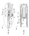
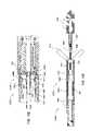
- FIGS. 1A and 1Bare cross-sections of an underreamer in a retracted and extended position, respectively, according to one embodiment of the present invention.
- FIG. 1Cis an isometric view of arms of the underreamer.
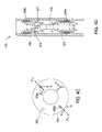
- FIGS. 2A and 2Bare cross-sections of a mechanical control module connected to the underreamer in a retracted and extended position, respectively, according to another embodiment of the present invention.
- FIG. 3illustrates an electro-hydraulic control module for use with the underreamer, according to another embodiment of the present invention.
- FIG. 4illustrates a telemetry sub for use with the control module, according to another embodiment of the present invention.
- FIG. 4Aillustrates an electronics package of the telemetry sub.
- FIG. 4Billustrates an active RFID tag and a passive RFID tag for use with the telemetry sub.
- FIG. 4Cillustrates accelerometers of the telemetry sub.
- FIG. 4Dillustrates a mud pulser of the telemetry sub.
- FIGS. 5A and 5Billustrate a drilling system and method utilizing the underreamer, according to another embodiment of the present invention.
- FIG. 6Aillustrates an alternative electro-hydraulic control module for use with the underreamer, according to another embodiment of the present invention.
- FIG. 6Billustrates another alternative electro-hydraulic control module for use with the underreamer, according to another embodiment of the present invention.
- FIG. 6Cillustrates an alternative electro-mechanical control module for use with the underreamer, according to another embodiment of the present invention.
- FIG. 7Aillustrates a bottom hole assembly (BHA) including dual underreamers, according to another embodiment of the present invention.
- FIGS. 7B and 7Cillustrates an operating sequence for the dual underreamers.
- FIG. 8illustrates an alternative dual underreamer BHA, according to another embodiment of the present invention.
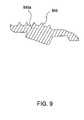
- FIG. 9illustrates an underreamer arm configured for soft formations, according to another embodiment of the present invention.
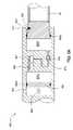
- FIG. 10Ais a cross section of a casing cutter in a retracted position, according to another embodiment of the present invention.
- FIG. 10Bis a cross section of the casing cutter in an extended position.
- FIG. 10Cis an enlargement of a portion of FIG. 10A .
- FIG. 10Dis a cross section of a portion of an alternative casing cutter.
- FIG. 10Eis a cross section of a portion of an alternative casing cutter.
- FIG. 10Fis a cross section of an alternative casing cutter in an extended position.
- FIG. 11Ais a cross section of a section mill in a retracted position, according to another embodiment of the present invention.
- FIG. 11Bis an enlargement of a portion of FIG. 11A .
- FIGS. 12A-12Care cross-sections of a mechanical control module in a first retracted, extended, and second retracted position, respectively, according to another embodiment of the present invention.
- FIGS. 13A and 13Bare cross-sections of an underreamer in an extended and second retracted position, respectively, according to another embodiment of the present invention.
- FIGS. 14A and 14Bare cross-sections of a hydraulic control module in a retracted and extended position, respectively, according to another embodiment of the present invention.
- FIGS. 1A and 1Bare cross-sections of an underreamer 100 in a retracted and extended position, respectively, according to one embodiment of the present invention.
- the underreamer 100may include a body 5 , an adapter 7 , a piston 10 , one or more seal sleeves 15 u,l , a mandrel 20 , and one or more arms 50 a,b (see FIG. 1C for 50 b ).
- the body 5may be tubular and have a longitudinal bore formed therethrough. Each longitudinal end 5 a,b of the body 5 may be threaded for longitudinal and rotational coupling to other members, such as a control module 200 at 5 a and the adapter 7 at 5 b .
- the body 5may have an opening 5 o formed through a wall thereof for each arm 50 a,b .
- the body 5may also have a chamber formed therein at least partially defined by shoulder 5 s for receiving a lower end of the piston 10 and the lower seal sleeve 15 l .
- the body 5may include an actuation profile 5 p formed in a surface thereof for each arm 50 a,b adjacent the opening 5 o .
- An end of the adapter 7 distal from the body(not shown) may be threaded for longitudinal and rotational coupling to another member of a bottomhole assembly (BHA).
- the piston 10may be a tubular, have a longitudinal bore formed therethrough, and may be disposed in the body bore.
- the piston 10may have a flow port 10 p formed through a wall thereof corresponding to each arm 50 a,b .
- a nozzle 14may be disposed in each port 10 p and made from an erosion resistant material, such as a metal, alloy, ceramic, or cermet.
- the mandrel 20may be tubular, have a longitudinal bore formed therethrough, and be longitudinally coupled to the lower seal sleeve 15 l by a threaded connection.
- the lower seal sleeve 15 lmay be longitudinally coupled to the body 5 by being disposed between the shoulder 5 s and a top of the adapter 7 .
- the upper seal sleeve 15 umay be longitudinally coupled to the body 5 by a threaded connection.
- Each arm 50 a,bmay be movable between an extended and a retracted position and may initially be disposed in the opening 5 o in the retracted position.
- Each arm 50 a,bmay be pivoted to the piston 10 by a fastener 25 .
- Each arm 50 a,bmay be biased radially inward by a torsion spring (not shown) disposed around the fastener 25 .
- a surface of the body 5 defining each opening 5 omay serve as a rotational stop for a respective blade 50 a,b , thereby rotationally coupling the blade 50 a,b to the body 5 (in both the extended and retracted positions).
- Each arm 50 a,bmay include an actuation profile 50 p formed in an inner surface thereof corresponding to the profile 5 p . Movement of each arm 50 a,b along the actuation profile 5 p may force the arm radially outward from the retracted position to the extended position.
- Each actuation profile 5 p , 50 pmay include a shoulder. The shoulders may be inclined relative to a radial axis of the body 5 in order to secure each arm 50 a,b to the body in the extended position so that the arms do not chatter or vibrate during reaming.
- the inclination of the shouldersmay create a radial component of the normal reaction force between each arm and the body 5 , thereby holding each arm 50 a,b radially inward in the extended position.
- the actuation profiles 5 p , 50 pmay each be circumferentially inclined (not shown) to retain the arms 50 a,b against a trailing surface of the body defining the opening 5 o to further ensure against chatter or vibration.
- the underreamer 100may be fluid operated by drilling fluid injected through the drill string being at a high pressure and drilling fluid and cuttings, collectively returns, flowing to the surface via the annulus being at a lower pressure.
- a first surface 10 h of the piston 10may be isolated from a second surface 10 l of the piston 10 by a lower seal 12 l disposed between an outer surface of the piston 10 and an inner surface of the lower seal sleeve 15 l .
- the lower seal 12 lmay be a ring or stack of seals, such as chevron seals, and made from a polymer, such as an elastomer.
- the high pressuremay act on the first surface 10 h of the piston via one or more ports formed through a wall of the mandrel 20 and the low pressure may act on the second surface 10 l of the piston 10 via fluid communication with the openings 5 o , thereby creating a net actuation force and moving the arms 50 a,b from the retracted position to the extended position.
- An upper seal 12 umay be disposed between the upper seal sleeve 15 u and an outer surface of the piston 10 to isolate the openings 5 o .
- the upper seal 12 umay be a ring or stack of seals, such as chevron seals, and made from a polymer, such as an elastomer.
- Various other seals, such as o-ringsmay be disposed throughout the underreamer 100 .
- the piston ports 10 pmay be closed by the mandrel 20 and straddled by seals, such as o-rings, to isolate the ports from the piston bore.
- the flow ports 10 pmay be exposed to the piston bore, thereby discharging a portion of the drilling fluid into the annulus to cool and lubricate the arms 50 a,b and carry cuttings to the surface. This exposure of the flow ports 10 p may result in a drop in upstream pressure, thereby providing an indication at the surface that the arms 50 a,b are extended.
- FIG. 1Cis an isometric view of the arms 50 a,b .
- An outer surface of each arm 50 a,bmay form one or more blades 51 a,b and a stabilizer pad 52 between each of the blades.
- Cutters 55may be bonded into respective recesses formed along each blade 51 a,b .
- the cutters 55may be made from a super-hard material, such as polycrystalline diamond compact (PDC), natural diamond, or cubic boron nitride.
- the PDCmay be conventional, cellular, or thermally stable (TSP).
- TSPthermally stable
- the cutters 55may be bonded into the recesses, such as by brazing, welding, soldering, or using an adhesive. Alternatively, the cutters 55 may be pressed or threaded into the recesses.
- Insertssuch as buttons 56 may be disposed along each pad 52 .
- the inserts 56may be made from a wear-resistant material, such as a ceramic or cermet (e.g., tungsten carbide).
- the inserts 56may be brazed, welded, or pressed into recesses formed in the pad 52 .
- the arms 50 a,bmay be longitudinally aligned and circumferentially spaced around the body 5 and junk slots 5 r may be formed in an outer surface of the body between the arms.
- the junk slots 5 rmay extend the length of the openings 5 o to maximize cooling and cuttings removal (both from the drill bit and the underreamer).
- the arms 50 a,bmay be concentrically arranged about the body 5 to reduce vibration during reaming.
- the underreamer 100may include a third arm (not shown) and each arm may be spaced at one-hundred twenty degree intervals.
- the arms 50 a,bmay be made from a high strength metal or alloy, such as steel.
- the blades 51 a,bmay each be arcuate, such as parabolic, semi-elliptical, semi-oval, or semi-super-elliptical.
- the arcuate blade shapemay include a straight or substantially straight gage portion 51 g and curved leading 51 l and trailing 51 t ends, thereby allowing for more cutters 55 to be disposed at the gage portion thereof and providing a curved actuation surface against a previously installed casing shoe when retrieving the underreamer 100 from the wellbore should the actuator spring be unable to retract the blades.
- Cutters 55may be disposed on both a leading and trailing surface of each blade for back-reaming capability. The cutters in the leading and trailing ends of each blade may be super-flush with the blade.
- the gage portionmay be raised and the gage-cutters flattened and flush with the blade, thereby ensuring a concentric and full-gage hole.
- the cutters 55may be omitted and the underreamer 100 may be used as a stabilizer instead.
- FIGS. 2A and 2Bare cross-sections of a mechanical control module 200 connected to the underreamer 100 in a retracted and extended position, respectively, according to another embodiment of the present invention.
- the control module 200may include a body 205 , a control mandrel 210 , a piston housing 215 , a piston 220 , a keeper 225 , a lock mandrel 230 , and a biasing member 235 .
- the body 205may be tubular and have a longitudinal bore formed therethrough. Each longitudinal end 205 a,b of the body 205 may be threaded for longitudinal and rotational coupling to other members, such as the underreamer 100 at 205 b and a drill string at 205 a.
- the biasing membermay be a spring 235 and may be disposed between a shoulder 210 s of the control mandrel 210 and a shoulder of the lock mandrel 230 .
- the spring 235may bias a longitudinal end of the control mandrel or a control module adapter 212 into abutment with the underreamer piston end 10 t , thereby also biasing the underreamer piston 210 toward the retracted position.
- the control module adapter 212may be longitudinally coupled to the control mandrel 210 , such as by a threaded connection, and may allow the control module 200 to be used with differently configured underreamers by changing the adapter 212 .
- the control mandrel 210may be longitudinally coupled to the lock mandrel 230 by a latch or lock, such as a plurality of dogs 227 .
- the latch or lockmay be a collet.
- the dogs 227may be held in place by engagement with a lip 225 l of the keeper 225 and engagement with a lip 210 l of the control mandrel 210 .
- the lock mandrel 230may be longitudinally coupled to the piston housing 215 by a threaded connection and may abut a body shoulder 205 s and the piston housing 215 .
- the piston housing 215may be longitudinally coupled to the body 205 by a threaded connection.
- the piston 220may be longitudinally coupled to the keeper 225 by one or more fasteners, such as set screws 224 , and by engagement of a piston end 220 b with a keeper shoulder 225 s .
- the set screws 224may each be disposed through a respective slot formed through a wall of the piston 220 so that the piston may move longitudinally relative to the keeper 225 , the movement limited by a length of the slot.
- the keeper 225may be longitudinally movable relative to the body 205 , the movement limited by engagement of the keeper shoulder 225 s with a piston housing shoulder 215 s and engagement of a keeper longitudinal end with a lock mandrel shoulder 230 s .
- the piston 220may be longitudinally coupled to the piston housing 215 by one or more frangible fasteners, such as shear screws 222 .
- the piston 220may have a seat 220 s formed therein for receiving a closure element, such as a ball 290 , plug, or dart.
- a nozzle 214may be disposed in a bore of the piston 220 and made from an erosion resistant material, such as a metal, alloy, ceramic, or cermet.
- a drilling operation(e.g., drilling through a casing shoe) may be performed without operation of the underreamer 100 . Even though force is exerted on the underreamer piston 10 by drilling fluid, the shear screws 222 may prevent the underreamer piston 10 from extending the arms 50 a,b .
- the ball 290is pumped or dropped from the surface and lands in the ball seat 220 s . Drilling fluid continues to be injected or is injected through the drill string.
- the control mandrel lip 210 lmay be inclined and force exerted on the control mandrel 210 by the underreamer piston 10 may push the dogs 227 radially outward into a radial gap defined between the lock mandrel 230 and the keeper 225 , thereby freeing the control mandrel and allowing the underreamer piston 10 to extend the arms 50 a,b . Movement of the piston 220 may also expose a piston housing bore and place bypass ports 220 p formed through a wall of the piston 220 in fluid communication therewith.
- control mandrel 210may be released by increasing an injection rate of the drilling fluid to or past a predetermined flow rate instead of using the ball 290 .
- the casing shoemay be drilled through without operation of the underreamer 100 by maintaining the injection rate below or substantially below the predetermined flow rate.
- the drilling fluidis choked through the nozzle 214 , thereby exerting a longitudinal force on the piston 220 downward or toward the underreamer 100 .
- the underreamer piston 10exerts longitudinal force via the control mandrel 210 onto dogs 227 upward or toward the body connector 205 a , thereby pushing the dogs 227 radially against the keeper 225 and exerting a longitudinal friction force on the keeper 225 upward or toward the body connector 205 a .
- the friction forcewould counteract the piston force created by differential pressure across the nozzle 214 .
- the piston 220may fracture the screws 222 first without having to overcome the friction force as well and then engage the keeper 225 and overcome the isolated friction force.
- the nozzle 214may be omitted and the keeper 225 and piston 220 may be formed as an integral piece, thereby also omitting the fastener 224 .
- FIG. 3illustrates an electro-hydraulic control module 300 for use with the underreamer 100 , according to another embodiment of the present invention.
- the control module 300may be used instead of the control module 200 .
- the control module 300may include an outer tubular body 341 .
- the lower end of the body 341may include a threaded coupling, such as pin 342 , connectable to the threaded end 5 a of the underreamer 100 .
- the upper end of the body 341may include a threaded coupling, such as box 343 , connected to a threaded coupling, such as lower pin 346 , of the retainer 345 .
- the retainer 345may have threaded couplings, such as pins 346 and 347 , formed at its ends.
- the upper pin 347may connect to a threaded coupling, such as box 408 b , of a telemetry sub 400 .
- the tubular body 341may house an interior tubular body 350 .
- the inner body 350may be concentrically supported within the tubular body 341 at its ends by support rings 351 .
- the support rings 351may be ported to allow drilling fluid flow to pass into an annulus 352 formed between the two bodies 341 , 350 .
- the lower end of tubular body 350may slidingly support a positioning piston 355 , the lower end of which may extend out of the body 350 and may engage piston end 10 t.
- the interior of the piston 355may be hollow in order to receive a longitudinal position sensor 360 .
- the position sensor 360may include two telescoping members 361 and 362 .
- the lower member 362may be connected to the piston 355 and be further adapted to travel within the first member 361 . The amount of such travel may be electronically measured.
- the position sensor 360may be a linear potentiometer.
- the upper member 361may be attached to a bulkhead 365 which may be fixed within the tubular body 350 .
- the bulkhead 365may have a solenoid operated valve 366 and passage extending therethrough.
- the bulkhead 365may further include a pressure switch 367 and passage.
- a conduit tube(not shown) may be attached at its lower end to the bulkhead 365 and at its upper end to and through a second bulkhead 369 to provide electrical communication for the position sensor 360 , the solenoid valve 366 , and the pressure switch 367 , to a battery pack 370 located above the second bulkhead 369 .
- the batteriesmay be high temperature lithium batteries.
- a compensating piston 371may be slidingly positioned within the body 350 between the two bulkheads 365 , 369 .
- a spring 372may be located between the piston 371 and the second bulkhead 369 , and the chamber containing the spring may be vented to allow the entry of drilling fluid.
- a tube 301may be disposed in the connector sub 345 and may house an electronics package 325 .
- the electronics package 325may include a controller, such as microprocessor, power regulator, and transceiver. Electrical connections 377 may be provided to interconnect the power regulator to the battery pack 370 .
- a data connector 378may be provided for data communication between the microprocessor 325 and the telemetry sub 400 .
- the data connectormay include a short-hop electromagnetic telemetry antenna 378 .
- Hydraulic fluid(not shown), such as oil, may be disposed in a lower chamber defined by the positioning piston 355 , the bulkhead 365 , and the body 350 and an upper chamber defined by the compensating piston 371 , the bulkhead 365 , and the body 350 .
- the spring 372may bias the compensating piston 371 to push hydraulic oil from the upper reservoir, through the bulkhead passage and valve, thereby extending the positioning piston into engagement with the underreamer piston 10 and biasing the underreamer piston toward the retracted position.
- the underreamer 100may include its own return spring and the spring 372 may be used maintain engagement of the positioning piston 355 with the underreamer piston 10 .
- the solenoid valve 366may be a check valve operable between a closed position where the valve functions as a check valve oriented to prevent flow from the lower chamber to the upper chamber and allow reverse flow therethrough, thereby fluidly locking the underreamer 100 in the retracted position and an open position where the valve allows flow through the passage (in either direction).
- a solenoid operate shutoff valvemay be used instead of the check valve.
- the valve 366may be opened when drilling fluid is flowing. The underreamer piston 10 may then actuate and push the positioning piston 355 toward the lower bulkhead 365 .
- the position sensor 360may measure the position of the piston 355 .
- the controller 325may monitor the sensor 360 to verify that the piston 355 has been actuated.
- the differential pressure switch 367 in the lower bulkhead 365may verify that the underreamer piston 10 has made contact with the positioning piston 355 .
- the force exerted on the piston 355 by the underreamer piston 310may cause a pressure increase on that side of the bulkhead.
- the underreamer 100may be modified to be variable (see section mill 1100 ) and the controller 325 may close the valve 366 before the underreamer arms 50 a,b are fully extended, thereby allowing the underreamer 100 to have one or more intermediate positions. Additionally, the controller may lock and unlock the underreamer 100 repeatedly.
- the control module 300may receive an instruction signal from the surface (discussed below).
- the instruction signalmay direct the control module 300 to allow full or partial extension of the arms 50 a,b .
- the controller 325may open the solenoid valve 366 . If drilling fluid is being circulated through the BHA, the underreamer piston 10 may then extend the arms 50 a,b .
- the controller 325may monitor the arms using the pressure sensor 367 and the position sensor 361 . Once the arms have reached the instructed position, the controller 325 may close the valve 366 , thereby preventing further extension of the arms.
- the controller 325may then report a successful extension of the arms or an error if the arms are obstructed from the instructed extension.
- the control module 300may receive a second instruction signal to retract the arms. If the valve 366 is the check valve, the controller may open the valve or may not have to take action as the check valve may allow for hydraulic fluid to flow from the upper chamber to the lower chamber regardless of whether the valve is open or closed. The controller may simply monitor the position sensor and report successful retraction of the arms. If the valve 366 is a shutoff valve, the instruction signal may include a time at which the rig pumps are shut off or the controller 325 may wait for indication from the telemetry sub that the rig pumps are shut off. The controller may then open the valve to allow the retraction of the arms. Since the control module may not force retraction of the arms 50 a,b the control module may be considered a passive control module. Advantageously, the passive control module may use less energy to operate than an active control module (discussed below).
- components of the control module 300are disposed in a bore of the body 341 and connector 345 .
- components of the control modulemay be disposed in a wall of the body 341 , similar to the telemetry sub 400 .
- the center configured control module 300may allow for: stronger outer collar connections, a single size usable for different size underreamers or other downhole tools, and easier change-out on the rig floor.
- the annular alternative arranged control modulemay provide a central bore therethrough so that tools, such as a ball, may be run-through or dropped through the drill string.
- a latchsuch as a collet, may be formed in an outer surface of the position piston 355 .
- a corresponding profilemay be formed in an inner surface of the interior body 350 .
- the latchmay engage the profile when the position piston is in the retracted position.
- the latchmay transfer at least a substantial portion of the underreamer piston 10 force to the interior body 350 when drilling fluid is injected through the underreamer 100 , thereby substantially reducing the amount of pressure required in the lower hydraulic chamber to restrain the underreamer piston.
- FIG. 4illustrates a telemetry sub 400 for use with the control module 300 , according to another embodiment of the present invention.
- the telemetry sub 400may include an upper adapter 401 , one or more auxiliary sensors 402 a,b , an uplink housing 403 , a sensor housing 404 , a pressure sensor 405 , a downlink mandrel 406 , a downlink housing 407 , a lower adapter 408 , one or more data/power couplings 409 a,b , an electronics package 425 , an antenna 426 , a battery 431 , accelerometers 455 , and a mud pulser 475 .
- the housings 403 , 404 , 407may each be modular so that any of the housings 403 , 404 , 407 may be omitted and the rest of the housings may be used together without modification thereof.
- any of the sensors or electronics of the telemetry sub 400may be incorporated into the control module 300 and the telemetry sub 400 may be omitted.
- the adapters 401 , 408may each be tubular and have a threaded coupling 401 p , 408 b formed at a longitudinal end thereof for connection with the control module 300 and the drill string.
- Each housingmay be longitudinally and rotationally coupled together by one or more fasteners, such as screws (not shown), and sealed by one or more seals, such as o-rings (not shown).
- the sensor housing 404may include the pressure sensor 405 and a tachometer 455 .
- the pressure sensor 405may be in fluid communication with a bore of the sensor housing via a first port and in fluid communication with the annulus via a second port. Additionally, the pressure sensor 405 may also measure temperature of the drilling fluid and/or returns.
- the sensors 405 , 455may be in data communication with the electronics package 425 by engagement of contacts disposed at a top of the mandrel 406 with corresponding contacts disposed at a bottom of the sensor housing 406 .
- the sensors 405 , 455may also receive electricity via the contacts.
- the sensor housing 404may also relay data between the mud pulser 475 , the auxiliary sensors 402 a,b , and the electronics package 425 via leads and radial contacts 409 a,b.
- the auxiliary sensors 402 a,bmay be magnetometers which may be used with the accelerometers for determining directional information, such as azimuth, inclination, and/or tool face/bent sub angle.
- the antenna 426may include an inner liner, a coil, and an outer sleeve disposed along an inner surface of the downlink mandrel 406 .
- the linermay be made from a non-magnetic and non-conductive material, such as a polymer or composite, have a bore formed longitudinally therethrough, and have a helical groove formed in an outer surface thereof.
- the coilmay be wound in the helical groove and made from an electrically conductive material, such as a metal or alloy.
- the outer sleevemay be made from the non-magnetic and non-conductive material and may be insulate the coil from the downlink mandrel 406 .
- the antenna 426may be longitudinally and rotationally coupled to the downlink mandrel 406 and sealed from a bore of the telemetry sub 400 .
- FIG. 4Aillustrates the electronics package 425 .
- FIG. 4Billustrates an active RFID tag 450 a and a passive RFID tag 450 p .
- the electronics package 425may communicate with a passive RFID tag 450 p or an active RFID tag 450 a . Either of the RFID tags 450 a,p may be individually encased and dropped or pumped through the drill string.
- the electronics package 425may be in electrical communication with the antenna 426 and receive electricity from the battery 431 .
- the data sub 400may include a separate transmitting antenna and a separate receiving antenna.
- the electronics package 425may include an amplifier 427 , a filter and detector 428 , a transceiver 429 , a microprocessor 430 , an RF switch 434 , a pressure switch 433 , and an RF field generator 432 .
- the pressure switch 433may remain open at the surface to prevent the electronics package 425 from becoming an ignition source. Once the data sub 400 is deployed to a sufficient depth in the wellbore, the pressure switch 433 may close.
- the microprocessor 430may also detect deployment in the wellbore using pressure sensor 405 . The microprocessor 430 may delay activation of the transmitter for a predetermined period of time to conserve the battery 431 .
- one of the tags 450 a,pmay be pumped or dropped from the surface to the antenna 426 . If a passive tag 450 p is deployed, the microprocessor 430 may begin transmitting a signal and listening for a response. Once the tag 450 p is deployed into proximity of the antenna 426 , the passive tag 450 p may receive the signal, convert the signal to electricity, and transmit a response signal. The antenna 426 may receive the response signal and the electronics package 425 may amplify, filter, demodulate, and analyze the signal. If the signal matches a predetermined instruction signal, then the microprocessor 430 may communicate the signal to the underreamer control module 300 using the antenna 426 and the transmitter circuit.
- the instruction signal carried by the tag 450 a,pmay include an address of a tool (if the BHA includes multiple underreamers and/or stabilizers, discussed below) and a set position (if the underreamer/stabilizer is adjustable).
- the tag 450 amay include its own battery, pressure switch, and timer so that the tag 450 a may perform the function of the components 432 - 434 .
- either of the tags 450 a,pmay include a memory unit (not shown) so that the microprocessor 430 may send a signal to the tag and the tag may record the signal. The signal may then be read at the surface. The signal may be confirmation that a previous action was carried out or a measurement by one of the sensors.
- the data written to the RFID tagmay include a date/time stamp, a set position (the command), a measured position (of control module position piston), and a tool address. The written RFID tag may be circulated to the surface via the annulus.
- control module 300may be hard-wired to the telemetry sub 400 and a single controller, such as a microprocessor, disposed in either sub may control both subs.
- the control module 300may be hard-wired by replacing the data connector 378 with contact rings disposed at or near the pin 347 and adding corresponding contact rings to/near the box 408 b of the telemetry sub 400 .
- inductive couplingsmay be used instead of the contact rings.
- a wet or dry pin and socket connectionmay be used instead of the contact rings.
- FIG. 4Cis a schematic cross-sectional view of the sensor sub 404 .
- the tachometer 455may include two diametrically opposed single axis accelerometers 455 a,b .
- the accelerometers 455 a,bmay be piezoelectric, magnetostrictive, servo-controlled, reverse pendular, or microelectromechanical (MEMS).
- MEMSmicroelectromechanical
- the accelerometers 455 a,bmay be radially X oriented to measure the centrifugal acceleration A c due to rotation of the telemetry sub 400 for determining the angular speed.
- the second accelerometermay be used to account for gravity G if the telemetry sub is used in a deviated or horizontal wellbore.
- the accelerometersmay be tangentially Y oriented, dual axis, and/or asymmetrically arranged (not diametric and/or each accelerometer at a different radial location).
- the accelerometersmay be used to calculate borehole inclination and gravity tool face.
- the sensor submay include a longitudinal Z accelerometer.
- magnetometersmay be used instead of accelerometers to determine the angular speed.
- an instruction signalmay be sent to the controller 430 by modulating angular speed of the drill string according to a predetermined protocol.
- An exemplary signalis illustrated in FIG. 10 of the '937 publication
- the modulated angular speedmay be detected by the tachometer 455 .
- the controller 430may then demodulate the signal and relay the signal to the control module controller 325 , thereby operating the underreamer 100 .
- the protocolmay represent data by varying the angular speed on to off, a lower speed to a higher speed and/or a higher speed to a lower speed, or monotonically increasing from a lower speed to a higher speed and/or a higher speed to a lower speed.
- FIG. 4Dillustrates the mud pulser 475 .
- the mud pulser 475may include a valve, such as a poppet 476 , an actuator 477 , a turbine 478 , a generator 479 , and a seat 480 .
- the poppet 476may be longitudinally movable by the actuator 477 relative to the seat 480 between an open position (shown) and a choked position (dashed) for selectively restricting flow through the pulser 475 , thereby creating pressure pulses in drilling fluid pumped through the mud pulser.
- the mud pulsesmay be detected at the surface, thereby communicating data from the microprocessor to the surface.
- the turbine 478may harness fluid energy from the drilling fluid pumped therethrough and rotate the generator 479 , thereby producing electricity to power the mud pulser.
- the mud pulsermay be used to send confirmation of receipt of commands and report successful execution of commands or errors to the surface. The confirmation may be sent during circulation of drilling fluid.
- a negative or sinusoidal mud pulsermay be used instead of the positive mud pulser 475 .
- the microprocessormay also use the turbine 478 and/or pressure sensor as a flow switch and/or flow meter.
- a signalmay be sent to the controller by modulating a flow rate of the rig drilling fluid pump according to a predetermined protocol.
- a mud pulser(not shown) may be installed in the rig pump outlet and operated by the surface controller to send pressure pulses from the surface to the telemetry sub controller according to a predetermined protocol.
- the telemetry sub controllermay use the turbine and/or pressure sensor as a flow switch and/or flow meter to detect the sequencing of the rig pumps/pressure pulses.
- the flow rate protocolmay represent data by varying the flow rate on to off, a lower speed to a higher speed and/or a higher speed to a lower speed, or monotonically increasing from a lower speed to a higher speed and/or a higher speed to a lower speed.
- an orifice flow switch or metermay be used to receive pressure pulses/flow rate signals communicated through the drilling fluid from the surface instead of the turbine and/or pressure sensor.
- the sensor submay detect the pressure pulses/flow rate signals using the pressure sensor and accelerometers to monitor for BHA vibration caused by the pressure pulse/flow rate signal.
- an electromagnetic (EM) gap sub(not shown) may be used instead of the mud pulser, thereby allowing data to be transmitted to the surface using EM waves.
- an RFID tag launcher(not shown) may be used instead of the mud pulser.
- the tag launchermay include one or more RFID tags.
- the microprocessor 430may then encode the tags with data and the launcher may release the tags to the surface.
- an acoustic transmittermay be used instead of the mud pulser.
- RFID tagsinstead of the mud pulser, may be periodically pumped through the telemetry sub and the microprocessor may send the data to the tag.
- the tagmay then return to the surface via an annulus formed between the workstring and the wellbore.
- the data from the tagmay then be retrieved at the surface.
- instruction signalsmay be sent to the electronics package using mud pulses, EM waves, or acoustic signals.
- the drill stringmay further include a signal repeater (not shown) to prevent attenuation of the transmitted mud pulse.
- the repeatermay detect the mud pulse transmitted from the mud pulser 475 and include its own mud pulser for repeating the signal. As many repeaters may be disposed along the workstring as necessary to transmit the data to the surface, e.g., one repeater every five thousand feet. Each repeater may also be a telemetry sub and add its own measured data to the retransmitted data signal. If the mud pulser is being used, the repeater may wait until the data sub is finished transmitting before retransmitting the signal. The repeaters may be used for any of the mud pulser alternatives, discussed above. Repeating the transmission may increase bandwidth for the particular data transmission.
- multiple telemetry subsmay be deployed in a workstring or drill string.
- An RFID tag including a memory unitmay be dropped/pumped through the telemetry subs and record the data from the telemetry subs until the tag reaches a bottom of the data subs. The tag may then transmit the data from the upper subs to the bottom sub and then the bottom sub may transmit all of the data to the surface.
- the mud pulsermay instead be located in a measurement while drilling (MWD) and/or logging while drilling (LWD) tool assembled in the drill string downstream of the underreamer.
- the MWD/LWD modulemay be located in the BHA to receive written RFID tags from several upstream tools.
- the mud pulse module or MWD/LWD modulemay then pulse a signal to the surface indicating time to shut down pumps to allow passive activation.
- the mud pulse module or MWD/LWD modulemay send a mud-pulse to annulus pressure measurement module (PWD subs) along the drill string.
- the PWD modulemay then upon command, or periodically, write RFID tags and eject the tags into the annulus for telemetry to surface or into the bore for telemetry to the MWD/LWD module.
- control modulemay send and receive instructions via wired drill/casing string.
- FIGS. 5A and 5Billustrate a drilling system 500 and method utilizing the underreamer 100 , according to another embodiment of the present invention.
- the drilling system 500may include a drilling derrick 510 .
- the drilling system 500may further include drawworks 524 for supporting a top drive 542 .
- the top drive 542may in turn support and rotate a drilling assembly 500 .
- a Kelly and rotary table(not shown) may be used to rotate the drilling assembly instead of the top drive.
- the drilling assembly 500may include a drill string 502 and a bottomhole assembly (BHA) 550 .
- the drill string 502may include joints of threaded drill pipe connected together or coiled tubing.
- the BHA 550may include the telemetry sub 400 , the control module 300 , the underreamer 100 , and a drill bit 505 .
- a rig pump 518may pump drilling fluid, such as mud 514 f , out of a pit 520 , passing the mud through a stand pipe and Kelly hose to a top drive 542 .
- the mud 514 fmay continue into the drill string, through a bore of the drill string, through a bore of the BHA, and exit the drill bit 505 .
- the mud 514 fmay lubricate the bit and carry cuttings from the bit.
- the drilling fluid and cuttingscollectively returns 514 r , flow upward along an annulus 517 formed between the drill string and the wall of the wellbore 516 a /casing 519 , through a solids treatment system (not shown) where the cuttings are separated.
- the treated drilling fluidmay then be discharged to the mud pit for recirculation.
- the drilling systemmay further include a launcher 520 , surface controller 525 , and a pressure sensor 528 .
- the pressure sensor 528may detect mud pulses sent from the telemetry sub 400 .
- the surface controller 525may be in data communication with the rig pump 518 , launcher 520 , pressure sensor 528 , and top drive 542 .
- the rig pump 518 and/or top drive 542may include a variable speed drive so that the surface controller 525 may modulate 545 a flow rate of the rig pump 518 and/or an angular speed (RPM) of the top drive 542 .
- the modulation 545may be a square wave, trapezoidal wave, or sinusoidal wave. Alternatively, the controller 545 may modulate the rig pump and/or top drive by simply switching them on and off.
- a first section of a wellbore 516 ahas been drilled.
- a casing string 519has been installed in the wellbore 516 a and cemented 511 in place.
- a casing shoe 519 sremains in the wellbore.
- the drilling assembly 500may then be deployed into the wellbore 516 a until the drill bit 505 is proximate the casing shoe 519 s .
- the drill bit 505may then be rotated by the top drive and mud injected through the drill string by the rig pump. Weight may be exerted on the drill bit, thereby causing the drill bit to drill through the casing shoe.
- the underreamer 100may be restrained in the retracted position by the control module 200 / 300 .
- the underreamer 100may be extended. If the control module 200 is used, then the surface controller 525 may instruct the launcher 520 to deploy the ball 290 . If the control module 300 is used, then the surface controller 525 may instruct the launcher 520 to deploy one of the RFID tags 450 a,p ; modulate angular speed of the top drive 545 ; or flow rate of the rig pump 518 , thereby conveying an instruction signal to extend the underreamer 100 . Alternatively, the ball 290 /RFID tags 450 a,p may be manually launched.
- the telemetry sub 400may receive the instruction signal; relay the instruction signal to the control module 300 allow the arms 50 a,b to extend; and send a confirmation signal to the surface via mud pulse.
- the pressure sensor 528may receive the mud pulse and communicate the mud pulse to the surface controller.
- the underreamer 100may then ream the pilot section 516 p into a reamed section 516 r , thereby facilitating installation of a larger diameter casing/liner upon completion of the reamed section.
- a sidetrackmay be drilled or the casing shoe may have been drilled during a previous trip.
- a second instruction signalmay sent to the telemetry sub 400 commanding retraction of the arms.
- the rig pumpmay be shut down, thereby allowing the control module 300 to retract the arms and lock the arms in the retracted position.
- the rig pumpmay resume circulation of drilling fluid and the telemetry sub may confirm retraction of the arms via mud pulse.
- the cleaning operationmay commence.
- the cleaning operationmay involve rotation of the drill string at a high angular velocity that may otherwise damage the arms if they are extended.
- the drilling assemblymay be removed from the wellbore during the cleaning operation. Additionally, the control module 300 may be commanded to retract and lock the arms for other wellbore operations, such as underreaming only a selected portion of the wellbore. Alternatively, the drill string may remain in the wellbore during the cleaning operation and then the arms may be re-extended by sending another instruction signal and the wellbore may be back-reamed while removing the drill string from the wellbore. The arms may then be retracted again when reaching the casing shoe. Alternatively, the cleaning operation may be omitted. Alternatively or additionally, the cleaning operation may be occasionally or periodically performed during the drilling and reaming operation.
- the drill bitmay be rotated at a high speed by a mud motor (not shown) of the BHA and the underreamer 100 may be rotated at a lower speed by the top drive. Since the bit speed may equal the motor speed plus the top drive speed, the mud motor speed may be equal or substantially equal to the top drive speed.
- the telemetry sub 400may be used as an MWD sub for measuring and transmitting orientation data to the surface.
- the BHAmay include a separate MWD sub.
- the surfacemay need to send instruction signals to the separate MWD sub in addition to the instruction signals to the telemetry sub.
- the protocolmay include an address field or the signals may be multiplexed (e.g., frequency division).
- modulation of the rig pumpmay be used to send MWD instructions and top drive modulation may be used to send underreamer instructions.
- the underreamer signalmay be multiplexed with the dynamic steering signal.
- the RFID tag protocolmay include an address field distinguishing the instructions.
- the underreamermay be used in a drilling with casing/liner operation.
- the drilling assemblymay include the casing/liner string instead of the drill string.
- the BHAmay be operated by rotation of the casing/liner string from the surface of the wellbore or a motor as part of the BHA. After the casing/liner is drilled and set into the wellbore, the BHA may be retrieved from the wellbore. To facilitate retrieval of the BHA, the BHA may be fastened to the casing/liner string employing a latch, such as is disclosed in U.S. Pat. No. 7,360,594, which is herein incorporated by reference in its entirety. Alternatively, the BHA may be drillable. Once the BHA is retrieved, the casing/liner string may then be cemented into the wellbore.
- the underreamermay be used in an expandable casing/liner operation.
- the casing/linermay be expanded after it is run-into the wellbore.
- a single or multiple underreamersmay be used without the pilot bit to ream a casing or liner into a pre-drilled wellbore.
- FIG. 6Aillustrates a portion of an alternative electro-hydraulic control module 600 for use with the underreamer 100 , according to another embodiment of the present invention.
- the rest of the control module 600may be similar to the control module 300 .
- the control module 600may be used instead of the control module 300 .
- the control module 600may include an inner body and bulkhead 615 .
- the bulkhead and inner bodyare shown as an integral piece 615 .
- the inner body and bulkheadmay be made as separate pieces as shown in FIG. 3 .
- the control module 600may further include upper 602 u and lower 602 l hydraulic chambers having hydraulic fluid disposed therein and isolated by seals 603 a,b .
- the control module 600may further include an actuator so that the control module 600 may actively move the underreamer piston 10 while the rig pump 518 is injecting drilling fluid through the control module 600 and the underreamer 100 .
- the actuatormay be a hydraulic pump 601 in communication with the upper 602 u and lower 602 l hydraulic chambers via a hydraulic passage and operable to pump the hydraulic fluid from the upper chamber 602 u to the lower chamber 602 l while being opposed by the underreamer piston 10 .
- the pumpmay be a hydraulic amplifier on a lead or ball screw being turned by the electric motor.
- the control module 600may further include a second passage (not shown) with a pressure sensor for detecting engagement of the underreamer piston with the position sensor.
- the electric motor 604may drive the hydraulic pump 601 .
- the electric motor 604may be reversible to cause the hydraulic pump 601 to pump fluid from the lower chamber 602 l to the upper chamber 602 u .
- the active control module 600may receive an instruction signal from the surface (as discussed above via the telemetry sub 400 ) and operate the underreamer 100 without having to wait for shut down of the rig pump 518 .
- the underreamer piston forcemay be reduced by decreasing flow rate of the drilling fluid or shutting off the rig pump before or during sending of the instruction signal.
- the control module 600may further include a solenoid valve, such as a check valve 616 or shutoff valve, operable to prevent flow from the lower chamber to the upper chamber in the closed position. Similar to the control module 300 , the position piston 605 may prevent the underreamer piston 10 from extending the arms 50 a,b while drilling fluid 514 f is pumped through the control module 600 and the underreamer 100 due to the closed check valve 616 .
- the control module 600may further include a position sensor, such as a Hall sensor 611 and magnet 612 , which may be monitored by the controller 325 to allow extension of the arms to one or more intermediate positions and/or to confirm full extension of the arms. Alternatively, the position sensor may be a linear voltage differential transformer (LVDT).
- LVDTlinear voltage differential transformer
- the control module 600may further include a compensating piston 621 to equalize pressure between drilling fluid (via port 606 ) and the upper chamber 602 u .
- the control modulemay further include a biasing member, such as a spring 622 , to bias flow of hydraulic fluid from the upper 602 u to the lower 602 l chamber.
- the controller 325may open the solenoid check valve 616 so oil may flow through the hydraulic passage from the lower chamber to the upper chamber. Depending on whether the rig pump is operating, the controller 325 may then supply electricity to the motor 604 , thereby driving the pump 601 . If the rig pump is operating, the underreamer piston 10 may force hydraulic fluid through the pump 601 , thereby obviating the need to operate the motor and the pump. The hydraulic pump 601 may then transfer oil from the lower reservoir to the upper reservoir to retract the position piston 605 . If the rig pump is shut down, the underreamer piston may not follow the position piston until the rig pump is operated. Once the controller 325 detects that the position piston 605 is in the instructed position via the position sensor 611 , 612 , the controller may shut off the motor and pump and close the solenoid check valve.
- the controller 325may shut off the motor and close the valve and send an error message to the surface (via the telemetry sub). Alternatively, the controller 325 may periodically retry to move the position piston or wait for shut-down of the rig pump and then re-try.
- FIG. 6Billustrates a portion of an alternative electro-hydraulic control module 630 for use with the underreamer 100 , according to another embodiment of the present invention.
- the rest of the control module 630may be similar to the control module 300 .
- the control module 630may be used instead of the control module 300 .
- the control module 630may include an inner body and bulkhead 645 .
- the bulkhead and inner bodyare shown as an integral piece 645 .
- the inner body and bulkheadmay be made as separate pieces as shown in FIG. 3 .
- the control module 630may further include upper 602 u and lower 602 l hydraulic chambers having hydraulic fluid disposed therein and isolated by seals 603 a,b .
- the control module 630may further include an actuator, such as a solenoid operated shutoff valve 647 , in communication with the upper 602 u and lower 602 l hydraulic chambers via a first hydraulic passage.
- a check valve 646may be disposed in a second hydraulic passage in communication with the hydraulic chambers 602 u,l .
- the check valve 646may be oriented to allow fluid flow from the lower chamber 602 l to the upper chamber 602 u and prevent fluid flow from the upper chamber to the lower chamber.
- the shutoff valve 647may normally be in a closed position until operated by the controller 325 .
- the control module 600may further include a third passage (not shown) with a pressure sensor for detecting engagement of the underreamer piston with the position sensor.
- the position piston 605may prevent the underreamer piston 10 from extending the arms 50 a,b while drilling fluid 514 f is pumped through the control module 630 and the underreamer 100 due to the closed check valve 616 .
- the control module 630may further include a position sensor, such as a Hall sensor 611 and magnet 612 , which may be monitored by the controller 325 to allow extension of the arms to one or more intermediate positions and/or to confirm full extension of the arms.
- the position sensormay be a linear voltage differential transformer (LVDT).
- the control module 630may further include a compensating piston 621 to equalize pressure between drilling fluid (via port 606 ) and the upper chamber 602 u .
- the control modulemay further include a biasing member, such as a spring 622 , to bias flow of hydraulic fluid from the upper 602 u to the lower 602 l chamber and bias the arms 50 a,b toward the retracted position.
- a biasing membersuch as a spring 622
- the motor 604 and pump 601may be installed in the first passage instead of or in addition to the shutoff valve 647 .
- the controller 325may open the shutoff valve 647 so oil may flow through the first hydraulic passage from the lower chamber to the upper chamber and hold the shutoff valve open while the underreamer is in use to ensure firm engagement of the blades 50 a,b with the body 5 .
- the holding and opening currentsmay be different.
- the controller 325may occasionally reapply the opening current to ensure that shock or vibration has not caused closure of the shutoff valve 647 .
- the controllermay close the shutoff valve 647 once the controller detects that the piston 605 is in the instructed position.
- the controller 325may open the shutoff valve 647 so oil may flow through the hydraulic passage from the upper chamber to the lower chamber (once the rig pump is shut off). The controller may then close the shutoff valve after a predetermined period of time or upon detection of movement of the piston 605 to the retracted position. If the arms 50 a,b are not fully retracted when the shutoff valve is closed, the check valve 646 may allow the spring 622 to complete retraction of the arms.
- FIG. 6Cillustrates an alternative electro-mechanical control module 650 for use with the underreamer 100 , according to another embodiment of the present invention.
- the control module 650may include a body 655 , the control mandrel 210 , an actuator housing 665 , a keeper 675 , the lock mandrel 230 , an electronics package 625 , the biasing member 235 , a battery 670 , and a linear actuator 680 .
- the body 655may be tubular and have a longitudinal bore formed therethrough. Each longitudinal end 655 a,b of the body 655 may be threaded for longitudinal and rotational coupling to other members, such as the underreamer 100 at 655 b and the telemetry sub 400 at 655 a .
- the electronics package 625may include a controller, such as a microprocessor, a power regulator, and a modem.
- a data connectorsuch as an inductive coupling 678 may be disposed at or near upper end 655 a for interfacing with an inductive coupling disposed at or near a lower end of the telemetry sub 400 , thereby providing data communication between the controller 430 and the controller 625 .
- the data connectormay be hard-wire or short-hop antenna.
- the controller 625may be in electrical communication with the inductive coupling 678 , position sensor 660 , and power coupling 677 via leads.
- the power coupling 677may be in electrical communication with the linear actuator 680 via leads.
- the linear actuator 680may be a linear motor or a rotary motor and a lead screw or a ball screw.
- the linear actuator 680may also include a position sensor for monitoring the position of the keeper 675 and may communicate with the controller 625 via the power coupling 677 or a separate data coupling (not shown).
- control module 650may operate similar to the control module 200 except that instead of dropping the ball 290 to operate the piston 220 , the controller 625 may operate the linear actuator 680 to move the keeper 675 , thereby releasing the dogs 227 .
- the controller 625may receive the instruction signal from the telemetry sub 400 via the inductive coupling 678 .
- the controller 625may also monitor a position of the control mandrel shoulder 210 s using position sensor 660 in order to report successful deployment of the arms 50 a,b . After completion of the drilling/reaming operation, the controller 625 may receive a signal instructing retraction of the arms 50 a,b from the telemetry sub 400 .
- the controller 625may wait for detection of movement of the control mandrel to the retracted position by the spring 235 .
- the controller 625may then reverse the linear actuator 680 , thereby re-locking the dogs 227 against the control mandrel.
- the controller 625may then report successful retraction and re-locking of the arms to the surface or an error message if either retraction or re-locking is not successful
- the dogs 227may be replaced by a collet fingers (not shown) formed on an end of the lock mandrel 230 and a corresponding profile may be formed in the end of the control mandrel 210 .
- the keeper 675may then engage the collet fingers and prevent the fingers from expanding until moved by the linear actuator 680 .
- locking pinsmay be used instead of the dogs and an electromagnet may be used instead of the linear actuator.
- the actuatormay instead be arranged to move the piston 220 without obstructing the ball seat 220 s so that the piston may be moved using either the actuator or the ball 290 , thereby providing redundancy.
- an electromechanical adapter(not shown) may be connected to the mechanical control module 200 by a threaded connection.
- the adaptermay include the electronics package and an actuator for engaging the ball seat and breaking the shear screws 222 .
- the actuatormay include a plunger which may engage or abut the ball seat.
- the adaptermay break or remove the shear screw.
- the actuator 680 , electronics package 680 , and battery 670may be omitted and the keeper 675 may be modified to have a latch profile (not shown) formed in an inner surface thereof and a detent disposed in an outer surface thereof.
- the actuator housing 665may be modified to have detent profiles formed on an inner surface thereof corresponding to positions where the keeper is engaged with the dogs 227 and disengaged from the dogs 227 , respectively.
- An actuator having a latchmay then be deployed from the surface using wireline to engage the latch profile.
- the keeper 675may then be moved from one of the engaged and disengaged positions to the other position using the actuator.
- the latchmay then be released by sending a signal to the actuator via the wireline.
- the wireline and actuatormay be retrieved to the surface and re-deployed when it is desired to move the keeper 675 .
- the actuatormay be deployed using slickline by including a battery and a controller. Additionally if the arms 50 a,b are jammed in the extended position, the actuator may engage the control mandrel 210 and weight of the actuator may be set on the control mandrel to push the blades toward the retracted position.
- FIG. 7Aillustrates an alternate BHA 700 including dual underreamers 100 u,t , according to another embodiment of the present invention.
- FIGS. 7B and 7Cillustrates an operating sequence for the dual underreamers 100 u,l .
- the BHA 700may be used instead of the BHA 550 .
- the BHA 700may include an upper control module 300 u , an upper underreamer 100 u , one or more stabilizers 705 , a lower control module 300 l , a lower underreamer 300 l , and the telemetry sub 400 , and a drill bit (not shown, see 505 ).
- the control module 600 or control module 650may replace the control modules 300 u,l.
- the BHA 700is deployed into the wellbore and, if necessary, the casing shoe is drilled with both underreamers 100 u,l locked in the retracted position.
- an instruction signalmay be sent to the telemetry sub 400 commanding extension of the upper underreamer 100 u .
- the telemetry sub 400may then relay the signal to the upper control module 300 u .
- the upper control module 300 umay then release the upper underreamer as discussed above.
- the wellboremay then be drilled and reamed until the upper underreamer becomes dull.
- An instruction signalmay then be sent to the telemetry sub 400 commanding retraction of the upper underreamer 100 u and extension of the lower underreamer without tripping the drill string from the wellbore.
- the wellboremay then be drilled and reamed until the section is finished. As discussed above, the wellbore may then be cleaned and/or back reamed and the drilling assembly removed from the wellbore.
- a third underreamer and control modulemay be added if necessary.
- the third underreamermay be placed adjacent the bit.
- the third underreamermay be activated at total depth (TD) to eliminate the rat hole.
- the BHAmay include four or more underreamers and control modules.
- both underreamersmay be opened together.
- the lower underreamermay be closed and drilling may continue with only the upper underreamer.
- the lower underreamer armsmay have a smaller outer diameter in the extended position and the upper underreamer may have a greater diameter in the extended position and both underreamers may be opened together, thereby creating a two-stage reamer. The two-stage reaming may lessen the wear on both underreamers.
- the mechanical control module 200may be used instead of the upper electro-hydraulic control module 300 u .
- Both underreamersmay be locked in the retracted position upon deployment through the casing and drill-through of the casing shoe.
- the ball 290may then be launched and the upper underreamer extended.
- an instruction signalmay be sent to the telemetry sub and relayed to the lower control module, thereby extending the lower underreamer arms.
- Drilling and reamingmay then re-commence.
- the drill stringmay be raised before extension of the lower underreamer so that the lower underreamer is in the section reamed by the upper underreamer, thereby maintaining hole size.
- the upper underreamer nozzlesmay include a screen, such as a sand screen, for preventing the RFID tag from being discharged therethrough.
- the upper underreamermay be left in the extended position and used as a stabilizer.
- the operating sequencemay be reversed. Extending the lower underreamer arms first may negate the need for a screen since the upper nozzles would be closed by the mandrel 20 . Further, reversing the order negates the need for lifting the drill string before re-commencing drilling. Further, reversing the order and activating the lower underreamer first reduces or eliminates the risk that the lower electro-hydraulic control module will become damaged during drilling prior to the desired actuation of the lower underreamer.
- the mechanical control module 200may be used instead of the lower electro-hydraulic control module 300 l and the electro-mechanical control module 650 may be used instead of the upper electro-hydraulic control module 300 u .
- Both underreamersmay be locked in the retracted position upon deployment through the casing and drill-through of the casing shoe. An instruction signal may be sent to the telemetry sub and relayed to the upper control module, thereby extending the upper underreamer arms. Drilling and reaming may then commence. Once the upper underreamer becomes dull, the ball may then be launched and the lower underreamer arms extended. The upper underreamer may be left in the extended position and used as a stabilizer or it may be retracted.
- each of the control modules 300 u,lmay be replaced by the mechanical control module 200 and the telemetry sub 400 may be omitted.
- the wellboremay then be drilled with the upper underreamer first.
- the upper control modulemay be modified with a hinged expandable or frangible ball seat set at a pressure greater than the shear screws 222 . When the upper underreamer becomes dull, then the pressure may be increased to fracture the hinged ball seat, thereby dropping the ball to the lower control module ball seat.
- the lower control modulemay then be activated.
- the upper control modulemay remain extended and serve as a stabilizer.
- the upper control modulemay have a larger ball seat than the lower control module.
- the lower control modulemay be activated first with a smaller ball which may pass through the larger upper seat. A larger ball may then be dropped to activate the upper control module.
- the cutters 55may be omitted from the upper underreamer 100 u and the upper underreamer 100 u may be extended simultaneously with or shortly after the lower underreamer 100 l and used as a stabilizer.
- a third underreamer without cutters and a third control modulemay be added to the BHA 700 above the upper control module 300 u and used as a stabilizer.
- the section mill 1100 without cuttersmay replace the upper underreamer and control module and be extended and used as an adjustable stabilizer or added to the BHA 700 above the upper control module 300 u .
- the instruction signalmay include an extension setting for the adjustable stabilizer.
- the adjustable stabilizer armsmay be extended to a diameter substantially equal to the extended lower underreamer arms.
- the adjustable stabilizermay be used to steer the drill bit in a directional drilling operation.
- the lower underreamer 100 lmay act as a fulcrum or pivot point for the bit due to the weight of the drill collars behind the lower underreamer 100 l forcing the lower underreamer 100 l to push against the lower side of the borehole. Accordingly, the drill bit tends to be lifted upwardly at an angle, e.g. build angle. Selective extension of the adjustable stabilizer may control this effect.
- the adjustable stabilizerengages the lower side of the borehole, thereby causing the longitudinal axis of the bit to pivot downwardly so as to drop angle.
- a radial change of the adjustable stabilizer armsmay control the pivoting of the bit on the lower underreamer 100 l , thereby providing a two-dimensional, gravity based steerable system to control the build or drop angle of the drilled borehole as desired.
- FIG. 8illustrates an alternative dual underreamer BHA 800 , according to another embodiment of the present invention.
- the BHA 800may include an upper control module 300 u , an upper underreamer 100 u , one or more stabilizers 705 , a lower control module 300 l , a lower underreamer 300 l , and the telemetry sub 400 , and a drill bit (not shown, see 505 ).
- the control module 600 or control module 650may replace the control modules 300 u,l .
- the upper underreamer 100 u and control module 300 umay be flipped upside down so that the control modules and the telemetry sub may be placed adjacent one another. This arrangement may facilitate hard-wiring or inductive couplings to be used to transfer data between the control modules and the telemetry sub.
- this arrangementmay facilitate integration of the control module and telemetry sub electronics and even structural integration so that one sub having one battery and one controller may perform the function of the control modules and the telemetry sub.
- FIG. 9illustrates an underreamer arm 950 a configured for soft formations, according to another embodiment of the present invention.
- the arm 955may have teeth formed on one or more blades thereof, such as by casting, milling, or machining.
- cutters made from a hard or superhard materialmay be disposed along each of the blades, as discussed above.
- the cuttersmay be substantially larger than the cutters 55 and spaced substantially further apart than the cutters 55 .
- the teethmay be hard-faced.
- the arms 50 a,b of either of the underreamers 100 u,lmay be replaced by the arm 950 a so that one of the underreamers is configured to ream a hard formation, such as limestone, and the other is configured to ream a soft formation, such as shale.
- the soft-arm underreamermay then be extended for reaming the soft formation while the hard-arm underreamer is retracted and the hard-arm underreamer may be extended for reaming a hard formation while the soft-arm underreamer is retracted.
- one of the upper underreamer and lower underreamermay have arms configured to forward ream and the other of the upper and lower underreamer may have arms configured to back ream and the forward arm underreamer may be extended while forward reaming while the back ream underreamer is retracted and vice versa.
- the BHAmay include an underreamer and a casing cutter or section mill (discussed below).
- the arms of a first of the underreamers 100 u,lmay be configured to ream a first geological formation and the arms of a second of the underreamers 100 u,l may be configured to ream a second geological formation.
- the arms of the first underreamermay be extended and the first formation drilled and reamed until the second formation is encountered.
- the arms of the second underreamermay then be extended and the arms of the first underreamer may be optionally retracted.
- the second formationmay then be drilled and reamed.
- the arms of the first underreamermay then be extended if a new geological formation is encountered.
- FIG. 10Ais a cross section of a casing cutter 1000 in a retracted position, according to another embodiment of the present invention.
- FIG. 10Bis a cross section of the casing cutter 1000 in an extended position.
- FIG. 10Cis an enlargement of a portion of FIG. 10A .
- the casing cutter 1000may include a housing 1005 , a plurality of arms 1015 , a piston 1010 , a seal 1012 , a piston spring 1020 , a follower 1022 , a follower spring 1027 , and a control module 1030 .
- the control module 1030may include an electronics package 1025 , a solenoid valve 1031 , a stop spring 1032 , a flow passage 1033 , a position sensor 1034 , chambers 1035 a,b , and a sleeve 1036 , a battery 1170 , and an antenna 1178 .
- the electronics package 1025may include a controller, such as microprocessor, power regulator, and transceiver.
- the housing 1005may be tubular and may have a threaded coupling formed at a longitudinal end thereof for connection to a workstring (not shown) deployed in a wellbore for an abandonment operation.
- the workstringmay be drill pipe or coiled tubing.
- the housing 1005may include a plurality of longitudinal sections, each section longitudinally and rotationally coupled, such as by threaded connections, and sealed (above the piston 1010 ), such as by o-rings.
- Each arm 1015may be pivoted 1018 to the housing for rotation relative to the housing between a retracted position and an extended position.
- a coating 1017 of hard material, such as tungsten carbide ceramic or cermet,may be bonded to an outer surface and a bottom of each arm 1016 .
- the hard material 1017may be coated as grit.
- An upper surface of each arm 1015may form a cam 1019 a and an inner surface of each arm may form a taper 1019 b .
- the housing 1005may have an opening 1005 o formed therethrough for each arm 1015 .
- Each arm 1015may extend through a respective opening 1005 o in the extended position.
- the piston 1010may be tubular, disposed in a bore of the housing 1005 , and include a main shoulder 1010 a .
- the piston spring 1020may be disposed between the main shoulder 1010 a and a shoulder formed in an inner surface of the housing, thereby longitudinally biasing the piston 1010 away from the arms 1015 .
- a nozzle 1011may be longitudinally coupled to the piston 1010 , such as by a threaded connection, and made from an erosion resistant material, such as a metal, alloy, or cermet. To extend the arms 1015 , drilling fluid may be pumped through the workstring to the housing bore. The drilling fluid may then continue through the nozzle 1011 .
- Flow restriction through the nozzle 1011may cause pressure loss so that a greater pressure is exerted on a top of the piston 1010 than on the main shoulder 1010 a , thereby longitudinally moving the piston downward toward the arms and against the piston spring 1020 .
- a bottom of the piston 1010may engage the cam surface 1019 a of each arm 1015 , thereby rotating the arms 1015 about the pivot 1018 to the extended position.
- the housing 1005may have a stem 1005 s extending between the arms 1015 .
- the follower 1022may extend into a bore of the stem 1005 s .
- the follower spring 1027may be disposed between a bottom of the follower and a shoulder of the stem 1005 s .
- the follower 1022may include a profiled top mating with each arm taper 1019 b so that longitudinal movement of the follower toward the arms 1015 radially moves the arms toward the retracted position and vice versa.
- the follower spring 1027may longitudinally bias the follower 1022 toward the arms 1015 , thereby also biasing the arms toward the retracted position.
- the piston spring 1020may move the piston 1010 upward away from the arms 1015 and the follower spring 1027 may push the follower 1022 along the taper 1019 b , thereby retracting the arms.
- the chambers 1035 a,bmay be filled with a hydraulic fluid, such as oil.
- the first chamber 1035 amay be formed radially between an inner surface of the housing 1005 and an outer surface of the sleeve 1036 and longitudinally between a bottom of a first shoulder 1036 a of the sleeve and a top of one of the housing sections.
- the second chamber 1035 bmay be formed radially between an inner surface of the housing 1005 and an outer surface of the sleeve 1036 and longitudinally between a top of the first shoulder 1036 a and a shoulder of the housing.
- the position sensor 1034may measure a position of the first shoulder 1036 a and communicate the position to the controller 1025 .
- the solenoid operated valve 1031may be a check valve operable between a closed position where the valve functions as a check valve oriented to prevent flow from the first chamber to the second chamber (downward flow) and allow reverse flow therethrough, thereby fluidly stopping downward movement of the sleeve 1036 .
- the sleeve 1036may further include a second shoulder 1036 b and the piston may include a stop shoulder 1010 b . Engagement of the stop shoulder 1010 b with the second shoulder 1036 b may also stop downward movement of the piston, thereby limiting extension of the arms 1015 .
- an instruction signalmay be sent to the telemetry sub 400 and relayed to the controller 1025 via the antenna 1078 , thereby conveying an arm setting command.
- Drilling fluidmay then be circulated through the workstring from the surface to extend the arms 1015 .
- the microprocessor 1025may monitor the position of the sleeve 1036 until the sleeve reaches a position corresponding to the set position of the arms 1015 .
- the microprocessor 1025may then supply electricity from the battery 1070 to the solenoid valve 1031 , thereby closing the solenoid valve and halting downward movement of the sleeve 1036 and extension of the arms 1015 .
- the workstringmay then be rotated, cutting through a wall of a casing string to be removed from the wellbore.
- the casing cutter 1000may be redeployed in the same trip to cut a second casing string having a different diameter by sending a second instruction signal.
- control modulemay lock the arms in the retracted position to prevent premature actuation of the arms.
- first arm settingmay be preprogrammed at the surface.
- FIG. 10Dis a cross section of a portion of an alternative casing cutter 1000 a including an alternative control module 1030 a in a retracted position.
- the alternative control modulemay include a pump 1031 a in communication with each of the chambers 1035 a,b via passages 1033 a,b .
- the sleevemay be moved to the set position by supplying electricity to the pump and then shutting the pump off when the sleeve is in the set position as detected by the position sensor 1034 .
- FIG. 10Eis a cross section of a portion of an alternative casing cutter 1000 b including an alternative control module 1030 b .
- the control module 1030 bmay further include a body 1041 , a nozzle 1042 , a flange 1043 , and a sleeve 1046 .
- the body 1041may include a nose formed at a bottom thereof for seating against the nozzle 1011 .
- the nozzle 1042may be longitudinally coupled to the body 1041 via a threaded cap 1044 .
- the flange 1043may be biased toward a shoulder formed in an outer surface of the body 1041 a spring 1048 .
- the spring 1048may be disposed between the body 1041 and one or more threaded nuts 1047 engaging a threaded outer surface of the body.
- the flange 1043may be longitudinally coupled to the sleeve 1046 by abutment with a shoulder 1046 b of the sleeve and abutment with a fastener, such as a snap ring.
- the flange 1043may have one or ports formed therethrough.
- the body 1041may be longitudinally movable downward toward the nozzle 1011 relative to the flange 1043 by a predetermined amount adjustable at the surface by the nuts 1047 .
- the body nosemay be maintained against the nozzle 1011 .
- Drilling fluidmay be pumped through both nozzles 1042 , 1011 , thereby extending the arms.
- fluid pressure exerted on the body 1041 by restriction through the nozzle 1042may push the body 1041 longitudinally toward the piston 1010 , thereby maintaining engagement of the body nose and the nozzle 1011 .
- the nuts 1047may abut the stop 1049 , thereby preventing the body nose from following the nozzle 1011 .
- Separation of the blade nose from the nozzle 1011may allow fluid flow to bypass the nozzle 1042 via the flange ports, thereby creating a pressure differential detectable at the surface.
- an instruction signalmay be sent to the telemetry sub 400 and relayed to the controller 1025 .
- the controller 1025may move the sleeve 1046 to the setting using the pump 1031 a , thereby also moving the body 1041 .
- FIG. 10Fis a cross section of an alternative casing cutter 1000 c in an extended position.
- the casing cutter 1000 cmay include a housing 1055 , a plurality of arms 1075 , a follower 1022 , a follower spring 1027 , and a control module 1030 c .
- the housing 1055may be tubular and may have a threaded coupling formed at a longitudinal end thereof for connection to a workstring (not shown) deployed in a wellbore for an abandonment operation.
- the workstringmay be drill pipe or coiled tubing.
- the housing 1055may include a plurality of longitudinal sections, each section longitudinally and rotationally coupled, such as by threaded connections, and sealed (above the arms 1075 ), such as by O-rings.
- the arms 1075may be similar to the arms 1015 and may be returned to the retracted position by the follower 1022 and the follower spring 1027 .
- the control module 1030 cmay include the electronics package 1025 , a cam 1060 , a shaft 1065 , a battery 1070 , an electric motor 1071 , a position sensor 1072 , and an antenna 1078 .
- the shaft 1065may be longitudinally and rotationally coupled to the motor 1071 .
- the shaft 1065may include a threaded outer surface.
- the cam 1060may be disposed along the shaft 1065 and include a threaded inner surface (not shown). The cam 1060 may be moved longitudinally along the shaft by rotation of the shaft 1065 by the motor 1071 .
- the controller 1025may measure the longitudinal position of the cam 1065 and the position of the arms 1075 using the position sensor 1072 .
- the motor 1070may further include a lock to hold the arms in the set position. Although shown schematically, as the cam 1060 moves downward, a bottom of the cam may engage a cam surface of each arm 1075 , thereby rotating the arms about the pivot to the extended position.
- the control module 1030 cmay further include a load cell (not shown) operable to measure a cutting force exerted on the arms 1075 and the controller 1025 may be programmed to control the blade position to maintain a constant predetermined cutting force.
- the control module 1030 cmay communicate with the telemetry sub 400 to send a signal to the surface when the cut is finished or if the cutting forces exceed a predetermined maximum.
- an instruction signalmay be sent to the telemetry sub 400 and relayed to the controller 1025 via the antenna 1078 , thereby conveying an arm setting command.
- the controller 1025may supply electricity to the motor 1071 and monitor the position of the arms 1075 until the set position is reached.
- the microprocessor 1025may shut off the motor (which may also set the lock).
- Drilling fluidmay then be circulated through the workstring from the surface and the workstring may then be rotated, thereby cutting through a wall of a casing string to be removed from the wellbore.
- a second instruction signalmay be sent commanding retraction of the arms. Alternatively, the arms may automatically retract when the cut is finished.
- the controller 1025may supply reversed polarity electricity to the motor 1070 , thereby unsetting the lock and moving the cam away from the arms so that the follower 1022 may retract the arms.
- the casing cutter 1000 cmay be redeployed in the same trip to cut a second casing string having a different diameter by sending another instruction signal including a second arm setting.
- FIG. 11Ais a cross section of a section mill 1100 in a retracted position, according to another embodiment of the present invention.
- FIG. 11Bis an enlargement of a portion of FIG. 11A .
- the section mill 1100may include a housing 1105 , a piston 1110 , a plurality of arms 1115 , a piston spring 1120 , and a control module 1130 .
- the control module 1130may include an electronics package 1125 , an electric pump 1131 , flow passages 1133 a,b , chambers 1135 a,b , a second piston shoulder 1110 b , a position sensor 1134 , a battery 1170 , and an antenna 1178 .
- the electronics package 1125may include a controller, such as microprocessor, power regulator, and transceiver.
- the housing 1105may be tubular and may have a threaded couplings formed at longitudinal ends thereof for connection to a workstring (not shown) deployed in a wellbore for a milling operation.
- the workstringmay be drill pipe or coiled tubing.
- each of the housing 1105 and the piston 1110may include a plurality of longitudinal sections, each section longitudinally and rotationally coupled, such as by threaded connections.
- Each arm 1115may be pivoted 1115 p to the housing 1105 for rotation relative to the housing between a retracted position and an extended position.
- Each arm 1115may include a coating (not shown) of hard material, such as tungsten carbide ceramic or cermet, bonded to an outer surface and a bottom thereof.
- the hard materialmay be coated as grit.
- An inner surface of each armmay be cammed 1115 c .
- the housingmay have an opening 1105 o formed therethrough for each arm 1115 .
- Each arm 1115may extend through a respective opening 1105 o in the extended position.
- the piston 1110may be tubular, disposed in a bore of the housing 1105 , and include one or more shoulders 1110 a,b .
- the piston spring 1120may be disposed between the first shoulder 1110 a and a shoulder formed by a top of one of the housing sections, thereby longitudinally biasing the piston 1110 away from the arms 1115 .
- the piston 1110may have a nozzle 1110 n . To extend the arms, drilling fluid may be pumped through the workstring to the housing bore. The drilling fluid may then continue through the nozzle 1110 n .
- Flow restriction through the nozzlemay cause pressure loss so that a greater pressure is exerted on the nozzle 1110 n than on a cammed surface 1110 c of the piston 1110 c , thereby longitudinally moving the piston downward toward the arms and against the piston spring.
- the cammed surface 1110 cengages the cam surface 1115 c of each arm 1115 , thereby rotating the arms about the pivot 1115 p to the extended position.
- the chambers 1135 a,bmay be filled with a hydraulic fluid, such as oil.
- the first chamber 1135 amay be formed radially between an inner surface of the housing 1105 and an outer surface of the piston 1110 and longitudinally between a bottom of the shoulder 1110 b and a top of one of the housing sections.
- the second chamber 1135 bmay be formed radially between an inner surface of the housing and an outer surface of the sleeve and longitudinally between a top of the shoulder 1110 b and a shoulder of the housing.
- the pump 1131may be in fluid communication with each of the chambers 1135 a,b via a respective passage 1133 a,b.
- an instruction signalmay be sent to the telemetry sub 400 and relayed to the controller 1125 via the antenna 1178 , thereby conveying an extension command.
- the controller 1125may supply electricity to the pump 1131 , thereby pumping fluid from the chamber 1135 b to the chamber 1135 a and allowing the piston 1110 to move longitudinally downward and extending the arms 1115 .
- the signalmay include a position setting command so that the controller may actuate the piston to the instructed set position which may be fully extended, partially extended, or substantially extended depending on the diameter of the casing/liner section to be milled.
- the controllermay monitor the position of the piston shoulder 1110 b using the position sensor 1134 . Drilling fluid may then be circulated and the workstring may then be rotated and raised/lowered until a desired section of casing or liner has been removed. Once the casing/liner has been milled, the mill may be retracted by sending another instruction signal, thereby conveying retraction command. The controller may then reverse operation of the pump.
- the control modulemay include a motor instead of a pump in which case the piston may be a mandrel.
- FIGS. 12A-12Care cross-sections of a mechanical control module 1200 in a first retracted, extended, and second retracted position, respectively, according to another embodiment of the present invention.
- the control module 1200may include a body 1205 , a control mandrel 1210 , a piston housing 1215 , an extension piston 1220 , a lock mandrel 1230 , one or more biasing members 1235 a,b , and a retraction piston 1250 .
- the body 1205may be tubular and have a longitudinal bore formed therethrough. Each longitudinal end 1205 a,b of the body 205 may be threaded for longitudinal and rotational coupling to other members, such as the underreamer 100 at 1205 b and a drill string at 1205 a.
- the biasing membersmay each be springs 1235 a,b .
- a return spring 1235 amay be disposed between a shoulder 1210 s of the control mandrel 1210 and a shoulder of the lock mandrel 1230 .
- the return spring 1235 amay bias a longitudinal end of the control mandrel or a control module adapter 1212 into abutment with the underreamer piston end 10 t , thereby also biasing the underreamer piston 10 toward the retracted position.
- the control module adapter 1212may be longitudinally coupled to the control mandrel 1210 , such as by a threaded connection, and may allow the control module 1200 to be used with differently configured underreamers by changing the adapter 1212 .
- the control mandrel 1210may be longitudinally coupled to the lock mandrel 1230 by a latch or lock, such as a plurality of dogs 1227 .
- the latch or lockmay be a collet.
- the dogs 1227may be held in place by engagement with a lip 1220 l of the extension piston 1220 and engagement with a lip of the control mandrel 1210 .
- the lock mandrel 1230may be longitudinally coupled to the piston housing 1215 by a threaded connection and may abut a body shoulder and the piston housing 1215 .
- the piston housing 1215may be longitudinally coupled to the body 1205 by a threaded connection.
- the extension piston 1220may include recesses for receiving a slotted end 1250 e of the retraction piston 1250 .
- the extension piston 1220may be longitudinally movable relative to the body 1205 , the movement limited by engagement of a shoulder 1220 b with an upper end of the lock mandrel 1230 .
- the extension piston 1220may be longitudinally coupled to the piston housing 1215 by one or more frangible fasteners, such as shear pin 1222 a .
- the extension piston 1220may have a seat 220 s formed therein for receiving a dissolvable closure element, such as a ball 1290 a , plug, or dart.
- a piston spring 1235 bmay be disposed between a shoulder formed in the piston housing 1215 and a shoulder 1250 b formed in the retraction piston 1250 .
- the retraction piston 1250may be longitudinally coupled to the piston housing by one or more frangible fasteners, such as shear pin 1222 b .
- the retraction piston 1250may be longitudinally movable relative to the body 1205 , the movement limited by engagement of the slotted end 1250 e with the lip 1220 l .
- the extension piston 1250may have a seat 1250 s formed therein for receiving a closure element, such as a ball 1290 b , plug, or dart.
- the seat 1250 smay have a larger diameter than the seat 1220 s , thereby allowing passage of the dissolvable ball 1290 a therethrough.
- the ball 1290 bmay be dissolvable or non-dissolvable.
- a drilling operation(e.g., drilling through a casing shoe) may be performed without operation of the underreamer 100 . Even though force is exerted on the underreamer piston 10 by drilling fluid, the shear screws 1222 a may prevent the underreamer piston 10 from extending the arms 50 a,b .
- the ball 1290 ais pumped or dropped from the surface and lands in the ball seat 1220 s . Drilling fluid continues to be injected or is injected through the drill string.
- the second ball 1290 bis pumped or dropped from the surface and lands in the ball seat 1250 s .
- Drilling fluidcontinues to be injected or is injected through the drill string. Due to the obstructed piston bore, fluid pressure acting on the ball 1290 b and piston 1250 increases until the shear pin 1222 b is fractured, If the ball 1290 b was dropped, the retraction piston 1250 may move longitudinally relative to the body 1205 and engage the end 1250 e with the dogs 1227 , push the dogs 1227 into engagement with the control mandrel lip, and continue until engaging the extension piston lip 1220 l .
- the retraction piston 1250may move longitudinally relative to the body 1205 and engage the end 1250 e with the dogs 1227 and stop due to interference with an outer surface of the control mandrel 1210 . Injection of drilling fluid may then be halted allowing the return spring 1235 a to push the control mandrel 1210 and underreamer piston 10 to the retracted position. The piston spring 1235 b may then push the retraction piston 1250 to engage the dogs 1227 with the control mandrel lip. Movement of the retraction piston 1250 by the piston spring 1235 b may continue until the end 1250 e engages the extension piston lip 1220 l . Movement of the retraction piston 1250 may also open bypass ports 1250 p formed through a wall thereof.
- the extension piston 1220may be modified so that the ball seat 1220 s is radially movable between a contracted position and an extended position.
- the modified ball seat 1220 smay receive the (non-dissolvable) ball in the contracted position and move to the extended position as the extension piston 1220 moves longitudinally.
- the ball seatmay be split into fingers biased toward the extended position. In the extended position, the ball seat may allow passage of the ball therethrough. The ball may then be caught by a receptacle (not shown) located in the underreamer adapter.
- the ball 1290 amay be deformable.
- the ball 1290 amay be received by the seat 1220 s until a predetermined deformation pressure is applied.
- the pressure necessary to shear the pins 1222 bmay be less or substantially less than the deformation pressure. Once the deformation pressure exerted on the deformable ball is exceeded, the ball may elastically or plastically deform and pass through the seat 1220 s and be received by the receptacle, discussed above.
- FIGS. 13A and 13Bare cross-sections of an underreamer 1300 in an extended and second retracted position, respectively, according to another embodiment of the present invention.
- the underreamer 1300may include a body 5 , an adapter 1307 , an extension piston 10 , a retraction piston 1310 , one or more seal sleeves 15 u , 1315 , a mandrel 1320 , a retraction piston and one or more arms 50 a,b (see FIG. 1C for 50 b ).
- FIG. 1Cfor 50 b
- An end 1307 a of the adapter 1307 distal from the bodymay be threaded for longitudinal and rotational coupling to another member of a bottomhole assembly (BHA).
- the mandrel 1320may be tubular, have a longitudinal bore formed therethrough, and be longitudinally coupled to the lower seal sleeve 1315 by a threaded connection.
- the lower seal sleeve 1315may be longitudinally coupled to the body 5 by being disposed between the shoulder 5 s and a top of the adapter 1307 .
- the lower seal sleeve 1315may have one or more longitudinal ports 1315 p formed through a cap thereof.
- the ports 1315 pmay provide fluid communication between the piston surface 10 h and a control chamber 1311 formed between the adapter 1307 and the retraction piston 1310 .
- the retraction piston 1310may include one or more upper ports 1310 u and one or more lower ports 1310 l formed through a wall thereof.
- the upper ports 1310 umay provide fluid communication between a bore of the retraction piston and the control chamber 1311 .
- the retraction piston 1310may be received by a seat 1307 s formed in the adapter 1307 .
- a bypass 1307 bmay be formed through the seat 1307 s and a check valve 1317 may be disposed in the bypass and oriented to allow fluid flow from a bore of the adapter to the control chamber but to prevent flow of fluid from the control chamber to the adapter bore.
- the retraction pistonmay be longitudinally coupled to the mandrel 1320 by one or more frangible fasteners, such as shear pins 1322 .
- the lower ports 1310 lmay be closed.
- the retraction piston 1310may have a seat 1310 s formed therein receiving a closure element, such as a ball 1390 , plug, or dart.
- the ball 1390may be dissolvable or non-dissolvable.
- the retraction piston 1310may have a shoulder 1310 s engageable with a shoulder 1307 a formed in the adapter 1307 .
- the underreamer 1300may be deployed with the control module 200 in a similar fashion as the underreamer 100 with the exception that the underreamer 1300 may be re-locked in the retracted position.
- the ball 290may be removed as discussed above for removing the ball 1290 a (e.g., by deforming, dissolving, or modifying the ball seat to be extendable).
- the ball 1390is pumped or dropped from the surface and lands in the ball seat 1310 s . Drilling fluid continues to be injected or is injected through the drill string.
- the retraction piston 1310may move longitudinally relative to the body 1305 until the shoulder 1310 s engages the shoulder 1307 a , thereby opening lower ports 1310 l and closing upper ports 1310 u . Closing of the upper ports 1310 u may isolate the control chamber 1311 except for the check valve 1317 allowing retraction of the extension piston 10 via bypass 1307 b .
- the lower ports 1310provide fluid communication between around the closed ball seat.
- the ball 1390may or may not gradually dissolve to reopen the seat 1310 s .
- Injection of drilling fluidmay then be halted, thereby allowing the control module spring to retract the arms 50 a,b .
- the control module springmay then be halted, thereby allowing the control module spring to retract the arms 50 a,b .
- isolation of the piston surface 10 hprevents further extension of the arms 50 a,b when drilling fluid is injected through the underreamer 1300 .
- the circulation submay include a body having a bore therethrough and one or more ports formed through a wall thereof.
- a pistonmay be disposed in the body and seal the port in a closed position.
- the pistonmay have a seat for receiving a closure member, such as a ball.
- the pistonmay be longitudinally coupled to the body by one or more frangible fasteners, such as shear pins.
- the pistonmay be longitudinally movable relative to the body to an open position where the ports are in fluid communication with the body bore. In operation, after the underreaming operation is complete, the ball may be pumped or dropped down to the seat.
- the circulation seatmay be larger than the control module seat to allow passage of the ball 290 .
- the circulation ballmay land in the circulation seat and pressure may increase or be increased to fracture the shear pins and move the piston to the open position.
- the ball and pistonmay seal or at least substantially obstruct the body bore below the ports, thereby preventing fluid pressure from operating the underreamer piston and allowing the cleaning operation, discussed above to be performed without extending the underreamer arms.
- FIGS. 14A and 14Bare cross-sections of a hydraulic control module 1400 in a retracted and extended position, respectively, according to another embodiment of the present invention.
- the control module 1400may include a body 1405 , an adapter 1407 , a control mandrel 1410 , a piston 1415 , a piston mandrel 1420 , a valve mandrel 1425 , a valve head 1430 i , a valve seat 1430 o , and a biasing member 1435 .
- the body 1405may be tubular and have a longitudinal bore formed therethrough.
- Each longitudinal end 1405 a,b of the body 1405may be threaded for longitudinal and rotational coupling to other members, such as the underreamer 100 at 1405 b and the adapter at 1405 a .
- the adapter 1407may be tubular and have a longitudinal bore formed therethrough.
- Each longitudinal end 1407 a of the adapter 1407may be threaded for longitudinal and rotational coupling to other members, such as the drill string at 1407 a.
- the biasing membermay be a spring, such as a Belleville spring 1435 , and may be disposed between a bottom of the adapter 1407 and a top of the piston 1415 .
- the spring 1435may bias a longitudinal end of the control mandrel 1410 or a control module adapter (not shown) into abutment with the underreamer piston end, thereby also biasing the underreamer piston toward the retracted position.
- a preload of the Belleville spring 1435may be easily adjusted for various underreamer configurations.
- the control mandrel 1410may be longitudinally coupled to the piston 1415 , such as with a threaded connection.
- the piston mandrel 1420may be longitudinally coupled to the piston 1415 , such as with a threaded connection.
- a vent(not shown) may be formed through a wall of the body 1405 and provide fluid communication between a spring chamber formed radially between the spring mandrel and the body and an exterior of the control module 1400 .
- the valve head 1430 i and seat 1430 omay each be rings made from an erosion resistant material, such as a metal, alloy, ceramic, or cermet.
- the valve head 1430 imay be longitudinally coupled to the valve mandrel 1425 , such as by being disposed between a shoulder formed in the valve mandrel 1425 and a fastener (not easily seen due to scale).
- the valve mandrel 1425may be longitudinally coupled to the piston 1415 , such as with a threaded connection.
- the valve seat 1430 omay be longitudinally coupled to the body 1405 , such as by being disposed between a shoulder 1405 s formed in the body 14205 and a fastener (not easily seen due to scale).
- One or more sealsmay be disposed between the piston 1415 and the body 1405 and may isolate the spring chamber from a piston chamber formed radially between the piston 1415 /valve mandrel and the body 1405 .
- Various other seals, such as o-ringsmay be disposed throughout the control module 1400 .
- the valve 1430 i,omay be operable between an open and closed position. In the closed position, the valve 1430 i,o may at least substantially isolate the piston chamber from a valve chamber formed radially between the control mandrel 1410 and the body 1405 .
- One or more ports 1410 p formed through a wall of the control mandrel 1410may provide fluid communication between the valve chamber and a bore of the control mandrel.
- a predetermined radial clearance(not easily seen due to scale) may be formed between the valve head 1430 i and seat 1430 o to at least restrict, substantially restrict, or severely restrict fluid flow between the valve chamber and the piston chamber.
- the predetermined radial clearancemay be less than or equal to 0.005 inch, 0.004 inch, 0.003 inch, or 0.002 inch.
- the valve head and seatmay each be tapered so that the head contacts the seat in the closed position, thereby forming a seal.
- a drilling operation(e.g., drilling through a casing shoe) may be performed without extension of the underreamer 100 .
- the spring 1435preload may prevent the underreamer piston 10 from extending the arms 50 a,b at least for a predetermined duration of time sufficient to drill through the casing shoe.
- an injection rate of the drilling fluidis substantially increased from the normal drilling flow rate.
- Fluid pressure acting on the underreamer piston 10increases until the spring preload is overcome, thereby moving the piston 1415 and mandrels 1420 , 1425 longitudinally relative to the body, opening the valve 1430 i,o , and compressing the spring 1435 .
- drilling fluid pressuremay act on the control module piston 1415 and the underreamer piston 10 so that the drilling fluid rate may be reduced to normal while retaining the valve in the open position and the underreamer in the extended position.
- injection of the drilling fluidmay be halted and the valve may be re-closed to allow a further operation to be performed while injecting drilling fluid with the underreamer retracted, such as a cleanout operation, discussed above.
- any of the control modules 200 , 300 , 600 , 630 , 650 , 1030 , 1030 a - c , 1130 , 1200 , 1400may be used with any of the underreamer 100 , casing cutter 1000 , or section mill 1100 .
- the section millmay be used in an underreaming operation or vice versa.
- any of the sensors or electronics of the telemetry sub 400may be incorporated into any of the control modules 300 , 600 , 630 , 650 , 1030 , 1030 a - c , 1130 and the telemetry sub 400 may be omitted.
- two section millsmay be connected.
- the primary section millmay be extended to mill a section of casing/liner.
- the backup millmay be extended by sending an instruction signal, thereby commanding retraction of the primary mill and extension of the backup mill.
- the milling operationmay then continue without having to remove the primary mill to the surface for repair.
- two casing cutters 1000may be deployed in a similar fashion.
- a stabilizer or adjustable stabilizermay be used with the casing cutter or section mill or with two casing cutters or section mills.
- any of the electric control modules 300 , 600 , 630 , 650 , 1030 , 1030 a - c , 1130may include an override connection in the event that the telemetry sub 400 and/or controllers of the control modules fail.
- An actuatormay then be deployed from the surface to the control module through the drill string using wireline or slickline.
- the actuatormay include a mating coupling.
- the actuatormay further include a battery and controller if deployed using slickline.
- the override connectionmay be a contact or hard-wire connection, such as a wet-connection, or a wireless connection, such as an inductive coupling.
- the override connectionmay be in direct communication with the control module actuator, e.g., the solenoid valve, so that transfer of electricity via the override connection will operate the control module actuator.
- any of the electric control modules 300 , 600 , 630 , 650 , 1030 , 1030 a - c , 1130may be deployed without the electronics package and without the telemetry sub and include the override connection, discussed above.
- the wireline or slickline actuatormay then be deployed each time it is desired to operate the control module.
- the telemetry sub 400 or any of the sensors or electronics thereofmay be used with the motor actuator, the jar actuator, the vibrating jar actuator, the overshot actuator, or the disconnect actuator disclosed and illustrated in the '077 application.
Landscapes
- Engineering & Computer Science (AREA)
- Geology (AREA)
- Mining & Mineral Resources (AREA)
- Life Sciences & Earth Sciences (AREA)
- Physics & Mathematics (AREA)
- General Life Sciences & Earth Sciences (AREA)
- Fluid Mechanics (AREA)
- Environmental & Geological Engineering (AREA)
- Geochemistry & Mineralogy (AREA)
- Remote Sensing (AREA)
- Geophysics (AREA)
- Mechanical Engineering (AREA)
- Acoustics & Sound (AREA)
- Electromagnetism (AREA)
- Earth Drilling (AREA)
Abstract
Description
Claims (33)
Priority Applications (4)
| Application Number | Priority Date | Filing Date | Title |
|---|---|---|---|
| US12/616,107US8540035B2 (en) | 2008-05-05 | 2009-11-10 | Extendable cutting tools for use in a wellbore |
| US13/748,193US8794354B2 (en) | 2008-05-05 | 2013-01-23 | Extendable cutting tools for use in a wellbore |
| US14/450,661US10060190B2 (en) | 2008-05-05 | 2014-08-04 | Extendable cutting tools for use in a wellbore |
| US16/112,468US11377909B2 (en) | 2008-05-05 | 2018-08-24 | Extendable cutting tools for use in a wellbore |
Applications Claiming Priority (4)
| Application Number | Priority Date | Filing Date | Title |
|---|---|---|---|
| US5051108P | 2008-05-05 | 2008-05-05 | |
| US11319808P | 2008-11-10 | 2008-11-10 | |
| US12/436,077US8991489B2 (en) | 2006-08-21 | 2009-05-05 | Signal operated tools for milling, drilling, and/or fishing operations |
| US12/616,107US8540035B2 (en) | 2008-05-05 | 2009-11-10 | Extendable cutting tools for use in a wellbore |
Related Parent Applications (1)
| Application Number | Title | Priority Date | Filing Date |
|---|---|---|---|
| US12/436,077Continuation-In-PartUS8991489B2 (en) | 2006-08-21 | 2009-05-05 | Signal operated tools for milling, drilling, and/or fishing operations |
Related Child Applications (1)
| Application Number | Title | Priority Date | Filing Date |
|---|---|---|---|
| US13/748,193DivisionUS8794354B2 (en) | 2008-05-05 | 2013-01-23 | Extendable cutting tools for use in a wellbore |
Publications (2)
| Publication Number | Publication Date |
|---|---|
| US20100089583A1 US20100089583A1 (en) | 2010-04-15 |
| US8540035B2true US8540035B2 (en) | 2013-09-24 |
Family
ID=42097828
Family Applications (4)
| Application Number | Title | Priority Date | Filing Date |
|---|---|---|---|
| US12/616,107Active2030-02-19US8540035B2 (en) | 2008-05-05 | 2009-11-10 | Extendable cutting tools for use in a wellbore |
| US13/748,193ActiveUS8794354B2 (en) | 2008-05-05 | 2013-01-23 | Extendable cutting tools for use in a wellbore |
| US14/450,661Active2031-11-29US10060190B2 (en) | 2008-05-05 | 2014-08-04 | Extendable cutting tools for use in a wellbore |
| US16/112,468Active2029-08-23US11377909B2 (en) | 2008-05-05 | 2018-08-24 | Extendable cutting tools for use in a wellbore |
Family Applications After (3)
| Application Number | Title | Priority Date | Filing Date |
|---|---|---|---|
| US13/748,193ActiveUS8794354B2 (en) | 2008-05-05 | 2013-01-23 | Extendable cutting tools for use in a wellbore |
| US14/450,661Active2031-11-29US10060190B2 (en) | 2008-05-05 | 2014-08-04 | Extendable cutting tools for use in a wellbore |
| US16/112,468Active2029-08-23US11377909B2 (en) | 2008-05-05 | 2018-08-24 | Extendable cutting tools for use in a wellbore |
Country Status (1)
| Country | Link |
|---|---|
| US (4) | US8540035B2 (en) |
Cited By (46)
| Publication number | Priority date | Publication date | Assignee | Title |
|---|---|---|---|---|
| US20110220357A1 (en)* | 2010-03-15 | 2011-09-15 | Richard Segura | Section Mill and Method for Abandoning a Wellbore |
| US20120055714A1 (en)* | 2009-04-09 | 2012-03-08 | Andergauge Limited | Under reamer |
| US20120080228A1 (en)* | 2010-10-04 | 2012-04-05 | Baker Hughes Incorporated | Status indicators for use in earth-boring tools having expandable members and methods of making and using such status indicators and earth-boring tools |
| US8807246B2 (en)* | 2012-10-22 | 2014-08-19 | Halliburton Energy Services, Inc. | Downhole tool and control module |
| US8893811B2 (en) | 2011-06-08 | 2014-11-25 | Halliburton Energy Services, Inc. | Responsively activated wellbore stimulation assemblies and methods of using the same |
| US8899334B2 (en) | 2011-08-23 | 2014-12-02 | Halliburton Energy Services, Inc. | System and method for servicing a wellbore |
| US8991509B2 (en) | 2012-04-30 | 2015-03-31 | Halliburton Energy Services, Inc. | Delayed activation activatable stimulation assembly |
| US20150240565A1 (en)* | 2013-11-15 | 2015-08-27 | Optimum Industries Inc. | Earth boring device and method of use |
| US9284816B2 (en) | 2013-03-04 | 2016-03-15 | Baker Hughes Incorporated | Actuation assemblies, hydraulically actuated tools for use in subterranean boreholes including actuation assemblies and related methods |
| US9428962B2 (en) | 2012-10-12 | 2016-08-30 | Smith International, Inc. | Selective deployment of underreamers and stabilizers |
| US9428976B2 (en) | 2011-02-10 | 2016-08-30 | Halliburton Energy Services, Inc. | System and method for servicing a wellbore |
| US9458697B2 (en) | 2011-02-10 | 2016-10-04 | Halliburton Energy Services, Inc. | Method for individually servicing a plurality of zones of a subterranean formation |
| US9482066B2 (en) | 2012-01-31 | 2016-11-01 | Nov Downhole Eurasia Limited | Downhole tool activation |
| US9752411B2 (en) | 2013-07-26 | 2017-09-05 | National Oilwell DHT, L.P. | Downhole activation assembly with sleeve valve and method of using same |
| US9834993B2 (en) | 2015-06-17 | 2017-12-05 | Halliburton Energy Services, Inc. | Drive shaft actuation using radio frequency identification |
| US9911016B2 (en) | 2015-05-14 | 2018-03-06 | Weatherford Technology Holdings, Llc | Radio frequency identification tag delivery system |
| US9938781B2 (en) | 2013-10-11 | 2018-04-10 | Weatherford Technology Holdings, Llc | Milling system for abandoning a wellbore |
| US10030459B2 (en) | 2014-07-08 | 2018-07-24 | Smith International, Inc. | Thru-casing milling |
| US10036206B2 (en) | 2013-03-04 | 2018-07-31 | Baker Hughes Incorporated | Expandable reamer assemblies, bottom hole assemblies, and related methods |
| US10167690B2 (en) | 2015-05-28 | 2019-01-01 | Weatherford Technology Holdings, Llc | Cutter assembly for cutting a tubular |
| US10174560B2 (en) | 2015-08-14 | 2019-01-08 | Baker Hughes Incorporated | Modular earth-boring tools, modules for such tools and related methods |
| US10210360B2 (en) | 2015-09-02 | 2019-02-19 | Halliburton Energy Services, Inc. | Adjustable bent housing actuation using radio frequency identification |
| US10316619B2 (en) | 2017-03-16 | 2019-06-11 | Saudi Arabian Oil Company | Systems and methods for stage cementing |
| US10378339B2 (en) | 2017-11-08 | 2019-08-13 | Saudi Arabian Oil Company | Method and apparatus for controlling wellbore operations |
| US10378298B2 (en) | 2017-08-02 | 2019-08-13 | Saudi Arabian Oil Company | Vibration-induced installation of wellbore casing |
| US10378292B2 (en) | 2015-11-03 | 2019-08-13 | Nabors Lux 2 Sarl | Device to resist rotational forces while drilling a borehole |
| US10487604B2 (en) | 2017-08-02 | 2019-11-26 | Saudi Arabian Oil Company | Vibration-induced installation of wellbore casing |
| US10544648B2 (en) | 2017-04-12 | 2020-01-28 | Saudi Arabian Oil Company | Systems and methods for sealing a wellbore |
| US10557330B2 (en) | 2017-04-24 | 2020-02-11 | Saudi Arabian Oil Company | Interchangeable wellbore cleaning modules |
| US10597962B2 (en) | 2017-09-28 | 2020-03-24 | Saudi Arabian Oil Company | Drilling with a whipstock system |
| US10612362B2 (en) | 2018-05-18 | 2020-04-07 | Saudi Arabian Oil Company | Coiled tubing multifunctional quad-axial visual monitoring and recording |
| US10689913B2 (en) | 2018-03-21 | 2020-06-23 | Saudi Arabian Oil Company | Supporting a string within a wellbore with a smart stabilizer |
| US10689914B2 (en) | 2018-03-21 | 2020-06-23 | Saudi Arabian Oil Company | Opening a wellbore with a smart hole-opener |
| US10704354B2 (en) | 2018-03-27 | 2020-07-07 | Saudi Arabian Oil Company | Zonal isolation of a subterranean wellbore |
| US10711552B2 (en) | 2018-11-12 | 2020-07-14 | Paul James Wilson | Tubular cutting assemblies |
| US10794170B2 (en) | 2018-04-24 | 2020-10-06 | Saudi Arabian Oil Company | Smart system for selection of wellbore drilling fluid loss circulation material |
| US10815745B2 (en) | 2015-08-29 | 2020-10-27 | Wellbore Integrity Solutions Llc | Thru-casing section mill |
| US10900350B2 (en) | 2013-10-02 | 2021-01-26 | Weatherford Technology Holdings, Llc | RFID device for use downhole |
| WO2021178126A1 (en) | 2020-03-02 | 2021-09-10 | Weatherford Technology Holdings, Llc | Debris collection tool |
| US11158442B2 (en) | 2015-04-03 | 2021-10-26 | Schlumberger Technology Corporation | Manufacturing techniques for a jacketed metal line |
| US11299968B2 (en) | 2020-04-06 | 2022-04-12 | Saudi Arabian Oil Company | Reducing wellbore annular pressure with a release system |
| US11396789B2 (en) | 2020-07-28 | 2022-07-26 | Saudi Arabian Oil Company | Isolating a wellbore with a wellbore isolation system |
| US11414942B2 (en) | 2020-10-14 | 2022-08-16 | Saudi Arabian Oil Company | Packer installation systems and related methods |
| US20230036409A1 (en)* | 2021-07-28 | 2023-02-02 | Aramco Overseas Company Uk Ltd | Whipstock retrieving bit |
| US11624265B1 (en) | 2021-11-12 | 2023-04-11 | Saudi Arabian Oil Company | Cutting pipes in wellbores using downhole autonomous jet cutting tools |
| US12326055B2 (en) | 2018-06-28 | 2025-06-10 | Schlumberger Technology Corporation | Methods and apparatus for removing sections of a wellbore wall |
Families Citing this family (212)
| Publication number | Priority date | Publication date | Assignee | Title |
|---|---|---|---|---|
| US9079246B2 (en)* | 2009-12-08 | 2015-07-14 | Baker Hughes Incorporated | Method of making a nanomatrix powder metal compact |
| US8327931B2 (en) | 2009-12-08 | 2012-12-11 | Baker Hughes Incorporated | Multi-component disappearing tripping ball and method for making the same |
| US9101978B2 (en) | 2002-12-08 | 2015-08-11 | Baker Hughes Incorporated | Nanomatrix powder metal compact |
| US9109429B2 (en) | 2002-12-08 | 2015-08-18 | Baker Hughes Incorporated | Engineered powder compact composite material |
| US8403037B2 (en) | 2009-12-08 | 2013-03-26 | Baker Hughes Incorporated | Dissolvable tool and method |
| US9682425B2 (en) | 2009-12-08 | 2017-06-20 | Baker Hughes Incorporated | Coated metallic powder and method of making the same |
| GB0425008D0 (en) | 2004-11-12 | 2004-12-15 | Petrowell Ltd | Method and apparatus |
| US10262168B2 (en) | 2007-05-09 | 2019-04-16 | Weatherford Technology Holdings, Llc | Antenna for use in a downhole tubular |
| GB0720421D0 (en) | 2007-10-19 | 2007-11-28 | Petrowell Ltd | Method and apparatus for completing a well |
| GB0804306D0 (en) | 2008-03-07 | 2008-04-16 | Petrowell Ltd | Device |
| GB2460096B (en) | 2008-06-27 | 2010-04-07 | Wajid Rasheed | Expansion and calliper tool |
| US8210251B2 (en)* | 2009-04-14 | 2012-07-03 | Baker Hughes Incorporated | Slickline conveyed tubular cutter system |
| US8469097B2 (en)* | 2009-05-14 | 2013-06-25 | Baker Hughes Incorporated | Subterranean tubular cutter with depth of cut feature |
| GB0914650D0 (en) | 2009-08-21 | 2009-09-30 | Petrowell Ltd | Apparatus and method |
| EP2483510A2 (en) | 2009-09-30 | 2012-08-08 | Baker Hughes Incorporated | Remotely controlled apparatus for downhole applications and methods of operation |
| CA2775740C (en)* | 2009-09-30 | 2014-12-30 | Baker Hughes Incorporated | Tools for use in drilling or enlarging well bores having expandable structures and methods of making and using such tools |
| US9175520B2 (en)* | 2009-09-30 | 2015-11-03 | Baker Hughes Incorporated | Remotely controlled apparatus for downhole applications, components for such apparatus, remote status indication devices for such apparatus, and related methods |
| US8425651B2 (en) | 2010-07-30 | 2013-04-23 | Baker Hughes Incorporated | Nanomatrix metal composite |
| US9227243B2 (en) | 2009-12-08 | 2016-01-05 | Baker Hughes Incorporated | Method of making a powder metal compact |
| US9127515B2 (en) | 2010-10-27 | 2015-09-08 | Baker Hughes Incorporated | Nanomatrix carbon composite |
| US9243475B2 (en) | 2009-12-08 | 2016-01-26 | Baker Hughes Incorporated | Extruded powder metal compact |
| US10240419B2 (en) | 2009-12-08 | 2019-03-26 | Baker Hughes, A Ge Company, Llc | Downhole flow inhibition tool and method of unplugging a seat |
| US8528633B2 (en) | 2009-12-08 | 2013-09-10 | Baker Hughes Incorporated | Dissolvable tool and method |
| US8573295B2 (en) | 2010-11-16 | 2013-11-05 | Baker Hughes Incorporated | Plug and method of unplugging a seat |
| US8479822B2 (en)* | 2010-02-08 | 2013-07-09 | Summit Downhole Dynamics, Ltd | Downhole tool with expandable seat |
| US8424610B2 (en) | 2010-03-05 | 2013-04-23 | Baker Hughes Incorporated | Flow control arrangement and method |
| CN101829890B (en)* | 2010-05-05 | 2011-11-16 | 湖南凯斯机械股份有限公司 | Reaming and boring method capable of solving concentric problem of multi-section shaft holes |
| CA2797744A1 (en)* | 2010-05-07 | 2011-11-10 | Obelix Holdings Pty Ltd | Undercutting tool |
| BR112012029552A2 (en)* | 2010-05-21 | 2017-07-25 | Smith International | tool set inside the well |
| US8403048B2 (en)* | 2010-06-07 | 2013-03-26 | Baker Hughes Incorporated | Slickline run hydraulic motor driven tubing cutter |
| US8915298B2 (en) | 2010-06-07 | 2014-12-23 | Baker Hughes Incorporated | Slickline or wireline run hydraulic motor driven mill |
| SA111320627B1 (en) | 2010-07-21 | 2014-08-06 | Baker Hughes Inc | Wellbore Tool With Exchangable Blades |
| US8708051B2 (en) | 2010-07-29 | 2014-04-29 | Weatherford/Lamb, Inc. | Isolation valve with debris control and flow tube protection |
| GB2484453B (en)* | 2010-08-05 | 2016-02-24 | Nov Downhole Eurasia Ltd | Lockable reamer |
| US8776884B2 (en) | 2010-08-09 | 2014-07-15 | Baker Hughes Incorporated | Formation treatment system and method |
| SA111320712B1 (en)* | 2010-08-26 | 2014-10-22 | Baker Hughes Inc | Remotely-controlled device and method for downhole actuation |
| CN102022082B (en)* | 2010-10-15 | 2013-02-13 | 中国海洋石油总公司 | A ground instruction transmission method for controlling rotary steering drilling tool and an apparatus for the same |
| US9090955B2 (en) | 2010-10-27 | 2015-07-28 | Baker Hughes Incorporated | Nanomatrix powder metal composite |
| GB201100975D0 (en) | 2011-01-20 | 2011-03-09 | Lee Paul B | Downhole tools |
| GB2486898A (en)* | 2010-12-29 | 2012-07-04 | Nov Downhole Eurasia Ltd | A downhole tool with at least one extendable offset cutting member for reaming a bore |
| US9353589B2 (en) | 2011-01-21 | 2016-05-31 | Smith International, Inc. | Multi-cycle pipe cutter and related methods |
| BR112013018620A2 (en) | 2011-01-21 | 2017-09-05 | Weatherford Tech Holdings Llc | CIRCULATION SUB OPERATED BY TELEMETRY |
| US8973679B2 (en)* | 2011-02-23 | 2015-03-10 | Smith International, Inc. | Integrated reaming and measurement system and related methods of use |
| US20120273187A1 (en)* | 2011-04-27 | 2012-11-01 | Hall David R | Detecting a Reamer Position through a Magnet Field Sensor |
| US8631876B2 (en) | 2011-04-28 | 2014-01-21 | Baker Hughes Incorporated | Method of making and using a functionally gradient composite tool |
| US9080098B2 (en) | 2011-04-28 | 2015-07-14 | Baker Hughes Incorporated | Functionally gradient composite article |
| US8844635B2 (en)* | 2011-05-26 | 2014-09-30 | Baker Hughes Incorporated | Corrodible triggering elements for use with subterranean borehole tools having expandable members and related methods |
| US9534445B2 (en) | 2011-05-30 | 2017-01-03 | Alexandre Korchounov | Rotary steerable tool |
| US9097073B2 (en) | 2011-06-10 | 2015-08-04 | Smith International, Inc. | Dual string section mill |
| US20130105148A1 (en)* | 2011-06-13 | 2013-05-02 | Baker Hughes Incorporated | Hydrocarbon detection in annulus of well |
| US9139928B2 (en) | 2011-06-17 | 2015-09-22 | Baker Hughes Incorporated | Corrodible downhole article and method of removing the article from downhole environment |
| US8786455B2 (en)* | 2011-06-23 | 2014-07-22 | Ford Motor Company | Tool lubrication delivery monitoring system and method |
| US9707739B2 (en) | 2011-07-22 | 2017-07-18 | Baker Hughes Incorporated | Intermetallic metallic composite, method of manufacture thereof and articles comprising the same |
| US8783365B2 (en) | 2011-07-28 | 2014-07-22 | Baker Hughes Incorporated | Selective hydraulic fracturing tool and method thereof |
| US9643250B2 (en) | 2011-07-29 | 2017-05-09 | Baker Hughes Incorporated | Method of controlling the corrosion rate of alloy particles, alloy particle with controlled corrosion rate, and articles comprising the particle |
| US9833838B2 (en) | 2011-07-29 | 2017-12-05 | Baker Hughes, A Ge Company, Llc | Method of controlling the corrosion rate of alloy particles, alloy particle with controlled corrosion rate, and articles comprising the particle |
| US9057242B2 (en) | 2011-08-05 | 2015-06-16 | Baker Hughes Incorporated | Method of controlling corrosion rate in downhole article, and downhole article having controlled corrosion rate |
| US9033055B2 (en) | 2011-08-17 | 2015-05-19 | Baker Hughes Incorporated | Selectively degradable passage restriction and method |
| US9856547B2 (en) | 2011-08-30 | 2018-01-02 | Bakers Hughes, A Ge Company, Llc | Nanostructured powder metal compact |
| US9090956B2 (en) | 2011-08-30 | 2015-07-28 | Baker Hughes Incorporated | Aluminum alloy powder metal compact |
| US9109269B2 (en) | 2011-08-30 | 2015-08-18 | Baker Hughes Incorporated | Magnesium alloy powder metal compact |
| US9643144B2 (en) | 2011-09-02 | 2017-05-09 | Baker Hughes Incorporated | Method to generate and disperse nanostructures in a composite material |
| US9187990B2 (en) | 2011-09-03 | 2015-11-17 | Baker Hughes Incorporated | Method of using a degradable shaped charge and perforating gun system |
| US9133695B2 (en) | 2011-09-03 | 2015-09-15 | Baker Hughes Incorporated | Degradable shaped charge and perforating gun system |
| US9347119B2 (en) | 2011-09-03 | 2016-05-24 | Baker Hughes Incorporated | Degradable high shock impedance material |
| BR112014008147A2 (en)* | 2011-10-06 | 2017-04-11 | Halliburton Energy Services Inc | downhole check valve and method for operating a downhole check valve |
| EP2766561A4 (en) | 2011-10-11 | 2015-11-18 | Packers Plus Energy Serv Inc | Wellbore actuators, treatment strings and methods |
| US9284812B2 (en) | 2011-11-21 | 2016-03-15 | Baker Hughes Incorporated | System for increasing swelling efficiency |
| GB2496913B (en) | 2011-11-28 | 2018-02-21 | Weatherford Uk Ltd | Torque limiting device |
| RU2494221C2 (en)* | 2011-12-20 | 2013-09-27 | Закрытое акционерное общество "Газтехнология" | Well tubing cutter-mill |
| US8967300B2 (en)* | 2012-01-06 | 2015-03-03 | Smith International, Inc. | Pressure activated flow switch for a downhole tool |
| US9010416B2 (en) | 2012-01-25 | 2015-04-21 | Baker Hughes Incorporated | Tubular anchoring system and a seat for use in the same |
| US20130206401A1 (en)* | 2012-02-13 | 2013-08-15 | Smith International, Inc. | Actuation system and method for a downhole tool |
| US9068428B2 (en) | 2012-02-13 | 2015-06-30 | Baker Hughes Incorporated | Selectively corrodible downhole article and method of use |
| US9157278B2 (en)* | 2012-03-01 | 2015-10-13 | Baker Hughes Incorporated | Apparatus including load driven by a motor coupled to an alternator |
| US9255448B2 (en)* | 2012-03-23 | 2016-02-09 | Baker Hughes Incorporated | Reaming shoe for increased borehole clearance and method of use |
| US9605508B2 (en) | 2012-05-08 | 2017-03-28 | Baker Hughes Incorporated | Disintegrable and conformable metallic seal, and method of making the same |
| CN102704881B (en)* | 2012-05-09 | 2015-04-22 | 中国石油天然气股份有限公司 | Reverse forging milling cutter |
| CN102758616B (en)* | 2012-06-13 | 2014-12-17 | 中国石油集团长城钻探工程有限公司 | Multi-point formation pressure measuring instrument |
| US9784070B2 (en)* | 2012-06-29 | 2017-10-10 | Halliburton Energy Services, Inc. | System and method for servicing a wellbore |
| CN102767334B (en)* | 2012-07-10 | 2015-08-05 | 苏州市能工基础工程有限责任公司 | A kind of multifunctional combination drill bit |
| CN102767335B (en)* | 2012-07-10 | 2015-08-05 | 苏州市能工基础工程有限责任公司 | A kind of improved multifunctional combined drill |
| US9404331B2 (en) | 2012-07-31 | 2016-08-02 | Smith International, Inc. | Extended duration section mill and methods of use |
| EP2692982A3 (en)* | 2012-08-01 | 2017-07-26 | Halliburton Energy Services, Inc. | Near-bit borehole opener tool and method of reaming |
| US9366101B2 (en)* | 2012-10-04 | 2016-06-14 | Baker Hughes Incorporated | Cutting and pulling tool with double acting hydraulic piston |
| US9725977B2 (en)* | 2012-10-04 | 2017-08-08 | Baker Hughes Incorporated | Retractable cutting and pulling tool with uphole milling capability |
| US9435176B2 (en)* | 2012-10-26 | 2016-09-06 | Weatherford Technology Holdings, Llc | Deburring mill tool for wellbore cleaning |
| US9243457B2 (en) | 2012-11-13 | 2016-01-26 | Smith International, Inc. | Underreamer for increasing a wellbore diameter |
| US9328563B2 (en)* | 2012-11-13 | 2016-05-03 | Smith International, Inc. | Adjustable diameter underreamer and methods of use |
| BR112015015113A2 (en) | 2013-01-03 | 2017-07-11 | Halliburton Energy Services Inc | system and method for collecting representative formation fluid during downhole testing operations |
| US9290998B2 (en) | 2013-02-25 | 2016-03-22 | Baker Hughes Incorporated | Actuation mechanisms for downhole assemblies and related downhole assemblies and methods |
| US9464496B2 (en)* | 2013-03-05 | 2016-10-11 | Smith International, Inc. | Downhole tool for removing a casing portion |
| WO2014142783A1 (en)* | 2013-03-11 | 2014-09-18 | Bp Corporation North America Inc. | Digital underreamer |
| US9528324B2 (en)* | 2013-03-15 | 2016-12-27 | Smith International, Inc. | Underreamer for increasing a wellbore diameter |
| WO2014150524A2 (en)* | 2013-03-15 | 2014-09-25 | Schlumberger Canada Limited | Multi-cycle pipe cutter and related methods |
| US9534461B2 (en)* | 2013-03-15 | 2017-01-03 | Weatherford Technology Holdings, Llc | Controller for downhole tool |
| US9932814B2 (en)* | 2013-05-13 | 2018-04-03 | Abrado, Inc. | Method and apparatus for video validation |
| US10227826B2 (en) | 2013-05-13 | 2019-03-12 | Weatherford Technology Holdings, Llc | Method and apparatus for operating a downhole tool |
| US10156097B2 (en)* | 2013-06-09 | 2018-12-18 | Smith International, Inc. | Downhole tool for increasing a wellbore diameter |
| US9784047B2 (en) | 2013-06-27 | 2017-10-10 | Weatherford Technology Holdings, Llc | Extendable and retractable stabilizer |
| US9816339B2 (en) | 2013-09-03 | 2017-11-14 | Baker Hughes, A Ge Company, Llc | Plug reception assembly and method of reducing restriction in a borehole |
| US9739094B2 (en) | 2013-09-06 | 2017-08-22 | Baker Hughes Incorporated | Reamer blades exhibiting at least one of enhanced gage cutting element backrakes and exposures and reamers so equipped |
| WO2015073695A2 (en) | 2013-11-13 | 2015-05-21 | Hydrawell Inc. | One-trip cut and pull system and apparatus |
| US20160251905A1 (en)* | 2013-11-25 | 2016-09-01 | Halliburton Energy Services, Inc. | Seal assembly for wellbore tool |
| US10774602B2 (en)* | 2013-12-20 | 2020-09-15 | Halliburton Energy Services, Inc. | High radial expansion anchoring tool |
| US11480188B2 (en) | 2014-01-05 | 2022-10-25 | Dajustco Ip Holdings Inc. | Integrated pressurized pump shaft seal assembly and method of use thereof |
| JP2017503115A (en)* | 2014-01-05 | 2017-01-26 | ヴァン−ド−ヴェルド, ピーター フランシスVAN−DE−VELDE, Peter Francis | Integrated pressure pump shaft seal assembly and method of use |
| WO2015114408A1 (en)* | 2014-01-31 | 2015-08-06 | Tercel Ip Limited | Downhole tool and method for operating such a downhole tool |
| WO2015114406A1 (en)* | 2014-01-31 | 2015-08-06 | Tercel Ip Limited | Downhole tool and method for operating such a downhole tool |
| WO2015114407A1 (en)* | 2014-01-31 | 2015-08-06 | Tercel Ip Limited | Downhole tool and method for operating such a downhole tool |
| CA2936851A1 (en) | 2014-02-21 | 2015-08-27 | Terves, Inc. | Fluid activated disintegrating metal system |
| US10689740B2 (en) | 2014-04-18 | 2020-06-23 | Terves, LLCq | Galvanically-active in situ formed particles for controlled rate dissolving tools |
| US11167343B2 (en) | 2014-02-21 | 2021-11-09 | Terves, Llc | Galvanically-active in situ formed particles for controlled rate dissolving tools |
| US20150285034A1 (en)* | 2014-04-07 | 2015-10-08 | Tam International, Inc. | Rfid control dart |
| US10202814B2 (en)* | 2014-06-10 | 2019-02-12 | Schlumberger Technology Corporation | Downhole tool with expandable stabilizer and underreamer |
| US10260302B2 (en)* | 2014-06-25 | 2019-04-16 | Schlumberger Technology Corporation | Cutting insert for initiating a cutout |
| GB2550255B (en) | 2014-06-26 | 2018-09-19 | Nov Downhole Eurasia Ltd | Downhole under-reamer and associated methods |
| US10214980B2 (en) | 2014-06-30 | 2019-02-26 | Schlumberger Technology Corporation | Measuring fluid properties in a downhole tool |
| CA2954884C (en)* | 2014-07-16 | 2022-06-28 | Thru Tubing Solutions, Inc. | Downhole tool for guiding a cutting tool |
| WO2016063131A1 (en)* | 2014-10-21 | 2016-04-28 | Nov Downhole Eurasia Limited | Downhole vibration assembly and method of using same |
| US20160168950A1 (en)* | 2014-12-15 | 2016-06-16 | International Tubular Services Limited | Mill valve system |
| US10871033B2 (en) | 2014-12-23 | 2020-12-22 | Halliburton Energy Services, Inc. | Steering assembly position sensing using radio frequency identification |
| US9910026B2 (en) | 2015-01-21 | 2018-03-06 | Baker Hughes, A Ge Company, Llc | High temperature tracers for downhole detection of produced water |
| CN104747108B (en)* | 2015-02-10 | 2017-06-16 | 中国石油天然气股份有限公司 | Multifunctional electric control throwing and fishing device |
| WO2016137462A1 (en)* | 2015-02-26 | 2016-09-01 | Halliburton Energy Services, Inc. | Downhole sensor deployment assembly |
| US10378303B2 (en) | 2015-03-05 | 2019-08-13 | Baker Hughes, A Ge Company, Llc | Downhole tool and method of forming the same |
| US9840891B2 (en) | 2015-03-13 | 2017-12-12 | Halliburton Energy Services, Inc. | Electromechanical shifting tool |
| WO2016148682A1 (en)* | 2015-03-16 | 2016-09-22 | Halliburton Energy Services, Inc. | Drilling with casing apparatus, method, and system |
| USD883761S1 (en)* | 2015-04-30 | 2020-05-12 | Tool Joint Products Llc | Facing and insert portions of a fit-for-purpose sensor housing for a downhole tool |
| US10221637B2 (en) | 2015-08-11 | 2019-03-05 | Baker Hughes, A Ge Company, Llc | Methods of manufacturing dissolvable tools via liquid-solid state molding |
| CN105298421B (en)* | 2015-10-21 | 2018-05-04 | 中国石油天然气集团公司 | Continuous pipe abradant jet speed limit rotary cutting tool |
| US10016810B2 (en) | 2015-12-14 | 2018-07-10 | Baker Hughes, A Ge Company, Llc | Methods of manufacturing degradable tools using a galvanic carrier and tools manufactured thereof |
| US11421478B2 (en)* | 2015-12-28 | 2022-08-23 | Baker Hughes Holdings Llc | Support features for extendable elements of a downhole tool body, tool bodies having such support features and related methods |
| EP3211726B1 (en)* | 2016-02-23 | 2021-05-05 | Siemens Energy Global GmbH & Co. KG | Connector unit comprising two connector parts and method for operating such connector unit |
| EP3478923B1 (en)* | 2016-06-30 | 2021-05-26 | Services Pétroliers Schlumberger | Devices and systems for reducing cyclical torque on directional drilling actuators |
| US10450814B2 (en)* | 2016-07-11 | 2019-10-22 | Tenax Energy Solutions, LLC | Single ball activated hydraulic circulating tool |
| GB2553547B (en) | 2016-09-07 | 2019-12-04 | Ardyne Holdings Ltd | Downhole tool and method of use |
| US11136866B2 (en)* | 2017-02-23 | 2021-10-05 | Hunting Titan, Inc. | Electronic releasing mechanism |
| US11215011B2 (en)* | 2017-03-20 | 2022-01-04 | Saudi Arabian Oil Company | Notching a wellbore while drilling |
| WO2018226237A1 (en)* | 2017-06-09 | 2018-12-13 | Weatherford Technology Holdings, Llc | Casing scraper activated and deactivated downhole |
| US10988987B2 (en)* | 2017-07-11 | 2021-04-27 | Halliburton Energy Services, Inc. | Steering assembly control valve |
| CA3012511A1 (en) | 2017-07-27 | 2019-01-27 | Terves Inc. | Degradable metal matrix composite |
| CN109424334A (en)* | 2017-08-28 | 2019-03-05 | 中国石油天然气股份有限公司 | Well-flushing spray gun |
| ES2939952T3 (en)* | 2017-10-20 | 2023-04-28 | Transco Mfg Australia Pty Ltd | lower reamer |
| CA2988409A1 (en)* | 2017-12-20 | 2019-06-20 | Lee Energy Systems Inc. | Wireline deployed multi-stage stimulation and fracturing system |
| US10927618B2 (en) | 2017-12-21 | 2021-02-23 | Saudi Arabian Oil Company | Delivering materials downhole using tools with moveable arms |
| US10662743B2 (en) | 2018-02-08 | 2020-05-26 | Weatherford Technology Holdings, Llc | Wear bushing deployment and retrieval tool for subsea wellhead |
| GB2571453B (en)* | 2018-02-27 | 2021-02-10 | Baker Hughes Energy Technology UK Ltd | Powerline interface communication |
| CN108625811B (en)* | 2018-04-23 | 2020-01-10 | 西华大学 | Casing section milling windowing tool |
| US10597947B2 (en)* | 2018-05-18 | 2020-03-24 | Baker Hughes, A Ge Company, Llc | Reamers for earth-boring applications having increased stability and related methods |
| AU2019274220B2 (en)* | 2018-05-25 | 2021-08-19 | Aarbakke Innovation, As | Method for modifying installed wellbore flow control devices |
| CN108756758A (en)* | 2018-06-07 | 2018-11-06 | 兖州煤业股份有限公司 | A kind of gob side entry driving thin coal pillar strengthening construction Counterboring apparatus |
| US10900336B2 (en) | 2018-10-02 | 2021-01-26 | Exacta-Frac Energy Services, Inc. | Mechanical perforator with guide skates |
| US10947802B2 (en) | 2018-10-09 | 2021-03-16 | Exacta-Frac Energy Services, Inc. | Mechanical perforator |
| CN109267940B (en)* | 2018-11-29 | 2024-06-21 | 中国矿业大学 | A multi-stage variable diameter drilling tool and method for drilling while expanding holes based on radio frequency identification technology |
| CN109667544A (en)* | 2018-12-27 | 2019-04-23 | 中国水利水电科学研究院 | A kind of rock body drilled reamer and expanding method |
| CN109707345B (en)* | 2018-12-27 | 2023-09-22 | 中国水利水电科学研究院 | Wall protection net structure to prevent borehole wall collapse and its installation tools and methods |
| CN109577897B (en)* | 2019-01-25 | 2020-12-29 | 无锡中钻地质装备有限公司 | Drill rod sleeve cutter |
| US10900334B2 (en) | 2019-02-08 | 2021-01-26 | G&H Diversified Manufacturing Lp | Reusable perforating gun system and method |
| CN109798072B (en)* | 2019-02-15 | 2025-02-21 | 浙江坤德创新岩土工程有限公司 | Reaming bit |
| US11828117B2 (en) | 2019-05-06 | 2023-11-28 | Schlumberger Technology Corporation | High-pressure drilling assembly |
| NO346087B1 (en)* | 2019-08-27 | 2022-02-07 | Archer Oiltools As | Casing cutter tool and method for operating the casing cutter - pressure actuated piston sleeve actuating ball valve |
| NO346248B1 (en)* | 2019-08-27 | 2022-05-09 | Archer Oiltools As | Casing cutter tool and method for operating the casing cutter |
| RU2719880C1 (en)* | 2019-12-09 | 2020-04-23 | Публичное акционерное общество "Татнефть" имени В.Д. Шашина | Expander for simultaneous drilling and expansion on casing string |
| US11591869B2 (en) | 2020-02-29 | 2023-02-28 | Tenax Energy Solutions, LLC | Variable flow diverter downhole tool |
| US11414963B2 (en) | 2020-03-25 | 2022-08-16 | Saudi Arabian Oil Company | Wellbore fluid level monitoring system |
| US11125075B1 (en) | 2020-03-25 | 2021-09-21 | Saudi Arabian Oil Company | Wellbore fluid level monitoring system |
| US11280178B2 (en) | 2020-03-25 | 2022-03-22 | Saudi Arabian Oil Company | Wellbore fluid level monitoring system |
| CA3173223A1 (en) | 2020-04-03 | 2021-10-07 | Jonas SOLEM | Hydraulically locked tool |
| US11414984B2 (en) | 2020-05-28 | 2022-08-16 | Saudi Arabian Oil Company | Measuring wellbore cross-sections using downhole caliper tools |
| US11414985B2 (en) | 2020-05-28 | 2022-08-16 | Saudi Arabian Oil Company | Measuring wellbore cross-sections using downhole caliper tools |
| US11631884B2 (en) | 2020-06-02 | 2023-04-18 | Saudi Arabian Oil Company | Electrolyte structure for a high-temperature, high-pressure lithium battery |
| US11391104B2 (en) | 2020-06-03 | 2022-07-19 | Saudi Arabian Oil Company | Freeing a stuck pipe from a wellbore |
| US11149510B1 (en) | 2020-06-03 | 2021-10-19 | Saudi Arabian Oil Company | Freeing a stuck pipe from a wellbore |
| US11719089B2 (en) | 2020-07-15 | 2023-08-08 | Saudi Arabian Oil Company | Analysis of drilling slurry solids by image processing |
| US11255130B2 (en) | 2020-07-22 | 2022-02-22 | Saudi Arabian Oil Company | Sensing drill bit wear under downhole conditions |
| US11506044B2 (en) | 2020-07-23 | 2022-11-22 | Saudi Arabian Oil Company | Automatic analysis of drill string dynamics |
| US11448028B2 (en) | 2020-08-06 | 2022-09-20 | Saudi Arabian Oil Company | Milling packers below restrictions in a wellbore casing |
| CN111677449B (en)* | 2020-08-11 | 2020-12-01 | 中煤科工集团西安研究院有限公司 | Underground hydraulic pressurizing rotary directional screw drill tool for coal mine |
| CN112081529A (en)* | 2020-09-16 | 2020-12-15 | 中油国家油气钻井装备工程技术研究中心有限公司 | Multi-excitation drilling reamer controlled by throwing |
| GB2599920B (en)* | 2020-10-14 | 2024-05-08 | Mcgarian Bruce | A selectively activatable downhole tool |
| CN112253028B (en)* | 2020-10-27 | 2022-11-29 | 中国石油大学(华东) | A kind of external diameter adjustable forging and milling tool |
| US11867008B2 (en) | 2020-11-05 | 2024-01-09 | Saudi Arabian Oil Company | System and methods for the measurement of drilling mud flow in real-time |
| CN112593857A (en)* | 2020-12-10 | 2021-04-02 | 苏州安能捷工具有限公司 | Reamer for petroleum drilling |
| KR102269958B1 (en)* | 2020-12-14 | 2021-06-28 | 주식회사케이베츠 | Apparatus for cutting penetrated pile with drilling fuction and Oprating Method thereof |
| KR102269959B1 (en)* | 2020-12-14 | 2021-06-28 | 주식회사케이베츠 | Apparatus for cutting penetrated pile recyclable after decommission and the field work procedure and Oprating Method thereof |
| US11434714B2 (en) | 2021-01-04 | 2022-09-06 | Saudi Arabian Oil Company | Adjustable seal for sealing a fluid flow at a wellhead |
| US11697991B2 (en) | 2021-01-13 | 2023-07-11 | Saudi Arabian Oil Company | Rig sensor testing and calibration |
| RU2751906C1 (en)* | 2021-01-26 | 2021-07-20 | Публичное акционерное общество «Татнефть» имени В.Д. Шашина | Reamer for guided drilling and casing expansion |
| US11572752B2 (en) | 2021-02-24 | 2023-02-07 | Saudi Arabian Oil Company | Downhole cable deployment |
| US11727555B2 (en) | 2021-02-25 | 2023-08-15 | Saudi Arabian Oil Company | Rig power system efficiency optimization through image processing |
| US11846151B2 (en) | 2021-03-09 | 2023-12-19 | Saudi Arabian Oil Company | Repairing a cased wellbore |
| CN113482606B (en)* | 2021-05-14 | 2023-09-22 | 西南石油大学 | Underground signal receiving and transmitting device |
| US12305449B2 (en)* | 2021-05-21 | 2025-05-20 | Saudi Arabian Oil Company | Reamer drill bit |
| US20230049838A1 (en)* | 2021-08-10 | 2023-02-16 | Baker Hughes Oilfield Operations Llc | System and method for detecting a position of a cutter blade for a casing cutter |
| US11603727B1 (en)* | 2021-08-20 | 2023-03-14 | Baker Hughes Oilfield Operations Llc | Flow activated on-off control sub for perseus cutter |
| GB202114212D0 (en) | 2021-10-04 | 2021-11-17 | Odfjell Partners Invest Ltd | Hydraulically actuated tool |
| US12234697B2 (en) | 2021-10-12 | 2025-02-25 | Baker Hughes Oilfield Operations Llc | Lock mechanism for bit run tool and replaceable blades |
| US11891869B2 (en) | 2021-11-30 | 2024-02-06 | Baker Hughes Oilfield Operations | Torque mechanism for bridge plug |
| US11814926B2 (en) | 2021-11-30 | 2023-11-14 | Baker Hughes Oilfield Operations Llc | Multi plug system |
| US11927067B2 (en) | 2021-11-30 | 2024-03-12 | Baker Hughes Oilfield Operations Llc | Shifting sleeve with extrudable ball and dog |
| US11891868B2 (en)* | 2021-11-30 | 2024-02-06 | Baker Hughes Oilfield Operations Llc | Extrusion ball actuated telescoping lock mechanism |
| US11867012B2 (en) | 2021-12-06 | 2024-01-09 | Saudi Arabian Oil Company | Gauge cutter and sampler apparatus |
| US11954800B2 (en) | 2021-12-14 | 2024-04-09 | Saudi Arabian Oil Company | Converting borehole images into three dimensional structures for numerical modeling and simulation applications |
| US11840898B2 (en)* | 2021-12-21 | 2023-12-12 | Baker Hughes Oilfield Operations Llc | Intelligent section mill, method, and system |
| US12276190B2 (en) | 2022-02-16 | 2025-04-15 | Saudi Arabian Oil Company | Ultrasonic flow check systems for wellbores |
| US12060794B2 (en)* | 2022-08-11 | 2024-08-13 | Halliburton Energy Services, Inc. | Multi-activation reamer with activation confirmation |
| CN115874945B (en)* | 2023-03-09 | 2023-04-28 | 陇东学院 | Reaming device for logging while drilling |
| US12203366B2 (en) | 2023-05-02 | 2025-01-21 | Saudi Arabian Oil Company | Collecting samples from wellbores |
| CN117166928B (en)* | 2023-06-09 | 2025-02-07 | 北京博德世达石油技术股份有限公司 | Multiple switch rail reamer |
| NO20231353A1 (en) | 2023-12-14 | 2025-06-16 | Archer Oiltools As | Cutter tool with cut verification |
| CN118686608B (en)* | 2024-08-29 | 2024-11-05 | 山东省煤田地质局第三勘探队 | Underground depth detection device |
Citations (40)
| Publication number | Priority date | Publication date | Assignee | Title |
|---|---|---|---|---|
| US2170451A (en)* | 1937-06-22 | 1939-08-22 | Grant John | Well reaming tool |
| US3092188A (en) | 1961-07-31 | 1963-06-04 | Whipstock Inc | Directional drilling tool |
| US3813656A (en) | 1972-09-29 | 1974-05-28 | Texaco Inc | Methods and apparatuses for transmission of longitudinal and torque pulse data from drill string in well while drilling |
| US3820389A (en) | 1972-09-20 | 1974-06-28 | Texaco Inc | Method and apparatuses for transmission of data from drill bit in well while drilling |
| US4013945A (en) | 1975-05-12 | 1977-03-22 | Teleco Inc. | Rotation sensor for borehole telemetry |
| US4282941A (en) | 1979-04-18 | 1981-08-11 | Smith International Inc. | Underreamer with large cutter elements and axial fluid passage |
| US4515225A (en) | 1982-01-29 | 1985-05-07 | Smith International, Inc. | Mud energized electrical generating method and means |
| US4763258A (en) | 1986-02-26 | 1988-08-09 | Eastman Christensen Company | Method and apparatus for trelemetry while drilling by changing drill string rotation angle or speed |
| US5332048A (en) | 1992-10-23 | 1994-07-26 | Halliburton Company | Method and apparatus for automatic closed loop drilling system |
| US6021095A (en) | 1990-07-09 | 2000-02-01 | Baker Hughes Inc. | Method and apparatus for remote control of wellbore end devices |
| US6267185B1 (en) | 1999-08-03 | 2001-07-31 | Schlumberger Technology Corporation | Apparatus and method for communication with downhole equipment using drill string rotation and gyroscopic sensors |
| US6289999B1 (en) | 1998-10-30 | 2001-09-18 | Smith International, Inc. | Fluid flow control devices and methods for selective actuation of valves and hydraulic drilling tools |
| US6536524B1 (en) | 1999-04-27 | 2003-03-25 | Marathon Oil Company | Method and system for performing a casing conveyed perforating process and other operations in wells |
| US6608565B1 (en) | 2000-01-27 | 2003-08-19 | Scientific Drilling International | Downward communication in a borehole through drill string rotary modulation |
| US20030155155A1 (en)* | 2002-02-19 | 2003-08-21 | Dewey Charles H. | Expandable underreamer/stabilizer |
| WO2003102354A1 (en) | 2002-05-31 | 2003-12-11 | Tesco Corporation | Underreamer |
| US6668949B1 (en) | 1999-10-21 | 2003-12-30 | Allen Kent Rives | Underreamer and method of use |
| US20050145417A1 (en)* | 2002-07-30 | 2005-07-07 | Radford Steven R. | Expandable reamer apparatus for enlarging subterranean boreholes and methods of use |
| US20050241856A1 (en)* | 2004-04-21 | 2005-11-03 | Security Dbs Nv/Sa | Underreaming and stabilizing tool and method for its use |
| US20060118339A1 (en)* | 2003-04-11 | 2006-06-08 | Takhaundinov Shafagat F | Hole opener |
| US7100713B2 (en) | 2000-04-28 | 2006-09-05 | Weatherford/Lamb, Inc. | Expandable apparatus for drift and reaming borehole |
| US20070107937A1 (en) | 2005-11-14 | 2007-05-17 | Pathfinder Energy Services, Inc. | Rotary steerable tool including drill string rotation measurement apparatus |
| US7245229B2 (en) | 2003-07-01 | 2007-07-17 | Pathfinder Energy Services, Inc. | Drill string rotation encoding |
| US7252152B2 (en) | 2003-06-18 | 2007-08-07 | Weatherford/Lamb, Inc. | Methods and apparatus for actuating a downhole tool |
| US20070285275A1 (en) | 2004-11-12 | 2007-12-13 | Petrowell Limited | Remote Actuation of a Downhole Tool |
| US20080041597A1 (en) | 2006-08-21 | 2008-02-21 | Fisher Jerry W | Releasing and recovering tool |
| US7360594B2 (en) | 2003-03-05 | 2008-04-22 | Weatherford/Lamb, Inc. | Drilling with casing latch |
| US20080128169A1 (en)* | 2006-12-04 | 2008-06-05 | Radford Steven R | Restriction element trap for use with an actuation element of a downhole apparatus and method of use |
| US20080128174A1 (en)* | 2006-12-04 | 2008-06-05 | Baker Hughes Incorporated | Expandable reamers for earth-boring applications and methods of using the same |
| US20080128175A1 (en)* | 2006-12-04 | 2008-06-05 | Radford Steven R | Expandable reamers for earth boring applications |
| US7401666B2 (en) | 2004-06-09 | 2008-07-22 | Security Dbs Nv/Sa | Reaming and stabilization tool and method for its use in a borehole |
| US20080245532A1 (en) | 2007-04-04 | 2008-10-09 | Bill Rhinehart | Apparatus and methods of milling a restricted casing shoe |
| US20090223670A1 (en) | 2008-03-07 | 2009-09-10 | Marathon Oil Company | Systems, assemblies and processes for controlling tools in a well bore |
| US7588100B2 (en) | 2007-09-06 | 2009-09-15 | Precision Drilling Corporation | Method and apparatus for directional drilling with variable drill string rotation |
| US20090230340A1 (en) | 2006-04-27 | 2009-09-17 | Petrowell Limited | Bi-Directional Flapper Valve |
| US20090266544A1 (en) | 2006-08-21 | 2009-10-29 | Redlinger Thomas M | Signal operated tools for milling, drilling, and/or fishing operations |
| US7703553B2 (en)* | 2003-04-30 | 2010-04-27 | Andergauge Limited | Downhole tool having radially extendable members |
| US7891441B2 (en)* | 2006-06-10 | 2011-02-22 | Paul Bernard Lee | Expandable downhole tool |
| US8028767B2 (en)* | 2006-12-04 | 2011-10-04 | Baker Hughes, Incorporated | Expandable stabilizer with roller reamer elements |
| US8028763B2 (en)* | 2009-02-12 | 2011-10-04 | Paradigm Oilfield Services Limited | Downhole tool |
Family Cites Families (164)
| Publication number | Priority date | Publication date | Assignee | Title |
|---|---|---|---|---|
| US2409811A (en) | 1941-04-04 | 1946-10-22 | Guiberson Corp | Setting and releasing tool |
| US2719362A (en) | 1952-12-09 | 1955-10-04 | Montgomery Richard Franklin | Method and apparatus for calipering |
| US2719363A (en) | 1953-01-19 | 1955-10-04 | Montgomery Richard Franklin | Calipering method and apparatus |
| US2868506A (en) | 1954-06-01 | 1959-01-13 | Texas Co | Determination of fluid movement in bore holes |
| US2726848A (en) | 1954-09-27 | 1955-12-13 | Montgomery | Logging sub |
| US3223164A (en) | 1962-11-09 | 1965-12-14 | Lloyd G Otteman | Method of actuating fluid pressure operated mechanism of underwater well installation |
| US3222089A (en) | 1962-11-09 | 1965-12-07 | Shell Oil Co | Secondary release mechanism for fluid actuated couplings |
| US3233674A (en) | 1963-07-22 | 1966-02-08 | Baker Oil Tools Inc | Subsurface well apparatus |
| US3357489A (en) | 1965-02-19 | 1967-12-12 | Cicero C Brown | Multiple well production packer apparatus and methods of positioning the same |
| US3390898A (en) | 1965-03-22 | 1968-07-02 | Kunio A. Sumida | Quick release threaded coupling |
| US3344861A (en) | 1965-05-13 | 1967-10-03 | Baker Oil Tools Inc | Stage set well packers |
| US3321217A (en) | 1965-08-02 | 1967-05-23 | Ventura Tool Company | Coupling apparatus for well heads and the like |
| US3516703A (en) | 1968-04-01 | 1970-06-23 | Charles A Templeton | Dampener release,running and pulling tool |
| US3559732A (en) | 1969-04-01 | 1971-02-02 | Dresser Ind | Hydraulic latch stinger |
| US3675713A (en) | 1970-03-30 | 1972-07-11 | Regan Forge & Eng Co | Method and apparatus for separating subsea well conduit couplings from a remote floating vessel |
| US3669190A (en) | 1970-12-21 | 1972-06-13 | Otis Eng Corp | Methods of completing a well |
| US3814182A (en) | 1973-03-13 | 1974-06-04 | Halliburton Co | Oil well testing apparatus |
| US3842914A (en) | 1973-05-14 | 1974-10-22 | Hydril Co | Safety joint method and apparatus |
| US4153109A (en) | 1977-05-19 | 1979-05-08 | Baker International Corporation | Method and apparatus for anchoring whipstocks in well bores |
| US4109712A (en) | 1977-08-01 | 1978-08-29 | Regan Offshore International, Inc. | Safety apparatus for automatically sealing hydraulic lines within a sub-sea well casing |
| US4223920A (en) | 1977-11-25 | 1980-09-23 | Vetco, Inc. | Vertically retrievable subsea conduit connector |
| US4273372A (en) | 1978-09-14 | 1981-06-16 | Standard Oil Company (Indiana) | Apparatus for use in lowering casing strings |
| US4224986A (en) | 1978-12-11 | 1980-09-30 | Exxon Production Research Company | Diverter tool |
| US4224993A (en) | 1979-09-13 | 1980-09-30 | Leonard Huckaby | Dewaxing valve for use in oil wells |
| US4285399A (en) | 1980-07-21 | 1981-08-25 | Baker International Corporation | Apparatus for setting and orienting a whipstock in a well conduit |
| US4349072A (en) | 1980-10-06 | 1982-09-14 | Schlumberger Technology Corporation | Method and apparatus for conducting logging or perforating operations in a borehole |
| US4491345A (en) | 1981-08-06 | 1985-01-01 | Hughes Tool Company | Marine conductor coupling |
| US4993493A (en) | 1985-05-02 | 1991-02-19 | Texas Iron Works, Inc. | Retrievable landing method and assembly for a well bore |
| US4619324A (en) | 1985-10-15 | 1986-10-28 | Hughes Tool Company | Wellhead connector locking mechanism |
| US4705117A (en) | 1985-11-22 | 1987-11-10 | Amoco Corporation | Method and apparatus for reducing drill bit wear |
| US4691776A (en) | 1986-05-29 | 1987-09-08 | Camco, Incorporated | Retrievable well safety valve with expandable external seals |
| US4750560A (en) | 1987-04-13 | 1988-06-14 | Otis Engineering Corporation | Device for releasably connecting well tools |
| US4913229A (en) | 1988-05-13 | 1990-04-03 | Atlantic Richfield Company | Coupling for releasing tubing strings from downhole tools |
| US4896722A (en) | 1988-05-26 | 1990-01-30 | Schlumberger Technology Corporation | Multiple well tool control systems in a multi-valve well testing system having automatic control modes |
| US4911243A (en) | 1988-07-14 | 1990-03-27 | Amoco Corporation | Method for disconnecting a marine drilling riser assembly |
| US4901804A (en) | 1988-08-15 | 1990-02-20 | Eastman Christensen Company | Articulated downhole surveying instrument assembly |
| US4856594A (en) | 1988-08-26 | 1989-08-15 | Vetco Gray Inc. | Wellhead connector locking device |
| US4902044A (en) | 1989-05-04 | 1990-02-20 | Drill-Quip, Inc. | Well apparatus |
| US5170847A (en) | 1989-10-10 | 1992-12-15 | Union Oil Company Of California | Hydraulic release oil tool |
| US4986359A (en) | 1990-04-16 | 1991-01-22 | Vetco Gray Inc. | Release apparatus and method for threaded conductor pipe |
| US6055213A (en) | 1990-07-09 | 2000-04-25 | Baker Hughes Incorporated | Subsurface well apparatus |
| US5146983A (en) | 1991-03-15 | 1992-09-15 | Schlumberger Technology Corporation | Hydrostatic setting tool including a selectively operable apparatus initially blocking an orifice disposed between two chambers and opening in response to a signal |
| US5163514A (en) | 1991-08-12 | 1992-11-17 | Abb Vetco Gray Inc. | Blowout preventer isolation test tool |
| US5242201A (en) | 1991-08-26 | 1993-09-07 | Beeman Robert S | Fishing tool |
| US5219027A (en) | 1991-12-17 | 1993-06-15 | Taylor William T | Hydraulic release tool |
| US5195586A (en) | 1992-03-23 | 1993-03-23 | Baker Hughes Incorporated | Right-hand on and right-hand off retrieving head |
| US5318138A (en)* | 1992-10-23 | 1994-06-07 | Halliburton Company | Adjustable stabilizer |
| NO301727B1 (en) | 1993-02-10 | 1997-12-01 | Gefro Oilfield Services As | Double acting hydraulic impact tool |
| NO180552C (en) | 1994-06-09 | 1997-05-07 | Bakke Oil Tools As | Hydraulically releasable disconnecting device |
| CA2127476C (en) | 1994-07-06 | 1999-12-07 | Daniel G. Pomerleau | Logging or measurement while tripping |
| US5558153A (en) | 1994-10-20 | 1996-09-24 | Baker Hughes Incorporated | Method & apparatus for actuating a downhole tool |
| US5580114A (en) | 1994-11-25 | 1996-12-03 | Baker Hughes Incorporated | Hydraulically actuated fishing tool |
| US5695009A (en) | 1995-10-31 | 1997-12-09 | Sonoma Corporation | Downhole oil well tool running and pulling with hydraulic release using deformable ball valving member |
| US5507349A (en) | 1994-12-19 | 1996-04-16 | Halliburton Company | Downhole coiled tubing latch |
| US5615741A (en) | 1995-01-31 | 1997-04-01 | Baker Hughes Incorporated | Packer inflation system |
| US5706896A (en) | 1995-02-09 | 1998-01-13 | Baker Hughes Incorporated | Method and apparatus for the remote control and monitoring of production wells |
| US5845711A (en) | 1995-06-02 | 1998-12-08 | Halliburton Company | Coiled tubing apparatus |
| NO305715B1 (en) | 1996-02-12 | 1999-07-12 | Transocean Asa | Hydraulically releasable coupling |
| US5718291A (en) | 1996-03-07 | 1998-02-17 | Baker Hughes Incorporated | Downhole disconnect tool |
| US6009948A (en) | 1996-05-28 | 2000-01-04 | Baker Hughes Incorporated | Resonance tools for use in wellbores |
| US6041860A (en) | 1996-07-17 | 2000-03-28 | Baker Hughes Incorporated | Apparatus and method for performing imaging and downhole operations at a work site in wellbores |
| NO304199B1 (en) | 1996-10-30 | 1998-11-09 | Bakke Oil Tools As | Hydraulic impact tool |
| US5785120A (en) | 1996-11-14 | 1998-07-28 | Weatherford/Lamb, Inc. | Tubular patch |
| GB9625937D0 (en) | 1996-12-13 | 1997-01-29 | Petroline Wireline Services | Downhole running tool |
| GB9700521D0 (en) | 1997-01-11 | 1997-02-26 | Specialty Tools Limited | Connector |
| US5984029A (en) | 1997-02-06 | 1999-11-16 | Baker Hughes Incorporated | High-load hydraulic disconnect |
| EP0960263B1 (en) | 1997-02-07 | 2002-05-02 | Weatherford/Lamb, Inc. | Tool and method for removing excess cement from the top of a liner after hanging and cementing thereof |
| GB9710746D0 (en)* | 1997-05-27 | 1997-07-16 | Petroleum Eng Services | Downhole pressure activated device |
| US5984028A (en) | 1997-07-15 | 1999-11-16 | Dailey Petroleum Corp. | Converted dual-acting hydraulic drilling jar |
| US6029748A (en) | 1997-10-03 | 2000-02-29 | Baker Hughes Incorporated | Method and apparatus for top to bottom expansion of tubulars |
| US6920944B2 (en)* | 2000-06-27 | 2005-07-26 | Halliburton Energy Services, Inc. | Apparatus and method for drilling and reaming a borehole |
| US6349767B2 (en) | 1998-05-13 | 2002-02-26 | Halliburton Energy Services, Inc. | Disconnect tool |
| US6131953A (en) | 1998-06-02 | 2000-10-17 | Halliburton Energy Services, Inc. | Coiled tubing drilling hydraulic disconnect |
| US6269891B1 (en) | 1998-09-21 | 2001-08-07 | Shell Oil Company | Through-drill string conveyed logging system |
| US6250393B1 (en) | 1998-10-19 | 2001-06-26 | Baker Hughes Incorporated | Bottom hole assembly with coiled tubing insert |
| GB9823411D0 (en) | 1998-10-26 | 1998-12-23 | Norske Stats Oljeselskap | Down hole motors and methods for their operation |
| US6349772B2 (en) | 1998-11-02 | 2002-02-26 | Halliburton Energy Services, Inc. | Apparatus and method for hydraulically actuating a downhole device from a remote location |
| US7603758B2 (en) | 1998-12-07 | 2009-10-20 | Shell Oil Company | Method of coupling a tubular member |
| US7357188B1 (en) | 1998-12-07 | 2008-04-15 | Shell Oil Company | Mono-diameter wellbore casing |
| GB9826017D0 (en) | 1998-11-28 | 1999-01-20 | Wireline Technologies Ltd | Well logging method and apparatus |
| US6736210B2 (en) | 2001-02-06 | 2004-05-18 | Weatherford/Lamb, Inc. | Apparatus and methods for placing downhole tools in a wellbore |
| GB2346398A (en) | 1999-02-06 | 2000-08-09 | Weatherford Lamb | Liner assembly and method of running the same |
| AU770359B2 (en) | 1999-02-26 | 2004-02-19 | Shell Internationale Research Maatschappij B.V. | Liner hanger |
| US6443228B1 (en) | 1999-05-28 | 2002-09-03 | Baker Hughes Incorporated | Method of utilizing flowable devices in wellbores |
| US6290004B1 (en) | 1999-09-02 | 2001-09-18 | Robert W. Evans | Hydraulic jar |
| US6343649B1 (en) | 1999-09-07 | 2002-02-05 | Halliburton Energy Services, Inc. | Methods and associated apparatus for downhole data retrieval, monitoring and tool actuation |
| US7275602B2 (en) | 1999-12-22 | 2007-10-02 | Weatherford/Lamb, Inc. | Methods for expanding tubular strings and isolating subterranean zones |
| US6333700B1 (en) | 2000-03-28 | 2001-12-25 | Schlumberger Technology Corporation | Apparatus and method for downhole well equipment and process management, identification, and actuation |
| US6989764B2 (en) | 2000-03-28 | 2006-01-24 | Schlumberger Technology Corporation | Apparatus and method for downhole well equipment and process management, identification, and actuation |
| US6408946B1 (en) | 2000-04-28 | 2002-06-25 | Baker Hughes Incorporated | Multi-use tubing disconnect |
| US6454007B1 (en) | 2000-06-30 | 2002-09-24 | Weatherford/Lamb, Inc. | Method and apparatus for casing exit system using coiled tubing |
| CA2416573A1 (en) | 2000-09-18 | 2002-03-21 | Shell Canada Ltd | Liner hanger with sliding sleeve valve |
| NO313430B1 (en) | 2000-10-02 | 2002-09-30 | Bernt Reinhardt Pedersen | Downhole valve assembly |
| US7100685B2 (en) | 2000-10-02 | 2006-09-05 | Enventure Global Technology | Mono-diameter wellbore casing |
| US6845820B1 (en) | 2000-10-19 | 2005-01-25 | Weatherford/Lamb, Inc. | Completion apparatus and methods for use in hydrocarbon wells |
| US6505684B2 (en) | 2000-10-20 | 2003-01-14 | Schlumberger Technology Corporation | Hydraulic actuator |
| US7121351B2 (en) | 2000-10-25 | 2006-10-17 | Weatherford/Lamb, Inc. | Apparatus and method for completing a wellbore |
| GB0029097D0 (en) | 2000-11-29 | 2001-01-10 | B D Kendle Engineering Ltd | Dimple disconnect |
| NO313467B1 (en) | 2001-01-05 | 2002-10-07 | Bakke Technology As | Device for hydraulic percussion tools |
| GB0101014D0 (en) | 2001-01-15 | 2001-02-28 | Neyrfor Weir Ltd | Improved downhole tool |
| US7322410B2 (en) | 2001-03-02 | 2008-01-29 | Shell Oil Company | Controllable production well packer |
| WO2002073003A1 (en) | 2001-03-09 | 2002-09-19 | Shell Internationale Research Maatschappij B.V. | Logging system for use in a wellbore |
| WO2003004825A1 (en) | 2001-07-06 | 2003-01-16 | Shell Internationale Research Maatschappij B.V. | Well drilling bit |
| WO2003004820A2 (en) | 2001-07-06 | 2003-01-16 | Enventure Global Technology | Liner hanger |
| US6648075B2 (en) | 2001-07-13 | 2003-11-18 | Weatherford/Lamb, Inc. | Method and apparatus for expandable liner hanger with bypass |
| GB2378196B (en) | 2001-07-30 | 2005-09-14 | Smith International | Downhole release joint |
| EP1412607B1 (en) | 2001-07-30 | 2005-12-28 | Smith International, Inc. | Downhole motor lock-up tool |
| GB2396639B (en) | 2001-08-20 | 2006-03-08 | Enventure Global Technology | An apparatus for forming a wellbore casing by use of an adjustable tubular expansion cone |
| US6691789B2 (en) | 2001-09-10 | 2004-02-17 | Weatherford/Lamb, Inc. | Expandable hanger and packer |
| US7100696B2 (en) | 2001-10-01 | 2006-09-05 | Weatherford/Lamb, Inc. | Disconnect for use in a wellbore |
| US6655460B2 (en) | 2001-10-12 | 2003-12-02 | Weatherford/Lamb, Inc. | Methods and apparatus to control downhole tools |
| WO2003048519A1 (en) | 2001-11-29 | 2003-06-12 | Weatherford/Lamb, Inc. | Expansion set liner hanger and method of setting same |
| US6712146B2 (en) | 2001-11-30 | 2004-03-30 | Halliburton Energy Services, Inc. | Downhole assembly releasable connection |
| US7513318B2 (en) | 2002-02-19 | 2009-04-07 | Smith International, Inc. | Steerable underreamer/stabilizer assembly and method |
| US6802373B2 (en) | 2002-04-10 | 2004-10-12 | Bj Services Company | Apparatus and method of detecting interfaces between well fluids |
| US7204309B2 (en) | 2002-05-17 | 2007-04-17 | Halliburton Energy Services, Inc. | MWD formation tester |
| US6834726B2 (en) | 2002-05-29 | 2004-12-28 | Weatherford/Lamb, Inc. | Method and apparatus to reduce downhole surge pressure using hydrostatic valve |
| US6776240B2 (en) | 2002-07-30 | 2004-08-17 | Schlumberger Technology Corporation | Downhole valve |
| US20040040707A1 (en) | 2002-08-29 | 2004-03-04 | Dusterhoft Ronald G. | Well treatment apparatus and method |
| GB2394740B (en) | 2002-11-01 | 2006-03-01 | Smith International | Lockable motor assembly and method |
| US7011162B2 (en) | 2002-11-14 | 2006-03-14 | Weatherford/Lamb, Inc. | Hydraulically activated swivel for running expandable components with tailpipe |
| US7145229B2 (en)* | 2002-11-14 | 2006-12-05 | The Regents Of The University Of California | Silicone metalization |
| SG121848A1 (en) | 2002-12-16 | 2006-05-26 | Vetco Gray Inc | Sub mudline abandonment connector |
| EP1588016B1 (en) | 2003-01-15 | 2007-03-14 | Shell Internationale Researchmaatschappij B.V. | Wellstring assembly |
| CA2516189C (en) | 2003-02-14 | 2011-11-15 | Baker Hughes Incorporated | Downhole measurements during non-drilling operations |
| GB2429996B (en) | 2003-02-26 | 2007-08-29 | Enventure Global Technology | Apparatus for radially expanding and plastically deforming a tubular member |
| NO318013B1 (en) | 2003-03-21 | 2005-01-17 | Bakke Oil Tools As | Device and method for disconnecting a tool from a pipe string |
| RU2335630C2 (en) | 2003-04-24 | 2008-10-10 | Шелл Интернэшнл Рисерч Маатсхаппий Б.В. | Assembled well pipe column |
| US7441606B2 (en) | 2003-05-01 | 2008-10-28 | Weatherford/Lamb, Inc. | Expandable fluted liner hanger and packer system |
| US7225870B2 (en) | 2003-05-01 | 2007-06-05 | Weatherford/Lamb, Inc. | Hydraulic tools for setting liner top packers and method for cementing liners |
| US7093656B2 (en) | 2003-05-01 | 2006-08-22 | Weatherford/Lamb, Inc. | Solid expandable hanger with compliant slip system |
| WO2004104370A1 (en) | 2003-05-20 | 2004-12-02 | Weatherford/Lamb, Inc. | Hydraulic setting tool for liner hanger |
| US7083209B2 (en) | 2003-06-20 | 2006-08-01 | Weatherford/Lamb, Inc. | Hydraulic overshot tool without a nozzle, and method of retrieving a cylinder |
| US7213655B2 (en) | 2004-01-15 | 2007-05-08 | Schlumberger Technology Corporation | System for connecting downhole tools |
| GB2428096B (en) | 2004-03-04 | 2008-10-15 | Halliburton Energy Serv Inc | Multiple distributed force measurements |
| US7296637B2 (en) | 2004-04-06 | 2007-11-20 | Ed Gudac | Oil drilling tool |
| US7562712B2 (en) | 2004-04-16 | 2009-07-21 | Schlumberger Technology Corporation | Setting tool for hydraulically actuated devices |
| US7225880B2 (en) | 2004-05-27 | 2007-06-05 | Tiw Corporation | Expandable liner hanger system and method |
| GB2415109B (en) | 2004-06-09 | 2007-04-25 | Schlumberger Holdings | Radio frequency tags for turbulent flows |
| US7373974B2 (en) | 2004-11-30 | 2008-05-20 | Halliburton Energy Services, Inc. | Downhole release tool and method |
| US7426964B2 (en) | 2004-12-22 | 2008-09-23 | Baker Hughes Incorporated | Release mechanism for downhole tool |
| WO2006071591A2 (en) | 2004-12-23 | 2006-07-06 | Ron Henson | Downhole impact sensing system and method of using the same |
| GB2438333B (en)* | 2005-01-31 | 2008-12-17 | Baker Hughes Inc | Apparatus and method for mechanical caliper measurements during drilling and logging-while-drilling operations |
| US7337852B2 (en) | 2005-05-19 | 2008-03-04 | Halliburton Energy Services, Inc. | Run-in and retrieval device for a downhole tool |
| US20070000664A1 (en) | 2005-06-30 | 2007-01-04 | Weatherford/Lamb, Inc. | Axial compression enhanced tubular expansion |
| US7559358B2 (en) | 2005-08-03 | 2009-07-14 | Baker Hughes Incorporated | Downhole uses of electroactive polymers |
| US9187959B2 (en)* | 2006-03-02 | 2015-11-17 | Baker Hughes Incorporated | Automated steerable hole enlargement drilling device and methods |
| US7380596B2 (en) | 2006-03-10 | 2008-06-03 | Halliburton Energy Services, Inc. | Downhold disconnect safety joint |
| US7431094B2 (en) | 2006-03-10 | 2008-10-07 | Halliburton Energy Services, Inc. | Method for utilizing downhole safety joint |
| GB2437647B (en) | 2006-04-27 | 2011-02-09 | Weatherford Lamb | Torque sub for use with top drive |
| US7607478B2 (en) | 2006-04-28 | 2009-10-27 | Schlumberger Technology Corporation | Intervention tool with operational parameter sensors |
| US7661475B2 (en) | 2007-02-27 | 2010-02-16 | Schlumberger Technology Corporation | Drill pipe conveyance system for slim logging tool |
| JP5421257B2 (en) | 2007-07-24 | 2014-02-19 | ディー−ファーム リミテッド | Peptide derived from plasminogen activator inhibitor 1 and use thereof |
| US7784552B2 (en) | 2007-10-03 | 2010-08-31 | Tesco Corporation | Liner drilling method |
| US7874364B2 (en) | 2008-01-31 | 2011-01-25 | Weatherford/Lamb, Inc. | Method for jarring with a downhole pulling tool |
| WO2009135116A2 (en)* | 2008-05-01 | 2009-11-05 | Baker Hughes Incorporated | Stabilizer and reamer system having extensible blades and bearing pads and methods of using same |
| GB2460096B (en) | 2008-06-27 | 2010-04-07 | Wajid Rasheed | Expansion and calliper tool |
| US7762330B2 (en) | 2008-07-09 | 2010-07-27 | Smith International, Inc. | Methods of making multiple casing cuts |
| US7997336B2 (en) | 2008-08-01 | 2011-08-16 | Weatherford/Lamb, Inc. | Method and apparatus for retrieving an assembly from a wellbore |
| US8006779B2 (en)* | 2009-02-18 | 2011-08-30 | Halliburton Energy Services, Inc. | Pressure cycle operated perforating firing head |
| US8453729B2 (en) | 2009-04-02 | 2013-06-04 | Key Energy Services, Llc | Hydraulic setting assembly |
| US8684096B2 (en) | 2009-04-02 | 2014-04-01 | Key Energy Services, Llc | Anchor assembly and method of installing anchors |
| EP2483510A2 (en) | 2009-09-30 | 2012-08-08 | Baker Hughes Incorporated | Remotely controlled apparatus for downhole applications and methods of operation |
| US20110155368A1 (en) | 2009-12-28 | 2011-06-30 | Schlumberger Technology Corporation | Radio frequency identification well delivery communication system and method |
- 2009
- 2009-11-10USUS12/616,107patent/US8540035B2/enactiveActive
- 2013
- 2013-01-23USUS13/748,193patent/US8794354B2/enactiveActive
- 2014
- 2014-08-04USUS14/450,661patent/US10060190B2/enactiveActive
- 2018
- 2018-08-24USUS16/112,468patent/US11377909B2/enactiveActive
Patent Citations (45)
| Publication number | Priority date | Publication date | Assignee | Title |
|---|---|---|---|---|
| US2170451A (en)* | 1937-06-22 | 1939-08-22 | Grant John | Well reaming tool |
| US3092188A (en) | 1961-07-31 | 1963-06-04 | Whipstock Inc | Directional drilling tool |
| US3820389A (en) | 1972-09-20 | 1974-06-28 | Texaco Inc | Method and apparatuses for transmission of data from drill bit in well while drilling |
| US3813656A (en) | 1972-09-29 | 1974-05-28 | Texaco Inc | Methods and apparatuses for transmission of longitudinal and torque pulse data from drill string in well while drilling |
| US4013945A (en) | 1975-05-12 | 1977-03-22 | Teleco Inc. | Rotation sensor for borehole telemetry |
| US4282941A (en) | 1979-04-18 | 1981-08-11 | Smith International Inc. | Underreamer with large cutter elements and axial fluid passage |
| US4515225A (en) | 1982-01-29 | 1985-05-07 | Smith International, Inc. | Mud energized electrical generating method and means |
| US4763258A (en) | 1986-02-26 | 1988-08-09 | Eastman Christensen Company | Method and apparatus for trelemetry while drilling by changing drill string rotation angle or speed |
| US6021095A (en) | 1990-07-09 | 2000-02-01 | Baker Hughes Inc. | Method and apparatus for remote control of wellbore end devices |
| US5332048A (en) | 1992-10-23 | 1994-07-26 | Halliburton Company | Method and apparatus for automatic closed loop drilling system |
| US6289999B1 (en) | 1998-10-30 | 2001-09-18 | Smith International, Inc. | Fluid flow control devices and methods for selective actuation of valves and hydraulic drilling tools |
| US6536524B1 (en) | 1999-04-27 | 2003-03-25 | Marathon Oil Company | Method and system for performing a casing conveyed perforating process and other operations in wells |
| US6267185B1 (en) | 1999-08-03 | 2001-07-31 | Schlumberger Technology Corporation | Apparatus and method for communication with downhole equipment using drill string rotation and gyroscopic sensors |
| US6668949B1 (en) | 1999-10-21 | 2003-12-30 | Allen Kent Rives | Underreamer and method of use |
| US6608565B1 (en) | 2000-01-27 | 2003-08-19 | Scientific Drilling International | Downward communication in a borehole through drill string rotary modulation |
| US7100713B2 (en) | 2000-04-28 | 2006-09-05 | Weatherford/Lamb, Inc. | Expandable apparatus for drift and reaming borehole |
| US7048078B2 (en)* | 2002-02-19 | 2006-05-23 | Smith International, Inc. | Expandable underreamer/stabilizer |
| US20060207797A1 (en) | 2002-02-19 | 2006-09-21 | Smith International, Inc. | Selectively actuatable expandable underreamer/stabilizer |
| US20030155155A1 (en)* | 2002-02-19 | 2003-08-21 | Dewey Charles H. | Expandable underreamer/stabilizer |
| US7370712B2 (en) | 2002-05-31 | 2008-05-13 | Tesco Corporation | Under reamer |
| US20050205305A1 (en)* | 2002-05-31 | 2005-09-22 | Stout Mark C | Under reamer |
| WO2003102354A1 (en) | 2002-05-31 | 2003-12-11 | Tesco Corporation | Underreamer |
| US20050145417A1 (en)* | 2002-07-30 | 2005-07-07 | Radford Steven R. | Expandable reamer apparatus for enlarging subterranean boreholes and methods of use |
| US7360594B2 (en) | 2003-03-05 | 2008-04-22 | Weatherford/Lamb, Inc. | Drilling with casing latch |
| US20060118339A1 (en)* | 2003-04-11 | 2006-06-08 | Takhaundinov Shafagat F | Hole opener |
| US7703553B2 (en)* | 2003-04-30 | 2010-04-27 | Andergauge Limited | Downhole tool having radially extendable members |
| US7252152B2 (en) | 2003-06-18 | 2007-08-07 | Weatherford/Lamb, Inc. | Methods and apparatus for actuating a downhole tool |
| US7245229B2 (en) | 2003-07-01 | 2007-07-17 | Pathfinder Energy Services, Inc. | Drill string rotation encoding |
| US20050241856A1 (en)* | 2004-04-21 | 2005-11-03 | Security Dbs Nv/Sa | Underreaming and stabilizing tool and method for its use |
| US7401666B2 (en) | 2004-06-09 | 2008-07-22 | Security Dbs Nv/Sa | Reaming and stabilization tool and method for its use in a borehole |
| US20070285275A1 (en) | 2004-11-12 | 2007-12-13 | Petrowell Limited | Remote Actuation of a Downhole Tool |
| US20070107937A1 (en) | 2005-11-14 | 2007-05-17 | Pathfinder Energy Services, Inc. | Rotary steerable tool including drill string rotation measurement apparatus |
| US20090230340A1 (en) | 2006-04-27 | 2009-09-17 | Petrowell Limited | Bi-Directional Flapper Valve |
| US7891441B2 (en)* | 2006-06-10 | 2011-02-22 | Paul Bernard Lee | Expandable downhole tool |
| US20090266544A1 (en) | 2006-08-21 | 2009-10-29 | Redlinger Thomas M | Signal operated tools for milling, drilling, and/or fishing operations |
| US20080041597A1 (en) | 2006-08-21 | 2008-02-21 | Fisher Jerry W | Releasing and recovering tool |
| US20080128175A1 (en)* | 2006-12-04 | 2008-06-05 | Radford Steven R | Expandable reamers for earth boring applications |
| US20080128174A1 (en)* | 2006-12-04 | 2008-06-05 | Baker Hughes Incorporated | Expandable reamers for earth-boring applications and methods of using the same |
| US20080128169A1 (en)* | 2006-12-04 | 2008-06-05 | Radford Steven R | Restriction element trap for use with an actuation element of a downhole apparatus and method of use |
| US7900717B2 (en)* | 2006-12-04 | 2011-03-08 | Baker Hughes Incorporated | Expandable reamers for earth boring applications |
| US8028767B2 (en)* | 2006-12-04 | 2011-10-04 | Baker Hughes, Incorporated | Expandable stabilizer with roller reamer elements |
| US20080245532A1 (en) | 2007-04-04 | 2008-10-09 | Bill Rhinehart | Apparatus and methods of milling a restricted casing shoe |
| US7588100B2 (en) | 2007-09-06 | 2009-09-15 | Precision Drilling Corporation | Method and apparatus for directional drilling with variable drill string rotation |
| US20090223670A1 (en) | 2008-03-07 | 2009-09-10 | Marathon Oil Company | Systems, assemblies and processes for controlling tools in a well bore |
| US8028763B2 (en)* | 2009-02-12 | 2011-10-04 | Paradigm Oilfield Services Limited | Downhole tool |
Non-Patent Citations (7)
| Title |
|---|
| Australian Patent Examination Report No. 1, dated Nov. 23, 2012, Australian Application No. 2009313207. |
| Canadian Office Action dated Aug. 15, 2012, Canadian Patent Application No. 2,742,767. |
| Canadian Office Action dated Jun. 25, 2013, Canadian Patent Application No. 2,742,767. |
| Fraley et al.-"RFID Technology for Downhole Well Applications," Exploration & Production-Oil & Gas Review 2007-OTC Edition, pp. 60-62. |
| International Search Report and Written Opinion dated Feb. 25, 2010, International Application No. PCT/US2009/063934. |
| Snider et al.-"RFID Downhole Tools and Development for the Drilling Environment," 2009 National AADE Technical Conference & Exhibition, New Orleans, Louisiana, AADE 2009NTCE-16-04, pp. 1-3. |
| Yakov A. Gelfgat et al.-"Retractable Drillbit Technology-Drilling Without Pulling Out Drillpipe," Advanced Drilling Solutions, Lessons from the FSU, vol. II, PennWell Corporation, Tulsa, Oklahoma, 2003, pp. 365, 430, 432, and 435. |
Cited By (64)
| Publication number | Priority date | Publication date | Assignee | Title |
|---|---|---|---|---|
| US8936110B2 (en)* | 2009-04-09 | 2015-01-20 | Nov Downhole Eurasia Limited | Under reamer |
| US20120055714A1 (en)* | 2009-04-09 | 2012-03-08 | Andergauge Limited | Under reamer |
| US10024109B2 (en) | 2009-04-09 | 2018-07-17 | Nov Downhole Eurasia Limited | Under-reamer |
| US11274514B2 (en) | 2010-03-15 | 2022-03-15 | Weatherford Technology Holdings, Llc | Section mill and method for abandoning a wellbore |
| US20110220357A1 (en)* | 2010-03-15 | 2011-09-15 | Richard Segura | Section Mill and Method for Abandoning a Wellbore |
| US10012048B2 (en) | 2010-03-15 | 2018-07-03 | Weatherford Technology Holdings, Llc | Section mill and method for abandoning a wellbore |
| US10890042B2 (en) | 2010-03-15 | 2021-01-12 | Weatherford Technology Holdings, Llc | Section mill and method for abandoning a wellbore |
| US11846150B2 (en) | 2010-03-15 | 2023-12-19 | Weatherford Technology Holdings, Llc | Section mill and method for abandoning a wellbore |
| US9022117B2 (en) | 2010-03-15 | 2015-05-05 | Weatherford Technology Holdings, Llc | Section mill and method for abandoning a wellbore |
| US9725958B2 (en) | 2010-10-04 | 2017-08-08 | Baker Hughes Incorporated | Earth-boring tools including expandable members and status indicators and methods of making and using such earth-boring tools |
| US8939236B2 (en)* | 2010-10-04 | 2015-01-27 | Baker Hughes Incorporated | Status indicators for use in earth-boring tools having expandable members and methods of making and using such status indicators and earth-boring tools |
| US20120080228A1 (en)* | 2010-10-04 | 2012-04-05 | Baker Hughes Incorporated | Status indicators for use in earth-boring tools having expandable members and methods of making and using such status indicators and earth-boring tools |
| US9428976B2 (en) | 2011-02-10 | 2016-08-30 | Halliburton Energy Services, Inc. | System and method for servicing a wellbore |
| US9458697B2 (en) | 2011-02-10 | 2016-10-04 | Halliburton Energy Services, Inc. | Method for individually servicing a plurality of zones of a subterranean formation |
| US8893811B2 (en) | 2011-06-08 | 2014-11-25 | Halliburton Energy Services, Inc. | Responsively activated wellbore stimulation assemblies and methods of using the same |
| US8899334B2 (en) | 2011-08-23 | 2014-12-02 | Halliburton Energy Services, Inc. | System and method for servicing a wellbore |
| US9482066B2 (en) | 2012-01-31 | 2016-11-01 | Nov Downhole Eurasia Limited | Downhole tool activation |
| US8991509B2 (en) | 2012-04-30 | 2015-03-31 | Halliburton Energy Services, Inc. | Delayed activation activatable stimulation assembly |
| US9428962B2 (en) | 2012-10-12 | 2016-08-30 | Smith International, Inc. | Selective deployment of underreamers and stabilizers |
| US8807246B2 (en)* | 2012-10-22 | 2014-08-19 | Halliburton Energy Services, Inc. | Downhole tool and control module |
| US10036206B2 (en) | 2013-03-04 | 2018-07-31 | Baker Hughes Incorporated | Expandable reamer assemblies, bottom hole assemblies, and related methods |
| US10018014B2 (en) | 2013-03-04 | 2018-07-10 | Baker Hughes Incorporated | Actuation assemblies, hydraulically actuated tools for use in subterranean boreholes including actuation assemblies and related methods |
| US9284816B2 (en) | 2013-03-04 | 2016-03-15 | Baker Hughes Incorporated | Actuation assemblies, hydraulically actuated tools for use in subterranean boreholes including actuation assemblies and related methods |
| US10480251B2 (en) | 2013-03-04 | 2019-11-19 | Baker Hughes, A Ge Company, Llc | Expandable downhole tool assemblies, bottom-hole assemblies, and related methods |
| US9752411B2 (en) | 2013-07-26 | 2017-09-05 | National Oilwell DHT, L.P. | Downhole activation assembly with sleeve valve and method of using same |
| US10900350B2 (en) | 2013-10-02 | 2021-01-26 | Weatherford Technology Holdings, Llc | RFID device for use downhole |
| US10934787B2 (en) | 2013-10-11 | 2021-03-02 | Weatherford Technology Holdings, Llc | Milling system for abandoning a wellbore |
| US9938781B2 (en) | 2013-10-11 | 2018-04-10 | Weatherford Technology Holdings, Llc | Milling system for abandoning a wellbore |
| US20150240565A1 (en)* | 2013-11-15 | 2015-08-27 | Optimum Industries Inc. | Earth boring device and method of use |
| US10030459B2 (en) | 2014-07-08 | 2018-07-24 | Smith International, Inc. | Thru-casing milling |
| US11158442B2 (en) | 2015-04-03 | 2021-10-26 | Schlumberger Technology Corporation | Manufacturing techniques for a jacketed metal line |
| US9911016B2 (en) | 2015-05-14 | 2018-03-06 | Weatherford Technology Holdings, Llc | Radio frequency identification tag delivery system |
| US10198606B2 (en) | 2015-05-14 | 2019-02-05 | Weatherford Technology Holdings, Llc | Radio frequency identification tag delivery system |
| US10167690B2 (en) | 2015-05-28 | 2019-01-01 | Weatherford Technology Holdings, Llc | Cutter assembly for cutting a tubular |
| US9834993B2 (en) | 2015-06-17 | 2017-12-05 | Halliburton Energy Services, Inc. | Drive shaft actuation using radio frequency identification |
| US10174560B2 (en) | 2015-08-14 | 2019-01-08 | Baker Hughes Incorporated | Modular earth-boring tools, modules for such tools and related methods |
| US10829998B2 (en) | 2015-08-14 | 2020-11-10 | Baker Hughes, A Ge Company, Llc | Modular earth-boring tools, modules for such tools and related methods |
| US10815745B2 (en) | 2015-08-29 | 2020-10-27 | Wellbore Integrity Solutions Llc | Thru-casing section mill |
| US10210360B2 (en) | 2015-09-02 | 2019-02-19 | Halliburton Energy Services, Inc. | Adjustable bent housing actuation using radio frequency identification |
| US10378292B2 (en) | 2015-11-03 | 2019-08-13 | Nabors Lux 2 Sarl | Device to resist rotational forces while drilling a borehole |
| US10316619B2 (en) | 2017-03-16 | 2019-06-11 | Saudi Arabian Oil Company | Systems and methods for stage cementing |
| US10544648B2 (en) | 2017-04-12 | 2020-01-28 | Saudi Arabian Oil Company | Systems and methods for sealing a wellbore |
| US10557330B2 (en) | 2017-04-24 | 2020-02-11 | Saudi Arabian Oil Company | Interchangeable wellbore cleaning modules |
| US10378298B2 (en) | 2017-08-02 | 2019-08-13 | Saudi Arabian Oil Company | Vibration-induced installation of wellbore casing |
| US10487604B2 (en) | 2017-08-02 | 2019-11-26 | Saudi Arabian Oil Company | Vibration-induced installation of wellbore casing |
| US10920517B2 (en) | 2017-08-02 | 2021-02-16 | Saudi Arabian Oil Company | Vibration-induced installation of wellbore casing |
| US10597962B2 (en) | 2017-09-28 | 2020-03-24 | Saudi Arabian Oil Company | Drilling with a whipstock system |
| US10378339B2 (en) | 2017-11-08 | 2019-08-13 | Saudi Arabian Oil Company | Method and apparatus for controlling wellbore operations |
| US10689914B2 (en) | 2018-03-21 | 2020-06-23 | Saudi Arabian Oil Company | Opening a wellbore with a smart hole-opener |
| US10689913B2 (en) | 2018-03-21 | 2020-06-23 | Saudi Arabian Oil Company | Supporting a string within a wellbore with a smart stabilizer |
| US10704354B2 (en) | 2018-03-27 | 2020-07-07 | Saudi Arabian Oil Company | Zonal isolation of a subterranean wellbore |
| US10794170B2 (en) | 2018-04-24 | 2020-10-06 | Saudi Arabian Oil Company | Smart system for selection of wellbore drilling fluid loss circulation material |
| US11268369B2 (en) | 2018-04-24 | 2022-03-08 | Saudi Arabian Oil Company | Smart system for selection of wellbore drilling fluid loss circulation material |
| US10612362B2 (en) | 2018-05-18 | 2020-04-07 | Saudi Arabian Oil Company | Coiled tubing multifunctional quad-axial visual monitoring and recording |
| US12326055B2 (en) | 2018-06-28 | 2025-06-10 | Schlumberger Technology Corporation | Methods and apparatus for removing sections of a wellbore wall |
| US10711552B2 (en) | 2018-11-12 | 2020-07-14 | Paul James Wilson | Tubular cutting assemblies |
| WO2021178126A1 (en) | 2020-03-02 | 2021-09-10 | Weatherford Technology Holdings, Llc | Debris collection tool |
| EP4223975A1 (en) | 2020-03-02 | 2023-08-09 | Weatherford Technology Holdings, LLC | Debris collection tool |
| US11299968B2 (en) | 2020-04-06 | 2022-04-12 | Saudi Arabian Oil Company | Reducing wellbore annular pressure with a release system |
| US11396789B2 (en) | 2020-07-28 | 2022-07-26 | Saudi Arabian Oil Company | Isolating a wellbore with a wellbore isolation system |
| US11414942B2 (en) | 2020-10-14 | 2022-08-16 | Saudi Arabian Oil Company | Packer installation systems and related methods |
| US20230036409A1 (en)* | 2021-07-28 | 2023-02-02 | Aramco Overseas Company Uk Ltd | Whipstock retrieving bit |
| US11746611B2 (en)* | 2021-07-28 | 2023-09-05 | Saudi Arabian Oil Company | Whipstock retrieving bit |
| US11624265B1 (en) | 2021-11-12 | 2023-04-11 | Saudi Arabian Oil Company | Cutting pipes in wellbores using downhole autonomous jet cutting tools |
Also Published As
| Publication number | Publication date |
|---|---|
| US20100089583A1 (en) | 2010-04-15 |
| US11377909B2 (en) | 2022-07-05 |
| US10060190B2 (en) | 2018-08-28 |
| US20130133949A1 (en) | 2013-05-30 |
| US8794354B2 (en) | 2014-08-05 |
| US20140338976A1 (en) | 2014-11-20 |
| US20190003260A1 (en) | 2019-01-03 |
Similar Documents
| Publication | Publication Date | Title |
|---|---|---|
| US11377909B2 (en) | Extendable cutting tools for use in a wellbore | |
| AU2009313207B2 (en) | Extendable cutting tools for use in a wellbore | |
| AU2014265515B2 (en) | Method and apparatus for operating a downhole tool | |
| US10900350B2 (en) | RFID device for use downhole | |
| US10145196B2 (en) | Signal operated drilling tools for milling, drilling, and/or fishing operations | |
| EP2971435B1 (en) | Underreamer for increasing a wellbore diameter | |
| US10480290B2 (en) | Controller for downhole tool | |
| US20120106297A1 (en) | Downhole apparatus, device, assembly and method | |
| AU2017202117B2 (en) | Extendable cutting tools for use in a wellbore | |
| CA2844909C (en) | Extendable cutting tools for use in a wellbore |
Legal Events
| Date | Code | Title | Description |
|---|---|---|---|
| AS | Assignment | Owner name:WEATHERFORD/LAMB, INC.,TEXAS Free format text:ASSIGNMENT OF ASSIGNORS INTEREST;ASSIGNORS:XU, WEI JAKE;ODELL, ALBERT C., II;HARRALL, SIMON J.;AND OTHERS;SIGNING DATES FROM 20091205 TO 20091210;REEL/FRAME:023678/0077 Owner name:WEATHERFORD/LAMB, INC., TEXAS Free format text:ASSIGNMENT OF ASSIGNORS INTEREST;ASSIGNORS:XU, WEI JAKE;ODELL, ALBERT C., II;HARRALL, SIMON J.;AND OTHERS;SIGNING DATES FROM 20091205 TO 20091210;REEL/FRAME:023678/0077 | |
| FEPP | Fee payment procedure | Free format text:PAYOR NUMBER ASSIGNED (ORIGINAL EVENT CODE: ASPN); ENTITY STATUS OF PATENT OWNER: LARGE ENTITY | |
| STCF | Information on status: patent grant | Free format text:PATENTED CASE | |
| AS | Assignment | Owner name:WEATHERFORD TECHNOLOGY HOLDINGS, LLC, TEXAS Free format text:ASSIGNMENT OF ASSIGNORS INTEREST;ASSIGNOR:WEATHERFORD/LAMB, INC.;REEL/FRAME:034526/0272 Effective date:20140901 | |
| FPAY | Fee payment | Year of fee payment:4 | |
| AS | Assignment | Owner name:WELLS FARGO BANK NATIONAL ASSOCIATION AS AGENT, TEXAS Free format text:SECURITY INTEREST;ASSIGNORS:WEATHERFORD TECHNOLOGY HOLDINGS LLC;WEATHERFORD NETHERLANDS B.V.;WEATHERFORD NORGE AS;AND OTHERS;REEL/FRAME:051891/0089 Effective date:20191213 | |
| AS | Assignment | Owner name:DEUTSCHE BANK TRUST COMPANY AMERICAS, AS ADMINISTR Free format text:SECURITY INTEREST;ASSIGNORS:WEATHERFORD TECHNOLOGY HOLDINGS, LLC;WEATHERFORD NETHERLANDS B.V.;WEATHERFORD NORGE AS;AND OTHERS;REEL/FRAME:051419/0140 Effective date:20191213 Owner name:DEUTSCHE BANK TRUST COMPANY AMERICAS, AS ADMINISTRATIVE AGENT, NEW YORK Free format text:SECURITY INTEREST;ASSIGNORS:WEATHERFORD TECHNOLOGY HOLDINGS, LLC;WEATHERFORD NETHERLANDS B.V.;WEATHERFORD NORGE AS;AND OTHERS;REEL/FRAME:051419/0140 Effective date:20191213 | |
| AS | Assignment | Owner name:WEATHERFORD CANADA LTD., TEXAS Free format text:RELEASE BY SECURED PARTY;ASSIGNOR:WELLS FARGO BANK, NATIONAL ASSOCIATION;REEL/FRAME:053838/0323 Effective date:20200828 Owner name:PRECISION ENERGY SERVICES ULC, TEXAS Free format text:RELEASE BY SECURED PARTY;ASSIGNOR:WELLS FARGO BANK, NATIONAL ASSOCIATION;REEL/FRAME:053838/0323 Effective date:20200828 Owner name:WEATHERFORD TECHNOLOGY HOLDINGS, LLC, TEXAS Free format text:RELEASE BY SECURED PARTY;ASSIGNOR:WELLS FARGO BANK, NATIONAL ASSOCIATION;REEL/FRAME:053838/0323 Effective date:20200828 Owner name:WEATHERFORD NETHERLANDS B.V., TEXAS Free format text:RELEASE BY SECURED PARTY;ASSIGNOR:WELLS FARGO BANK, NATIONAL ASSOCIATION;REEL/FRAME:053838/0323 Effective date:20200828 Owner name:PRECISION ENERGY SERVICES, INC., TEXAS Free format text:RELEASE BY SECURED PARTY;ASSIGNOR:WELLS FARGO BANK, NATIONAL ASSOCIATION;REEL/FRAME:053838/0323 Effective date:20200828 Owner name:WEATHERFORD SWITZERLAND TRADING AND DEVELOPMENT GMBH, TEXAS Free format text:RELEASE BY SECURED PARTY;ASSIGNOR:WELLS FARGO BANK, NATIONAL ASSOCIATION;REEL/FRAME:053838/0323 Effective date:20200828 Owner name:WEATHERFORD NORGE AS, TEXAS Free format text:RELEASE BY SECURED PARTY;ASSIGNOR:WELLS FARGO BANK, NATIONAL ASSOCIATION;REEL/FRAME:053838/0323 Effective date:20200828 Owner name:HIGH PRESSURE INTEGRITY, INC., TEXAS Free format text:RELEASE BY SECURED PARTY;ASSIGNOR:WELLS FARGO BANK, NATIONAL ASSOCIATION;REEL/FRAME:053838/0323 Effective date:20200828 Owner name:WEATHERFORD U.K. LIMITED, TEXAS Free format text:RELEASE BY SECURED PARTY;ASSIGNOR:WELLS FARGO BANK, NATIONAL ASSOCIATION;REEL/FRAME:053838/0323 Effective date:20200828 Owner name:WILMINGTON TRUST, NATIONAL ASSOCIATION, MINNESOTA Free format text:SECURITY INTEREST;ASSIGNORS:WEATHERFORD TECHNOLOGY HOLDINGS, LLC;WEATHERFORD NETHERLANDS B.V.;WEATHERFORD NORGE AS;AND OTHERS;REEL/FRAME:054288/0302 Effective date:20200828 | |
| MAFP | Maintenance fee payment | Free format text:PAYMENT OF MAINTENANCE FEE, 8TH YEAR, LARGE ENTITY (ORIGINAL EVENT CODE: M1552); ENTITY STATUS OF PATENT OWNER: LARGE ENTITY Year of fee payment:8 | |
| AS | Assignment | Owner name:WILMINGTON TRUST, NATIONAL ASSOCIATION, MINNESOTA Free format text:SECURITY INTEREST;ASSIGNORS:WEATHERFORD TECHNOLOGY HOLDINGS, LLC;WEATHERFORD NETHERLANDS B.V.;WEATHERFORD NORGE AS;AND OTHERS;REEL/FRAME:057683/0706 Effective date:20210930 Owner name:WEATHERFORD U.K. LIMITED, TEXAS Free format text:RELEASE BY SECURED PARTY;ASSIGNOR:WILMINGTON TRUST, NATIONAL ASSOCIATION;REEL/FRAME:057683/0423 Effective date:20210930 Owner name:PRECISION ENERGY SERVICES ULC, TEXAS Free format text:RELEASE BY SECURED PARTY;ASSIGNOR:WILMINGTON TRUST, NATIONAL ASSOCIATION;REEL/FRAME:057683/0423 Effective date:20210930 Owner name:WEATHERFORD SWITZERLAND TRADING AND DEVELOPMENT GMBH, TEXAS Free format text:RELEASE BY SECURED PARTY;ASSIGNOR:WILMINGTON TRUST, NATIONAL ASSOCIATION;REEL/FRAME:057683/0423 Effective date:20210930 Owner name:WEATHERFORD CANADA LTD, TEXAS Free format text:RELEASE BY SECURED PARTY;ASSIGNOR:WILMINGTON TRUST, NATIONAL ASSOCIATION;REEL/FRAME:057683/0423 Effective date:20210930 Owner name:PRECISION ENERGY SERVICES, INC., TEXAS Free format text:RELEASE BY SECURED PARTY;ASSIGNOR:WILMINGTON TRUST, NATIONAL ASSOCIATION;REEL/FRAME:057683/0423 Effective date:20210930 Owner name:HIGH PRESSURE INTEGRITY, INC., TEXAS Free format text:RELEASE BY SECURED PARTY;ASSIGNOR:WILMINGTON TRUST, NATIONAL ASSOCIATION;REEL/FRAME:057683/0423 Effective date:20210930 Owner name:WEATHERFORD NORGE AS, TEXAS Free format text:RELEASE BY SECURED PARTY;ASSIGNOR:WILMINGTON TRUST, NATIONAL ASSOCIATION;REEL/FRAME:057683/0423 Effective date:20210930 Owner name:WEATHERFORD NETHERLANDS B.V., TEXAS Free format text:RELEASE BY SECURED PARTY;ASSIGNOR:WILMINGTON TRUST, NATIONAL ASSOCIATION;REEL/FRAME:057683/0423 Effective date:20210930 Owner name:WEATHERFORD TECHNOLOGY HOLDINGS, LLC, TEXAS Free format text:RELEASE BY SECURED PARTY;ASSIGNOR:WILMINGTON TRUST, NATIONAL ASSOCIATION;REEL/FRAME:057683/0423 Effective date:20210930 | |
| AS | Assignment | Owner name:WELLS FARGO BANK, NATIONAL ASSOCIATION, NORTH CAROLINA Free format text:PATENT SECURITY INTEREST ASSIGNMENT AGREEMENT;ASSIGNOR:DEUTSCHE BANK TRUST COMPANY AMERICAS;REEL/FRAME:063470/0629 Effective date:20230131 | |
| MAFP | Maintenance fee payment | Free format text:PAYMENT OF MAINTENANCE FEE, 12TH YEAR, LARGE ENTITY (ORIGINAL EVENT CODE: M1553); ENTITY STATUS OF PATENT OWNER: LARGE ENTITY Year of fee payment:12 |