US8539989B2 - Method for the production of pharmaceutical products - Google Patents
Method for the production of pharmaceutical productsDownload PDFInfo
- Publication number
- US8539989B2 US8539989B2US12/870,884US87088410AUS8539989B2US 8539989 B2US8539989 B2US 8539989B2US 87088410 AUS87088410 AUS 87088410AUS 8539989 B2US8539989 B2US 8539989B2
- Authority
- US
- United States
- Prior art keywords
- needle
- diluent
- syringe
- protective cap
- reservoir
- Prior art date
- Legal status (The legal status is an assumption and is not a legal conclusion. Google has not performed a legal analysis and makes no representation as to the accuracy of the status listed.)
- Active, expires
Links
- 238000000034methodMethods0.000titleclaimsabstractdescription11
- 239000000825pharmaceutical preparationSubstances0.000titleclaimsabstractdescription9
- 229940127557pharmaceutical productDrugs0.000titleclaimsabstractdescription9
- 239000003085diluting agentSubstances0.000claimsabstractdescription31
- 230000001681protective effectEffects0.000claimsabstractdescription10
- 238000002360preparation methodMethods0.000claimsabstractdescription8
- 238000010790dilutionMethods0.000claimsdescription3
- 239000012895dilutionSubstances0.000claimsdescription3
- 238000007599dischargingMethods0.000claims1
- 239000007788liquidSubstances0.000description6
- 239000000843powderSubstances0.000description3
- 230000000284resting effectEffects0.000description3
- 239000002699waste materialSubstances0.000description3
- 238000000605extractionMethods0.000description2
- 238000001802infusionMethods0.000description2
- 238000002347injectionMethods0.000description2
- 239000007924injectionSubstances0.000description2
- 238000005303weighingMethods0.000description2
- 230000000712assemblyEffects0.000description1
- 238000000429assemblyMethods0.000description1
- 238000011109contaminationMethods0.000description1
- 230000008878couplingEffects0.000description1
- 238000010168coupling processMethods0.000description1
- 238000005859coupling reactionMethods0.000description1
- 238000002156mixingMethods0.000description1
- 230000002093peripheral effectEffects0.000description1
- 230000002572peristaltic effectEffects0.000description1
- 238000005086pumpingMethods0.000description1
- 230000001954sterilising effectEffects0.000description1
- 238000004659sterilization and disinfectionMethods0.000description1
Images


Classifications
- B—PERFORMING OPERATIONS; TRANSPORTING
- B65—CONVEYING; PACKING; STORING; HANDLING THIN OR FILAMENTARY MATERIAL
- B65B—MACHINES, APPARATUS OR DEVICES FOR, OR METHODS OF, PACKAGING ARTICLES OR MATERIALS; UNPACKING
- B65B3/00—Packaging plastic material, semiliquids, liquids or mixed solids and liquids, in individual containers or receptacles, e.g. bags, sacks, boxes, cartons, cans, or jars
- B65B3/003—Filling medical containers such as ampoules, vials, syringes or the like
- A—HUMAN NECESSITIES
- A61—MEDICAL OR VETERINARY SCIENCE; HYGIENE
- A61J—CONTAINERS SPECIALLY ADAPTED FOR MEDICAL OR PHARMACEUTICAL PURPOSES; DEVICES OR METHODS SPECIALLY ADAPTED FOR BRINGING PHARMACEUTICAL PRODUCTS INTO PARTICULAR PHYSICAL OR ADMINISTERING FORMS; DEVICES FOR ADMINISTERING FOOD OR MEDICINES ORALLY; BABY COMFORTERS; DEVICES FOR RECEIVING SPITTLE
- A61J1/00—Containers specially adapted for medical or pharmaceutical purposes
- A61J1/05—Containers specially adapted for medical or pharmaceutical purposes for collecting, storing or administering blood, plasma or medical fluids ; Infusion or perfusion containers
- A61J1/10—Bag-type containers
- A—HUMAN NECESSITIES
- A61—MEDICAL OR VETERINARY SCIENCE; HYGIENE
- A61J—CONTAINERS SPECIALLY ADAPTED FOR MEDICAL OR PHARMACEUTICAL PURPOSES; DEVICES OR METHODS SPECIALLY ADAPTED FOR BRINGING PHARMACEUTICAL PRODUCTS INTO PARTICULAR PHYSICAL OR ADMINISTERING FORMS; DEVICES FOR ADMINISTERING FOOD OR MEDICINES ORALLY; BABY COMFORTERS; DEVICES FOR RECEIVING SPITTLE
- A61J3/00—Devices or methods specially adapted for bringing pharmaceutical products into particular physical or administering forms
- A61J3/002—Compounding apparatus specially for enteral or parenteral nutritive solutions
Definitions
- the present inventionrelates to a method for the preparation of pharmaceutical products.
- a machinein the pharmaceutical product preparation field comprising a store for a plurality of bottles containing a lyophilized or powdered pharmaceutical; a dilution station of the lyophilized or powdered pharmaceutical contained in the bottles; and a gripping and transporting device for transferring the bottles between the store and the dilution station.
- the pharmaceuticalis generally diluted by a diluent fed into the bottle by means of a needle inserted in the bottle itself.
- the needleis firstly extracted from the bottle, then inserted in a diluent collection reservoir, and finally rinsed with the diluent to eliminate possible residues of the lyophilized or powdered pharmaceutical from the needle itself.
- FIG. 1is a diagrammatic perspective view, with parts removed for clarity, of a preferred embodiment of the machine according to the present invention
- FIG. 2is a diagrammatic perspective view, with parts removed for clarity, of a first detail of the machine in FIG. 1 ;
- FIG. 3is a diagrammatic perspective view, with parts removed for clarity, of a detail in FIG. 2 ;
- FIG. 4is a diagrammatic perspective view, with parts removed for clarity, of a second detail of the machine in FIG. 1 ;
- FIG. 5is a diagrammatic perspective view, with parts removed for clarity, of a third detail of the machine in FIG. 1 ;
- FIG. 6is a diagrammatic perspective view, with parts removed for clarity, of a detail in FIG. 5 ;
- FIG. 7 ais a diagrammatic perspective view, with parts removed for clarity, of a fourth detail of the machine in FIG. 1 ;
- FIG. 7 bis a perspective view of a detail in FIG. 7 a;
- FIG. 8is a schematic perspective view, with parts enlarged and parts removed for clarity, of a fifth detail of the machine in FIG. 1 ;
- FIG. 9is a diagrammatic front view, with parts removed for clarity, of the detail in FIG. 8 ;
- FIG. 10is a diagrammatic perspective view, with parts removed for clarity, of a sixth detail of the machine in FIG. 1 ;
- FIG. 11is a diagrammatic perspective view, with parts removed for clarity, of a seventh detail of the machine in FIG. 1 ;
- FIG. 12diagrammatically shows the operating principle of the detail in FIG. 11 ;
- FIG. 13is a diagrammatic perspective view, with parts removed for clarity, of an eighth detail of the system in FIG. 1 shown in two different operating positions;
- FIG. 14diagrammatically shows the operating principle of the detail in FIG. 13 ;
- FIG. 15is a diagrammatic perspective view, with parts removed for clarity, of a ninth detail of the machine in FIG. 1 .
- numeral 1indicates as a whole a machine for the preparation of pharmaceutical products comprising a substantially parallelepiped containment box-like frame 2 defining an inner chamber 3 , which is maintained in substantially sterile conditions by a pneumatic device of known type, shaped so as to feed a flow of sterile air through the chamber 3 and prevent the introduction of air from the external environment into the chamber 3 .
- the chamber 3accommodates therein a store 4 for storing syringes 5 ; a store 6 for storing bottles 7 ; an annular store 8 for storing infusion bags 9 ; and a robotized gripping and transporting device 10 of the syringes 5 and/or of the bottles 7 .
- Each syringe 5( FIG. 3 ) has a longitudinal axis 11 , and comprises a cylinder 12 provided with an end flange 13 orthogonal to axis 11 , a needle (not shown) coupled to the cylinder 12 , a closing cap 14 mounted to protect the needle (not shown) from possible contaminations, and a piston 15 , which is slidingly engaged in the cylinder 12 , and is provided with an end head 16 perpendicular to axis 11 .
- Each bag 9is provided with an adapter member 17 of known type, which comprises two shaped jaws 18 , mobile between a clamping position and a releasing position of an upper edge of the bag 9 , and has a drawing pin 19 protruding upwards from one of the jaws 18 ( FIG. 5 ).
- the device 10is mounted within the store 8 , comprises a plurality of jointed arms 20 hinged to one another, and provided with a gripping arm 21 , which is mounted on the free end of the arms 20 , and is defined by two jaws 22 mobile between a clamping position and a releasing position of a syringe 5 or a bottle 7 .
- each store 4 , 6comprises two reciprocally parallel belt conveyors 23 , each of which extends in a substantially vertical direction A, faces the other conveyor 23 , and is looped about a pair of pulleys (not shown), which are coaxial with the pulleys (not shown) of the other conveyor 23 , and are mounted so as to intermittently rotate about respective rotation axis 24 parallel to one another and transversal to direction A.
- Each store 4 , 6further comprises a plurality of transport cradles 25 , which extend between the conveyors 23 , are coupled to the conveyors 23 to oscillate, with respect to conveyors 23 , about respective axes 26 with fulcrum parallel to one another and to axes 24 , and which are uniformly distributed along the conveyors 23 themselves.
- each cradle 25 of the store 4(hereinafter indicated by numeral 25 a ) has a substantially V-shaped transversal section, is arranged with an axis 27 a thereof parallel to axes 24 , 26 , is provided with a first slot 28 adapted to receive the flange 13 of a syringe 5 to guarantee the correct longitudinal positioning of the syringe 5 in the cradle 25 a , and further has a second slot 29 adapted to be engaged by the jaws 22 to allow the device 10 to pick the syringe 5 from the cradle 25 a itself.
- each cradle 25 of the store 6(hereinafter indicated by numeral 25 b ) has a substantially V-shaped transversal section, is arranged with a longitudinal axis thereof 27 b inclined with respect to axis 24 , 26 , and is provided with a slot 30 , which is obtained near the lower end of the cradle 25 b , allows to correctly position a bottle 7 with its concavity facing downwards, and allows the jaws 22 to pick the bottle 7 itself.
- Each store 4 , 6extends through a loading station obtained through the frame 2 to allow the operator to load the syringes 5 or bottles 7 into the respective cradles 25 a , 25 b , and through a single picking station, where the syringes 5 or the bottles 7 are picked from the respective cradles 25 a , 25 b by the device 10 , and for this reason the device 10 is relatively simple and cost-effective. Furthermore, the loading and unloading of the syringes 5 and of the bottles 7 in, and respectively from, the respective cradles 25 a , 25 b does not require the machine 1 to be stopped at all.
- the store 8comprises an annular, star-shaped wheel 31 , which extends about the device 10 , is mounted to rotate intermittently, with respect to the frame 2 and under the bias of an actuating device (known and not shown), about a substantially vertical rotation axis 32 , and has a plurality of pockets 33 , which are obtained along a peripheral edge of the wheel 31 , open radially outwards and are each adapted to receive and withhold a respective infusion bag 9 .
- the pockets 33are fed by the wheel 31 about axis 32 and along a circular path P extending through a loading and unloading station 34 of the bags 8 into, and respectively from, the store 8 , a weighing station 35 of the bags 9 , and a dosing station 36 for injecting a predetermined amount of pharmaceutical into the bags 9 themselves.
- Each station 34 , 35 , 36is provided with a linear transfer device 37 comprising a rectilinear guide 38 parallel to a horizontal direction 39 transversal to axis 32 , a slide 40 slidingly coupled to the guide 38 to perform rectilinear movements along the guide 38 in direction 39 , and a gripping fork 41 slidingly coupled to a slide 40 to move, with respect to the slide 40 and transversally to direction 39 , between a coupling position and a releasing position of the pin 19 of a respective adapter member 17 .
- the device 37 from station 34cooperates with a guide 42 , which is parallel to the respective guide 38 , is radially aligned with the pocket 33 arranged each time in station 34 to be slidingly engaged by the member 17 of a respective pocket 9 , and extends between the store 8 and an opening 43 obtained through the frame 2 to allow an operator to load the bags 9 on the guide 42 and to pick the bags 9 from the guide 42 itself.
- device 37 of station 35cooperates with a weighing device 44 comprising a supporting mobile member 45 , which is coupled in known manner to a fixed part of the device 44 to move vertically under the weight of the bags 9 , is fork-shaped and defines a guide 46 radially aligned with the pocket 33 arranged on each time in station 35 to be slidingly engaged by the member 17 of a respective bag 9 .
- the device 37 of station 36cooperates with a guide (not shown), which is parallel to the respective guide 38 , is radially aligned with the pocket 33 arranged each time in station 36 to be slidingly engaged by the member 17 of a respective bag 9 , and is adapted to stop the bag 9 itself underneath a syringe 5 , which is transferred from the device 10 between the store 4 and a gripping and actuating assembly 47 of the syringe 5 itself.
- the assembly 47comprises a supporting block 48 , which is mounted to rotate about a horizontal rotation axis 49 transversal to axis 32 , and supports a gripping device 50 of the cylinder 12 and a gripping device 51 of the piston 15 .
- the device 50comprises two grippers 52 , which are reciprocally aligned in a direction 53 , the orientation of which depends on the position of the block 48 about axis 49 , and each comprise two respective jaws 54 , which are slidingly coupled to the block 48 to move, with respect to the block 48 itself, transversally to direction 53 , and are normally maintained in a clamping position of the cylinder 12 by respective springs 55 arranged between the block 48 and the jaws 54 and loaded so as to allow the axial movement of the syringe 5 through the grippers 52 .
- the device 50further comprises an intermediate gripper 56 , which extends between the grippers 52 , and comprises, in turn, two jaws 57 slidingly coupled to the block 48 to move with respect to the block 48 and under the bias of an actuating device (known and not shown), transversally to direction 53 between a clamping position and a releasing position of the cylinder 12 of a syringe 5 .
- an intermediate gripper 56which extends between the grippers 52 , and comprises, in turn, two jaws 57 slidingly coupled to the block 48 to move with respect to the block 48 and under the bias of an actuating device (known and not shown), transversally to direction 53 between a clamping position and a releasing position of the cylinder 12 of a syringe 5 .
- the jaws 57are shaped so as to allow one of the jaws 57 to be inserted inside the other jaw 57 and also to clamp syringes 5 of relatively small diameter.
- the device 51comprises two jaws 58 , which are slidingly coupled to the block 48 to move with respect to the block 48 and under the bias of an actuating device (known and not shown), transversally to direction 53 between a clamping position and a releasing position of the head 16 of a syringe 5 , and are further slidingly coupled to the block 48 to perform rectilinear movements in direction 53 itself with respect to the block 48 and under the bias of an actuating device (known and not shown).
- Each jaw 58has a plurality of grooves 59 (two grooves 59 , in the case in point) superimposed on one another in direction 53 to allow the device 51 to receive and withhold the heads 16 of syringes 5 of different size.
- the jaws 58are firstly closed over the head 16 and then lowered in direction 53 so as to move the syringe 5 through the grippers 52 , arrange the flange 13 in contact with the upper jaw 52 and, possibly, push the piston 15 fully into the cylinder 12 .
- the operating sequence shown aboveallows to correctly position the syringe 5 in direction 53 and guarantees a correct, constant positioning of all syringe 5 regardless of the size thereof, of the initial position of the pistons 15 along the respective cylinders 12 , and of the axial, initial angular positions of the syringes 5 in the grippers 52 .
- the jaws 57are moved from the clamping position thereof of the syringe 5 within the assembly 47 , and the jaws 58 are moved to the clamping position thereof of the head 16 for controlling the movement of the piston 15 during the steps of aspirating and injecting of the pharmaceutical.
- the machine 1further comprises a mixer device 60 for mixing a lyophilized or powder pharmaceutical and a diluent contained in a bottle 7 to one another.
- the device 60comprises a rotating plate 61 , which is mounted to alternatively rotate about a substantially horizontal rotation axis 62 , and is provided with a pair of jaws 63 coupled in known manner to the plate 61 to move, with respect to the plate 61 , transversally to the axis 62 , between a clamping position and a releasing position of a bottle 7 .
- Each jaw 63is shaped so as to display, in the case in point, a pair of seats 64 , which cooperate with corresponding seats 64 of the other jaw 63 to allow the jaws 63 to withhold bottles 7 of different size.
- the path Pfurther extends through a picking station 65 of a predetermined amount of liquid from the bags 9 .
- the picking of the liquid of bag 9is necessary when the total weight of the pharmaceutical and of the diluent contained in the bag 9 after having injected the pharmaceutical needs to be equal to a determined value lower than the weight of the diluent initially contained in the bag 9 itself alone.
- the station 65has an aspiration assembly 66 comprising a gripping device 67 adapted to receive and withhold an extraction needle 68 , which is connected to a hydraulic aspiration circuit 69 , is transferred by the device 10 in the device 67 after having been separated from a protective cap thereof (known and not shown), and is moved by the device 67 in direction A between a raised resting position, in which the needle 68 is arranged outside the bag 9 , and a lowered operating position, in which the needle 68 protrudes within the bag 9 over the diluent contained in the bag 9 itself.
- an aspiration assembly 66comprising a gripping device 67 adapted to receive and withhold an extraction needle 68 , which is connected to a hydraulic aspiration circuit 69 , is transferred by the device 10 in the device 67 after having been separated from a protective cap thereof (known and not shown), and is moved by the device 67 in direction A between a raised resting position, in which the needle 68 is arranged outside the bag 9 , and
- the circuit 69comprises an extraction pump 70 , a peristaltic pump in the case in point, having an inlet hydraulically connected to the needle 68 by means of a first pipe 71 , and an outlet hydraulically connected to a collection reservoir 72 of the diluent picked from the bags 9 by means of a second pipe 73 .
- the bags 9contain a determined amount of air, and for this reason the pipe 71 is provided with a flow sensor 74 , a capacitance sensor in the case in point, which allows to discriminate between the passage of air and of liquid along the pipe 71 , and thus correctly calculate the volume of liquid aspirated from the bags 9 by means of the pump 70 .
- the volume of liquid aspirated from the bags 9is calculated only starting from the instant in which the sensor 74 detects the passage of liquid along the pipe 71 .
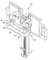
- the machine 1further comprises a feeding device 75 for feeding a diluent into a bottle 7 containing a lyophilized or powder pharmaceutical.
- the device 75comprises feeding assemblies 76 , two in the case in point, each of which comprises, in turn, a feeding reservoir 77 (e.g. a bag 9 ) for the diluent; a feeding needle 78 coupled to the frame 2 and hydraulically connected to the reservoir 77 by means of a pipe 79 ; and a pumping device defined, in the case in point, by a syringe 80 , which is connected to an intermediate point of the pipe 79 , and is actuated in known manner to aspirate a predetermined amount of diluent from the reservoir 77 and to feed the diluent itself into the bottle 7 .
- a feeding reservoir 77e.g. a bag 9
- a feeding needle 78coupled to the frame 2 and hydraulically connected to the reservoir 77 by means of a pipe 79
- a pumping devicedefined, in the case in point, by a syringe 80 , which is connected to an intermediate point of the pipe 79 , and is actu
- connection between the pipe 79 and the syringe 80divides the pipe 79 into two segments 79 a , 79 b , which are arranged in sequence and in this order between the reservoir 77 and the needle 78 , and which are provided with respective check valves 81 a , 81 b , of which valve 81 a avoids the flow back of diluent into segment 79 a when diluent is fed to the needle 78 , and valve 81 b avoids the flow back of diluent from segment 79 b when the diluent is aspirated from the reservoir 77 .
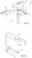
- the device 75further comprises a collection reservoir 82 , which extends underneath the needles 78 , is coupled in known manner to the frame 2 to move with respect to the frame 2 , in direction A between a lowered resting position ( FIG. 13 b ) and an operating raised position ( FIG. 13 a ), and is hydraulically connected to a collection manifold 83 of the diluent.
- the reservoir 82further displays a pair of tubes 84 , each of which protrudes upwards from a bottom wall of the reservoir 82 , is substantially coaxial to the respective needle 78 , and accommodates therein a protective cap 85 of the needle 78 itself arranged in the tube 84 with the concavity facing upwards.
- the reservoir 82is moved, with the caps 85 of the needles 78 , to its lowered resting position to allow inserting two bottles 7 underneath the needles 78 and feeding the diluent into the bottles 7 themselves.
- the bottlesWhen they are extracted from the respective bottles 7 the bottles may have residues of the lyophilized or powder pharmaceutical, and for this reason at the end of each injection operating cycle of the feeding device 75 , the reservoir 82 is moved into its raised operating position so as to fit the caps 85 on the respective needles 78 , and the syringes 80 are actuated to allow to wash the needles 78 with the diluent contained in the reservoirs 77 .
- the amount of diluent used to wash the needles 78also allows to wash the caps 85 ;
- the caps 85are, like the needles 78 , initially sterile and may therefore be used to wash the respective needles 78 at the end of each programmed injection operating cycles in a working session of the machine 1 ;
- the conclusion of the working session of the machine 1requires only the replacement of needles 78 and of the respective caps 85 and does not require the sterilization of the reservoir 82 .
- the machine 1is further provided with a collection device 86 of the processing waste (e.g. syringes 5 , bottle 7 , needles 78 , and caps 85 ) accommodated within the frame 2 underneath the store 8 , and comprising, in the case in point, two collection containers 87 , of which one (hereinafter indicated by numeral 87 a ) communicates with the chamber 3 by means of a pair of slides 88 and the other (hereinafter indicated by numeral 87 b ) communicates with the chamber 3 itself by means of one chute only 89 .
- a collection container 86 of the processing wastee.g. syringes 5 , bottle 7 , needles 78 , and caps 85
- two collection containers 87of which one (hereinafter indicated by numeral 87 a ) communicates with the chamber 3 by means of a pair of slides 88 and the other (hereinafter indicated by numeral 87 b ) communicates with the chamber 3 itself by means of one chute only 89
- the various processing wasteis selectively fed by the device 10 to the various chutes 88 , 89 and, thus, to the various containers 87 a , 87 b , thus allowing to separate the processing waste.
Landscapes
- Engineering & Computer Science (AREA)
- Mechanical Engineering (AREA)
- Medical Preparation Storing Or Oral Administration Devices (AREA)
Abstract
Description
Claims (6)
Priority Applications (3)
| Application Number | Priority Date | Filing Date | Title |
|---|---|---|---|
| US12/870,884US8539989B2 (en) | 2010-08-30 | 2010-08-30 | Method for the production of pharmaceutical products |
| CA2721628ACA2721628C (en) | 2010-08-30 | 2010-11-18 | Method for the production of pharmaceutical products |
| AU2010246352AAU2010246352B2 (en) | 2010-08-30 | 2010-11-19 | Method for the production of pharmaceutical products |
Applications Claiming Priority (1)
| Application Number | Priority Date | Filing Date | Title |
|---|---|---|---|
| US12/870,884US8539989B2 (en) | 2010-08-30 | 2010-08-30 | Method for the production of pharmaceutical products |
Publications (2)
| Publication Number | Publication Date |
|---|---|
| US20120048419A1 US20120048419A1 (en) | 2012-03-01 |
| US8539989B2true US8539989B2 (en) | 2013-09-24 |
Family
ID=45695546
Family Applications (1)
| Application Number | Title | Priority Date | Filing Date |
|---|---|---|---|
| US12/870,884Active2032-02-06US8539989B2 (en) | 2010-08-30 | 2010-08-30 | Method for the production of pharmaceutical products |
Country Status (3)
| Country | Link |
|---|---|
| US (1) | US8539989B2 (en) |
| AU (1) | AU2010246352B2 (en) |
| CA (1) | CA2721628C (en) |
Cited By (7)
| Publication number | Priority date | Publication date | Assignee | Title |
|---|---|---|---|---|
| US20120168573A1 (en)* | 2009-10-23 | 2012-07-05 | Truking Technology Limited | Positioning Device for Production Line of Large and Soft Infusion Bag |
| US20120199239A1 (en)* | 2009-10-14 | 2012-08-09 | Panasonic Corporation | System for assisting medicinal liquid preparation and method for assisting medicinal liquid preparation |
| US20120330152A1 (en)* | 2009-11-27 | 2012-12-27 | Claus-Peter Reisinger | Fluid management system |
| US20130308879A1 (en)* | 2012-05-18 | 2013-11-21 | Health Robotics S.R.L. | Gripping member of a bag for pharmaceutical products |
| US20140174600A1 (en)* | 2011-08-08 | 2014-06-26 | Yuyama Mfg. Co., Ltd. | Coinfusion apparatus |
| US11013857B2 (en) | 2016-07-06 | 2021-05-25 | Bayer Healthcare Llc | Contrast heating system with in-line contrast warmer |
| US20230285239A1 (en)* | 2022-03-08 | 2023-09-14 | Equashield Medical Ltd | Fluid transfer station in a robotic pharmaceutical preparation system |
Families Citing this family (7)
| Publication number | Priority date | Publication date | Assignee | Title |
|---|---|---|---|---|
| US20120048424A1 (en)* | 2010-08-30 | 2012-03-01 | Health Robotics S.R.L. | Method and Machine for the Preparation of Pharmaceutical Products |
| JP6318088B2 (en) | 2011-07-26 | 2018-04-25 | アンフォラ メディカル, インコーポレイテッド | Apparatus and method for modulating pelvic nerve tissue |
| WO2015120079A1 (en) | 2014-02-04 | 2015-08-13 | Amphora Medical, Inc. | Devices and methods for treating conditions caused by affarent nerve signals |
| JP2017516620A (en) | 2014-05-23 | 2017-06-22 | アンフォラ メディカル, インコーポレイテッド | Methods and devices for treatment of pelvic conditions |
| ITUA20161408A1 (en) | 2016-03-07 | 2017-09-07 | Swisslog Italia Spa | Machine and procedure for the preparation of intravenous medicaments |
| US12102596B2 (en)* | 2020-08-28 | 2024-10-01 | Omnicell, Inc. | Bag transfer mechanism for IV compounding |
| CN113650884B (en)* | 2021-07-27 | 2023-08-29 | 上海观道生物科技有限公司 | Packaging method of traditional Chinese medicine decoction |
Citations (16)
| Publication number | Priority date | Publication date | Assignee | Title |
|---|---|---|---|---|
| US4817443A (en)* | 1986-11-14 | 1989-04-04 | A.B.X. | Device for cleaning a liquid sample taking needle |
| US5525515A (en)* | 1993-02-03 | 1996-06-11 | Blattner; Frederick R. | Process of handling liquids in an automated liquid handling apparatus |
| US6360794B1 (en)* | 2000-12-19 | 2002-03-26 | Bechtel Bwxt Idaho, Llc | Apparatus and method for delivering a fluid to a container |
| US6616771B2 (en)* | 2001-11-30 | 2003-09-09 | Forhealth Technologies, Inc. | Method and system for cleaning and reusing a cannula |
| US20040154690A1 (en)* | 2002-12-03 | 2004-08-12 | Osborne Joel A. | Automated apparatus and process for reconstitution and delivery of medication to an automated syringe preparation apparatus |
| US6991002B2 (en)* | 2002-12-03 | 2006-01-31 | Forhealth Technologies, Inc. | Tamper evident syringe tip cap and automated method for preparing tamper-evident syringes |
| US7117902B2 (en)* | 2002-12-03 | 2006-10-10 | Forhealth Technologies, Inc. | Automated means of storing, dispensing and orienting injectable drug vials for a robotic application |
| US20060259195A1 (en)* | 2004-12-22 | 2006-11-16 | Eliuk Walter W | Automated pharmacy admixture system (APAS) |
| US7610115B2 (en)* | 2004-12-22 | 2009-10-27 | Intelligent Hospital Systems Ltd. | Automated pharmacy admixture system (APAS) |
| US7814731B2 (en)* | 2006-10-20 | 2010-10-19 | Forhealth Technologies, Inc. | Automated drug preparation apparatus including a bluetooth communications network |
| US7900658B2 (en)* | 2006-10-20 | 2011-03-08 | Fht, Inc. | Automated drug preparation apparatus including drug vial handling, venting, cannula positioning functionality |
| US7931859B2 (en)* | 2005-12-22 | 2011-04-26 | Intelligent Hospital Systems Ltd. | Ultraviolet sanitization in pharmacy environments |
| US8037659B2 (en)* | 2006-10-20 | 2011-10-18 | Forhealth Technologies, Inc. | Automated drug preparation apparatus including syringe loading, preparation and filling |
| US8151835B2 (en)* | 2006-08-23 | 2012-04-10 | Fht, Inc. | Automated drug delivery bag filling system |
| US8225824B2 (en)* | 2007-11-16 | 2012-07-24 | Intelligent Hospital Systems, Ltd. | Method and apparatus for automated fluid transfer operations |
| US8386070B2 (en)* | 2009-03-18 | 2013-02-26 | Intelligent Hospital Systems, Ltd | Automated pharmacy admixture system |
- 2010
- 2010-08-30USUS12/870,884patent/US8539989B2/enactiveActive
- 2010-11-18CACA2721628Apatent/CA2721628C/enactiveActive
- 2010-11-19AUAU2010246352Apatent/AU2010246352B2/enactiveActive
Patent Citations (22)
| Publication number | Priority date | Publication date | Assignee | Title |
|---|---|---|---|---|
| US4817443A (en)* | 1986-11-14 | 1989-04-04 | A.B.X. | Device for cleaning a liquid sample taking needle |
| US5525515A (en)* | 1993-02-03 | 1996-06-11 | Blattner; Frederick R. | Process of handling liquids in an automated liquid handling apparatus |
| US6360794B1 (en)* | 2000-12-19 | 2002-03-26 | Bechtel Bwxt Idaho, Llc | Apparatus and method for delivering a fluid to a container |
| US6616771B2 (en)* | 2001-11-30 | 2003-09-09 | Forhealth Technologies, Inc. | Method and system for cleaning and reusing a cannula |
| US7240699B2 (en)* | 2002-12-03 | 2007-07-10 | Forhealth Technologies, Inc | Automated means for storing, dispensing and orienting injectable drug vials for a robotic application |
| US20040154690A1 (en)* | 2002-12-03 | 2004-08-12 | Osborne Joel A. | Automated apparatus and process for reconstitution and delivery of medication to an automated syringe preparation apparatus |
| US6915823B2 (en)* | 2002-12-03 | 2005-07-12 | Forhealth Technologies, Inc. | Automated apparatus and process for reconstitution and delivery of medication to an automated syringe preparation apparatus |
| US6991002B2 (en)* | 2002-12-03 | 2006-01-31 | Forhealth Technologies, Inc. | Tamper evident syringe tip cap and automated method for preparing tamper-evident syringes |
| US7117902B2 (en)* | 2002-12-03 | 2006-10-10 | Forhealth Technologies, Inc. | Automated means of storing, dispensing and orienting injectable drug vials for a robotic application |
| US7610115B2 (en)* | 2004-12-22 | 2009-10-27 | Intelligent Hospital Systems Ltd. | Automated pharmacy admixture system (APAS) |
| US20060259195A1 (en)* | 2004-12-22 | 2006-11-16 | Eliuk Walter W | Automated pharmacy admixture system (APAS) |
| US7783383B2 (en)* | 2004-12-22 | 2010-08-24 | Intelligent Hospital Systems Ltd. | Automated pharmacy admixture system (APAS) |
| US20100198392A1 (en)* | 2005-05-16 | 2010-08-05 | Intelligent Hospital Systems Ltd. | Automated pharmacy admixture system (apas) |
| US7930066B2 (en)* | 2005-05-16 | 2011-04-19 | Intelligent Hospital Systems Ltd. | Automated pharmacy admixture system (APAS) |
| US7931859B2 (en)* | 2005-12-22 | 2011-04-26 | Intelligent Hospital Systems Ltd. | Ultraviolet sanitization in pharmacy environments |
| US8151835B2 (en)* | 2006-08-23 | 2012-04-10 | Fht, Inc. | Automated drug delivery bag filling system |
| US7814731B2 (en)* | 2006-10-20 | 2010-10-19 | Forhealth Technologies, Inc. | Automated drug preparation apparatus including a bluetooth communications network |
| US7900658B2 (en)* | 2006-10-20 | 2011-03-08 | Fht, Inc. | Automated drug preparation apparatus including drug vial handling, venting, cannula positioning functionality |
| US8037659B2 (en)* | 2006-10-20 | 2011-10-18 | Forhealth Technologies, Inc. | Automated drug preparation apparatus including syringe loading, preparation and filling |
| US8209941B2 (en)* | 2006-10-20 | 2012-07-03 | Fht, Inc. | Automated drug preparation apparatus including syringe loading, preparation and filling |
| US8225824B2 (en)* | 2007-11-16 | 2012-07-24 | Intelligent Hospital Systems, Ltd. | Method and apparatus for automated fluid transfer operations |
| US8386070B2 (en)* | 2009-03-18 | 2013-02-26 | Intelligent Hospital Systems, Ltd | Automated pharmacy admixture system |
Cited By (22)
| Publication number | Priority date | Publication date | Assignee | Title |
|---|---|---|---|---|
| US20120199239A1 (en)* | 2009-10-14 | 2012-08-09 | Panasonic Corporation | System for assisting medicinal liquid preparation and method for assisting medicinal liquid preparation |
| US20120168573A1 (en)* | 2009-10-23 | 2012-07-05 | Truking Technology Limited | Positioning Device for Production Line of Large and Soft Infusion Bag |
| US8746297B2 (en)* | 2009-10-23 | 2014-06-10 | Truking Technology Limited | Positioning device for production line of large and soft infusion bag |
| US9555189B2 (en)* | 2009-11-27 | 2017-01-31 | Bayer Intellectual Property Gmbh | Fluid management device having rotating carousel with container holders for vertically positioning a container during automated spiking and injection into patient |
| US20120330152A1 (en)* | 2009-11-27 | 2012-12-27 | Claus-Peter Reisinger | Fluid management system |
| US9561156B2 (en)* | 2011-08-08 | 2017-02-07 | Yuyama Mfg. Co., Ltd. | Coinfusion apparatus |
| US8857476B2 (en)* | 2011-08-08 | 2014-10-14 | Yuyama Mfg. Co., Ltd. | Coinfusion apparatus |
| US20140373975A1 (en)* | 2011-08-08 | 2014-12-25 | Yuyama Mfg. Co., Ltd. | Coinfusion apparatus |
| US20140174600A1 (en)* | 2011-08-08 | 2014-06-26 | Yuyama Mfg. Co., Ltd. | Coinfusion apparatus |
| US9399002B2 (en)* | 2012-05-18 | 2016-07-26 | Health Robotics S.R.L. | Gripping member of a bag for pharmaceutical products |
| US20130308879A1 (en)* | 2012-05-18 | 2013-11-21 | Health Robotics S.R.L. | Gripping member of a bag for pharmaceutical products |
| US11013857B2 (en) | 2016-07-06 | 2021-05-25 | Bayer Healthcare Llc | Contrast heating system with in-line contrast warmer |
| US11865074B2 (en)* | 2022-03-08 | 2024-01-09 | Equashield Medical Ltd | Fluid transfer station in a robotic pharmaceutical preparation system |
| US11857497B2 (en) | 2022-03-08 | 2024-01-02 | Equashield Medical Ltd | Fluid transfer station in a robotic pharmaceutical preparation system |
| US20230285239A1 (en)* | 2022-03-08 | 2023-09-14 | Equashield Medical Ltd | Fluid transfer station in a robotic pharmaceutical preparation system |
| US11865075B2 (en) | 2022-03-08 | 2024-01-09 | Equashield Medical Ltd | Fluid transfer station in a robotic pharmaceutical preparation system |
| US11925600B2 (en) | 2022-03-08 | 2024-03-12 | Equashield Medical Ltd | Fluid transfer station in a robotic pharmaceutical preparation system |
| US11931313B2 (en) | 2022-03-08 | 2024-03-19 | Equashield Medical Ltd | Fluid transfer station in a robotic pharmaceutical preparation system |
| US11938091B2 (en) | 2022-03-08 | 2024-03-26 | Equashield Medical Ltd | Fluid transfer station in a robotic pharmaceutical preparation system |
| US11992462B2 (en) | 2022-03-08 | 2024-05-28 | Equashield Medical Ltd | Fluid transfer station in a robotic pharmaceutical preparation system |
| US12370125B2 (en) | 2022-03-08 | 2025-07-29 | Equashield Medical Ltd | Fluid transfer station in a robotic pharmaceutical preparation system |
| US12414899B2 (en) | 2022-03-08 | 2025-09-16 | Equashield Medical Ltd | Fluid transfer station in a robotic pharmaceutical preparation system |
Also Published As
| Publication number | Publication date |
|---|---|
| AU2010246352A1 (en) | 2012-03-15 |
| CA2721628C (en) | 2018-01-30 |
| AU2010246352B2 (en) | 2016-02-25 |
| CA2721628A1 (en) | 2012-02-29 |
| US20120048419A1 (en) | 2012-03-01 |
Similar Documents
| Publication | Publication Date | Title |
|---|---|---|
| US8539989B2 (en) | Method for the production of pharmaceutical products | |
| US8499919B2 (en) | Machine for the production of pharmaceutical products | |
| US8632738B2 (en) | Syringe actuating method and assembly | |
| US8865070B2 (en) | Machine for the production of pharmaceutical products | |
| EP2054145B1 (en) | Device for the preparation of pharmaceutical products | |
| US20120048424A1 (en) | Method and Machine for the Preparation of Pharmaceutical Products | |
| US8794276B2 (en) | Method and machine for the preparation of pharmaceutical products | |
| EP2502610B1 (en) | Method for the preparation of pharmaceutical products | |
| CN101511461A (en) | Machine for the preparation of pharmaceutical products | |
| EP2511183B1 (en) | Syringe actuating method and assembly | |
| EP2502670B1 (en) | Machine for the preparation of pharmaceutical products | |
| EP2502669B1 (en) | Machine for the preparation of pharmaceutical products |
Legal Events
| Date | Code | Title | Description |
|---|---|---|---|
| AS | Assignment | Owner name:HEALTH ROBOTICS S.R.L., ITALY Free format text:ASSIGNMENT OF ASSIGNORS INTEREST;ASSIGNORS:GIRIBONA, PAOLO;BIANCO, WALTER;MINISINI, MICHELE;AND OTHERS;SIGNING DATES FROM 20101102 TO 20101103;REEL/FRAME:025360/0431 | |
| STCF | Information on status: patent grant | Free format text:PATENTED CASE | |
| AS | Assignment | Owner name:TPG SPECIALTY LENDING, INC., AS ADMINISTRATIVE AGE Free format text:PATENT SECURITY AGREEMENT;ASSIGNOR:AESYNT TOPCO B.V.;REEL/FRAME:032981/0671 Effective date:20140508 | |
| AS | Assignment | Owner name:AESYNT TOPCO B.V., NETHERLANDS Free format text:ASSIGNMENT OF ASSIGNORS INTEREST;ASSIGNOR:HEALTH ROBOTICS S.R.L.;REEL/FRAME:032986/0613 Effective date:20140508 | |
| AS | Assignment | Owner name:AESYNT B.V. (FORMERLY KNOWN AS AESYNT TOPCO B.V.), Free format text:RELEASE BY SECURED PARTY;ASSIGNOR:TPG SPECIALTY LENDING, INC., AS ADMINISTRATIVE AGENT;REEL/FRAME:037410/0622 Effective date:20160105 | |
| FEPP | Fee payment procedure | Free format text:PAT HOLDER NO LONGER CLAIMS SMALL ENTITY STATUS, ENTITY STATUS SET TO UNDISCOUNTED (ORIGINAL EVENT CODE: STOL); ENTITY STATUS OF PATENT OWNER: LARGE ENTITY | |
| FPAY | Fee payment | Year of fee payment:4 | |
| AS | Assignment | Owner name:OMNICELL, INC., CALIFORNIA Free format text:ASSIGNMENT OF ASSIGNORS INTEREST;ASSIGNOR:AESYNT B.V.;REEL/FRAME:050938/0824 Effective date:20190101 Owner name:AESYNT B.V., NETHERLANDS Free format text:CHANGE OF NAME;ASSIGNOR:AESYNT TOPCO B.V.;REEL/FRAME:050938/0788 Effective date:20150701 | |
| MAFP | Maintenance fee payment | Free format text:PAYMENT OF MAINTENANCE FEE, 8TH YEAR, LARGE ENTITY (ORIGINAL EVENT CODE: M1552); ENTITY STATUS OF PATENT OWNER: LARGE ENTITY Year of fee payment:8 | |
| AS | Assignment | Owner name:WELLS FARGO BANK, NATIONAL ASSOCIATION, AS ADMINISTRATIVE AGENT, VIRGINIA Free format text:SECURITY INTEREST;ASSIGNOR:OMNICELL, INC.;REEL/FRAME:066703/0184 Effective date:20240223 | |
| MAFP | Maintenance fee payment | Free format text:PAYMENT OF MAINTENANCE FEE, 12TH YEAR, LARGE ENTITY (ORIGINAL EVENT CODE: M1553); ENTITY STATUS OF PATENT OWNER: LARGE ENTITY Year of fee payment:12 |