US8539177B1 - Partitioning of a storage array into N-storage arrays using virtual array non-disruptive data migration - Google Patents
Partitioning of a storage array into N-storage arrays using virtual array non-disruptive data migrationDownload PDFInfo
- Publication number
- US8539177B1 US8539177B1US11/427,731US42773106AUS8539177B1US 8539177 B1US8539177 B1US 8539177B1US 42773106 AUS42773106 AUS 42773106AUS 8539177 B1US8539177 B1US 8539177B1
- Authority
- US
- United States
- Prior art keywords
- array
- destination
- virtual
- source
- storage
- Prior art date
- Legal status (The legal status is an assumption and is not a legal conclusion. Google has not performed a legal analysis and makes no representation as to the accuracy of the status listed.)
- Active, expires
Links
Images


Classifications
- G—PHYSICS
- G06—COMPUTING OR CALCULATING; COUNTING
- G06F—ELECTRIC DIGITAL DATA PROCESSING
- G06F3/00—Input arrangements for transferring data to be processed into a form capable of being handled by the computer; Output arrangements for transferring data from processing unit to output unit, e.g. interface arrangements
- G06F3/06—Digital input from, or digital output to, record carriers, e.g. RAID, emulated record carriers or networked record carriers
- G06F3/0601—Interfaces specially adapted for storage systems
- G06F3/0628—Interfaces specially adapted for storage systems making use of a particular technique
- G06F3/0646—Horizontal data movement in storage systems, i.e. moving data in between storage devices or systems
- G06F3/0647—Migration mechanisms
- G—PHYSICS
- G06—COMPUTING OR CALCULATING; COUNTING
- G06F—ELECTRIC DIGITAL DATA PROCESSING
- G06F3/00—Input arrangements for transferring data to be processed into a form capable of being handled by the computer; Output arrangements for transferring data from processing unit to output unit, e.g. interface arrangements
- G06F3/06—Digital input from, or digital output to, record carriers, e.g. RAID, emulated record carriers or networked record carriers
- G06F3/0601—Interfaces specially adapted for storage systems
- G06F3/0602—Interfaces specially adapted for storage systems specifically adapted to achieve a particular effect
- G06F3/0614—Improving the reliability of storage systems
- G06F3/0617—Improving the reliability of storage systems in relation to availability
- G—PHYSICS
- G06—COMPUTING OR CALCULATING; COUNTING
- G06F—ELECTRIC DIGITAL DATA PROCESSING
- G06F3/00—Input arrangements for transferring data to be processed into a form capable of being handled by the computer; Output arrangements for transferring data from processing unit to output unit, e.g. interface arrangements
- G06F3/06—Digital input from, or digital output to, record carriers, e.g. RAID, emulated record carriers or networked record carriers
- G06F3/0601—Interfaces specially adapted for storage systems
- G06F3/0668—Interfaces specially adapted for storage systems adopting a particular infrastructure
- G06F3/0671—In-line storage system
- G06F3/0683—Plurality of storage devices
- G06F3/0689—Disk arrays, e.g. RAID, JBOD
Definitions
- the present inventionrelates generally to storage systems. More particularly, the invention relates to partitioning a storage array into multiple storage arrays using virtual array migration.
- a prior art “storage group”includes at least one host and a set of logical units of storage. The logical units of storage in the group are accessible only to the hosts in the storage group. Other hosts cannot access a storage group to which they have not been granted access.
- Current methods for partitioning storage arrays into virtual arrayscan be highly complex and expensive, and operate only at the storage array level. It is desirable to provide a simpler, inexpensive means of presenting virtual arrays to host systems, and to provide a mechanism for centralizing virtual array partitioning from another part of the system, for example, the switch fabric. It is also desirable to be able to migrate data between virtual arrays.
- the inventionfeatures a method of migrating data stored logical units of storage (LUNs) at a source storage array to a plurality of destination storage arrays transparently with respect to a host in communication with the source storage array through a switch.
- the source storage arrayis divided into a plurality of source virtual arrays including a first source virtual array and a second source virtual array and each destination storage array is divided into one or more destination virtual arrays.
- data stored in a LUN of the first source virtual arrayare copied to a corresponding LUN of a destination virtual array of a first one of the destination storage arrays.
- Data stored in a LUN of the second source virtual arrayare copied to a corresponding LUN of a destination virtual array of a second one of the destination storage arrays.
- the inventionfeatures a storage network comprising a switch, first and second destination storage arrays coupled to the switch, and a source storage array coupled to the switch.
- Each destination storage arrayis partitioned into one or more destination virtual arrays
- the source storage arrayis partitioned into a plurality of source virtual arrays including a first source virtual array and a second source virtual array.
- Each source virtual arraycomprises a distinct group of logical units of storage (LUNs).
- a replication engine of the source storage arraycopies a LUN of the first source virtual array to a corresponding LUN of a first destination virtual array of the first destination storage array and a LUN of the second source virtual array to a corresponding LUN of a second destination virtual array of the second destination storage array.
- the inventionfeatures a method of migrating data stored in logical units of storage (LUNs) at a source storage array to a plurality of destination storage arrays transparently with respect to a host in communication with the source storage array through a switch.
- the source storage arrayis divided into a plurality of source virtual arrays including a first source virtual array and a second source virtual array, and each destination storage array is divided into one or more destination virtual arrays.
- data stored in a LUN of the first source virtual arrayare copied to a corresponding LUN of a destination virtual array of a first one of the destination storage arrays
- data stored in a LUN of the second source virtual arrayare copied to a corresponding LUN of a destination virtual array of a second one of the destination storage arrays.
- connection information, management information and metadata associated with the first source virtual arrayare transferred to the first destination storage array where said connection information, management information, and metadata become associated with the destination virtual array of the first destination storage array.
- Connection information, management information, and metadata associated with the second source virtual arrayare transferred to the second destination storage array where said connection, information, management information and metadata become associated with the destination virtual array of the second destination storage array.
- FIG. 1is a functional block diagram of an embodiment of a storage area network (SAN) in communication with a plurality of hosts including a management station, the SAN including multiple storage arrays coupled to the hosts through a switch fabric and to the management station through a network.
- SANstorage area network
- FIG. 2is a representation of an embodiment of a SAN, wherein the logical units (LUNs) of storage in a storage array are arranged into storage groups (i.e., virtual arrays) and are separately addressable through virtual port identifiers (IDs).
- LUNslogical units
- IDsvirtual port identifiers
- FIG. 3is a flow diagram of an embodiment of a process by which the switch assigns port IDs to array ports of the storage array.
- FIG. 4is an exemplary representation of a name server table resident in the switch fabric.
- FIG. 5is an exemplary representation of a LUN table used by hosts to map LUN numbers to port IDs and LUN names
- FIG. 6is a flow diagram of an embodiment of a process for assigning virtual port IDs to array ports of the storage array.
- FIG. 7is an exemplary representation of a name server table resident in the switch fabric used to map port names and IDs to virtual port names and virtual port IDs.
- FIG. 8is an exemplary representation of a LUN table used by hosts to map LUN names to virtual port IDs and LUN numbers
- FIG. 9are exemplary representations of an array name table used by a host to map serial numbers to array names and of a DNS table used to resolve array names to IP addresses.
- FIG. 10is a functional block diagram representation of an embodiment of a storage array.
- FIG. 11is a functional block diagram representation of virtual array migration.
- FIG. 12is a flow diagram of an embodiment of process for performing virtual array migration as illustrated in FIG. 11 .
- FIG. 13is a first exemplary representation of the array name and DNS tables of FIG. 9 after completion of the data migration event.
- FIG. 14is a second exemplary representation of the array name and DNS tables of FIG. 9 after completion of the data migration event.
- FIG. 15is a block diagram representation of a data migration event in which a single source storage array is partitioned into multiple destination storage arrays using virtual array migration.
- FIG. 16is a flow diagram of an embodiment of process for partitioning data at a single source storage array into multiple destination storage arrays using virtual array migration.
- FIG. 17are exemplary representations of an array name table used by a host to map serial numbers to storage array names and of a DNS table used to resolve storage array names to IP addresses before the array partitioning of FIG. 15 and FIG. 16 .
- FIG. 18is a first exemplary representation of the array name and DNS tables of FIG. 17 after completion of the array partitioning.
- FIG. 19is a second exemplary representation of the array name and DNS tables of FIG. 17 after completion of the array partitioning.
- FIG. 20is a block diagram representation of a data migration event in which data at multiple source arrays are consolidated into a single destination array using virtual array migration.
- FIG. 21is a flow diagram of an embodiment of process for consolidating data resident at multiple source storage arrays into a single destination storage array using virtual array migration.
- FIG. 22are exemplary representations of an array name table used by a host to map serial numbers to storage array names and of a DNS table used to resolve storage array names to IP addresses before the array consolidation of FIG. 20 and FIG. 21 .
- FIG. 23is a first exemplary representation of the array name and DNS tables of FIG. 22 after completion of the array consolidation.
- FIG. 24is a second exemplary representation of the array name and DNS tables of FIG. 22 after completion of the array consolidation.
- Storage networks embodying the inventioninclude storage arrays that are partitioned into virtual arrays.
- dataare migrated from one or more source virtual arrays to one or more destination virtual arrays.
- the migration of the dataoccurs transparently with respect to the hosts and host applications that may be communicating with the virtual arrays.
- the source and destination virtual arraysexchange connection information (i.e., the names of their virtual array ports and of their logical units or LUNs).
- the exchange of the connection informationcauses the hosts to communicate with the destination virtual array instead of with the source virtual array. This enables host communication with the migrated LUNs to continue uninterrupted, thereby eliminating application downtime for an array upgrade or replacement.
- each virtual arraypresents its own virtual array management interface (i.e., for control plane functionality) to hosts.
- Management applications running on the hostsuse the management interfaces to communicate directly and independently with each virtual array for managing that virtual array and its associated LUNs. Examples of information provided by the management interfaces include IP addresses, logical serial numbers, virtual array names, and gatekeepers.
- the source and destination virtual arraysalso exchange virtual array management interfaces during a data migration event.
- the exchange of management interfacesmakes the migration of data and connection information transparent to management applications executing on the hosts. That is, management applications can continue to communicate with the virtual arrays, unaffected or uninterrupted by the data and connection migration, in effect, unaware of the transfer of data from one virtual array to another virtual array. Consequently, data migration events require no modification to many of the commercially available management applications used by administrators to manage their storage networks.
- metadataare associated with applications that extend storage functionality, examples of which are data back-up applications.
- the metadatarepresents information critical to the proper operation of the extended storage functionality application. If a data migration event occurs during execution of an extended storage functionality application, then migration of the metadata to the destination virtual array ensures that the extended storage functionality application can continue to operate properly after the data migration event.
- Storage networks constructed in accordance with other embodiments of the inventionuse virtual array migration to migrate data from a single source storage array to a plurality of destination storage arrays in a process referred to as array partitioning.
- Other embodiments of storage networksuse virtual array migration to migrate data from a plurality of source storage arrays to a single destination storage array in a process referred to as array consolidation.
- each source and destination storage arrayis organized into virtual arrays.
- the data, connections, and management interfaces of the source virtual arraysare migrated to the virtual arrays of multiple destination storage arrays.
- the data, connections, and management interface of at least one source virtual array from each one of multiple source storage arraysare migrated to the virtual arrays of a single destination storage array.
- the array partitioning and array consolidation processescan also include the transfer of extended storage functionality metadata between source and destination virtual arrays.
- FIG. 1shows an exemplary storage area network (SAN) 10 in which the invention can be implemented.
- the SAN 10employs a Fibre Channel fabric topology.
- Fibre Channelis a high-speed serial transport used in storage systems. The transport is described in a series of standards that can be found at X 3 T 9.3 Task Group of ANSI: Fibre Channel Physical and Signaling Interface ( FC - PH ), Rev. 4.2 Oct. 8, 1993.
- Hosts 12shown individually as host 12 a , host 12 b , and host 12 c , are coupled to a Fibre Channel “fabric” in the storage system, herein shown as a switch 14 .
- Storage arrays 16are also coupled to the switch 14 .
- the hosts 12communicate with disks or disk drives 58 ( FIG. 2 ) of any of the storage arrays 16 using a cross-point Fibre Channel connection through the switch 14 .
- Each storage array 16is partitioned into one or more virtual arrays ( FIG. 2 ) and has a virtual array management interface—i.e., management information by which a remotely executing management application may identify a virtual array and its devices (e.g., logical units or LUNs) and send management messages or packets specifically to the virtual array.
- the virtual arrayscan export their array management interfaces through an application program interface (API). Through use of this management API, management applications can manage and control the virtual arrays and their devices (e.g., LUNs).
- the virtual array management interface of each virtual arrayincludes such management information as a logical serial number, an array name, a network address (e.g., IP address), a gatekeeper (for some types of storage arrays, e.g., EMC Corporation's SymmetrixTM), and alphanumeric identifiers for the LUNs of that storage array.
- a gatekeeperas used herein, is a small LUN that maintains data about the LUNs of the associated virtual array. Management applications can communicate with the gatekeeper, for example, to discover the LUNs on the virtual array.
- Another host 18is also in communication with the storage arrays 16 over a network 20 .
- Executing at the management station 18is a management application 22 used by a storage network administrator to manage (i.e., discover, access, configure, and monitor) the virtual arrays and their LUNs.
- management applicationsthat may be used in the practice of the invention include, but are not limited to, NAVISPHERE® Management Suite and EMC Control Center (ECC)®/Open Edition, each produced by EMC Corporation of Hopkinton, Mass.
- Communication between the management host 18 and the storage arrays 16can transpire in accordance with any transport protocol.
- the host 18 and storage arrays 16can communicate over the IP network 20 according to the TCP/IP and HTTP protocols.
- the host 18 and storage arrays 16can communicate through the Fibre Channel switch 14 using the Fibre Channel protocol.
- an array name table 24maintains associations of array serial numbers with array names.
- a Domain Name Server (DNS) 26maintains associations of storage array names with network IP addresses.
- the array names in the array name table 24 and at the DNS 26correspond to virtual array names (i.e., those array names given to virtual arrays of the storage arrays 16 ).
- the management station 18maintains the array name table 24
- the DNS server 26resides on the network 20 .
- the host 12 chas a host application 28 referred to generally as an extended storage functionality application.
- the host application 28includes program code for providing particular storage functionality on the data stored in the disks 58 at a storage array.
- the storage arrayshave program code 30 that cooperates with the host application 28 to achieve the storage functionality.
- This program code 30 at the storage arraymaintains, updates, and uses metadata throughout its execution to accomplish the designed functionality of the host application 28 .
- a data back-up programcopies the data contents of a production device to a backup device located in the same storage array.
- the copyis a snapshot in time of the data of the production device.
- the backup programmaintains certain types of metadata, e.g., information that tracks which logical blocks of a device have been copied to the backup device, and changes (i.e., deltas) to the contents of the production device that have occurred since the backup program started executing.
- An example of data back-up programthat may be adapted to practice the invention is SnapViewTM, produced by EMC Corporation of Hopkinton, Mass.
- the principles of the inventionapply to various types of extended storage functionality applications, provided such applications produce and maintain metadata. Different extended storage functionality applications typically employ different types of metadata, and any type of metadata may be migrated from one virtual array to another virtual array, as described herein.
- FIG. 2shows the hosts 12 a , 12 b , the storage array 16 a , and the switch 14 in more detail.
- Storage array 16 ais a representative example of the storage arrays 16 , although each of the storage arrays can have fewer or more ports and LUNs than those shown for storage array 16 a .
- the switch 14includes switch ports 50 .
- switch ports 50 that are coupled to a hostare referred to as host-facing ports, and those that are coupled to a storage array are referred to as array-facing ports.
- host-facing switch portsare labeled as 50 h
- array-facing switch portsare labeled as 50 a .
- Host ports 52 on the hosts 12are coupled by Fibre Channel links 54 to host-facing switch ports 50 h on the switch 14 .
- Physical array ports 56 on the array 16 aare coupled by Fibre Channel links 54 to array-facing switch ports 50 a on the switch 14 .
- the storage array 16 aincludes an array of disks 58 and a controller 65 .
- the disks 58are organized into logical units (LUNs) 60 , originally a SCSI (small computer system interface) term, now commonly used to describe a logical unit of physical storage space.
- LUNslogical units
- the storage array 16 aexports the LUNs 60 over the Fibre Channel links 54 through the switch 14 , for access by the hosts 12 .
- each disk 58is configured as a separate LUN 60 , though it is understood that a LUN can encompass part of a disk, or parts of multiple disks, or multiple complete disks. The arrangement shown is chosen for convenience of description.
- each Fibre Channel device(including, but not limited to, host ports, array ports, and LUNs) has two identifying characteristics—a name and an address.
- Fibre Channel namesknown as “world wide names”, are unique—every Fibre Channel device in the world has its own unique name.
- Each Fibre Channel device in a systemalso has an address, referred to in Fibre Channel parlance as an “ID”.
- the Fibre Channel addressis dynamic and dependent upon the configuration of the system.
- the IDsare used for directing information between the hosts 12 and the storage arrays 16 and LUNs 60 in the system. Port addresses are referred to as “port IDs”.
- the hosts 12communicate with the storage arrays 16 and LUNs 60 by sending messages to the appropriate array port and LUN addresses.
- the hosts 12adapt to new port and LUN addresses, but each device in use maintains its same name in order for uninterrupted communications to continue.
- the switch 14assigns IDs to the host ports 52 and array ports 56 during initialization.
- IDsas described in the Fibre Channel specification, are 24-bit quantities containing several fields.
- the ID assigned to an array port 56is a derivative of the switch name and the ID of the switch port 50 .
- the name of an array port 56depends on the switch port 50 to which the array port 56 is coupled.
- names and IDsare shown symbolically with alphanumeric symbols for simplicity of explanation.
- the host ports 52 for hosts 12 a , 12 bare shown to have name-ID pairs of (ha, 100 ) and (hb, 102 ), respectively.
- the name-ID pairs of the host-facing switch ports 50 hare shown as (hfa, 200 ), (hfb, 201 ), (hfc, 202 ), and (hfd, 203 ).
- the host-facing port (hfa, 200 )is coupled to the host port (ha, 100 ) on the host 12 a and the host-facing port (hpb, 201 ) is coupled to the host port (hb, 102 ), on the host 12 b.
- Each array-facing switch port 50 and each array port 56have a name and ID.
- the array ports 56 of the storage array 16 ahave name-ID pairs of (apa, 0 ) and (apb, 1 ).
- the array-facing switch ports 50have the following name-ID pairs: array-facing switch port (afa, 300 ) is coupled to the array port 56 (apa, 0 ), and array-facing switch port (afb, 301 ) is coupled to an array port 56 (apb, 1 ).
- Each LUN 60 in the array 16 aalso has a name and a LUN number, referred to as a name/number pair (LUN name, LUN number).
- the array 16 aincludes a LUN with a name/number pair of (a 0 , L 00 )—the LUN has a name of “a 0 ” and a LUN number of L 00 .
- the LUNs with LUN numbers L 00 , L 01 , L 02 , L 10 , L 11 , L 12 , L 20 , L 21 , L 22 , L 30 , L 31 , L 32 , L 40 , L 41 , L 42 , L 50 , L 51 , and L 52are accessible through the array port (apa, 0 ), and LUNs with LUN numbers L 50 , L 51 , L 52 , L 60 , L 61 , L 62 , L 70 , L 71 , L 72 , L 80 , L 81 , L 82 , L 90 , L 91 , and L 92 are accessible through array port (apb, 1 ).
- the Fibre Channel switch 14includes a name server database 70 .
- the switch 14uses the name server database 70 to assign IDs to host ports 52 and to array ports 56 during initialization.
- the name server database 70includes a name server table 72 used by the switch 14 to resolve IDs to names.
- a name serverseparate and distinct from the switch 14 , maintains the name-server database 70 .
- FIG. 3shows an embodiment of a process by which Fibre Channel switch 14 assigns port IDs in accordance with the ANSI T11 Fibre Channel standards.
- a Fibre Channel device attached to a switch portfor example the array 16 a , sends the names of the array ports 56 to the switch 14 .
- the name server database 70sends, to the storage array 16 a , an ID for each array port 56 .
- the name server database 70stores each array port name and corresponding ID in an entry in the name server table 72 .
- the switch 14sends the name server table 72 to all members of the SAN 10 registered to receive state change notifications. This includes the hosts 12 (and the management station 18 ).
- the hosts 12have the IDs of the arrays 16 so that Fibre Channel communications between the hosts 12 and arrays 16 can ensue.
- the array controller 65sends (step 40 ) a port login “FLOGI” command for each array port (i.e., ports 0 and 1 ) to the switch 14 containing the array port name.
- the switchreceives the port login commands and responds (step 42 ) by sending an acknowledgement message to the array controller 65 .
- Each acknowledgement messagecontains a Port ID for the array port for which a login command has been sent.
- the array controller 65receives (step 43 ) the acknowledgement message.
- the eventis registered (step 44 ) with a name server.
- the name serverupdates (step 45 ) the name server table 72 containing port names and their corresponding port IDs and distributes the table 72 to the devices, including hosts 12 , 18 , that are registered to receive it.
- FIG. 4shows a portion of an exemplary embodiment of the name server table 72 .
- the name server table 72includes multiple entries 74 . Each entry 74 includes a port name field 76 and a port address field 78 .
- the full contents of the name server table 72are described in the Fibre Channel Name Server MIB, described in the IETF RFC 4044, “Fibre Channel Management MIB”, herein incorporated by reference.
- the name server table 72includes entries 74 for the port names apa and apb.
- the port ID 0 and port ID 1have been assigned by the Fibre Channel switch 14 to the port names apa and apb, respectively.
- the hosts 12After the hosts 12 have IDs to access the array ports 56 , they can learn what LUNs 60 are available. LUN names and numbers are managed at the array level. Each host 12 sends a query to each array port 56 ID, in turn, requesting a list of available LUN numbers. After the LUN numbers for a given array port ID are known, the host 12 is able to query each LUN 60 by using a combination of the port ID and LUN number to access the LUNs 60 . The host 12 then queries each LUN 60 for its corresponding LUN name. After the host 12 has gathered this information, it builds a directory LUN table 80 that relates LUN names, to port IDs and LUN numbers.
- FIG. 5shows a representative embodiment of a LUN table 80 .
- the LUN table 80includes an entry 82 for each LUN 60 that the host has discovered.
- Each entry 82includes a LUN name field 84 , a port ID field 88 , and a LUN number field 90 , which, in combination, identify the LUN 60 .
- the LUN table 80 for a host 12includes the LUN names, port IDs, and LUN numbers for the LUNs 60 on the array 16 a for each port ID 0 and 1 .
- one entry 82shows a LUN with name a 0 and LUN number L 00 associated with Port ID 0
- another entry 82shows a LUN with name e 1 and LUN number L 71 associated with Port ID 1 .
- hosts 12refer to LUNs 60 by their LUN numbers.
- a host port 52sends a message whose Fibre Channel address includes the array port ID and LUN number.
- the switch 14parses the port ID portion of the address in order to forward the message to the identified array port 56 .
- the array 16then uses the LUN number portion of the address to access the proper LUN 60 within the array 16 . For example, if host 12 a needs to access LUN #L 71 , the host port 52 sends a message to an address that includes the port ID 1 and the LUN number 71 .
- the switch 14sees the port ID 1 and sends the message to the array port 56 with ID 1 .
- the array 16 asees that the message is directed to the LUN #L 71 and proceeds to perform the appropriate operation on LUN number 71 .
- the LUNs 60are arranged in several separately accessible sub-arrays or storage groups 66 , also referred to herein as virtual arrays, individually labeled 66 a , 66 b , 66 c , 66 d , and 66 e .
- the term “storage group”can have different meanings in different contexts.
- a “storage group” in prior art, software-based virtual arraysinclude a host and a set of LUNs.
- a “storage group” as used hereinis a group of LUNs (i.e., without a host).
- a first storage group or virtual array 66 aincludes LUN numbers L 00 -L 12
- a second storage group or virtual array 66 bincludes LUN numbers L 20 -L 32
- Storage groupsappear as individual virtual arrays to the hosts 12 and may be referred to herein as “presented virtual arrays”.
- the number of virtual arrays in a storage array and the number of LUNs in a virtual arraycan vary from that shown with respect to storage array 16 a .
- a given LUNcan belong to one virtual array only.
- the Fibre Channel controller 65(shown), a separate controller, pre-configured software, dynamic user programming of the array 16 , or any combination thereof, can determine which LUNs are within each virtual array.
- Each virtual array 66may also include a gatekeeper 68 (i.e., a small LUN) for maintaining metadata about the LUNs within that virtual array (e.g., the name and number of each LUN).
- Each virtual array 66is also associated with at least one unique “virtual port ID”. These virtual port IDs are established over each physical port (apa, apb) on the array 16 a . In general, each presented virtual array 66 is assigned a number of virtual port IDs depending upon a number of physical ports through which that virtual array is accessible.
- the virtual array 66 ais associated with the physical array Port ID 0 and is assigned one virtual port ID v 0 .
- the virtual array 66 bis associated with the physical array Port ID 0 , and is assigned one virtual port ID v 1 .
- the virtual array 66 cis associated with the physical array port having Port ID 0 and with the array port having Port ID 1 .
- the virtual array 66 cis assigned two virtual port IDs v 2 and v 5 .
- the virtual arrays 66 d , 66 eare each associated with the physical array port ID 1 and are assigned virtual port IDs v 3 and v 4 , respectively. Accordingly, each virtual array 66 has assigned thereto at least one virtual port ID by which the hosts 12 can access the LUNs that are within that virtual array.
- each host 12 , 18 or host application 22 , 28may be configured to have access to one virtual array, but not to the other virtual arrays within the storage array 16 a .
- itcan be arranged to have the first virtual array 66 a be accessible to the host 12 a only, and the second virtual array 66 b be accessible to the host 12 b only.
- Such an arrangementcan provide security against data corruption and can provide ease of management for host applications.
- the switch 14assigns the virtual port IDs.
- the ANSI T11 Fibre Channel standardswhich define Fibre Channel virtual ports used by hosts, may be extended to support storage arrays.
- FIG. 6shows an embodiment of a process by which the switch, in conjunction with the Fibre Channel array controller 65 , assigns virtual port IDs.
- the switch 14assigns port IDs to the array ports 56 and constructs the name server table 72 as described in connection with FIG. 3 .
- the array controller 65sends (step 93 ) an “FDISC” command containing a virtual port name for that array port to the switch 14 .
- the switch 14receives the FDISC command and responds (step 94 ) by sending a virtual port ID to the array controller 65 .
- the array controller 65receives (step 95 ) the virtual port ID from the switch 14 .
- the switch 14 and array controller 65then perform (step 96 ) the registration process to add the virtual port name and virtual port ID to the name server table 72 .
- the sending of a FDISC command and issuing of a responserepeats for each virtual port ID assigned for each physical array port.
- the name serverbuilds and distributes to the devices (step 97 ) a name server table 72 ′, in a manner similar to that previously described with respect to name server table 72 ( FIG. 7 ), except the name server table 72 ′ associates multiple virtual port IDs with the physical port names.
- FIG. 7shows an example of such a name server table 72 ′, including entries 74 ′.
- Each entry 74 ′has a port name field 76 , a port ID field 78 , a virtual port name field 98 , and a virtual port ID field 99 .
- the name server table 72 ′associates the physical array port apa with Port ID 0 , and with the virtual port names/IDs of (vn 0 , v 0 ), (vn 1 , v 1 ), and (vn 2 , v 2 ).
- the physical array port apbis associated with Port ID 1 and with the virtual port names/IDs of (vn 3 , v 3 ), (vn 4 , v 4 ), and (vn 5 , v 5 ).
- the hosts 12Upon receiving the name server table 72 ′, the hosts 12 receive the virtual port IDs of v 0 , v 1 , v 2 , v 3 , v 4 , and v 5 .
- the hosts 12After receiving the virtual port IDs, the hosts 12 build their directory LUN tables 80 ′ in a manner similar to that previously described with regard to FIG. 5 , except that LUN names and numbers are associated with virtual port IDs. Each host 12 sends a query to each virtual array port ID (here, e.g., v 0 -v 5 ), in turn, requesting a list of available LUN numbers. Hosts 12 do not distinguish between virtual and physical port IDs. The hosts 12 do not recognize that they are using virtual port IDs to communicate with the storage arrays. From the hosts' perspective, the port IDs are physical port IDs (although, in actuality, the port IDs are virtual port IDs).
- the hostAfter the LUN numbers for a given virtual array port ID are known, the host is able to query each LUN 60 by using a combination of the virtual port ID and LUN number to access the LUN. The host 12 then queries each LUN 60 for its corresponding LUN name. After the host has gathered this information, it builds a directory LUN table 80 ′ that relates LUN names, virtual port IDs, and LUN numbers.
- FIG. 8shows an exemplary representation of the LUN table 80 ′, including an entry 82 ′ for each discovered LUN.
- Each entry 82 ′includes a LUN name field 84 , a virtual port ID field 86 , and a LUN number field 90 , which, in combination identify the LUN.
- the LUNs 60 associated with the presented virtual array 66 a , through virtual port ID v 0are (a 0 , L 00 ), (b 0 , L 01 ), (c 0 , L 02 ), (d 0 , L 10 ), (e 0 , L 11 ), and (f 0 , L 12 ).
- the presented virtual array 66 c(LUNs L 40 -L 52 ) is dual-ported; that is, it is accessible through virtual port IDs v 2 and v 5 .
- LUNs in dual-ported presented virtual arraysmay have two separate LUN numbers as well, one for use when accessed on the first virtual port ID, and the second for use when accessed on the second virtual port ID. Dual-ported presented virtual arrays can be useful for high availability purposes.
- each virtual array 66has its own management interface 63 that the virtual array presents to hosts 12 , 18 for use by management applications running on those hosts to communicate individually with the virtual array.
- the management interface 63 of each virtual array 66includes a logical serial number 64 , a virtual array name, an IP address, and a gatekeeper 68 (shown separately from the interface 63 ).
- each virtual array 66is given a virtual array name (e.g., factory-set, administrator assigned), configured with an IP address, and assigned a unique (worldwide) logical serial number 64 .
- the logical serial number 64can be used to uniquely identify the virtual array 66 to which it is assigned. Initially, the logical serial number 64 of each virtual array 66 is derived from the unique (worldwide) physical serial number 62 of the storage array 16 a.
- the logical serial number 64 of the virtual array 66 ais derived by appending two alphanumeric digits to the physical serial number 62 .
- the physical serial number 62is 123456 for the storage array 16 a and the logical serial number 64 for virtual array 66 a is 123456A0; for virtual array 66 b, 123456B1; for virtual number 66 c, 123456C2; for virtual array 66 d, 123456D3; and for virtual array 66 e, 123456E4.
- Logic or software within each storage array 16can derive and store the initial logical serial numbers upon the array's initialization.
- the logical serial numbers 64in effect, disassociate the serial numbers of the virtual arrays 66 from the physical hardware (i.e., the storage array).
- the physical hardwarei.e., the storage array.
- the virtual array 66presents its serial number as part of its exposed virtual array management interface 63 , the virtual array 66 is presenting its logical serial number.
- the physical serial number of the storage arraydoes not change, whereas the logical serial number changes because of data migration events, as described herein.
- Each virtual array 66also exposes its virtual array management interface 63 to the hosts 12 , 18 .
- the management station 18builds the array name table 24 that maps array serial numbers to array names.
- FIG. 9shows an embodiment of the array name table 24 having entries 100 .
- Each entry 100includes a serial number field 102 and an array name field 104 .
- the array name table 24associates logical serial number “123456A0” with array name “VARRAY A” and logical serial number “123456B1” with array name “VARRAY B”.
- the array names VARRAY A, VARRAY Bcorrespond to the virtual array names presented by virtual array 66 a , 66 b respectively—the array name table 24 does not distinguish between virtual and physical array names, and management application does not need to be aware that it is communicating with a virtual array rather than a physical storage array.
- FIG. 9also shows an embodiment of a DNS table 106 for mapping array names to IP addresses.
- the DNS table 106includes entries 108 , each with an array name field 110 and a network address field 112 .
- the DNS table 106associates the array name “VARRAY A” with IP address 11.22.33.44 and the array name “VARRAY B” with IP address 11.22.55.66.
- the management station 18can communicate with the LUNs 60 at the storage arrays by sending management messages (e.g., in IP packets) over the network 20 using the appropriate IP address of a targeted storage array. (From the perspective of the management station 18 , the virtual arrays 66 are indistinguishable from individual physical storage arrays).
- the management application 22uses the serial number exposed by the targeted storage array (actually, a virtual array) to obtain its array name from the array name table 24 .
- the management application 22also communicates with the DNS server 26 to obtain an IP address based on the array name retrieved from the array name table 24 .
- the management application 22desires to access the virtual array 66 b , e.g., the management application 22 acquires the array name “VARRAY B” from the array name table 24 , using the serial number “123456B1”, which was exposed by the virtual array 66 b , as an index into the array name table 24 .
- the serial number exposed by the virtual array 66 bis its logical serial number 64 , initially derived from the physical serial number 62 of the storage array 16 a before any data migration event.
- the management application 22queries the DNS server 26 for the IP address associated with this array name. After obtaining the IP address, the management application 22 can communicate with the virtual array 66 b over the network 20 , in order to execute management-related operations with the virtual array 66 b and its associated LUNs.
- a host 12may be running a storage application that is presently providing certain storage functionality at the storage array from which data are being migrated. To ensure that the migration of the data and connections does not disrupt the execution of the storage application, metadata used by the storage application may also be migrated.
- FIG. 10shows an embodiment of the storage array 16 a (again, as a representative example of the storage arrays 16 in the SAN 10 ).
- the storage array 16 aincludes a front-end interface 120 for communicating with the hosts 12 (here, as an example, with host 12 c ), a back-end interface 122 for writing to and reading from the LUNs 60 , memory 124 , and remote replication engine 126 .
- the LUNs 60belong to the virtual array 66 a .
- Other virtual arrays of the storage array 16 aare not shown to simplify the illustration.
- the memory 124has a plurality of sections including a first section allocated to cache 128 and a second section allocated to store metadata 130 .
- Remote replication engine 126in general, sets up a primary mirror and synchronously copies the data of that mirror and all updates to that data to a secondary mirror. As shown, the remote replication engine 126 is in the data path between the host 12 c and the LUNs 60 . The remote replication engine 126 is also in communication with the cache 128 and with a transmitter 132 for forwarding data to a destination storage array (to become the data of the destination virtual array). Data migration products such as MIRRORVIEW SYNCHRONOUS® and SRDF/S® (Symmetrix Remote Data Facility), both of EMC Corp. of Hopkinton, Mass., are examples of remote replication software that may be used to migrate data.
- MIRRORVIEW SYNCHRONOUS® and SRDF/S®Symmetrix Remote Data Facility
- the storage array 16 aalso includes the program code 30 ( FIG. 1 ) for providing extended storage functionality.
- the program code 30is an array-side component of the extended storage functionality application 28 ( FIG. 1 ) executing at the host 12 c .
- This extended storage functionality program code 30generates, stores, and updates metadata 130 in the memory 124 .
- the metadatainfluences the execution of the extended storage functionality application 28 .
- metadatacan indicate that none of the data in the storage device has yet been copied to a backup storage device.
- other metadatacan be used to measure the current progress of the backup, i.e., which logical units have been copied and which logical units have not, and which logical units have incurred an update since the start of the back-up operation.
- the proper behavior of the backup operationdepends upon such metadata; in this sense, the metadata influences the execution of the extended storage functionality application 28 and its corresponding array-side program code component 30 .
- the remote replication engine 126is in the metadata path between the extended functionality program code 30 and the memory 124 .
- the remote replication engine 126synchronously copies and forwards the metadata 130 stored in the memory to the destination storage array.
- the remote replication engine 126also synchronously copies updates to the metadata 130 . Such updates are generated when the extended storage functionality code 30 writes new metadata to or changes existing metadata in the memory 124 .
- the remote replication engine 126treats the metadata as logical units of storage (i.e., Fibre Channel LUNs). Accordingly, the metadata can appear as numbered LUNs to the remote replication engine 126 , similar to the LUNs 60 .
- the remote replication engine 126issues device-access function calls to write and read from a metadata LUN, just as the remote replication engine 126 accesses other LUNs 60 in the storage array 16 a . Unlike the LUNs 60 , though, metadata LUNs are not exposed to the hosts 12 , 18 .
- Each metadata LUNbelongs to one of the virtual arrays 66 .
- the association of metadata LUNs to virtual arraysmay be established when the virtual arrays 66 are initially defined, or dynamically, e.g., during the execution of an extended storage functionality application.
- the metadata related to the network connection between the storage array 16 a and the destination storage arrayis information that need not be replicated and forwarded to the destination storage array.
- the storage array 16 amay have established another network connection with a second storage array (e.g., source array 136 in FIG. 10 ).
- a second storage arraye.g., source array 136 in FIG. 10
- Proper operation of the extended storage functionality application 128 after the data migration eventmay require that the metadata related to this network connection also be transferred to the destination array.
- each metadatahave an attribute associated therewith. A value assigned to this attribute determines whether the remote replication engine 126 copies and forwards the associated metadata.
- a data migration eventinvolves moving all data resident in exposed LUNs of one presented virtual array, referred to as the source virtual array, to the LUNs of another presented virtual array, referred to as the destination virtual array.
- the data migration eventcan involve an exchange of data, wherein data resident in LUNs of the destination virtual are moved to the source virtual array.
- the data migration eventoccurs transparently to the hosts 12 , 18 and any applications hosted thereon.
- Commonly assigned co-pending U.S. patent application Ser. No. 11/318,734, filed on Dec. 27, 2005describes a host transparent mechanism for migrating data and connections between source and destination virtual arrays, the entirety of which application is incorporated by reference herein.
- embodiments of the inventionmigrate virtual array management interfaces and, in some cases, metadata.
- FIG. 11shows a portion of the storage area network 10 of FIG. 1 , including the storage arrays 16 a , 16 b .
- the physical storage array 16 aincludes a presented virtual array 66 a ; the physical storage array 16 b includes a presented virtual array 66 f .
- the host 18is in communication with the storage arrays 16 a , 16 b , the array name table 24 , and the DNS 26 .
- the hosts 12 , the switch 14 , the network 20 , and the other physical and virtual arrays of FIG. 1are not shown.
- switch 14 and each array 16 a , 16 bcommunicate, as previously described, to obtain Port IDs and virtual Port IDs, and to produce a database server name table 72 ′ ( FIG. 7 ) that is uploaded to the hosts 12 for building LUN tables.
- FIG. 12shows an embodiment of a process 140 generally representative of a data migration event.
- the virtual array 66 a of the source storage array 16 ais the source virtual array
- the virtual array 66 f of the destination storage array 16 bis the destination virtual array.
- the remote replication engines 126 of the source and destination storage arrays 16 a , 16 bexchange the data of the LUNs 60 a of the source virtual array 66 a with that of the LUNs 60 b of the destination virtual array 66 f and synchronizes the virtual arrays 66 a , 66 f.
- the remote replication engines 126also synchronously exchange (step 144 ) each metadata LUN (including updates to that metadata LUN) that belongs to the source and destination virtual arrays 66 a , 66 f , provided the attribute associated with that metadata LUN indicates that copying is to be performed.
- the source and destination virtual arrays 66 a , 66 fexchange Fibre Channel connections. More specifically, in accordance with one implementation, the virtual array port names for the source virtual array 66 a are exchanged with the virtual array port names of the destination virtual array 66 f , and the LUN names and numbers of the source virtual array 66 a are exchanged with the LUN names and numbers of the destination virtual array 66 f.
- the source and destination virtual arrays 66 a , 66 fexchange virtual array management interfaces. More specifically, this exchange includes the exchange by the source and destination virtual arrays 66 a , 66 f of their current logical serial numbers 64 , array names, and gatekeepers 68 . Consequently, the logical serial number 64 , array name (VARRAY F), and gatekeeper 68 b of the destination virtual array 66 f become the new logical serial number, array name, and gatekeeper of the source virtual array 66 a and the logical serial number 64 , array name (VARRAY A), and gatekeeper 68 a of the source virtual array 66 a become the new logical serial number, array name, and gatekeeper of the destination virtual array 66 f.
- this exchangeincludes the exchange by the source and destination virtual arrays 66 a , 66 f of their current logical serial numbers 64 , array names, and gatekeepers 68 . Consequently, the logical serial number 64 , array name (VARRAY F), and gatekeeper
- a switchoveris activated (step 150 ). To achieve a transparent data migration event, the switchover occurs atomically.
- One of the source and destination arrays, or an administrator from a control stationdirects (step 152 ) the DNS server 26 to exchange the IP addresses of the source and destination virtual arrays 66 a , 66 f .
- the management application 22is directed to swap the array names of the source and destination virtual arrays 66 a , 66 f within the array name table 24 .
- the switchoverinduces the switch 14 (or, more specifically, the name server) to build (step 154 ) a new name server table 72 ′ for the name server database 70 .
- the new name server table 72 ′reflects the new array port and virtual name associations.
- the switch 14(or name server) issues a state change notification that prompts the registered devices (including hosts 12 , 18 ) to upload (step 156 ) the new name server table 72 ′.
- the hosts 12 , 18then query (step 158 ) each of the arrays 16 a , 16 b to learn the new LUN name and address associations of the virtual arrays, and to receive the logical serial numbers from the virtual arrays.
- the data, metadata, connections, and management informationhave migrated from the source virtual array 66 a to the destination virtual array 66 f , transparently, without interruption to any applications running on the hosts 12 , 18 .
- the data migrationis transparent, despite the changes to the addresses of the array ports 56 , because the virtual port names and LUN numbers, with which the hosts 12 address their communications, are unchanged.
- the logical serial numbers now sent to the hosts 12 by the virtual arrays 66 a , 66 fcontribute to the appearance, from the hosts' 12 perspective, that the data has not moved, and that the hosts can still access the data at the same virtual array as if the data migration event never occurred.
- the data migrationis transparent because the management information that previously directed communications to the source virtual array 66 a before the data migration event, now directs communications to the destination virtual array 66 f after the data migration event.
- the extended storage functionality application 28executing on the host 12 c , although its execution has migrated to the destination virtual array 66 f , the metadata needed to continue executing properly has also migrated to the destination virtual array 66 f.
- the process 140involves exchanges between the source and destination storage arrays of data, connection, management interfaces, and metadata—in particular, between the source and destination virtual arrays 66 a , 66 f —it is to be understood that a one-way transfer of such information, from the source virtual array 66 a to the destination virtual array 66 f , is sufficient in the practice of the invention.
- the source and destination virtual arrays 66 a , 66 fexchange virtual array management interfaces including their logical serial numbers 64 . More specifically, the logical serial number 64 for the source virtual array 66 a becomes “456789F5”, whereas the logical serial number 64 for the destination virtual array 66 f becomes “123456A0”. Note that the physical serial numbers 62 assigned to the source and destination storage arrays 16 a , 16 b remain unchanged by the data migration event.
- the management applicationFor the migration of the data and connections to be transparent to the management application 22 , the management application should be able to continue addressing messages to serial number “123456A0”, e.g., as though the data migration had not occurred, and yet such messages should be routed to the destination virtual array 66 f to which the data have been migrated.
- Exchanging the array names within the array name table 24is one mechanism for accomplishing this purpose, as described below in connection with FIG. 13 .
- Another mechanismis to exchange the associated IP addresses in the DNS table 26 , as described below in connection with FIG. 14 .
- FIG. 13shows a first exemplary representation of the array name table 24 and DNS table 106 after completion of the data migration event.
- the array names associated with virtual arrays 66 a , 66 fnamely “VARRAY A” and “VARRAY F”, respectively, are exchanged within the array name table 24 , whereas the DNS table 106 is unchanged. More specifically, the entry 100 of the array name table 24 that previously associated the serial number “123456A0” with the array name “VARRAY A” ( FIG. 9 ), as a result of the exchange now associates serial number “123456A0” with the array name “VARRAY F”.
- the array name table 24provided the array name of “VARRAY A”.
- the DNS table 106provided the IP address of 11.22.33.44. Consequently, messages issued by the management application 22 were directed to the virtual array having the IP address of 11.22.33.44, namely, virtual array 66 a of the storage array 16 a.
- the array name table 24provides the array name of “VARRAY F”.
- the DNS table 106provides the IP address of 12.23.34.45. Consequently, messages issued by the management application 22 are routed to the virtual array located at IP address 12.23.34.45. This is destination virtual array 66 f at storage array 16 b , which is the destination virtual array to which the data and connections have migrated.
- FIG. 14is a second exemplary representation of the array name table 24 and DNS table 106 after completion of the data migration event.
- the IP addresses associated with the array namesare exchanged within the DNS table 106 , whereas the associations between the serial numbers and array names within the array name table 24 are unchanged. More specifically, the entry 108 of the DNS table 106 that previously associated the array name “VARRAY A” with IP address 11.22.33.44 ( FIG. 9 ), as a result of the exchange, associates the array name “VARRAY A” with IP address 12.23.34.45. Conversely, the entry 108 of the DNS table 106 that previously associated the array name “VARRAY F” with IP address 12.23.34.45 ( FIG. 9 ), as a result of the exchange now associates the array name “VARRAY F” with IP address 11.22.33.44.
- the array name table 24provided the array name of “VARRAY A”.
- the DNS table 106provided the IP address of 11.22.33.44. Consequently, messages issued by the management application 22 were directed to the virtual array at the IP address of 11.22.33.44, and the recipient of such messages was the virtual array 66 a at the storage array 16 a (being located at IP address 11.22.33.44).
- the array name table 24provides the array name of “VARRAY A”.
- the DNS table 106provides the IP address of 12.23.34.45. Consequently, messages issued by the management application 22 are directed to the virtual array located at IP address 12.23.34.45, which is the virtual array 66 f at storage array 16 b , appropriately the very destination virtual array to which the data and connections have migrated.
- upgrading or replacing a physical storage arraycan involve migrating data from that one source storage array to multiple destination storage arrays (i.e., a 1 to N transfer). More specifically, the source storage array can have multiple source virtual arrays, and data from one set of source virtual arrays may be migrated to virtual arrays at a first destination array and data from a second set of source virtual arrays may be migrated to virtual arrays at a second destination array.
- a set of virtual arrayscomprises one or more virtual arrays).
- array partitioninga data migration event involving the migration of data from a single source array to multiple destination arrays.
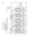
- FIG. 15shows a block diagram representation of array partitioning, in which data resident in LUNs 60 of the source virtual arrays 66 a , 66 b , 66 c , 66 d , and 66 e of the source array 16 a are migrated to respective destination virtual arrays 66 f , 66 g , 66 h , 66 L, and 66 m .
- These destination virtual arraysspan multiple physical destination storage arrays 16 b , 16 c .
- the combined number of virtual ports and number of LUNs 60 of the destination virtual arrays 66 f , 66 g , 66 h , 66 L, and 66 mare at least as many as the number of virtual ports and number of LUNs 60 of the source virtual arrays 66 a , 66 b , 66 c , 66 d , and 66 e .
- each LUN of the destination virtual arrays 66 f , 66 g , 66 h , 66 L, and 66 mis at least as large as its corresponding LUN of the respective source virtual arrays 66 a , 66 b , 66 c , 66 d , and 66 e.
- the source storage array 16 aBefore the array partitioning, the source storage array 16 a has a unique physical serial number 62 (here, e.g., 123456), and each source virtual array has a unique logical serial number (derived from the physical serial number), a gatekeeper 68 , array name, and IP address.
- the pre-transfer LUNs, array port names, gatekeepers, and logical serial numbers of the destination virtual arrays 66 f , 66 g , 66 h , 66 L, and 66 mare not shown in FIG. 15 .
- Emphasis insteadis placed on illustrating the results of partitioning data across the destination storage arrays 16 b , 16 c and destination virtual arrays 66 f , 66 g , 66 h , 66 L, and 66 m , rather than on any exchange aspect of the partitioning process.
- An exchangeis optional and is represented with phantom arrows from the destination virtual arrays to the source virtual arrays, although the results of this portion of the exchange are not represented in the source virtual arrays).
- a transfer from the source virtual arrays to the destination virtual arrays, rather than an exchangemay occur without departing from the principles of the invention.
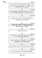
- FIG. 16shows an embodiment of an array partitioning process 200 for migrating data from the virtual arrays of the source storage array 16 a to the virtual arrays of multiple destination storage arrays 16 b , 16 c .
- the process 200occurs transparently to the hosts 12 , 18 and host applications 22 , 28 .
- the principles of the partitioning processcan apply to more than two destination storage arrays.
- the remote replication engine 126(of the source storage array 16 a ) copies the data resident at the LUNs of each source virtual array to the LUNs of a corresponding destination virtual array.
- data of the source virtual array 66 aare copied to the destination virtual array 66 f ; data of source virtual array 66 b , to the destination virtual array 66 g ; data of source virtual array 66 c , to the destination virtual array 66 h ; data of source virtual array 66 d , to the destination virtual array 66 L; and data of source virtual array 66 e , to the destination virtual array 66 m.
- select metadata at the source array 16 aare also migrated to the destination arrays 16 b , 16 c .
- the remote replication engine 126can access the metadata as metadata LUNs. Each metadata LUN is associated with one of the source virtual arrays 66 a , 66 b , 66 c , 66 d , 66 e . If the attribute of a metadata LUN so indicates, the remote replication engine 126 copies (step 204 ) that metadata LUN, for forwarding to one of the destination virtual arrays. The particular destination virtual array to which the metadata LUN is forwarded depends upon the particular source virtual array with which the metadata LUN is associated. In the illustrated example, metadata LUNs associated with the source virtual array 66 a are copied to metadata LUNs associated with the destination virtual array 66 f.
- each source virtual arraytransfers its Fibre Channel connection information to the corresponding destination virtual array.
- the connection information sent to a particular destination virtual arraycorresponds with the LUNs that have been migrated to that destination virtual array.
- the virtual port name/virtual port ID pair of (vn 0 , v 0 )passes from the source virtual array 66 a to the destination virtual array 66 f
- the virtual port name/virtual port ID pair of (vn 4 , v 4 )passes from the source virtual array 66 e to the destination virtual array 66 m .
- the LUN names and LUN numbers of the LUNs 60 a belonging to the source virtual array 66 abecome associated with the LUNs of the destination virtual array 66 f.
- each source virtual arraytransfers its associated management information (logical serial numbers, array names, and gatekeepers) to its corresponding destination virtual array.
- the source virtual array 66 asends its logical serial number, array name, and gatekeeper to the destination virtual array 66 f
- the destination virtual array 66 fsends its logical serial number, array name, and gatekeeper to the source virtual array 66 a .
- An exchange of management information between the source virtual arrays and their corresponding destination virtual arrays, rather than a one-way transfer,may occur without departing from the principles of the invention.
- switchoveris activated (step 210 ).
- the source storage array 16 a , one of the destination storage arrays 16 b , 16 c , or an administrator control stationcan then communicate (step 212 ) with the DNS server 26 to swap the IP addresses of each corresponding pair of source and destination virtual arrays, e.g., ( 66 a with 66 f ), ( 66 b with 66 g ), ( 66 c with 66 h ), ( 66 d with 66 L), and ( 66 e with 66 m ).
- the array names of each corresponding pair of source and destination virtual arraysare swapped in the array name table 24 .
- FIG. 17shows the array name table 24 and DNS table 106 before the array partitioning
- FIG. 18shows the array name table 24 and DNS table 106 after the appropriate pairs of array names are swapped within the array name table.
- the entries 100 for the source virtual arrays(SRC VARRAY A, SRC VARRAY B, SRC VARRAY C, SRC VARRAY D, and SRC VARRAY E) have been removed from the tables 24 , 106 .
- the source virtual arrayscan be removed because the destination virtual arrays (DEST A VARRAY F, DEST A VARRAY G, DEST A VARRAY H, DEST B VARRAY L, and DEST B VARRAY M) have each, in effect, replaced one of the source virtual arrays as a result of the partitioning.
- DEST A VARRAY F, DEST A VARRAY G, DEST A VARRAY H, DEST B VARRAY L, and DEST B VARRAY Mhave each, in effect, replaced one of the source virtual arrays as a result of the partitioning.
- FIG. 19shows an alternative to swapping array names in the array name table 24 : i.e., swapping appropriate pairs of IP addresses within the DNS table 106 , as described above.
- the entries for the destination virtual arrays(DEST A VARRAY F, DEST A VARRAY G, DEST A VARRAY H, DEST B VARRAY L, and DEST B VARRAY M) have been removed from the tables 24 , 106 in FIG. 19 .
- the management application 22continues to run as though accessing data at each of the source virtual arrays. For example, the management application 22 can continue to issue messages directed to serial number “123456A0” (previously associated with the source virtual array 66 a ). Because of the exchange of array names of the source and destination virtual arrays 66 a , 66 f in the array name table 24 , or of the exchange of IP addresses at the DNS server 26 , the management messages are addressed to the IP address of the destination virtual array 66 f after the switchover.
- the switch 14contains the name server, which reinitializes (step 214 ) the name-server database 70 .
- the name serveris separate from the switch 14 .
- the updated name-server databaseis uploaded (step 216 ) to the registered devices, including hosts 12 , 18 , and the hosts subsequently query (step 218 ) the destination virtual arrays using the LUN ID-LUN numbers.
- Upgrading or replacing data storagecan also involve migrating data from multiple source storage arrays to a single destination storage array (i.e., an N to 1 transfer).
- a data migration event involving the migration of arrays of data from multiple source arrays to a single destination arrayis referred to as array consolidation.
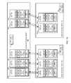
- FIG. 20shows a block diagram representation of array consolidation in which data resident at multiple source arrays 16 a , 16 b are migrated to a single destination array 16 g.
- Each source storage array 16 a , 16 bhas a plurality of virtual arrays: source storage array 16 a has source virtual arrays 66 a , 66 b , and 66 c ; source storage array 16 b has source virtual arrays 66 d , and 66 e .
- the destination storage array 16 ghas a plurality of virtual arrays 66 f , 66 g , 66 h , 66 L, and 66 m .
- the number of virtual ports and number of LUNs of the destination virtual arraysare at least as many as the combined number of virtual ports and number of LUNs of the source virtual arrays.
- the storage capacity of each LUN of the destination virtual arraysis as large as its corresponding LUN of the source virtual arrays.
- Each source and destination virtual array 66has a unique logical serial number, array name, gatekeeper, and IP address. Not shown in FIG. 20 are the pre-transfer LUNs, array port names, and logical serial number of the destination virtual arrays. Emphasis instead is placed on illustrating the results of consolidating data at the destination storage array 16 g , rather than on any exchange aspect of the consolidation process. Accordingly, FIG. 20 shows the results of the transfer of information from the source virtual arrays to the destination virtual arrays. (An exchange of information is optional and is represented with phantom arrows from the destination virtual arrays to the source virtual arrays, although the results of this portion of the exchange are not represented in the source virtual arrays). Notably, a transfer from the source virtual arrays to the destination virtual arrays, rather than an exchange, may occur without departing from the principles of the invention.
- FIG. 21shows an embodiment of process 250 for consolidating data resident at the source storage arrays 16 a , 16 b into the single destination array 16 g .
- the process 250executes transparently to the hosts 12 , 18 and host applications.
- the principles of the partitioning processapply to more than two source storage arrays.
- the remote replication engine 126 executing at the first source array 16 acopies data from each source virtual array 66 a , 66 b , 66 c to a corresponding destination virtual array 66 f , 66 g , and 66 h of the destination storage array 16 g .
- the remote replication engine 126 executing at the second source array 16 bcopies data from each source virtual array 66 d , 66 e to a corresponding destination virtual array 66 L, 66 m of the destination storage array 16 g .
- data of the source virtual array 66 aare copied to the destination virtual array 66 f ; data of source virtual array 66 b , to the destination virtual array 66 g ; data of source virtual array 66 c , to the destination virtual array 66 h ; data of source virtual array 66 d , to the destination virtual array 66 L; and data of source virtual array 66 e , to the destination virtual array 66 m.
- select metadata at the source arrays 16 a , 16 bare also migrated to the destination array 16 g .
- Each metadata LUNis associated with one of the source virtual arrays 66 a , 66 b , 66 c , 66 d , and 66 e .
- the remote replication engine 126 executing at each source array 16 a , 16 bdetermines whether to copy and forward (step 254 ) each metadata LUN associated with the source virtual arrays of the source array. For example, metadata LUNs that belong to the source virtual array 66 a are copied to metadata LUNs that belong to the destination virtual array 66 f , provided the attribute associated with each metadata LUN indicates that the metadata LUN is to be copied.
- each source virtual array 16 a , 16 btransfers its Fibre Channel connection information to the corresponding destination virtual array.
- the connection information sent to a particular destination virtual arraycorresponds with the LUNs that have been migrated to that destination virtual array.
- the virtual port name/virtual port ID pair of (vn 0 , v 0 )passes from the source virtual array 66 a (of source array 16 a ) to the destination virtual array 66 f
- the virtual port name/virtual port ID pair of (vn 4 , v 4 )passes from the source virtual array 66 e (of source array b) to the destination virtual array 66 m .
- the LUN names and LUN numbers of the LUNs 60 a belonging to the source virtual array 66 abecome associated with the LUNs of the destination virtual array 66 f.
- each source virtual arraytransfers its associated management information (logical serial numbers, array names, and gatekeepers) to its corresponding destination virtual array.
- the source virtual array 66 asends its logical serial number, array name, and gatekeeper to the destination virtual array 66 f
- the destination virtual array 66 fsends its logical serial number, array name, and gatekeeper to the source virtual array 66 a .
- An exchange of management information between the source virtual arrays and their corresponding destination virtual arrays, rather than a one-way transfer,may occur without departing from the principles of the invention.
- switchoveris activated (step 260 ).
- One of the source arrays 16 a , 16 b , destination array 16 g , or an administrator control stationcan then communicate (step 262 ) with the DNS server 26 to swap the IP address of each pair of corresponding source and destination virtual arrays e.g., ( 66 a with 66 f ), ( 66 b with 66 g ), ( 66 c with 66 h ), ( 66 d with 66 L), and ( 66 e with 66 m ).
- the array names of each corresponding pair of source and destination virtual arraysare swapped in the array name table 24 .
- FIG. 22shows the array name table 24 and DNS table 106 before the array consolidation
- FIG. 23shows the array name table 24 and DNS table 106 after the appropriate pairs of array names are swapped within the array name table 24 .
- the entries 100 for the source virtual arrays(SRC A VARRAY A, SRC A VARRAY B, SRC A VARRAY C, SRC B VARRAY D, and SRC B VARRAY E) have been removed from the tables 24 , 106 .
- source virtual arrayscan be removed because the destination virtual arrays (DEST VARRAY F, DEST VARRAY G, DEST VARRAY H, DEST VARRAY L, and DEST VARRAY M) have each, in effect, replaced one of the source virtual arrays as a result of the consolidation.
- DEST VARRAY F, DEST VARRAY G, DEST VARRAY H, DEST VARRAY L, and DEST VARRAY Mhave each, in effect, replaced one of the source virtual arrays as a result of the consolidation.
- FIG. 24shows an alternative to swapping array names: i.e., swapping appropriate pairs of IP addresses within the DNS table 106 , as described above.
- the entries for the destination virtual arrays(DEST A VARRAY F, DEST A VARRAY G, DEST A VARRAY H, DEST B VARRAY L, and DEST B VARRAY M) have been removed from the tables 24 , 106 in FIG. 24 .
- the management application 22continues to run as though accessing data at each of the source virtual arrays. For example, the management application 22 can continue to issue messages directed to serial number “123456A0” (previously associated with the source virtual array 66 a ). Because of the exchange of array names of the source and destination virtual arrays 66 a , 66 f in the array name table 24 , or of the exchange of IP addresses at the DNS server 26 , the management messages are addressed to the IP address of the destination virtual array 66 f after the switchover.
- the switch 14contains the name server, which reinitializes (step 264 ) the name-server database 70 .
- the name serveris separate from the switch 14 .
- the updated name-server databaseis uploaded (step 266 ) to the registered devices, including hosts 12 , 18 . Subsequently, the hosts query (step 268 ) the destination virtual arrays using the LUN ID-numbers.
- aspects of the present inventionmay be implemented, in whole or in part, as one or more computer-readable software programs embodied on or in one or more articles of manufacture.
- the article of manufacturecan be, for example, any one or combination of a floppy disk, a hard disk, hard-disk drive, a CD-ROM, a DVD-ROM, a flash memory card, an EEPROM, an EPROM, a PROM, a RAM, a ROM, or a magnetic tape.
- any standard or proprietary, programming or interpretive languagecan be used to produce the computer-readable software programs. Examples of such languages include C, C++, Pascal, JAVA, BASIC, Visual Basic, and Visual C++.
- the software programsmay be stored on or in one or more articles of manufacture as source code, object code, interpretive code, or executable code.
Landscapes
- Engineering & Computer Science (AREA)
- Theoretical Computer Science (AREA)
- Human Computer Interaction (AREA)
- Physics & Mathematics (AREA)
- General Engineering & Computer Science (AREA)
- General Physics & Mathematics (AREA)
- Information Retrieval, Db Structures And Fs Structures Therefor (AREA)
Abstract
Description
Claims (20)
Priority Applications (1)
| Application Number | Priority Date | Filing Date | Title |
|---|---|---|---|
| US11/427,731US8539177B1 (en) | 2006-06-29 | 2006-06-29 | Partitioning of a storage array into N-storage arrays using virtual array non-disruptive data migration |
Applications Claiming Priority (1)
| Application Number | Priority Date | Filing Date | Title |
|---|---|---|---|
| US11/427,731US8539177B1 (en) | 2006-06-29 | 2006-06-29 | Partitioning of a storage array into N-storage arrays using virtual array non-disruptive data migration |
Publications (1)
| Publication Number | Publication Date |
|---|---|
| US8539177B1true US8539177B1 (en) | 2013-09-17 |
Family
ID=49122526
Family Applications (1)
| Application Number | Title | Priority Date | Filing Date |
|---|---|---|---|
| US11/427,731Active2026-11-15US8539177B1 (en) | 2006-06-29 | 2006-06-29 | Partitioning of a storage array into N-storage arrays using virtual array non-disruptive data migration |
Country Status (1)
| Country | Link |
|---|---|
| US (1) | US8539177B1 (en) |
Cited By (122)
| Publication number | Priority date | Publication date | Assignee | Title |
|---|---|---|---|---|
| US20120278571A1 (en)* | 2011-04-26 | 2012-11-01 | International Business Machines Corporation | Migrating virtual machines across sites |
| US10817431B2 (en) | 2014-07-02 | 2020-10-27 | Pure Storage, Inc. | Distributed storage addressing |
| US10838633B2 (en) | 2014-06-04 | 2020-11-17 | Pure Storage, Inc. | Configurable hyperconverged multi-tenant storage system |
| US10942869B2 (en) | 2017-03-30 | 2021-03-09 | Pure Storage, Inc. | Efficient coding in a storage system |
| US11030090B2 (en) | 2016-07-26 | 2021-06-08 | Pure Storage, Inc. | Adaptive data migration |
| US11074016B2 (en) | 2017-10-31 | 2021-07-27 | Pure Storage, Inc. | Using flash storage devices with different sized erase blocks |
| US11079962B2 (en) | 2014-07-02 | 2021-08-03 | Pure Storage, Inc. | Addressable non-volatile random access memory |
| US11086532B2 (en) | 2017-10-31 | 2021-08-10 | Pure Storage, Inc. | Data rebuild with changing erase block sizes |
| US11138082B2 (en) | 2014-06-04 | 2021-10-05 | Pure Storage, Inc. | Action determination based on redundancy level |
| US11144212B2 (en) | 2015-04-10 | 2021-10-12 | Pure Storage, Inc. | Independent partitions within an array |
| US11190580B2 (en) | 2017-07-03 | 2021-11-30 | Pure Storage, Inc. | Stateful connection resets |
| US11188476B1 (en) | 2014-08-20 | 2021-11-30 | Pure Storage, Inc. | Virtual addressing in a storage system |
| US11204830B2 (en) | 2014-08-07 | 2021-12-21 | Pure Storage, Inc. | Die-level monitoring in a storage cluster |
| US11204701B2 (en) | 2015-12-22 | 2021-12-21 | Pure Storage, Inc. | Token based transactions |
| US11240307B2 (en) | 2015-04-09 | 2022-02-01 | Pure Storage, Inc. | Multiple communication paths in a storage system |
| US11281394B2 (en) | 2019-06-24 | 2022-03-22 | Pure Storage, Inc. | Replication across partitioning schemes in a distributed storage system |
| US11289169B2 (en) | 2017-01-13 | 2022-03-29 | Pure Storage, Inc. | Cycled background reads |
| US11310317B1 (en) | 2014-06-04 | 2022-04-19 | Pure Storage, Inc. | Efficient load balancing |
| US11307998B2 (en) | 2017-01-09 | 2022-04-19 | Pure Storage, Inc. | Storage efficiency of encrypted host system data |
| US11340821B2 (en) | 2016-07-26 | 2022-05-24 | Pure Storage, Inc. | Adjustable migration utilization |
| US11354058B2 (en) | 2018-09-06 | 2022-06-07 | Pure Storage, Inc. | Local relocation of data stored at a storage device of a storage system |
| US11385799B2 (en) | 2014-06-04 | 2022-07-12 | Pure Storage, Inc. | Storage nodes supporting multiple erasure coding schemes |
| US11385979B2 (en) | 2014-07-02 | 2022-07-12 | Pure Storage, Inc. | Mirrored remote procedure call cache |
| US11392522B2 (en) | 2014-07-03 | 2022-07-19 | Pure Storage, Inc. | Transfer of segmented data |
| US11409437B2 (en) | 2016-07-22 | 2022-08-09 | Pure Storage, Inc. | Persisting configuration information |
| US11416144B2 (en) | 2019-12-12 | 2022-08-16 | Pure Storage, Inc. | Dynamic use of segment or zone power loss protection in a flash device |
| US11442625B2 (en) | 2014-08-07 | 2022-09-13 | Pure Storage, Inc. | Multiple read data paths in a storage system |
| US11442645B2 (en) | 2018-01-31 | 2022-09-13 | Pure Storage, Inc. | Distributed storage system expansion mechanism |
| US11489668B2 (en) | 2015-09-30 | 2022-11-01 | Pure Storage, Inc. | Secret regeneration in a storage system |
| US11494498B2 (en) | 2014-07-03 | 2022-11-08 | Pure Storage, Inc. | Storage data decryption |
| US20220357866A1 (en)* | 2021-05-06 | 2022-11-10 | EMC IP Holding Company LLC | Method for reassembling local disk managers and array groups |
| US11507597B2 (en) | 2021-03-31 | 2022-11-22 | Pure Storage, Inc. | Data replication to meet a recovery point objective |
| US11544143B2 (en) | 2014-08-07 | 2023-01-03 | Pure Storage, Inc. | Increased data reliability |
| US11550752B2 (en) | 2014-07-03 | 2023-01-10 | Pure Storage, Inc. | Administrative actions via a reserved filename |
| US11550473B2 (en) | 2016-05-03 | 2023-01-10 | Pure Storage, Inc. | High-availability storage array |
| US11567917B2 (en) | 2015-09-30 | 2023-01-31 | Pure Storage, Inc. | Writing data and metadata into storage |
| US11582046B2 (en) | 2015-10-23 | 2023-02-14 | Pure Storage, Inc. | Storage system communication |
| US11593203B2 (en) | 2014-06-04 | 2023-02-28 | Pure Storage, Inc. | Coexisting differing erasure codes |
| US11592985B2 (en) | 2017-04-05 | 2023-02-28 | Pure Storage, Inc. | Mapping LUNs in a storage memory |
| US11604598B2 (en) | 2014-07-02 | 2023-03-14 | Pure Storage, Inc. | Storage cluster with zoned drives |
| US11604690B2 (en) | 2016-07-24 | 2023-03-14 | Pure Storage, Inc. | Online failure span determination |
| US11614880B2 (en) | 2020-12-31 | 2023-03-28 | Pure Storage, Inc. | Storage system with selectable write paths |
| US11620197B2 (en) | 2014-08-07 | 2023-04-04 | Pure Storage, Inc. | Recovering error corrected data |
| US11650976B2 (en) | 2011-10-14 | 2023-05-16 | Pure Storage, Inc. | Pattern matching using hash tables in storage system |
| US11652884B2 (en) | 2014-06-04 | 2023-05-16 | Pure Storage, Inc. | Customized hash algorithms |
| US11656768B2 (en) | 2016-09-15 | 2023-05-23 | Pure Storage, Inc. | File deletion in a distributed system |
| US11656961B2 (en) | 2020-02-28 | 2023-05-23 | Pure Storage, Inc. | Deallocation within a storage system |
| US11675762B2 (en) | 2015-06-26 | 2023-06-13 | Pure Storage, Inc. | Data structures for key management |
| US11704192B2 (en) | 2019-12-12 | 2023-07-18 | Pure Storage, Inc. | Budgeting open blocks based on power loss protection |
| US11704073B2 (en) | 2015-07-13 | 2023-07-18 | Pure Storage, Inc | Ownership determination for accessing a file |
| US11714708B2 (en) | 2017-07-31 | 2023-08-01 | Pure Storage, Inc. | Intra-device redundancy scheme |
| US11722455B2 (en) | 2017-04-27 | 2023-08-08 | Pure Storage, Inc. | Storage cluster address resolution |
| US11734169B2 (en) | 2016-07-26 | 2023-08-22 | Pure Storage, Inc. | Optimizing spool and memory space management |
| US11740802B2 (en) | 2015-09-01 | 2023-08-29 | Pure Storage, Inc. | Error correction bypass for erased pages |
| US11741003B2 (en) | 2017-11-17 | 2023-08-29 | Pure Storage, Inc. | Write granularity for storage system |
| US11775428B2 (en) | 2015-03-26 | 2023-10-03 | Pure Storage, Inc. | Deletion immunity for unreferenced data |
| US11775491B2 (en) | 2020-04-24 | 2023-10-03 | Pure Storage, Inc. | Machine learning model for storage system |
| US11782625B2 (en) | 2017-06-11 | 2023-10-10 | Pure Storage, Inc. | Heterogeneity supportive resiliency groups |
| US11789626B2 (en) | 2020-12-17 | 2023-10-17 | Pure Storage, Inc. | Optimizing block allocation in a data storage system |
| US11797212B2 (en) | 2016-07-26 | 2023-10-24 | Pure Storage, Inc. | Data migration for zoned drives |
| US11822444B2 (en) | 2014-06-04 | 2023-11-21 | Pure Storage, Inc. | Data rebuild independent of error detection |
| US11836348B2 (en) | 2018-04-27 | 2023-12-05 | Pure Storage, Inc. | Upgrade for system with differing capacities |
| US11842053B2 (en) | 2016-12-19 | 2023-12-12 | Pure Storage, Inc. | Zone namespace |
| US11846968B2 (en) | 2018-09-06 | 2023-12-19 | Pure Storage, Inc. | Relocation of data for heterogeneous storage systems |
| US11847324B2 (en) | 2020-12-31 | 2023-12-19 | Pure Storage, Inc. | Optimizing resiliency groups for data regions of a storage system |
| US11847331B2 (en) | 2019-12-12 | 2023-12-19 | Pure Storage, Inc. | Budgeting open blocks of a storage unit based on power loss prevention |
| US11847013B2 (en) | 2018-02-18 | 2023-12-19 | Pure Storage, Inc. | Readable data determination |
| US11861188B2 (en) | 2016-07-19 | 2024-01-02 | Pure Storage, Inc. | System having modular accelerators |
| US11869583B2 (en) | 2017-04-27 | 2024-01-09 | Pure Storage, Inc. | Page write requirements for differing types of flash memory |
| US11868309B2 (en) | 2018-09-06 | 2024-01-09 | Pure Storage, Inc. | Queue management for data relocation |
| US11886334B2 (en) | 2016-07-26 | 2024-01-30 | Pure Storage, Inc. | Optimizing spool and memory space management |
| US11886308B2 (en) | 2014-07-02 | 2024-01-30 | Pure Storage, Inc. | Dual class of service for unified file and object messaging |
| US11886288B2 (en) | 2016-07-22 | 2024-01-30 | Pure Storage, Inc. | Optimize data protection layouts based on distributed flash wear leveling |
| US11893023B2 (en) | 2015-09-04 | 2024-02-06 | Pure Storage, Inc. | Deterministic searching using compressed indexes |
| US11893126B2 (en) | 2019-10-14 | 2024-02-06 | Pure Storage, Inc. | Data deletion for a multi-tenant environment |
| US11899582B2 (en) | 2019-04-12 | 2024-02-13 | Pure Storage, Inc. | Efficient memory dump |
| US11922070B2 (en) | 2016-10-04 | 2024-03-05 | Pure Storage, Inc. | Granting access to a storage device based on reservations |
| US11955187B2 (en) | 2017-01-13 | 2024-04-09 | Pure Storage, Inc. | Refresh of differing capacity NAND |
| US11960371B2 (en) | 2014-06-04 | 2024-04-16 | Pure Storage, Inc. | Message persistence in a zoned system |
| US11966841B2 (en) | 2018-01-31 | 2024-04-23 | Pure Storage, Inc. | Search acceleration for artificial intelligence |
| US11971828B2 (en) | 2015-09-30 | 2024-04-30 | Pure Storage, Inc. | Logic module for use with encoded instructions |
| US11995318B2 (en) | 2016-10-28 | 2024-05-28 | Pure Storage, Inc. | Deallocated block determination |
| US12001700B2 (en) | 2018-10-26 | 2024-06-04 | Pure Storage, Inc. | Dynamically selecting segment heights in a heterogeneous RAID group |
| US12032724B2 (en) | 2017-08-31 | 2024-07-09 | Pure Storage, Inc. | Encryption in a storage array |
| US12038927B2 (en) | 2015-09-04 | 2024-07-16 | Pure Storage, Inc. | Storage system having multiple tables for efficient searching |
| US12046292B2 (en) | 2017-10-31 | 2024-07-23 | Pure Storage, Inc. | Erase blocks having differing sizes |
| US12050774B2 (en) | 2015-05-27 | 2024-07-30 | Pure Storage, Inc. | Parallel update for a distributed system |
| US12056365B2 (en) | 2020-04-24 | 2024-08-06 | Pure Storage, Inc. | Resiliency for a storage system |
| US12061814B2 (en) | 2021-01-25 | 2024-08-13 | Pure Storage, Inc. | Using data similarity to select segments for garbage collection |
| US12067282B2 (en) | 2020-12-31 | 2024-08-20 | Pure Storage, Inc. | Write path selection |
| US12067274B2 (en) | 2018-09-06 | 2024-08-20 | Pure Storage, Inc. | Writing segments and erase blocks based on ordering |
| US12079494B2 (en) | 2018-04-27 | 2024-09-03 | Pure Storage, Inc. | Optimizing storage system upgrades to preserve resources |
| US12079125B2 (en) | 2019-06-05 | 2024-09-03 | Pure Storage, Inc. | Tiered caching of data in a storage system |
| US12086472B2 (en) | 2015-03-27 | 2024-09-10 | Pure Storage, Inc. | Heterogeneous storage arrays |
| US12093545B2 (en) | 2020-12-31 | 2024-09-17 | Pure Storage, Inc. | Storage system with selectable write modes |
| US12105620B2 (en) | 2016-10-04 | 2024-10-01 | Pure Storage, Inc. | Storage system buffering |
| US12135878B2 (en) | 2019-01-23 | 2024-11-05 | Pure Storage, Inc. | Programming frequently read data to low latency portions of a solid-state storage array |
| US12137140B2 (en) | 2014-06-04 | 2024-11-05 | Pure Storage, Inc. | Scale out storage platform having active failover |
| US12141118B2 (en) | 2016-10-04 | 2024-11-12 | Pure Storage, Inc. | Optimizing storage system performance using data characteristics |
| US12158814B2 (en) | 2014-08-07 | 2024-12-03 | Pure Storage, Inc. | Granular voltage tuning |
| US12182044B2 (en) | 2014-07-03 | 2024-12-31 | Pure Storage, Inc. | Data storage in a zone drive |
| US12197390B2 (en) | 2017-11-20 | 2025-01-14 | Pure Storage, Inc. | Locks in a distributed file system |
| US12204768B2 (en) | 2019-12-03 | 2025-01-21 | Pure Storage, Inc. | Allocation of blocks based on power loss protection |
| US12204788B1 (en) | 2023-07-21 | 2025-01-21 | Pure Storage, Inc. | Dynamic plane selection in data storage system |
| US12204413B2 (en) | 2017-06-07 | 2025-01-21 | Pure Storage, Inc. | Snapshot commitment in a distributed system |
| US12212624B2 (en) | 2014-06-04 | 2025-01-28 | Pure Storage, Inc. | Independent communication pathways |
| US12216903B2 (en) | 2016-10-31 | 2025-02-04 | Pure Storage, Inc. | Storage node data placement utilizing similarity |
| US12229437B2 (en) | 2020-12-31 | 2025-02-18 | Pure Storage, Inc. | Dynamic buffer for storage system |
| US12235743B2 (en) | 2016-06-03 | 2025-02-25 | Pure Storage, Inc. | Efficient partitioning for storage system resiliency groups |
| US12242425B2 (en) | 2017-10-04 | 2025-03-04 | Pure Storage, Inc. | Similarity data for reduced data usage |
| US12271359B2 (en) | 2015-09-30 | 2025-04-08 | Pure Storage, Inc. | Device host operations in a storage system |
| US12282799B2 (en) | 2015-05-19 | 2025-04-22 | Pure Storage, Inc. | Maintaining coherency in a distributed system |
| US12314170B2 (en) | 2020-07-08 | 2025-05-27 | Pure Storage, Inc. | Guaranteeing physical deletion of data in a storage system |
| US12314163B2 (en) | 2022-04-21 | 2025-05-27 | Pure Storage, Inc. | Die-aware scheduler |
| US12341848B2 (en) | 2014-06-04 | 2025-06-24 | Pure Storage, Inc. | Distributed protocol endpoint services for data storage systems |
| US12340107B2 (en) | 2016-05-02 | 2025-06-24 | Pure Storage, Inc. | Deduplication selection and optimization |
| US12373340B2 (en) | 2019-04-03 | 2025-07-29 | Pure Storage, Inc. | Intelligent subsegment formation in a heterogeneous storage system |
| US12379854B2 (en) | 2015-04-10 | 2025-08-05 | Pure Storage, Inc. | Two or more logical arrays having zoned drives |
| US12393340B2 (en) | 2019-01-16 | 2025-08-19 | Pure Storage, Inc. | Latency reduction of flash-based devices using programming interrupts |
| US12430059B2 (en) | 2020-04-15 | 2025-09-30 | Pure Storage, Inc. | Tuning storage devices |
| US12430053B2 (en) | 2021-03-12 | 2025-09-30 | Pure Storage, Inc. | Data block allocation for storage system |
| US12439544B2 (en) | 2022-04-20 | 2025-10-07 | Pure Storage, Inc. | Retractable pivoting trap door |
Citations (53)
| Publication number | Priority date | Publication date | Assignee | Title |
|---|---|---|---|---|
| US5247632A (en) | 1989-01-23 | 1993-09-21 | Eastman Kodak Company | Virtual memory management arrangement for addressing multi-dimensional arrays in a digital data processing system |
| US5568629A (en)* | 1991-12-23 | 1996-10-22 | At&T Global Information Solutions Company | Method for partitioning disk drives within a physical disk array and selectively assigning disk drive partitions into a logical disk array |
| US5963555A (en) | 1996-09-03 | 1999-10-05 | Hitachi Ltd | Router apparatus using ATM switch |
| EP1130514A2 (en) | 2000-03-03 | 2001-09-05 | Hitachi, Ltd. | Data migration method using storage area network |
| US6336152B1 (en) | 1994-05-27 | 2002-01-01 | Microsoft Corporation | Method for automatically configuring devices including a network adapter without manual intervention and without prior configuration information |
| US20020071386A1 (en) | 2000-12-07 | 2002-06-13 | Gronke Edward P. | Technique to provide automatic failover for channel-based communications |
| US6421711B1 (en) | 1998-06-29 | 2002-07-16 | Emc Corporation | Virtual ports for data transferring of a data storage system |
| US20020165982A1 (en) | 2001-04-18 | 2002-11-07 | Jerrold Leichter | Implementing managed network services for customers with duplicate IP networks |
| US20030018927A1 (en) | 2001-07-23 | 2003-01-23 | Gadir Omar M.A. | High-availability cluster virtual server system |
| US6563834B1 (en) | 1998-07-31 | 2003-05-13 | Fujitsu Limited | Network path controlling method and apparatus |
| US20030131182A1 (en)* | 2002-01-09 | 2003-07-10 | Andiamo Systems | Methods and apparatus for implementing virtualization of storage within a storage area network through a virtual enclosure |
| WO2003062979A2 (en) | 2002-01-23 | 2003-07-31 | Cisco Technology, Inc. | Methods and apparatus for implementing virtualization of storage within a storage area network |
| EP1357465A2 (en) | 2002-04-26 | 2003-10-29 | Hitachi, Ltd. | Storage system having virtualized resource |
| US6684209B1 (en) | 2000-01-14 | 2004-01-27 | Hitachi, Ltd. | Security method and system for storage subsystem |
| US20040139240A1 (en) | 2003-01-15 | 2004-07-15 | Hewlett-Packard Company | Storage system with LUN virtualization |
| US20040151188A1 (en) | 2003-01-31 | 2004-08-05 | Brocade Communications Systems, Inc. | Method and apparatus for providing virtual ports with attached virtual devices in a storage area network |
| US20040177228A1 (en)* | 2001-06-11 | 2004-09-09 | Leonhardt Michael L. | Outboard data storage management system and method |
| US20040213272A1 (en) | 2003-03-28 | 2004-10-28 | Shinjiro Nishi | Layer 2 switching device |
| US20040243710A1 (en) | 2001-08-03 | 2004-12-02 | Xiaolei Mao | Method of user data exchange in the data network and a data network |
| US6839750B1 (en) | 2001-03-03 | 2005-01-04 | Emc Corporation | Single management point for a storage system or storage area network |
| US20050010688A1 (en) | 2003-06-17 | 2005-01-13 | Hitachi, Ltd. | Management device for name of virtual port |
| US20050008016A1 (en) | 2003-06-18 | 2005-01-13 | Hitachi, Ltd. | Network system and its switches |
| US20050015415A1 (en) | 2003-07-14 | 2005-01-20 | International Business Machines Corporation | Method, system, and program for performing an input/output operation with respect to a logical storage device |
| US20050120160A1 (en) | 2003-08-20 | 2005-06-02 | Jerry Plouffe | System and method for managing virtual servers |
| US6907505B2 (en)* | 2002-07-31 | 2005-06-14 | Hewlett-Packard Development Company, L.P. | Immediately available, statically allocated, full-logical-unit copy with a transient, snapshot-copy-like intermediate stage |
| US20050154849A1 (en) | 2004-01-13 | 2005-07-14 | Naoki Watanabe | Data-migration method |
| US20050204104A1 (en)* | 2004-03-15 | 2005-09-15 | Tatsundo Aoshima | Server and method for managing volume storing digital archive |
| US20050243611A1 (en) | 2002-03-26 | 2005-11-03 | Clark Lubbers | Flexible data replication mechanism |
| US20050251620A1 (en) | 2004-05-10 | 2005-11-10 | Hitachi, Ltd. | Data migration in storage system |
| US20060041595A1 (en) | 2004-08-19 | 2006-02-23 | Hitachi, Ltd. | Storage network migration method, management device, management program and storage network system |
| US20060047930A1 (en)* | 2004-08-30 | 2006-03-02 | Toru Takahashi | Storage system and data relocation control device |
| US20060064466A1 (en)* | 2004-09-22 | 2006-03-23 | Kenta Shiga | Data migration method |
| US20060075005A1 (en) | 2004-02-24 | 2006-04-06 | Hitachi, Ltd. | Method and apparatus of media management on disk-subsystem |
| US20060080516A1 (en) | 2004-10-12 | 2006-04-13 | Paveza John R | Apparatus, system, and method for copy protection |
| US7043663B1 (en) | 2001-11-15 | 2006-05-09 | Xiotech Corporation | System and method to monitor and isolate faults in a storage area network |
| US20060107010A1 (en)* | 2004-11-18 | 2006-05-18 | Hitachi, Ltd. | Storage system and data migration method of storage system |
| US7051101B1 (en) | 2000-09-13 | 2006-05-23 | Emc Corporation | Methods and apparatus for controlling devices within storage network |
| US20060155777A1 (en) | 2004-12-03 | 2006-07-13 | Oracle International Corporation | Deployment of life-cycle model for LDAP applications |
| US20060190698A1 (en) | 2005-02-23 | 2006-08-24 | Jun Mizuno | Network system and method for setting volume group in the network system |
| US7120728B2 (en) | 2002-07-31 | 2006-10-10 | Brocade Communications Systems, Inc. | Hardware-based translating virtualization switch |
| US7124143B2 (en) | 2004-05-10 | 2006-10-17 | Hitachi, Ltd. | Data migration in storage system |
| US7260737B1 (en) | 2003-04-23 | 2007-08-21 | Network Appliance, Inc. | System and method for transport-level failover of FCP devices in a cluster |
| US20070220310A1 (en) | 2006-02-16 | 2007-09-20 | Cisco Technology, Inc. | Apparatus and methods for an appliance to synchronize with a storage device |
| US20070234342A1 (en) | 2006-01-25 | 2007-10-04 | Flynn John T Jr | System and method for relocating running applications to topologically remotely located computing systems |
| US20070266212A1 (en) | 2006-04-17 | 2007-11-15 | Hitachi, Ltd. | Data transfer method and information processing apparatus |
| US20070291785A1 (en) | 2006-06-16 | 2007-12-20 | Cisco Technology, Inc. | Fibre channel dynamic zoning |
| US20080005468A1 (en) | 2006-05-08 | 2008-01-03 | Sorin Faibish | Storage array virtualization using a storage block mapping protocol client and server |
| US7318120B2 (en) | 2002-07-19 | 2008-01-08 | Hewlett-Packard Development Company, L.P. | Hardware assisted communication between processors |
| US7340639B1 (en) | 2004-01-08 | 2008-03-04 | Network Appliance, Inc. | System and method for proxying data access commands in a clustered storage system |
| US20080086608A1 (en) | 2006-10-10 | 2008-04-10 | Hitachi, Ltd. | System and method for migration of CDP journal data between storage subsystems |
| US7366846B2 (en) | 2005-01-14 | 2008-04-29 | International Business Machines Corporation | Redirection of storage access requests |
| US7398421B1 (en) | 2004-12-03 | 2008-07-08 | Symantec Operating Corporation | System and method for storage area network switch port failure recovery |
| US7500134B2 (en) | 2005-12-27 | 2009-03-03 | Emc Corporation | Virtual array failover |
- 2006
- 2006-06-29USUS11/427,731patent/US8539177B1/enactiveActive
Patent Citations (58)
| Publication number | Priority date | Publication date | Assignee | Title |
|---|---|---|---|---|
| US5247632A (en) | 1989-01-23 | 1993-09-21 | Eastman Kodak Company | Virtual memory management arrangement for addressing multi-dimensional arrays in a digital data processing system |
| US5568629A (en)* | 1991-12-23 | 1996-10-22 | At&T Global Information Solutions Company | Method for partitioning disk drives within a physical disk array and selectively assigning disk drive partitions into a logical disk array |
| US6336152B1 (en) | 1994-05-27 | 2002-01-01 | Microsoft Corporation | Method for automatically configuring devices including a network adapter without manual intervention and without prior configuration information |
| US5963555A (en) | 1996-09-03 | 1999-10-05 | Hitachi Ltd | Router apparatus using ATM switch |
| US6421711B1 (en) | 1998-06-29 | 2002-07-16 | Emc Corporation | Virtual ports for data transferring of a data storage system |
| US20040054866A1 (en) | 1998-06-29 | 2004-03-18 | Blumenau Steven M. | Mapping of hosts to logical storage units and data storage ports in a data processing system |
| US6563834B1 (en) | 1998-07-31 | 2003-05-13 | Fujitsu Limited | Network path controlling method and apparatus |
| US6684209B1 (en) | 2000-01-14 | 2004-01-27 | Hitachi, Ltd. | Security method and system for storage subsystem |
| US20040133576A1 (en) | 2000-01-14 | 2004-07-08 | Hitachi, Ltd. | Security method and system for storage subsystem |
| EP1130514A2 (en) | 2000-03-03 | 2001-09-05 | Hitachi, Ltd. | Data migration method using storage area network |
| US7051101B1 (en) | 2000-09-13 | 2006-05-23 | Emc Corporation | Methods and apparatus for controlling devices within storage network |
| US20020071386A1 (en) | 2000-12-07 | 2002-06-13 | Gronke Edward P. | Technique to provide automatic failover for channel-based communications |
| US6839750B1 (en) | 2001-03-03 | 2005-01-04 | Emc Corporation | Single management point for a storage system or storage area network |
| US7383357B2 (en) | 2001-04-18 | 2008-06-03 | Emc Corporation | Implementing managed network services for customers with duplicate IP networks |
| US20020165982A1 (en) | 2001-04-18 | 2002-11-07 | Jerrold Leichter | Implementing managed network services for customers with duplicate IP networks |
| US20040177228A1 (en)* | 2001-06-11 | 2004-09-09 | Leonhardt Michael L. | Outboard data storage management system and method |
| US20030018927A1 (en) | 2001-07-23 | 2003-01-23 | Gadir Omar M.A. | High-availability cluster virtual server system |
| US6944785B2 (en) | 2001-07-23 | 2005-09-13 | Network Appliance, Inc. | High-availability cluster virtual server system |
| US20040243710A1 (en) | 2001-08-03 | 2004-12-02 | Xiaolei Mao | Method of user data exchange in the data network and a data network |
| US7043663B1 (en) | 2001-11-15 | 2006-05-09 | Xiotech Corporation | System and method to monitor and isolate faults in a storage area network |
| US20030131182A1 (en)* | 2002-01-09 | 2003-07-10 | Andiamo Systems | Methods and apparatus for implementing virtualization of storage within a storage area network through a virtual enclosure |
| WO2003062979A2 (en) | 2002-01-23 | 2003-07-31 | Cisco Technology, Inc. | Methods and apparatus for implementing virtualization of storage within a storage area network |
| US7433948B2 (en) | 2002-01-23 | 2008-10-07 | Cisco Technology, Inc. | Methods and apparatus for implementing virtualization of storage within a storage area network |
| US20050243611A1 (en) | 2002-03-26 | 2005-11-03 | Clark Lubbers | Flexible data replication mechanism |
| EP1357465A2 (en) | 2002-04-26 | 2003-10-29 | Hitachi, Ltd. | Storage system having virtualized resource |
| US7318120B2 (en) | 2002-07-19 | 2008-01-08 | Hewlett-Packard Development Company, L.P. | Hardware assisted communication between processors |
| US7120728B2 (en) | 2002-07-31 | 2006-10-10 | Brocade Communications Systems, Inc. | Hardware-based translating virtualization switch |
| US6907505B2 (en)* | 2002-07-31 | 2005-06-14 | Hewlett-Packard Development Company, L.P. | Immediately available, statically allocated, full-logical-unit copy with a transient, snapshot-copy-like intermediate stage |
| US20040139240A1 (en) | 2003-01-15 | 2004-07-15 | Hewlett-Packard Company | Storage system with LUN virtualization |
| US20040151188A1 (en) | 2003-01-31 | 2004-08-05 | Brocade Communications Systems, Inc. | Method and apparatus for providing virtual ports with attached virtual devices in a storage area network |
| US20040213272A1 (en) | 2003-03-28 | 2004-10-28 | Shinjiro Nishi | Layer 2 switching device |
| US7260737B1 (en) | 2003-04-23 | 2007-08-21 | Network Appliance, Inc. | System and method for transport-level failover of FCP devices in a cluster |
| US20050010688A1 (en) | 2003-06-17 | 2005-01-13 | Hitachi, Ltd. | Management device for name of virtual port |
| US20050008016A1 (en) | 2003-06-18 | 2005-01-13 | Hitachi, Ltd. | Network system and its switches |
| US20050015415A1 (en) | 2003-07-14 | 2005-01-20 | International Business Machines Corporation | Method, system, and program for performing an input/output operation with respect to a logical storage device |
| US20050120160A1 (en) | 2003-08-20 | 2005-06-02 | Jerry Plouffe | System and method for managing virtual servers |
| US7340639B1 (en) | 2004-01-08 | 2008-03-04 | Network Appliance, Inc. | System and method for proxying data access commands in a clustered storage system |
| US20050154849A1 (en) | 2004-01-13 | 2005-07-14 | Naoki Watanabe | Data-migration method |
| US20060075005A1 (en) | 2004-02-24 | 2006-04-06 | Hitachi, Ltd. | Method and apparatus of media management on disk-subsystem |
| US20050204104A1 (en)* | 2004-03-15 | 2005-09-15 | Tatsundo Aoshima | Server and method for managing volume storing digital archive |
| US7124143B2 (en) | 2004-05-10 | 2006-10-17 | Hitachi, Ltd. | Data migration in storage system |
| US20050251620A1 (en) | 2004-05-10 | 2005-11-10 | Hitachi, Ltd. | Data migration in storage system |
| US20060041595A1 (en) | 2004-08-19 | 2006-02-23 | Hitachi, Ltd. | Storage network migration method, management device, management program and storage network system |
| US20060047930A1 (en)* | 2004-08-30 | 2006-03-02 | Toru Takahashi | Storage system and data relocation control device |
| US20060064466A1 (en)* | 2004-09-22 | 2006-03-23 | Kenta Shiga | Data migration method |
| US20060080516A1 (en) | 2004-10-12 | 2006-04-13 | Paveza John R | Apparatus, system, and method for copy protection |
| US20060107010A1 (en)* | 2004-11-18 | 2006-05-18 | Hitachi, Ltd. | Storage system and data migration method of storage system |
| US20060155777A1 (en) | 2004-12-03 | 2006-07-13 | Oracle International Corporation | Deployment of life-cycle model for LDAP applications |
| US7398421B1 (en) | 2004-12-03 | 2008-07-08 | Symantec Operating Corporation | System and method for storage area network switch port failure recovery |
| US7366846B2 (en) | 2005-01-14 | 2008-04-29 | International Business Machines Corporation | Redirection of storage access requests |
| US20060190698A1 (en) | 2005-02-23 | 2006-08-24 | Jun Mizuno | Network system and method for setting volume group in the network system |
| US7500134B2 (en) | 2005-12-27 | 2009-03-03 | Emc Corporation | Virtual array failover |
| US20070234342A1 (en) | 2006-01-25 | 2007-10-04 | Flynn John T Jr | System and method for relocating running applications to topologically remotely located computing systems |
| US20070220310A1 (en) | 2006-02-16 | 2007-09-20 | Cisco Technology, Inc. | Apparatus and methods for an appliance to synchronize with a storage device |
| US20070266212A1 (en) | 2006-04-17 | 2007-11-15 | Hitachi, Ltd. | Data transfer method and information processing apparatus |
| US20080005468A1 (en) | 2006-05-08 | 2008-01-03 | Sorin Faibish | Storage array virtualization using a storage block mapping protocol client and server |
| US20070291785A1 (en) | 2006-06-16 | 2007-12-20 | Cisco Technology, Inc. | Fibre channel dynamic zoning |
| US20080086608A1 (en) | 2006-10-10 | 2008-04-10 | Hitachi, Ltd. | System and method for migration of CDP journal data between storage subsystems |
Non-Patent Citations (58)
| Title |
|---|
| Brown, et al.; U.S. Appl. No. 11/427,646, filed Jun. 29, 2006; 47 pages. |
| Charles Millilgan et al., Online Storage Virtualization: The key to managing the data explosion, Proceedings of the 35th Hawaii International Conference on System Sciences, 2002, IEEE. |
| Final Office Action mailed Dec. 14, 2009 for U.S. Appl. No. 11/427,744. |
| Final Office Action mailed Dec. 14, 2009 for U.S. Appl. No. 11/427,749. |
| Final Office Action mailed Dec. 2, 2009 for U.S. Appl. No. 11/427,759. |
| Final Office Action mailed Feb. 22, 2010 for U.S. Appl. No. 11/318,757. |
| Final Office Action mailed Jul. 2, 2010 for U.S. Appl. No. 11/771,604. |
| Final Office Action mailed Jun. 23, 2010 for U.S. Appl. No. 11/771,686. |
| Final Office Action mailed Oct. 21, 2009 for U.S. Appl. No. 11/318,734. |
| Final Office Action mailed Oct. 28, 2009 for U.S. Appl. No. 11/318,719. |
| Final Office Action mailed Sep. 17, 2008 for U.S. Appl. No. 11/427,749. |
| Madnani, et al.; U.S. Appl. No. 11/427,744, filed Jun. 29, 2006; 83 pages. |
| Madnani; U.S. Appl. No. 11/318,675, filed Dec. 27, 2005; 90 pages. |
| Madnani; U.S. Appl. No. 11/318,757, filed Dec. 27, 2005; 35 pages. |
| Notice of Allowance in related U.S. Appl. No. 11/427,744, mailed on Apr. 12, 2013; 12 pages. |
| Notice of Allowance in related U.S. Appl. No. 11/427,744, mailed on Jul. 5, 2013; 20 pages. |
| Notice of Allowance in related U.S. Appl. No. 11/427,749, mailed on Dec. 18, 2012; 5 pages. |
| Notice of Allowance mailed Dec. 11, 2009 for U.S. Appl. No. 11/318,734. |
| Notice of Allowance mailed Dec. 3, 2009 for U.S. Appl. No. 11/318,719. |
| Notice of Allowance mailed Jun. 12, 2008 for U.S. Appl. No. 11/318,675. |
| Notice of Allowance mailed Mar. 6, 2010 for U.S. Appl. No. 11/427,724. |
| Notice of Allowance mailed Nov. 16, 2009 for U.S. Appl. No. 11/427,646. |
| Ofer, et al.; U.S. Appl. No. 11/427,724, filed Jun. 29, 2006; 78 pages. |
| Ofer, et al.; U.S. Appl. No. 11/427,749, filed Jun. 29, 2006; 76 pages. |
| Ofer, et al.; U.S. Appl. No. 11/427,759, filed Jun. 29, 2006; 76 pages. |
| Ofer.; U.S. Appl. No. 11/318,734, filed Dec. 27, 2005; 75 pages. |
| Ofer; U.S. Appl. No. 11/318,719, filed Dec. 27, 2005; 73 pages. |
| Office Action for U.S. Appl. No. 11/318,719 mailed Sep. 17, 2008 (21 pages). |
| Office Action for U.S. Appl. No. 11/318,734 mailed Sep. 22, 2008 (44 pages). |
| Office Action mailed Apr. 21, 2011 for U.S. Appl. No. 11/771,686, 23 pgs. |
| Office Action mailed Apr. 27, 2009 for U.S. Appl. No. 11/427,744. |
| Office Action mailed Apr. 27, 2009 for U.S. Appl. No. 11/427,749. |
| Office action mailed Aug. 15, 2012 for U.S. Appl. No. 11/771,604, 17 pgs. |
| Office Action mailed Dec. 13, 2010 for U.S. Appl. No. 11/427,744. |
| Office Action mailed Dec. 16, 2010 for U.S. Appl. No. 11/427,749. |
| Office Action mailed Dec. 9, 2008 for U.S. Appl. No. 11/427,724. |
| Office Action mailed Feb. 3, 2011 for U.S. Appl. No. 11/427,759. |
| Office Action mailed Jul. 12, 2010 for U.S. Appl. No. 11/318,757. |
| Office Action mailed Jul. 16, 2008 for U.S. Appl. No. 11/318,757. |
| Office Action mailed Jul. 20, 2009 for U.S. Appl. No. 11/427,724. |
| Office action mailed Jul. 21, 2011 for U.S. Appl. No. 11/427,759, 15 pgs. |
| Office Action mailed Jun. 22, 2009 for U.S. Appl. No. 11/318,757. |
| Office Action mailed Mar. 17, 2009 for U.S. Appl. No. 11/427,759. |
| Office Action mailed Mar. 18, 2008 for U.S. Appl. No. 11/427,749. |
| Office Action mailed Mar. 19, 2008 for U.S. Appl. No. 11/427,759. |
| Office Action mailed Mar. 20, 2008 for U.S. Appl. No. 11/427,744. |
| Office Action mailed Mar. 23, 2011 for U.S. Appl. No. 11/318,757, 14 pgs. |
| Office Action mailed Mar. 5, 2009 for U.S. Appl. No. 11/427,646. |
| Office Action mailed May 11, 2009 for U.S. Appl. No. 11/318,719. |
| Office Action mailed May 7, 2009 for U.S. Appl. No. 11/318,734. |
| Office Action mailed Nov. 26, 2012 for U.S. Appl. No. 11/427,744, 9 Pgs. |
| Office Action mailed Nov. 27, 2009 for U.S. Appl. No. 11/771,686. |
| Office Action mailed Oct. 1, 2008 for U.S. Appl. No. 11/318,719. |
| Office Action mailed Oct. 2, 2009 for U.S. Appl. No. 11/771,604. |
| Office action mailed Sep. 16, 2011 for U.S. Appl. No. 11/427,744, 21 pgs. |
| Office action mailed Sep. 21, 2011 for U.S. Appl. No. 11/427,749, 17pgs. |
| Office Action mailed Sep. 22, 2008 for U.S. Appl. No. 11/318,734. |
| Office Action mailed Sep. 3, 2008 for U.S. Appl. No. 11/427,646. |
Cited By (172)
| Publication number | Priority date | Publication date | Assignee | Title |
|---|---|---|---|---|
| US20130198561A1 (en)* | 2011-04-26 | 2013-08-01 | International Business Machines Corporation | Migrating virtual machines across sites |
| US8904139B2 (en)* | 2011-04-26 | 2014-12-02 | International Business Machines Corporation | Migrating virtual machines across sites |
| US8909884B2 (en)* | 2011-04-26 | 2014-12-09 | International Business Machines Corporation | Migrating virtual machines across sites |
| US9122653B2 (en) | 2011-04-26 | 2015-09-01 | International Business Machines Corporation | Migrating virtual machines across sites |
| US20120278571A1 (en)* | 2011-04-26 | 2012-11-01 | International Business Machines Corporation | Migrating virtual machines across sites |
| US12277106B2 (en) | 2011-10-14 | 2025-04-15 | Pure Storage, Inc. | Flash system having multiple fingerprint tables |
| US11650976B2 (en) | 2011-10-14 | 2023-05-16 | Pure Storage, Inc. | Pattern matching using hash tables in storage system |
| US11652884B2 (en) | 2014-06-04 | 2023-05-16 | Pure Storage, Inc. | Customized hash algorithms |
| US12141449B2 (en) | 2014-06-04 | 2024-11-12 | Pure Storage, Inc. | Distribution of resources for a storage system |
| US11960371B2 (en) | 2014-06-04 | 2024-04-16 | Pure Storage, Inc. | Message persistence in a zoned system |
| US12212624B2 (en) | 2014-06-04 | 2025-01-28 | Pure Storage, Inc. | Independent communication pathways |
| US11671496B2 (en) | 2014-06-04 | 2023-06-06 | Pure Storage, Inc. | Load balacing for distibuted computing |
| US11138082B2 (en) | 2014-06-04 | 2021-10-05 | Pure Storage, Inc. | Action determination based on redundancy level |
| US11385799B2 (en) | 2014-06-04 | 2022-07-12 | Pure Storage, Inc. | Storage nodes supporting multiple erasure coding schemes |
| US10838633B2 (en) | 2014-06-04 | 2020-11-17 | Pure Storage, Inc. | Configurable hyperconverged multi-tenant storage system |
| US12066895B2 (en) | 2014-06-04 | 2024-08-20 | Pure Storage, Inc. | Heterogenous memory accommodating multiple erasure codes |
| US11593203B2 (en) | 2014-06-04 | 2023-02-28 | Pure Storage, Inc. | Coexisting differing erasure codes |
| US12341848B2 (en) | 2014-06-04 | 2025-06-24 | Pure Storage, Inc. | Distributed protocol endpoint services for data storage systems |
| US12101379B2 (en) | 2014-06-04 | 2024-09-24 | Pure Storage, Inc. | Multilevel load balancing |
| US11500552B2 (en) | 2014-06-04 | 2022-11-15 | Pure Storage, Inc. | Configurable hyperconverged multi-tenant storage system |
| US11822444B2 (en) | 2014-06-04 | 2023-11-21 | Pure Storage, Inc. | Data rebuild independent of error detection |
| US11310317B1 (en) | 2014-06-04 | 2022-04-19 | Pure Storage, Inc. | Efficient load balancing |
| US12137140B2 (en) | 2014-06-04 | 2024-11-05 | Pure Storage, Inc. | Scale out storage platform having active failover |
| US12135654B2 (en) | 2014-07-02 | 2024-11-05 | Pure Storage, Inc. | Distributed storage system |
| US11886308B2 (en) | 2014-07-02 | 2024-01-30 | Pure Storage, Inc. | Dual class of service for unified file and object messaging |
| US11922046B2 (en) | 2014-07-02 | 2024-03-05 | Pure Storage, Inc. | Erasure coded data within zoned drives |
| US11385979B2 (en) | 2014-07-02 | 2022-07-12 | Pure Storage, Inc. | Mirrored remote procedure call cache |
| US11604598B2 (en) | 2014-07-02 | 2023-03-14 | Pure Storage, Inc. | Storage cluster with zoned drives |
| US10817431B2 (en) | 2014-07-02 | 2020-10-27 | Pure Storage, Inc. | Distributed storage addressing |
| US11079962B2 (en) | 2014-07-02 | 2021-08-03 | Pure Storage, Inc. | Addressable non-volatile random access memory |
| US11550752B2 (en) | 2014-07-03 | 2023-01-10 | Pure Storage, Inc. | Administrative actions via a reserved filename |
| US11392522B2 (en) | 2014-07-03 | 2022-07-19 | Pure Storage, Inc. | Transfer of segmented data |
| US11928076B2 (en) | 2014-07-03 | 2024-03-12 | Pure Storage, Inc. | Actions for reserved filenames |
| US11494498B2 (en) | 2014-07-03 | 2022-11-08 | Pure Storage, Inc. | Storage data decryption |
| US12182044B2 (en) | 2014-07-03 | 2024-12-31 | Pure Storage, Inc. | Data storage in a zone drive |
| US12253922B2 (en) | 2014-08-07 | 2025-03-18 | Pure Storage, Inc. | Data rebuild based on solid state memory characteristics |
| US11204830B2 (en) | 2014-08-07 | 2021-12-21 | Pure Storage, Inc. | Die-level monitoring in a storage cluster |
| US11544143B2 (en) | 2014-08-07 | 2023-01-03 | Pure Storage, Inc. | Increased data reliability |
| US12158814B2 (en) | 2014-08-07 | 2024-12-03 | Pure Storage, Inc. | Granular voltage tuning |
| US12314131B2 (en) | 2014-08-07 | 2025-05-27 | Pure Storage, Inc. | Wear levelling for differing memory types |
| US12229402B2 (en) | 2014-08-07 | 2025-02-18 | Pure Storage, Inc. | Intelligent operation scheduling based on latency of operations |
| US11442625B2 (en) | 2014-08-07 | 2022-09-13 | Pure Storage, Inc. | Multiple read data paths in a storage system |
| US11620197B2 (en) | 2014-08-07 | 2023-04-04 | Pure Storage, Inc. | Recovering error corrected data |
| US12373289B2 (en) | 2014-08-07 | 2025-07-29 | Pure Storage, Inc. | Error correction incident tracking |
| US12271264B2 (en) | 2014-08-07 | 2025-04-08 | Pure Storage, Inc. | Adjusting a variable parameter to increase reliability of stored data |
| US11656939B2 (en) | 2014-08-07 | 2023-05-23 | Pure Storage, Inc. | Storage cluster memory characterization |
| US11734186B2 (en) | 2014-08-20 | 2023-08-22 | Pure Storage, Inc. | Heterogeneous storage with preserved addressing |
| US11188476B1 (en) | 2014-08-20 | 2021-11-30 | Pure Storage, Inc. | Virtual addressing in a storage system |
| US12314183B2 (en) | 2014-08-20 | 2025-05-27 | Pure Storage, Inc. | Preserved addressing for replaceable resources |
| US12253941B2 (en) | 2015-03-26 | 2025-03-18 | Pure Storage, Inc. | Management of repeatedly seen data |
| US11775428B2 (en) | 2015-03-26 | 2023-10-03 | Pure Storage, Inc. | Deletion immunity for unreferenced data |
| US12086472B2 (en) | 2015-03-27 | 2024-09-10 | Pure Storage, Inc. | Heterogeneous storage arrays |
| US12069133B2 (en) | 2015-04-09 | 2024-08-20 | Pure Storage, Inc. | Communication paths for differing types of solid state storage devices |
| US11240307B2 (en) | 2015-04-09 | 2022-02-01 | Pure Storage, Inc. | Multiple communication paths in a storage system |
| US11722567B2 (en) | 2015-04-09 | 2023-08-08 | Pure Storage, Inc. | Communication paths for storage devices having differing capacities |
| US12379854B2 (en) | 2015-04-10 | 2025-08-05 | Pure Storage, Inc. | Two or more logical arrays having zoned drives |
| US11144212B2 (en) | 2015-04-10 | 2021-10-12 | Pure Storage, Inc. | Independent partitions within an array |
| US12282799B2 (en) | 2015-05-19 | 2025-04-22 | Pure Storage, Inc. | Maintaining coherency in a distributed system |
| US12050774B2 (en) | 2015-05-27 | 2024-07-30 | Pure Storage, Inc. | Parallel update for a distributed system |
| US11675762B2 (en) | 2015-06-26 | 2023-06-13 | Pure Storage, Inc. | Data structures for key management |
| US12093236B2 (en) | 2015-06-26 | 2024-09-17 | Pure Storage, Inc. | Probalistic data structure for key management |
| US11704073B2 (en) | 2015-07-13 | 2023-07-18 | Pure Storage, Inc | Ownership determination for accessing a file |
| US12147715B2 (en) | 2015-07-13 | 2024-11-19 | Pure Storage, Inc. | File ownership in a distributed system |
| US11740802B2 (en) | 2015-09-01 | 2023-08-29 | Pure Storage, Inc. | Error correction bypass for erased pages |
| US11893023B2 (en) | 2015-09-04 | 2024-02-06 | Pure Storage, Inc. | Deterministic searching using compressed indexes |
| US12038927B2 (en) | 2015-09-04 | 2024-07-16 | Pure Storage, Inc. | Storage system having multiple tables for efficient searching |
| US12271359B2 (en) | 2015-09-30 | 2025-04-08 | Pure Storage, Inc. | Device host operations in a storage system |
| US11489668B2 (en) | 2015-09-30 | 2022-11-01 | Pure Storage, Inc. | Secret regeneration in a storage system |
| US11567917B2 (en) | 2015-09-30 | 2023-01-31 | Pure Storage, Inc. | Writing data and metadata into storage |
| US11838412B2 (en) | 2015-09-30 | 2023-12-05 | Pure Storage, Inc. | Secret regeneration from distributed shares |
| US12072860B2 (en) | 2015-09-30 | 2024-08-27 | Pure Storage, Inc. | Delegation of data ownership |
| US11971828B2 (en) | 2015-09-30 | 2024-04-30 | Pure Storage, Inc. | Logic module for use with encoded instructions |
| US11582046B2 (en) | 2015-10-23 | 2023-02-14 | Pure Storage, Inc. | Storage system communication |
| US11204701B2 (en) | 2015-12-22 | 2021-12-21 | Pure Storage, Inc. | Token based transactions |
| US12067260B2 (en) | 2015-12-22 | 2024-08-20 | Pure Storage, Inc. | Transaction processing with differing capacity storage |
| US12340107B2 (en) | 2016-05-02 | 2025-06-24 | Pure Storage, Inc. | Deduplication selection and optimization |
| US11847320B2 (en) | 2016-05-03 | 2023-12-19 | Pure Storage, Inc. | Reassignment of requests for high availability |
| US11550473B2 (en) | 2016-05-03 | 2023-01-10 | Pure Storage, Inc. | High-availability storage array |
| US12235743B2 (en) | 2016-06-03 | 2025-02-25 | Pure Storage, Inc. | Efficient partitioning for storage system resiliency groups |
| US11861188B2 (en) | 2016-07-19 | 2024-01-02 | Pure Storage, Inc. | System having modular accelerators |
| US11886288B2 (en) | 2016-07-22 | 2024-01-30 | Pure Storage, Inc. | Optimize data protection layouts based on distributed flash wear leveling |
| US11409437B2 (en) | 2016-07-22 | 2022-08-09 | Pure Storage, Inc. | Persisting configuration information |
| US11604690B2 (en) | 2016-07-24 | 2023-03-14 | Pure Storage, Inc. | Online failure span determination |
| US12105584B2 (en) | 2016-07-24 | 2024-10-01 | Pure Storage, Inc. | Acquiring failure information |
| US11734169B2 (en) | 2016-07-26 | 2023-08-22 | Pure Storage, Inc. | Optimizing spool and memory space management |
| US11797212B2 (en) | 2016-07-26 | 2023-10-24 | Pure Storage, Inc. | Data migration for zoned drives |
| US11030090B2 (en) | 2016-07-26 | 2021-06-08 | Pure Storage, Inc. | Adaptive data migration |
| US11340821B2 (en) | 2016-07-26 | 2022-05-24 | Pure Storage, Inc. | Adjustable migration utilization |
| US11886334B2 (en) | 2016-07-26 | 2024-01-30 | Pure Storage, Inc. | Optimizing spool and memory space management |
| US11656768B2 (en) | 2016-09-15 | 2023-05-23 | Pure Storage, Inc. | File deletion in a distributed system |
| US12393353B2 (en) | 2016-09-15 | 2025-08-19 | Pure Storage, Inc. | Storage system with distributed deletion |
| US11922033B2 (en) | 2016-09-15 | 2024-03-05 | Pure Storage, Inc. | Batch data deletion |
| US12141118B2 (en) | 2016-10-04 | 2024-11-12 | Pure Storage, Inc. | Optimizing storage system performance using data characteristics |
| US12105620B2 (en) | 2016-10-04 | 2024-10-01 | Pure Storage, Inc. | Storage system buffering |
| US11922070B2 (en) | 2016-10-04 | 2024-03-05 | Pure Storage, Inc. | Granting access to a storage device based on reservations |
| US11995318B2 (en) | 2016-10-28 | 2024-05-28 | Pure Storage, Inc. | Deallocated block determination |
| US12216903B2 (en) | 2016-10-31 | 2025-02-04 | Pure Storage, Inc. | Storage node data placement utilizing similarity |
| US11842053B2 (en) | 2016-12-19 | 2023-12-12 | Pure Storage, Inc. | Zone namespace |
| US11307998B2 (en) | 2017-01-09 | 2022-04-19 | Pure Storage, Inc. | Storage efficiency of encrypted host system data |
| US11762781B2 (en) | 2017-01-09 | 2023-09-19 | Pure Storage, Inc. | Providing end-to-end encryption for data stored in a storage system |
| US11955187B2 (en) | 2017-01-13 | 2024-04-09 | Pure Storage, Inc. | Refresh of differing capacity NAND |
| US11289169B2 (en) | 2017-01-13 | 2022-03-29 | Pure Storage, Inc. | Cycled background reads |
| US10942869B2 (en) | 2017-03-30 | 2021-03-09 | Pure Storage, Inc. | Efficient coding in a storage system |
| US11592985B2 (en) | 2017-04-05 | 2023-02-28 | Pure Storage, Inc. | Mapping LUNs in a storage memory |
| US11722455B2 (en) | 2017-04-27 | 2023-08-08 | Pure Storage, Inc. | Storage cluster address resolution |
| US11869583B2 (en) | 2017-04-27 | 2024-01-09 | Pure Storage, Inc. | Page write requirements for differing types of flash memory |
| US12204413B2 (en) | 2017-06-07 | 2025-01-21 | Pure Storage, Inc. | Snapshot commitment in a distributed system |
| US11782625B2 (en) | 2017-06-11 | 2023-10-10 | Pure Storage, Inc. | Heterogeneity supportive resiliency groups |
| US11190580B2 (en) | 2017-07-03 | 2021-11-30 | Pure Storage, Inc. | Stateful connection resets |
| US11689610B2 (en) | 2017-07-03 | 2023-06-27 | Pure Storage, Inc. | Load balancing reset packets |
| US12086029B2 (en) | 2017-07-31 | 2024-09-10 | Pure Storage, Inc. | Intra-device and inter-device data recovery in a storage system |
| US11714708B2 (en) | 2017-07-31 | 2023-08-01 | Pure Storage, Inc. | Intra-device redundancy scheme |
| US12032724B2 (en) | 2017-08-31 | 2024-07-09 | Pure Storage, Inc. | Encryption in a storage array |
| US12242425B2 (en) | 2017-10-04 | 2025-03-04 | Pure Storage, Inc. | Similarity data for reduced data usage |
| US11704066B2 (en) | 2017-10-31 | 2023-07-18 | Pure Storage, Inc. | Heterogeneous erase blocks |
| US12293111B2 (en) | 2017-10-31 | 2025-05-06 | Pure Storage, Inc. | Pattern forming for heterogeneous erase blocks |
| US12366972B2 (en) | 2017-10-31 | 2025-07-22 | Pure Storage, Inc. | Allocation of differing erase block sizes |
| US12046292B2 (en) | 2017-10-31 | 2024-07-23 | Pure Storage, Inc. | Erase blocks having differing sizes |
| US11074016B2 (en) | 2017-10-31 | 2021-07-27 | Pure Storage, Inc. | Using flash storage devices with different sized erase blocks |
| US11086532B2 (en) | 2017-10-31 | 2021-08-10 | Pure Storage, Inc. | Data rebuild with changing erase block sizes |
| US11604585B2 (en) | 2017-10-31 | 2023-03-14 | Pure Storage, Inc. | Data rebuild when changing erase block sizes during drive replacement |
| US11741003B2 (en) | 2017-11-17 | 2023-08-29 | Pure Storage, Inc. | Write granularity for storage system |
| US12099441B2 (en) | 2017-11-17 | 2024-09-24 | Pure Storage, Inc. | Writing data to a distributed storage system |
| US12197390B2 (en) | 2017-11-20 | 2025-01-14 | Pure Storage, Inc. | Locks in a distributed file system |
| US11442645B2 (en) | 2018-01-31 | 2022-09-13 | Pure Storage, Inc. | Distributed storage system expansion mechanism |
| US11966841B2 (en) | 2018-01-31 | 2024-04-23 | Pure Storage, Inc. | Search acceleration for artificial intelligence |
| US11797211B2 (en) | 2018-01-31 | 2023-10-24 | Pure Storage, Inc. | Expanding data structures in a storage system |
| US11847013B2 (en) | 2018-02-18 | 2023-12-19 | Pure Storage, Inc. | Readable data determination |
| US12079494B2 (en) | 2018-04-27 | 2024-09-03 | Pure Storage, Inc. | Optimizing storage system upgrades to preserve resources |
| US11836348B2 (en) | 2018-04-27 | 2023-12-05 | Pure Storage, Inc. | Upgrade for system with differing capacities |
| US11846968B2 (en) | 2018-09-06 | 2023-12-19 | Pure Storage, Inc. | Relocation of data for heterogeneous storage systems |
| US11868309B2 (en) | 2018-09-06 | 2024-01-09 | Pure Storage, Inc. | Queue management for data relocation |
| US12067274B2 (en) | 2018-09-06 | 2024-08-20 | Pure Storage, Inc. | Writing segments and erase blocks based on ordering |
| US11354058B2 (en) | 2018-09-06 | 2022-06-07 | Pure Storage, Inc. | Local relocation of data stored at a storage device of a storage system |
| US12001700B2 (en) | 2018-10-26 | 2024-06-04 | Pure Storage, Inc. | Dynamically selecting segment heights in a heterogeneous RAID group |
| US12393340B2 (en) | 2019-01-16 | 2025-08-19 | Pure Storage, Inc. | Latency reduction of flash-based devices using programming interrupts |
| US12135878B2 (en) | 2019-01-23 | 2024-11-05 | Pure Storage, Inc. | Programming frequently read data to low latency portions of a solid-state storage array |
| US12373340B2 (en) | 2019-04-03 | 2025-07-29 | Pure Storage, Inc. | Intelligent subsegment formation in a heterogeneous storage system |
| US11899582B2 (en) | 2019-04-12 | 2024-02-13 | Pure Storage, Inc. | Efficient memory dump |
| US12079125B2 (en) | 2019-06-05 | 2024-09-03 | Pure Storage, Inc. | Tiered caching of data in a storage system |
| US11281394B2 (en) | 2019-06-24 | 2022-03-22 | Pure Storage, Inc. | Replication across partitioning schemes in a distributed storage system |
| US11822807B2 (en) | 2019-06-24 | 2023-11-21 | Pure Storage, Inc. | Data replication in a storage system |
| US11893126B2 (en) | 2019-10-14 | 2024-02-06 | Pure Storage, Inc. | Data deletion for a multi-tenant environment |
| US12204768B2 (en) | 2019-12-03 | 2025-01-21 | Pure Storage, Inc. | Allocation of blocks based on power loss protection |
| US11947795B2 (en) | 2019-12-12 | 2024-04-02 | Pure Storage, Inc. | Power loss protection based on write requirements |
| US11847331B2 (en) | 2019-12-12 | 2023-12-19 | Pure Storage, Inc. | Budgeting open blocks of a storage unit based on power loss prevention |
| US11704192B2 (en) | 2019-12-12 | 2023-07-18 | Pure Storage, Inc. | Budgeting open blocks based on power loss protection |
| US12117900B2 (en) | 2019-12-12 | 2024-10-15 | Pure Storage, Inc. | Intelligent power loss protection allocation |
| US11416144B2 (en) | 2019-12-12 | 2022-08-16 | Pure Storage, Inc. | Dynamic use of segment or zone power loss protection in a flash device |
| US11656961B2 (en) | 2020-02-28 | 2023-05-23 | Pure Storage, Inc. | Deallocation within a storage system |
| US12430059B2 (en) | 2020-04-15 | 2025-09-30 | Pure Storage, Inc. | Tuning storage devices |
| US12056365B2 (en) | 2020-04-24 | 2024-08-06 | Pure Storage, Inc. | Resiliency for a storage system |
| US11775491B2 (en) | 2020-04-24 | 2023-10-03 | Pure Storage, Inc. | Machine learning model for storage system |
| US12079184B2 (en) | 2020-04-24 | 2024-09-03 | Pure Storage, Inc. | Optimized machine learning telemetry processing for a cloud based storage system |
| US12314170B2 (en) | 2020-07-08 | 2025-05-27 | Pure Storage, Inc. | Guaranteeing physical deletion of data in a storage system |
| US12236117B2 (en) | 2020-12-17 | 2025-02-25 | Pure Storage, Inc. | Resiliency management in a storage system |
| US11789626B2 (en) | 2020-12-17 | 2023-10-17 | Pure Storage, Inc. | Optimizing block allocation in a data storage system |
| US12067282B2 (en) | 2020-12-31 | 2024-08-20 | Pure Storage, Inc. | Write path selection |
| US12056386B2 (en) | 2020-12-31 | 2024-08-06 | Pure Storage, Inc. | Selectable write paths with different formatted data |
| US11614880B2 (en) | 2020-12-31 | 2023-03-28 | Pure Storage, Inc. | Storage system with selectable write paths |
| US12093545B2 (en) | 2020-12-31 | 2024-09-17 | Pure Storage, Inc. | Storage system with selectable write modes |
| US11847324B2 (en) | 2020-12-31 | 2023-12-19 | Pure Storage, Inc. | Optimizing resiliency groups for data regions of a storage system |
| US12229437B2 (en) | 2020-12-31 | 2025-02-18 | Pure Storage, Inc. | Dynamic buffer for storage system |
| US12061814B2 (en) | 2021-01-25 | 2024-08-13 | Pure Storage, Inc. | Using data similarity to select segments for garbage collection |
| US12430053B2 (en) | 2021-03-12 | 2025-09-30 | Pure Storage, Inc. | Data block allocation for storage system |
| US12067032B2 (en) | 2021-03-31 | 2024-08-20 | Pure Storage, Inc. | Intervals for data replication |
| US11507597B2 (en) | 2021-03-31 | 2022-11-22 | Pure Storage, Inc. | Data replication to meet a recovery point objective |
| US11704039B2 (en)* | 2021-05-06 | 2023-07-18 | EMC IP Holding Company LLC | Method for reassembling local disk managers and array groups |
| US20220357866A1 (en)* | 2021-05-06 | 2022-11-10 | EMC IP Holding Company LLC | Method for reassembling local disk managers and array groups |
| US12439544B2 (en) | 2022-04-20 | 2025-10-07 | Pure Storage, Inc. | Retractable pivoting trap door |
| US12314163B2 (en) | 2022-04-21 | 2025-05-27 | Pure Storage, Inc. | Die-aware scheduler |
| US12204788B1 (en) | 2023-07-21 | 2025-01-21 | Pure Storage, Inc. | Dynamic plane selection in data storage system |
Similar Documents
| Publication | Publication Date | Title |
|---|---|---|
| US8539177B1 (en) | Partitioning of a storage array into N-storage arrays using virtual array non-disruptive data migration | |
| US8533408B1 (en) | Consolidating N-storage arrays into one storage array using virtual array non-disruptive data migration | |
| US7757059B1 (en) | Virtual array non-disruptive management data migration | |
| US8583861B1 (en) | Presentation of management functionality of virtual arrays | |
| US8452928B1 (en) | Virtual array non-disruptive migration of extended storage functionality | |
| US7484059B1 (en) | Full array non-disruptive migration of extended storage functionality | |
| US7484056B2 (en) | Partitioning of a storage array into N-storage arrays using full array non-disruptive data migration | |
| US7484057B1 (en) | Consolidating N-storage arrays into one storage array using full array non-disruptive data migration | |
| US9098211B1 (en) | System and method of non-disruptive data migration between a full storage array and one or more virtual arrays | |
| US9063896B1 (en) | System and method of non-disruptive data migration between virtual arrays of heterogeneous storage arrays | |
| US9063895B1 (en) | System and method of non-disruptive data migration between heterogeneous storage arrays | |
| US7500134B2 (en) | Virtual array failover | |
| US7697554B1 (en) | On-line data migration of a logical/virtual storage array by replacing virtual names | |
| EP2247076B1 (en) | Method and apparatus for logical volume management | |
| US7424592B1 (en) | System and method for implementing volume sets in a storage system | |
| US6654830B1 (en) | Method and system for managing data migration for a storage system | |
| US7904681B1 (en) | Methods and systems for migrating data with minimal disruption | |
| US7389394B1 (en) | System and method for performing snapshots in a storage environment employing distributed block virtualization | |
| JP4278444B2 (en) | Virtual port name management device | |
| US7676628B1 (en) | Methods, systems, and computer program products for providing access to shared storage by computing grids and clusters with large numbers of nodes | |
| US9766833B2 (en) | Method and apparatus of storage volume migration in cooperation with takeover of storage area network configuration | |
| US20020103968A1 (en) | Mirroring agent accessible to remote host computers, and accessing remote data-storage devices, via a communcations medium | |
| US20080114961A1 (en) | Transparent device switchover in a storage area network | |
| US7668882B2 (en) | File system migration in storage system | |
| US20070192375A1 (en) | Method and computer system for updating data when reference load is balanced by mirroring |
Legal Events
| Date | Code | Title | Description |
|---|---|---|---|
| AS | Assignment | Owner name:EMC CORPORATION, MASSACHUSETTS Free format text:ASSIGNMENT OF ASSIGNORS INTEREST;ASSIGNORS:MADNANI, KIRAN;BROWN, JEFFREY A.;OFER, ADI;REEL/FRAME:017890/0162 Effective date:20060629 | |
| FEPP | Fee payment procedure | Free format text:PAYOR NUMBER ASSIGNED (ORIGINAL EVENT CODE: ASPN); ENTITY STATUS OF PATENT OWNER: LARGE ENTITY | |
| STCF | Information on status: patent grant | Free format text:PATENTED CASE | |
| AS | Assignment | Owner name:CREDIT SUISSE AG, CAYMAN ISLANDS BRANCH, AS COLLATERAL AGENT, NORTH CAROLINA Free format text:SECURITY AGREEMENT;ASSIGNORS:ASAP SOFTWARE EXPRESS, INC.;AVENTAIL LLC;CREDANT TECHNOLOGIES, INC.;AND OTHERS;REEL/FRAME:040134/0001 Effective date:20160907 Owner name:THE BANK OF NEW YORK MELLON TRUST COMPANY, N.A., AS NOTES COLLATERAL AGENT, TEXAS Free format text:SECURITY AGREEMENT;ASSIGNORS:ASAP SOFTWARE EXPRESS, INC.;AVENTAIL LLC;CREDANT TECHNOLOGIES, INC.;AND OTHERS;REEL/FRAME:040136/0001 Effective date:20160907 Owner name:CREDIT SUISSE AG, CAYMAN ISLANDS BRANCH, AS COLLAT Free format text:SECURITY AGREEMENT;ASSIGNORS:ASAP SOFTWARE EXPRESS, INC.;AVENTAIL LLC;CREDANT TECHNOLOGIES, INC.;AND OTHERS;REEL/FRAME:040134/0001 Effective date:20160907 Owner name:THE BANK OF NEW YORK MELLON TRUST COMPANY, N.A., A Free format text:SECURITY AGREEMENT;ASSIGNORS:ASAP SOFTWARE EXPRESS, INC.;AVENTAIL LLC;CREDANT TECHNOLOGIES, INC.;AND OTHERS;REEL/FRAME:040136/0001 Effective date:20160907 | |
| AS | Assignment | Owner name:EMC IP HOLDING COMPANY LLC, MASSACHUSETTS Free format text:ASSIGNMENT OF ASSIGNORS INTEREST;ASSIGNOR:EMC CORPORATION;REEL/FRAME:040203/0001 Effective date:20160906 | |
| FPAY | Fee payment | Year of fee payment:4 | |
| AS | Assignment | Owner name:THE BANK OF NEW YORK MELLON TRUST COMPANY, N.A., T Free format text:SECURITY AGREEMENT;ASSIGNORS:CREDANT TECHNOLOGIES, INC.;DELL INTERNATIONAL L.L.C.;DELL MARKETING L.P.;AND OTHERS;REEL/FRAME:049452/0223 Effective date:20190320 Owner name:THE BANK OF NEW YORK MELLON TRUST COMPANY, N.A., TEXAS Free format text:SECURITY AGREEMENT;ASSIGNORS:CREDANT TECHNOLOGIES, INC.;DELL INTERNATIONAL L.L.C.;DELL MARKETING L.P.;AND OTHERS;REEL/FRAME:049452/0223 Effective date:20190320 | |
| AS | Assignment | Owner name:THE BANK OF NEW YORK MELLON TRUST COMPANY, N.A., TEXAS Free format text:SECURITY AGREEMENT;ASSIGNORS:CREDANT TECHNOLOGIES INC.;DELL INTERNATIONAL L.L.C.;DELL MARKETING L.P.;AND OTHERS;REEL/FRAME:053546/0001 Effective date:20200409 | |
| MAFP | Maintenance fee payment | Free format text:PAYMENT OF MAINTENANCE FEE, 8TH YEAR, LARGE ENTITY (ORIGINAL EVENT CODE: M1552); ENTITY STATUS OF PATENT OWNER: LARGE ENTITY Year of fee payment:8 | |
| AS | Assignment | Owner name:WYSE TECHNOLOGY L.L.C., CALIFORNIA Free format text:RELEASE BY SECURED PARTY;ASSIGNOR:CREDIT SUISSE AG, CAYMAN ISLANDS BRANCH;REEL/FRAME:058216/0001 Effective date:20211101 Owner name:SCALEIO LLC, MASSACHUSETTS Free format text:RELEASE BY SECURED PARTY;ASSIGNOR:CREDIT SUISSE AG, CAYMAN ISLANDS BRANCH;REEL/FRAME:058216/0001 Effective date:20211101 Owner name:MOZY, INC., WASHINGTON Free format text:RELEASE BY SECURED PARTY;ASSIGNOR:CREDIT SUISSE AG, CAYMAN ISLANDS BRANCH;REEL/FRAME:058216/0001 Effective date:20211101 Owner name:MAGINATICS LLC, CALIFORNIA Free format text:RELEASE BY SECURED PARTY;ASSIGNOR:CREDIT SUISSE AG, CAYMAN ISLANDS BRANCH;REEL/FRAME:058216/0001 Effective date:20211101 Owner name:FORCE10 NETWORKS, INC., CALIFORNIA Free format text:RELEASE BY SECURED PARTY;ASSIGNOR:CREDIT SUISSE AG, CAYMAN ISLANDS BRANCH;REEL/FRAME:058216/0001 Effective date:20211101 Owner name:EMC IP HOLDING COMPANY LLC, TEXAS Free format text:RELEASE BY SECURED PARTY;ASSIGNOR:CREDIT SUISSE AG, CAYMAN ISLANDS BRANCH;REEL/FRAME:058216/0001 Effective date:20211101 Owner name:EMC CORPORATION, MASSACHUSETTS Free format text:RELEASE BY SECURED PARTY;ASSIGNOR:CREDIT SUISSE AG, CAYMAN ISLANDS BRANCH;REEL/FRAME:058216/0001 Effective date:20211101 Owner name:DELL SYSTEMS CORPORATION, TEXAS Free format text:RELEASE BY SECURED PARTY;ASSIGNOR:CREDIT SUISSE AG, CAYMAN ISLANDS BRANCH;REEL/FRAME:058216/0001 Effective date:20211101 Owner name:DELL SOFTWARE INC., CALIFORNIA Free format text:RELEASE BY SECURED PARTY;ASSIGNOR:CREDIT SUISSE AG, CAYMAN ISLANDS BRANCH;REEL/FRAME:058216/0001 Effective date:20211101 Owner name:DELL PRODUCTS L.P., TEXAS Free format text:RELEASE BY SECURED PARTY;ASSIGNOR:CREDIT SUISSE AG, CAYMAN ISLANDS BRANCH;REEL/FRAME:058216/0001 Effective date:20211101 Owner name:DELL MARKETING L.P., TEXAS Free format text:RELEASE BY SECURED PARTY;ASSIGNOR:CREDIT SUISSE AG, CAYMAN ISLANDS BRANCH;REEL/FRAME:058216/0001 Effective date:20211101 Owner name:DELL INTERNATIONAL, L.L.C., TEXAS Free format text:RELEASE BY SECURED PARTY;ASSIGNOR:CREDIT SUISSE AG, CAYMAN ISLANDS BRANCH;REEL/FRAME:058216/0001 Effective date:20211101 Owner name:DELL USA L.P., TEXAS Free format text:RELEASE BY SECURED PARTY;ASSIGNOR:CREDIT SUISSE AG, CAYMAN ISLANDS BRANCH;REEL/FRAME:058216/0001 Effective date:20211101 Owner name:CREDANT TECHNOLOGIES, INC., TEXAS Free format text:RELEASE BY SECURED PARTY;ASSIGNOR:CREDIT SUISSE AG, CAYMAN ISLANDS BRANCH;REEL/FRAME:058216/0001 Effective date:20211101 Owner name:AVENTAIL LLC, CALIFORNIA Free format text:RELEASE BY SECURED PARTY;ASSIGNOR:CREDIT SUISSE AG, CAYMAN ISLANDS BRANCH;REEL/FRAME:058216/0001 Effective date:20211101 Owner name:ASAP SOFTWARE EXPRESS, INC., ILLINOIS Free format text:RELEASE BY SECURED PARTY;ASSIGNOR:CREDIT SUISSE AG, CAYMAN ISLANDS BRANCH;REEL/FRAME:058216/0001 Effective date:20211101 | |
| AS | Assignment | Owner name:SCALEIO LLC, MASSACHUSETTS Free format text:RELEASE OF SECURITY INTEREST IN PATENTS PREVIOUSLY RECORDED AT REEL/FRAME (040136/0001);ASSIGNOR:THE BANK OF NEW YORK MELLON TRUST COMPANY, N.A., AS NOTES COLLATERAL AGENT;REEL/FRAME:061324/0001 Effective date:20220329 Owner name:EMC IP HOLDING COMPANY LLC (ON BEHALF OF ITSELF AND AS SUCCESSOR-IN-INTEREST TO MOZY, INC.), TEXAS Free format text:RELEASE OF SECURITY INTEREST IN PATENTS PREVIOUSLY RECORDED AT REEL/FRAME (040136/0001);ASSIGNOR:THE BANK OF NEW YORK MELLON TRUST COMPANY, N.A., AS NOTES COLLATERAL AGENT;REEL/FRAME:061324/0001 Effective date:20220329 Owner name:EMC CORPORATION (ON BEHALF OF ITSELF AND AS SUCCESSOR-IN-INTEREST TO MAGINATICS LLC), MASSACHUSETTS Free format text:RELEASE OF SECURITY INTEREST IN PATENTS PREVIOUSLY RECORDED AT REEL/FRAME (040136/0001);ASSIGNOR:THE BANK OF NEW YORK MELLON TRUST COMPANY, N.A., AS NOTES COLLATERAL AGENT;REEL/FRAME:061324/0001 Effective date:20220329 Owner name:DELL MARKETING CORPORATION (SUCCESSOR-IN-INTEREST TO FORCE10 NETWORKS, INC. AND WYSE TECHNOLOGY L.L.C.), TEXAS Free format text:RELEASE OF SECURITY INTEREST IN PATENTS PREVIOUSLY RECORDED AT REEL/FRAME (040136/0001);ASSIGNOR:THE BANK OF NEW YORK MELLON TRUST COMPANY, N.A., AS NOTES COLLATERAL AGENT;REEL/FRAME:061324/0001 Effective date:20220329 Owner name:DELL PRODUCTS L.P., TEXAS Free format text:RELEASE OF SECURITY INTEREST IN PATENTS PREVIOUSLY RECORDED AT REEL/FRAME (040136/0001);ASSIGNOR:THE BANK OF NEW YORK MELLON TRUST COMPANY, N.A., AS NOTES COLLATERAL AGENT;REEL/FRAME:061324/0001 Effective date:20220329 Owner name:DELL INTERNATIONAL L.L.C., TEXAS Free format text:RELEASE OF SECURITY INTEREST IN PATENTS PREVIOUSLY RECORDED AT REEL/FRAME (040136/0001);ASSIGNOR:THE BANK OF NEW YORK MELLON TRUST COMPANY, N.A., AS NOTES COLLATERAL AGENT;REEL/FRAME:061324/0001 Effective date:20220329 Owner name:DELL USA L.P., TEXAS Free format text:RELEASE OF SECURITY INTEREST IN PATENTS PREVIOUSLY RECORDED AT REEL/FRAME (040136/0001);ASSIGNOR:THE BANK OF NEW YORK MELLON TRUST COMPANY, N.A., AS NOTES COLLATERAL AGENT;REEL/FRAME:061324/0001 Effective date:20220329 Owner name:DELL MARKETING L.P. (ON BEHALF OF ITSELF AND AS SUCCESSOR-IN-INTEREST TO CREDANT TECHNOLOGIES, INC.), TEXAS Free format text:RELEASE OF SECURITY INTEREST IN PATENTS PREVIOUSLY RECORDED AT REEL/FRAME (040136/0001);ASSIGNOR:THE BANK OF NEW YORK MELLON TRUST COMPANY, N.A., AS NOTES COLLATERAL AGENT;REEL/FRAME:061324/0001 Effective date:20220329 Owner name:DELL MARKETING CORPORATION (SUCCESSOR-IN-INTEREST TO ASAP SOFTWARE EXPRESS, INC.), TEXAS Free format text:RELEASE OF SECURITY INTEREST IN PATENTS PREVIOUSLY RECORDED AT REEL/FRAME (040136/0001);ASSIGNOR:THE BANK OF NEW YORK MELLON TRUST COMPANY, N.A., AS NOTES COLLATERAL AGENT;REEL/FRAME:061324/0001 Effective date:20220329 | |
| AS | Assignment | Owner name:SCALEIO LLC, MASSACHUSETTS Free format text:RELEASE OF SECURITY INTEREST IN PATENTS PREVIOUSLY RECORDED AT REEL/FRAME (045455/0001);ASSIGNOR:THE BANK OF NEW YORK MELLON TRUST COMPANY, N.A., AS NOTES COLLATERAL AGENT;REEL/FRAME:061753/0001 Effective date:20220329 Owner name:EMC IP HOLDING COMPANY LLC (ON BEHALF OF ITSELF AND AS SUCCESSOR-IN-INTEREST TO MOZY, INC.), TEXAS Free format text:RELEASE OF SECURITY INTEREST IN PATENTS PREVIOUSLY RECORDED AT REEL/FRAME (045455/0001);ASSIGNOR:THE BANK OF NEW YORK MELLON TRUST COMPANY, N.A., AS NOTES COLLATERAL AGENT;REEL/FRAME:061753/0001 Effective date:20220329 Owner name:EMC CORPORATION (ON BEHALF OF ITSELF AND AS SUCCESSOR-IN-INTEREST TO MAGINATICS LLC), MASSACHUSETTS Free format text:RELEASE OF SECURITY INTEREST IN PATENTS PREVIOUSLY RECORDED AT REEL/FRAME (045455/0001);ASSIGNOR:THE BANK OF NEW YORK MELLON TRUST COMPANY, N.A., AS NOTES COLLATERAL AGENT;REEL/FRAME:061753/0001 Effective date:20220329 Owner name:DELL MARKETING CORPORATION (SUCCESSOR-IN-INTEREST TO FORCE10 NETWORKS, INC. AND WYSE TECHNOLOGY L.L.C.), TEXAS Free format text:RELEASE OF SECURITY INTEREST IN PATENTS PREVIOUSLY RECORDED AT REEL/FRAME (045455/0001);ASSIGNOR:THE BANK OF NEW YORK MELLON TRUST COMPANY, N.A., AS NOTES COLLATERAL AGENT;REEL/FRAME:061753/0001 Effective date:20220329 Owner name:DELL PRODUCTS L.P., TEXAS Free format text:RELEASE OF SECURITY INTEREST IN PATENTS PREVIOUSLY RECORDED AT REEL/FRAME (045455/0001);ASSIGNOR:THE BANK OF NEW YORK MELLON TRUST COMPANY, N.A., AS NOTES COLLATERAL AGENT;REEL/FRAME:061753/0001 Effective date:20220329 Owner name:DELL INTERNATIONAL L.L.C., TEXAS Free format text:RELEASE OF SECURITY INTEREST IN PATENTS PREVIOUSLY RECORDED AT REEL/FRAME (045455/0001);ASSIGNOR:THE BANK OF NEW YORK MELLON TRUST COMPANY, N.A., AS NOTES COLLATERAL AGENT;REEL/FRAME:061753/0001 Effective date:20220329 Owner name:DELL USA L.P., TEXAS Free format text:RELEASE OF SECURITY INTEREST IN PATENTS PREVIOUSLY RECORDED AT REEL/FRAME (045455/0001);ASSIGNOR:THE BANK OF NEW YORK MELLON TRUST COMPANY, N.A., AS NOTES COLLATERAL AGENT;REEL/FRAME:061753/0001 Effective date:20220329 Owner name:DELL MARKETING L.P. (ON BEHALF OF ITSELF AND AS SUCCESSOR-IN-INTEREST TO CREDANT TECHNOLOGIES, INC.), TEXAS Free format text:RELEASE OF SECURITY INTEREST IN PATENTS PREVIOUSLY RECORDED AT REEL/FRAME (045455/0001);ASSIGNOR:THE BANK OF NEW YORK MELLON TRUST COMPANY, N.A., AS NOTES COLLATERAL AGENT;REEL/FRAME:061753/0001 Effective date:20220329 Owner name:DELL MARKETING CORPORATION (SUCCESSOR-IN-INTEREST TO ASAP SOFTWARE EXPRESS, INC.), TEXAS Free format text:RELEASE OF SECURITY INTEREST IN PATENTS PREVIOUSLY RECORDED AT REEL/FRAME (045455/0001);ASSIGNOR:THE BANK OF NEW YORK MELLON TRUST COMPANY, N.A., AS NOTES COLLATERAL AGENT;REEL/FRAME:061753/0001 Effective date:20220329 | |
| AS | Assignment | Owner name:DELL MARKETING L.P. (ON BEHALF OF ITSELF AND AS SUCCESSOR-IN-INTEREST TO CREDANT TECHNOLOGIES, INC.), TEXAS Free format text:RELEASE OF SECURITY INTEREST IN PATENTS PREVIOUSLY RECORDED AT REEL/FRAME (053546/0001);ASSIGNOR:THE BANK OF NEW YORK MELLON TRUST COMPANY, N.A., AS NOTES COLLATERAL AGENT;REEL/FRAME:071642/0001 Effective date:20220329 Owner name:DELL INTERNATIONAL L.L.C., TEXAS Free format text:RELEASE OF SECURITY INTEREST IN PATENTS PREVIOUSLY RECORDED AT REEL/FRAME (053546/0001);ASSIGNOR:THE BANK OF NEW YORK MELLON TRUST COMPANY, N.A., AS NOTES COLLATERAL AGENT;REEL/FRAME:071642/0001 Effective date:20220329 Owner name:DELL PRODUCTS L.P., TEXAS Free format text:RELEASE OF SECURITY INTEREST IN PATENTS PREVIOUSLY RECORDED AT REEL/FRAME (053546/0001);ASSIGNOR:THE BANK OF NEW YORK MELLON TRUST COMPANY, N.A., AS NOTES COLLATERAL AGENT;REEL/FRAME:071642/0001 Effective date:20220329 Owner name:DELL USA L.P., TEXAS Free format text:RELEASE OF SECURITY INTEREST IN PATENTS PREVIOUSLY RECORDED AT REEL/FRAME (053546/0001);ASSIGNOR:THE BANK OF NEW YORK MELLON TRUST COMPANY, N.A., AS NOTES COLLATERAL AGENT;REEL/FRAME:071642/0001 Effective date:20220329 Owner name:EMC CORPORATION, MASSACHUSETTS Free format text:RELEASE OF SECURITY INTEREST IN PATENTS PREVIOUSLY RECORDED AT REEL/FRAME (053546/0001);ASSIGNOR:THE BANK OF NEW YORK MELLON TRUST COMPANY, N.A., AS NOTES COLLATERAL AGENT;REEL/FRAME:071642/0001 Effective date:20220329 Owner name:DELL MARKETING CORPORATION (SUCCESSOR-IN-INTEREST TO FORCE10 NETWORKS, INC. AND WYSE TECHNOLOGY L.L.C.), TEXAS Free format text:RELEASE OF SECURITY INTEREST IN PATENTS PREVIOUSLY RECORDED AT REEL/FRAME (053546/0001);ASSIGNOR:THE BANK OF NEW YORK MELLON TRUST COMPANY, N.A., AS NOTES COLLATERAL AGENT;REEL/FRAME:071642/0001 Effective date:20220329 Owner name:EMC IP HOLDING COMPANY LLC, TEXAS Free format text:RELEASE OF SECURITY INTEREST IN PATENTS PREVIOUSLY RECORDED AT REEL/FRAME (053546/0001);ASSIGNOR:THE BANK OF NEW YORK MELLON TRUST COMPANY, N.A., AS NOTES COLLATERAL AGENT;REEL/FRAME:071642/0001 Effective date:20220329 | |
| MAFP | Maintenance fee payment | Free format text:PAYMENT OF MAINTENANCE FEE, 12TH YEAR, LARGE ENTITY (ORIGINAL EVENT CODE: M1553); ENTITY STATUS OF PATENT OWNER: LARGE ENTITY Year of fee payment:12 |