US8538517B2 - Implant, system and method using implanted passive conductors for routing electrical current - Google Patents
Implant, system and method using implanted passive conductors for routing electrical currentDownload PDFInfo
- Publication number
- US8538517B2 US8538517B2US13/618,739US201213618739AUS8538517B2US 8538517 B2US8538517 B2US 8538517B2US 201213618739 AUS201213618739 AUS 201213618739AUS 8538517 B2US8538517 B2US 8538517B2
- Authority
- US
- United States
- Prior art keywords
- electrode
- pick
- electrodes
- electrical
- stimulation
- Prior art date
- Legal status (The legal status is an assumption and is not a legal conclusion. Google has not performed a legal analysis and makes no representation as to the accuracy of the status listed.)
- Active
Links
- DJBMXYRLOOOSBZ-UHFFFAOYSA-NCCCC(C1C)C1=NChemical compoundCCCC(C1C)C1=NDJBMXYRLOOOSBZ-UHFFFAOYSA-N0.000description1
Images


Classifications
- A—HUMAN NECESSITIES
- A61—MEDICAL OR VETERINARY SCIENCE; HYGIENE
- A61N—ELECTROTHERAPY; MAGNETOTHERAPY; RADIATION THERAPY; ULTRASOUND THERAPY
- A61N1/00—Electrotherapy; Circuits therefor
- A61N1/02—Details
- A61N1/04—Electrodes
- A61N1/05—Electrodes for implantation or insertion into the body, e.g. heart electrode
- A—HUMAN NECESSITIES
- A61—MEDICAL OR VETERINARY SCIENCE; HYGIENE
- A61N—ELECTROTHERAPY; MAGNETOTHERAPY; RADIATION THERAPY; ULTRASOUND THERAPY
- A61N1/00—Electrotherapy; Circuits therefor
- A61N1/18—Applying electric currents by contact electrodes
- A61N1/32—Applying electric currents by contact electrodes alternating or intermittent currents
- A61N1/36—Applying electric currents by contact electrodes alternating or intermittent currents for stimulation
- A61N1/36014—External stimulators, e.g. with patch electrodes
- A61N1/36021—External stimulators, e.g. with patch electrodes for treatment of pain
- A—HUMAN NECESSITIES
- A61—MEDICAL OR VETERINARY SCIENCE; HYGIENE
- A61N—ELECTROTHERAPY; MAGNETOTHERAPY; RADIATION THERAPY; ULTRASOUND THERAPY
- A61N1/00—Electrotherapy; Circuits therefor
- A61N1/18—Applying electric currents by contact electrodes
- A61N1/32—Applying electric currents by contact electrodes alternating or intermittent currents
- A61N1/36—Applying electric currents by contact electrodes alternating or intermittent currents for stimulation
- A61N1/36014—External stimulators, e.g. with patch electrodes
- A61N1/36017—External stimulators, e.g. with patch electrodes with leads or electrodes penetrating the skin
- A—HUMAN NECESSITIES
- A61—MEDICAL OR VETERINARY SCIENCE; HYGIENE
- A61N—ELECTROTHERAPY; MAGNETOTHERAPY; RADIATION THERAPY; ULTRASOUND THERAPY
- A61N1/00—Electrotherapy; Circuits therefor
- A61N1/18—Applying electric currents by contact electrodes
- A61N1/32—Applying electric currents by contact electrodes alternating or intermittent currents
- A61N1/36—Applying electric currents by contact electrodes alternating or intermittent currents for stimulation
- A61N1/3605—Implantable neurostimulators for stimulating central or peripheral nerve system
- A61N1/3606—Implantable neurostimulators for stimulating central or peripheral nerve system adapted for a particular treatment
- A61N1/36071—Pain
- A—HUMAN NECESSITIES
- A61—MEDICAL OR VETERINARY SCIENCE; HYGIENE
- A61N—ELECTROTHERAPY; MAGNETOTHERAPY; RADIATION THERAPY; ULTRASOUND THERAPY
- A61N1/00—Electrotherapy; Circuits therefor
- A61N1/02—Details
- A61N1/04—Electrodes
- A61N1/0404—Electrodes for external use
- A61N1/0408—Use-related aspects
- A61N1/0456—Specially adapted for transcutaneous electrical nerve stimulation [TENS]
- A—HUMAN NECESSITIES
- A61—MEDICAL OR VETERINARY SCIENCE; HYGIENE
- A61N—ELECTROTHERAPY; MAGNETOTHERAPY; RADIATION THERAPY; ULTRASOUND THERAPY
- A61N1/00—Electrotherapy; Circuits therefor
- A61N1/02—Details
- A61N1/04—Electrodes
- A61N1/05—Electrodes for implantation or insertion into the body, e.g. heart electrode
- A61N1/0551—Spinal or peripheral nerve electrodes
Definitions
- the present inventionrelates to improvements to an implant, system and method using passive electrical conductors which route electrical current to either external or implanted devices, to multiple target body tissues and to selective target body tissues.
- Transcutaneous electrical nerve stimulation(commonly referred to as TENS) involves providing electrical signals through the skin for stimulating nerves by attaching electrodes to the skin surface.
- TENSis advantageous in being non-invasive. However, its effectiveness is questionable since the delivered stimulation is not focused and only a small fraction of the electrical signals delivered through the skin is used effectively.
- TENSis generally limited to pain relief. However, since the stimulation can be sensed by receptors in the skin, TENS can cause discomfort due to stimulation-induced pain.
- percutaneous stimulationcan be used to deliver targeted, effective stimulation without activating the skin receptors.
- a leadis implanted in bodily tissues and led through the skin for connection to an external stimulator. Electrical signals are delivered through the lead to the bodily tissues.
- percutaneous stimulationis not widely practiced since percutaneous leads are unaesthetic and unhygienic, providing a conduit for infection.
- Miniature implantable stimulatorsfor example, the RF BION® device (Advanced Bionics Corporation, California, USA) deliver focused stimulation, while not violating skin integrity.
- the implanted stimulatorcan be connected to an implanted lead to position the stimulator close to the skin, while delivering stimulation to deeper body areas.
- the miniature implanted stimulatorrequires the delivery of energy from outside the body, which is usually accomplished by an external coil in proximity to the skin to generate a low-frequency magnetic field.
- a disadvantage of the RF BION® deviceis the necessity for an external coil.
- the battery-powered BION® stimulator(Advanced Bionics Corporation) avoids this problem.
- the BION® stimulatoris a miniature implantable stimulator containing a miniature rechargeable battery. The battery can be charged wirelessly using a charging coil, with a relatively short charging time. However, such implantable stimulators are not generally desirable due to their expense.
- the router systemis based on a passive electrical conductor (for example, a lead) which extends from subcutaneous tissue located below a surface cathodic electrode to the target body tissue.
- the electrical conductorhas a pick-up end for allowing the electrical current to flow through the conductor, and a stimulating end for delivering electrical current to the target body tissue.
- a surface anodic electrodeis also positioned on the skin.
- the router systemapplies sub-sensational levels of transcutaneous stimulation, thereby avoiding stimulation-induced pain.
- focused delivery of the stimulation to the target body tissueis achieved via the passive electrical conductor. Due to such significant advantages, further developments of the router system are desirable.
- the present inventionrelates to improvements to an implant, system and method using passive electrical conductors which route electrical current to either external or implanted electrical devices, to multiple target body tissues and to selective target body tissues.
- a method for selectively and electrically stimulating a target body tissue in a subjectcomprising the steps of:
- the implantcomprising
- a system for selectively and electrically stimulating a target body tissue in a subjectcomprising:
- surface cathodic and anodic electrodesfor making electrical contact with the subject's skin, and which, when positioned in spaced relationship on the subject's skin, transmit electrical current to subcutaneous tissue located below and between the surface cathodic and anodic electrodes;
- a stimulator external to the subject's bodyelectrically connected to the surface cathodic and anodic electrodes, the stimulator supplying electrical current to the 15 surface cathodic and anodic electrodes;
- a method for delivering electrical current to one or more electrical devices implanted within a subject's bodycomprising the steps of:
- an implantto act as a conductive pathway for at least a portion of the electrical current flowing between surface cathodic and anodic electrodes positioned in spaced relationship on the subject's skin and transmitting the portion of the electrical current to the one or more electrical devices, the implant comprising
- the one or more electrical devicesimplanting the one or more electrical devices entirely under the subject's skin, the one or more electrical devices being positioned along the electrical conductor or formed as the electrical termination of the pick-up end, and the one or more electrical devices being electrically connected to the electrical conductor such that the electrical current is transmitted from the electrical conductor to the one or more electrical devices;
- a system for delivering electrical current to one or more electrical devices implanted within a subject's bodycomprising:
- surface cathodic and anodic electrodesfor making electrical contact with the subject's skin, and which, when positioned in spaced relationship on the subject's skin, transmit electrical current to subcutaneous tissue located below and between the surface cathodic and anodic electrodes;
- a stimulatorexternal to the subject's body, electrically connected to the surface cathodic and anodic electrodes, the stimulator supplying electrical current to the surface cathodic and anodic electrodes;
- an implantfor picking up a portion of the electrical current flowing between the surface cathodic and anodic electrodes and transmitting that portion of the electrical current to the one or more electrical devices, the implant comprising
- the one or more electrical devicesbeing electrically connected to the electrical conductor such that the electrical current is transmitted from the conductor to the one or more electrical devices.
- a method for delivering an electrical signal from a target body tissue to one or more external devices located external to a subject's bodycomprising the steps of:
- the surface electrodeon the subject's skin, with the surface electrode positioned over the delivery end of the electrical conductor, the surface electrode being electrically connected to the one or more external devices such that the electrical signal from the target body tissue is transmitted through the conductor to the one or more external devices.
- a system for delivering electrical signals from a target body tissue to one or more external devices to be located external to a subject's bodycomprising:
- a method for stimulating a plurality of target body tissuescomprising the steps of:
- the one or more external stimulatorsbeing external to the subject's body, electrically connected to the one or more surface cathodic and anodic electrodes, the stimulator supplying electrical current to the one or more surface cathodic and anodic electrodes;
- each implantacting as a conductive pathway for at least a portion of the electrical current flowing between the one or more surface cathodic and anodic electrodes positioned in spaced relationship on the subject's skin and transmitting the portion of the electrical current to the plurality of target body tissues, each implant comprising
- a system for electrically stimulating a plurality of target body tissues in a subjectcomprising:
- a plurality of implantsfor picking up a portion of the electrical current flowing between the surface cathodic and anodic electrodes and transmitting that portion of the electrical current to the plurality of the target body tissues, each of the plurality of implants comprising
- Activatingor “activate” is meant to refer to inducing the conduction or propagation of action potentials or nerve impulses along the axons of the target nerve partially or completely.
- Biocompatiblemeans generating no significant undesirable host response for the intended utility. Most preferably, biocompatible materials are non-toxic for the intended utility. Thus, for human utility, biocompatible is most preferably non-toxic to humans or human tissues.
- Blockingor “block” is meant to refer to preventing the conduction or propagation of action potentials or nerve impulses along the axons of a target nerve partially or completely.
- Body tissueis meant to refer to a neural tissue (in the peripheral or central nervous system), a nerve, a muscle (skeletal, respiratory, or cardiac muscle) or an organ, for example, the brain, cochlea, optic nerve, heart, bladder, urethra, kidneys and 30 bones.
- Electrodemeans an device powered by electrical current or which processes electrical signals.
- Electrodemeans connected in a manner to permit transmission of electrical current.
- Electrode currentis meant to refer to current applied at the surface of the skin that is resistively and capacitively coupled to the implanted passive conductor, which in turn conveys the current to the target body tissue or device.
- Proximatemeans a distance sufficiently close to stimulate the target body tissue including direct contact with the target body tissue.
- Stimulatemeans stimulating a target nerve to either activate or block the conduction or propagation of action potentials or nerve impulses along the axons of the target nerve partially or completely.
- Subjectmeans an animal including a human.
- Vicinitymeans a distance near the target body tissue but not sufficiently close to stimulate the target body tissue.
- FIG. 1is a schematic three-dimensional view of the router system of the prior art having an implanted electrical conductor, surface cathodic and anodic electrodes, and an implanted electrical return conductor.
- FIG. 2is a schematic sectional view illustrating passive electrical conductors implanted subcutaneously for acquiring ENG signals.
- FIG. 3is a schematic sectional view illustrating passive electrical conductors implanted subcutaneously and incorporation of implanted electrical devices with the conductors.
- FIG. 4is a schematic sectional view illustrating passive electrical conductors implanted subcutaneously and connection of implanted electrical devices in series or in parallel with the conductors.
- FIG. 5is a schematic sectional view illustrating a passive electrical conductor implanted subcutaneously and incorporation of an ENG sensing device with the conductor.
- FIG. 6is a schematic sectional view illustrating a passive electrical conductor implanted subcutaneously and incorporation of an over-stimulation protection circuit with the conductor.
- FIG. 7is a schematic view illustrating waveforms for transmitting stimulus and data.
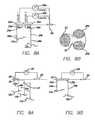
- FIG. 8Ais a schematic view illustrating two channels, using two surface cathodic electrodes, two terminations and a common surface anodic electrode.
- FIG. 8Bis a schematic view illustrating a single patch, two-channels surface electrode.
- FIG. 9Ais a schematic view illustrating several electrical conductors connected to the same termination.
- FIG. 9Bis a schematic view illustrating several electrical conductors connected to terminations which are positioned under a common surface cathodic electrode.
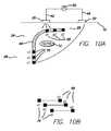
- FIG. 10is a schematic sectional view illustrating a passive electrical conductor implanted subcutaneously, with the conductor having a lead incorporating three conductive stimulating electrodes designated as e 1 , e 2 and e 3 and connected to three conductive pick-up electrodes p 1 , p 2 and p 3 , respectively
- FIG. 11is a schematic sectional view illustrating a passive electrical conductor implanted subcutaneously, and positioning of the surface cathodic electrode over the conductive pick-up electrode p 3 to divert electrical current via the p 3 -e 3 path.
- FIG. 12Ais a schematic sectional view illustrating a passive electrical conductor implanted subcutaneously, and insulation of conductive pick-up electrodes p 1 and p 2 and exposure of conductive pick-up electrode p 3 to divert electrical current to stimulating electrode e 3 .
- FIG. 12Bis a schematic sectional view illustrating a passive electrical conductor implanted subcutaneously, and insulation of conductive pick-up electrode p 1 and exposure of conductive pick-up electrodes p 2 and p 3 to divert electrical current to stimulating electrodes e 2 and e 3 .
- FIG. 12Cis a schematic sectional view illustrating a passive electrical conductor implanted subcutaneously, and insulation of conductive pick-up electrodes p 2 and exposure of conductive pick-up electrodes p 1 and p 3 to divert electrical current to conductive pick-up electrodes e 1 and e 3 .
- FIG. 12Dis a schematic sectional view illustrating a passive electrical conductor implanted subcutaneously, and positioned below both of the surface cathodic and anodic electrodes.
- FIG. 12Eis a schematic sectional view illustrating two passive electrical conductors implanted subcutaneously, with one conductor being positioned below the surface cathodic electrode, and the other conductor being positioned below the surface anodic electrode.
- FIG. 13is a schematic view illustrating wireless selection of conductive pick-up/stimulating electrodes by electronic circuits based on non-volatile memory.
- FIG. 14Ais a schematic sectional view illustrating a passive electrical conductor implanted subcutaneously, and a branched arrangement of the conductive pick-up electrodes.
- FIG. 14Bis a schematic sectional view illustrating the conductive pick-up electrodes of FIG. 14A following trimming.
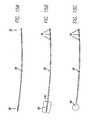
- FIG. 15Ais a schematic view illustrating a lead having a conductive pick-up electrode and three conductive stimulating electrodes.
- FIG. 15Bis a schematic view illustrating a lead having a conductive pick-up coil electrode with insulating backing
- FIG. 15Cis a schematic view illustrating a lead having a conductive pick-up circular electrode and three conductive stimulating electrodes.
- FIG. 15Dis a schematic view illustrating lead having a conductive pick-up circular electrode with insulating backing and three conductive stimulating electrodes.
- FIG. 15Eis a schematic view illustrating a lead having a conductive pick-up electrode to which insulating backing is attached during implantation.
- FIG. 16Ais a schematic plan view illustrating a “paddle type” electrode having a paddle with conductive stimulating electrodes and disc-shaped conductive pick-up electrodes, arranged in a line.
- FIG. 16Bis a schematic plan view illustrating a “paddle type” electrode having a paddle with conductive stimulating electrodes and disc-shaped conductive pick-up electrodes, arranged as a cluster.
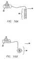
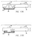
- FIGS. 17A and 17Bare schematic sectional views illustrating a conductive pick-up electrode with insulating material implanted subcutaneously.
- the present inventionbroadly relates to improvements of a “router system” as described in International Publication No. WO 2005/070494 A1 to Prochazka (published Aug. 4, 2005 and claiming priority from U.S. Provisional Patent Application No. 60/538,618 filed Jan. 22, 2004), and U.S. patent application Ser. No. 11/337,824 filed Jan. 23, 2006 to Gaunt and Prochazka.
- These applicationsdescribe an implant for electrically stimulating a target body tissue, such as a nerve, in a subject to either activate or block neural impulses depending on the condition to be treated.
- FIG. 1 taken from WO 2005/070494 A1shows the subject's skin 10 , a nerve 12 , nerve sheath 14 , and a muscle 16 .
- the implant 18provides a conductive pathway for at least a portion of the electrical current flowing between the surface cathodic and anodic electrodes 20 , 22 .
- the implant 18comprises a passive electrical conductor 24 of sufficient length to extend, once implanted, from subcutaneous tissue located below the surface cathodic electrode 20 to the target body tissue 12 .
- the electrical conductorhas a pick-up end 26 and a stimulating end 28 , of which one or both form electrical terminations having sufficient surface areas for reducing the electrical impedance of the interface between the pick-up and stimulating ends 26 , 28 of the electrical conductor 24 and the surrounding body tissues.
- the terminations 30are shown in FIG. 1 in the form of an embracing cuff 32 placed around the nerve 12 .
- An optional electrical return conductor 34provides a low-impedance conductive pathway from the target body tissue to the surface anodic electrode 22 , thereby concentrating the electric field through the target tissue 12 .
- the electrical return conductor 34has a collecting end 36 and a returning end 38 .
- Cathodic wire 42 and anodic wire 44are connected to an external stimulator (not shown) to which operating power is provided by a power source (not shown).
- the implant 18provides a conductive pathway for at least a portion of the electrical current flowing between the surface cathodic and anodic electrodes 20 , 22 .
- the router systemhas been described in International Publication No. WO 2005/070494 A1 and U.S. patent application Ser. No. 11/337,824 as beneficial for various conditions in which stimulation to either activate or block neural impulses is required.
- Such conditionscan include movement disorders (e.g., spasticity, hypertonus, rigidity, tremor and/or muscle weakness, Parkinson's disease, dystonia, cerebral palsy), muscular disorders (e.g., muscular dystrophy), incontinence (e.g., urinary bladder disorders), urinary retention, pain (e.g., migraine headaches, neck and back pain, pain resulting from other medical conditions), epilepsy (e.g., generalized and partial seizure disorder), cerebrovascular disorders (e.g., strokes, aneurysms), sleep disorders (e.g., sleep apnea), autonomic disorders (e.g., gastrointestinal disorders, cardiovascular disorders), disorders of vision, hearing and balance, and neuropsychiatric disorders (e.g.,
- the present inventioncontemplates use of the router system for specific categories of conditions described in Table 1:
- the external stimulus generatordelivers the required stimulation (for example, symmetric or asymmetric stimulation, 30 pulses per second, 200 ⁇ sec pulse width) upon triggering by a Foot Sensor, indicating heel on/heel off events.
- the termination (stimulating electrode)is positioned near the Prevention) appropriate motor point.
- the stimulating electrodemay be positioned near the axillary nerve.
- the pick-up endis positioned below the skin in the shoulder area.
- the external stimulatoris activated for a specific time, for example 1 hour, with symmetric or asymmetric stimulation, 30 pulses per second, 200 ⁇ sec pulse width, 5 sec ON and 5 sec OFF time.
- Pain treatmentcan be delivered in several ways, namely by stimulating subcutaneously, stimulating peripheral nerves, or stimulating nerve roots, for example in the epidural space. Pain treatment stimulation usually requires higher frequencies (more pulses per second) as compared to the motor point stimulation—usually within the range of 30-50 pulses per second.
- the termination (stimulating end)is positioned in the appropriate area, and the pick-up end is positioned subcutaneously in a convenient space. An optimal location is one that does not cause the lead to cross the joints, or the pick-up end to be positioned in the moving area. The stimulation is initiated or stopped by the patient.
- the router systemis applied in a similar manner as described for the orthopedic recovery applications.
- Head and neck Cluster headachesdental disorders, migraine headaches, spondylosis, pain sprains, strains, suboccipital headaches, TMJ disorders, torticollis, whiplash, thoracic outlet syndrome.
- the router systemis applied in a similar manner as described for the orthopedic recovery applications.
- the router systemis applied in a similar manner as described for the orthopedic recovery applications.
- Back pain Facet syndromeintercostal neuralgia, sacroiliac joint dysfunction, lumbago, lumbosacral pain, radiculitis, IVD syndrome, degenerative disc disease, spinal stenosis, sprains, strains, throacodynia, whole back pain.
- the router systemis applied in a similar manner as described for the orthopedic recovery applications.
- the router systemis applied in a similar manner as described for the orthopedic recovery applications.
- the categories of conditions in Table 1broadly relate to muscle stimulation (e.g., functional/rehabilitation stimulation, prevention of pain or spasticity, orthopedic recovery); pain treatment; and cosmetic applications.
- Functional/rehabilitation stimulationattempts to restore normal activity by activating selected muscles.
- Functional/rehabilitation stimulationcan be continuous (e.g., as applied to urge incontinence) or repeatable (e.g., as applied to diaphragm-pacing, arm rehabilitation and gait control).
- Prevention of pain or spasticityincludes stimulation applications for preventing pain, rather than suppressing pain.
- Orthopedic recoveryincludes muscle stimulation to prevent atrophy or prevention of post-procedure pain as associated with knee replacement. The same areas of the body may be stimulated; for example, radiculitis and lower back pain may overlap and have the same stimulation sites.
- Cosmetic applicationsinclude electrical stimulation targeted at cosmetic improvements, for example, electrical stimulation to help build and maintain muscles in peak condition (e.g., when normal exercise is suspended due to injury), maintain peripheral circulation, relax muscles following strain, or firm abdominal muscles following
- the present inventioncontemplates that the router system can be used to deliver electrical current to either external or implanted devices, to multiple target body tissues and to selective target body tissues as described below.
- the router systemcan be used to deliver electrical energy to one or more electrical devices which are powered by electrical current or which process electrical signals.
- electrical devicesmay include, for example, sensors (for example, ENG sensors, temperature sensors, pressure sensors, pH sensors, impedance sensors, and others known to one skilled in the art), amplifiers, filters, high voltage/constant current generators, switches, power supplies, batteries, battery-charging circuits, miniature rechargeable batteries, processors, frequency shifters, over-stimulation protection circuit, communication modules (wired or wireless) and other suitable devices known to those skilled in the art.
- Such electrical devicescan be either external to the body or implanted within the body.
- Implanted electrical devicesare preferably biocompatible and non-toxic, or enclosed in a biocompatible case, generating no significant undesirable host response for the intended utility.
- biocompatible sensors for assessing intra-body parameters and pre-processing circuits, communication circuits and power supply circuitsare typically implanted within the body, such that raw data from implanted electrical devices, for example sensors, are transmitted to devices external to the body, for example, post-processing circuits which involve sophisticated algorithms, and greater processing power, space and power requirements compared to implanted devices.
- the router systemcan be used to deliver electrical signals (monopolar and bi-polar signals) from target tissues within the body (electroneurographic or ENG signals) to external electrical devices.
- ENGis a common non-invasive test for examining the integrity of target tissues or organs by recording the spontaneous electrical activity of target tissues or organs, or by assessing the response of electrically excitable tissues or organs to stimulation.
- the Auditory Brainstem Response (ABR) testprovides objective information about the upper auditory system including the inner ear and brainstem.
- the target tissueis typically a nerve, for example a peripheral nerve, or organ for example a particular muscle innervated by a nerve.
- FIG. 2illustrates use of the router system for acquiring ENG signals.
- Two surface electrodesfor example, two surface cathodic electrodes 20 a and 20 b ) are shown positioned separately over two implanted passive electrical conductors 24 a and 24 b .
- Electrical conductor 24 ais focused in proximity to first point of the nerve 12
- electrical conductor 24 bis in proximity to a second point of the same nerve 12 .
- One surface reference electrode(for example, surface anodic electrode 22 ) is positioned on the skin 10 .
- Electrical conductors 24 a and 24 bdeliver the electrical signal from the first and second points of the nerve 12 , respectively.
- a differential amplifier 46is provided to amplify the difference between the ENG signals at each of the first and second points of the nerve 12 . Measurement of the amplified electrical signal is subsequently performed for example, by an RMS meter, peak meter, or oscilloscope, or digital data acquisition system.
- Differential amplifier 46 aamplifies the signal at the first point (ENG 1 )
- differential amplifier 46 bamplifies the signal at the second point (ENG 2 ).
- the ENG signalcan be amplified by a differential amplifier connected between an electrical conductor 24 and a surface reference electrode (for example, surface anodic electrode 22 ).
- the signal-to-noise ratio of the ENG signalcan be improved by implanting an amplifier.
- the amplifieris implanted and connected between the conductors 24 a and 24 b .
- the amplifieramplifies the ENG signal and delivers the amplified signal via the electrical conductor 24 and termination 30 to an external signal acquisition device which is connected between the external surface electrodes 20 a and 20 b .
- the implanted amplifier and additional electronic circuits(for example, a series of amplifiers; a band pass filter to limit the bandwidth to only the signals of interest; or a band stop filter to prevent entry of 50 Hz or 60 Hz induced by the power lines) can be powered by an external generator delivering sub-threshold current through the skin 10 .
- Various conditionsrequire use of the router system as described above to deliver electrical signals from target tissues within the body; for example, monitoring of gastric activity. Deviations in the electrical pattern of gastric activity can be indicative of different pathological conditions, for example, delayed gastric emptying time.
- the prior art approachis to record electrical activity by external electrodes, which have the disadvantage of being exposed to electrical noise and electrical signals from non-targeted organs.
- the present applicationcontemplates that the router system as useful in the stomach area to improve the ability to monitor these signals.
- the router systemcan be also used to deliver electrical current to one or more implanted electrical devices 48 .
- the implanted passive electrical conductor 24has a pick-up end 26 and a delivery end 28 (rather than a stimulating end 28 per se).
- the pick-up end 26allows a sufficient portion of electrical current to flow through the electrical conductor 24 .
- the delivery end 28delivers electrical current to one or more electrical devices 48 .
- the present inventioncontemplates that the router system can be used for dual purposes, namely to deliver electrical current to one or more implanted devices 48 , and to stimulate a target body tissue.
- the implanted passive electrical conductor 24has one end which is a pick-up end 26 and another end which acts as both a delivery end 28 to deliver electrical current to one or more implanted electrical devices 48 , and a stimulating end 28 to deliver electrical current to a target body tissue.
- the electrical conductor 24is schematically shown in FIGS. 3 , 4 , 5 and 6 as being positioned under the surface cathodic electrode 20 ; however, it will be appreciated by those skilled in the art that the electrical conductor 24 can be positioned below either or both of the surface cathodic electrode 20 or the surface anodic electrode 22 .
- Implanted electrical devices 48can be positioned anywhere along the electrical conductor 24 or can be formed as part of the termination 30 for example, of the pick-up end 26 .
- FIG. 3illustrates several approaches as examples for incorporating implanted electrical devices 48 with the router system.
- An external stimulator 50delivers sub-threshold (or above threshold) transcutaneous electrical current picked up by a termination 30 a , 30 b , 30 c .
- Implanted devices 48can be built as part of the termination 30 a (for example, device 48 a ); as separate but adjacent to the termination 30 b (for example, device 48 b ); or as separate and remote relative to the termination 30 c (e.g., implanted near the nerve as for example, device 48 c ).
- the implanted electrical device 48can be connected in series, as illustrated by the positioning of device 48 a .
- the external stimulator 50provides electrical current to the surface cathodic electrode 20 which is delivered to termination 30 a .
- the electrical current picked up by termination 30 a(designated as “It”) then flows through device 48 a , continues through the electrical conductor 24 a and the stimulating end 28 a to be delivered into the target body tissue, for example nerve 12 .
- the electrical currentreturns through the body tissue and the surface anodic electrode 22 to the external stimulator 50 .
- a “parallel” connectionas illustrated by the positioning of device 48 b , can be used.
- the device 48 bconsumes a portion (designated as “le”) of the “It” electrical current picked up by the termination 30 b .
- the return currentis shown flowing from device 48 b through body tissue to the surface anodic electrode 22 .
- the electrical current(designated as “Is” which is It-le) flows via the electrical conductor 24 b to the stimulating end 28 b and returns to the surface anodic electrode 22 through body tissue.
- Implanted amplifierscan improve the quality of the acquisition of the intra-body electrical signals.
- Electrical currentis delivered to power the amplifier.
- the required currentcan be, for example, less than 1 mA, and at a frequency of higher than 50 KHz in order to pass easily through the skin, to avoid sensation or stimulation, or to avoid interference with the measured ENG signal.
- FIG. 5illustrates the use of the router system to deliver electrical energy to implanted devices for acquiring ENG signals from a target tissue, for example a nerve 12 .
- the implanted devices shown generally at 48include a power supply 52 , a differential amplifier 46 , a frequency shifter 54 and a reference electrode 56 .
- the reference electrode 56serves to measure the difference of potentials between it and the nerve 12 , as picked by the stimulating end 28 and a reference electrode located elsewhere in the tissue.
- the reference electrode 56can be positioned within the distance of several millimeters to several centimeters of the stimulating end 28 .
- the external stimulator 50delivers a sub-threshold signal, which can be, for example, a sinusoidal signal having a frequency outside those of the ENG, to the surface cathodic electrode 20 which delivers the electrical current to termination 30 .
- the electrical current, picked up by termination 30is then rectified and stabilized by the power supply 52 .
- the external stimulator 50is used to deliver a symmetrical waveform of high frequency, for example, usually higher than 30-50 KHz.
- DC currentis required.
- Power supply 52rectifies the current delivered by the stimulator 50 to pick-up electrode 30 , and than stabilizes it and creates the required voltages/currents.
- the power supply 52in turn delivers power to the differential amplifier 46 .
- the differential amplifier 46amplifies the nerve signal 12 picked up by the stimulating end 28 .
- the amplified signalis then fed back to the termination 30 to the external cathodic electrode.
- the currentflows from the external stimulator 50 to the surface cathodic electrode 20 , via capacitive coupling to termination 30 , via power supply 52 to electronic circuits, e.g. amplifier 46 , continues to the electrical conductor 24 , stimulating end 28 , and returns through the tissue to the surface anodic electrode 22 , to the external stimulator 50 .
- electronic circuitse.g. amplifier 46
- the signals generated by the amplifier 46 and the frequency shifter 54can be superimposed on the same current path. These signals do not interfere with the measurements, since a frequency shifter 54 can be optionally provided to shift the amplified ENG signal outside the frequency spectrum of the original ENG signal, thereby preventing interference with the original ENG signal.
- amplitude modulationwhere the signal is mixed with a carrier wave, resulting in shifting the original signal spectrum to be around the carrier frequency
- SSBsingle side band modulation
- FMfrequency modulation
- PMphase modulation
- the signalcan be transmitted in its analog form or using digital encoding.
- the amplified signalcan be processed by using analog or digital processing techniques; for example, the amplified signal can be filtered by an external filter 58 , shifted back to the original frequency, and output for the further processing.
- time divisioncould be used.
- the ENG signalis amplified and recorded in the implanted module or recording device, and in the next time slot, the recorded signal is transmitted through the termination 30 .
- Wireless transmission of the informationalso can be applicable.
- FIG. 6illustrates use of the router system to deliver electrical energy to an over-stimulation protection circuit shown generally at 60 .
- a controller 62 and a power supply 52are implanted in connection with the passive electrical conductor 24 .
- the controller 62includes a switch 64 for selectively disconnecting the stimulating end 28 .
- the disconnectioncan be performed, for example, if the electrical current exceeds a pre-defined threshold.
- an external devicecan be used to provide a signal to connect or disconnect the stimulating end 28 .
- the power supply 52can incorporate a non-volatile memory to store a serial number or code number of an external stimulator 50 .
- the external stimulator 50transmits a number and, if the number matches the stored number, the stimulating end 28 is then connected; otherwise, the stimulating end 28 is disconnected. This approach prevents use of unauthorized or unapproved external stimulators.
- the router systemcan be used to deliver electrical energy to charge implanted batteries.
- miniature implantable stimulatorscan be charged using this approach.
- FIG. 7One of the possibilities for transmitting both stimulus and data is shown in FIG. 7 .
- One possible approachis to transmit the data between the successive stimuli.
- the datais transmitted, for example, by modulating a sub-threshold sine wave. Amplitude modulation is shown in the example; however, various other modulation techniques alternatively could be used.
- the electrical conductor 24is schematically shown in FIGS. 8A , 9 A and 9 B as being positioned under the surface cathodic electrode 20 ; however, it will be appreciated by those skilled in the art that the electrical conductor 24 can be positioned below either or both of the surface cathodic electrode 20 or the surface anodic electrode 22 .
- each surface cathodic electrode 20 a , 20 bis positioned over a separate implanted passive electrical conductor 24 a , 24 b which extends to a different target body tissue 12 a , 12 b .
- Each electrical conductor 24 a , 24 bforms an electrical termination 30 a , 30 b at its pick-up end 26 a , 26 b , and provides a conductive pathway for at least a portion of the electrical current flowing between the plurality of surface cathodic electrodes 20 a , 20 b and the one anodic electrode 22 .
- Each surface cathodic electrode 20 a , 20 bcan be connected either to separate stimulators 50 a , 50 b (Le., creating two separate channels as shown in FIG. 8A ) or to a single multi-channel stimulator 50 (for example, a single patch, two-channels surface electrode arranged on conductive material 65 as shown in FIG. 8B ).
- the surface anodic electrode 22can be connected to each of the separate stimulators 50 a , 50 b or to the single multi-channel stimulator 50 .
- the surface cathodic electrode 20is positioned over one termination 30 to which more than one separate implanted passive electrical conductors 24 a , 24 b , 24 c are connected by any suitable means, for example, a crimp connection 67 or by welding ( FIG. 9A ).
- the surface cathodic electrode 20can be positioned over more than one separate termination 30 a , 30 b in order to provide electrical current to more than one electrical conductor 24 a , 24 b ( FIG. 9B ).
- the surface cathodic electrode 20can be divided into segments, with each segment being connected individually to an external stimulator 50 by a switching matrix.
- the switchesare operated either manually or by a controller. Electrical stimulation is thereby delivered mainly to the area of the surface cathodic electrode 20 which is positioned above the termination 30 of the electrical conductor 24 .
- appropriate algorithmscan be determined to deliver optimal stimulation; for example, by choosing the segment having the lowest impedance. This arrangement provides easier alignment with the electrical conductor 24 ; a smaller skin surface 10 conducting the electrical current; and a way of balancing stimulation when a plurality of electrical conductors 24 are present.
- a solutionis to implant the termination 30 in an accessible place, and to tunnel a lead to the target body tissue.
- the stimulation sitecan be either focused (i.e., adjacent the target body tissue) or dispersed (i.e., not adjacent to any specific target body tissue).
- the above arrangementsrequire one or more external stimulators 50 for supplying electrical current to the surface cathodic and anodic electrodes 20 , 22 .
- Suitable external stimulators 50include an external stimulator 50 connected to electrodes 20 , 22 , a portable stimulator 50 attached to electrodes 20 , 22 and including a power source, or a portable stimulator 50 controlled by a remote control.
- the external stimulator 50can be simply connected by the cathodic and anodic wires 42 , 44 to the surface cathodic and anodic electrodes 20 , 22 placed on the skin 10 (as shown in FIG. 1 ).
- attachment of the electrodes 20 , 22might be challenging, requiring individual placement of the electrode 20 , 22 and individual connection of the electrode 20 , 22 to the stimulator 50 .
- the inconveniencemay be extreme on unreachable body parts, e.g., on the shoulder.
- the size of the stimulator 50might limit mobility of the subject. While acceptable for applications requiring limited duration of stimulation, it might be limiting for other applications.
- a portable stimulator 50which includes cathodic and anodic electrodes 20 , 22 and display and control buttons can be used.
- access to the stimulator's control and display buttonsmight be inconvenient and/or limited. For example, placement on the shoulder will prevent access to such display and control buttons.
- the portable stimulator 50includes, but is not limited to, multiple-use electrodes, a limited user interface (on/off LED) and remote control unit with display and control functions.
- this set-uprequires an additional device in the form of the remote control, and additional regulatory aspects (for example, FCC, European Radio regulations).
- a single remote unitcan be used to control several stimulators 50 which might require more complicated communication protocol and unique ID for each stimulator 50 in order to prevent collision between different users.
- the difficulty of positioning surface cathodic and anodic electrodes 20 , 22 , for example on the shoulder,can be overcome by using a flexible garment or a rigid orthosis.
- Non-limiting examplesinclude the T-CUFFTM (A. Prochazka, University of Alberta) comprising a glove in which the stimulator is embedded, and the NESS H200TM (NESS Ltd., Israel) comprising a rigid orthosis having embedded electrodes and a stimulator connected by a wire.
- the pick-up electrodes 20 for activating flexors and extensorscan be positioned under the skin 10 in the forearm. The activation may be achieved, for example, by applying pulses of 200 ⁇ sec duration, 30 pulses per second, for several seconds, alternating between flexors and extensors.
- the router systemcan be used to stimulate multiple target body tissues as discussed above, greater stimulation of particular body tissues over others may be needed. For example, in subcutaneous stimulation for pain treatment, it may be required to stimulate the entire area of pain.
- the present inventionfurther contemplates that the router system can be used to deliver electrical current selectively.
- the passive electrical conductor 24can be formed from a lead 66 having a pick-up end 26 and a stimulating end 28 (for example, as shown in FIG. 10 ).
- the pick-up end 26can comprise one or more conductive pick-up electrodes 68
- the stimulating end 28can comprise one or more conductive stimulating electrodes 70 .
- the conductive stimulating electrode 70 on the lead 66usually has a optimal size. If the conductive stimulating electrode 70 is too small, for example, having surface of less than 10 mm 2 , the transfer impedance between the conductive stimulating electrode 70 and the target body tissue 12 will be too high.
- the conductive stimulating electrode 70is too large, for example, greater than 50-60 mm 2 , the current density delivered by the conductive stimulating electrode 70 will be too low to activate target body tissue, for example the nerve 12 .
- the optimal length of the conductive stimulating electrode 70is usually of several millimeters, preferably 3-4 mm, having an area of about 20 mm 2 . It is generally positioned in the vicinity of the targeted nerve, preferably 1-3 mm, more preferably 1 mm or less. Due to constraints of implantation and concern of mechanical nerve damage, the conductive stimulating electrode 70 is generally not placed touching the nerve; otherwise, the required stimulation levels will be too high, causing undesirable sensations and/or local muscle contractions.
- a solutionis to implant an array of electrodes 68 , 70 and to activate the electrodes 68 , 70 in the desired locations, or to implant a combination of electrodes 68 , 70 resulting in an optimal delivery of stimulation, known as “current steering.”
- the ability to select different pick up or stimulating electrodes 68 , 70 during or after implantation of the lead 66can be beneficial; for example, if the stimulating end 28 or the target tissue have migrated within the body and the selected stimulating electrode 70 is no longer in the vicinity of the target body tissue; or if any wires between the pick-up electrode 68 and the stimulating electrode 70 become damaged.
- FIG. 10shows an implanted passive electrical conductor 24 comprising a lead 66 incorporating three conductive stimulating electrodes 70 designated as e 1 , e 2 and e 3 and three conductive pick-up electrodes 68 designated as p 1 , p 2 and p 3 , respectively.
- FIG. 10 (panel B)shows that each conductive pick-up electrode 68 has a corresponding conductive stimulating electrode 70 .
- each conductive pick-up electrode 68can have more than one corresponding conductive stimulating electrode 70 .
- Conductive stimulating electrode e 3is positioned closest to the target body tissue (i.e., nerve 12 ).
- a surface cathodic electrode 20is positioned on the skin 10 above the conductive pick-up electrode “p 1 .”
- the electrical current provided to the surface cathodic electrode 20flows through “p 1 ” and “e 1 ” to the surface anodic electrode 22 (e 1 is the corresponding conductive stimulating electrode for conductive pick-up electrode p 1 ).
- Most of the electrical currentis thus not delivered to the nerve 12 .
- positioning the surface cathodic electrode 20 over the conductive pick-up electrode p 3diverts the current via the p 3 -e 3 path, resulting in the electrical current passing in the vicinity of the nerve 12 to provide stimulation (e 3 is the corresponding conductive stimulating electrode for conductive pick-up electrode p 3 ).
- the surface cathodic electrode 20can be sized to overlap one or more conductive pick-up electrodes 68 , although delivery of the electrical current might be less focused. Further, one or more conductive pick-up electrodes 68 can be exposed, while the remaining conductive pick-up electrodes 68 are insulated with a layer of single use or removable and re-attachable electrical insulation. The insulation layer can be scratched, cut or dissolved during the fitting process (i.e., testing which conductive pick-up and stimulating electrodes 68 , 70 are the most efficient to deliver stimulation to the target body tissue).
- the insulation layercan be removed and re-attached to the conductive pick-up electrode 68 by suitable means, for example a sleeve which is either slidable over the conductive pick-up electrode 68 to provide insulation preventing the flow of electrical current, or removable and re-attachable to expose the conductive pick-up electrode 68 , thereby receiving the flow of electrical current.
- suitable meansfor example a sleeve which is either slidable over the conductive pick-up electrode 68 to provide insulation preventing the flow of electrical current, or removable and re-attachable to expose the conductive pick-up electrode 68 , thereby receiving the flow of electrical current.
- FIG. 12Aillustrates conductive pick-up electrodes p 1 and p 2 which are insulated and conductive pick-up electrode p 3 which is exposed. The electrical current is subsequently diverted to the conductive stimulating electrode e 3 positioned in the vicinity of the nerve 12 (e 3 is the corresponding conductive stimulating electrode for conductive pick-up electrode p 3 ).
- FIG. 12Billustrates the nerve 12 positioned between conductive stimulating electrodes e 2 and e 3 . Insulation of conductive pick-up electrode p 1 and exposure of conductive pick-up electrodes p 2 and p 3 diverts electrical current to conductive stimulating electrodes e 2 and e 3 , thereby stimulating the nerve 12 .
- FIG. 12Cillustrates two nerves 12 a , 12 b , with conductive stimulating electrode e 3 positioned at one nerve 12 a and conductive stimulating electrode e 1 positioned at the other nerve 12 b .
- Conductive pick-up end p 2is insulated, while conductive pick-up electrodes p 1 and p 3 are exposed. Electrical current is diverted to conductive pick-up electrodes p 1 and p 3 , which deliver the electrical current to conductive pick-up electrodes e 1 and e 3 respectively, to stimulate the nerves 12 a , 12 b.
- FIGS. 10 , 11 , 12 A, 12 B and 12 Cillustrate the electrical conductor 24 as being positioned under the surface cathodic electrode 20 ; however, it will be appreciated by those skilled in the art that the electrical conductor 24 can be positioned below either or both of the surface cathodic electrode 20 or the surface anodic electrode 22 .
- FIG. 12Dillustrates an implanted passive electrical conductor 24 having a lead 66 incorporating three conductive pick-up electrodes 68 designated as p 1 , p 2 and p 3 and three conductive stimulating electrodes 70 designated as e 1 , e 2 and e 3 , respectively.
- the conductive pick-up electrodes 68 of the lead 66are positioned below both the surface cathodic and anodic electrodes 20 , 22
- Conductive pick-up electrode p 1is positioned below the surface cathodic electrode 20
- conductive pick-up electrode p 3is positioned below the surface anodic electrode 22 (e 1 is the corresponding conductive stimulating electrode for conductive pick-up electrode p 1 , while e 3 is the corresponding conductive stimulating electrode for conductive pick-up electrode p 3 ).
- FIG. 12Eillustrates two implanted passive electrical conductors 24 a , 24 b .
- Electrical conductor 24 ahas a lead 66 a incorporating three conductive pick-up electrodes 68 a designated as p 1 , p 2 and p 3 , and three conductive stimulating electrodes 70 a designated as e 1 , e 2 and e 3 , respectively.
- Electrical conductor 24 ais positioned below the surface cathodic electrode 20 , with conductive pick-up electrode p 3 located below surface cathodic electrode 20 (e 3 is the corresponding conductive stimulating electrode for conductive pick-up electrode p 3 ).
- Electrical conductor 24 bhas a lead 66 b incorporating two conductive pick-up electrodes 68 b designated as p 4 and p 5 , and two conductive stimulating electrodes 70 b designated as e 4 and e 5 , respectively. Electrical conductor 24 b is positioned below the surface anodic electrode 22 , with conductive pick-up electrode p 4 located below the surface anodic electrode 22 (e 4 is the corresponding conductive stimulating electrode for conductive pick-up electrode p 4 ).
- wireless or wired selection of conductive pick-up and stimulating electrodes 68 , 70can be achieved by including, for example, electronic circuits based on non-volatile memory 72 ( FIG. 13 ).
- the electrical currentis picked by the conductive pick-up electrodes (p 1 , p 2 , p 3 , p 4 ) and passes through an implanted power supply 52 to operate the non-volatile memory 72 .
- Outputs of the non-volatile memory 72drive switches (T 1 , T 2 , T 3 , T 4 ) which enable or disable the path of electrical current between the conductive pick-up electrodes (p 1 , p 2 , p 3 , p 4 ) and the conductive stimulating electrodes (e 1 , e 2 , e 3 , e 4 ).
- a pre-defined pattern picked by the conductive pick-up electrodes 68activates a programming circuit 74 to change the non-volatile memory 72 so that different patterns of the conductive stimulating electrodes 70 can be selected.
- SMAshape memory alloy
- SMAis a metal which remembers its geometry. After a sample of SMA has been deformed from its original conformation, it regains its original geometry by itself during heating when exposed to a temperature above a particular threshold. By heating the SMA contact, it changes its shape and disconnects the stimulating electrode. For example, SMA changes its shape when heated to 5° C. above the body temperature, and it will maintain this new shape unless it will be cooled 5° C. below the body temperature.
- Transcutaneous heatingperformed for example, by an ultrasonic beam, can operate the SMA based switch from ON to OFF.
- SMAinclude copper-zinc-aluminum, copper-aluminum-nickel, and nickel-titanium alloys.
- Testing of conductive pick-up and stimulating electrodes 68 , 70can be conducted, for example during implantation. Following implantation of the conductive stimulating electrodes 70 at the target body tissue, the conductive pick-up electrodes 68 still protrude percutaneously.
- the conductive pick-up electrodes 68can be connected directly to the external stimulator 50 , and the best conductive pick-up electrode 68 may be chosen.
- the external stimulator 50is connected (e.g. with a clamp) to a certain conductive pick-up electrode or a combination of electrodes.
- the responseis observed. For example, in the case of motor point stimulation, the combination which causes the lowest activation threshold may be selected.
- the patient responseis examined. If the stimulation causes a tingling sensation and the pain disappears, it is an indication of successful combination of the electrodes.
- pick-up electrodes 68One method of selecting pick-up electrodes 68 is to position the surface electrode (for example, surface cathodic electrode 20 ) over a particular implanted pick-up electrode (for example, pick-up electrode p 3 as shown in FIG. 14A ). Alternatively, electrodes which are not used may be trimmed during the implantation and fitting procedure ( FIG. 14B ).
- FIGS. 15A-15ENon-limiting examples of leads 66 useful for the described “current steering” and other applications described herein are illustrated in FIGS. 15A-15E .
- FIG. 15Ashows a lead 66 having a conductive pick-up electrode 68 and three conductive stimulating electrodes 70 .
- Insulating backing 76can be attached to the conductive pick up electrode 68 to increase efficacy of the pick-up end 26 .
- Suitable insulating backing 76can include, for example, silicone, polyester fiber such as DacronTM (lnvista, Inc) or other appropriate biocompatible materials.
- FIG. 15Billustrates a lead 66 having a conductive pick-up coil electrode 68 with insulating backing 76 .
- FIG. 15Cshows a lead 66 having a conductive pick-up circular electrode 68 and three conductive stimulating electrodes 70
- FIG. 15Dshows a conductive pick-up circular electrode 68 with insulating backing 76 and three conductive stimulating electrodes 70
- FIG. 15Eshows a lead 66 having a conductive pick-up electrode 68 to which also insulating backing 76 can be attached, for example, during implantation.
- a further non-limiting example of a lead 66is a double helix lead enclosed in a sheath.
- the construction of the double helix, the anchor and other partsis similar to the lead described by Memberg et al. (1994).
- Memberg et al. (1994)describe a lead including a double helix enclosed in a sheath. The double helix is separated and the non-insulated wires are wound back on the stimulating end to which an anchor is attached.
- an electrode without an anchormay serve as a single pick-up end electrode.
- the lead of Memberg et al. (1994)has been modified.
- the double helixis separated and the wires wound back, forming two separate conductive pick-up electrodes 68 .
- the double helixis separated and the wires are wound back, forming two separate conductive stimulating electrodes 70 .
- the double helixis separated and the wires are wound back separately to form two separate conductive pick-up electrodes 68 and two separate conductive stimulating electrodes 70 .
- anchor-shaped tinescan be formed at the stimulating end 28 to anchor the conductive stimulating electrodes 70 in position.
- multiple electrodes leads 66can be connected via matching connectors to the array of conductive pick-up electrodes 68 .
- Non-limiting examplesinclude Axxess 3/6 lead (Advanced Neuromodulation Systems Inc., USA) or TO type lead (Dr. Osypka, GmbH Medizintechnik, Germany).
- FIGS. 16A and 16Bshow a “paddle type” electrode 78 incorporating both conductive pick-up and stimulating electrodes 68 , 70 .
- FIG. 16Aillustrates a “paddle type” electrode 78 having a paddle 80 with conductive stimulating electrodes 70 , and disc-shaped conductive pick-up electrodes 68 arranged in a line.
- FIG. 16Billustrates a “paddle type” electrode 78 having disc-shaped conductive pick up electrodes 68 arranged as a cluster.
- the advantages of specific arrangementdepends on the size and the shape of the area that should be covered by the electrodes.
- a conductive pick-up electrode 68 with insulating material 82 covering its surface and peripheryis beneficial. Electrical current from the surface cathodic electrode 20 may “escape” (escaping current designated as “lescape”) from the periphery of the conductive pick-up electrode 68 into the tissue ( FIG. 17A ). The path of this electrical current through the skin 10 may be short (indicated as “d”); thus, the resistance of the path may be small. It is known that the larger the diameter of the conductive pick-up electrode 68 , the larger the peripheral area. This phenomenon acts against and may neutralize improved transcutaneous delivery for the larger diameter of the conductive pick-up electrode 68 .
- insulating material 82is can be applied to cover the periphery of the conductive pick-up electrode 68 to cover the distance similar to the thickness of the skin 10 ( FIG. 17B ).
- insulating material 82can be positioned below and extended beyond the conductive pick-up electrode 68 .
- Suitable insulating material 82can include, for example, silicone, polyester fiber such as DacronTM (Invista, Inc) or other appropriate biocompatible materials.
- the surface cathodic electrode 20is preferably at least 10 mm in diameter.
- the conductive pick-up electrode 68is preferably at least 16 mm in diameter.
- the conductive pick-up electrode 68is covered with for example, at least 3 mm of insulating material 82 on its periphery.
Landscapes
- Health & Medical Sciences (AREA)
- Life Sciences & Earth Sciences (AREA)
- Veterinary Medicine (AREA)
- Animal Behavior & Ethology (AREA)
- Public Health (AREA)
- Engineering & Computer Science (AREA)
- Biomedical Technology (AREA)
- Nuclear Medicine, Radiotherapy & Molecular Imaging (AREA)
- Radiology & Medical Imaging (AREA)
- General Health & Medical Sciences (AREA)
- Heart & Thoracic Surgery (AREA)
- Biophysics (AREA)
- Pain & Pain Management (AREA)
- Neurology (AREA)
- Neurosurgery (AREA)
- Cardiology (AREA)
- Electrotherapy Devices (AREA)
Abstract
Description
- a passive electrical conductor of sufficient length to extend, once implanted, from subcutaneous tissue located below either or both of the surface cathodic electrode or the surface anodic electrode to the target body tissue,
- the electrical conductor having a pick-up end and a stimulating end, and being insulated between its ends, the pick-up end having a plurality of conductive pick up electrodes and the stimulating end having a plurality of conductive stimulating electrodes, and each of the conductive pick-up electrodes being electrically connected with one or more corresponding conductive stimulating electrodes, such that positioning of either or both of the surface cathodic electrode or the surface anodic electrode over one of the conductive pick-up electrodes causes the portion of the electrical current to be transmitted to the one or more corresponding conductive stimulating electrodes electrically connected to the one of the conductive pick-up electrodes;
- a passive electrical conductor of sufficient length to extend, once implanted, from subcutaneous tissue located below either or both of the surface cathodic electrode or the surface anodic electrode to the target body tissue, and
- the electrical conductor having a pick-up end and a stimulating end, and being insulated between its ends, the pick-up end having a plurality of conductive pick-up electrodes and the stimulating end having a plurality of conductive stimulating electrodes, and each of the conductive pick-up electrodes being electrically connected with one or more corresponding conductive stimulating electrodes, such that positioning of either or both of the surface cathodic electrode or the surface anodic electrode over one of the conductive pick-up electrodes causes the portion of the electrical current to be transmitted to the one or more corresponding conductive stimulating electrodes electrically connected with that one of the conductive pick-up electrodes.
- a passive electrical conductor of sufficient length to extend, once implanted, from the subcutaneous tissue located below either or both of the surface cathodic electrode or the surface anodic electrode to the one or more electrical devices,
- the electrical conductor having a pick-up end and a delivery end and being insulated between its ends, the pick-up end forming an electrical termination having a sufficient surface area to allow a sufficient portion of the electrical current to flow through the conductor, and the delivery end forming an electrical termination for delivering the portion of electrical current to the one or more electrical devices;
- a passive electrical conductor of sufficient length to extend, once implanted, from subcutaneous tissue located below either or both of the surface cathodic electrode or the surface anodic electrode to the one or more electrical devices,
- the electrical conductor having a pick-up end and a delivery end and being insulated between its ends, the pick-up end forming an electrical termination having a sufficient surface area to allow a sufficient portion of the electrical current being applied to flow through the conductor, in preference to current flowing through body tissue between the surface cathodic and anodic electrodes, such that the one or more devices are supplied with current, and the delivery end forming an electrical termination with the one or more devices for delivering the portion of electrical current to the one or more devices; and
- a passive electrical conductor of sufficient length to extend, once implanted, from subcutaneous tissue located below a surface electrode positioned on the subject's skin to the target body tissue,
- the electrical conductor having a pick-up end and a delivery end and being insulated between its ends, the pick-up end forming an electrical termination having a sufficient surface area to allow the electrical signal from the target body tissue to flow through the conductor, and the delivery end forming an electrical termination for delivering the electrical signal to the one or more external devices;
- a passive electrical conductor of sufficient length to extend, once implanted, from subcutaneous tissue located below the at least one surface electrode to the target body tissue,
- the electrical conductor having a pick-up end and a delivery end and being insulated between its ends, the pick-up end forming an electrical termination having a sufficient surface area to allow the electrical signal from the target body tissue to flow through the conductor, and the delivery end forming an electrical termination for delivering the electrical signal to the one or more external devices.
- a passive electrical conductor of sufficient length to extend, once implanted, from subcutaneous tissue located below either the one or more surface cathodic electrodes or the one or more surface anodic electrodes to a plurality of target body tissues, and
- each electrical conductor having a pick-up end and a stimulating end and being insulated between its ends, the pick-up end forming an electrical termination having a sufficient surface area to allow a sufficient portion of the electrical current to flow through the conductor such that the target body tissue is stimulated, and the stimulating end forming an electrical termination for delivering the portion of electrical current to the target body tissue;
- a passive electrical conductor of sufficient length to extend, once implanted, from subcutaneous tissue located below either the surface cathodic electrode or the surface anodic electrode to the target body tissue,
- the electrical conductor having a pick-up end and a stimulating end and being insulated between its ends, the pick-up end forming an electrical termination having a sufficient surface area to allow a sufficient portion of the electrical current being applied to flow through the conductor, in preference to current flowing through body tissue between the surface cathodic and anodic electrodes, such that the target body tissue is stimulated, and the stimulating end forming an electrical termination for delivering the portion of electrical current to the target body tissue.
| TABLE 1 |
| Summary of Conditions |
| Category of | |
| Condition | Examples of Specific Conditions |
| Functional/ | Hand rehabilitation, gait control, transfers and standing, FES-induced |
| Rehabilitation | bicycling, arm cranking, FES systems for grasping and reaching, |
| ejaculation, erectile dysfunction, dysphagia, cervical dystonia, | |
| diaphragm pacing, fecal incontinence, cough assistance, improvement | |
| of circulation, prevention and treatment of pressure sores, prevention or | |
| treatment of osteoporosis. | |
| The termination (stimulating electrode) is positioned near the | |
| appropriate motor point. For example, for treatment of foot drop, the | |
| stimulating electrode may be located near the common peroneal nerve. | |
| The pick-up end is positioned on the leg, below the knee. The external | |
| stimulus generator delivers the required stimulation (for example, | |
| symmetric or asymmetric stimulation, 30 pulses per second, 200 μsec | |
| pulse width) upon triggering by a Foot Sensor, indicating heel on/heel | |
| off events. | |
| Exercise | Shoulder subluxation, cerebral palsy, Bell's palsy. |
| (Spasticity/Pain | The termination (stimulating electrode) is positioned near the |
| Prevention) | appropriate motor point. For example, for treatment of shoulder |
| subluxation, the stimulating electrode may be positioned near the | |
| axillary nerve. The pick-up end is positioned below the skin in the | |
| shoulder area. The external stimulator is activated for a specific time, | |
| for example 1 hour, with symmetric or asymmetric stimulation, 30 | |
| pulses per second, 200 μsec pulse width, 5 sec ON and 5 sec OFF time. | |
| Orthopedic | Prevention/reversal of muscle atrophy, knee replacement (post |
| Recovery | procedure pain) |
| Pain treatment can be delivered in several ways, namely by stimulating | |
| subcutaneously, stimulating peripheral nerves, or stimulating nerve | |
| roots, for example in the epidural space. Pain treatment stimulation | |
| usually requires higher frequencies (more pulses per second) as | |
| compared to the motor point stimulation—usually within the range of | |
| 30-50 pulses per second. The termination (stimulating end) is | |
| positioned in the appropriate area, and the pick-up end is positioned | |
| subcutaneously in a convenient space. An optimal location is one that | |
| does not cause the lead to cross the joints, or the pick-up end to be | |
| positioned in the moving area. The stimulation is initiated or stopped | |
| by the patient. | |
| Systemic pain | Cancer pain, terminal illness pain, rheumatoid arthritis, osteoarthritis, |
| phantom limb syndrome, bursitis, causalgia, multiple sclerosis, | |
| postherpetic neuralgia (shingles), synovitis, diabetic peripheral | |
| neuropathy, neuralgia. | |
| For these purposes, the router system is applied in a similar manner as | |
| described for the orthopedic recovery applications. | |
| Head and neck | Cluster headaches, dental disorders, migraine headaches, spondylosis, |
| pain | sprains, strains, suboccipital headaches, TMJ disorders, torticollis, |
| whiplash, thoracic outlet syndrome. | |
| For these purposes, the router system is applied in a similar manner as | |
| described for the orthopedic recovery applications. | |
| Abdominal pain | Diverticulosis, dysmenorrhea, labor pain, Caesarean section (post- |
| operative pain), incisions (post-operative pain). | |
| For these purposes, the router system is applied in a similar manner as | |
| described for the orthopedic recovery applications. | |
| Back pain | Facet syndrome, intercostal neuralgia, sacroiliac joint dysfunction, |
| lumbago, lumbosacral pain, radiculitis, IVD syndrome, degenerative | |
| disc disease, spinal stenosis, sprains, strains, throacodynia, whole back | |
| pain. | |
| For these purposes, the router system is applied in a similar manner as | |
| described for the orthopedic recovery applications. | |
| Extremity pain | Sprains, strains, fractures, ischialgia, tendonitis, peripheral nerve injury, |
| subdeltoid bursitis, frozen shoulder, impingement syndrome, | |
| epicondylitis, elbow pains, lateral epicondylitis, medical epicondylitis, | |
| radial tunnel syndrome, cubital tunnel syndrome, wrist pain, | |
| DeQuervain's tenosynovitis, Guyon's canal syndrome, hand pain, | |
| trigger finger and thumb, intersection syndrome, sciatica, knee pain, | |
| ankle pain, foot pain, stretch pain, thrombophlebitis, Raynaud's | |
| syndrome, Carpal Tunnel Syndrome. | |
| For these purposes, the router system is applied in a similar manner as | |
| described for the orthopedic recovery applications. | |
| Cosmetic | Electrical muscle stimulation to supplement regular training to fully |
| exhaust muscle and to speed up recuperation to enhance maximum | |
| strength, maintain muscles at peak condition when normal exercise is | |
| suspended due to injury, tone up slack muscles, maintenance of | |
| peripheral circulation, relax muscles in case of strain, firm loose | |
| abdominal muscles to regain shape after childbirth. | |
| For these purposes, the router system is applied in a similar manner as | |
| described for the functional/rehabilitation applications. | |
- Gan, L., Bornes, T., Denington, A. and Prochazka, A. (2005) The stimulus router: a novel means of directing current from surface electrodes to nerves. IFESS 2005 Conference Proceedings, pp. 21-23.
- Memberg W. D., Peckham P. H, Keith M. W. (June 1994) A surgically implanted intramuscular electrode for an implantable neuromuscular stimulation system. IEEE Transactions on Rehabilitation Engineering 2(2): 80-91.
- Prochazka, A. (2004) Neural Prosthesis Program Meeting, NIH Meeting, November 2004.
- Gaunt, R. A. and Prochazka, A. Method of routing electrical current to bodily tissues via implanted passive conductors. U.S. patent application Ser. No. 11/337,824, filed Jan. 23, 2006.
- Prochazka, A., Wieler, M., Kenwell, Z. R., Gauthier, M. J. A. (1996) Garment for applying controlled electrical stimulation to restore motor function. U.S. Pat. No. 5,562,707, issued Oct. 8, 1996.
- Prochazka, A. Method and apparatus for controlling a device or process with vibrations generated by tooth clicks. International Patent Application Publication No. WO 2004/034937, published Oct. 16, 2003.
- Prochazka, A. Method of routing electrical current to bodily tissues via implanted passive conductors. International Publication No. WO 2005/070494 A1, published Aug. 4, 2005.
- Prochazka, A. Method and apparatus for controlling a device or process with vibrations generated by tooth clicks. U.S. Pat. No. 6,961,623, issued Nov. 1, 2005.
Claims (20)
Priority Applications (2)
| Application Number | Priority Date | Filing Date | Title |
|---|---|---|---|
| US13/618,739US8538517B2 (en) | 2005-06-28 | 2012-09-14 | Implant, system and method using implanted passive conductors for routing electrical current |
| US14/027,930US8862225B2 (en) | 2005-06-28 | 2013-09-16 | Implant, system and method using implanted passive conductors for routing electrical current |
Applications Claiming Priority (6)
| Application Number | Priority Date | Filing Date | Title |
|---|---|---|---|
| US69482205P | 2005-06-28 | 2005-06-28 | |
| US70311705P | 2005-07-27 | 2005-07-27 | |
| US78471306P | 2006-03-21 | 2006-03-21 | |
| PCT/US2006/025146WO2007002741A1 (en) | 2005-06-28 | 2006-06-28 | Improvements to an implant, system and method using implanted passive conductors for routing electrical current |
| US99339310A | 2010-03-22 | 2010-03-22 | |
| US13/618,739US8538517B2 (en) | 2005-06-28 | 2012-09-14 | Implant, system and method using implanted passive conductors for routing electrical current |
Related Parent Applications (3)
| Application Number | Title | Priority Date | Filing Date |
|---|---|---|---|
| US11/993,393ContinuationUS8332029B2 (en) | 2005-06-28 | 2006-06-28 | Implant system and method using implanted passive conductors for routing electrical current |
| PCT/US2006/025146ContinuationWO2007002741A1 (en) | 2005-06-28 | 2006-06-28 | Improvements to an implant, system and method using implanted passive conductors for routing electrical current |
| US99339310AContinuation | 2005-06-28 | 2010-03-22 |
Related Child Applications (1)
| Application Number | Title | Priority Date | Filing Date |
|---|---|---|---|
| US14/027,930ContinuationUS8862225B2 (en) | 2005-06-28 | 2013-09-16 | Implant, system and method using implanted passive conductors for routing electrical current |
Publications (2)
| Publication Number | Publication Date |
|---|---|
| US20130013041A1 US20130013041A1 (en) | 2013-01-10 |
| US8538517B2true US8538517B2 (en) | 2013-09-17 |
Family
ID=37149409
Family Applications (3)
| Application Number | Title | Priority Date | Filing Date |
|---|---|---|---|
| US11/993,393Active2028-04-21US8332029B2 (en) | 2005-06-28 | 2006-06-28 | Implant system and method using implanted passive conductors for routing electrical current |
| US13/618,739ActiveUS8538517B2 (en) | 2005-06-28 | 2012-09-14 | Implant, system and method using implanted passive conductors for routing electrical current |
| US14/027,930ActiveUS8862225B2 (en) | 2005-06-28 | 2013-09-16 | Implant, system and method using implanted passive conductors for routing electrical current |
Family Applications Before (1)
| Application Number | Title | Priority Date | Filing Date |
|---|---|---|---|
| US11/993,393Active2028-04-21US8332029B2 (en) | 2005-06-28 | 2006-06-28 | Implant system and method using implanted passive conductors for routing electrical current |
Family Applications After (1)
| Application Number | Title | Priority Date | Filing Date |
|---|---|---|---|
| US14/027,930ActiveUS8862225B2 (en) | 2005-06-28 | 2013-09-16 | Implant, system and method using implanted passive conductors for routing electrical current |
Country Status (6)
| Country | Link |
|---|---|
| US (3) | US8332029B2 (en) |
| EP (1) | EP1899002A1 (en) |
| JP (2) | JP5249024B2 (en) |
| AU (1) | AU2006261666B2 (en) |
| CA (1) | CA2608397A1 (en) |
| WO (1) | WO2007002741A1 (en) |
Cited By (4)
| Publication number | Priority date | Publication date | Assignee | Title |
|---|---|---|---|---|
| US9072896B2 (en) | 2007-08-23 | 2015-07-07 | Bioness Inc. | System for transmitting electrical current to a bodily tissue |
| US9072886B2 (en) | 2004-01-22 | 2015-07-07 | Rehabtronics, Inc. | Method of routing electrical current to bodily tissues via implanted passive conductors |
| US9757554B2 (en) | 2007-08-23 | 2017-09-12 | Bioness Inc. | System for transmitting electrical current to a bodily tissue |
| US11065461B2 (en) | 2019-07-08 | 2021-07-20 | Bioness Inc. | Implantable power adapter |
Families Citing this family (93)
| Publication number | Priority date | Publication date | Assignee | Title |
|---|---|---|---|---|
| US8626302B2 (en)* | 1998-06-03 | 2014-01-07 | Spr Therapeutics, Llc | Systems and methods to place one or more leads in muscle for providing electrical stimulation to treat pain |
| US20100016929A1 (en)* | 2004-01-22 | 2010-01-21 | Arthur Prochazka | Method and system for controlled nerve ablation |
| US8099168B2 (en) | 2008-10-22 | 2012-01-17 | Martin William Roche | Post-operative pain inhibitor for joint replacement and method thereof |
| EP1899002A1 (en) | 2005-06-28 | 2008-03-19 | Bioness Development, Llc | Improvements to an implant, system and method using implanted passive conductors for routing electrical current |
| US20070073354A1 (en) | 2005-09-26 | 2007-03-29 | Knudson Mark B | Neural blocking therapy |
| AU2007207297B2 (en)* | 2006-01-23 | 2011-12-22 | 2249020 Alberta Ltd. | Method of routing electrical current to bodily tissues via implanted passive conductors |
| US8483820B2 (en) | 2006-10-05 | 2013-07-09 | Bioness Inc. | System and method for percutaneous delivery of electrical stimulation to a target body tissue |
| WO2009026588A2 (en) | 2007-08-23 | 2009-02-26 | Bioness Inc. | System for transmitting electrical current to a bodily tissue |
| EP2209518B1 (en)* | 2007-10-29 | 2018-02-21 | Case Western Reserve University | Onset-mitigating high-frequency nerve block |
| US7890182B2 (en) | 2008-05-15 | 2011-02-15 | Boston Scientific Neuromodulation Corporation | Current steering for an implantable stimulator device involving fractionalized stimulation pulses |
| US20090326602A1 (en)* | 2008-06-27 | 2009-12-31 | Arkady Glukhovsky | Treatment of indications using electrical stimulation |
| US8255057B2 (en) | 2009-01-29 | 2012-08-28 | Nevro Corporation | Systems and methods for producing asynchronous neural responses to treat pain and/or other patient conditions |
| US9327121B2 (en) | 2011-09-08 | 2016-05-03 | Nevro Corporation | Selective high frequency spinal cord modulation for inhibiting pain, including cephalic and/or total body pain with reduced side effects, and associated systems and methods |
| ES2942684T3 (en) | 2009-04-22 | 2023-06-05 | Nevro Corp | Spinal cord modulation systems to induce paresthetic and anesthetic effects |
| EP3228350B1 (en) | 2009-04-22 | 2025-09-24 | Nevro Corporation | Device for selective high frequency spinal cord modulation for inhibiting pain with reduced side effects, and associated systems and methods |
| US8788045B2 (en) | 2010-06-08 | 2014-07-22 | Bluewind Medical Ltd. | Tibial nerve stimulation |
| US8788048B2 (en) | 2010-11-11 | 2014-07-22 | Spr Therapeutics, Llc | Systems and methods for the treatment of pain through neural fiber stimulation |
| US8788046B2 (en) | 2010-11-11 | 2014-07-22 | Spr Therapeutics, Llc | Systems and methods for the treatment of pain through neural fiber stimulation |
| US8788047B2 (en) | 2010-11-11 | 2014-07-22 | Spr Therapeutics, Llc | Systems and methods for the treatment of pain through neural fiber stimulation |
| US9457186B2 (en) | 2010-11-15 | 2016-10-04 | Bluewind Medical Ltd. | Bilateral feedback |
| US9186504B2 (en) | 2010-11-15 | 2015-11-17 | Rainbow Medical Ltd | Sleep apnea treatment |
| EP2661307A4 (en) | 2011-01-03 | 2014-08-06 | Univ California | HIGH DENSITY EPIDURAL STIMULATION TO FACILITATE LOCOMOTION, POSTURE, VOLUNTARY MOVEMENT AND RECOVERY OF SEXUAL, VASOMOTOR AND COGNITIVE AUTONOMY FUNCTION AFTER NEUROLOGICAL INJURY |
| KR20140038940A (en) | 2011-01-21 | 2014-03-31 | 캘리포니아 인스티튜트 오브 테크놀로지 | A parylene-based microelectrode array implant for spinal cord stimulation |
| EP2688642B1 (en) | 2011-03-24 | 2022-05-11 | California Institute of Technology | Neurostimulator |
| JP5816461B2 (en)* | 2011-05-18 | 2015-11-18 | 仁彦 多田 | Electrode pad and airway securing device provided with the same |
| EP2773423B1 (en) | 2011-11-04 | 2024-01-10 | Nevro Corporation | Medical device communication and charding assemblies for use with implantable signal generators |
| USD736383S1 (en) | 2012-11-05 | 2015-08-11 | Nevro Corporation | Implantable signal generator |
| US10092750B2 (en) | 2011-11-11 | 2018-10-09 | Neuroenabling Technologies, Inc. | Transcutaneous neuromodulation system and methods of using same |
| EP2776120B1 (en) | 2011-11-11 | 2020-09-09 | Neuroenabling Technologies, Inc. | Non invasive neuromodulation device for enabling recovery of motor, sensory, autonomic, sexual, vasomotor and cognitive function |
| WO2013071309A1 (en) | 2011-11-11 | 2013-05-16 | The Regents Of The University Of California | Transcutaneous spinal cord stimulation: noninvasive tool for activation of locomotor circuitry |
| WO2013111137A2 (en) | 2012-01-26 | 2013-08-01 | Rainbow Medical Ltd. | Wireless neurqstimulatqrs |
| EP2822641B1 (en)* | 2012-03-08 | 2019-06-19 | SPR Therapeutics, Inc. | System for treatment of pain related to limb joint replacement surgery |
| BR112015010990A2 (en) | 2012-11-13 | 2017-07-11 | Elminda Ltd | '' neurophysiological data analysis using spatiotemporal splitting '' |
| WO2014087337A1 (en) | 2012-12-06 | 2014-06-12 | Bluewind Medical Ltd. | Delivery of implantable neurostimulators |
| WO2014144785A1 (en) | 2013-03-15 | 2014-09-18 | The Regents Of The University Of California | Multi-site transcutaneous electrical stimulation of the spinal cord for facilitation of locomotion |
| US9895539B1 (en) | 2013-06-10 | 2018-02-20 | Nevro Corp. | Methods and systems for disease treatment using electrical stimulation |
| US10137299B2 (en) | 2013-09-27 | 2018-11-27 | The Regents Of The University Of California | Engaging the cervical spinal cord circuitry to re-enable volitional control of hand function in tetraplegic subjects |
| US9333345B2 (en) | 2013-10-03 | 2016-05-10 | Ensilver Canada | Electrical stimulation for a functional electrical stimulation system |
| US9375570B2 (en) | 2013-10-03 | 2016-06-28 | Ensilver Canada | Sensor unit for a functional electrical stimulation (FES) orthotic system |
| CA2866027A1 (en) | 2013-10-03 | 2015-04-03 | Farsad Kiani | Controller unit for a functional electrical stimulation (fes) orthotic system |
| US10149978B1 (en) | 2013-11-07 | 2018-12-11 | Nevro Corp. | Spinal cord modulation for inhibiting pain via short pulse width waveforms, and associated systems and methods |
| US9713433B2 (en) | 2013-11-13 | 2017-07-25 | Elminda Ltd. | Method and system for managing pain |
| US20160263376A1 (en) | 2013-11-27 | 2016-09-15 | The Governing Council Of The University Of Toronto | Systems and methods for improved treatment of overactive bladder |
| US20230256244A1 (en)* | 2013-11-27 | 2023-08-17 | Ebt Medical, Inc. | Treatment of pelvic floor disorders using targeted lower limb nerve stimulation |
| US10556107B2 (en) | 2013-11-27 | 2020-02-11 | Ebt Medical, Inc. | Systems, methods and kits for peripheral nerve stimulation |
| CA3190484A1 (en) | 2013-11-27 | 2015-06-04 | Ebt Medical, Inc. | Systems and methods of enhancing electrical activation of nervous tissue |
| US11633593B2 (en) | 2013-11-27 | 2023-04-25 | Ebt Medical, Inc. | Treatment of pelvic floor disorders using targeted lower limb nerve stimulation |
| US9610442B2 (en) | 2015-05-21 | 2017-04-04 | The Governing Council Of The University Of Toronto | Systems and methods for treatment of urinary dysfunction |
| WO2015106286A1 (en) | 2014-01-13 | 2015-07-16 | California Institute Of Technology | Neuromodulation systems and methods of using same |
| WO2016029159A2 (en) | 2014-08-21 | 2016-02-25 | The Regents Of The University Of California | Regulation of autonomic control of bladder voiding after a complete spinal cord injury |
| AU2015308779B2 (en) | 2014-08-27 | 2020-06-25 | The Regents Of The University Of California | Multi-electrode array for spinal cord epidural stimulation |
| US9364657B2 (en) | 2014-10-31 | 2016-06-14 | Ensilver Canada | Cuff unit for a functional electrical stimulation system |
| CA2966197C (en)* | 2014-10-31 | 2023-04-11 | Avent, Inc. | Non-invasive nerve stimulation system and method |
| WO2016092611A1 (en)* | 2014-12-08 | 2016-06-16 | オリンパス株式会社 | Nerve stimulation device |
| US9764146B2 (en) | 2015-01-21 | 2017-09-19 | Bluewind Medical Ltd. | Extracorporeal implant controllers |
| US9597521B2 (en) | 2015-01-21 | 2017-03-21 | Bluewind Medical Ltd. | Transmitting coils for neurostimulation |
| US10004896B2 (en) | 2015-01-21 | 2018-06-26 | Bluewind Medical Ltd. | Anchors and implant devices |
| US9782589B2 (en) | 2015-06-10 | 2017-10-10 | Bluewind Medical Ltd. | Implantable electrostimulator for improving blood flow |
| US11291847B2 (en)* | 2015-06-16 | 2022-04-05 | The Regents Of The University Of Colorado, A Body Corporate | Systems and methods for preventing, diagnosing, and/or treating one or more medical conditions via neuromodulation |
| US11298533B2 (en) | 2015-08-26 | 2022-04-12 | The Regents Of The University Of California | Concerted use of noninvasive neuromodulation device with exoskeleton to enable voluntary movement and greater muscle activation when stepping in a chronically paralyzed subject |
| US11097122B2 (en) | 2015-11-04 | 2021-08-24 | The Regents Of The University Of California | Magnetic stimulation of the spinal cord to restore control of bladder and/or bowel |
| US10105540B2 (en) | 2015-11-09 | 2018-10-23 | Bluewind Medical Ltd. | Optimization of application of current |
| US9713707B2 (en) | 2015-11-12 | 2017-07-25 | Bluewind Medical Ltd. | Inhibition of implant migration |
| US10420939B2 (en) | 2016-03-31 | 2019-09-24 | The Cleveland Clinic Foundation | Nerve stimulation to promote neuroregeneration |
| EP3463550B1 (en)* | 2016-05-31 | 2024-03-27 | Lab Schöpfergeist AG | Nerve stimulation apparatus and method |
| AU2017315473B2 (en)* | 2016-08-26 | 2022-09-29 | Spr Therapeutics, Inc. | Devices and methods for delivery of electrical current for pain relief |
| US11540973B2 (en) | 2016-10-21 | 2023-01-03 | Spr Therapeutics, Llc | Method and system of mechanical nerve stimulation for pain relief |
| US10124178B2 (en) | 2016-11-23 | 2018-11-13 | Bluewind Medical Ltd. | Implant and delivery tool therefor |
| US11235154B2 (en) | 2017-02-17 | 2022-02-01 | The University Of British Columbia | Apparatus and methods for maintaining physiological functions |
| WO2018204492A1 (en)* | 2017-05-04 | 2018-11-08 | University Of Pittsburgh - Of The Commonwealth System Of Higher Education | Peripheral neuromodulation to treat bladder and bowel dysfunction |
| WO2018217791A1 (en) | 2017-05-23 | 2018-11-29 | The Regents Of The University Of California | Accessing spinal networks to address sexual dysfunction |
| US20180353764A1 (en) | 2017-06-13 | 2018-12-13 | Bluewind Medical Ltd. | Antenna configuration |
| EP3974021B1 (en) | 2017-06-30 | 2023-06-14 | ONWARD Medical N.V. | A system for neuromodulation |
| US12403306B2 (en)* | 2017-10-23 | 2025-09-02 | Cardiac Pacemakers, Inc. | Electric field shaping leads for treatment of cancer |
| US11338135B2 (en) | 2017-10-23 | 2022-05-24 | Cardiac Pacemakers, Inc. | Medical devices for cancer therapy with electric field shaping elements |
| WO2019110400A1 (en) | 2017-12-05 | 2019-06-13 | Ecole Polytechnique Federale De Lausanne (Epfl) | A system for planning and/or providing neuromodulation |
| US12357828B2 (en) | 2017-12-05 | 2025-07-15 | Ecole Polytechnique Federale De Lausanne (Epfl) | System for planning and/or providing neuromodulation |
| EP3653260A1 (en) | 2018-11-13 | 2020-05-20 | GTX medical B.V. | Sensor in clothing of limbs or footwear |
| DE18205821T1 (en) | 2018-11-13 | 2020-12-24 | Gtx Medical B.V. | CONTROL SYSTEM FOR MOTION RECONSTRUCTION AND / OR RECOVERY FOR A PATIENT |
| EP3695878B1 (en) | 2019-02-12 | 2023-04-19 | ONWARD Medical N.V. | A system for neuromodulation |
| WO2020219339A1 (en) | 2019-04-22 | 2020-10-29 | Boston Scientific Scimed, Inc. | Combination electrical and chemotherapeutic treatment of cancer |
| WO2020219337A1 (en) | 2019-04-22 | 2020-10-29 | Boston Scientific Scimed, Inc. | Systems for administering electrical stimulation to treat cancer |
| CN113727753B (en) | 2019-04-22 | 2024-09-13 | 波士顿科学国际有限公司 | Electrical stimulation devices for cancer treatment |
| US11607542B2 (en) | 2019-04-23 | 2023-03-21 | Boston Scientific Scimed, Inc. | Electrical stimulation for cancer treatment with internal and external electrodes |
| US11712561B2 (en) | 2019-04-23 | 2023-08-01 | Boston Scientific Scimed, Inc. | Electrical stimulation with thermal treatment or thermal monitoring |
| US11850422B2 (en) | 2019-04-23 | 2023-12-26 | Boston Scientific Scimed, Inc. | Electrodes for electrical stimulation to treat cancer |
| EP3827875B1 (en) | 2019-11-27 | 2023-07-05 | ONWARD Medical N.V. | Neuromodulation system |
| DE19211698T1 (en) | 2019-11-27 | 2021-09-02 | Onward Medical B.V. | Neuromodulation system |
| CN115515674A (en) | 2020-02-24 | 2022-12-23 | 波士顿科学国际有限公司 | Systems and methods for treating pancreatic cancer |
| JP7562109B2 (en)* | 2020-04-13 | 2024-10-07 | 国立大学法人東海国立大学機構 | Nerve stimulation system and nerve stimulation method |
| US11400299B1 (en) | 2021-09-14 | 2022-08-02 | Rainbow Medical Ltd. | Flexible antenna for stimulator |
| US20250065136A1 (en)* | 2022-01-02 | 2025-02-27 | Exact Neuro LLC | Device and Method for Current Steering in an Implantable Device by an External Generator |
| WO2024130043A2 (en)* | 2022-12-15 | 2024-06-20 | Massachusetts Institute Of Technology | Fine wire muscle interfaces |
Citations (103)
| Publication number | Priority date | Publication date | Assignee | Title |
|---|---|---|---|---|
| US3204637A (en) | 1963-02-07 | 1965-09-07 | Erich J Frank | Stimulating apparatus |
| US3426748A (en) | 1965-11-23 | 1969-02-11 | Gen Electric | Stimulator analyzer and locater |
| US3774618A (en) | 1972-07-03 | 1973-11-27 | Avery Labor Inc | Implantable nerve stimulation electrode |
| US3835864A (en) | 1970-09-21 | 1974-09-17 | Rasor Ass Inc | Intra-cardiac stimulator |
| US3964470A (en) | 1974-07-25 | 1976-06-22 | Medtronic, Inc. | Percutaneous intradermal electrical connection system and implant device |
| US3995644A (en) | 1975-09-16 | 1976-12-07 | The United States Of America As Represented By The Administrator Of The National Aeronautics And Space Administration | Percutaneous connector device |
| US4102344A (en) | 1976-11-15 | 1978-07-25 | Mentor Corporation | Stimulator apparatus for internal body organ |
| US4323999A (en) | 1980-02-29 | 1982-04-06 | Pilot Mannenhitsu Kabushi Kaisha | Automatic transmission or recording or transmission and reception control system |
| US4417888A (en) | 1982-03-15 | 1983-11-29 | Renal Systems, Inc. | Percutaneous implant |
| US4419995A (en) | 1981-09-18 | 1983-12-13 | Hochmair Ingeborg | Single channel auditory stimulation system |
| US4793353A (en) | 1981-06-30 | 1988-12-27 | Borkan William N | Non-invasive multiprogrammable tissue stimulator and method |
| US4922927A (en) | 1987-12-30 | 1990-05-08 | Intermedics, Inc. | Transvenous defibrillating and pacing lead |
| US4987897A (en) | 1989-09-18 | 1991-01-29 | Medtronic, Inc. | Body bus medical device communication system |
| US5080099A (en) | 1988-08-26 | 1992-01-14 | Cardiotronics, Inc. | Multi-pad, multi-function electrode |
| US5098397A (en) | 1988-01-28 | 1992-03-24 | Svensson Jan A | Percutaneous access device |
| US5325870A (en) | 1992-12-16 | 1994-07-05 | Angeion Corporation | Multiplexed defibrillation electrode apparatus |
| US5330516A (en) | 1991-03-28 | 1994-07-19 | Ben-Gurion University Of The Negev Research & Development Authority | Device for generating hand function |
| US5356428A (en) | 1992-03-31 | 1994-10-18 | Cardiotronics, Inc. | Non-invasive, radiolucent electrode |
| US5397338A (en)* | 1993-03-29 | 1995-03-14 | Maven Labs, Inc. | Electrotherapy device |
| US5441518A (en) | 1993-07-22 | 1995-08-15 | Angeion Corporation | Implantable cardioverter defibrillator system having independently controllable electrode discharge pathway |
| US5441527A (en) | 1992-02-20 | 1995-08-15 | Amei Technologies Inc. | Implantable bone growth stimulator and method of operation |
| US5443065A (en) | 1991-09-24 | 1995-08-22 | Angeion Corporation | Connector for medical device |
| US5465715A (en) | 1993-08-13 | 1995-11-14 | Ludlow Corporation | Positive locking biomedical electrode and connector system |
| USRE35129E (en) | 1990-07-02 | 1995-12-19 | Electro-Biology, Inc. | Optimization of bone formation at cathodes |
| US5545191A (en) | 1994-05-06 | 1996-08-13 | Alfred E. Mann Foundation For Scientific Research | Method for optimally positioning and securing the external unit of a transcutaneous transducer of the skin of a living body |
| US5562707A (en) | 1993-10-13 | 1996-10-08 | Sim & Mcburney | Garment for applying controlled electrical stimulation to restore motor function |
| US5571148A (en) | 1994-08-10 | 1996-11-05 | Loeb; Gerald E. | Implantable multichannel stimulator |
| US5674253A (en) | 1996-09-06 | 1997-10-07 | Incontrol, Inc. | Cardioversion system with cardioverting energy attenuator |
| US5766231A (en) | 1992-02-20 | 1998-06-16 | Neomedics, Inc. | Implantable growth tissue stimulator and method of operation |
| US5776178A (en) | 1996-02-21 | 1998-07-07 | Medtronic, Inc. | Medical electrical lead with surface treatment for enhanced fixation |
| US5782645A (en) | 1994-10-18 | 1998-07-21 | Pi Medical Corporation | Percutaneous connector for multi-conductor electrical cables |
| US5796827A (en) | 1996-11-14 | 1998-08-18 | International Business Machines Corporation | System and method for near-field human-body coupling for encrypted communication with identification cards |
| US5807397A (en) | 1995-01-04 | 1998-09-15 | Plexus, Inc. | Implantable stimulator with replenishable, high value capacitive power source and method therefor |
| US5843132A (en) | 1996-10-07 | 1998-12-01 | Ilvento; Joseph P. | Self-contained, self-powered temporary intravenous pacing catheter assembly |
| US5914701A (en) | 1995-05-08 | 1999-06-22 | Massachusetts Institute Of Technology | Non-contact system for sensing and signalling by externally induced intra-body currents |
| US5916244A (en) | 1998-02-20 | 1999-06-29 | Katecho, Inc. | External heart stimulation electrode having reduced edge effect |
| US5948006A (en) | 1998-10-14 | 1999-09-07 | Advanced Bionics Corporation | Transcutaneous transmission patch |
| US6006122A (en) | 1997-09-25 | 1999-12-21 | Medtronic, Inc. | Medical electrical lead |
| US6076016A (en) | 1995-10-19 | 2000-06-13 | Feierbach; Gary F. | Galvanic transdermal conduction communication system and method |
| US6214032B1 (en) | 1996-02-20 | 2001-04-10 | Advanced Bionics Corporation | System for implanting a microstimulator |
| US6233488B1 (en) | 1999-06-25 | 2001-05-15 | Carl A. Hess | Spinal cord stimulation as a treatment for addiction to nicotine and other chemical substances |
| US20010002441A1 (en) | 1998-10-26 | 2001-05-31 | Boveja Birinder R. | Electrical stimulation adjunct (add-on) therapy for urinary incontinence and urological disorders using an external stimulator |
| US6259952B1 (en) | 1996-06-27 | 2001-07-10 | Radionics, Inc. | Method and apparatus for altering neural tissue function |
| US6266567B1 (en) | 1999-06-01 | 2001-07-24 | Ball Semiconductor, Inc. | Implantable epicardial electrode |
| US6292699B1 (en) | 1999-01-29 | 2001-09-18 | Electro-Biology, Inc. | Direct current stimulation of spinal interbody fixation device |
| US20010047167A1 (en) | 2000-02-03 | 2001-11-29 | Heggeness Michael H. | Methods and devices for intraosseous nerve ablation |
| US6351674B2 (en) | 1998-11-23 | 2002-02-26 | Synaptic Corporation | Method for inducing electroanesthesia using high frequency, high intensity transcutaneous electrical nerve stimulation |
| US6366814B1 (en) | 1998-10-26 | 2002-04-02 | Birinder R. Boveja | External stimulator for adjunct (add-on) treatment for neurological, neuropsychiatric, and urological disorders |
| US20020055779A1 (en) | 1996-03-05 | 2002-05-09 | Brian J. Andrews | Neural prosthesis |
| US6393323B1 (en) | 2000-01-31 | 2002-05-21 | Mcgill University | Electronic stimulator implant for modulating and synchronizing bladder and sphincter function |
| US20020077831A1 (en) | 2000-11-28 | 2002-06-20 | Numa Takayuki | Data input/output method and system without being notified |
| US6415184B1 (en) | 1999-01-06 | 2002-07-02 | Ball Semiconductor, Inc. | Implantable neuro-stimulator with ball implant |
| US20020111663A1 (en) | 2000-12-29 | 2002-08-15 | Roger Dahl | System for providing electrical stimulation to a left chamber of a heart |
| US6438428B1 (en) | 1999-10-27 | 2002-08-20 | Axelgaard Manufacturing Co., Ltd. | Electrical stimulation compress |
| US6505082B1 (en) | 1998-07-22 | 2003-01-07 | Cardiac Pacemakers, Inc. | Single pass lead system |
| JP2003501207A (en) | 1999-06-11 | 2003-01-14 | コックレア リミティド | Stimulus output monitoring and control circuit for electrical tissue stimulator |
| US20030028232A1 (en) | 2000-01-20 | 2003-02-06 | Medtronic, Inc. | Method of lmplanting a medical electrical lead |
| US20030078642A1 (en) | 1999-12-09 | 2003-04-24 | James Malaney | Implantable electro-acupuncture device |
| US6564102B1 (en) | 1998-10-26 | 2003-05-13 | Birinder R. Boveja | Apparatus and method for adjunct (add-on) treatment of coma and traumatic brain injury with neuromodulation using an external stimulator |
| US20030139794A1 (en) | 2002-01-18 | 2003-07-24 | Jenney Christopher R. | Body implantable lead including one or more conductive polymer electrodes and methods for fabricating same |
| US20030171792A1 (en) | 1998-07-06 | 2003-09-11 | Farhad Zarinetchi | Transcutaneous energy transfer module with integrated conversion circuitry |
| US20030199807A1 (en) | 2001-12-20 | 2003-10-23 | Dent Wanda Faye | Electrotransport device having an integrally molded reservoir housing |
| CA2484310A1 (en) | 2002-04-30 | 2003-11-13 | Thomas J. Wool | Implantable automatic defibrillator with subcutaneous electrodes |
| US20030212440A1 (en) | 2002-05-09 | 2003-11-13 | Boveja Birinder R. | Method and system for modulating the vagus nerve (10th cranial nerve) using modulated electrical pulses with an inductively coupled stimulation system |
| US20030212395A1 (en) | 2000-05-12 | 2003-11-13 | Arthrocare Corporation | Systems and methods for electrosurgery |
| US6668191B1 (en) | 1998-10-26 | 2003-12-23 | Birinder R. Boveja | Apparatus and method for electrical stimulation adjunct (add-on) therapy of atrial fibrillation, inappropriate sinus tachycardia, and refractory hypertension with an external stimulator |
| US20030236557A1 (en) | 2002-06-20 | 2003-12-25 | Whitehurst Todd K. | Cavernous nerve stimulation via unidirectional propagation of action potentials |
| US20040049235A1 (en) | 2001-08-28 | 2004-03-11 | Deno D. Curtis | Implantable medical device for treating cardiac mechanical dysfunction by electrical stimulation |
| US6725096B2 (en) | 2000-05-05 | 2004-04-20 | Advanced Bionics Corporation | Multiple in-line contact connector |
| US6735475B1 (en) | 2001-01-30 | 2004-05-11 | Advanced Bionics Corporation | Fully implantable miniature neurostimulator for stimulation as a therapy for headache and/or facial pain |
| US6735474B1 (en) | 1998-07-06 | 2004-05-11 | Advanced Bionics Corporation | Implantable stimulator system and method for treatment of incontinence and pain |
| US6754472B1 (en) | 2000-04-27 | 2004-06-22 | Microsoft Corporation | Method and apparatus for transmitting power and data using the human body |
| EP0862925B1 (en) | 1997-03-03 | 2004-09-01 | Medtronic, Inc. | Sacral medical electrical lead |
| US20040176804A1 (en) | 2000-02-17 | 2004-09-09 | Yoram Palti | Apparatus and method for optimizing tumor treatment efficiency by electric fields |
| US20040220641A1 (en) | 2003-04-11 | 2004-11-04 | Wagner Darrell Orvin | Patient stratification for implantable subcutaneous cardiac monitoring and therapy |
| US6829508B2 (en) | 2001-10-19 | 2004-12-07 | Alfred E. Mann Foundation For Scientific Research | Electrically sensing and stimulating system for placement of a nerve stimulator or sensor |
| US6840919B1 (en) | 1997-12-18 | 2005-01-11 | Osseofon Ab | Percutaneous bone anchored transferring device |
| US6847844B2 (en) | 2002-06-06 | 2005-01-25 | University Of Pittsburgh Of The Commonwealth System Of Higher Education | Method of data communication with implanted device and associated apparatus |
| US20050070970A1 (en) | 2003-09-29 | 2005-03-31 | Knudson Mark B. | Movement disorder stimulation with neural block |
| US6892098B2 (en) | 2001-04-26 | 2005-05-10 | Biocontrol Medical Ltd. | Nerve stimulation for treating spasticity, tremor, muscle weakness, and other motor disorders |
| US6896675B2 (en) | 2002-03-05 | 2005-05-24 | Baylis Medical Company Inc. | Intradiscal lesioning device |
| US20050136385A1 (en) | 2003-12-19 | 2005-06-23 | Brian Mann | Flexible lead for digital cardiac rhythm management |
| US6928320B2 (en) | 2001-05-17 | 2005-08-09 | Medtronic, Inc. | Apparatus for blocking activation of tissue or conduction of action potentials while other tissue is being therapeutically activated |
| US6941171B2 (en) | 1998-07-06 | 2005-09-06 | Advanced Bionics Corporation | Implantable stimulator methods for treatment of incontinence and pain |
| US6961623B2 (en) | 2002-10-17 | 2005-11-01 | Rehabtronics Inc. | Method and apparatus for controlling a device or process with vibrations generated by tooth clicks |
| US7013179B2 (en) | 2000-01-07 | 2006-03-14 | Biowave Corporation | Percutaneous electrode array |
| US20060064140A1 (en) | 2001-01-30 | 2006-03-23 | Whitehurst Todd K | Methods and systems for stimulating a trigeminal nerve to treat a psychiatric disorder |
| US20060184211A1 (en) | 2004-01-22 | 2006-08-17 | Gaunt Robert A | Method of routing electrical current to bodily tissues via implanted passive conductors |
| US20060206165A1 (en) | 2005-03-14 | 2006-09-14 | Jaax Kristen N | Occipital nerve stimulation to treat headaches and other conditions |
| US20060271118A1 (en) | 2005-05-25 | 2006-11-30 | Cardiac Pacemakers, Inc. | Implantable neural stimulator with mode switching |
| US7162303B2 (en) | 2002-04-08 | 2007-01-09 | Ardian, Inc. | Renal nerve stimulation method and apparatus for treatment of patients |
| US20080004676A1 (en) | 2006-06-16 | 2008-01-03 | Osypka Thomas P | Implantable neurostimulation systems |
| US20080046053A1 (en) | 2006-06-19 | 2008-02-21 | Wagner Timothy A | Apparatus and method for stimulation of biological tissue |
| US7389145B2 (en) | 2001-02-20 | 2008-06-17 | Case Western Reserve University | Systems and methods for reversibly blocking nerve activity |
| US7415309B2 (en) | 2005-07-11 | 2008-08-19 | Boston Scientific Scimed, Inc. | Percutaneous access for neuromodulation procedures |
| US20080243216A1 (en) | 2006-10-05 | 2008-10-02 | Yitzhak Zilberman | System and method for percutaneous delivery of electrical stimulation to a target body tissue |
| US20090054952A1 (en) | 2007-08-23 | 2009-02-26 | Arkady Glukhovsky | System for transmitting electrical current to a bodily tissue |
| US7536226B2 (en) | 2001-10-18 | 2009-05-19 | Uroplasty, Inc. | Electro-nerve stimulator system and methods |
| US20090149917A1 (en) | 2007-12-06 | 2009-06-11 | Advanced Bionics Corporation | Multimodal neurostimulation systems and methods |
| US20090326602A1 (en) | 2008-06-27 | 2009-12-31 | Arkady Glukhovsky | Treatment of indications using electrical stimulation |
| US20100016929A1 (en) | 2004-01-22 | 2010-01-21 | Arthur Prochazka | Method and system for controlled nerve ablation |
| US20100076533A1 (en) | 2007-08-23 | 2010-03-25 | Amit Dar | System for transmitting electrical current to a bodily tissue |
| US8332029B2 (en) | 2005-06-28 | 2012-12-11 | Bioness Inc. | Implant system and method using implanted passive conductors for routing electrical current |
Family Cites Families (17)
| Publication number | Priority date | Publication date | Assignee | Title |
|---|---|---|---|---|
| JPH0661366B2 (en)* | 1986-06-03 | 1994-08-17 | ザ・リ−ジエンツ・オブ・ザ・ユニバ−シテイ・オブ・カリフオルニア | Organ coordination and synchronous function controller in anatomical system |
| JPH06292733A (en)* | 1992-12-14 | 1994-10-21 | Masaharu Saito | Pulse oscillating device |
| JPH07308392A (en)* | 1994-03-25 | 1995-11-28 | Japan Steel Works Ltd:The | Tinnitus treatment device by electrical stimulation |
| US5945762A (en)* | 1998-02-10 | 1999-08-31 | Light Sciences Limited Partnership | Movable magnet transmitter for inducing electrical current in an implanted coil |
| AU4062200A (en) | 1999-03-30 | 2000-10-16 | Uab Research Foundation | Method and apparatus for passive cardiac stimulation |
| US6445955B1 (en) | 1999-07-08 | 2002-09-03 | Stephen A. Michelson | Miniature wireless transcutaneous electrical neuro or muscular-stimulation unit |
| US6796828B2 (en) | 2001-06-01 | 2004-09-28 | Sherwood Services Ag | Return pad cable connector |
| TR200202651A2 (en) | 2002-12-12 | 2004-07-21 | Met�N�Tulgar | the vücutádışındanádirekátedaviásinyaliátransferliáábeyinápil |
| US10322284B2 (en) | 2003-07-18 | 2019-06-18 | The John Hopkins University | Method for treating nausea and vomiting by vagus nerve stimulation with selectable stimulation modes |
| AU2003904032A0 (en) | 2003-08-04 | 2003-08-14 | Ventracor Limited | Improved Transcutaneous Power and Data Transceiver System |
| US8428717B2 (en) | 2003-10-14 | 2013-04-23 | Medtronic, Inc. | Method and apparatus for monitoring tissue fluid content for use in an implantable cardiac device |
| US20080306571A1 (en) | 2005-03-16 | 2008-12-11 | Borgens Richard B | Devices For Treatment of Central Nervous System Injuries |
| WO2006113654A1 (en) | 2005-04-18 | 2006-10-26 | Bioness Development, Llc | System and related method for determining a measurement between locations on a body |
| WO2006113801A2 (en) | 2005-04-19 | 2006-10-26 | Compex Technologies, Inc. | Electrical stimulation device and method for therapeutic treatment and pain management |
| AU2007207297B2 (en) | 2006-01-23 | 2011-12-22 | 2249020 Alberta Ltd. | Method of routing electrical current to bodily tissues via implanted passive conductors |
| KR100911240B1 (en) | 2007-05-14 | 2009-08-06 | 가천의과학대학교 산학협력단 | Wireless Power Transmission Deep Brain Stimulation Device |
| EP2209518B1 (en) | 2007-10-29 | 2018-02-21 | Case Western Reserve University | Onset-mitigating high-frequency nerve block |
- 2006
- 2006-06-28EPEP06785730Apatent/EP1899002A1/ennot_activeWithdrawn
- 2006-06-28AUAU2006261666Apatent/AU2006261666B2/ennot_activeCeased
- 2006-06-28CACA002608397Apatent/CA2608397A1/ennot_activeAbandoned
- 2006-06-28USUS11/993,393patent/US8332029B2/enactiveActive
- 2006-06-28JPJP2008519515Apatent/JP5249024B2/ennot_activeExpired - Fee Related
- 2006-06-28WOPCT/US2006/025146patent/WO2007002741A1/enactiveApplication Filing
- 2011
- 2011-12-22JPJP2011281270Apatent/JP2012075933A/ennot_activeCeased
- 2012
- 2012-09-14USUS13/618,739patent/US8538517B2/enactiveActive
- 2013
- 2013-09-16USUS14/027,930patent/US8862225B2/enactiveActive
Patent Citations (112)
| Publication number | Priority date | Publication date | Assignee | Title |
|---|---|---|---|---|
| US3204637A (en) | 1963-02-07 | 1965-09-07 | Erich J Frank | Stimulating apparatus |
| US3426748A (en) | 1965-11-23 | 1969-02-11 | Gen Electric | Stimulator analyzer and locater |
| US3835864A (en) | 1970-09-21 | 1974-09-17 | Rasor Ass Inc | Intra-cardiac stimulator |
| US3774618A (en) | 1972-07-03 | 1973-11-27 | Avery Labor Inc | Implantable nerve stimulation electrode |
| US3964470A (en) | 1974-07-25 | 1976-06-22 | Medtronic, Inc. | Percutaneous intradermal electrical connection system and implant device |
| US3995644A (en) | 1975-09-16 | 1976-12-07 | The United States Of America As Represented By The Administrator Of The National Aeronautics And Space Administration | Percutaneous connector device |
| US4102344A (en) | 1976-11-15 | 1978-07-25 | Mentor Corporation | Stimulator apparatus for internal body organ |
| US4323999A (en) | 1980-02-29 | 1982-04-06 | Pilot Mannenhitsu Kabushi Kaisha | Automatic transmission or recording or transmission and reception control system |
| US4793353A (en) | 1981-06-30 | 1988-12-27 | Borkan William N | Non-invasive multiprogrammable tissue stimulator and method |
| US4419995A (en) | 1981-09-18 | 1983-12-13 | Hochmair Ingeborg | Single channel auditory stimulation system |
| US4417888A (en) | 1982-03-15 | 1983-11-29 | Renal Systems, Inc. | Percutaneous implant |
| US4922927A (en) | 1987-12-30 | 1990-05-08 | Intermedics, Inc. | Transvenous defibrillating and pacing lead |
| US5098397A (en) | 1988-01-28 | 1992-03-24 | Svensson Jan A | Percutaneous access device |
| US5080099A (en) | 1988-08-26 | 1992-01-14 | Cardiotronics, Inc. | Multi-pad, multi-function electrode |
| US4987897A (en) | 1989-09-18 | 1991-01-29 | Medtronic, Inc. | Body bus medical device communication system |
| USRE35129E (en) | 1990-07-02 | 1995-12-19 | Electro-Biology, Inc. | Optimization of bone formation at cathodes |
| US5330516A (en) | 1991-03-28 | 1994-07-19 | Ben-Gurion University Of The Negev Research & Development Authority | Device for generating hand function |
| US5443065A (en) | 1991-09-24 | 1995-08-22 | Angeion Corporation | Connector for medical device |
| US5766231A (en) | 1992-02-20 | 1998-06-16 | Neomedics, Inc. | Implantable growth tissue stimulator and method of operation |
| US5441527A (en) | 1992-02-20 | 1995-08-15 | Amei Technologies Inc. | Implantable bone growth stimulator and method of operation |
| US5356428A (en) | 1992-03-31 | 1994-10-18 | Cardiotronics, Inc. | Non-invasive, radiolucent electrode |
| US5531782A (en) | 1992-12-16 | 1996-07-02 | Angeion Corporation | Implantable medical electrode with reduced number of conductors |
| US5325870A (en) | 1992-12-16 | 1994-07-05 | Angeion Corporation | Multiplexed defibrillation electrode apparatus |
| US5397338A (en)* | 1993-03-29 | 1995-03-14 | Maven Labs, Inc. | Electrotherapy device |
| US5441518A (en) | 1993-07-22 | 1995-08-15 | Angeion Corporation | Implantable cardioverter defibrillator system having independently controllable electrode discharge pathway |
| US5465715A (en) | 1993-08-13 | 1995-11-14 | Ludlow Corporation | Positive locking biomedical electrode and connector system |
| US5562707A (en) | 1993-10-13 | 1996-10-08 | Sim & Mcburney | Garment for applying controlled electrical stimulation to restore motor function |
| US5545191A (en) | 1994-05-06 | 1996-08-13 | Alfred E. Mann Foundation For Scientific Research | Method for optimally positioning and securing the external unit of a transcutaneous transducer of the skin of a living body |
| US5571148A (en) | 1994-08-10 | 1996-11-05 | Loeb; Gerald E. | Implantable multichannel stimulator |
| US5782645A (en) | 1994-10-18 | 1998-07-21 | Pi Medical Corporation | Percutaneous connector for multi-conductor electrical cables |
| US5807397A (en) | 1995-01-04 | 1998-09-15 | Plexus, Inc. | Implantable stimulator with replenishable, high value capacitive power source and method therefor |
| US5914701A (en) | 1995-05-08 | 1999-06-22 | Massachusetts Institute Of Technology | Non-contact system for sensing and signalling by externally induced intra-body currents |
| US6076016A (en) | 1995-10-19 | 2000-06-13 | Feierbach; Gary F. | Galvanic transdermal conduction communication system and method |
| US6214032B1 (en) | 1996-02-20 | 2001-04-10 | Advanced Bionics Corporation | System for implanting a microstimulator |
| US5776178A (en) | 1996-02-21 | 1998-07-07 | Medtronic, Inc. | Medical electrical lead with surface treatment for enhanced fixation |
| US20020055779A1 (en) | 1996-03-05 | 2002-05-09 | Brian J. Andrews | Neural prosthesis |
| US6259952B1 (en) | 1996-06-27 | 2001-07-10 | Radionics, Inc. | Method and apparatus for altering neural tissue function |
| US5674253A (en) | 1996-09-06 | 1997-10-07 | Incontrol, Inc. | Cardioversion system with cardioverting energy attenuator |
| US5843132A (en) | 1996-10-07 | 1998-12-01 | Ilvento; Joseph P. | Self-contained, self-powered temporary intravenous pacing catheter assembly |
| US5796827A (en) | 1996-11-14 | 1998-08-18 | International Business Machines Corporation | System and method for near-field human-body coupling for encrypted communication with identification cards |
| EP0862925B1 (en) | 1997-03-03 | 2004-09-01 | Medtronic, Inc. | Sacral medical electrical lead |
| US6006122A (en) | 1997-09-25 | 1999-12-21 | Medtronic, Inc. | Medical electrical lead |
| US6840919B1 (en) | 1997-12-18 | 2005-01-11 | Osseofon Ab | Percutaneous bone anchored transferring device |
| US5916244A (en) | 1998-02-20 | 1999-06-29 | Katecho, Inc. | External heart stimulation electrode having reduced edge effect |
| US6941171B2 (en) | 1998-07-06 | 2005-09-06 | Advanced Bionics Corporation | Implantable stimulator methods for treatment of incontinence and pain |
| US6735474B1 (en) | 1998-07-06 | 2004-05-11 | Advanced Bionics Corporation | Implantable stimulator system and method for treatment of incontinence and pain |
| US20030171792A1 (en) | 1998-07-06 | 2003-09-11 | Farhad Zarinetchi | Transcutaneous energy transfer module with integrated conversion circuitry |
| US6505082B1 (en) | 1998-07-22 | 2003-01-07 | Cardiac Pacemakers, Inc. | Single pass lead system |
| US5948006A (en) | 1998-10-14 | 1999-09-07 | Advanced Bionics Corporation | Transcutaneous transmission patch |
| US6505074B2 (en) | 1998-10-26 | 2003-01-07 | Birinder R. Boveja | Method and apparatus for electrical stimulation adjunct (add-on) treatment of urinary incontinence and urological disorders using an external stimulator |
| US20010002441A1 (en) | 1998-10-26 | 2001-05-31 | Boveja Birinder R. | Electrical stimulation adjunct (add-on) therapy for urinary incontinence and urological disorders using an external stimulator |
| US6668191B1 (en) | 1998-10-26 | 2003-12-23 | Birinder R. Boveja | Apparatus and method for electrical stimulation adjunct (add-on) therapy of atrial fibrillation, inappropriate sinus tachycardia, and refractory hypertension with an external stimulator |
| US6879859B1 (en) | 1998-10-26 | 2005-04-12 | Birinder R. Boveja | External pulse generator for adjunct (add-on) treatment of obesity, eating disorders, neurological, neuropsychiatric, and urological disorders |
| US6564102B1 (en) | 1998-10-26 | 2003-05-13 | Birinder R. Boveja | Apparatus and method for adjunct (add-on) treatment of coma and traumatic brain injury with neuromodulation using an external stimulator |
| US6366814B1 (en) | 1998-10-26 | 2002-04-02 | Birinder R. Boveja | External stimulator for adjunct (add-on) treatment for neurological, neuropsychiatric, and urological disorders |
| US6351674B2 (en) | 1998-11-23 | 2002-02-26 | Synaptic Corporation | Method for inducing electroanesthesia using high frequency, high intensity transcutaneous electrical nerve stimulation |
| US6415184B1 (en) | 1999-01-06 | 2002-07-02 | Ball Semiconductor, Inc. | Implantable neuro-stimulator with ball implant |
| US6292699B1 (en) | 1999-01-29 | 2001-09-18 | Electro-Biology, Inc. | Direct current stimulation of spinal interbody fixation device |
| US6266567B1 (en) | 1999-06-01 | 2001-07-24 | Ball Semiconductor, Inc. | Implantable epicardial electrode |
| JP2003501207A (en) | 1999-06-11 | 2003-01-14 | コックレア リミティド | Stimulus output monitoring and control circuit for electrical tissue stimulator |
| US6233488B1 (en) | 1999-06-25 | 2001-05-15 | Carl A. Hess | Spinal cord stimulation as a treatment for addiction to nicotine and other chemical substances |
| US6438428B1 (en) | 1999-10-27 | 2002-08-20 | Axelgaard Manufacturing Co., Ltd. | Electrical stimulation compress |
| US20030078642A1 (en) | 1999-12-09 | 2003-04-24 | James Malaney | Implantable electro-acupuncture device |
| US7013179B2 (en) | 2000-01-07 | 2006-03-14 | Biowave Corporation | Percutaneous electrode array |
| US20030028232A1 (en) | 2000-01-20 | 2003-02-06 | Medtronic, Inc. | Method of lmplanting a medical electrical lead |
| US6393323B1 (en) | 2000-01-31 | 2002-05-21 | Mcgill University | Electronic stimulator implant for modulating and synchronizing bladder and sphincter function |
| US20010047167A1 (en) | 2000-02-03 | 2001-11-29 | Heggeness Michael H. | Methods and devices for intraosseous nerve ablation |
| US7146210B2 (en) | 2000-02-17 | 2006-12-05 | Standen Ltd. | Apparatus and method for optimizing tumor treatment efficiency by electric fields |
| US20040176804A1 (en) | 2000-02-17 | 2004-09-09 | Yoram Palti | Apparatus and method for optimizing tumor treatment efficiency by electric fields |
| US6754472B1 (en) | 2000-04-27 | 2004-06-22 | Microsoft Corporation | Method and apparatus for transmitting power and data using the human body |
| US6725096B2 (en) | 2000-05-05 | 2004-04-20 | Advanced Bionics Corporation | Multiple in-line contact connector |
| US20030212395A1 (en) | 2000-05-12 | 2003-11-13 | Arthrocare Corporation | Systems and methods for electrosurgery |
| US20020077831A1 (en) | 2000-11-28 | 2002-06-20 | Numa Takayuki | Data input/output method and system without being notified |
| US20020111663A1 (en) | 2000-12-29 | 2002-08-15 | Roger Dahl | System for providing electrical stimulation to a left chamber of a heart |
| US20060064140A1 (en) | 2001-01-30 | 2006-03-23 | Whitehurst Todd K | Methods and systems for stimulating a trigeminal nerve to treat a psychiatric disorder |
| US6735475B1 (en) | 2001-01-30 | 2004-05-11 | Advanced Bionics Corporation | Fully implantable miniature neurostimulator for stimulation as a therapy for headache and/or facial pain |
| US7389145B2 (en) | 2001-02-20 | 2008-06-17 | Case Western Reserve University | Systems and methods for reversibly blocking nerve activity |
| US7324853B2 (en) | 2001-04-26 | 2008-01-29 | Biocontrol Medical Ltd. | Nerve stimulation for treating spasticity, tremor, muscle weakness, and other motor disorders |
| US6892098B2 (en) | 2001-04-26 | 2005-05-10 | Biocontrol Medical Ltd. | Nerve stimulation for treating spasticity, tremor, muscle weakness, and other motor disorders |
| US6928320B2 (en) | 2001-05-17 | 2005-08-09 | Medtronic, Inc. | Apparatus for blocking activation of tissue or conduction of action potentials while other tissue is being therapeutically activated |
| US20040049235A1 (en) | 2001-08-28 | 2004-03-11 | Deno D. Curtis | Implantable medical device for treating cardiac mechanical dysfunction by electrical stimulation |
| US7536226B2 (en) | 2001-10-18 | 2009-05-19 | Uroplasty, Inc. | Electro-nerve stimulator system and methods |
| US6829508B2 (en) | 2001-10-19 | 2004-12-07 | Alfred E. Mann Foundation For Scientific Research | Electrically sensing and stimulating system for placement of a nerve stimulator or sensor |
| US20030199807A1 (en) | 2001-12-20 | 2003-10-23 | Dent Wanda Faye | Electrotransport device having an integrally molded reservoir housing |
| US20030139794A1 (en) | 2002-01-18 | 2003-07-24 | Jenney Christopher R. | Body implantable lead including one or more conductive polymer electrodes and methods for fabricating same |
| US6896675B2 (en) | 2002-03-05 | 2005-05-24 | Baylis Medical Company Inc. | Intradiscal lesioning device |
| US7162303B2 (en) | 2002-04-08 | 2007-01-09 | Ardian, Inc. | Renal nerve stimulation method and apparatus for treatment of patients |
| CA2484310A1 (en) | 2002-04-30 | 2003-11-13 | Thomas J. Wool | Implantable automatic defibrillator with subcutaneous electrodes |
| US20030212440A1 (en) | 2002-05-09 | 2003-11-13 | Boveja Birinder R. | Method and system for modulating the vagus nerve (10th cranial nerve) using modulated electrical pulses with an inductively coupled stimulation system |
| US6847844B2 (en) | 2002-06-06 | 2005-01-25 | University Of Pittsburgh Of The Commonwealth System Of Higher Education | Method of data communication with implanted device and associated apparatus |
| US20030236557A1 (en) | 2002-06-20 | 2003-12-25 | Whitehurst Todd K. | Cavernous nerve stimulation via unidirectional propagation of action potentials |
| US6961623B2 (en) | 2002-10-17 | 2005-11-01 | Rehabtronics Inc. | Method and apparatus for controlling a device or process with vibrations generated by tooth clicks |
| US20040220641A1 (en) | 2003-04-11 | 2004-11-04 | Wagner Darrell Orvin | Patient stratification for implantable subcutaneous cardiac monitoring and therapy |
| US7047071B2 (en) | 2003-04-11 | 2006-05-16 | Cardiac Pacemakers, Inc. | Patient stratification for implantable subcutaneous cardiac monitoring and therapy |
| US20050070970A1 (en) | 2003-09-29 | 2005-03-31 | Knudson Mark B. | Movement disorder stimulation with neural block |
| US20050136385A1 (en) | 2003-12-19 | 2005-06-23 | Brian Mann | Flexible lead for digital cardiac rhythm management |
| US20090222053A1 (en) | 2004-01-22 | 2009-09-03 | Robert Andrew Gaunt | Method of routing electrical current to bodily tissues via implanted passive conductors |
| US20060184211A1 (en) | 2004-01-22 | 2006-08-17 | Gaunt Robert A | Method of routing electrical current to bodily tissues via implanted passive conductors |
| US20100016929A1 (en) | 2004-01-22 | 2010-01-21 | Arthur Prochazka | Method and system for controlled nerve ablation |
| US7502652B2 (en) | 2004-01-22 | 2009-03-10 | Rehabtronics, Inc. | Method of routing electrical current to bodily tissues via implanted passive conductors |
| US20060206165A1 (en) | 2005-03-14 | 2006-09-14 | Jaax Kristen N | Occipital nerve stimulation to treat headaches and other conditions |
| US20060271118A1 (en) | 2005-05-25 | 2006-11-30 | Cardiac Pacemakers, Inc. | Implantable neural stimulator with mode switching |
| US8332029B2 (en) | 2005-06-28 | 2012-12-11 | Bioness Inc. | Implant system and method using implanted passive conductors for routing electrical current |
| US7415309B2 (en) | 2005-07-11 | 2008-08-19 | Boston Scientific Scimed, Inc. | Percutaneous access for neuromodulation procedures |
| US20080004676A1 (en) | 2006-06-16 | 2008-01-03 | Osypka Thomas P | Implantable neurostimulation systems |
| US20080046053A1 (en) | 2006-06-19 | 2008-02-21 | Wagner Timothy A | Apparatus and method for stimulation of biological tissue |
| US20080243216A1 (en) | 2006-10-05 | 2008-10-02 | Yitzhak Zilberman | System and method for percutaneous delivery of electrical stimulation to a target body tissue |
| US20090054952A1 (en) | 2007-08-23 | 2009-02-26 | Arkady Glukhovsky | System for transmitting electrical current to a bodily tissue |
| US20100076533A1 (en) | 2007-08-23 | 2010-03-25 | Amit Dar | System for transmitting electrical current to a bodily tissue |
| US20090149917A1 (en) | 2007-12-06 | 2009-06-11 | Advanced Bionics Corporation | Multimodal neurostimulation systems and methods |
| US20090326602A1 (en) | 2008-06-27 | 2009-12-31 | Arkady Glukhovsky | Treatment of indications using electrical stimulation |
| US20110282412A1 (en) | 2008-06-27 | 2011-11-17 | Bioness Inc. | Treatment of indications using electrical stimulation |
Non-Patent Citations (80)
| Title |
|---|
| "Innovative Medical Devices for Neuro-Technologies," NeuroTECH, [online] [Retrieved on Sep. 21, 2007] Retrieved from the Internet: . |
| "Innovative Medical Devices for Neuro-Technologies," NeuroTECH, [online] [Retrieved on Sep. 21, 2007] Retrieved from the Internet: <URL: http://www.neurotech.be/Prod—cuffelectrode.htm>. |
| Abel-Gawad, M. et. al., "Reduction of bladder outlet resistance by selective stimulation of the ventral sacral root using high frequency blockage: a chronic study in spinal cord transected dogs," Journal of Urology, vol. 166 (2001), pp. 728-733. |
| Ade-Hall, R. et al., "Botulinum toxin type A in the treatment of lower limb spasticity in cerebral palsy (Review)," The Cochrane Library (2009), Issue 3, 19 pages. |
| Amis, A. et al., "Relative Displacements in Muscle and Tendon During Human Arm Movements," J. Physiol. (1987), vol. 389, pp. 37-44. |
| Apkarian, J. A. et al., "Stretch reflex inhibition using electrical stimulation in normal subjects and subjects with spasticity," Journal of Biomedical Engineering, vol. 13 (1991), pp. 67-73. |
| Ashkan, K. et al., "Deep brain stimulation of the subthalamic nucleus in Parkinson's disease 1993-2003: where are we 10 years on?," Br J. Neurosurg, vol. 18 (2004), pp. 19-34. |
| Benabid, A. L. et al., "Combined (Thalamotomy and stimulation) stereotactic surgery of the VIM thalamic nucleus for bilateral Parkinson disease," Applied Neurophysiology, vol. 50 (1987), pp. 344-346. |
| Bhadra, N. et al., "Direct Current Electrical Conduction Block of Peripheral Nerve. IEEE Transactions on Neural Systems and Rehabilitation Engineering," vol. 12, No. 3 (Sep. 2004), pp. 313-324. |
| Bhadra, N. et al., "High-frequency electrical conduction block of mammalian peripheral motor nerve," Muscle & Nerve (Epub ahead of Dec. 2005 print) (2005), pp. 782-790. |
| Brindley, G. S. et al., "Sacral anterior root stimulators for bladder control in paraplegia," Paraplegia, vol. 20 (1982), pp. 365-381. |
| Broseta, J. et al., "High-frequency cervical spinal cord stimulation in spasticity and motor disorders," Acta Neurochir Suppl (Wien), vol. 39 (1987), pp. 106-111. |
| Cattell, M. et al., "The 'Inhibitory' Effect of High-Frequency Stimulation and the Excitation State of Nerve," Department of Physiology, Unversity College, London (Nov. 1934), pp. 407-415. |
| Decision of Rejection for Japanese Patent Application No. 2008-519515, mailed May 9, 2012. |
| Examination Report for Australian Patent Application No. 2006261666, mailed Aug. 5, 2010. |
| Examiner's Report for Australian Application No. 2011213849, dated Feb. 1, 2012. |
| Filali, M. et al., "Stimulation-induced inhibition of neuronal firing in human subthalamic nucleus," Exp Brain Res, vol. 156(3) (2004), pp. 274-281. |
| Final Office Action for U.S. Appl. No. 11/867,454, mailed Jun. 27, 2011. |
| Final Office Action for U.S. Appl. No. 11/867,454, mailed Oct. 10, 2012. |
| Gans et al., "The Stimulus Router: A Novel Means of Directing Current From Surface Electrodes to Nerves," 10th Annual Conference of the International FES Society (Jul. 2005), Montreal, Canada, Display Poster. |
| Gans, L. et al., "The Stimulus Router: A Novel Means of Directing Current From Surface Electrodes to Nerves," 10th Annual Conference of the International FES Society (Jul. 2005), Montreal, Canada, pp. 21-23. |
| Glenn, W. W. et al., "Radiofrequency-controlled catheter pacemaker, Clinical application," New England Journal of Medicine, vol. 275 (1966), pp. 137-140. |
| Grill, W. M., Jr. et al., "Quantification of recruitment properties of multiple contact cuff electrodes," IEEE Trans. Rehabil. Eng., vol. 4(2) (1996), pp. 49-62. |
| Groen, J. et al., "Neuromodulation techniques in the treatment of the overactive bladder," BJU Int, vol. 87(8) (2001), pp. 723-731. |
| Handa, Y. et al., "Application of functional electrical stimulation to the paralyzed extremities," Neurologia Medico-Chirurgica, vol. 38 (1998), pp. 784-788. |
| Haugland, M. et al., "Interfacing the body's own sensing receptors into neural prosthesis devices," Technology Health Care, vol. 7 (1999), pp. 393-399. |
| International Search Report and Written Opinion for International Application No. PCT/CA2010/001487, mailed Jan. 18, 2011. |
| International Search Report and Written Opinion for International Application No. PCT/US2009/048419, mailed Aug. 18, 2009. |
| International Search Report for International Application No. PCT/US2006/025146, mailed Dec. 12, 2006. |
| Jankovic, J. et al., "Outcome after Stereotactic Thalamotomy for Parkinsonian, Essential, and Other Types of Tremor," Neurosurgery Online [online] [retrieved on May 21, 2009] Retrieved from the Internet: <URL:http://www.ovidsp.tx.ovid.com/spa/ovidweb.cgi?&S=AACMFPFHBADDKOHCNCFLGDMJJ...I> 9 pages. |
| Jankovic, J. et al., "Outcome after Stereotactic Thalamotomy for Parkinsonian, Essential, and Other Types of Tremor," Neurosurgery Online [online] [retrieved on May 21, 2009] Retrieved from the Internet: 9 pages. |
| Kilgore, K. L. et al., "Block of Nerve Conduction Using High Frequency Alternating Current," 9th Annual Conference of the International FES Society, Sep. 2004, Bournemouth, UK (2004). |
| Kilgore, K. L. et al., "Chapter 6.2: Upper and lower extremity motor neuroprostheses," Horch, K.W. and Dhillon, G.S., ed., Neuroprosthetics. Theory and Practice, vol. 2 World Scientific, New Jersey (2004), pp. 844-877. |
| Kralj, A. R. et al. "Functional Electrical Stimulation: Standing and Walking after Spinal Cord Injury," CRC Press, Boca Raton, FL (1989), pp. 1-15. |
| Landau, B. et al., "Neuromodulation techniques for medically refractory chronic pain," Annu Rev Med vol. 44 (1993), pp. 279-287. |
| Marsolais et al., "Implantation techniques and experience with percutaneous intramuscular electrodes in the lower extremities," Journal of Rehabilitation Research and Development, Veterans Administration, vol. 3, No. 3, pp. 1-8. |
| Masini et al., "Activated Pyrolytic Carbon Tip Pacing Leads: An Alternative to Steriod-Eluting Pacing Leads?" Pacing and Clinical Electrophysiology, vol. 19, No. 11 (Nov. 1996), pp. 1832-1835. |
| McCreery, D. et al., "Charge Density and Charge Per Phase as Cofactors in Neural Injury Induced by Electrical Stimulation," IEEE Transactions on Biomedical Engineering, vol. 37, No. 10 (Oct. 1990), pp. 996-1001. |
| Melzack et al., "Pain Mechanisms: A New Theory," Science, vol. 150 (Nov. 19, 1965), No. 3699, pp. 971-979. |
| Merrill, D. et al., "Electrical stimulation of excitable tissue: design of efficacious and safe protocols," Journal of Neuroscience Methods vol. 141 (2005), pp. 171-198. |
| Notice of Reasons for Rejection for Japanese Patent Application No. 2008-519515, mailed Oct. 10, 2012. |
| Notice of Reasons for Rejection for Japanese Patent Application No. 2008-519515, mailed Sep. 22, 2011. |
| Office Action for Canadian Application No. 2,608,397, dated Jan. 25, 2013. |
| Office Action for European Patent Application EP 05700290.9, mailed Jun. 16, 2009. |
| Office Action for Japanese Application No. 2011-516572, mailed Jun. 21, 2013. |
| Office Action for Japanese Patent Application No. 2011-281270, mailed Jun. 5, 2013. |
| Office Action for U.S. Appl. No. 11/867,454, mailed Mar. 2, 2011. |
| Office Action for U.S. Appl. No. 11/993,393, mailed Mar. 6, 2012. |
| Office Action for U.S. Appl. No. 11/993,393, mailed Nov. 2, 2011. |
| Office Action for U.S. Appl. No. 12/147,937, mailed Feb. 2, 2012. |
| Office Action for U.S. Appl. No. 12/147,937, mailed Oct. 15, 2012. |
| Office Action for U.S. Appl. No. 12/400,202, mailed Aug. 8, 2012. |
| Office Action for U.S. Appl. No. 13/000,840, mailed Oct. 9, 2012. |
| Partial Translation of Office Action for Japanese Patent Application No. JP 2004-543869, dated May 26, 2009. |
| Peckham et al., "Restoration of key grip and release in the C6 tetraplegic patient through functional electrical stimulation," The Journal of Hand Surgery, vol. 5, No. 5 (Sep. 1980), pp. 462-469. |
| Peckham, P. H. et al., "Implantable Neuroprosthesis Research G Efficacy of an implanted neuroprosthesis for restoring hand grasp in tetraplegia: a multicenter study," Archives of Physical Medicine & Rehabilitation vol. 82 (2001), pp. 1380-1388. |
| Prochazka et al., "Clinical experience with reinforced, anchored intramuscular electrodes for functional neuromuscular stimulation," Journal of Neuroscience Methods, vol. 42 (1992), pp. 175-184. |
| Prochazka, A. et al., "The bionic glove: an electrical stimulator garment that provides controlled grasp and hand opening in quadriplegia," Arch. Phys. Med. Rehabil. vol. 78 (1997), pp. 608-614. |
| Response to Examination Report for Australian Patent Application No. 2006261666, dated May 11, 2011. |
| Scheiner, A. et al., "Imbalanced Biphasic Electrical Stimulation: Muscle Tissue Damage," Annals of Biomedical Engineering (1990), vol. 18, pp. 407-425. |
| Shaker, H. et al., "Sacral root neuromodulation in the Treatment of Various Voiding and Storage Problems," International Urogynecology Journal vol. 10 (1999), pp. 336-343. |
| Shaker, H. S. et al., "Reduction of bladder outlet resistance by selective sacral root stimulation using high-frequency blockade in dogs: an acute study," J Urol 160 (3 Pt 1) (1997), pp. 901-907. |
| Skold, C. et al., "Spasticity After Traumatic Spinal Cord Injury: Nature, Severity, and Location," Arch Phys Med Rehabil, vol. 80 (Dec. 1999), pp. 1548-1557. |
| Solomonow, M. et al., "Control of muscle contractile force through indirect high-frequency stimulation," Am J Phys Med, vol. 62 (1983), pp. 71-82. |
| Stoykov et al., "Recording Intramuscular EMG Signals Using Surface Electrodes, 2005 IEEE 9th International Conference on Rehabilitation Robotics," Jun. 28-Jul. 1, 2005, Chicago, IL, pp. 291-294. |
| Strojnik, P. et al., "Treatment of drop foot using an implantable peroneal underknee stimulator," Scandanavian J. of Rehabil. Med., vol. 19 (1987), pp. 37-43. |
| Supplementary European Search Report for European Application No. EP 09770922.4, mailed Jan. 5, 2012. |
| Supplementary European Search Report for European Patent Application EP 05700290.9, mailed Jan. 27, 2009. |
| Supplementary European Search Report for European Patent Application EP 07701705.1, mailed Jun. 7, 2010. |
| Tagusari et al., "Fine Trabecularized Carbon: Ideal Material and Texture for Percutaneous Device System of Permanent Left Ventricular Assist Device. Artificial Organs," vol. 22, No. 6 (Jun. 1998), pp. 481-487. |
| Tai, C. et al., "Block of external urethral sphincter contradiction by high frequency electrical stimulation of pudendal nerve," J Urol, vol. 172 (5 Pt 1) (2004), pp. 2069-2072. |
| Tai, C. et al., "Response of external urethral sphincter to high frequency biphasic electrical stimulation of pudendal nerve," J Urol, vol. 174(2) (2005), pp. 782-786. |
| Tai, C. et al., "Voiding Reflex in Chronic Spinal Cord Injured Cats Induced by Stimulating and Blocking Pudendal Nerves," Department of Pharmacology, University of Pittsburgh (2007), Neurourology and Urodynamics 26, pp. 879-886. |
| Van Heeckeren, D.W. et al., "Electrophrenic respiration by radiofrequency induction," Journal of Thoracic & Cardiovascular Surgery, vol. 52 (1966), pp. 655-665. |
| Vodovnik, L., "Therapeutic effects of functional electrical stimulation of extremities," Medical and Biological Engineering & Computing, vol. 19 (1981), pp. 470-478. |
| Walker, J. et al., "Fundamentals of Physics," New Jersey, Hoboken, (2007), pp. 791-817. |
| Waltz, J. M., "Spinal cord stimulation: a quarter century of development and investigation. A review of its development and effectiveness in 1,336 cases," Stereotactic & Functional Neurosurgery, vol. 69 (1997), pp. 288-299. |
| Whitwam, J. G. et al., "The Use of Direct Current to Cause Selective Block of Large Fibres in Peripheral Nerves," Br. J. Anaesth. (1975), vol. 47, pp. 1123-1133. |
| Woo, R., "Spasticity: Orthopedic Perspective," (2001) Special Article, Journal of Child Neurology, vol. 16, No. 1, pp. 47-53. |
| Yu, D. T. et al., "Percutaneous intramuscular neuromuscular electric stimulation for the treatment of shoulder subluxation and pain in patients with chronic hemiplegia: a pilot study," Arch Phys Med Rehabil, vol. 82 (1997), pp. 20-25. |
Cited By (5)
| Publication number | Priority date | Publication date | Assignee | Title |
|---|---|---|---|---|
| US9072886B2 (en) | 2004-01-22 | 2015-07-07 | Rehabtronics, Inc. | Method of routing electrical current to bodily tissues via implanted passive conductors |
| US9072896B2 (en) | 2007-08-23 | 2015-07-07 | Bioness Inc. | System for transmitting electrical current to a bodily tissue |
| US9757554B2 (en) | 2007-08-23 | 2017-09-12 | Bioness Inc. | System for transmitting electrical current to a bodily tissue |
| US11065461B2 (en) | 2019-07-08 | 2021-07-20 | Bioness Inc. | Implantable power adapter |
| US11890485B2 (en) | 2019-07-08 | 2024-02-06 | Bioness Inc. | Implantable power adapter |
Also Published As
| Publication number | Publication date |
|---|---|
| US20140172053A1 (en) | 2014-06-19 |
| CA2608397A1 (en) | 2007-01-04 |
| AU2006261666A1 (en) | 2007-01-04 |
| JP5249024B2 (en) | 2013-07-31 |
| AU2006261666B2 (en) | 2011-05-26 |
| JP2012075933A (en) | 2012-04-19 |
| AU2006261666A2 (en) | 2009-07-09 |
| WO2007002741A1 (en) | 2007-01-04 |
| EP1899002A1 (en) | 2008-03-19 |
| US20100198298A1 (en) | 2010-08-05 |
| US8332029B2 (en) | 2012-12-11 |
| JP2008544813A (en) | 2008-12-11 |
| US8862225B2 (en) | 2014-10-14 |
| US20130013041A1 (en) | 2013-01-10 |
Similar Documents
| Publication | Publication Date | Title |
|---|---|---|
| US8862225B2 (en) | Implant, system and method using implanted passive conductors for routing electrical current | |
| US11446489B2 (en) | Method for treating a patient having a pelvic floor dysfunction | |
| US9072886B2 (en) | Method of routing electrical current to bodily tissues via implanted passive conductors | |
| US12290681B1 (en) | Electrical neurostimulation treatment of overactive bladder | |
| CA2637851A1 (en) | Method of routing electrical current to bodily tissues via implanted passive conductors | |
| AU2011213849B2 (en) | Improvements to an implant, system and method using implanted passive conductors for routing electrical current | |
| KR20080101931A (en) | How to Transfer Current to Body Tissue Through Implanted Passive Conductors | |
| CA3114528A1 (en) | Systems and methods for treatment of urinary dysfunction |
Legal Events
| Date | Code | Title | Description |
|---|---|---|---|
| AS | Assignment | Owner name:BIONESS DEVELOPMENT, LLC, CALIFORNIA Free format text:ASSIGNMENT OF ASSIGNORS INTEREST;ASSIGNOR:GLUKHOVSKY, ARKADY;REEL/FRAME:030199/0413 Effective date:20080505 Owner name:BIONESS DEVELOPMENT, LLC, CALIFORNIA Free format text:ASSIGNMENT OF ASSIGNORS INTEREST;ASSIGNOR:CHAMBERLAIN, MARK;REEL/FRAME:030199/0454 Effective date:20080508 Owner name:BIONESS DEVELOPMENT, LLC, CALIFORNIA Free format text:ASSIGNMENT OF ASSIGNORS INTEREST;ASSIGNOR:ZILBERMAN, YITZHAK;REEL/FRAME:030199/0437 Effective date:20080505 Owner name:BIONESS DEVELOPMENT, LLC, CALIFORNIA Free format text:ASSIGNMENT OF ASSIGNORS INTEREST;ASSIGNOR:DAVIS, ROSS;REEL/FRAME:030199/0458 Effective date:20080516 Owner name:BIONESS INC., CALIFORNIA Free format text:CHANGE OF NAME;ASSIGNOR:BIONESS DEVELOPMENT, LLC;REEL/FRAME:030199/0484 Effective date:20081230 Owner name:BIONESS DEVELOPMENT, LLC, CALIFORNIA Free format text:ASSIGNMENT OF ASSIGNORS INTEREST;ASSIGNORS:SCHULMAN, JOSEPH;PROCHAZKA, ARTHUR;SIGNING DATES FROM 20080513 TO 20080516;REEL/FRAME:030199/0441 | |
| STCF | Information on status: patent grant | Free format text:PATENTED CASE | |
| FPAY | Fee payment | Year of fee payment:4 | |
| AS | Assignment | Owner name:MANN GROUP, LLC, CALIFORNIA Free format text:SECURITY INTEREST;ASSIGNOR:BIONESS INC.;REEL/FRAME:043744/0200 Effective date:20170815 | |
| FEPP | Fee payment procedure | Free format text:7.5 YR SURCHARGE - LATE PMT W/IN 6 MO, LARGE ENTITY (ORIGINAL EVENT CODE: M1555); ENTITY STATUS OF PATENT OWNER: LARGE ENTITY | |
| MAFP | Maintenance fee payment | Free format text:PAYMENT OF MAINTENANCE FEE, 8TH YEAR, LARGE ENTITY (ORIGINAL EVENT CODE: M1552); ENTITY STATUS OF PATENT OWNER: LARGE ENTITY Year of fee payment:8 | |
| AS | Assignment | Owner name:BIONESS INC., CALIFORNIA Free format text:RELEASE BY SECURED PARTY;ASSIGNOR:MANN GROUP, LLC;REEL/FRAME:056141/0858 Effective date:20210330 | |
| AS | Assignment | Owner name:WELLS FARGO BANK, NATIONAL ASSOCIATION, AS COLLATERAL AGENT, VIRGINIA Free format text:SECURITY INTEREST;ASSIGNOR:BIONESS INC.;REEL/FRAME:056388/0884 Effective date:20210528 | |
| MAFP | Maintenance fee payment | Free format text:PAYMENT OF MAINTENANCE FEE, 12TH YEAR, LARGE ENTITY (ORIGINAL EVENT CODE: M1553); ENTITY STATUS OF PATENT OWNER: LARGE ENTITY Year of fee payment:12 | |
| AS | Assignment | Owner name:BIONESS INC., CALIFORNIA Free format text:RELEASE BY SECURED PARTY;ASSIGNOR:WELLS FARGO BANK, NATIONAL ASSOCIATION, AS COLLATERAL AGENT;REEL/FRAME:071910/0913 Effective date:20250731 Owner name:WELLS FARGO BANK, NATIONAL ASSOCIATION, AS ADMINISTRATIVE AGENT, TEXAS Free format text:SECURITY INTEREST;ASSIGNOR:BIONESS INC.;REEL/FRAME:071904/0391 Effective date:20250731 |