US8538422B1 - Reallocation of resources for dual-mode wireless devices - Google Patents
Reallocation of resources for dual-mode wireless devicesDownload PDFInfo
- Publication number
- US8538422B1 US8538422B1US12/423,101US42310109AUS8538422B1US 8538422 B1US8538422 B1US 8538422B1US 42310109 AUS42310109 AUS 42310109AUS 8538422 B1US8538422 B1US 8538422B1
- Authority
- US
- United States
- Prior art keywords
- wireless
- service
- indicator
- wireless device
- type
- Prior art date
- Legal status (The legal status is an assumption and is not a legal conclusion. Google has not performed a legal analysis and makes no representation as to the accuracy of the status listed.)
- Active, expires
Links
- 238000004891communicationMethods0.000claimsdescription51
- 238000000034methodMethods0.000claimsdescription41
- 230000001413cellular effectEffects0.000claimsdescription8
- 238000010586diagramMethods0.000description6
- 238000005516engineering processMethods0.000description6
- 238000013475authorizationMethods0.000description2
- 238000010295mobile communicationMethods0.000description2
- 230000007774longtermEffects0.000description1
- 230000006855networkingEffects0.000description1
Images


Classifications
- H—ELECTRICITY
- H04—ELECTRIC COMMUNICATION TECHNIQUE
- H04W—WIRELESS COMMUNICATION NETWORKS
- H04W48/00—Access restriction; Network selection; Access point selection
- H04W48/18—Selecting a network or a communication service
- H—ELECTRICITY
- H04—ELECTRIC COMMUNICATION TECHNIQUE
- H04W—WIRELESS COMMUNICATION NETWORKS
- H04W88/00—Devices specially adapted for wireless communication networks, e.g. terminals, base stations or access point devices
- H04W88/02—Terminal devices
- H04W88/06—Terminal devices adapted for operation in multiple networks or having at least two operational modes, e.g. multi-mode terminals
Definitions
- Wireless communicationmay be used as a means of accessing a network.
- Wireless communicationhas certain advantages over wired communications for accessing a network.
- One of those advantagesis a lower cost of infrastructure to provide access to many separate locations or addresses compared to wired communications. This is the so-called “last mile” problem.
- Another advantageis mobility.
- Wireless communication devices, such as cell phones,are not tied by wires to a fixed location. To use wireless communication to access a network, a customer needs to have at least one transceiver in active communication with another transceiver that is connected to the network.
- the Institute of Electrical and Electronics Engineershas promulgated a number of wireless standards. These include the 802.11 (WiFi) standards and the 802.16 (WiMAX) standards. Likewise, the International Telecommunication Union (ITU) has promulgated standards to facilitate wireless communications. This includes TIA-856, which is also known as Evolution-Data Optimized (EV-DO). The European Telecommunications Standards Institute (ETSI) has also promulgated a standard known as long term evolution (LTE). Additional standards such as the fourth generation communication system (4G) are also being pursued. These standards pursue the aim of providing a comprehensive IP solution where voice, data, and streamed multimedia can be given to users on an “anytime, anywhere” basis. These standards also aim to provide higher data rates than previous generations. All of these standards may include specifications for various aspects of wireless communication with a network. These aspects include processes for registering on the network, carrier modulation, frequency bands of operation, and message formats.
- a method of selecting a wireless networkis disclosed.
- a wireless service of a first typeis scanned.
- a first station associated with the first typeis selected.
- a first indicator of expected service conditions associated with the first stationis received.
- a wireless service of a second typeis scanned.
- a second station associated with the second typeis selected.
- a second indicator of expected service conditions associated with the second typeis received.
- one of the first type and second typeis selected to provide wireless service.
- a method of operating a communication systemOn an access channel associated with a first type of wireless service, a connection request from a wireless device is received. A profile associated with the wireless device is determined. Based on the profile, the wireless device is allowed to request a first indicator of expected service conditions associated with the first type of wireless service. The first indicator of expected service conditions is sent to the wireless device. A second indicator of expected service conditions associated with a second type of wireless service is sent.
- a communication systemis disclosed.
- a first base stationis configured to provide a first type of wireless service.
- the first base stationis also configured to receive a first connection request from a wireless device and determine a profile associated with the wireless device. Based on the profile, the first base station allows the wireless device to request a first indicator of expected service conditions. The first indicator of expected service conditions is sent to the wireless device.
- a second base stationis co-located with the first base station and configured to provide a second type of wireless service. The second base station is configured to send a second indicator of expected service conditions associated with the second type of wireless service.
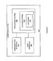
- FIG. 1is a block diagram illustrating a communication system.
- FIG. 2is a flow chart illustrating a method of selecting a wireless network.
- FIG. 3is a block diagram illustrating a communication system.
- FIG. 4is a flow chart illustrating a method of operating a communication system.
- FIG. 5is a flow chart illustrating a method of selecting a wireless network.
- FIG. 6is a block diagram of a computer system.
- a dual-mode wireless devicescans for a first type of wireless service (e.g., WiMAX or LTE). After selecting the strongest signal, the dual-mode device may request an indicator of expected service conditions. This indicator may comprise carrier-to-interference and noise ratio (CINR), expected serving modulation and coding scheme, expected air-interface throughput, network throughput, probability of being dropped, etc. Based on this indicator, the dual-mode device may decide to determine if it will be better served with a second type of wireless service (e.g., EV-DO).
- CINRcarrier-to-interference and noise ratio
- a second type of wireless servicee.g., EV-DO
- the dual-mode devicescans for the second type of wireless service. Once the dual-mode device determines the level of service it will be provided using the second type of wireless service, the dual-mode device selects between the two types of wireless services. This determination may be based on information sent to the dual-mode device by the base station. Thus, for example, a dual-mode device may find it will receive a higher throughput using WiMAX service, but will get a more reliable connection via EV-DO. In this case, the dual-mode device can select between the two services depending upon those factors that it finds are important—in this example, throughput or reliability.
- FIG. 1is a block diagram illustrating a communication system.
- communication system 100comprises base station 110 , wireless device 120 , service system 140 , and network 150 .
- Base station 110includes co-located wireless stations 111 and 112 .
- Service system 140may include database 160 .
- Base station 110is operatively coupled to network 150 .
- Network 150is operatively coupled to service system 140 .
- Wireless device 120may be operatively coupled to base station 110 via wireless link 135 and wireless station 111 .
- Wireless device 120may be operatively coupled to base station 110 via wireless link 136 and wireless station 112 .
- Wireless station 111may provide a first type of wireless service to wireless device 120 via wireless link 135 .
- wireless station 111may provide a wireless service based on orthogonal frequency division multiplexing (OFDM) or orthogonal frequency division multiple access (OFDMA).
- OFDMorthogonal frequency division multiplexing
- OFDMAorthogonal frequency division multiple access
- wireless station 111may provide a high bandwidth wireless service based on modern standards. Examples of these high bandwidth wireless services include, but are not limited to, WiMAX and LTE. Other types of high bandwidth wireless services may be provided by wireless station 111 .
- Wireless station 112may provide a second type of wireless service to wireless device 120 via wireless link 136 .
- wireless station 112may provide wireless service that is based on code division multiple access (CDMA) or time division multiple access (TDMA).
- CDMAcode division multiple access
- TDMAtime division multiple access
- wireless station 112may provide a wireless service that is based on cellular phone technology standards. Examples of wireless services based on cellular technologies include, but are not limited to, EV-DO, Global System for Mobile communications (GSM), CDMA, and TDMA. Other types of cellular technology type wireless services may be provided by wireless station 111 .
- Wireless device 120may be any device, system, combination of devices, or other such communication platform capable of communicating with base station 110 via wireless stations 111 and 112 and wireless links 135 and 136 , respectively.
- wireless links 135 and 136provide communication between wireless device 120 and wireless stations 111 and 112 using two different wireless services.
- Wireless device 120may be, for example, a mobile phone, a wireless phone, a wireless modem, a personal digital assistant (PDA), a voice over internet protocol (VoIP) phone, a voice over packet (VOP) phone, or a soft phone, as well as other types of devices or systems that can exchange data with base station 110 via wireless links.
- PDApersonal digital assistant
- VoIPvoice over internet protocol
- VOPvoice over packet
- Base station 110may be any wireless system that provides two different types of wireless service air-interfaces to wireless device 120 , and communication connectivity to network 150 .
- Wireless station 111 and wireless station 112may be any wireless system that each provide a single air-interface to wireless device 120 and communication connectivity to network 150 .
- Examples of base stations and wireless stations that may be utilizedinclude, base transceiver stations (BTSs), radio base stations (RBSs), Node B, enhanced Node B (eNBs) and others.
- Base stations and wireless stationsmay include a number of elements known to those skilled in the art comprising a transceiver, power amplifier, combiner, duplexer, antenna and control function.
- Network 150may comprise a computer, a network, or a collection of computers and networks that couple, link, or otherwise operatively provide wireless device 120 with communication service. It should be understood that network 150 may comprise secondary data networks. For example, network 150 may include a backhaul network, a local network, a long distance network, a packet network, or any combination thereof, as well as other types of networks. Network 150 may be or include an access service network (ASN), an access service network gateway (ASN-GW), wireless local access network access gateway (WAG), packet data gateway (PDG), mobile switching center (MSC) and packet data serving node (PDSN).
- ASNaccess service network
- ASN-GWaccess service network gateway
- WAGwireless local access network access gateway
- PGWpacket data gateway
- MSCmobile switching center
- PDSNpacket data serving node
- Network 150is operatively coupled to service system 140 . Since service system 140 includes database 160 , and network 150 is operatively coupled to service system 140 , network 150 is operatively coupled to database 160 . Likewise, since base station 110 is operatively coupled to network 150 , base station 110 (and thus wireless stations 111 and 112 ) may be operatively coupled to database 160 .
- Service system 140may be any system or collection of systems, such as database 160 , capable of storing and retrieving information about at least one of: (a) services provided by network 150 ; (b) services provided by or to networks, users, or a wireless device 120 connected to network 150 ; (c) configuration information for network 150 ; or, (d) configuration or capabilities associated with a wireless device 120 .
- service system 140is part of a connectivity service network (CSN) and performs authentication, authorization, and accounting operations.
- service system 140is a device capabilities server (DCS) and provides information about wireless device 120 .
- Service system 140may manage user or device profiles for authentication (e.g., verifying device identifier, user name, or password).
- Service system 140may provide configuration information to network 150 or base station 110 that specifies a type of service to deliver, and policies to enforce that may restrict access by, or services provided to, wireless device 120 .
- wireless device 120may send a registration message to network 150 asking for permission to use base station 110 and network 150 to communicate to other systems.
- Wireless device 120may send a registration message via an access channel.
- the registration messagemay include a device identifier.
- Network 150may then forward that registration message, along with a device identifier to service system 140 .
- Service system 140may then query database 160 with the device identifier to determine if wireless device 120 may use base station 110 and network 150 .
- Service system 140may then inform base station 110 and network 150 whether wireless device 120 may use network 150 .
- a device identifiermay be one or more of, but is not limited to, a mobile phone number, a mobile directory number (MDN), mobile identification number (MIN), electronic serial number (ESN), medium access control address (MAC address), or internet protocol address (IP address). Other types of device identifiers are also possible.
- Service system 140may also query database 160 to provide configuration information to base station 110 and network 150 that determines how wireless device 120 may use base station 110 and network 150 .
- service system 140may configure base station 110 to allow wireless device 120 request a desired signal strength, modulation and coding scheme (MCS), throughput rate, available throughput and/or network loading during the initial connection process.
- MCSmodulation and coding scheme
- MCSmodulation and coding scheme
- DRCdata rate control
- wireless device 120may scan for a wireless service of a first type.
- Wireless device 120may scan for the wireless service of the first type for a first predetermined period of time. For example, wireless device 120 may first scan for a wireless service of the type provided by wireless station 111 . The scanning process may result in wireless device 120 selecting wireless station 111 .
- Wireless device 120may select wireless station 111 as the first wireless station to provide an indicator of expected service conditions.
- Wireless device 120may initiate the initial connection process with wireless station 111 . During this initial connection process, wireless device 120 may request an indicator of expected service conditions. Wireless device 120 may send a request for an indicator of expected service conditions via an access channel.
- wireless device 120may request one or more of a desired signal strength, modulation and coding scheme (MCS), throughput rate, available throughput and/or network loading.
- MCSmodulation and coding scheme
- wireless station 111 , base station 110 , or network 150may provide a first indicator of expected service conditions.
- This first indicator of expected service conditionsmay be received by wireless device 120 via wireless link 135 .
- This first indicator of expected service conditionsmay be received by wireless device 120 via an access channel.
- wireless device 120may scan for a wireless service of the second type.
- Wireless device 120may scan for the wireless service of the second type for a second predetermined period of time. For example, if wireless station 111 sends a first indicator of expected service conditions associated with an MCS, and that MCS is not adequate for wireless device 120 's requirements, then wireless device 120 may scan for the second type of wireless service provided by wireless station 112 .
- wireless device 120may determine to scan for a second type of wireless service based on one or more received indicators of expected service conditions associated with, for example, signal strength, throughput rate, available throughput and/or network loading.
- the process of scanning for a second type of wireless servicemay result in wireless device 120 selecting wireless station 112 .
- Wireless device 120may select wireless station 112 to provide an indicator of expected service conditions.
- Wireless device 120may initiate the initial connection process with wireless station 112 .
- wireless device 120may request an indicator of expected service conditions.
- Wireless device 120may send this request for an indicator of expected service conditions via an access channel.
- one or more of wireless station 112 , base station 110 , or network 150may provide a second indicator of expected service conditions.
- This second indicator of expected service conditionsmay be received by wireless device 120 via wireless link 136 .
- Wireless device 120may receive this second indicator of expected service conditions via an access channel.
- wireless device 120may select one of the first type of wireless service or the second type of wireless service. For example, based on the first indicator and the second indicator, wireless device 120 may select between wireless station 111 and wireless station 112 to provide wireless service to wireless device 120 .
- FIG. 2is a flow chart illustrating a method of selecting a wireless network. The steps illustrated in FIG. 2 may be performed by one or more elements of communication system 100 .
- a wireless service of a first typeis scanned ( 202 ).
- wireless device 120may scan for a wireless service of a first type.
- This first type of wireless servicemay be the type of wireless service provided by wireless station 111 .
- a first wireless station associated with the first type of wireless serviceis selected ( 204 ).
- wireless device 120may select wireless station 111 . This selection may be based on a received signal strength associated with wireless station 111 .
- a first indicator of expected service conditions associated with the first stationis received ( 206 ).
- wireless device 120may receive a first indicator of expected service conditions via wireless link 135 .
- This first indicator of expected service conditionsmay be associated with one or more of: signal strength, MCS, throughput rate, available throughput, and/or network loading.
- a wireless service of the second typeis scanned for based on the first indicator ( 208 ). For example, based on the first indicator, wireless device 120 may scan for a second type of wireless service.
- the second type of wireless servicemay be the type of wireless service provided by wireless station 112 .
- Wireless device 120may decide to scan for the second type of wireless service because the first indicator was associated with a level of wireless service that would not meet wireless device 120 's desired service level.
- a second station associated with the second type of wireless serviceis selected ( 210 ).
- wireless device 120may select wireless station 112 . This selection may be based on a received signal strength.
- a second indicator of expected service conditions associated with the second stationis received ( 212 ).
- wireless device 120may receive a second indicator of expected service conditions associated with wireless station 112 .
- This second indicator of expected service conditionsmay be associated with one or more of: signal strength, MCS, throughput rate, available throughput and/or network loading.
- the first type or the second type of wireless serviceis selected to provide wireless service ( 214 ). For example, based on the first and second indicators wireless device 120 may select one of wireless station 111 and wireless station 112 to provide wireless service to wireless device 120 . This selection may be based on which of wireless station 111 and wireless station 112 is best able to provide the service conditions that wireless device 120 desires and/or requires.
- FIG. 3is a block diagram illustrating a communication system.
- communication system 300comprises base station 310 , base station 311 , base station 312 , base station 313 , wireless device 320 , service system 340 , and network 350 .
- Base station 310is operatively coupled to network 350 .
- Base station 312is operatively coupled to network 350 .
- Network 350is operatively coupled to service system 340 .
- Wireless device 320may be operatively coupled to base stations 310 - 313 via wireless links.
- Base stations 310 and 311may provide a first type of wireless service.
- base stations 310 and 311may provide a wireless service based on OFDM or OFDMA.
- base stations 310 and 311may provide a high bandwidth wireless service based on modern standards. Examples of these high bandwidth wireless services include, but are not limited to, WiMAX and LTE. Other types of high bandwidth wireless services may be provided by base stations 310 and 311 .
- Base stations 312 and 313may provide a second type of wireless.
- base stations 312 and 313may provide wireless service that is based on CDMA or TDMA.
- base stations 312 and 313may provide a wireless service that is based on cellular phone technology standards. Examples of wireless services based on cellular technologies include, but are not limited to, EV-DO, Global System for Mobile communications (GSM), CDMA, and TDMA. Other types of cellular technology type wireless services may be provided by base stations 312 and 313 .
- Wireless device 320may be any device, system, combination of devices, or other such communication platform capable of communicating with base stations 310 and 311 using a first type of wireless service, and base station 312 and 313 using a second type of wireless service.
- Wireless device 320may be, for example, a mobile phone, a wireless phone, a wireless modem, a personal digital assistant (PDA), a voice over internet protocol (VoIP) phone, a voice over packet (VOP) phone, or a soft phone, as well as other types of devices or systems that can exchange data with base stations 310 - 313 via wireless links.
- PDApersonal digital assistant
- VoIPvoice over internet protocol
- VOPvoice over packet
- Soft phonea soft phone
- Base stations 310 and 311may be any wireless system that provides a first type of wireless service air-interface to wireless device 320 , and communication connectivity to network 150 .
- Base stations 312 and 313may be any wireless system that provides a second type of wireless service air-interface to wireless device 320 , and communication connectivity to network 150 . Examples of base stations that may be utilized include, base transceiver stations (BTSs), radio base stations (RBSs), Node B, enhanced Node B (eNBs) and others.
- Base stationsmay include a number of elements known to those skilled in the art comprising a transceiver, power amplifier, combiner, duplexer, antenna and control function.
- Network 350may comprise a computer, a network, or a collection of computers and networks that couple, link, or otherwise operatively provide wireless device 320 with communication service. It should be understood that network 350 may comprise secondary data networks.
- network 350may include a backhaul network, a local network, a long distance network, a packet network, or any combination thereof, as well as other types of networks.
- Network 350may be or include an access service network (ASN), an access service network gateway (ASN-GW), wireless local access network access gateway (WAG), packet data gateway (PDG), mobile switching center (MSC) and packet data serving node (PDSN).
- ASNaccess service network
- ASN-GWaccess service network gateway
- WAGwireless local access network access gateway
- PGWpacket data gateway
- MSCmobile switching center
- PDSNpacket data serving node
- Network 350is operatively coupled to service system 340 . Since base stations 310 - 313 are operatively coupled to network 350 , base stations 310 - 313 may be operatively coupled to service system 340 .
- Service system 340may be any system or collection of systems, such as a database, capable of storing and retrieving information about at least one of: (a) services provided by network 350 ; (b) services provided by or to networks, users, or wireless device 320 connected to network 350 ; (c) configuration information for network 350 ; or, (d) configuration or capabilities associated with a wireless device 320 .
- service system 340is part of a CSN and performs authentication, authorization, and accounting operations.
- service system 340is a device capabilities server (DCS) and provides information about wireless device 320 .
- Service system 340may manage user or device profiles for authentication (e.g., verifying device identifier, user name, or password).
- Service system 340may provide configuration information to network 350 or base stations 310 - 313 that specifies a type of service to deliver, and policies to enforce that may restrict access by, or services provided to, wireless device 320 .
- wireless device 320may send a registration message to network 350 asking for permission to use base station 310 and network 350 to communicate to other systems. This registration message may be sent via an access channel.
- the registration messagemay include a device identifier.
- Network 350may then forward that registration message, along with a device identifier to service system 340 .
- Service system 340may then determine if wireless device 320 may use base station 310 and network 350 .
- Service system 340may then inform base station 310 and network 350 whether wireless device 320 may use network 350 .
- a device identifiermay be one or more, but is not limited to, a mobile phone number, a mobile directory number (MDN), mobile identification number (MIN), electronic serial number (ESN), medium access control address (MAC address), or internet protocol address (IP address). Other types of device identifiers are also possible.
- MDNmobile directory number
- MINmobile identification number
- ESNelectronic serial number
- MAC addressmedium access control address
- IP addressinternet protocol address
- Service system 340may also provide configuration information to base station 310 and network 350 that determines how wireless device 320 may use base station 310 and network 350 .
- service system 340may configure base station 310 to allow wireless device 320 request a desired signal strength, modulation and coding scheme (MCS), throughput rate, available throughput and/or network loading during the initial connection process.
- MCSmodulation and coding scheme
- Base station 310may be configured to allow one or more of these requests to be received via an access channel.
- wireless device 320would not have to wait for the connection to be established and then send a request for desired service conditions.
- wireless device 320would not have to wait for the connection to be established to then send a data rate control (DRC) request.
- DRCdata rate control
- wireless device 320may scan for a wireless service of a first type.
- Wireless device 320may scan for the wireless service of the first type for a first predetermined period of time. For example, wireless device 320 may first scan for a wireless service of the type provided by base station 310 . The scanning process may result in wireless device 320 selecting base station 310 .
- Wireless device 320may select base station 310 to provide an indicator of expected service conditions.
- Wireless device 320may initiate the initial connection process with base station 310 . During this initial connection process, wireless device 320 may request an indicator of expected service conditions. For example, wireless device 320 may request one or more of a desired signal strength, modulation and coding scheme (MCS), throughput rate, available throughput and/or network loading.
- MCSmodulation and coding scheme
- This requestmay be sent via an access channel.
- base station 310or network 150 , may provide a first indicator of expected service conditions.
- This first indicator of expected service conditionsmay be received by wireless device 320 via a wireless link.
- This first indicator of expected service conditionsmay be received via an access channel.
- wireless device 320may scan for a wireless service of the second type.
- Wireless device 320may scan for the wireless service of the second type for a second predetermined period of time. For example, if base station 310 sends a first indicator of expected service conditions associated with an MCS, and that MCS is not adequate for wireless device 320 's requirements, then wireless device 320 may scan for a type of wireless service provided by base stations 312 and 313 .
- Wireless device 320may determine to scan for a second type of wireless service based on received indicators of expected service conditions associated with signal strength, throughput rate, available throughput and/or network loading.
- the process of scanning for a second type of wireless servicemay result in wireless device 320 selecting base station 312 .
- Wireless device 320may select station 312 to provide an indicator of expected service conditions.
- Wireless device 320may initiate the initial connection process with station 312 .
- wireless device 320may request an indicator of expected service conditions. This request may be made via an access channel.
- base station 312 , or network 350may provide a second indicator of expected service conditions. This second indicator of expected service conditions may be received by wireless device 320 via a wireless link. This second indicator of expected service conditions may be received via an access channel.
- wireless device 320may select one of the first type of wireless service or the second type of wireless service. For example, based on the first indicator and the second indicator wireless device 320 may select between station 310 and base station 312 to provide wireless service.
- FIG. 4is a flow chart illustrating a method of selecting a wireless network. The steps illustrated in FIG. 4 may be performed by one or more elements of communication system 100 or communication system 300 .
- a connection request from a wireless deviceis received ( 402 ).
- base station 310may receive a wireless service connection request from wireless device 320 .
- the profile associated with the wireless deviceis determined ( 404 ).
- service system 340may determine a profile associated with wireless device 320 . This profile a be associated with a user profile or service level that allows wireless device 320 to request a desired MCS, throughput rate, signal strength, network loading, and/or available throughput.
- the wireless deviceis allowed to request a first indicator of expected service conditions associated with the first type of wireless service ( 406 ). For example, based on the profile received from service system 340 , base station 310 may allow wireless device 320 request a first indicator of expected service conditions. Base station 310 may allow wireless device 320 to request the first indicator of expected service conditions via an access channel.
- the first indicator of expected service conditionsis sent to the wireless device ( 408 ).
- base station 310may send you the first indicator of expected service conditions to wireless device 320 via a wireless link. This wireless link may be via an access channel.
- a second connection request from the wireless deviceis received ( 410 ).
- base station 312may receive a connection request, on an access channel, from wireless device 320 .
- This connection requestmay have been sent by wireless device 320 because the first indicator of expected service conditions failed to meet a minimum level of service required, or expected, by wireless device 320 .
- a second indicator of expected service conditionsis sent to the wireless device ( 412 ).
- base station 312may send an indicator of expected service conditions to wireless device 320 .
- These expected service conditionsmay be associated with a second type of wireless service as provided by base station 312 .
- the indicator of expected service conditionsmay be sent in response to a request by wireless device 320 .
- wireless device 320may select at a base station 310 or 312 to provide wireless service, or choose to continue scanning for other base stations.
- Wireless device 320may scan for base stations, such as base station 311 and base station 313 , that may be able to provide satisfactory service conditions.
- FIG. 5is a flow chart illustrating a method of selecting a wireless network. The steps illustrated in FIG. 5 may be performed by one or more elements of communication system 100 or communication system 300 .
- a first wireless service typeis scanned ( 502 ).
- wireless device 320may scan for the type of wireless service provided by base stations 310 and 311 .
- a first station for the first wireless service typeis selected ( 504 ).
- wireless device 320may select base station 310 over base station 311 . This selection may be based on signal strength or other factors.
- first stationis capable of a requested service level
- flowproceeds to block 508 .
- first stationis not capable of the requested service level
- flowproceeds to block 510 ( 506 ).
- base station 310is capable of providing a requested service level then flow would proceed to block 508 .
- wireless device 320would connect to the first station using the first wireless service type.
- base station 310is capable of providing a service level requested by wireless device 320
- wireless device 320would connect base station 310 .
- Wireless device 320may determine if base station 310 is capable of providing an adequate service level based on a received indicator of expected service conditions.
- a second wireless service typeis scanned ( 510 ).
- wireless device 320may scan for the type of wireless service provided by base stations 312 and 313 .
- a second station for the second wireless service typeis selected ( 512 ).
- wireless device 320may select base station 312 over base station 313 . This selection may be based on signal strength or other factors.
- the second stationis capable of a requested service level, flow proceeds to block 516 . If the second station is not capable of the requested service level, flow proceeds to block 518 ( 514 ). For example, if base station 312 is capable of providing a requested service level, then flow would proceed to block 516 . In block 516 , wireless device 320 would connect to the second station using the second wireless service type. In other words, if base station 312 is capable of providing a service level requested by wireless device 320 , then wireless device 320 would connect base station 312 . Wireless device 320 may determine if base station 312 is capable of providing an adequate service level based on a received indicator of expected service conditions.
- Scanningis continued ( 518 ). For example, because neither base station 310 or base station 312 were able to provide an adequate service level, wireless device 320 may continue to scan for wireless services of the first type and the second type. Thus, flow may proceed back to block 502 . In this case, wireless device 320 may select base station 311 over base station 310 because it already knows that base station 310 cannot provide the requested service level. Likewise, wireless device 320 may select base station 313 over base station 312 because it already knows that base station 312 cannot provide the requested service level.
- the methods, systems, devices, networks, databases, wireless stations, and base stations described abovemay be implemented with, contain, or be executed by one or more computer systems. The methods described above may also be stored on a computer readable medium. Many of the elements of communication network 100 and communication network 300 may be, comprise, or include computers systems. This includes, but is not limited to: communication system 100 , base station 110 , wireless device 120 , service system 140 , database 160 , network 150 , wireless stations 111 , wireless station 112 , communication system 300 , base station 310 , base station 311 , base station 312 , base station 313 , wireless device 320 , service system 340 , and network 350 .
- FIG. 6illustrates a block diagram of a computer system.
- Computer system 600includes communication interface 620 , processing system 630 , and user interface 660 .
- Processing system 630includes storage system 640 .
- Storage system 640stores software 650 .
- Processing system 630is linked to communication interface 620 and user interface 660 .
- Computer system 600could be comprised of a programmed general-purpose computer, although those skilled in the art will appreciate that programmable or special purpose circuitry and equipment may be used.
- Computer system 600may be distributed among multiple devices that together comprise elements 620 - 660 .
- Communication interface 620could comprise a network interface, modem, port, transceiver, or some other communication device. Communication interface 620 may be distributed among multiple communication devices.
- Processing system 630could comprise a computer microprocessor, logic circuit, or some other processing device. Processing system 630 may be distributed among multiple processing devices.
- User interface 660could comprise a keyboard, mouse, voice recognition interface, microphone and speakers, graphical display, touch screen, or some other type of user device. User interface 660 may be distributed among multiple user devices.
- Storage system 640may comprise a disk, tape, integrated circuit, server, or some other memory device. Storage system 640 may be distributed among multiple memory devices.
- Processing system 630retrieves and executes software 650 from storage system 640 .
- Software 650may comprise an operating system, utilities, drivers, networking software, and other software typically loaded onto a computer system.
- Software 650may comprise an application program, firmware, or some other form of machine-readable processing instructions. When executed by processing system 630 , software 650 directs processing system 630 to operate as described herein.
Landscapes
- Engineering & Computer Science (AREA)
- Computer Security & Cryptography (AREA)
- Computer Networks & Wireless Communication (AREA)
- Signal Processing (AREA)
- Mobile Radio Communication Systems (AREA)
Abstract
Description
Claims (20)
Priority Applications (2)
| Application Number | Priority Date | Filing Date | Title |
|---|---|---|---|
| US12/423,101US8538422B1 (en) | 2009-04-14 | 2009-04-14 | Reallocation of resources for dual-mode wireless devices |
| US13/963,492US9301244B2 (en) | 2009-04-14 | 2013-08-09 | Reallocation of resources for dual-mode wireless devices |
Applications Claiming Priority (1)
| Application Number | Priority Date | Filing Date | Title |
|---|---|---|---|
| US12/423,101US8538422B1 (en) | 2009-04-14 | 2009-04-14 | Reallocation of resources for dual-mode wireless devices |
Related Child Applications (1)
| Application Number | Title | Priority Date | Filing Date |
|---|---|---|---|
| US13/963,492ContinuationUS9301244B2 (en) | 2009-04-14 | 2013-08-09 | Reallocation of resources for dual-mode wireless devices |
Publications (1)
| Publication Number | Publication Date |
|---|---|
| US8538422B1true US8538422B1 (en) | 2013-09-17 |
Family
ID=49122453
Family Applications (2)
| Application Number | Title | Priority Date | Filing Date |
|---|---|---|---|
| US12/423,101Active2031-02-25US8538422B1 (en) | 2009-04-14 | 2009-04-14 | Reallocation of resources for dual-mode wireless devices |
| US13/963,492Active2029-11-07US9301244B2 (en) | 2009-04-14 | 2013-08-09 | Reallocation of resources for dual-mode wireless devices |
Family Applications After (1)
| Application Number | Title | Priority Date | Filing Date |
|---|---|---|---|
| US13/963,492Active2029-11-07US9301244B2 (en) | 2009-04-14 | 2013-08-09 | Reallocation of resources for dual-mode wireless devices |
Country Status (1)
| Country | Link |
|---|---|
| US (2) | US8538422B1 (en) |
Families Citing this family (1)
| Publication number | Priority date | Publication date | Assignee | Title |
|---|---|---|---|---|
| US9713083B2 (en)* | 2013-08-28 | 2017-07-18 | Noki Technologies Oy | LTE advanced service indicator |
Citations (63)
| Publication number | Priority date | Publication date | Assignee | Title |
|---|---|---|---|---|
| US5020093A (en) | 1989-06-23 | 1991-05-28 | Motorola, Inc. | Cellular telephone operable on different cellular telephone systems |
| US5020092A (en) | 1989-06-23 | 1991-05-28 | Motorola, Inc. | Dual-bandwidth cellular telephone |
| GB2288301A (en) | 1994-04-05 | 1995-10-11 | Motorola Inc | Methods and apparatus for call handover between different mobile radio networks |
| US5550895A (en) | 1993-12-02 | 1996-08-27 | Lucent Technologies Inc. | Bimodal portable telephone |
| US5594782A (en) | 1994-02-24 | 1997-01-14 | Gte Mobile Communications Service Corporation | Multiple mode personal wireless communications system |
| US5640686A (en) | 1994-05-13 | 1997-06-17 | Nec Corporation | Radio communication device capable of communication in a plurality of communication systems |
| US5754542A (en) | 1995-07-31 | 1998-05-19 | Qualcomm Incorporated | Method and apparatus for system determination in a multi-mode subscriber station |
| US5870673A (en) | 1996-08-30 | 1999-02-09 | Telefonaktiebolaget Lm Ericsson | Methods and systems for concurrent receipt of incoming calls from a wide area cellular network and a private radio communications network |
| US5966667A (en) | 1997-07-14 | 1999-10-12 | Motorola, Inc. | Dual mode communication device and method |
| US5987334A (en) | 1996-02-27 | 1999-11-16 | Nec Corporation | Multi-modal handy phone |
| US6006106A (en) | 1996-12-31 | 1999-12-21 | Ericsson Inc. | Method for automatic transceiver selection in a mobile multiple RF transceiver apparatus |
| US6011978A (en) | 1997-03-07 | 2000-01-04 | Qualcomm Incorporated | Automatic system switching in a multiple-mode wireless communication device |
| US6112088A (en) | 1996-08-30 | 2000-08-29 | Telefonaktiebolaget, L.M. Ericsson | Radio communications system and method for mobile assisted handover between a private network and a public mobile network |
| US6125283A (en) | 1998-05-18 | 2000-09-26 | Ericsson Inc. | Multi-mode mobile terminal and methods for operating the same |
| US6198941B1 (en) | 1998-08-07 | 2001-03-06 | Lucent Technologies Inc. | Method of operating a portable communication device |
| US6201963B1 (en) | 1997-04-11 | 2001-03-13 | Nec Corporation | Mobile communication system |
| US6304761B1 (en) | 1996-05-31 | 2001-10-16 | Matsushita Electric Industrial Co., Ltd. | Mobile unit communication apparatus having digital and analog communication modes and a method of controlling the same |
| US6317582B1 (en) | 1999-05-11 | 2001-11-13 | Kyocera Corporation | Multimode mobile telephone apparatus |
| US20020039892A1 (en) | 2000-10-04 | 2002-04-04 | Bo Lindell | System and method for network and service selection in a mobile communication station |
| US20020059453A1 (en) | 2000-11-13 | 2002-05-16 | Eriksson Goran A. P. | Access point discovery and selection |
| US6400961B1 (en) | 1996-12-19 | 2002-06-04 | Infineon Technologies Ag | Method and apparatus for reducing the power consumption of mobile multimode communication terminals |
| US20020085516A1 (en) | 2000-12-28 | 2002-07-04 | Symbol Technologies, Inc. | Automatic and seamless vertical roaming between wireless local area network (WLAN) and wireless wide area network (WWAN) while maintaining an active voice or streaming data connection: systems, methods and program products |
| US6456858B1 (en) | 1998-12-21 | 2002-09-24 | Verizon Wireless | System and methods in a dual mode wireless system for transmitting rescan command based on detected network conditions |
| US20020147008A1 (en) | 2001-01-29 | 2002-10-10 | Janne Kallio | GSM Networks and solutions for providing seamless mobility between GSM Networks and different radio networks |
| US20020173303A1 (en) | 2001-05-16 | 2002-11-21 | Docomo Communications Laboratories Usa, Inc. | Wireless communication system |
| US6498939B1 (en) | 1999-07-20 | 2002-12-24 | Texas Instruments Incorporated | Wireless network |
| US20030003869A1 (en) | 2001-06-28 | 2003-01-02 | Nec Corporation | Mobile radiotelephone connecting apparatus and mobile radiotelephone connecting system |
| US20030003910A1 (en)* | 2001-06-28 | 2003-01-02 | Mcclure Kenneth | Network assisted background scanning for mobile stations |
| US20030017842A1 (en) | 1999-05-24 | 2003-01-23 | Bryan Jeffery Moles | Wireless network system selection mechanism within a mobile station |
| US6526034B1 (en) | 1999-09-21 | 2003-02-25 | Tantivy Communications, Inc. | Dual mode subscriber unit for short range, high rate and long range, lower rate data communications |
| US20030039242A1 (en) | 2001-07-06 | 2003-02-27 | General Instrument Corporation | Methods, apparatus,and systems for accessing mobile and voice over IP telephone networks with a mobile handset |
| US20030224795A1 (en) | 2000-12-14 | 2003-12-04 | Bridgeport Networks, Inc. | Circuit switched cellular network to internet calling with internet antennas |
| US6680923B1 (en) | 2000-05-23 | 2004-01-20 | Calypso Wireless, Inc. | Communication system and method |
| US20040146021A1 (en) | 2003-01-23 | 2004-07-29 | Fors Chad M. | Method and apparatus for a source-initiated handoff from a source cellular wireless network to a target non-cellular wireless network |
| US20040170191A1 (en)* | 2003-02-28 | 2004-09-02 | Microsoft Corporation | Vertical roaming in wireless networks through improved quality of service measures |
| US6804532B1 (en) | 2000-12-22 | 2004-10-12 | Cisco Technology, Inc. | System and method for re-routing communications based on wireless communication link quality |
| US20040203791A1 (en) | 2002-06-26 | 2004-10-14 | Pan Shaowei | Method and apparatus for implementing bi-directional soft handovers between wireless networks via mobile station control |
| US20040203789A1 (en) | 2002-11-12 | 2004-10-14 | Hammond Marc John | Location service assisted transition between wireless networks |
| US6862277B2 (en) | 2002-10-28 | 2005-03-01 | Motorola, Inc. | Method and apparatus for multi-media communication over multiple networks |
| US20050083899A1 (en)* | 2003-10-17 | 2005-04-21 | Uppinder Babbar | System selection for wireless data services |
| US6895255B1 (en) | 2000-10-20 | 2005-05-17 | Symbol Technologies, Inc. | Dual mode wireless data communications |
| US20050119001A1 (en)* | 2003-11-28 | 2005-06-02 | Hitachi Communication Technologies, Ltd. | Wireless communication system, server and mobile station therefor |
| US20050136937A1 (en)* | 2003-10-14 | 2005-06-23 | Feng Qian | Mobile station connection management utilizing suitable parameter information |
| US20050147068A1 (en) | 2003-12-19 | 2005-07-07 | Samsung Electronics Co., Ltd. | Apparatus and method for interworking CDMA2000 networks and wireless local area networks |
| US6922559B2 (en) | 2001-02-26 | 2005-07-26 | Kineto Wireless, Inc. | Unlicensed wireless communications base station to facilitate unlicensed and licensed wireless communications with a subscriber device, and method of operation |
| US6990598B2 (en) | 2001-03-21 | 2006-01-24 | Gallitzin Allegheny Llc | Low power reconfigurable systems and methods |
| US20060083199A1 (en) | 2004-10-15 | 2006-04-20 | Yang Jianhao M | System, method, and device for handing off between voice over internet protocol over wireless access sessions and CDMA circuit switched voice sessions |
| US20060111112A1 (en) | 2004-10-22 | 2006-05-25 | Santera Systems, Inc. | Mobility management apparatus and methods |
| US20060116127A1 (en) | 2004-07-16 | 2006-06-01 | Wilhoite Michael T | Handoff for cellular and internet protocol telephony |
| US7114010B2 (en) | 2000-06-28 | 2006-09-26 | Broadcom Corporation | Multi-mode controller |
| US7139587B2 (en) | 2003-05-23 | 2006-11-21 | Sharp Laboratories Of America, Inc. | Method and apparatus for system selection |
| US7142882B2 (en) | 2001-03-09 | 2006-11-28 | Schmidt Dominik J | Single chip wireless communication integrated circuit |
| US20060268928A1 (en)* | 2005-05-17 | 2006-11-30 | Farhad Barzegar | Method and apparatus for routing a call to a dual mode wireless device |
| US7149521B2 (en) | 2002-01-02 | 2006-12-12 | Winphoria Networks, Inc. | Method, system and apparatus for providing mobility management of a mobile station in WLAN and WWAN environments |
| US20070076664A1 (en) | 2005-09-30 | 2007-04-05 | Yafan An | Handoff decision making for heterogeneous network environments |
| US7298763B2 (en) | 1998-03-30 | 2007-11-20 | Genesys Telecommunications Laboratories, Inc | Managing bandwidth on demand for internet protocol messaging with capability for transforming telephony calls from one media type to another media type |
| US20080051130A1 (en) | 2006-08-24 | 2008-02-28 | Anupam Juneja | Software architecture for dual mode phone and method of use |
| US20080096560A1 (en) | 2006-10-24 | 2008-04-24 | Nortel Networks Limited | System and method for ensuring handoffs across heterogeneous networks |
| US20080254797A1 (en) | 2007-04-11 | 2008-10-16 | Nortel Networks Limited | Seamless and vertical call handoff solution architecture |
| US20090023446A1 (en)* | 2007-07-20 | 2009-01-22 | General Motors Corporation | Service Provider Initiated Access Network Selection |
| US20090047946A1 (en)* | 2005-09-16 | 2009-02-19 | Matsushita Electric Industrial Co., Ltd. | Mobile communication composite terminal apparatus and mobile communication terminal apparatus |
| US7702357B2 (en)* | 2002-11-26 | 2010-04-20 | Sony Corporation | Wireless intelligent switch engine |
| US8229433B2 (en)* | 2005-10-27 | 2012-07-24 | Qualcomm Incorporated | Inter-frequency handoff |
Family Cites Families (5)
| Publication number | Priority date | Publication date | Assignee | Title |
|---|---|---|---|---|
| AU3038100A (en) | 1999-12-13 | 2001-06-25 | Nokia Corporation | Congestion control method for a packet-switched network |
| GB2359220A (en) | 2000-02-03 | 2001-08-15 | Orange Personal Comm Serv Ltd | Handover in accordance with a network policy |
| US8538430B1 (en)* | 2007-03-22 | 2013-09-17 | Apple Inc. | System and method for handoff of mobile terminals between different wireless access network technologies |
| US8699450B2 (en)* | 2008-05-11 | 2014-04-15 | Qualcomm Incorporated | Systems and methods for multimode wireless communication handoff |
| US20090290555A1 (en)* | 2008-05-21 | 2009-11-26 | Comsys Communication & Signal Processing Ltd. | Autonomous anonymous association between a mobile station and multiple network elements in a wireless communication system |
- 2009
- 2009-04-14USUS12/423,101patent/US8538422B1/enactiveActive
- 2013
- 2013-08-09USUS13/963,492patent/US9301244B2/enactiveActive
Patent Citations (67)
| Publication number | Priority date | Publication date | Assignee | Title |
|---|---|---|---|---|
| US5020092A (en) | 1989-06-23 | 1991-05-28 | Motorola, Inc. | Dual-bandwidth cellular telephone |
| US5020093A (en) | 1989-06-23 | 1991-05-28 | Motorola, Inc. | Cellular telephone operable on different cellular telephone systems |
| US5550895A (en) | 1993-12-02 | 1996-08-27 | Lucent Technologies Inc. | Bimodal portable telephone |
| US5594782A (en) | 1994-02-24 | 1997-01-14 | Gte Mobile Communications Service Corporation | Multiple mode personal wireless communications system |
| GB2288301A (en) | 1994-04-05 | 1995-10-11 | Motorola Inc | Methods and apparatus for call handover between different mobile radio networks |
| US5640686A (en) | 1994-05-13 | 1997-06-17 | Nec Corporation | Radio communication device capable of communication in a plurality of communication systems |
| US5754542A (en) | 1995-07-31 | 1998-05-19 | Qualcomm Incorporated | Method and apparatus for system determination in a multi-mode subscriber station |
| US5987334A (en) | 1996-02-27 | 1999-11-16 | Nec Corporation | Multi-modal handy phone |
| US6304761B1 (en) | 1996-05-31 | 2001-10-16 | Matsushita Electric Industrial Co., Ltd. | Mobile unit communication apparatus having digital and analog communication modes and a method of controlling the same |
| US6112088A (en) | 1996-08-30 | 2000-08-29 | Telefonaktiebolaget, L.M. Ericsson | Radio communications system and method for mobile assisted handover between a private network and a public mobile network |
| US5870673A (en) | 1996-08-30 | 1999-02-09 | Telefonaktiebolaget Lm Ericsson | Methods and systems for concurrent receipt of incoming calls from a wide area cellular network and a private radio communications network |
| US6400961B1 (en) | 1996-12-19 | 2002-06-04 | Infineon Technologies Ag | Method and apparatus for reducing the power consumption of mobile multimode communication terminals |
| US6006106A (en) | 1996-12-31 | 1999-12-21 | Ericsson Inc. | Method for automatic transceiver selection in a mobile multiple RF transceiver apparatus |
| US6011978A (en) | 1997-03-07 | 2000-01-04 | Qualcomm Incorporated | Automatic system switching in a multiple-mode wireless communication device |
| US6201963B1 (en) | 1997-04-11 | 2001-03-13 | Nec Corporation | Mobile communication system |
| US5966667A (en) | 1997-07-14 | 1999-10-12 | Motorola, Inc. | Dual mode communication device and method |
| US7298763B2 (en) | 1998-03-30 | 2007-11-20 | Genesys Telecommunications Laboratories, Inc | Managing bandwidth on demand for internet protocol messaging with capability for transforming telephony calls from one media type to another media type |
| US6125283A (en) | 1998-05-18 | 2000-09-26 | Ericsson Inc. | Multi-mode mobile terminal and methods for operating the same |
| US6198941B1 (en) | 1998-08-07 | 2001-03-06 | Lucent Technologies Inc. | Method of operating a portable communication device |
| US6456858B1 (en) | 1998-12-21 | 2002-09-24 | Verizon Wireless | System and methods in a dual mode wireless system for transmitting rescan command based on detected network conditions |
| US6317582B1 (en) | 1999-05-11 | 2001-11-13 | Kyocera Corporation | Multimode mobile telephone apparatus |
| US20030017842A1 (en) | 1999-05-24 | 2003-01-23 | Bryan Jeffery Moles | Wireless network system selection mechanism within a mobile station |
| US6498939B1 (en) | 1999-07-20 | 2002-12-24 | Texas Instruments Incorporated | Wireless network |
| US6526034B1 (en) | 1999-09-21 | 2003-02-25 | Tantivy Communications, Inc. | Dual mode subscriber unit for short range, high rate and long range, lower rate data communications |
| US6680923B1 (en) | 2000-05-23 | 2004-01-20 | Calypso Wireless, Inc. | Communication system and method |
| US7114010B2 (en) | 2000-06-28 | 2006-09-26 | Broadcom Corporation | Multi-mode controller |
| US20020039892A1 (en) | 2000-10-04 | 2002-04-04 | Bo Lindell | System and method for network and service selection in a mobile communication station |
| US6895255B1 (en) | 2000-10-20 | 2005-05-17 | Symbol Technologies, Inc. | Dual mode wireless data communications |
| US20020059453A1 (en) | 2000-11-13 | 2002-05-16 | Eriksson Goran A. P. | Access point discovery and selection |
| US20030224795A1 (en) | 2000-12-14 | 2003-12-04 | Bridgeport Networks, Inc. | Circuit switched cellular network to internet calling with internet antennas |
| US6804532B1 (en) | 2000-12-22 | 2004-10-12 | Cisco Technology, Inc. | System and method for re-routing communications based on wireless communication link quality |
| US20020085516A1 (en) | 2000-12-28 | 2002-07-04 | Symbol Technologies, Inc. | Automatic and seamless vertical roaming between wireless local area network (WLAN) and wireless wide area network (WWAN) while maintaining an active voice or streaming data connection: systems, methods and program products |
| US7039027B2 (en) | 2000-12-28 | 2006-05-02 | Symbol Technologies, Inc. | Automatic and seamless vertical roaming between wireless local area network (WLAN) and wireless wide area network (WWAN) while maintaining an active voice or streaming data connection: systems, methods and program products |
| US20020147008A1 (en) | 2001-01-29 | 2002-10-10 | Janne Kallio | GSM Networks and solutions for providing seamless mobility between GSM Networks and different radio networks |
| US6922559B2 (en) | 2001-02-26 | 2005-07-26 | Kineto Wireless, Inc. | Unlicensed wireless communications base station to facilitate unlicensed and licensed wireless communications with a subscriber device, and method of operation |
| US7142882B2 (en) | 2001-03-09 | 2006-11-28 | Schmidt Dominik J | Single chip wireless communication integrated circuit |
| US6990598B2 (en) | 2001-03-21 | 2006-01-24 | Gallitzin Allegheny Llc | Low power reconfigurable systems and methods |
| US20020173303A1 (en) | 2001-05-16 | 2002-11-21 | Docomo Communications Laboratories Usa, Inc. | Wireless communication system |
| US20030003869A1 (en) | 2001-06-28 | 2003-01-02 | Nec Corporation | Mobile radiotelephone connecting apparatus and mobile radiotelephone connecting system |
| US20030003910A1 (en)* | 2001-06-28 | 2003-01-02 | Mcclure Kenneth | Network assisted background scanning for mobile stations |
| US20030039242A1 (en) | 2001-07-06 | 2003-02-27 | General Instrument Corporation | Methods, apparatus,and systems for accessing mobile and voice over IP telephone networks with a mobile handset |
| US7149521B2 (en) | 2002-01-02 | 2006-12-12 | Winphoria Networks, Inc. | Method, system and apparatus for providing mobility management of a mobile station in WLAN and WWAN environments |
| US20040203791A1 (en) | 2002-06-26 | 2004-10-14 | Pan Shaowei | Method and apparatus for implementing bi-directional soft handovers between wireless networks via mobile station control |
| US6862277B2 (en) | 2002-10-28 | 2005-03-01 | Motorola, Inc. | Method and apparatus for multi-media communication over multiple networks |
| US20040203789A1 (en) | 2002-11-12 | 2004-10-14 | Hammond Marc John | Location service assisted transition between wireless networks |
| US7702357B2 (en)* | 2002-11-26 | 2010-04-20 | Sony Corporation | Wireless intelligent switch engine |
| US20040146021A1 (en) | 2003-01-23 | 2004-07-29 | Fors Chad M. | Method and apparatus for a source-initiated handoff from a source cellular wireless network to a target non-cellular wireless network |
| US6904029B2 (en) | 2003-01-23 | 2005-06-07 | Motorola, Inc. | Method and apparatus for a source-initiated handoff from a source cellular wireless network to a target non-cellular wireless network |
| US20040170191A1 (en)* | 2003-02-28 | 2004-09-02 | Microsoft Corporation | Vertical roaming in wireless networks through improved quality of service measures |
| US7139587B2 (en) | 2003-05-23 | 2006-11-21 | Sharp Laboratories Of America, Inc. | Method and apparatus for system selection |
| US20050136937A1 (en)* | 2003-10-14 | 2005-06-23 | Feng Qian | Mobile station connection management utilizing suitable parameter information |
| US20050083899A1 (en)* | 2003-10-17 | 2005-04-21 | Uppinder Babbar | System selection for wireless data services |
| US20050119001A1 (en)* | 2003-11-28 | 2005-06-02 | Hitachi Communication Technologies, Ltd. | Wireless communication system, server and mobile station therefor |
| US7610049B2 (en)* | 2003-11-28 | 2009-10-27 | Hitachi Communication Technologies, Ltd. | Wireless communication system, server and mobile station therefor |
| US20050147068A1 (en) | 2003-12-19 | 2005-07-07 | Samsung Electronics Co., Ltd. | Apparatus and method for interworking CDMA2000 networks and wireless local area networks |
| US7313112B2 (en) | 2003-12-19 | 2007-12-25 | Samsung Electronics Co., Ltd. | Apparatus and method for interworking CDMA2000 networks and wireless local area networks |
| US20060116127A1 (en) | 2004-07-16 | 2006-06-01 | Wilhoite Michael T | Handoff for cellular and internet protocol telephony |
| US20060083199A1 (en) | 2004-10-15 | 2006-04-20 | Yang Jianhao M | System, method, and device for handing off between voice over internet protocol over wireless access sessions and CDMA circuit switched voice sessions |
| US20060111112A1 (en) | 2004-10-22 | 2006-05-25 | Santera Systems, Inc. | Mobility management apparatus and methods |
| US20060268928A1 (en)* | 2005-05-17 | 2006-11-30 | Farhad Barzegar | Method and apparatus for routing a call to a dual mode wireless device |
| US20090047946A1 (en)* | 2005-09-16 | 2009-02-19 | Matsushita Electric Industrial Co., Ltd. | Mobile communication composite terminal apparatus and mobile communication terminal apparatus |
| US20070076664A1 (en) | 2005-09-30 | 2007-04-05 | Yafan An | Handoff decision making for heterogeneous network environments |
| US8229433B2 (en)* | 2005-10-27 | 2012-07-24 | Qualcomm Incorporated | Inter-frequency handoff |
| US20080051130A1 (en) | 2006-08-24 | 2008-02-28 | Anupam Juneja | Software architecture for dual mode phone and method of use |
| US20080096560A1 (en) | 2006-10-24 | 2008-04-24 | Nortel Networks Limited | System and method for ensuring handoffs across heterogeneous networks |
| US20080254797A1 (en) | 2007-04-11 | 2008-10-16 | Nortel Networks Limited | Seamless and vertical call handoff solution architecture |
| US20090023446A1 (en)* | 2007-07-20 | 2009-01-22 | General Motors Corporation | Service Provider Initiated Access Network Selection |
Non-Patent Citations (10)
| Title |
|---|
| M. Ylianttila, et al., "Handoff Procedure for Heterogeneous Wireless Networks," Future Wireless Communication System, 1999, pp. 2783-2787, Global Telecommunications Conference. |
| Nguyen Hoaison, et al., "Personal Mesh: A Design of Flexible Internet Access for Personal Area Network," Oct. 2003, 5 pages, The University of Tokyo, Japan. |
| Office Action from U.S. Appl. No. 10/927,271 mailed Dec. 31, 2007. |
| Office Action from U.S. Appl. No. 10/933,596 mailed Aug. 23, 2006. |
| Office Action from U.S. Appl. No. 10/933,596 mailed Mar. 27, 2006. |
| Rajiv Chakravorty, et al., "On Inter-network Handover Performance using Mobile IPv6," Jun. 2003, 13 pages, University of Cambridge, United Kingdom. |
| Rajiv Chakravorty, et al., "Vertical Handoffs with Mobile IPv6," May 2003, 10 pages, University of Cambridge, United Kingdom. |
| U.S. Appl. No. 10/927,271, filed Aug. 26, 2004. |
| U.S. Appl. No. 10/933,596, filed Sep. 3, 2004. |
| U.S. Appl. No. 10/934,011, filed Sep. 3, 2004. |
Also Published As
| Publication number | Publication date |
|---|---|
| US9301244B2 (en) | 2016-03-29 |
| US20130322342A1 (en) | 2013-12-05 |
Similar Documents
| Publication | Publication Date | Title |
|---|---|---|
| KR102738036B1 (en) | Method and apparatus for providing policy of a terminal in a wireless communication system | |
| CN108684073B (en) | A registration and session establishment method, terminal and AMF entity | |
| CN112910913B (en) | Method and network system for establishing a session | |
| US9088931B2 (en) | System selection based on service-specific preferred roaming list in a wireless network | |
| US8644154B2 (en) | Predictive throughput management | |
| US20090310567A1 (en) | Global network neighborhood: Scheme for providing information about available networks in a geographical location | |
| US12395830B2 (en) | Method and system for improving PLMN selection based on required services/ slices for roaming subscribers | |
| US20220338151A1 (en) | Registration method, terminal device and network device | |
| US8189465B1 (en) | Deep packet inspection policy enforcement | |
| CN105580443A (en) | Managing selection of WLAN | |
| US8553596B1 (en) | Selection of peer-to-peer providers in a wireless network | |
| US8023484B1 (en) | Method for obtaining a mobile internet protocol address | |
| US20240137762A1 (en) | Base station providing virtual wireless router | |
| SG178817A1 (en) | System and method for providing network advertisement information via a network advertisement broker (nab) | |
| US9807819B1 (en) | Cross-technology session continuity | |
| US8249643B1 (en) | Dual-mode capacity reallocation | |
| US8340610B2 (en) | Multi-carrier selection | |
| US8355722B1 (en) | Service initiation based on alternative resources and QoS | |
| KR20150136900A (en) | Apparatus and method for setting roaming parameter for roaming between wireless access points in wireless lan | |
| EP4507354A1 (en) | Sim authentication service | |
| US9204483B1 (en) | Methods for obtaining a mobile internet protocol address | |
| CN113271561B (en) | Method and device for determining communication mode and storage medium | |
| US9301244B2 (en) | Reallocation of resources for dual-mode wireless devices | |
| US8699423B1 (en) | Wireless slot allocation | |
| US9191858B1 (en) | Broadcast cell loading information for wireless network access and handoff |
Legal Events
| Date | Code | Title | Description |
|---|---|---|---|
| AS | Assignment | Owner name:SPRINT COMMUNICATIONS COMPANY L.P., KANSAS Free format text:ASSIGNMENT OF ASSIGNORS INTEREST;ASSIGNORS:MISTRY, HETAL J.;TAILOR, PINALKUMARI K.;REEL/FRAME:022541/0531 Effective date:20090413 | |
| STCF | Information on status: patent grant | Free format text:PATENTED CASE | |
| FPAY | Fee payment | Year of fee payment:4 | |
| AS | Assignment | Owner name:DEUTSCHE BANK TRUST COMPANY AMERICAS, NEW YORK Free format text:GRANT OF FIRST PRIORITY AND JUNIOR PRIORITY SECURITY INTEREST IN PATENT RIGHTS;ASSIGNOR:SPRINT COMMUNICATIONS COMPANY L.P.;REEL/FRAME:041895/0210 Effective date:20170203 | |
| AS | Assignment | Owner name:SPRINT COMMUNICATIONS COMPANY L.P., KANSAS Free format text:TERMINATION AND RELEASE OF FIRST PRIORITY AND JUNIOR PRIORITY SECURITY INTEREST IN PATENT RIGHTS;ASSIGNOR:DEUTSCHE BANK TRUST COMPANY AMERICAS;REEL/FRAME:052969/0475 Effective date:20200401 Owner name:DEUTSCHE BANK TRUST COMPANY AMERICAS, NEW YORK Free format text:SECURITY AGREEMENT;ASSIGNORS:T-MOBILE USA, INC.;ISBV LLC;T-MOBILE CENTRAL LLC;AND OTHERS;REEL/FRAME:053182/0001 Effective date:20200401 | |
| AS | Assignment | Owner name:T-MOBILE INNOVATIONS LLC, KANSAS Free format text:ASSIGNMENT OF ASSIGNORS INTEREST;ASSIGNOR:SPRINT COMMUNICATIONS COMPANY L.P.;REEL/FRAME:055604/0001 Effective date:20210303 | |
| MAFP | Maintenance fee payment | Free format text:PAYMENT OF MAINTENANCE FEE, 8TH YEAR, LARGE ENTITY (ORIGINAL EVENT CODE: M1552); ENTITY STATUS OF PATENT OWNER: LARGE ENTITY Year of fee payment:8 | |
| AS | Assignment | Owner name:SPRINT SPECTRUM LLC, KANSAS Free format text:RELEASE BY SECURED PARTY;ASSIGNOR:DEUTSCHE BANK TRUST COMPANY AMERICAS;REEL/FRAME:062595/0001 Effective date:20220822 Owner name:SPRINT INTERNATIONAL INCORPORATED, KANSAS Free format text:RELEASE BY SECURED PARTY;ASSIGNOR:DEUTSCHE BANK TRUST COMPANY AMERICAS;REEL/FRAME:062595/0001 Effective date:20220822 Owner name:SPRINT COMMUNICATIONS COMPANY L.P., KANSAS Free format text:RELEASE BY SECURED PARTY;ASSIGNOR:DEUTSCHE BANK TRUST COMPANY AMERICAS;REEL/FRAME:062595/0001 Effective date:20220822 Owner name:SPRINTCOM LLC, KANSAS Free format text:RELEASE BY SECURED PARTY;ASSIGNOR:DEUTSCHE BANK TRUST COMPANY AMERICAS;REEL/FRAME:062595/0001 Effective date:20220822 Owner name:CLEARWIRE IP HOLDINGS LLC, KANSAS Free format text:RELEASE BY SECURED PARTY;ASSIGNOR:DEUTSCHE BANK TRUST COMPANY AMERICAS;REEL/FRAME:062595/0001 Effective date:20220822 Owner name:CLEARWIRE COMMUNICATIONS LLC, KANSAS Free format text:RELEASE BY SECURED PARTY;ASSIGNOR:DEUTSCHE BANK TRUST COMPANY AMERICAS;REEL/FRAME:062595/0001 Effective date:20220822 Owner name:BOOST WORLDWIDE, LLC, KANSAS Free format text:RELEASE BY SECURED PARTY;ASSIGNOR:DEUTSCHE BANK TRUST COMPANY AMERICAS;REEL/FRAME:062595/0001 Effective date:20220822 Owner name:ASSURANCE WIRELESS USA, L.P., KANSAS Free format text:RELEASE BY SECURED PARTY;ASSIGNOR:DEUTSCHE BANK TRUST COMPANY AMERICAS;REEL/FRAME:062595/0001 Effective date:20220822 Owner name:T-MOBILE USA, INC., WASHINGTON Free format text:RELEASE BY SECURED PARTY;ASSIGNOR:DEUTSCHE BANK TRUST COMPANY AMERICAS;REEL/FRAME:062595/0001 Effective date:20220822 Owner name:T-MOBILE CENTRAL LLC, WASHINGTON Free format text:RELEASE BY SECURED PARTY;ASSIGNOR:DEUTSCHE BANK TRUST COMPANY AMERICAS;REEL/FRAME:062595/0001 Effective date:20220822 Owner name:PUSHSPRING, LLC, WASHINGTON Free format text:RELEASE BY SECURED PARTY;ASSIGNOR:DEUTSCHE BANK TRUST COMPANY AMERICAS;REEL/FRAME:062595/0001 Effective date:20220822 Owner name:LAYER3 TV, LLC, WASHINGTON Free format text:RELEASE BY SECURED PARTY;ASSIGNOR:DEUTSCHE BANK TRUST COMPANY AMERICAS;REEL/FRAME:062595/0001 Effective date:20220822 Owner name:IBSV LLC, WASHINGTON Free format text:RELEASE BY SECURED PARTY;ASSIGNOR:DEUTSCHE BANK TRUST COMPANY AMERICAS;REEL/FRAME:062595/0001 Effective date:20220822 | |
| MAFP | Maintenance fee payment | Free format text:PAYMENT OF MAINTENANCE FEE, 12TH YEAR, LARGE ENTITY (ORIGINAL EVENT CODE: M1553); ENTITY STATUS OF PATENT OWNER: LARGE ENTITY Year of fee payment:12 |