US8538328B2 - Antenna and satellite alignment using beam projections - Google Patents
Antenna and satellite alignment using beam projectionsDownload PDFInfo
- Publication number
- US8538328B2 US8538328B2US12/544,130US54413009AUS8538328B2US 8538328 B2US8538328 B2US 8538328B2US 54413009 AUS54413009 AUS 54413009AUS 8538328 B2US8538328 B2US 8538328B2
- Authority
- US
- United States
- Prior art keywords
- signal
- satellite
- noise ratio
- actual
- data
- Prior art date
- Legal status (The legal status is an assumption and is not a legal conclusion. Google has not performed a legal analysis and makes no representation as to the accuracy of the status listed.)
- Active, expires
Links
- 238000000034methodMethods0.000claimsabstractdescription53
- 238000011144upstream manufacturingMethods0.000claimsdescription41
- 239000000284extractSubstances0.000claimsdescription8
- 238000004891communicationMethods0.000description11
- 238000003491arrayMethods0.000description2
- 230000008901benefitEffects0.000description2
- 238000013507mappingMethods0.000description2
- 238000012986modificationMethods0.000description2
- 230000004048modificationEffects0.000description2
- 238000003909pattern recognitionMethods0.000description2
- 230000002238attenuated effectEffects0.000description1
- 230000002457bidirectional effectEffects0.000description1
- 230000015556catabolic processEffects0.000description1
- 238000012937correctionMethods0.000description1
- 230000007423decreaseEffects0.000description1
- 238000006731degradation reactionMethods0.000description1
- 238000006073displacement reactionMethods0.000description1
- 238000003708edge detectionMethods0.000description1
- 238000005516engineering processMethods0.000description1
- 230000000737periodic effectEffects0.000description1
- 239000007787solidSubstances0.000description1
- 230000000007visual effectEffects0.000description1
Images


Classifications
- H—ELECTRICITY
- H04—ELECTRIC COMMUNICATION TECHNIQUE
- H04B—TRANSMISSION
- H04B7/00—Radio transmission systems, i.e. using radiation field
- H04B7/14—Relay systems
- H04B7/15—Active relay systems
- H04B7/204—Multiple access
- H04B7/2041—Spot beam multiple access
- H—ELECTRICITY
- H04—ELECTRIC COMMUNICATION TECHNIQUE
- H04H—BROADCAST COMMUNICATION
- H04H20/00—Arrangements for broadcast or for distribution combined with broadcast
- H04H20/12—Arrangements for observation, testing or troubleshooting
- H—ELECTRICITY
- H04—ELECTRIC COMMUNICATION TECHNIQUE
- H04H—BROADCAST COMMUNICATION
- H04H20/00—Arrangements for broadcast or for distribution combined with broadcast
- H04H20/65—Arrangements characterised by transmission systems for broadcast
- H04H20/71—Wireless systems
- H04H20/74—Wireless systems of satellite networks
Definitions
- Satellite technologyhas been used for a number of years for communication purposes. For example, satellites have been used to transmit television signals, Internet data, telephone signals, navigational signals and other data. Satellites have the advantage of being able to transmit communication data to the most remote parts of the world without topographical interference.
- An embodiment of the present inventionmay therefore comprise a method of pointing and tracking antennas on a satellite using signal-to-noise ratio data relating to the signal-to-noise ratio of subscriber received signals transmitted from the satellite to subscribers at subscriber locations comprising: receiving the subscriber received signals at the subscriber locations; generating the signal-to-noise ratio data relating to the signal-to-noise ratio of the subscriber received signals; transmitting the signal-to-noise ratio data from the subscribers to a central office; analyzing the signal-to-noise ratio data to determine actual locations of beam projections of the antennas; aligning the antennas based upon the actual locations of beam projections of the antennas.
- An embodiment of the present inventionmay further comprise a method of pointing and tracking antennas on a satellite using signal strength data relating to the signal strength of subscriber received signals transmitted from the satellite to subscribers at subscriber locations comprising: receiving the subscriber received signals at the subscriber locations; generating the signal strength data relating to the signal strength of the subscriber received signals; transmitting the signal strength data from the subscribers to a central office; analyzing the signal strength data to determine actual locations of beam projections of the antennas; aligning the antennas based upon the actual locations of beam projections of the antennas.
- An embodiment of the present inventionmay further comprise a method of aligning a stationary satellite with respect to the earth's surface using signal-to-noise ratio data from a satellite communication system relating to the signal-to-noise ratio of subscriber received signals transmitted from the stationary satellite to subscribers at known subscriber locations comprising: receiving the subscriber received signals at the known subscriber locations; generating the signal-to-noise ratio data relating to the signal-to-noise ratio of the subscriber received signals; transmitting the signal-to-noise ratio data from the subscriber location to a central office; analyzing the signal-to-noise ratio data to determine actual locations of beam projections from antennas located on the stationary satellite; comparing the actual locations of the beam projections with intended locations of the beam projections to create a satellite alignment signal; aligning the stationary satellite with respect to the earth's surface using the satellite alignment signal.
- An embodiment of the present inventionmay further comprise a method of aligning a stationary satellite with respect to the earth's surface using signal strength data from a satellite communication system relating to the signal strength of subscriber received signals transmitted from the stationary satellite to subscribers at known subscriber locations comprising: receiving the subscriber received signals at the known subscriber locations; generating the signal strength data relating to the signal strength of the subscriber received signals; transmitting the signal strength data from the subscriber locations to a central office; analyzing the signal strength data to determine actual locations of beam projections from antennas located on the stationary satellite; comparing the actual locations of the beam projections with intended locations of the beam projections to create a satellite alignment signal; aligning the stationary satellite with respect to the earth's surface using the satellite alignment signal.
- An embodiment of the present inventionmay further comprise a system for aligning antennas on a satellite using signal-to-noise ratio data relating to the signal-to-noise ratio of downstream signals transmitted from the satellite to subscribers at known subscriber locations comprising: a subscriber transceiver that receives the downstream signal and transmits an upstream signal; a subscriber modem that receives the downstream signals from the transceiver, determines the signal-to-noise ratio data of the downstream signal and encodes the upstream signal with the signal-to-noise ratio data; a control system that receives the upstream signal, extracts the signal-to-noise ratio data from the upstream signal, analyzes the signal-to-noise ratio data to determine actual locations of beam projections of the antennas, compares the actual locations of the beam projections of the antennas with intended locations of the beam projections of the antennas to produce an antenna alignment signal and encodes the upstream signal with the antenna alignment signal to align the antennas.
- An embodiment of the present inventionmay further comprise a system for aligning antennas on a satellite using signal strength data relating to the signal strength of downstream signals transmitted from the satellite to subscribers at known subscriber locations comprising: a subscriber transceiver that receives the downstream signal and transmits an upstream signal; a subscriber modem that receives the downstream signals from the transceiver, determines the signal strength data of the downstream signal and encodes the upstream signal with the signal strength data; a control system that receives the upstream signal, extracts the signal strength data from the upstream signal, analyzes the signal strength data to determine actual locations of beam projections of the antennas, compares the actual locations of the beam projections of the antennas with intended locations of the beam projections of the antennas to produce an antenna alignment signal and encodes the upstream signal with the antenna alignment signal to align the antennas.
- An embodiment of the present inventionmay further comprise a system for aligning a satellite with the earth's surface using signal-to-noise ratio data relating to the signal-to-noise ratio of downstream signals transmitted from the satellite to subscribers at known subscriber locations comprising: a subscriber transceiver that receives the downstream signal and transmits an upstream signal; a subscriber modem that receives the downstream signals from the transceiver, determines the signal-to-noise ratio data of the downstream signal and encodes the upstream signal with the signal-to-noise ratio data; a control system that receives the upstream signal, extracts the signal-to-noise ratio data from the upstream signal, analyzes the signal-to-noise ratio data to determine actual locations of beam projections of the antennas, compares the actual locations of the beam projections of the antennas with intended locations of the beam projections of the antennas to produce a satellite alignment signal and encodes the upstream signal with the satellite alignment signal to align the satellite.
- An embodiment of the present inventionmay further comprise a system for aligning a satellite with the earth's surface using signal strength data relating to the signal strength of downstream signals transmitted from the satellite to subscribers at known subscriber locations comprising: a subscriber transceiver that receives the downstream signal and transmits an upstream signal; a subscriber modem that receives the downstream signals from the transceiver, determines the signal strength data of the downstream signal and encodes the upstream signal with the signal strength data; a control system that receives the upstream signal, extracts the signal strength data from the upstream signal, analyzes the signal strength data to determine actual locations of beam projections of the antennas, compares the actual locations of the beam projections of the antennas with intended locations of the beam projections of the antennas to produce a satellite alignment signal and encodes the upstream signal with the satellite alignment signal to align the satellite.
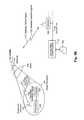
- FIG. 1Ais a schematic representation of an embodiment of a satellite communication system.
- FIG. 1Bis a schematic representation of the satellite communication system of FIG. 1A illustrating a single subscriber.
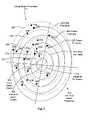
- FIG. 2is a schematic illustration of a satellite beam that is projected onto the earth's surface.
- FIG. 3is a schematic illustration of a satellite beam that is projected on the earth's surface at an incorrect location.
- FIG. 1Ais a schematic illustration of one embodiment of a satellite communication system.
- the satellite communication systemis a bidirectional system such as that used by WildBlue Communications Inc., located at 5970 Greenwood Plaza Blvd., Suite 300, Greenwood Village, Colo. 80111, that delivers and receives Internet data.
- satellite 102has a series of antennas that project beams 108 over the USA and receive signals from subscribers located within the beam projections 110 which cover most of the area of the USA.
- the antennas on the satellite 102are mounted on several different antenna arrays (pallets) which can be adjusted to be directed to different portions of the earth's surface. Some systems allow individual adjustment of antennas.
- the antenna arrays mounted on the satellite 102both send and receive data so that data can be transmitted downstream to subscribers on the ground and transmitters disposed at the subscriber location can transmit data upstream to the satellite 102 .
- Gateway 104uses antenna 106 to transmit gateway uplink signals 130 to the satellite 102 via the gateway antenna 106 .
- the gateway uplink signalis referred to as a downstream signal since it is sent downstream from the central office control system to the subscriber.
- gateway 104receives gateway downlink signals 132 from satellite 102 , which is an upstream signal.
- the embodiment illustrated in FIG. 1Amay have six gateways at six different locations.
- a high speed, wideband ground connection 116is provided between the central office control system 112 and the gateways, such as gateway 104 .
- Central office control system 112operates and controls the satellite communication system 100 , illustrated in FIG. 1A , and is connected to the Internet 114 .
- FIG. 1Billustrates a single beam 118 , of the plurality of beams 108 ( FIG. 1A ), and a single subscriber located within the beam projection 134 of beam 118 .
- the subscriberhas a subscriber antenna 124 that is connected to a subscriber transceiver 126 , which is connected to modem 127 .
- Modem 127is connected, in turn, to the subscriber computer 128 .
- Transceiver 126receives and transmits signals via subscriber antenna 124 .
- Modem 127processes data and controls the operation of transceiver 126 .
- the subscriber computer 128transmits and receives signals to and from modem 127 .
- Transceiver 126transmits the subscriber transmitted signal 122 (upstream signal) to the satellite 102 at 30 GHz. Similarly, transceiver 126 receives the subscriber received signal 120 (downstream signal) from the satellite 102 at 20 GHz. Beam 118 creates a beam projection 134 on the surface of the earth as a result of the focused antenna 103 , which is one of a number of focused antennas mounted on the satellite 102 that create beam 108 and beam projections 110 ( FIG. 1A ), including beam projection 134 . Antenna 103 is capable of transmitting the subscriber received signal 120 from the satellite 102 and receiving the subscriber transmitted signal 122 .
- signalsare transmitted between the satellite 102 and the gateway 104 , as explained above.
- Signals from the central office control system 112are transmitted over ground link 116 to the gateway 104 and transmitted as a gateway uplink signal 130 to satellite 102 .
- subscriber transmitted signals 122are received by the satellite 102 and transmitted to the gateway 104 as a gateway downlink signal 132 .
- the satellite 102also includes antennas that are directed specifically at the gateways. For example, a separate antenna is used to transmit the gateway downlink signal 132 to gateway 104 and receive the gateway uplink signal 130 from gateway 104 .
- the gateway 104includes a satellite modem termination system 133 that obtains data from the subscriber modem 127 every two seconds.
- the satellite modem termination system 133disposed in the gateways, sends data at periodic intervals, i.e., 15-minute increments, to the central office control system 112 where the data is processed.
- This dataincludes the signal power of the subscriber received signal 120 at the subscriber modem 127 , as well as the signal-to-noise ratio of the subscriber received signal 120 .
- both the power level and the signal-to-noise ratio of the subscriber received signal 120is encoded in the subscriber transmitted signal 122 and sent back to the satellite modem termination system 133 .
- the satellite modem termination 133 systemalso keeps track of the status of each of the modems 127 at the subscriber locations.
- the central office control system 112is linked to the Internet 114 to transmit and receive Internet data to and from the subscribers.
- the gateway uplink signal 130that is transmitted to the satellite 102 , is transmitted to the subscriber as a subscriber received signal 120 via beam 118 .
- the transceiverdetects the signal strength and signal-to-noise ratio of the subscriber received signal 120 .
- This datais encoded and attached to the subscriber transmitted signal 122 and sent by the satellite 102 via gateway downlink signal 132 which is received by the central office control system. This data indicates the signal strength and signal-to-noise ratio of the subscriber received signal 120 .
- the signal strength and signal-to-noise ratio of the subscriber received signal 120provides valuable information regarding the manner in which the antenna on the satellite 102 is pointed to create the beam 118 , as explained in more detail below.
- the central office control systemmaintains a record of the signal strength of the subscriber received signal 120 that is periodically updated.
- FIG. 2is a schematic illustration of a beam projection 200 which may comprise one of the beam projections 110 illustrated in FIG. 1A .
- the beam projection 200has a beam center 202 .
- the perimeters 204 - 212are oval in shape because of the projection of the beam on the earth's surface and the location of the stationary satellite 102 .
- the signal strength of the beamdecreases in a manner that is related to the distance from the beam center 202 .
- the roll off of signal strengthis substantially parabolic.
- Subscribers at subscriber cell locations 214 - 252provide encoded signal strength and signal-to-noise ratio signals, described above, to the central office control system 112 .
- the beam projection 200illustrates the various perimeters that result in a predetermined amount of attenuation or degradation in signal strength.
- perimeter 204indicates the attenuation of ⁇ 4 dB in signal strength under normal conditions without interference from adjacent signals.
- subscribers within cells 240 - 252on a clear day, and properly focused and properly aligned antenna without interference, would provide an encoded signal to the central office indicating that the signal strength was attenuated by approximately ⁇ 4 dB from the signal strength at the beam center 202 between perimeter 204 and perimeter 206 .
- the subscriber transmitted signal 122also encodes the signal-to-noise ratio data of the subscriber received signal 120 .
- the signal-to-noise ratio signalis a more reliable metric for determining misalignment of a beam.
- the signal-to-noise ratio signalprovides higher resolution than signal strength because of the interference problems with adjacent beams. In this manner, the signal-to-noise ratio is more accurate than the signal strength signal when interference is present.
- signal strengthmay be a better metric for determining proper placement of the beam.
- either the signal strength data or the signal-to-noise ratio data, that are encoded in the return, upstream signal from the subscribercan be used to determine proper alignment of the beam.
- This encoded datai.e., the encoded signal strength and signal-to-noise ratio signals, that are encoded and transmitted upstream to the central office control system 112 , are processed and color encoded at the central office control system 112 so that they can be displayed at the central office control system 112 to identify the actual location of the beam center or the edges of the beams.
- signal strength data from cells 232 - 238can be expected to be color-coded as yellow since these cells indicate an attenuation of approximately ⁇ 3 dB, under normal conditions.
- Cells 222 - 230under normal conditions, will show attenuation between ⁇ 1 dB and ⁇ 2 dB. These cells can be expected to be displayed as a green response since they fall within the green perimeter 208 .
- Cells 214 , 216 , 218under normal conditions, show an attenuation of up to ⁇ 1 dB, and as such can be expected to be color-coded as blue since they fall within the blue perimeter 210 .
- Subscriber responses from cell 220are sufficiently close to beam center 202 to show attenuation of less than ⁇ 1 dB and can be expected to be color-coded as magenta since they fall within the magenta perimeter 212 .
- the signal-to-noise ratio signalscan also be color encoded to display thematic mapping. For example, a similar encoding scheme may be used based upon different levels of the signal-to-noise ratio to provide a visual display of the signal-to-noise ratio signals from each of the cells 214 - 252 .
- the cells 214 - 252 that are illustrated in FIG. 2are representative cells in which one or more subscribers are located and provide a response for the geographical area of that cell.
- the cells illustrated in FIG. 2are schematic representations of the cells in which subscribers provide data. In most locations throughout the USA, most of the cells in the grid of cells that encompass the beam projection 200 are populated with at least one subscriber so that many more cells than that shown in FIG. 2 provide data to the central office control system that color codes and displays the data. For example, the system operated by WildBlue Communications, Inc. has over 300,000 subscribers spread throughout the USA.
- the cells 214 - 252are color-coded and there are many of these cells that are populated by subscribers, an accurate depiction of the beam projection 200 can be easily discerned from the displayed color-coded thematic mapping data. This information can be used to ensure that the beam projection 200 is aligned with the proper beam center 202 and that the antenna 103 ( FIG. 1B ) is properly aligned.
- FIG. 3illustrates a super-position of the intended beam projection 300 (solid lines) with actual beam projection 301 (dotted lines), as determined by the color-coded data from cells 214 - 252 .
- the intended beam projection perimeters 204 - 212solid lines
- the actual beam projection perimeters 304 - 312dotted lines
- the intended beam center 202is displaced from the actual beam center 314 .
- the actual beam center 314 and each of the actual perimeters 304 - 312are discernible from the color-coded responses from each of the cells 214 - 252 .
- a response from cell 234would appear as yellow rather than red since element 234 is inside the yellow perimeter 306 for the actual beam projection.
- element 234would normally appear as red since it falls within the red perimeter 204 .
- the actual datawould show element 234 as yellow, indicating that the actual beam projection 301 differs from the intended beam projection 300 .
- responses from cells 222 , 224 , 226would appear as green responses in the display of the actual data, whereas under the intended beam projection they would appear as yellow responses.
- cells 214 , 216 , 218should appear as green responses. However, cells 214 , 216 , 218 would appear in the displayed data as blue responses, since they fall within the blue perimeter 310 . Again, most of the cells in the total grid of cells that fall within the geographical area of the beam projections, that are illustrated in FIG. 3 , are populated with subscribers so that there is a large amount of data that clearly shows that the actual beam projection, shown by perimeter 304 - 312 (dotted perimeters), is not aligned with the actual beam projection, that is illustrated as the solid perimeter lines 204 - 212 .
- the color encoded datais capable of graphically illustrating the misalignment of the actual beam projection 301 with the intended beam projection 300 .
- the position of the actual beam center 314 from the intended beam center 302can be determined.
- the antenna array on the satellitesuch as antenna 103 ( FIG. 1B )
- the antenna array on the satellitecan be moved to align the actual beam center 314 with the intended beam center 302 .
- Control signals from the central office control system 112are transmitted via the ground link 116 to the satellite control center (SCC).
- the satellite control centersends a control signal to the satellite 102 to adjust the alignment of the antennas in accordance with the distance and direction determined between the actual beam center 314 and the intended beam center 302 .
- the antennas on the satellite 102can be properly aligned to create beam projections 110 ( FIG. 1A ) in the proper locations on the earth's surface.
- automated methods of determining the beam centercan be utilized, such as pattern recognition techniques, including edge detection techniques. These processes are well known to those skilled in the art. This process can be performed by analyzing the displayed data or simply by analyzing the raw data without displaying that data. Again, this data can comprise either the signal strength data or the signal-to-noise ratio data, or a combination of both.
- pattern recognition techniquesdo not actually have to determine the beam center, but rather, can determine the offset using other portions of the intended beam projection 300 and the actual beam projection 301 .
- both the antenna systems and the satellite itselfcan be aligned by iteratively moving the antennas and/or satellite and viewing the graphical representations of the displayed data until the antenna and/or satellite is properly aligned. In this manner, computational techniques for determining displacement of the antennas and/or satellite, as well as correction signals to correct alignment of the antennas and/or satellite, are not required.
- both the signal strength data and the signal-to-noise ratio datacan be used for aligning the antennas on the satellite to ensure that the beam projections 110 , that are illustrated in FIG. 1A , are properly aligned on the ground.
- this datacan also be used to properly align the satellite with respect to the earth's surface.
- a beacon siteis used in the Arctic that receives beacon signals from the satellite and provides steering and alignment signals to the satellite so that the satellite beacon remains pointed at the beacon site. The beacon site is expensive to build and operate.
- Both the signal strength signals and the signal-to-noise ratio signalscan be used to properly maintain the orientation of the satellite so that the satellite antennas are properly aligned on the ground.
- both the signal strength data and the signal-to-noise ratio datacan be used for both aligning antennas and for aligning the satellite.
Landscapes
- Engineering & Computer Science (AREA)
- Signal Processing (AREA)
- Computer Networks & Wireless Communication (AREA)
- Radio Relay Systems (AREA)
Abstract
Description
Claims (38)
Priority Applications (2)
| Application Number | Priority Date | Filing Date | Title |
|---|---|---|---|
| US12/544,130US8538328B2 (en) | 2008-09-11 | 2009-08-19 | Antenna and satellite alignment using beam projections |
| FR0956229AFR2935853A1 (en) | 2008-09-11 | 2009-09-11 | ANTENNA AND SATELLITE ALIGNMENT USING BEAM PROJECTIONS |
Applications Claiming Priority (2)
| Application Number | Priority Date | Filing Date | Title |
|---|---|---|---|
| US9597908P | 2008-09-11 | 2008-09-11 | |
| US12/544,130US8538328B2 (en) | 2008-09-11 | 2009-08-19 | Antenna and satellite alignment using beam projections |
Publications (2)
| Publication Number | Publication Date |
|---|---|
| US20100062706A1 US20100062706A1 (en) | 2010-03-11 |
| US8538328B2true US8538328B2 (en) | 2013-09-17 |
Family
ID=41728500
Family Applications (1)
| Application Number | Title | Priority Date | Filing Date |
|---|---|---|---|
| US12/544,130Active2030-12-10US8538328B2 (en) | 2008-09-11 | 2009-08-19 | Antenna and satellite alignment using beam projections |
Country Status (2)
| Country | Link |
|---|---|
| US (1) | US8538328B2 (en) |
| FR (1) | FR2935853A1 (en) |
Cited By (2)
| Publication number | Priority date | Publication date | Assignee | Title |
|---|---|---|---|---|
| US9091763B2 (en) | 2008-08-26 | 2015-07-28 | Viasat, Inc. | Weather detection using satellite communication signals |
| US9130889B2 (en) | 2009-09-04 | 2015-09-08 | Viasat, Inc. | Distributed cache—adaptive multicast architecture for bandwidth reduction |
Families Citing this family (11)
| Publication number | Priority date | Publication date | Assignee | Title |
|---|---|---|---|---|
| US7773942B2 (en) | 2006-08-29 | 2010-08-10 | Wildblue Communications, Inc. | Redundant communication path for satellite communication data |
| US8879982B2 (en)* | 2010-10-26 | 2014-11-04 | Emc Satcom Technologies, Llc | Automatic uplink power control in interference cancellation based spectral reuse |
| US10382977B2 (en) | 2014-12-09 | 2019-08-13 | Hughes Network Systems, Llc | Apparatus and method for monitoring operations in a satellite communication system |
| GB2541370A (en)* | 2015-07-27 | 2017-02-22 | Avanti Communications Group Plc | Satellite beam monitoring |
| US10361771B2 (en)* | 2016-01-22 | 2019-07-23 | Viasat, Inc. | Determining an attenuation environment of a satellite communication terminal |
| US9608716B1 (en) | 2016-04-06 | 2017-03-28 | Space Systems/Loral, Llc | Satellite transmit antenna ground-based pointing |
| US12250064B2 (en) | 2017-03-02 | 2025-03-11 | Lynk Global, Inc. | Method and apparatus for handling communications between spacecraft operating in an orbital environment and terrestrial telecommunications devices that use terrestrial base station communications |
| US10084535B1 (en) | 2017-04-26 | 2018-09-25 | UbiquitiLink, Inc. | Method and apparatus for handling communications between spacecraft operating in an orbital environment and terrestrial telecommunications devices that use terrestrial base station communications |
| US11863250B2 (en)* | 2021-01-06 | 2024-01-02 | Lynk Global, Inc. | Satellite communication system transmitting navigation signals using a wide beam and data signals using a directive beam |
| WO2022176893A1 (en)* | 2021-02-19 | 2022-08-25 | 三菱電機株式会社 | Method for forming integrated satellite constellation, integrated data library, and integrated satellite constellation |
| CN116165687B (en)* | 2023-03-27 | 2024-02-20 | 福建金石电子有限公司 | Beidou satellite based time-varying mode GPS method and device |
Citations (54)
| Publication number | Priority date | Publication date | Assignee | Title |
|---|---|---|---|---|
| GB1223163A (en) | 1967-06-24 | 1971-02-24 | Nippon Telegraph & Telephone | Improvements in or relating to satellite communication systems |
| US4041397A (en) | 1976-04-28 | 1977-08-09 | The United States Of America As Represented By The Secretary Of The Navy | Satellite up link diversity switch |
| US4287598A (en) | 1979-12-17 | 1981-09-01 | Bell Telephone Laboratories, Incorporated | Cooperating arrangement for diversity stations |
| US4599619A (en)* | 1982-07-13 | 1986-07-08 | Rca Corporation | Satellite dual antenna pointing system |
| US4630058A (en)* | 1982-02-26 | 1986-12-16 | Rca Corporation | Satellite communication system |
| US4858229A (en) | 1986-08-14 | 1989-08-15 | Hughes Aircraft Company | Filter interconnection matrix |
| US4910792A (en) | 1986-08-14 | 1990-03-20 | Kokusai Denshin Denwa Co., Ltd. | Up-link power control in satellite communications system |
| US5408237A (en)* | 1991-11-08 | 1995-04-18 | Teledesic Corporation | Earth-fixed cell beam management for satellite communication system |
| US5465410A (en) | 1994-11-22 | 1995-11-07 | Motorola, Inc. | Method and apparatus for automatic frequency and bandwidth control |
| US5550550A (en) | 1995-08-04 | 1996-08-27 | Das; Satyendranath | High efficiency satellite multibeam equally loaded transmitters |
| EP0762637A2 (en) | 1995-08-28 | 1997-03-12 | Nec Corporation | Variable output amplifier |
| EP0837569A2 (en) | 1996-10-21 | 1998-04-22 | Globalstar L.P. | Multiple satellite fade attenuation control system |
| US5839050A (en) | 1995-02-08 | 1998-11-17 | Actual Radio Measurement | System for determining radio listenership |
| WO1999018678A1 (en) | 1997-10-06 | 1999-04-15 | Hughes Electronics Corporation | System and method for enhanced satellite payload power utilization |
| EP0911992A2 (en) | 1997-10-17 | 1999-04-28 | Hughes Electronics Corporation | Dynamic interference optimization method for satellites transmitting multiple beams with common frequencies |
| US5987233A (en) | 1998-03-16 | 1999-11-16 | Skycache Inc. | Comprehensive global information network broadcasting system and implementation thereof |
| US5991622A (en) | 1997-08-22 | 1999-11-23 | Ericsson Inc. | Method and apparatus for automatic channel measurements |
| US5991306A (en) | 1996-08-26 | 1999-11-23 | Microsoft Corporation | Pull based, intelligent caching system and method for delivering data over a network |
| WO1999063711A1 (en) | 1998-06-02 | 1999-12-09 | Ivanov, Iliya Borisovitch | Method for accessing the resources of the world wide web |
| US6047171A (en) | 1998-01-08 | 2000-04-04 | Ericsson Inc. | Method and apparatus for combating adjacent channel interference using multiple IF filters |
| US6052084A (en)* | 1996-05-29 | 2000-04-18 | Toyota Jidosha Kabushiki Kaisha | Vehicle-mounted satellite signal receiving system |
| EP0998063A2 (en) | 1998-10-30 | 2000-05-03 | TRW Inc. | Method for enhancing the performance of a satellite communications system using multibeam antennas |
| WO2000046682A1 (en) | 1999-02-04 | 2000-08-10 | Cyberstar, L.P. | Internet service provider refresh via satellite |
| US6169513B1 (en) | 1998-02-25 | 2001-01-02 | Space Systems/Loral, Inc. | Thinned multiple beam phased array antenna |
| US6288670B1 (en)* | 1999-12-23 | 2001-09-11 | Hughes Electronics Corporation | Combined roll-yaw spacecraft steering method for low earth orbit target trajectory compensation |
| US20010052015A1 (en) | 1998-06-24 | 2001-12-13 | Chueng-Hsien Lin | Push-pull sevices for the internet |
| US20020006116A1 (en) | 2000-05-04 | 2002-01-17 | Reed Burkhart | Distributed content management and open broadcast system using satellites and the internet |
| US20020073167A1 (en) | 1999-12-08 | 2002-06-13 | Powell Kyle E. | Internet content delivery acceleration system employing a hybrid content selection scheme |
| US6442598B1 (en) | 1997-10-27 | 2002-08-27 | Microsoft Corporation | System and method for delivering web content over a broadcast medium |
| US20020143984A1 (en) | 2001-03-19 | 2002-10-03 | The Aerospace Corporation | Cooperative adaptive web caching routing and forwarding web content data broadcasting method |
| US6546488B2 (en) | 1997-09-22 | 2003-04-08 | Hughes Electronics Corporation | Broadcast delivery of information to a personal computer for local storage and access |
| US6601090B1 (en) | 1999-06-25 | 2003-07-29 | Nortel Networks Limited | System and method for servicing internet object accessess from a coupled intranet |
| US6618751B1 (en) | 1999-08-20 | 2003-09-09 | International Business Machines Corporation | Systems and methods for publishing data with expiration times |
| US6658463B1 (en) | 1999-06-10 | 2003-12-02 | Hughes Electronics Corporation | Satellite multicast performance enhancing multicast HTTP proxy system and method |
| WO2004002016A2 (en) | 2002-06-25 | 2003-12-31 | Qualcomm, Incorporated | Reducing service outages in a multibeam satellite system |
| US6678791B1 (en) | 2001-08-04 | 2004-01-13 | Sun Microsystems, Inc. | System and method for session-aware caching |
| US20040037193A1 (en)* | 2000-07-12 | 2004-02-26 | Palle Andersen | Method for improved reading of a digital data disc |
| US6763006B1 (en) | 1999-09-22 | 2004-07-13 | Sola Communications, Inc. | Method and apparatus for controlling uplink transmission power within a satellite communication system |
| US20040203444A1 (en) | 2003-01-22 | 2004-10-14 | Keith Jarett | Closed-loop pointing system for wireless communication with spot beams and wide-area beams |
| US20040203725A1 (en)* | 2002-04-01 | 2004-10-14 | Shlomo Lahav | Classification of cellular network drive test results |
| US20040224633A1 (en) | 2003-05-05 | 2004-11-11 | Agence Spatiale Europeenne | Multi-beam satellite communications payload with flexible power allocation |
| US6825806B2 (en)* | 2002-06-03 | 2004-11-30 | The Boeing Company | Satellite methods and structures for improved antenna pointing and wide field-of-view attitude acquisition |
| US20040242152A1 (en)* | 2003-05-30 | 2004-12-02 | The Boeing Company | Wireless communication system with split spot beam payload |
| WO2005067367A2 (en) | 2004-01-16 | 2005-07-28 | Inmarsat Ltd. | Satellite monitoring |
| US6947440B2 (en) | 2000-02-15 | 2005-09-20 | Gilat Satellite Networks, Ltd. | System and method for internet page acceleration including multicast transmissions |
| US7039683B1 (en) | 2000-09-25 | 2006-05-02 | America Online, Inc. | Electronic information caching |
| US20070037512A1 (en) | 2001-02-27 | 2007-02-15 | Godwin John P | Device and method to locally fill gaps in spotbeam satellite systems with frequency re-use |
| US7289062B2 (en)* | 2005-02-15 | 2007-10-30 | Wildblue Communications, Inc. | Method and device for accurately pointing a satellite earth station antenna |
| US7324782B1 (en)* | 2000-08-14 | 2008-01-29 | Lucent Technologies Inc. | Location based adaptive antenna scheme for wireless data applications |
| US7330151B1 (en)* | 2006-12-21 | 2008-02-12 | The Boeing Company | Alignment of an elliptical beam of an antenna |
| US20080056189A1 (en) | 2006-08-29 | 2008-03-06 | Wildblue Communications, Inc. | Network-Access Satellite Communication System |
| US7359395B2 (en)* | 2003-06-16 | 2008-04-15 | Packeteer, Inc. | Pre-fetch communication systems and methods |
| US7516236B2 (en) | 2001-12-21 | 2009-04-07 | Nokia Corporation | Method to improve perceived access speed to data network content using a multicast channel and local cache |
| US20110222589A1 (en)* | 2010-03-12 | 2011-09-15 | Inmarsat Global Limited | Satellite Beam Monitoring |
- 2009
- 2009-08-19USUS12/544,130patent/US8538328B2/enactiveActive
- 2009-09-11FRFR0956229Apatent/FR2935853A1/enactivePending
Patent Citations (60)
| Publication number | Priority date | Publication date | Assignee | Title |
|---|---|---|---|---|
| GB1223163A (en) | 1967-06-24 | 1971-02-24 | Nippon Telegraph & Telephone | Improvements in or relating to satellite communication systems |
| US4041397A (en) | 1976-04-28 | 1977-08-09 | The United States Of America As Represented By The Secretary Of The Navy | Satellite up link diversity switch |
| US4287598A (en) | 1979-12-17 | 1981-09-01 | Bell Telephone Laboratories, Incorporated | Cooperating arrangement for diversity stations |
| US4630058A (en)* | 1982-02-26 | 1986-12-16 | Rca Corporation | Satellite communication system |
| US4599619A (en)* | 1982-07-13 | 1986-07-08 | Rca Corporation | Satellite dual antenna pointing system |
| US4858229A (en) | 1986-08-14 | 1989-08-15 | Hughes Aircraft Company | Filter interconnection matrix |
| US4910792A (en) | 1986-08-14 | 1990-03-20 | Kokusai Denshin Denwa Co., Ltd. | Up-link power control in satellite communications system |
| US5408237A (en)* | 1991-11-08 | 1995-04-18 | Teledesic Corporation | Earth-fixed cell beam management for satellite communication system |
| US5465410A (en) | 1994-11-22 | 1995-11-07 | Motorola, Inc. | Method and apparatus for automatic frequency and bandwidth control |
| US5839050A (en) | 1995-02-08 | 1998-11-17 | Actual Radio Measurement | System for determining radio listenership |
| US5550550A (en) | 1995-08-04 | 1996-08-27 | Das; Satyendranath | High efficiency satellite multibeam equally loaded transmitters |
| EP0762637A2 (en) | 1995-08-28 | 1997-03-12 | Nec Corporation | Variable output amplifier |
| US6052084A (en)* | 1996-05-29 | 2000-04-18 | Toyota Jidosha Kabushiki Kaisha | Vehicle-mounted satellite signal receiving system |
| US5991306A (en) | 1996-08-26 | 1999-11-23 | Microsoft Corporation | Pull based, intelligent caching system and method for delivering data over a network |
| EP0837569A2 (en) | 1996-10-21 | 1998-04-22 | Globalstar L.P. | Multiple satellite fade attenuation control system |
| US5991622A (en) | 1997-08-22 | 1999-11-23 | Ericsson Inc. | Method and apparatus for automatic channel measurements |
| US6546488B2 (en) | 1997-09-22 | 2003-04-08 | Hughes Electronics Corporation | Broadcast delivery of information to a personal computer for local storage and access |
| WO1999018678A1 (en) | 1997-10-06 | 1999-04-15 | Hughes Electronics Corporation | System and method for enhanced satellite payload power utilization |
| EP0911992A2 (en) | 1997-10-17 | 1999-04-28 | Hughes Electronics Corporation | Dynamic interference optimization method for satellites transmitting multiple beams with common frequencies |
| US6272679B1 (en)* | 1997-10-17 | 2001-08-07 | Hughes Electronics Corporation | Dynamic interference optimization method for satellites transmitting multiple beams with common frequencies |
| US6442598B1 (en) | 1997-10-27 | 2002-08-27 | Microsoft Corporation | System and method for delivering web content over a broadcast medium |
| US6047171A (en) | 1998-01-08 | 2000-04-04 | Ericsson Inc. | Method and apparatus for combating adjacent channel interference using multiple IF filters |
| US6169513B1 (en) | 1998-02-25 | 2001-01-02 | Space Systems/Loral, Inc. | Thinned multiple beam phased array antenna |
| US6434609B1 (en) | 1998-03-16 | 2002-08-13 | Cidera, Inc. | Comprehensive global information network broadcasting system and methods of distributing information |
| US5987233A (en) | 1998-03-16 | 1999-11-16 | Skycache Inc. | Comprehensive global information network broadcasting system and implementation thereof |
| WO1999063711A1 (en) | 1998-06-02 | 1999-12-09 | Ivanov, Iliya Borisovitch | Method for accessing the resources of the world wide web |
| US20010052015A1 (en) | 1998-06-24 | 2001-12-13 | Chueng-Hsien Lin | Push-pull sevices for the internet |
| US6150977A (en)* | 1998-10-30 | 2000-11-21 | Trw Inc. | Method for enhancing the performance of a satellite communications system using multibeam antennas |
| EP0998063A2 (en) | 1998-10-30 | 2000-05-03 | TRW Inc. | Method for enhancing the performance of a satellite communications system using multibeam antennas |
| WO2000046682A1 (en) | 1999-02-04 | 2000-08-10 | Cyberstar, L.P. | Internet service provider refresh via satellite |
| US6658463B1 (en) | 1999-06-10 | 2003-12-02 | Hughes Electronics Corporation | Satellite multicast performance enhancing multicast HTTP proxy system and method |
| US6601090B1 (en) | 1999-06-25 | 2003-07-29 | Nortel Networks Limited | System and method for servicing internet object accessess from a coupled intranet |
| US6618751B1 (en) | 1999-08-20 | 2003-09-09 | International Business Machines Corporation | Systems and methods for publishing data with expiration times |
| US6763006B1 (en) | 1999-09-22 | 2004-07-13 | Sola Communications, Inc. | Method and apparatus for controlling uplink transmission power within a satellite communication system |
| US20020073167A1 (en) | 1999-12-08 | 2002-06-13 | Powell Kyle E. | Internet content delivery acceleration system employing a hybrid content selection scheme |
| US6288670B1 (en)* | 1999-12-23 | 2001-09-11 | Hughes Electronics Corporation | Combined roll-yaw spacecraft steering method for low earth orbit target trajectory compensation |
| US6947440B2 (en) | 2000-02-15 | 2005-09-20 | Gilat Satellite Networks, Ltd. | System and method for internet page acceleration including multicast transmissions |
| US20020006116A1 (en) | 2000-05-04 | 2002-01-17 | Reed Burkhart | Distributed content management and open broadcast system using satellites and the internet |
| US20040037193A1 (en)* | 2000-07-12 | 2004-02-26 | Palle Andersen | Method for improved reading of a digital data disc |
| US7324782B1 (en)* | 2000-08-14 | 2008-01-29 | Lucent Technologies Inc. | Location based adaptive antenna scheme for wireless data applications |
| US7039683B1 (en) | 2000-09-25 | 2006-05-02 | America Online, Inc. | Electronic information caching |
| US20070037512A1 (en) | 2001-02-27 | 2007-02-15 | Godwin John P | Device and method to locally fill gaps in spotbeam satellite systems with frequency re-use |
| US20020143984A1 (en) | 2001-03-19 | 2002-10-03 | The Aerospace Corporation | Cooperative adaptive web caching routing and forwarding web content data broadcasting method |
| US6678791B1 (en) | 2001-08-04 | 2004-01-13 | Sun Microsystems, Inc. | System and method for session-aware caching |
| US7516236B2 (en) | 2001-12-21 | 2009-04-07 | Nokia Corporation | Method to improve perceived access speed to data network content using a multicast channel and local cache |
| US20040203725A1 (en)* | 2002-04-01 | 2004-10-14 | Shlomo Lahav | Classification of cellular network drive test results |
| US6825806B2 (en)* | 2002-06-03 | 2004-11-30 | The Boeing Company | Satellite methods and structures for improved antenna pointing and wide field-of-view attitude acquisition |
| WO2004002016A2 (en) | 2002-06-25 | 2003-12-31 | Qualcomm, Incorporated | Reducing service outages in a multibeam satellite system |
| US20040203444A1 (en) | 2003-01-22 | 2004-10-14 | Keith Jarett | Closed-loop pointing system for wireless communication with spot beams and wide-area beams |
| US7130578B2 (en)* | 2003-01-22 | 2006-10-31 | The Boeing Company | Closed-loop pointing system for wireless communication with spot beams and wide-area beams |
| US20040224633A1 (en) | 2003-05-05 | 2004-11-11 | Agence Spatiale Europeenne | Multi-beam satellite communications payload with flexible power allocation |
| US20040242152A1 (en)* | 2003-05-30 | 2004-12-02 | The Boeing Company | Wireless communication system with split spot beam payload |
| US7359395B2 (en)* | 2003-06-16 | 2008-04-15 | Packeteer, Inc. | Pre-fetch communication systems and methods |
| WO2005067367A2 (en) | 2004-01-16 | 2005-07-28 | Inmarsat Ltd. | Satellite monitoring |
| US7289062B2 (en)* | 2005-02-15 | 2007-10-30 | Wildblue Communications, Inc. | Method and device for accurately pointing a satellite earth station antenna |
| US20080056189A1 (en) | 2006-08-29 | 2008-03-06 | Wildblue Communications, Inc. | Network-Access Satellite Communication System |
| WO2008027974A2 (en) | 2006-08-29 | 2008-03-06 | Wildblue Communications, Inc. | Network-access satellite communication system |
| US20080056176A1 (en) | 2006-08-29 | 2008-03-06 | Wildblue Communications, Inc. | Network-access satellite communication system |
| US7330151B1 (en)* | 2006-12-21 | 2008-02-12 | The Boeing Company | Alignment of an elliptical beam of an antenna |
| US20110222589A1 (en)* | 2010-03-12 | 2011-09-15 | Inmarsat Global Limited | Satellite Beam Monitoring |
Non-Patent Citations (18)
| Title |
|---|
| "Digital Video Broadcasting (DVB); Second Generation Framing Structure, Channel coding and Modulation Systems for Broadcasting, Interactive Services, News Gathering and other Broadband Satellite Applications", (ETSI EN 302 307) version 1.1.2, Jun. 2006. Available from www.etsi.org. Downloaded on Oct. 9, 2008. |
| Data Over Cable Service Interface Specifications (DOCSIS 3.0): Physical Layer Specification, May 22, 2008. Available from www.cablemodem.com. Downloaded on Oct. 9, 2008. Cable Television Laboratories, Inc. Copyright 2006-2008. CM-SP-PHYv3.0-107-080522. |
| Digital Video Broadcasting (DVB);Second generation framing structure, channel coding and modulation systems for Broadcasting, Interactive Services, News Gathering and other broadband satellite applications, (draft ETSI EN 302 307) version 1.1.1, Jun. 2004. Available from www.etsi.org. Downloaded on Oct. 9, 2008. |
| Inpi, FR App. No. 0956229, Written Opinion and Search Report dated Jan. 16, 2013, 12 pgs. |
| International Search Report and Written Opinion of the International Searching Authority; International Application No. PCT US2007/077124; filed Jul. 22, 2008. |
| Patent Abstracts of Japan; vol. 012, No. 452 (E-687), Nov. 28, 1988, and JP 63 179629 A (Nippon Telegr & Teleph Corp), Jul. 23, 1988 (see abstract). |
| Patent Abstracts of Japan; vol. 012, No. 461 (E-689), Dec. 5, 1988, and JP 63 185129 A (NEC Corp), Jul. 30, 1988 (see abstract). |
| U.S. Appl. No. 11/847,006, filed Aug. 29, 2007. |
| U.S. Appl. No. 11/847,064, filed Aug. 29, 2007. |
| U.S. Appl. No. 11/847,084, filed Aug. 29, 2007. |
| U.S. Appl. No. 11/847,102, filed Aug. 29, 2007. |
| U.S. Appl. No. 11/847,121, filed Aug. 29, 2007. |
| U.S. Appl. No. 12/265,618, filed Nov. 5, 2008. |
| U.S. Appl. No. 12/544,121, filed Aug. 19, 2009. |
| U.S. Appl. No. 60/840,809, filed Aug. 29, 2006. |
| U.S. Appl. No. 61/091,984, filed Aug. 26, 2008. |
| U.S. Appl. No. 61/095,979, filed Sep. 11, 2008. |
| U.S. Appl. No. 61/100,206, filed Sep. 25, 2008. |
Cited By (2)
| Publication number | Priority date | Publication date | Assignee | Title |
|---|---|---|---|---|
| US9091763B2 (en) | 2008-08-26 | 2015-07-28 | Viasat, Inc. | Weather detection using satellite communication signals |
| US9130889B2 (en) | 2009-09-04 | 2015-09-08 | Viasat, Inc. | Distributed cache—adaptive multicast architecture for bandwidth reduction |
Also Published As
| Publication number | Publication date |
|---|---|
| US20100062706A1 (en) | 2010-03-11 |
| FR2935853A1 (en) | 2010-03-12 |
Similar Documents
| Publication | Publication Date | Title |
|---|---|---|
| US8538328B2 (en) | Antenna and satellite alignment using beam projections | |
| US8730086B2 (en) | Weather detection using satellite communication signals | |
| US11686852B2 (en) | Systems and methods for interference detection in shared spectrum channels | |
| US10630382B2 (en) | Systems and methods for beacon detection infrastructures | |
| US10656281B2 (en) | Systems and methods for interference detection in shared spectrum channels | |
| US7501982B2 (en) | Antenna alignment method | |
| CN112193439B (en) | Satellite-ground integrated high-precision satellite multi-beam calibration method | |
| US10957975B2 (en) | System and method of adjusting antenna beam on antenna tower | |
| US6690917B2 (en) | System and method for automatic determination of azimuthal and elevation direction of directional antennas and calibration thereof | |
| US6417803B1 (en) | Beam alignment system and method for an antenna | |
| US5946603A (en) | Method and apparatus to respond to a blockage environment in a communication system | |
| EP2158639B1 (en) | System and method for remote antenna positioning data acquisition | |
| CA3003801C (en) | Method for maintaining signal-to-noise ratio at a user terminal in a satellite system | |
| US20060064726A1 (en) | Method of using feedback from consumer terminals to adaptively control a satellite system | |
| EP2951605B1 (en) | A method for alignment of multi-beam antennas in a non line-of-sight scenario | |
| CN107637113A (en) | The Method of Avoiding the Interference of Synchronous Satellites by Returning Orbiting Satellite Constellation and Ground Station System | |
| US6321065B1 (en) | Performance enhancement of open-loop power control for satellite communication systems | |
| US10756447B2 (en) | Communication terminal device applicable to aerial vehicle and mobile communication method using the same | |
| CN104994526A (en) | Method for measuring azimuth angle of mobile communication base station antenna | |
| US6476764B2 (en) | Post-installation monitoring method for a satellite terminal antenna | |
| CN114389650A (en) | Satellite-borne three-dimensional ADS-B multi-beam array antenna design method | |
| CN112118041B (en) | Earth station and access method and device thereof | |
| US6816114B1 (en) | System for polarization tilting and main beam steering of airship antenna using GPS | |
| FI129476B (en) | Antenna radiation pattern extraction using sparse field measurements | |
| WO2003094287A1 (en) | Beam alignment methods for an antenna |
Legal Events
| Date | Code | Title | Description |
|---|---|---|---|
| AS | Assignment | Owner name:WILDBLUE COMMUNICATIONS, INC.,COLORADO Free format text:ASSIGNMENT OF ASSIGNORS INTEREST;ASSIGNORS:MILLS, RAYMOND L.;MARTIN, REMBERTO L.;REEL/FRAME:023131/0187 Effective date:20090819 Owner name:WILDBLUE COMMUNICATIONS, INC., COLORADO Free format text:ASSIGNMENT OF ASSIGNORS INTEREST;ASSIGNORS:MILLS, RAYMOND L.;MARTIN, REMBERTO L.;REEL/FRAME:023131/0187 Effective date:20090819 | |
| AS | Assignment | Owner name:VIASAT, INC., CALIFORNIA Free format text:ASSIGNMENT OF ASSIGNORS INTEREST;ASSIGNOR:WILD BLUE COMMUNICATIONS, INC.;REEL/FRAME:025038/0028 Effective date:20100923 | |
| AS | Assignment | Owner name:UNION BANK, N.A., CALIFORNIA Free format text:SECURITY AGREEMENT;ASSIGNOR:VIASAT, INC.;REEL/FRAME:028184/0152 Effective date:20120509 | |
| FEPP | Fee payment procedure | Free format text:PAYER NUMBER DE-ASSIGNED (ORIGINAL EVENT CODE: RMPN); ENTITY STATUS OF PATENT OWNER: LARGE ENTITY Free format text:PAYOR NUMBER ASSIGNED (ORIGINAL EVENT CODE: ASPN); ENTITY STATUS OF PATENT OWNER: LARGE ENTITY | |
| STCF | Information on status: patent grant | Free format text:PATENTED CASE | |
| CC | Certificate of correction | ||
| FPAY | Fee payment | Year of fee payment:4 | |
| AS | Assignment | Owner name:WILMINGTON TRUST, NATIONAL ASSOCIATION, AS COLLATE Free format text:SECURITY INTEREST;ASSIGNOR:VIASAT, INC.;REEL/FRAME:048715/0589 Effective date:20190327 Owner name:WILMINGTON TRUST, NATIONAL ASSOCIATION, AS COLLATERAL TRUSTEE, MINNESOTA Free format text:SECURITY INTEREST;ASSIGNOR:VIASAT, INC.;REEL/FRAME:048715/0589 Effective date:20190327 | |
| MAFP | Maintenance fee payment | Free format text:PAYMENT OF MAINTENANCE FEE, 8TH YEAR, LARGE ENTITY (ORIGINAL EVENT CODE: M1552); ENTITY STATUS OF PATENT OWNER: LARGE ENTITY Year of fee payment:8 | |
| AS | Assignment | Owner name:BANK OF AMERICA, N.A., NORTH CAROLINA Free format text:SECURITY AGREEMENT;ASSIGNOR:VIASAT, INC.;REEL/FRAME:059332/0558 Effective date:20220304 | |
| AS | Assignment | Owner name:BANK OF AMERICA, N.A., AS AGENT, NORTH CAROLINA Free format text:SECURITY AGREEMENT;ASSIGNOR:VIASAT, INC.;REEL/FRAME:063822/0446 Effective date:20230530 | |
| MAFP | Maintenance fee payment | Free format text:PAYMENT OF MAINTENANCE FEE, 12TH YEAR, LARGE ENTITY (ORIGINAL EVENT CODE: M1553); ENTITY STATUS OF PATENT OWNER: LARGE ENTITY Year of fee payment:12 |