US8537522B2 - Electrolytic capacitor - Google Patents
Electrolytic capacitorDownload PDFInfo
- Publication number
- US8537522B2 US8537522B2US13/116,461US201113116461AUS8537522B2US 8537522 B2US8537522 B2US 8537522B2US 201113116461 AUS201113116461 AUS 201113116461AUS 8537522 B2US8537522 B2US 8537522B2
- Authority
- US
- United States
- Prior art keywords
- capacitor
- cover
- terminal
- electrolytic
- terminals
- Prior art date
- Legal status (The legal status is an assumption and is not a legal conclusion. Google has not performed a legal analysis and makes no representation as to the accuracy of the status listed.)
- Active
Links
Images


Classifications
- H—ELECTRICITY
- H01—ELECTRIC ELEMENTS
- H01G—CAPACITORS; CAPACITORS, RECTIFIERS, DETECTORS, SWITCHING DEVICES, LIGHT-SENSITIVE OR TEMPERATURE-SENSITIVE DEVICES OF THE ELECTROLYTIC TYPE
- H01G9/00—Electrolytic capacitors, rectifiers, detectors, switching devices, light-sensitive or temperature-sensitive devices; Processes of their manufacture
- H01G9/004—Details
- H01G9/08—Housing; Encapsulation
- H01G9/12—Vents or other means allowing expansion
- H—ELECTRICITY
- H01—ELECTRIC ELEMENTS
- H01G—CAPACITORS; CAPACITORS, RECTIFIERS, DETECTORS, SWITCHING DEVICES, LIGHT-SENSITIVE OR TEMPERATURE-SENSITIVE DEVICES OF THE ELECTROLYTIC TYPE
- H01G9/00—Electrolytic capacitors, rectifiers, detectors, switching devices, light-sensitive or temperature-sensitive devices; Processes of their manufacture
- H01G9/004—Details
- H01G9/008—Terminals
- H—ELECTRICITY
- H01—ELECTRIC ELEMENTS
- H01G—CAPACITORS; CAPACITORS, RECTIFIERS, DETECTORS, SWITCHING DEVICES, LIGHT-SENSITIVE OR TEMPERATURE-SENSITIVE DEVICES OF THE ELECTROLYTIC TYPE
- H01G9/00—Electrolytic capacitors, rectifiers, detectors, switching devices, light-sensitive or temperature-sensitive devices; Processes of their manufacture
- H01G9/004—Details
- H01G9/08—Housing; Encapsulation
- H01G9/10—Sealing, e.g. of lead-in wires
- H—ELECTRICITY
- H01—ELECTRIC ELEMENTS
- H01G—CAPACITORS; CAPACITORS, RECTIFIERS, DETECTORS, SWITCHING DEVICES, LIGHT-SENSITIVE OR TEMPERATURE-SENSITIVE DEVICES OF THE ELECTROLYTIC TYPE
- H01G9/00—Electrolytic capacitors, rectifiers, detectors, switching devices, light-sensitive or temperature-sensitive devices; Processes of their manufacture
- H01G9/145—Liquid electrolytic capacitors
- H—ELECTRICITY
- H01—ELECTRIC ELEMENTS
- H01G—CAPACITORS; CAPACITORS, RECTIFIERS, DETECTORS, SWITCHING DEVICES, LIGHT-SENSITIVE OR TEMPERATURE-SENSITIVE DEVICES OF THE ELECTROLYTIC TYPE
- H01G9/00—Electrolytic capacitors, rectifiers, detectors, switching devices, light-sensitive or temperature-sensitive devices; Processes of their manufacture
- H01G9/15—Solid electrolytic capacitors
- H01G9/151—Solid electrolytic capacitors with wound foil electrodes
Definitions
- This disclosurerelates to a capacitor. More specifically it relates to a capacitor with multiple capacitor sections selectively connectable to match the capacitance or capacitances of one or more capacitors being replaced.
- capacitorsare used in connection with the motors of air-conditioning systems.
- the systemsoften employ two capacitors, one used in association with a compressor motor and another smaller value capacitor for use in association with a fan motor.
- Air-conditioning systems of different BTU capacity, made by different manufacturers or being a different modelmay use capacitors having different values. These capacitors have a finite life and may fail, causing the system to become inoperative.
- a serviceman making a service callusually does not know in advance whether a replacement capacitor is necessary to repair an air-conditioning system, or what value capacitor or capacitors might be needed for the repair.
- the servicemancarries a large number of capacitors of different values in the service truck, but it is difficult and expensive to maintain such an inventory, especially because there can be a random need for several capacitors of the same value on the same day.
- the servicemanreturns to the shop or visit a supplier to pick up a replacement capacitor of the required value. This is inefficient as the travel time to pick up parts greatly extends the overall time necessary to complete a repair, and detrimental if there is a backlog of inoperative air-conditioning systems on a hot day.
- a similar situationmay occur is other applications such as refrigeration and heating systems, pumps, and manufacturing systems that utilize compressors.
- a servicemanmay carry the capacitor on a service call and, upon encountering one or more failed capacitors, the serviceman can utilize the capacitor to replace the failed capacitor or capacitors.
- the replacement capacitoris connectable to an electric circuit with selectable capacitance values.
- the capacitorprovides multiple capacitance values that may be connected in the field to replace the capacitance value or values of a failed capacitor or capacitors.
- an apparatuswhich includes an electrolytic capacitive element with multiple capacitor sections.
- the disclosurefeatures a system that provides a plurality of selectable capacitance values.
- the systemincludes a electrolytic capacitive element that has a plurality of capacitor sections. Each capacitor section has a capacitance value and a capacitor section terminal at a first end.
- the electrolytic capacitive elementhas a common element terminal at a second end.
- the systemalso includes a plurality of insulated capacitor section wires each connected at one end to a respective section terminal of one of the plurality of capacitor sections, and an insulated common conductor connected at one end to the common element terminal of the capacitor element.
- the systemalso includes a case having a side wall, a bottom wall and an open top.
- the electrolytic capacitive element and the insulated wires and insulated conductor connected theretoare received in the case with the common element terminal adjacent to and insulated from the bottom wall.
- the systemalso includes a pressure interrupter cover assembly that includes a deformable cover, a common cover terminal mounted to the deformable cover generally at the center of the cover, a plurality of capacitor section cover terminals mounted to the deformable cover at spaced apart positions generally surrounding the common cover terminal, and connections connecting the terminal post of the common cover terminal to the conductor extending from the common element terminal, and connections respectively connecting the plurality of capacitor section wires to a corresponding terminal post of the plurality of capacitor section cover terminals.
- the deformable coverhas a peripheral edge sealingly secured to an upper end of the case.
- the common cover terminalhas a contact extending upwardly from the cover and a terminal post extending downwardly from the cover to a distal end.
- Each capacitor section cover terminalhas at least two contacts extending upwardly from the cover and a terminal post extending downwardly from the cover to a distal end thereof.
- Selectable capacitance valuesare provided by connecting selected cover terminals to place the corresponding capacitor sections in one or more electric circuits and wherein failure of the electrolytic capacitive element causes the deformable cover to deform.
- the disclosurefeatures a system that provides a plurality of selectable capacitance values.
- the systemincludes an electrolytic capacitive element having a plurality of capacitors, a plurality of insulated capacitor wires each connected at one end to a respective capacitor terminal of the capacitors, and an insulated common conductor connected at one end to the common element terminal of the electrolytic capacitive element, a case having a side wall, a bottom wall and an open top, and a pressure interrupter cover assembly.
- Each capacitorhas a capacitance value and a capacitor terminal at a first end.
- the electrolytic capacitive elementhas a common element terminal at a second end.
- the electrolytic capacitive element, the insulated wires, and insulated conductorare received in the case with the common element terminal adjacent to and insulated from the bottom wall of the case.
- the pressure cover assemblyincludes a deformable cover, a common cover terminal mounted to the deformable cover generally at the center of the cover, a plurality of capacitor cover terminals mounted to the deformable cover at spaced apart positions generally surrounding the common cover terminal, and connections connecting the terminal post of the common cover terminal to the conductor extending from the common element terminal, and connections respectively connecting the plurality of capacitor wires to a corresponding terminal post of the plurality of capacitor cover terminals.
- the deformable coverhas a peripheral edge sealingly secured to an upper end of the case.
- the common cover terminalhas a contact extending upwardly from the cover and a terminal post extending downwardly from the cover to a distal end.
- Each capacitor cover terminalhas at least two contacts extending upwardly from the cover and a terminal post extending downwardly from the cover to a distal end thereof.
- the selectable capacitance valuesare provided by connecting selected cover terminals to place the corresponding capacitors in one or more electric circuits and wherein failure of the electrolytic capacitive element causes the deformable cover to deform.
- the disclosurefeatures a system that provides a plurality of selectable capacitance values.
- the systemincludes an electrolytic capacitive element having a plurality of capacitors, a plurality of insulated capacitor wires each connected at one end to a respective first capacitor terminal of one of the capacitors, and an insulated common conductor connected at one end to all of the second capacitor terminals of all capacitors, a case having a side wall, a bottom wall and an open top, a pressure interrupter cover assembly, and connections connecting the terminal post of the common cover terminal to the conductor extending from the second capacitor terminals, and connections respectively connecting the plurality of capacitor wires to a corresponding terminal post of the plurality of capacitor cover terminals.
- Each capacitorhas a capacitance value and a first capacitor terminal at a first end of each capacitor and a second capacitor terminal at a second end of each capacitor.
- the electrolytic capacitive element and the insulated wires and insulated conductor connected theretoare received in the case.
- the pressure interrupter cover assemblyincludes a deformable cover, a common cover terminal mounted to the deformable cover generally at the center of the cover, a plurality of capacitor cover terminals mounted to the deformable cover at spaced apart positions generally surrounding the common cover terminal, and connections connecting the terminal post of the common cover terminal to the conductor extending from the second capacitor terminals, and connections respectively connecting the plurality of capacitor wires to a corresponding terminal post of the plurality of capacitor cover terminals.
- the deformable coverhas a peripheral edge sealingly secured to an upper end of the case.
- the common cover terminalhas a contact extending upwardly from the cover and a terminal post extending downwardly from the cover to a distal end.
- Each capacitor cover terminalhaving at least two contacts extending upwardly from the cover and a terminal post extending downwardly from the cover to a distal end thereof.
- the selectable capacitance valuesare provided by connecting selected cover terminals to place the corresponding capacitors in one or more electric circuits and wherein failure of the electrolytic capacitive element causes the deformable cover to deform.
- the disclosurefeatures a system that provides a plurality of selectable capacitance values.
- the systemincludes an electrolytic capacitive element having a plurality of capacitors, a plurality of insulated capacitor wires each connected at one end to a respective first capacitor terminal of the capacitors, and an insulated common conductor connected at one end to all of the second capacitor terminals of all capacitors, a case having a cylindrical side wall, a bottom wall and an open top, a cover assembly, and connections connecting the terminal post of the common cover terminal to the conductor extending from the second capacitor terminals, and connections respectively connecting the other ends of the capacitor wires to a corresponding terminal post of the capacitor cover terminals.
- Each capacitorhas a capacitance value and a first capacitor terminal at a first end of each capacitor and a second capacitor terminal at a second end of each capacitor.
- the electrolytic capacitive element, the insulated wires, and insulated conductorare received in the case.
- the cover assemblyincludes a deformable cover, a common cover terminal mounted to the deformable cover, a plurality of capacitor cover terminals mounted to the deformable cover at spaced apart positions surrounding the common cover terminal.
- the deformable coverhas a peripheral edge sealingly secured to an upper end of the case.
- the common cover terminalhas a contact extending upwardly from the cover and a terminal post extending downwardly from the cover.
- Each capacitor cover terminalhaving at least two contacts extending upwardly from the cover and a terminal post extending downwardly from the cover.
- a first selectable capacitance values between 2.5 microfarads and 10 microfarads and a second capacitance values between 2.5 microfarads to 65 microfaradsare provided by connecting selected cover terminals to place the corresponding capacitive sections in one or more electric circuits.
- Embodiments and/or aspectsmay include any one or more of the following features.
- the electrolytic capacitive elementcan be cylindrically wound and the plurality of capacitor sections can be concentric.
- the systemcan include an insulating fluid in the case at least partially surrounding the capacitive element.
- the systemcan include a cover insulating barrier mounted on the deformable metal cover.
- the cover insulation barrierhas a barrier cup substantially surrounding the cover terminal and a plurality of barrier fins, each extending radially outwardly from the barrier cup and deployed between adjacent section cover terminals.
- the systemcan include a rigid disconnect plate supported below the deformable cover. The rigid disconnect plate defines openings accommodating the terminal posts and exposing the distal ends.
- the systemcan also include a conductor frangibly connecting the common element terminal of the electrolytic capacitive element to the common cover terminal and conductors respectively frangibly connecting the capacitor section terminals to the section cover terminals.
- the capacitor sectionscan have capacitance values in the range of about 2.5 microfarads to about 25 microfarads.
- the capacitorscan have capacitance values in the range of about 2.5 microfarads to about 25 microfarads.
- the electrolytic capacitive elementcan include more than five capacitors.
- the capacitor that have the largest capacitance valuecan be one of the outer three capacitors of the electrolytic capacitance element.
- the capacitorscan have capacitance values of about 2.5 microfarads, about 5.0 microfarads, about 10.0 microfarads, about 20.0 microfarads, and about 25 microfarads.
- the electrolytic elementcan provide dual capacitance values.
- FIG. 1 ais a schematic of an electrolytic capacitor.
- FIG. 1 bis a schematic of a wound electrolytic capacitive element with multiple capacitor sections.
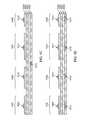
- FIG. 1 cis a schematic of an unwound electrolytic capacitive element with multiple capacitor sections with a common cathode.
- FIG. 1 dis a schematic of an unwound electrolytic capacitive element with multiple capacitor sections with separate cathodes.
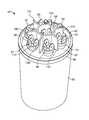
- FIG. 1 eis a perspective view of a capacitor.
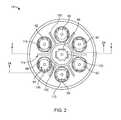
- FIG. 2is a top view of the capacitor of FIG. 1 e.
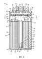
- FIG. 3is a sectional view of the capacitor of FIG. 1 e , taken along the lines 3 - 3 of FIG. 2 .
- FIG. 4is a side elevation view of the capacitive element of the capacitor of FIG. 1 e , including wire conductors connected to the capacitor sections thereof.
- FIG. 5is a top view of the capacitive element of the capacitor of FIG. 1 e , including wire conductors connected to capacitor sections thereof.
- FIG. 6is an enlarged fragmentary plan view of a distal end of a wire conductor of FIGS. 4 and 5 , connected to a foil tab.
- FIG. 7is an enlarged fragmentary side view of a distal end of a wire conductor of FIGS. 4 and 5 , connected to a foil tab.
- FIG. 8is a sectional view of the capacitor of FIG. 1 e taken along the lines 8 - 8 of FIG. 3 , and showing a pressure interrupter cover assembly of the capacitor of FIG. 1 e.
- FIG. 9is an exploded perspective view of the pressure interrupter cover assembly of the capacitor of FIG. 1 e.
- FIG. 10is an enlarged fragmentary view of the pressure interrupter cover assembly of the capacitor of FIG. 1 e.
- FIG. 11is a top view of the capacitor of FIG. 1 e , shown with selected capacitor sections connected to a fan motor and a compressor motor.
- FIG. 12is a schematic circuit diagram of the capacitor of FIG. 1 e connected as shown in FIG. 11 .
- FIG. 13is a top view of the capacitor of FIG. 1 with jumper wires connecting selected capacitor sections in parallel, and also shown connected in an electrical circuit to a fan motor and a compressor motor.
- FIG. 14is a schematic circuit diagram of the capacitor of FIG. 1 e connected as shown in FIG. 13 .
- FIG. 15is a top view of the capacitor of FIG. 1 connecting selected capacitor sections in series, and also shown connected in an electrical circuit to a motor.
- FIG. 16is a schematic circuit diagram of the capacitor of FIG. 1 e as connected shown in FIG. 15 .
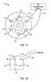
- FIG. 17is a top view of the capacitor of FIG. 1 with a jumper wire connecting selected capacitor sections in series, and also shown connected in an electrical circuit to a compressor motor.
- FIG. 18is a schematic circuit diagram of the capacitor of FIG. 1 e connected as shown in FIG. 17 .
- FIG. 19is a chart showing the single value capacitance values that may be provided by the capacitor of FIG. 1 e.
- FIG. 20is a chart showing dual value capacitances that may be provided by the capacitor of FIG. 1 .
- FIG. 21is another chart showing dual value capacitances that may be provided by the capacitor of FIG. 1 e.
- FIG. 22is another chart showing dual value capacitances that may be provided by the capacitor of FIG. 1 e.
- FIG. 23is another chart showing dual value capacitances that may be provided by the capacitor of FIG. 1 e.
- FIG. 24is a chart showing single value capacitances that may be provided by the capacitor of FIG. 1 e.
- FIG. 25is a sectional view of the capacitor of FIG. 1 e , taken generally along the lines 24 - 24 of FIG. 2 , but showing the capacitor after failure of the capacitive element.
- a desirable replacement capacitorwould have the electrical and physical characteristics of the failed capacitor, i.e. it should provide the same capacitance value or values at the same or higher voltage rating, be connectable using the same leads and be mountable on the same brackets or other mounting provision. It should also have the same safety protection, for example, as confirmed by independent tests performed by Underwriter Laboratories or others.
- the failed capacitorhas a relatively high capacitance value, e.g., tens or hundreds of microfarads.
- the replacement capacitormay be an electrolytic capacitor. Electrolytic capacitors generally have higher capacitance values than other types of capacitors.
- an electrolytic capacitor 500includes two electrically conductive material layers 501 and 502 (e.g. aluminum foils, tantalum foils, etc.) that are separated by a dielectric layer 503 .
- one electrode 501(the anode) is formed by an aluminum foil.
- An oxide layer 503(e.g., Al 2 O 3 ) is built up on the anode layer, thereby providing a dielectric.
- the counter electrode(the cathode) is a conductive liquid 504 (e.g., an electrolyte).
- a second aluminum foil 502 (the cathode foil)is placed in electrical contact with the liquid.
- the conductive liquid 504is provided by placing an electrolyte soaked paper 505 between the anode and the cathode foil, as shown.
- the dielectric oxide layer 503is formed by performing anode oxidation using electrolysis in an electrolytic solution (note, this electrolytic solution is generally different from the electrolyte used for the conducting fluid of the cathode).
- the electrolytic solutionis an aqueous solution such as ammonium boric acid or ammonium phosphate.
- the thickness of the grown thin filmis nearly proportional to the applied voltage used in the electrolysis process.
- the dielectric properties of the filmgenerally depend on the details of the formations process.
- the dielectric constant of a typical aluminum oxide layercan range between 7 and 8 times the permittivity of free space.
- the conductive liquid 504flows into intimate contact with the dielectric oxide layer 503 on the anode foil 501 , thereby minimizing the distance between the cathode 502 and anode 501 .
- the surface area of the anode layer 501can be increased by roughing the surface using an etching process (e.g., physical etching using an acid such as hydrochloric acid, or electrochemical etching).
- an etching processe.g., physical etching using an acid such as hydrochloric acid, or electrochemical etching.
- FIG. 1 bshows a schematic diagram of a wound, multi-section aluminum foil electrolytic capacitive element.
- Each of the multiple capacitor sectionshas a capacitance value.
- One or more of the sectionscan be connected to an electrical circuit to provide a desired capacitance.
- FIG. 1 cshows the capacitive element of FIG. 1 b unwound.
- Aluminum cathode foil 1001is placed upon nonconductive spacer paper 1002 .
- Electrolyte soaked paper 1003is placed upon cathode foil 1001 .
- Aluminum anode foil 1004which includes an oxide layer on its bottom face, is placed on top of electrolyte soaked paper 1003 .
- Anode foil 1004is cut into sections, thereby forming multiple capacitive sections 1005 , 1006 , 1007 , 1008 .
- Each sectionincludes a distinct anode and dielectric, and all four section share a common cathode.
- the capacitance of each sectiondepends on, for example, the surface area of the corresponding anode.
- capacitive sectionscan be provided with various desired capacitance values by, for example, cutting the cathode foil strip into sections of varying length.
- Tabs 1009 , 1010 , 1011 , and 1012are placed in electrical contact with the anode foil of capacitive sections 1005 , 1006 , 1007 , and 1008 respectively.
- Tab 1013is placed in electrical contact with cathode foil 1001 .
- the tabsare crimped to the corresponding foil.
- each sectioninclude an independent cathode.
- cathode foil 1001is cut into sections, as shown in FIG. 1 d .
- Tabs 1013 , 1014 , 1015 , and 1016are placed in contact with the cathode foils of are placed in electrical connection with the cathode foil of capacitive sections 1005 , 1006 , 1007 , and 1008 respectively.
- electrolyte soaked paper 1003may be cut into sections along with the anode and/or cathode foils.
- the position of the anode and cathode foilscan be reversed.
- electrical connections other than tabsare used.
- wiresmay be connected directly to the foils using, e.g. soldering.
- solderinge.g. soldering
- paper spacer 1002insulates the capacitor sections from each other.
- Tabs 1009 , 1010 , 1011 , and 1012extend beyond the top of wound paper spacer 1002 allowing electrical connection with the anodes of capacitor sections 1005 , 1006 , 1007 , and 1008 respectively.
- Tab 1013extends beyond the bottom of wound paper spacer 1002 , allowing electrical connection with the common cathode 1001 .
- a capacitor 10is shown in FIGS. 1 e , 2 and 3 as well as in other figures to be described below.
- the capacitor 10is adapted to replace any one of a large number of capacitors. Therefore, a serviceman may carry a capacitor 10 on a service call and, upon encountering a failed capacitor, the serviceman can utilize the capacitor 10 to replace the failed capacitor with the capacitor 10 being connected to provide the same capacitance value or values of the failed capacitor.
- the capacitor 10has a wound electrolytic capacitive element 12 of the type described above having a plurality of capacitor sections, each having a capacitance value.
- the capacitive element 12is also shown in FIGS. 4 and 5 .
- the capacitive element 12has six capacitor sections 20 , 21 , 22 , 23 , 24 , and 25 .
- each capacitive elementincludes an oxide coated anode foil, an electrolyte soaked paper, and a cathode foil, layered upon each other. Separate anodes are provided for each section by, for example, cutting the anode foil into sections as described above. In the pictured embodiment, the capacitor sections share a common cathode.
- each capacitor sectioncan have a separate cathode.
- the electrolytic capacitive element 12has six capacitor sections 20 - 25 .
- the electrolytic capacitive element 12is a wound cylindrical element. Accordingly, the capacitive element 12 has a central spool or mandrel 28 , which has a central opening 29 .
- An element insulation barrier 30is provided to separate the six capacitor sections 20 - 25 .
- the element insulation barriercorresponds to paper 1002 shown in FIG. 1 b .
- the element insulation barriermay be insulating polymer sheet material, for example polypropylene.
- an element common cathode terminal 36is established by contacting a tab in electrical contact with common cathode foil of the capacitive element to foil strip conductor 38 at 37 .
- multiple cathode terminalsare provided.
- the element insulation barrier 30extends above the wound aluminum foils of the capacitor sections.
- An individual capacitor element section terminal tabis provided for each of the capacitive sections 20 - 25 .
- the element section terminal tabsare identified by numerals 40 - 45 .
- Each element section terminal tabis electrical in contact with the anode foil of the corresponding capacitor section.
- Element section terminals tabs 40 - 45are respectively deployed on the capacitor sections 20 - 25 .
- Conductors preferably in the form of six insulated wires 50 - 55each have one of their ends respectively soldered to the element section terminal tabs 40 - 45 , as best seen in FIG. 5 .
- the insulation of the wires 50 - 55is color coded to facilitate identifying which wire is connected to which capacitor section.
- Wire 50 connected to element section terminal 40 of capacitor section 20has blue insulation
- wire 51 connected to element section terminal 41 of capacitor section 21has yellow insulation
- wire 52 connected to element section terminal 42 of capacitor section 22has red insulation
- wire 53 connected to element section terminal 43 of capacitor section 23has white insulation
- wire 54 connection to element section terminal 44 of capacitor section 24has white insulation
- wire 55 connected to element section terminal 45 of capacitor section 25has green insulation.
- the capacitive element 12is further provided with foil strip conductor 38 , having one end attached to the element common cathode terminal 36 at 37 .
- the foil strip conductor 38is coated with insulation, except for the point of attachment 37 and the distal end 39 thereof. If desired, foil or wire conductors may be utilized for all connections.
- the capacitor section 20has a value of approximately 25.0 microfarads and the capacitor section 21 has a capacitance of approximately 20.0 microfarads.
- the capacitor section 22has a capacitance of approximately 10.0 microfarads.
- the capacitor section 23has a capacitance of approximately 5.5 microfarads, but is identified as having a capacitance of 5.0 microfarads for purposes further discussed below.
- the capacitor section 24has a capacitance of approximately 4.5 microfarads but is labeled as having a capacitance of 5 microfarads, again for purposes described below.
- the capacitor section 25has a capacitance of approximately 2.8 microfarads.
- the capacitor 10also has a case 60 , best seen in FIGS. 1-3 , having a cylindrical side wall 62 , a bottom wall 64 , and an open top 66 of side wall 62 .
- the case 60is formed of aluminum and the cylindrical side wall 62 has an outside diameter of 2.50 inches. This is a very common diameter for capacitors of this type, wherein the capacitor 10 will be readily received in the mounting space and with the mounting hardware provided for the capacitor being replaced. Other diameters may, however, be used, and the case may also be plastic or of other suitable material.
- the capacitive element 12 with the wires 50 - 55 and the foil strip 38are received in the case 60 with the element common terminal 36 adjacent the bottom wall 64 of the case.
- An insulating bottom cup 70is preferably provided for insulating the capacitive element from the bottom wall 64 , the bottom cup 70 having a center post 72 that is received in the center opening 29 of the mandrel 28 , and an up-turned skirt 74 that embraces the lower side wall of the cylindrical capacitive element 12 and spaces it from the side wall 62 of the case 60 .
- an insulating fluid 76is provided within the case 60 , at least partly and preferably substantially surrounding the capacitive element 12 .
- the fluid 76may be the fluid described in U.S. Pat. No. 6,014,308, incorporated herein by reference.
- the fluidmay be one of the other insulating fluids used in the trade, such as polybutene or insulating oil.
- the fluidmay be replaced by other types of insulating materials such as, for example, dielectric greases.
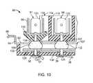
- the capacitor 10also has a pressure interrupter cover assembly 80 best seen in FIGS. 1-3 , 8 - 10 and 24 .
- the cover assembly 80includes a deformable circular cover 82 having an upstanding cylindrical skirt 84 and a peripheral rim 86 as best seen in FIGS. 9 and 10 .
- the skirt 84fits into the open top 66 cylindrical side wall 62 of case 60
- the peripheral rim 86is crimped to the open top 66 of the case 60 to seal the interior of the capacitor 10 and the fluid 76 contained therein, as shown in FIGS. 1 and 3 .
- the pressure interrupter cover assembly 80includes seven cover terminals mounted on the deformable cover 82 .
- a common cathode cover terminal 88is mounted generally centrally on the cover 82
- section cover terminals 90 - 95are mounted at spaced apart locations surrounding the common cover terminal 88 .
- multiple cathode terminalsare provided.
- the section cover terminal 91has three upstanding blades 98 , 100 and 102 mounted on the upper end of a terminal post 104 .
- Terminal post 104has a distal end 105 , opposite the blades 98 , 100 and 102 .
- the cover 82has an opening 106 for accommodating the terminal post 104 , and has a beveled lip 107 surrounding the opening.
- a shaped silicone insulator 108fits under the cover in the beveled lip 107 and the terminal post 104 passes through the insulator 108 .
- an insulator cup 110also surrounds the post 104 , and the insulator cup 110 sits atop the silicone insulator 108 ; thus, the terminal 91 and its terminal post 104 are well insulated from the cover 82 .
- the other cover section terminals 92 - 95are similarly mounted with an insulator cup and a silicone insulator.
- the common cathode cover terminal 88has four blades 120 , and a terminal post 122 that passes through a silicone insulator 112 .
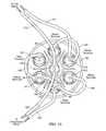
- the common cathode cover terminal 88mounts cover insulator barrier 114 that includes an elongated cylindrical center barrier cup 116 surrounding and extending above the blades 120 of the common cathode cover terminal 88 , and six barrier fins 118 that extend respectively radially outwardly from the elongated center barrier cup 116 such that they are deployed between adjacent section cover terminals 90 - 95 . This provides additional protection against any arcing or bridging contact between adjacent section cover terminals or with the common cathode cover terminal 88 .
- the common cathode cover terminal 88may be provided with an insulator cup 116 , preferably extending above blades 120 but with no separating barrier fins, although the barrier fins 118 are preferred.
- the terminal post 122extends through an opening in the bottom of the base 117 of the insulating barrier cup 116 , and through the silicone insulator 112 , to a distal end 124 .
- the pressure interrupter cover assembly 80has a fiberboard disc 126 through which the terminal posts 122 , terminal post 104 and the terminal posts of the other section cover terminals extend.
- the disc 126may be also fabricated of other suitable material, such as polymers.
- the terminal posts 104 , 122 , etc.are configured as rivets with rivet flanges 128 for assembly purposes.
- the terminal posts 104 , 122 , etc.are inserted through the disc 126 , insulators 108 , 112 , insulator cups 110 and barrier cup 116 , and the cover terminals 88 , 90 - 95 are spot welded to the ends of the rivets opposite the rivet flanges 128 .
- the rivet flanges 128secure the cover terminals 88 , 90 - 95 in the cover 82 , together with the insulator barrier 114 , insulator cups 110 and silicone insulators 108 , 112 .
- the fiberboard disc 126facilitates this assembly, but may be omitted, if desired.
- the distal ends of the terminal postsare preferably exposed below the rivet flanges 128 .
- the cover assembly 80has a disconnect plate 130 , perhaps best seen in FIGS. 3 , 9 and 10 .
- the disconnect plate 130is made of a rigid insulating material, such as a phenolic, is spaced below the cover 82 by a spacer 134 in the form of a skirt.
- the disconnect plate 130is provided with openings accommodating the distal ends of the terminal posts, such as opening 136 accommodating the distal end 105 of terminal post 104 and opening 138 accommodating the distal end 124 of the terminal post 122 .
- the disconnect plate 130may be provided with raised guides, such as linear guides 140 and dimple guides 142 , generally adjacent the openings accommodating the distal ends of terminal posts. These guides are for positioning purposes as discussed below.
- the distal end 39 of the foil strip 38is connected to the distal end 124 of terminal post 122 by welding.
- the conductors between the capacitor sections and the terminal postsare foil strips, such as the one used for the common cathode terminal 36 of the capacitive element 12 herein.
- the foil stripsare positioned on a breaker plate over the distal ends of terminal posts, and are welded to the distal ends of the terminal posts.
- the wires 50 - 55are not well-configured for welding to the distal ends of the terminal posts of the cover section terminals. However, the wires 50 - 55 are desirable in place of foil strips because they are better accommodated in the case 60 and have good insulating properties, resist nicking and are readily available with colored insulations. In order to make the necessary connection of the wires 50 - 55 to their respective terminal posts, foil tabs 56 are welded to each of the distal ends of the terminal posts of the section cover terminals 90 - 95 , and the guides 140 , 142 are helpful in positioning the foil tabs 56 for the welding procedure.
- the attachmentmay be accomplished by welding the distal end of a foil strip to the terminal post, and then cutting the foil strip to leave the foil tab 56 . Thereafter, and as best seen in FIGS. 6 , 7 and 10 , the conductor 58 of wire 50 is soldered to the tab 56 , by solder 57 . The insulation 59 of wire 50 has been stripped to expose the conductor 58 . The other wires 51 - 55 are similarly connected to their respective cover section terminals. Alternatively, the foil tabs may be soldered to the wires and the tabs may then be welded to the terminal posts, if desired, or other conductive attachment may be employed.
- each of the capacitor sections 20 - 25is connected to a corresponding section cover terminal 90 - 95 by a respective one of color coded wires 50 - 55 .
- the insulator cups 10 associated with each of the section cover terminals 90 - 95are also color coded, using the same color scheme as used in the wires 50 - 55 . This facilitates assembly, in that each capacitor section and its wire conductor are readily associated with the correct corresponding section cover terminal, so that the correct capacitor sections can be identified on the cover to make the desired connections for establishing a selected capacitance value.
- the connections of the wires 50 - 55 and the foil 38 to the terminal postsis made prior to placing the capacitive element 12 in the case 60 , adding the insulating fluid 76 , and sealing the cover 82 of cover assembly 80 to the case 60 .
- the case 60may be labeled with the capacitance values of the capacitance sections 20 - 25 adjacent the cover terminals, such as on the side of case 60 near the cover 82 or on the cover 82 .
- the capacitor 10may be used to replace a failed capacitor of any one of over two hundred different capacitance values, including both single and dual applications. Therefore, a serviceman is able to replace virtually any failed capacitor he may encounter as he makes service calls on equipment of various manufacturers, models, ages and the like.
- the capacitor 10is expected to be used widely in servicing air conditioning units.
- Air conditioning unitstypically have two capacitors; a capacitor for the compressor motor which may or may not be of relatively high capacitance value and a capacitor of relatively low capacitance value for a fan motor.
- the compressor motor capacitorstypically have capacitances of from 20 to about 60 microfarads.
- the fan motor capacitorstypically have capacitance values from about 2.5 to 12.5 microfarads, and sometimes as high as 15 microfarads, although values at the lower end of the range are most common.
- capacitor 10is connected to replace a compressor motor capacitor and a fan motor capacitor, where the compressor motor capacitor has a value of 25.0 microfarads and the fan motor capacitor has a value of 4.0 microfarads.
- the 25.0 microfarad replacement capacitance for the compressor motoris made by one of the compressor motor leads 160 being connected to one of the blades of the blue section cover terminal 90 of capacitance section 20 , which has a capacitance value of 25.0 microfarads, and the other compressor motor lead 161 being connected to one of the blades 120 of common cathode cover terminal 88 .
- the lead 162 from the fan motoris connected to the white section cover terminal 94 of capacitor section 24
- the second lead 163 from the fan motoris also connected to the common cathode cover terminal 88 .
- the actual capacitance value of the capacitor section 24 that is connected to the section cover terminal 94is 4.5 microfarads
- the instructions and/or labeling for the capacitor 10indicate that the capacitor section 24 as represented at terminal 94 should be used for a 4.0 microfarad replacement.
- Preferred labeling for this purposecan be “5.0 (4.0) microfarads” or similar.
- the 4.5 microfarad capacitance valueis within approximately 10% of the specified 4.0 microfarad value, and that is within acceptable tolerances for proper operation of the fan motor.
- capacitor section 24 and terminal 94may be connected to replace a 5.0 microfarad capacitance value as well, whereby the 4.5 microfarad actual capacitance value of capacitor section 24 gives added flexibility in replacing failed capacitors.
- the 5.5 microfarad capacitor section 23can be used for either 5.0 microfarad or 6.0 microfarad replacement, and the 2.8 microfarad section 25 can be used for a 3.0 microfarad replacement or for a 2.5 microfarad additive value.
- FIG. 12schematically illustrates the connection of capacitor sections 20 and 24 to the compressor motor and fan motor shown in FIG. 11 .
- FIG. 13illustrates another connection of the capacitor 10 for replacing a 60.0 microfarad compressor motor capacitor and a 7.5 microfarad fan motor capacitor.
- a 60.0 microfarad capacitance value for the compressor motoris achieved by connecting in parallel the section cover terminal 90 (capacitor section 20 at a value of 25.0 microfarads), section cover terminal 91 (capacitor section 21 at a value of 20.0 microfarads), section cover terminal 92 (capacitor section 22 at a value of 10.0 microfarads) and section cover terminal 93 (capacitor section 23 at a nominal value of 5.0 microfarads).
- the foregoing connectionsare made by means of jumpers 164 , 165 and 166 , which may be supplied with the capacitor 10 .
- Lead 167is connected from the section cover terminal 90 of the capacitor section 20 , e.g., to the compressor motor, and lead 168 is connected from the common cathode cover terminal 88 , e.g., to the compressor motor.
- FIG. 14diagrammatically illustrates the connection of the capacitor 10 shown in FIG. 13 .
- the capacitor sectionscan also be connected in series to utilize capacitor 10 as a single value replacement capacitor.
- Thishas the added advantage of increasing the voltage rating of the capacitor 10 in a series application, i.e. the capacitor 10 can safely operate at higher voltages when its sections are connected in series.
- the operating voltagewill not be increased as it is established by the existing equipment and circuit, and the increased voltage rating derived from a series connection will increase the life of the capacitor 10 because it will be operating well below its maximum rating.
- the capacitor 10is shown with capacitor section 22 (terminal 92 ) having a value of 10.0 microfarads connected in series with capacitor section 25 (terminal 95 ) having a nominal value of 2.5 microfarads to provide a replacement capacitance value of 2.0 microfarads.
- Leads 162 and 163make the connections from the respective section cover terminals 92 and 95 to the motor, and the element common cathode terminal 36 connects the capacitor sections 22 and 25 of capacitive element 12 .
- FIG. 16the connection of capacitor 10 shown in FIG. 15 is illustrated diagrammatically. In both FIGS. 15 and 16 , it will be seen that the cover common cathode terminal 88 is not used in making series connections.
- the total capacitance of the capacitor sections 22 and 25 connected as shown in FIGS. 15 and 16is 2.0 microfarads.
- the capacitance of each of the capacitor sections 20 - 25is rated at 440 volts.
- the applied voltage sectionis divided between the capacitor sections in inverse proportion to their value.
- the nominal 2.5 microfarad sectionsees about 80% of the applied voltage
- the 10.0 microfarad sectionsees about 20% of the applied voltage.
- the net effectis that the capacitor 10 provides the 2.0 microfarad replacement value at a higher rating, due to the series connection. In this configuration, the capacitor 10 is lightly stressed and is apt to have an extremely long life.
- the capacitor sections of the capacitor 10are shown connected in a combination of parallel and series connections to provide additional capacitive values at high voltage ratings, in this case 5.0 microfarads.
- the two capacitor sections 23 and 24 each having a nominal value of 5.0 microfaradsare connected in parallel by jumper 177 between their respective cover section terminals 93 and 94 .
- the leads 178 and 179 from a compressor motorare connected to the section cover terminal 92 of capacitor section 22 having a value of 10.0 microfarads, and the other lead is connected to cover section terminal 94 of capacitor section 24 .
- a capacitance value of 5.0 microfaradsis provided according to the following formula
- the connection of capacitor 10 illustrated in FIG. 17is shown diagrammatically in FIG. 18 .
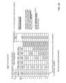
- FIG. 19is a chart showing single capacitance values that can be provided by the capacitor 10 connected in parallel. The values are derived by connecting individual capacitor sections into a circuit, or by parallel connections of capacitor sections. The chart should be interpreted remembering that the 2.8 microfarad capacitor section can be used as a 2.5 or 3.0 microfarad replacement, and that the two 5.0 microfarad values are actually 4.5 and 5.5 microfarad capacitor sections, also with possibilities for more replacements.
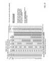
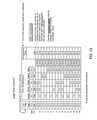
- FIGS. 20-23are charts showing applications of capacitor 10 in replacing both a fan motor capacitor and a compressor motor capacitor. This is an important capability, because many air conditioning systems are equipped with dual value capacitors and when one of the values fails, another dual value capacitor must be substituted into the mounting space bracket.
- the chart of FIG. 20shows dual value capacitances that can be provided by capacitor 10 wherein the nominal 2.5 microfarad capacitor section 25 is used for one of the dual values, usually the fan motor. Fan motors are generally not rigid in their requirements for an exact capacitance value, wherein the capacitor section 25 may also be used for fan motors specifying a 3.0 microfarad capacitor.
- the remaining capacitor sections 20 - 24are available for connection individually or in parallel to the compressor motor, providing capacitance values from 5.0 to 65.0 microfarads in 5.0 microfarad increments.
- the chart of FIG. 21also shows dual value capacitances that can be provided by capacitor 10 .
- one of the dual valuesis 5.0 microfarads that can be provided by either capacitor section 23 having an actual capacitance value of 5.5 microfarads or by capacitor section 24 having an actual capacitance of 4.5 microfarads.
- the capacitor section 24can also be used for a 4.0 microfarad replacement value, and capacitor section 23 could be used for a 6.0 microfarad replacement value.
- chart 21represents more dual replacement values than are specifically listed.
- the other capacitor sectionmay be used in various parallel connections to achieve the second of the dual capacitance values.
- the chart of FIG. 22illustrates yet additional dual value capacitances that can be provided by capacitor 10 .
- Capacitor section 25(nominal 2.5 microfarads) is connected in parallel with one of capacitor section 23 (5.5 microfarads) or capacitor section 24 (4.5 microfarads) to provide a 7.5 microfarad capacitance value as one of the dual value capacitances.
- the remaining capacitor sectionsare used individually or in parallel to provide the second of the dual value capacitances.
- the chart of FIG. 23illustrates yet additional dual value capacitances that can be provided by capacitor 10 , where capacitor section 22 (10 microfarads) is dedicated to provide one of the dual values. The remaining capacitor sections are used individually or in parallel for the other of the dual values.
- any one or group of capacitor sectionsmay be used for one of a dual value, with a selected one or group of the remaining capacitor sections connected to provide another capacitance value. It will also be appreciated that the capacitor 10 could provide six individual capacitance values corresponding to the capacitor sections, or three, four or five capacitance values in selected individual and parallel connections. Additional single values can be derived from series connections.
- the six capacitor sections 20 - 25can provide hundreds of replacement values, including single and dual values. It will further be appreciated that if fewer replacement values are required, the capacitor 10 can be made with fewer than six capacitor sections, and that if more replacement values were desired, the capacitor 10 could be made with more than six capacitor sections
- capacitor 10is a replacement capacitor for a “motor-run” capacitor.
- the capacitance values for capacitance sections 20 - 25are about 22.5 microfarads, about 33.0 microfarads, about 40.0 microfarads, about 45.0 microfarads, about 70.0 microfarads, and about 90 microfarads, respectively.
- the color of white terminal 94is changed to purple to indicate that corresponds to a capacitor section with a different capacitance value than that of terminal 93 .
- the chart of FIG. 24illustrates a number of single vale capacitances that can be provided by capacitor 10 .
- the 70 microfarad, 45 microfarad, and 22.5 microfarad capacitor sectionscan be connected in parallel as described above to provide a single capacitance vale of 107.5 microfarads.
- capacitance values for capacitance sections 20 - 25are about 20 microfarads, about 30 microfarads, about 55 microfarads, about 67 microfarads, about 70.0 microfarads, and about 83 microfarads, respectively.
- capacitor 10can provide single, dual, or multiple capacitance values over a variety of ranges. In some embodiments, capacitor 10 may provide capacitance values of, for example, up to 300 microfarads or more or about 400 microfarads or more. Capacitor 10 can also include capacitor sections with a variety of voltage ratings, thereby providing a suitable replacement for a range of capacitors with different operating voltages.
- the pressure interrupter cover assembly 80provides such protection for the capacitor 10 and its capacitive element 12 .
- the capacitor 10is shown after failure. Outgassing has caused the circular cover 82 to deform upwardly into a generally domed shape.
- the terminal postsare also displaced upwardly from the disconnect plate 130 , and the weld connection of the distal end 124 of common cathode cover terminal post 122 to the distal end 39 foil lead 38 from the common cathode element 36 of the capacitive element 12 is broken, and the welds between the foil tabs 56 and the terminal posts 104 of the section cover terminals 90 - 95 are also broken, the separation at section cover terminals 91 and 94 being shown.
- the preferred pressure interrupter cover assemblyincludes the foil lead 38 and foil tabs 56 , frangibly connected to the distal ends of the terminal posts, the frangible connections both known in the art and to be developed may be used.
- the terminal poststhemselves may be frangible.
- the capacitor sections of the capacitor 10are utilized in a series connection, it is necessary that only one of the terminal posts used in the series connection be disconnected from its foil tab at the disconnect plate 130 to remove the capacitive element from an electrical circuit.
- the outgassing conditionwill persist until the pressure interrupter cover assembly 80 deforms sufficiently to cause disconnection from the circuit, and it is believed that an incremental amount of outgassing may occur as required to cause sufficient deformation and breakage of the circuit connection at the terminal post of one of the section cover terminal.
- the common cover terminal 88may be used and the central location of the common cover terminal 88 may cause fast and certain disconnect upon any failure of the capacitive element.
- the common cover terminal 88may be twisted to pre-break the connection of the terminal post 122 with the foil strip 38 , thus eliminating the requirement of any force to break that connection in the event of a failure of the capacitive element 12 .
- the force that would otherwise be needed to break the connection of common terminal post 122is then applied to the terminal posts of the section cover terminals, whereby the section cover terminals are more readily disconnected. This makes the pressure interrupter cover assembly 80 highly responsive in a series connection configuration.
- the structural aspects of welding foil tabs to the distal ends of the terminal posts corresponding to the various capacitor sections and thereafter soldering the connecting wires onto the foil tabs 56is also believed to make the pressure interrupter cover assembly 80 more responsive to failure of the capacitive element 12 .
- the solder and wiregreatly enhance the rigidity of the foil tabs 56 wherein upon deformation of the cover 82 , the terminal posts break cleanly from the foil tabs 56 instead of pulling the foil tabs partially through the disconnect plate before separating.
- electrolytic capacitor sections of the foil typeother types of capacitor sections may be used including tantalum electrolytic, electrolytic double-layer, or aerogel.
- one or more capacitor sectionsmay be a non electrolytic capacitor section.
- capacitor 10could include capacitor sections which are of the ceramic type, silver mica type, plastic film type, tantalum type, and/or polyester film type.
- the capacitor sectionsmay include a combination of capacitor types.
- the foil strip used to connect the common cathode terminal of capacitor element 12 to the common cathode cover terminal 88may be replaced by an insulated wire.
- Various electrical contactsmay be provided by any method including, for example, crimping, soldering and/or welding.
Landscapes
- Engineering & Computer Science (AREA)
- Power Engineering (AREA)
- Microelectronics & Electronic Packaging (AREA)
- Fixed Capacitors And Capacitor Manufacturing Machines (AREA)
- Manufacturing & Machinery (AREA)
Abstract
Description
Ctotal=C1+C2+C3+
Claims (31)
Priority Applications (7)
| Application Number | Priority Date | Filing Date | Title |
|---|---|---|---|
| US13/116,461US8537522B2 (en) | 2006-12-29 | 2011-05-26 | Electrolytic capacitor |
| US13/965,591US9424995B2 (en) | 2006-12-29 | 2013-08-13 | Electrolytic capacitor |
| US15/227,008US10056195B2 (en) | 2006-12-29 | 2016-08-03 | Electrolytic Capacitor |
| US16/041,575US11631550B2 (en) | 2006-12-29 | 2018-07-20 | Electrolytic capacitor with multiple sections |
| US16/780,497US11183341B1 (en) | 2006-12-29 | 2020-02-03 | Electrolytic capacitive device |
| US17/532,185US12293879B2 (en) | 2006-12-29 | 2021-11-22 | Electrolytic capacitive device |
| US19/031,081US20250239415A1 (en) | 2006-12-29 | 2025-01-17 | Electrolytic capacitive device |
Applications Claiming Priority (3)
| Application Number | Priority Date | Filing Date | Title |
|---|---|---|---|
| US88281306P | 2006-12-29 | 2006-12-29 | |
| US11/966,358US7952854B2 (en) | 2006-12-29 | 2007-12-28 | Electrolytic capacitor |
| US13/116,461US8537522B2 (en) | 2006-12-29 | 2011-05-26 | Electrolytic capacitor |
Related Parent Applications (1)
| Application Number | Title | Priority Date | Filing Date |
|---|---|---|---|
| US11/966,358ContinuationUS7952854B2 (en) | 2006-12-29 | 2007-12-28 | Electrolytic capacitor |
Related Child Applications (1)
| Application Number | Title | Priority Date | Filing Date |
|---|---|---|---|
| US13/965,591ContinuationUS9424995B2 (en) | 2006-12-29 | 2013-08-13 | Electrolytic capacitor |
Publications (2)
| Publication Number | Publication Date |
|---|---|
| US20110228446A1 US20110228446A1 (en) | 2011-09-22 |
| US8537522B2true US8537522B2 (en) | 2013-09-17 |
Family
ID=39583566
Family Applications (8)
| Application Number | Title | Priority Date | Filing Date |
|---|---|---|---|
| US11/966,358Active2029-11-11US7952854B2 (en) | 2006-12-29 | 2007-12-28 | Electrolytic capacitor |
| US13/116,461ActiveUS8537522B2 (en) | 2006-12-29 | 2011-05-26 | Electrolytic capacitor |
| US13/965,591ActiveUS9424995B2 (en) | 2006-12-29 | 2013-08-13 | Electrolytic capacitor |
| US15/227,008ActiveUS10056195B2 (en) | 2006-12-29 | 2016-08-03 | Electrolytic Capacitor |
| US16/041,575ActiveUS11631550B2 (en) | 2006-12-29 | 2018-07-20 | Electrolytic capacitor with multiple sections |
| US16/780,497ActiveUS11183341B1 (en) | 2006-12-29 | 2020-02-03 | Electrolytic capacitive device |
| US17/532,185ActiveUS12293879B2 (en) | 2006-12-29 | 2021-11-22 | Electrolytic capacitive device |
| US19/031,081PendingUS20250239415A1 (en) | 2006-12-29 | 2025-01-17 | Electrolytic capacitive device |
Family Applications Before (1)
| Application Number | Title | Priority Date | Filing Date |
|---|---|---|---|
| US11/966,358Active2029-11-11US7952854B2 (en) | 2006-12-29 | 2007-12-28 | Electrolytic capacitor |
Family Applications After (6)
| Application Number | Title | Priority Date | Filing Date |
|---|---|---|---|
| US13/965,591ActiveUS9424995B2 (en) | 2006-12-29 | 2013-08-13 | Electrolytic capacitor |
| US15/227,008ActiveUS10056195B2 (en) | 2006-12-29 | 2016-08-03 | Electrolytic Capacitor |
| US16/041,575ActiveUS11631550B2 (en) | 2006-12-29 | 2018-07-20 | Electrolytic capacitor with multiple sections |
| US16/780,497ActiveUS11183341B1 (en) | 2006-12-29 | 2020-02-03 | Electrolytic capacitive device |
| US17/532,185ActiveUS12293879B2 (en) | 2006-12-29 | 2021-11-22 | Electrolytic capacitive device |
| US19/031,081PendingUS20250239415A1 (en) | 2006-12-29 | 2025-01-17 | Electrolytic capacitive device |
Country Status (2)
| Country | Link |
|---|---|
| US (8) | US7952854B2 (en) |
| WO (1) | WO2008083270A1 (en) |
Cited By (26)
| Publication number | Priority date | Publication date | Assignee | Title |
|---|---|---|---|---|
| US20130214720A1 (en)* | 2009-11-13 | 2013-08-22 | American Radionic Company, Inc. | Hard Start Kit for Multiple Replacement Applications |
| US20130343029A1 (en)* | 2005-04-07 | 2013-12-26 | American Radionic Company, Inc. | Capacitor with multiple elements for multiple replacement applications |
| USD729164S1 (en)* | 2013-09-02 | 2015-05-12 | Foshan City Shunde District Lun Jiao Sheng Ye Electrical Co., Ltd | Capacitor |
| US9318261B2 (en) | 2013-05-21 | 2016-04-19 | American Radionic Company, Inc. | Power factor correction capacitors |
| US9343238B2 (en) | 2005-04-07 | 2016-05-17 | American Radionic Company, Inc. | Capacitor for multiple replacement applications |
| US9412521B2 (en) | 2005-04-07 | 2016-08-09 | American Radionic Company, Inc. | Capacitor with multiple elements for multiple replacement applications |
| US9424995B2 (en) | 2006-12-29 | 2016-08-23 | American Radionic Company, Inc. | Electrolytic capacitor |
| US9859060B1 (en) | 2017-02-07 | 2018-01-02 | American Radionic Company, Inc. | Capacitor with multiple elements for multiple replacement applications |
| US9911533B2 (en) | 2016-06-28 | 2018-03-06 | Cornell Dubilier Electronics, Inc. | Capacitor with pressure interrupter |
| USD818437S1 (en) | 2005-12-23 | 2018-05-22 | American Radionic Company, Inc. | Capacitor |
| US10147550B1 (en) | 2018-04-27 | 2018-12-04 | American Radionic Company, Inc. | Capacitor with multiple elements for multiple replacement applications |
| US10497518B1 (en) | 2017-12-13 | 2019-12-03 | American Radionic Company, Inc. | Hard start kit for multiple replacement applications |
| US10586655B1 (en) | 2018-12-28 | 2020-03-10 | American Radionic Company, Inc. | Capacitor with multiple elements for multiple replacement applications |
| USD906247S1 (en) | 2019-07-11 | 2020-12-29 | American Radionic Company, Inc. | Capacitor |
| US11183336B2 (en) | 2005-04-07 | 2021-11-23 | Amrad Manufacturing, Llc | Capacitor with multiple elements for multiple replacement applications |
| US11183338B2 (en) | 2005-04-07 | 2021-11-23 | Amrad Manufacturing, Llc | Capacitor with multiple elements for multiple replacement applications |
| US11183337B1 (en) | 2005-04-07 | 2021-11-23 | Amrad Manufacturing, Llc | Capacitor with multiple elements for multiple replacement applications |
| US11195663B2 (en) | 2017-05-12 | 2021-12-07 | Amrad Manufacturing, Llc | Capacitor with multiple elements for multiple replacement applications |
| US11424077B1 (en) | 2017-12-13 | 2022-08-23 | Amrad Manufacturing, Llc | Hard start kit for multiple replacement applications |
| US11575298B2 (en) | 2021-04-30 | 2023-02-07 | Amrad Manufacturing, Llc | Hard start kit for multiple replacement applications |
| US12125645B1 (en) | 2019-06-07 | 2024-10-22 | Amrad Manufacturing, Llc | Capacitor with multiple elements for multiple replacement applications |
| USD1052528S1 (en) | 2019-06-25 | 2024-11-26 | Amrad Manufacturing, Llc | Capacitor |
| USD1054379S1 (en) | 2020-11-24 | 2024-12-17 | Amrad Manufacturing, Llc | Capacitor with relay |
| USD1055860S1 (en) | 2018-12-13 | 2024-12-31 | Amrad Manufacturing, Llc | Magnet for attachment to a capacitor |
| US12272503B2 (en) | 2017-05-12 | 2025-04-08 | Amrad Manufacturing, Llc | Capacitor with multiple elements for multiple replacement applications |
| US12437918B2 (en) | 2023-09-22 | 2025-10-07 | Amrad Manufacturing, Llc | Capacitor mount |
Families Citing this family (8)
| Publication number | Priority date | Publication date | Assignee | Title |
|---|---|---|---|---|
| MY163624A (en)* | 2009-12-31 | 2017-10-13 | Specscan Sdn Bhd | Low inductance integrel capacitor assembly |
| US9142352B2 (en) | 2013-08-30 | 2015-09-22 | Cornell-Dubilier Marketing, Inc. | Capacitor for high g-force applications |
| WO2015031099A1 (en)* | 2013-08-30 | 2015-03-05 | Cornell-Dubilier Marketing, Inc. | Capacitor for high g-force applications |
| US9916934B1 (en)* | 2016-04-11 | 2018-03-13 | Cornell Dubilier Electronics, Inc. | Multi-rated capacitor assembly |
| CN110706930A (en)* | 2019-08-20 | 2020-01-17 | 深圳云容新能源有限公司 | High-voltage solid-liquid mixed type aluminum electrolytic capacitor and preparation method thereof |
| TWI718960B (en)* | 2020-06-10 | 2021-02-11 | 鈺邦科技股份有限公司 | Winding-type capacitor package structure and method of manufactured the same |
| TWI719908B (en)* | 2020-06-10 | 2021-02-21 | 鈺邦科技股份有限公司 | Winding-type capacitor package structure and method of manufactured the same |
| US20220153759A1 (en)* | 2020-11-17 | 2022-05-19 | Universal Display Corporation | Organic electroluminescent materials and devices |
Citations (48)
| Publication number | Priority date | Publication date | Assignee | Title |
|---|---|---|---|---|
| US3304473A (en) | 1963-11-12 | 1967-02-14 | Sprague Electric Co | Nonbursting electrical capacitor |
| US3377510A (en) | 1967-11-09 | 1968-04-09 | Gen Electric | Electrical apparatus |
| US3921041A (en) | 1975-02-24 | 1975-11-18 | American Radionic | Dual capacitor |
| US3988650A (en) | 1974-02-08 | 1976-10-26 | Siemens Aktiengesellschaft | Aluminum-electrolytic capacitor having a low impedance and low inductance |
| US4028595A (en) | 1975-12-02 | 1977-06-07 | American Radionic Co., Inc. | Multi-voltage capacitor section |
| US4106068A (en) | 1977-01-27 | 1978-08-08 | General Electric Company | Pressure sensitive interrupter |
| US4112424A (en) | 1976-03-12 | 1978-09-05 | Digicourse, Inc. | Alphanumeric display system |
| US4209815A (en) | 1978-04-17 | 1980-06-24 | Jard, Inc. | Capacitor protective circuit |
| US4240126A (en) | 1979-02-16 | 1980-12-16 | Icar Industria Condensatori Applicazioni Elettroelettroniche S.P.A. | Electric capacitor constructed to prevent explosion |
| US4263638A (en) | 1979-06-25 | 1981-04-21 | American Radionic Co., Inc. | Dial wound capacitor and method of making same |
| US4312027A (en) | 1980-07-21 | 1982-01-19 | American Radionic Co., Inc. | Multiple capacitor winding with electrostatic shielding |
| US4326237A (en) | 1981-01-02 | 1982-04-20 | Sprague Electric Company | Dual AC motor-run capacitors |
| US4352145A (en) | 1980-11-05 | 1982-09-28 | American Radionic Co., Inc. | Multiple element cylindrical metallized film capacitors and method of making the same |
| US4447854A (en) | 1982-11-22 | 1984-05-08 | Sprague Electric Company | Oval dual-AC-capacitor package |
| US4558394A (en) | 1984-04-02 | 1985-12-10 | American Radionic Co., Inc. | Capacitor unit with multiple selectable capacitance values |
| US4586107A (en) | 1984-06-05 | 1986-04-29 | Gen Electric | Dry capacitor circuit interrupter |
| US4633365A (en) | 1985-03-05 | 1986-12-30 | American Radionic Co., Inc. | Metallized capacitor with protective interrupter device and method of making the same |
| US4698725A (en) | 1986-03-21 | 1987-10-06 | Aerovox Incorporated | Pressure sensitive interrupters for capacitors |
| US4754361A (en) | 1986-01-20 | 1988-06-28 | Ducati Energia, S.P.A. | Resinated capacitive-body capacitor with interspace and explosion-preventing device |
| US4812941A (en) | 1987-08-19 | 1989-03-14 | Magnetec Corporation | Capacitor and method of manufacture |
| US4897760A (en) | 1988-06-29 | 1990-01-30 | Aerovox, Inc. | Capacitor disconnection |
| US5019934A (en) | 1986-06-04 | 1991-05-28 | Aerovox Incorporated | Capacitor circuit interruption |
| US5138519A (en) | 1991-09-16 | 1992-08-11 | Stockman Robert M | Selectively variable capacitor |
| US5148347A (en) | 1990-05-09 | 1992-09-15 | Aerovox Incorporated | Polymer-encased electrical capacitor with pressure sensitive circuit interrupter |
| US5313360A (en) | 1993-06-28 | 1994-05-17 | American Radionic Co., Inc. | Dual Capacitor |
| US5381301A (en) | 1993-05-11 | 1995-01-10 | Aerovox Incorporated | Leak-tight and rupture proof, ultrasonically-welded, polymer-encased electrical capacitor with pressure sensitive circuit interrupter |
| US6014308A (en) | 1998-10-28 | 2000-01-11 | American Radionic Co., Inc. | Metallized polymer film capacitor having a high viscosity polyurethane oil insulating fluid |
| US6031713A (en) | 1997-06-25 | 2000-02-29 | Matsushita Electric Industrial Co., Ltd. | Aluminum electrolytic capacitor |
| US6084764A (en) | 1998-12-21 | 2000-07-04 | Hamilton Sundstrand Corporation | Capacitor disconnecting assembly |
| US6212058B1 (en) | 1998-04-01 | 2001-04-03 | Vishay Electronic Gmbh | Power capacitor |
| US6282081B1 (en) | 1999-02-17 | 2001-08-28 | Hitachi Maxell, Ltd. | Electrode for capacitor, method for producing the same and capacitor |
| US6282078B1 (en) | 2000-04-19 | 2001-08-28 | Real Power Cap Company | Capacitor for car stereo with current distributing capability |
| US20010025618A1 (en) | 2000-03-24 | 2001-10-04 | Kelling Gordon L. | Capacitive remote vehicle starter |
| US6310756B1 (en) | 1999-03-02 | 2001-10-30 | Matsushita Electric Industrial Co., Ltd. | Capacitor |
| US6313978B1 (en) | 2000-01-05 | 2001-11-06 | American Radionic Co., Inc. | Fluid-filled capacitor with pressure interrupter means and internal compressible air chamber |
| US6404618B1 (en) | 2000-11-06 | 2002-06-11 | Yosemite Investment Co. Inc. | Electrolytic capacitor operable as an A/C capacitor |
| US6490158B1 (en) | 2001-10-04 | 2002-12-03 | Diversitech Corporation | Motor start capacitor assembly |
| US6847517B2 (en) | 2002-11-29 | 2005-01-25 | Honda Motor Co., Ltd. | Polarizable electrode for electric double layer capacitor and methods for producing polarizable electrode and capacitor |
| US6888266B2 (en) | 2001-03-08 | 2005-05-03 | Kold Ban International, Ltd. | Vehicle with switched supplemental energy storage system for engine cranking |
| US6922330B2 (en) | 2002-04-18 | 2005-07-26 | Medtronic, Inc. | Implantable medical device having flat electrolytic capacitor fabricated with laser welded anode sheets |
| US6930874B2 (en) | 2003-03-21 | 2005-08-16 | Parallax Power Components, Llc | High current capacitors |
| US7046498B1 (en) | 2004-12-15 | 2006-05-16 | Shou-Hsiung Huang | C-shaped combination capacitor assembly |
| US7203053B2 (en) | 2005-04-07 | 2007-04-10 | American Radionic Company, Inc. | Capacitor for multiple replacement applications |
| US7365959B1 (en) | 2004-08-12 | 2008-04-29 | Charles Barry Ward | Multi value capacitor |
| US20080158780A1 (en) | 2006-12-29 | 2008-07-03 | American Radionic Company, Inc. | Electrolytic Capacitor |
| US7423861B2 (en) | 2005-04-07 | 2008-09-09 | American Radionic Company, Inc. | Capacitor with multiple elements for multiple replacement applications |
| US7492574B2 (en) | 2005-03-14 | 2009-02-17 | Maxwell Technologies, Inc. | Coupling of cell to housing |
| US7547233B2 (en) | 2003-09-18 | 2009-06-16 | Panasonic Corporation | Capacitor unit |
Family Cites Families (241)
| Publication number | Priority date | Publication date | Assignee | Title |
|---|---|---|---|---|
| CA204951A (en) | 1920-10-19 | T. Gasper Frank | Electro-magnetic device | |
| US1665499A (en) | 1928-04-10 | System of grouping units | ||
| CA204952A (en) | 1920-10-19 | A. Denmire Harold | Collapsible tire core | |
| CA188725A (en) | 1918-03-25 | 1919-02-18 | George Petrie Sandie | Bed for invalids |
| US1707959A (en) | 1923-10-12 | 1929-04-02 | Dubilier Condenser Corp | Condenser |
| US2050062A (en)* | 1929-11-14 | 1936-08-04 | Ralph D Mershon | Electrolytic condenser |
| US1943714A (en) | 1930-05-21 | 1934-01-16 | Gen Electric | Combination high and low capacity condenser |
| US1789949A (en)* | 1930-10-18 | 1931-01-20 | Aerovox Wireless Corp | Electrolytic cell |
| US2202166A (en) | 1937-11-04 | 1940-05-28 | Mallory & Co Inc P R | Condenser mounting |
| GB517718A (en) | 1939-06-21 | 1940-02-07 | Sidney George Brown | Improvements in or relating to electric condensers |
| US2296123A (en) | 1941-02-18 | 1942-09-15 | Gen Electric | Electroresponsive device |
| US2607833A (en) | 1947-12-18 | 1952-08-19 | Stromberg Carlson Co | Telephone ringer |
| US2569925A (en) | 1948-12-30 | 1951-10-02 | Cornell Dubilier Electric | Terminal block for electrolytic capacitors |
| US2779813A (en) | 1951-11-16 | 1957-01-29 | Aerovox Corp | Electrical capacitor |
| US2896008A (en) | 1953-12-29 | 1959-07-21 | Mc Graw Edison Co | Seal of bushing to casing of electrical apparatus |
| US2968752A (en) | 1957-01-24 | 1961-01-17 | Sprague Electric Co | Multiple capacitor |
| US3041477A (en) | 1958-08-08 | 1962-06-26 | Budts Lucien | Multivibrator circuit arrangement |
| US2974234A (en) | 1958-10-10 | 1961-03-07 | Raymond N Rowe | Dynamoelectric device |
| US3010056A (en)* | 1958-12-05 | 1961-11-21 | Illinois Condenser Company | Multiple-terminal miniature capacitor and method of making same |
| US3015687A (en) | 1959-11-03 | 1962-01-02 | Sprague Electric Co | Electrical component terminal |
| US3246205A (en) | 1962-07-19 | 1966-04-12 | Imrich M Miller | Capacitor protective device |
| US3210457A (en) | 1962-07-23 | 1965-10-05 | Gen Motors Corp | Motor mountable safety capacitor package |
| US3302081A (en) | 1965-09-30 | 1967-01-31 | Gen Electric | Capacitor assembly with high resistance shunt |
| DE1295071B (en)* | 1965-10-19 | 1969-05-14 | Standard Elektrik Lorenz Ag | Fuse for electrical capacitors |
| US3454858A (en) | 1967-06-05 | 1969-07-08 | Cornell Dubilier Electric | High load motor starting arrangement |
| US3524614A (en) | 1968-08-05 | 1970-08-18 | Billy S Sorth | Magnetic cup holder |
| US3555370A (en)* | 1969-03-17 | 1971-01-12 | Cornell Dubilier Electric | Electrolytic capacitors having improved seal and vent |
| US3553542A (en)* | 1969-08-21 | 1971-01-05 | Sprague Electric Co | Capacitor disconnect device |
| US3593066A (en)* | 1969-09-11 | 1971-07-13 | Rayford M Norman | Assembly having a plurality of capacitors |
| JPS496446A (en)* | 1972-05-09 | 1974-01-21 | ||
| JPS498748A (en) | 1972-05-25 | 1974-01-25 | ||
| JPS555684B2 (en) | 1972-05-25 | 1980-02-08 | ||
| US3771321A (en) | 1972-10-04 | 1973-11-13 | Climate Control Systems Inc | Modular air conditioning equipment |
| US3955170A (en) | 1974-11-29 | 1976-05-04 | Texas Instruments Incorporated | Solid state switch |
| JPS5537852B2 (en)* | 1975-02-14 | 1980-09-30 | ||
| US4095902A (en) | 1976-03-01 | 1978-06-20 | Applied Power Inc. | Automobile wheel alignment device and method |
| US4112474A (en) | 1977-01-27 | 1978-09-05 | General Electric Company | Capacitor protective device |
| US4107758A (en) | 1977-05-16 | 1978-08-15 | Sprague Electric Company | Fused oil filled capacitor |
| USD253887S (en) | 1977-06-28 | 1980-01-08 | Turner James F | Panel for an electronic module |
| GB1602610A (en) | 1977-08-11 | 1981-11-11 | Ching Wa Pun | Electric batteries |
| DE2931536A1 (en) | 1979-08-03 | 1981-02-26 | Bosch Gmbh Robert | ELECTRIC CAPACITOR |
| US4363078A (en) | 1980-04-17 | 1982-12-07 | Sprague Electric Company | Miniature electrolytic capacitor with anchoring terminal |
| US4360848A (en) | 1980-06-18 | 1982-11-23 | Noutko Theodore E | Capacitor protective device |
| US4388669A (en) | 1981-02-19 | 1983-06-14 | General Electric Company | Polyglycol dielectric capacitor fluid |
| US4486809A (en) | 1981-02-23 | 1984-12-04 | Emhart Industries, Inc. | Anchoring means for a capacitor |
| US4398782A (en) | 1981-02-26 | 1983-08-16 | Sprague Electric Company | Interrupter for multisection AC capacitors |
| US4408818A (en) | 1981-02-26 | 1983-10-11 | Sprague Electric Company | Capacitor cover-terminal assembly |
| US4813116A (en) | 1981-08-18 | 1989-03-21 | Westinghouse Electric Corp. | Method of making a multi-section power capacitor with all-film dielectric |
| US4420791A (en) | 1981-12-28 | 1983-12-13 | Emhart Industries, Inc. | Dielectric fluid |
| ES520422A0 (en) | 1983-03-08 | 1984-03-16 | Zottnik Edmund | CODED VALIDATION AND COMMAND SYSTEM. |
| US4546300A (en) | 1983-03-17 | 1985-10-08 | A. O. Smith Corporation | Electric power supply connection for submersible capacitor-start motor apparatus |
| DE3319373A1 (en) | 1983-05-27 | 1984-11-29 | Siemens AG, 1000 Berlin und 8000 München | ELECTRIC CAPACITOR |
| US4459637A (en) | 1983-05-31 | 1984-07-10 | Emhart Industries, Inc. | Dielectric fluid for a capacitor |
| GB2169747A (en) | 1985-01-14 | 1986-07-16 | Ric Limited | Improvements in protective devices for electrical equipment and components, such as capacitors |
| US4633369A (en) | 1985-02-12 | 1986-12-30 | Cooper Industries, Inc. | Power factor correction capacitor |
| GB2174544B (en) | 1985-05-01 | 1988-08-24 | Ric Limited | Improvements in capacitous employing protective devices |
| US4631631A (en) | 1985-10-03 | 1986-12-23 | Emhart Industries, Inc. | Capacitor cover and terminal connection |
| US4609967A (en) | 1985-10-15 | 1986-09-02 | Emhart Industries, Inc. | Dielectric fluid for a capacitor |
| US4621301A (en) | 1985-10-31 | 1986-11-04 | Emhart Industries, Inc. | Dielectric fluid for a capacitor |
| US4633367A (en) | 1985-11-27 | 1986-12-30 | North American Philips Corporation | Pressure sensitive fault current interrupter for metallized film capacitors with oil impregnate |
| US4639828A (en) | 1985-11-27 | 1987-01-27 | North American Philips Corporation | Pressure sensitive fault current interrupter for multiple capacitor device |
| US4768129A (en) | 1986-01-17 | 1988-08-30 | Tdk Corporation | Through type twin capacitor |
| USD307000S (en) | 1986-03-25 | 1990-04-03 | Tdk Corporation | Through-type capacitor |
| US4642731A (en) | 1986-06-16 | 1987-02-10 | Emhart Industries, Inc. | Dielectric fluid for a capacitor |
| EP0259766B1 (en) | 1986-09-11 | 1992-09-16 | TDK Corporation | Through-type capacitor and magnetron using same |
| NL194179C (en) | 1987-03-23 | 2001-08-03 | Murata Manufacturing Co | Capacitor for a pulse generator. |
| CN2033169U (en) | 1987-09-02 | 1989-02-22 | 王晓云 | Singal phase long life electricity-saving motor |
| US5247236A (en) | 1989-08-31 | 1993-09-21 | Schroeder Fritz H | Starting device and circuit for starting single phase motors |
| US5162718A (en) | 1989-08-31 | 1992-11-10 | Schroeder Fritz H | Starting device and circuit for starting single phase motors |
| US5032948A (en) | 1989-10-06 | 1991-07-16 | Minnesota Mining And Manufacturing Company | Die cut disposable grounding wrist strap |
| US4992910A (en) | 1989-11-06 | 1991-02-12 | The Evans Findings Company, Inc. | Electrical component package |
| JPH0758661B2 (en) | 1990-10-01 | 1995-06-21 | 松下電器産業株式会社 | Composite capacitor |
| CA2102201A1 (en) | 1991-05-21 | 1992-11-22 | Ebrahim Ghanbari | Cluster tool soft etch module and ecr plasma generator therefor |
| US5196818A (en) | 1992-03-30 | 1993-03-23 | Anderson Steven P | Wrist mounted magnetic holder |
| JPH06163304A (en) | 1992-11-24 | 1994-06-10 | Matsushita Electric Ind Co Ltd | Rectangular capacitor |
| JPH07211596A (en) | 1994-01-21 | 1995-08-11 | Sanyo Electric Co Ltd | Electronic component and its manufacture |
| US5691845A (en) | 1994-08-12 | 1997-11-25 | Tdk Corporation | Optical isolator, optical isolator with fiber and method for making the same |
| US5528120A (en) | 1994-09-09 | 1996-06-18 | Sealed Unit Parts Co., Inc. | Adjustable electronic potential relay |
| KR100366551B1 (en) | 1994-09-29 | 2003-03-12 | 닛뽄 케미콘 가부시끼가이샤 | Electrolytic Capacitors |
| FR2732156B1 (en) | 1995-03-23 | 1997-04-30 | Jakoubovitch A | DEVICE FOR ASSEMBLING POWER CAPACITORS |
| US5561357A (en) | 1995-04-24 | 1996-10-01 | Schroeder; Fritz H. | Starting device and circuit for starting single phase motors |
| US5817975A (en) | 1995-09-21 | 1998-10-06 | Magnetek, Inc. | Housing with integral mounting bracket |
| JP3524237B2 (en) | 1995-09-27 | 2004-05-10 | ソニー株式会社 | Electric vehicle battery structure |
| JPH09129519A (en) | 1995-10-30 | 1997-05-16 | Matsushita Electric Ind Co Ltd | Electrolytic capacitor with safety mechanism |
| US5673168A (en) | 1995-12-19 | 1997-09-30 | United Chemi-Con Manufacturing | High ripple current capacitor |
| WO1998014039A1 (en)* | 1996-09-24 | 1998-04-02 | Philips Electronics N.V. | Passive component |
| US5917975A (en) | 1996-12-10 | 1999-06-29 | Bloom; Cary | Apparatus for, and method of, forming a low stress tight fit of an optical fiber to an external element |
| KR100230428B1 (en) | 1997-06-24 | 1999-11-15 | 윤종용 | Semiconductor device comprising a multi-conductive pad and method for manufacturing the same |
| US6160465A (en) | 1997-11-07 | 2000-12-12 | Murata Manufacturing Co. Ltd. | High-frequency choke coil |
| USD408266S (en) | 1998-04-01 | 1999-04-20 | Santiago John V | Panel support |
| US6212063B1 (en) | 1998-04-03 | 2001-04-03 | Medtronic, Inc. | Implantable medical device having flat electrolytic capacitor with connector block and sealed feedthroughs |
| US6009348A (en) | 1998-04-03 | 1999-12-28 | Medtronic, Inc. | Implantable medical device having flat electrolytic capacitor with registered electrode layers |
| US6141205A (en) | 1998-04-03 | 2000-10-31 | Medtronic, Inc. | Implantable medical device having flat electrolytic capacitor with consolidated electrode tabs and corresponding feedthroughs |
| DE19817850A1 (en) | 1998-04-24 | 1999-10-28 | Alcatel Sa | Assembly with electronic components |
| US6275729B1 (en) | 1998-10-02 | 2001-08-14 | Cardiac Pacemakers, Inc. | Smaller electrolytic capacitors for implantable defibrillators |
| DE10002142B4 (en) | 1999-01-28 | 2004-04-29 | Sanyo Electric Co., Ltd., Moriguchi | Power supply containing rechargeable batteries |
| US6147856A (en) | 1999-03-31 | 2000-11-14 | International Business Machine Corporation | Variable capacitor with wobble motor disc selector |
| US6233133B1 (en) | 1999-05-05 | 2001-05-15 | Shui-Te Weng | Capacitor |
| US6816541B1 (en) | 1999-05-24 | 2004-11-09 | Texas Instruments Incorporated | Spread spectrum interference cancellation |
| US6320348B1 (en) | 1999-06-14 | 2001-11-20 | Andrew S. Kadah | Time rate of change motor start circuit |
| US6229236B1 (en) | 1999-06-30 | 2001-05-08 | Lynn Edwin Fisher | Mounting bracket for motor capacitor |
| JP2001177310A (en) | 1999-12-16 | 2001-06-29 | Murata Mfg Co Ltd | Irreversible circuit element and communication unit |
| US6385490B1 (en)* | 1999-12-16 | 2002-05-07 | Cardiac Pacemakers, Inc. | Capacitors with recessed rivets allow smaller implantable defibrillators |
| US7110240B2 (en)* | 2000-03-20 | 2006-09-19 | Medtronic, Inc. | Implantable medical device having flat electrolytic capacitor with differing sized anode and cathode layers |
| JP2001326503A (en) | 2000-05-17 | 2001-11-22 | Murata Mfg Co Ltd | Nonreversible circuit element and communication equipment |
| US6538544B1 (en) | 2000-06-26 | 2003-03-25 | Industrial Magnetics, Inc. | Pneumatically actuated magnetic workpiece holder |
| DE10037379B4 (en) | 2000-08-01 | 2005-06-16 | Alstom | Modular designed power converter |
| US6552893B2 (en) | 2000-11-08 | 2003-04-22 | Matsushita Electric Industrial Co., Ltd. | Capacitor |
| WO2002039468A2 (en) | 2000-11-09 | 2002-05-16 | Foc Frankenburg Oil Company Est. | A supercapacitor and a method of manufacturing such a supercapacitor |
| USD464028S1 (en) | 2001-03-19 | 2002-10-08 | Amherst Holding Co. | Fiber holder adapter |
| US6466429B1 (en)* | 2001-05-03 | 2002-10-15 | C And T Co., Inc. | Electric double layer capacitor |
| USD504181S1 (en) | 2001-11-08 | 2005-04-19 | Pergo (Europe) Ab | Laminate transition molding |
| US6720689B2 (en) | 2001-12-11 | 2004-04-13 | Black & Decker Inc. | Brushless motor having capacitors mounted on sidewall of motor housing |
| US6706079B1 (en)* | 2002-05-03 | 2004-03-16 | C And T Company, Inc. | Method of formation and charge of the negative polarizable carbon electrode in an electric double layer capacitor |
| USD509801S1 (en) | 2002-11-12 | 2005-09-20 | Ilsco Corporation | Interconnect for electrically connecting plural electrically conductive neutral bars in fixed spaced-apart relationship |
| USD522456S1 (en) | 2002-11-29 | 2006-06-06 | Honda Giken Kogyo Kabushiki Kaisha | Capacitor cell |
| US7031139B1 (en) | 2002-12-05 | 2006-04-18 | Pacesetter, Inc. | Stackable capacitor having opposed contacts for an implantable electronic medical device |
| US6807048B1 (en) | 2003-05-30 | 2004-10-19 | Medtronic, Inc. | Electrolytic capacitor for use in an implantable medical device |
| US7256982B2 (en) | 2003-05-30 | 2007-08-14 | Philip Michael Lessner | Electrolytic capacitor |
| US6842328B2 (en) | 2003-05-30 | 2005-01-11 | Joachim Hossick Schott | Capacitor and method for producing a capacitor |
| US6995971B2 (en) | 2003-05-30 | 2006-02-07 | Medtronic, Inc. | Capacitors including interacting separators and surfactants |
| KR100560494B1 (en) | 2003-11-29 | 2006-03-13 | 삼성에스디아이 주식회사 | Cap Assembly and Secondary Battery Using the Same |
| US6982539B1 (en) | 2004-03-11 | 2006-01-03 | Diversitech Corporation | Motor starting device |
| US20050272012A1 (en) | 2004-04-15 | 2005-12-08 | Sean Logan | Method and apparatus for thermal coding of colors |
| USD541746S1 (en) | 2004-04-29 | 2007-05-01 | Durable Systems, Inc. | Thermal body |
| FR2870321B1 (en) | 2004-05-14 | 2006-08-04 | Hydrelys Soc Par Actions Simpl | CIRCUIT BREAKER FOR LIQUID OR GASEOUS FLUID PIPING |
| USD541218S1 (en) | 2004-05-26 | 2007-04-24 | Durable Systems, Inc. | Thermal material body |
| FR2871615B1 (en) | 2004-06-11 | 2006-09-08 | Batscap Sa | SUPERCONDENSER COVER WITH INTEGRATED CENTRAL TERMINAL |
| US7229170B2 (en) | 2004-07-01 | 2007-06-12 | Tony Xin Xiao | Flip up clip on frame with stepless angle control hinge |
| US7224575B2 (en)* | 2004-07-16 | 2007-05-29 | Cardiac Pacemakers, Inc. | Method and apparatus for high voltage aluminum capacitor design |
| US7123465B2 (en) | 2004-09-24 | 2006-10-17 | Silicon Bandwidth, Inc. | Decoupling capacitor for an integrated circuit and method of manufacturing thereof |
| USD529202S1 (en) | 2005-01-28 | 2006-09-26 | Matsushita Electric Industrial Co., Ltd. | LED module |
| US7780040B2 (en) | 2005-03-14 | 2010-08-24 | Xerox Corporation | Particle dispenser cartridge arranged with dispenser nozzle outer shutter rails |
| US11183338B2 (en) | 2005-04-07 | 2021-11-23 | Amrad Manufacturing, Llc | Capacitor with multiple elements for multiple replacement applications |
| US11183337B1 (en) | 2005-04-07 | 2021-11-23 | Amrad Manufacturing, Llc | Capacitor with multiple elements for multiple replacement applications |
| US11183336B2 (en) | 2005-04-07 | 2021-11-23 | Amrad Manufacturing, Llc | Capacitor with multiple elements for multiple replacement applications |
| US9412521B2 (en) | 2005-04-07 | 2016-08-09 | American Radionic Company, Inc. | Capacitor with multiple elements for multiple replacement applications |
| JP2006313793A (en)* | 2005-05-06 | 2006-11-16 | Asahi Glass Co Ltd | Electricity storage element |
| US7511941B1 (en) | 2005-06-08 | 2009-03-31 | Maxwell Technologies, Inc. | Ultrasonic sealed fill hole |
| JP4637682B2 (en) | 2005-08-22 | 2011-02-23 | ニチコン株式会社 | Solid electrolytic capacitor |
| JP4433198B2 (en) | 2005-08-29 | 2010-03-17 | Tdk株式会社 | High-voltage feedthrough capacitor and magnetron |
| WO2007063742A1 (en) | 2005-12-01 | 2007-06-07 | Matsushita Electric Industrial Co., Ltd. | Wound electric double-layer capacitor |
| USD818959S1 (en) | 2005-12-23 | 2018-05-29 | American Radionic Company, Inc. | Capacitor |
| US7848079B1 (en) | 2006-01-18 | 2010-12-07 | Musco Corporation | Multi-capacitor assembly |
| WO2007084140A1 (en) | 2006-01-20 | 2007-07-26 | Carrier Corporation | Electronic method for starting a compressor |
| US20090306264A1 (en) | 2006-02-01 | 2009-12-10 | Meiten Koh | Highly dielectric film |
| USD551943S1 (en) | 2006-02-28 | 2007-10-02 | The Gates Corporation | Dual-mass damper |
| JP4742954B2 (en) | 2006-03-31 | 2011-08-10 | オムロン株式会社 | Electromagnetic relay |
| JP2007303732A (en) | 2006-05-11 | 2007-11-22 | Matsushita Electric Ind Co Ltd | Air conditioner |
| US7206186B1 (en) | 2006-05-31 | 2007-04-17 | Cornell Dubilier Marketing, Inc. | Hermetically sealed electrolytic capacitor |
| US20070279015A1 (en) | 2006-06-05 | 2007-12-06 | Livingston Francis X | Integrated power factor correction capacitance unit |
| US20070295877A1 (en) | 2006-06-20 | 2007-12-27 | Gaydos Deanne | Magnetic Cup Holder |
| US8059856B2 (en) | 2006-07-31 | 2011-11-15 | Peavey Electronics Corporation | Methods and apparatus for providing a heat sink for a loudspeaker |
| US8170662B2 (en) | 2006-08-03 | 2012-05-01 | Cardiac Pacemakers, Inc. | Method and apparatus for charging partitioned capacitors |
| US8761875B2 (en)* | 2006-08-03 | 2014-06-24 | Cardiac Pacemakers, Inc. | Method and apparatus for selectable energy storage partitioned capacitor |
| US7619420B2 (en) | 2006-08-21 | 2009-11-17 | American Radionic Company, Inc. | Capacitance measurement device |
| WO2008026526A1 (en) | 2006-08-28 | 2008-03-06 | Panasonic Corporation | Metallization film capacitor |
| USD573008S1 (en) | 2006-09-08 | 2008-07-15 | Mark Sipe | Heavyweight wire support |
| EP1903584A1 (en)* | 2006-09-20 | 2008-03-26 | Greatbatch Ltd. | Flat sealing of anode/separator assembly for use in capacitors |
| US7541546B2 (en) | 2007-03-05 | 2009-06-02 | Midsun Group, Inc. | Insulation barrier for high voltage power lines and method of installation of same |
| US7337945B1 (en) | 2007-05-01 | 2008-03-04 | Riggs Robert W | Mailbox delivery indicator apparatus |
| USD562237S1 (en) | 2007-05-14 | 2008-02-19 | Ta-Sen Tu | DC motor |
| ATE511195T1 (en) | 2007-08-07 | 2011-06-15 | Max Planck Gesellschaft | METHOD FOR PRODUCING A CAPACITOR AND CAPACITOR |
| WO2009029348A1 (en) | 2007-08-27 | 2009-03-05 | Diversitech Corporation | Multi-value capacitor with safety disconnect mechanism |
| KR100922855B1 (en) | 2007-10-25 | 2009-10-27 | 킴스테크날리지 주식회사 | Stacked electrochemical cell with quasi-bipolar structure |
| JP4390001B2 (en) | 2008-01-17 | 2009-12-24 | トヨタ自動車株式会社 | Capacitor |
| US8029290B2 (en) | 2008-03-10 | 2011-10-04 | Regal Beloit Corporation | Methods and apparatus for coupling capacitors |
| JP4631924B2 (en) | 2008-04-16 | 2011-02-16 | トヨタ自動車株式会社 | DRIVE DEVICE, HYBRID CAR HAVING THE SAME, AND DRIVE DEVICE CONTROL METHOD |
| EP2130846A1 (en) | 2008-06-06 | 2009-12-09 | Cytec Surface Specialties, S.A. | Aqueous radiation curable polyurethane compositions |
| DE102008048082A1 (en) | 2008-09-19 | 2010-04-08 | Bombardier Transportation Gmbh | Arrangement and method for holding a plurality of electrical capacitor assemblies |
| US8694409B2 (en) | 2008-09-29 | 2014-04-08 | Battelle Memorial Institute | Using bi-directional communications in a market-based resource allocation system |
| US8627670B2 (en) | 2008-09-30 | 2014-01-14 | Springer Carrier Ltda. | Cylindrical condenser |
| US8619409B2 (en) | 2008-10-01 | 2013-12-31 | Taiyo Yuden Co., Ltd. | Electrochemical device |
| US7867290B2 (en)* | 2009-01-12 | 2011-01-11 | Medtronic, Inc. | Separator filled with electrolyte |
| US8395879B1 (en) | 2009-03-02 | 2013-03-12 | Direct Brand, Ltd. | Bundled capacitor composed of a plurality of capacitors |
| KR101049282B1 (en) | 2009-03-03 | 2011-07-13 | 주식회사 네스캡 | Electrical energy storage |
| USD623500S1 (en) | 2009-04-20 | 2010-09-14 | Armorworks Enterprises, Llc | Tie-down base plate |
| EP2443639B1 (en) | 2009-06-16 | 2017-09-27 | High Energy Corp. | Sealed and impregnated wound capacitor assemblies |
| WO2011017130A1 (en) | 2009-07-27 | 2011-02-10 | The Paper Battery Co. | Compliant energy storing structural sheet |
| CN101991323A (en) | 2009-08-31 | 2011-03-30 | 南通芯迎设计服务有限公司 | Magnetic paper cup holder |
| US7965498B2 (en) | 2009-09-30 | 2011-06-21 | Apple Inc. | Cover glass to housing interface system |
| USD621789S1 (en) | 2009-10-27 | 2010-08-17 | Hon Hai Precision Ind. Co., Ltd. | Electrical connector |
| JP5660045B2 (en) | 2009-11-04 | 2015-01-28 | パナソニックIpマネジメント株式会社 | Metallized film capacitor and case mold type capacitor using the same |
| US8456795B2 (en)* | 2009-11-13 | 2013-06-04 | American Radionic Company, Inc. | Hard start kit for multiple replacement applications |
| US8149568B2 (en) | 2010-03-18 | 2012-04-03 | Northern Lights Semiconductor Corp. | Load system for an Mcap energy storage module |
| EP2682968B1 (en) | 2010-06-28 | 2015-04-22 | International Capacitors S. A. | Power capacitor for low voltage provided with capacitor elements, capacitor element, and method for manufacturing said capacitor element |
| US8331076B2 (en) | 2010-07-16 | 2012-12-11 | Ut-Battelle, Llc | Clad fiber capacitor and method of making same |
| US8432323B2 (en) | 2010-07-30 | 2013-04-30 | Motorola Solutions, Inc. | Antenna integrated with a portable communication device |
| US8514547B2 (en)* | 2010-11-01 | 2013-08-20 | Avx Corporation | Volumetrically efficient wet electrolytic capacitor |
| US8842411B2 (en) | 2011-02-23 | 2014-09-23 | Pacesetter, Inc. | RF trapezoidal capacitor based EMI feedthru filter assembly |
| JP5154676B2 (en) | 2011-06-29 | 2013-02-27 | 双信電機株式会社 | Capacitor |
| US9142353B2 (en) | 2011-07-08 | 2015-09-22 | Kemet Electronics Corporation | Discharge capacitor |
| US9105401B2 (en)* | 2011-12-02 | 2015-08-11 | Avx Corporation | Wet electrolytic capacitor containing a gelled working electrolyte |
| US10209751B2 (en) | 2012-02-14 | 2019-02-19 | Emerson Electric Co. | Relay switch control and related methods |
| US9947467B2 (en) | 2012-04-25 | 2018-04-17 | Mjg Innovations, Llc | Protected capacitor system and method |
| US9793049B2 (en) | 2012-04-25 | 2017-10-17 | Mjg Innovations, Llc | Protected capacitor system and method |
| USD681438S1 (en) | 2012-04-30 | 2013-05-07 | Clenergy (Xiamen) Technology Co., Ltd. | Pivotable rail clamp |
| JP2013247206A (en) | 2012-05-25 | 2013-12-09 | Kojima Press Industry Co Ltd | Film capacitor element and film capacitor and manufacturing method of film capacitor |
| US10361030B2 (en) | 2012-08-15 | 2019-07-23 | Nueva Generacion Manufacturas S.A. De C.V. | Start capacitor assemblies and methods for operating electric motors |
| KR101973779B1 (en) | 2012-11-19 | 2019-04-30 | 삼성디스플레이 주식회사 | Method and device of manufacturing flexible display device |
| USD707639S1 (en) | 2013-03-18 | 2014-06-24 | American Tack & Hardware Co., Inc. | Switch guard |
| US9318261B2 (en) | 2013-05-21 | 2016-04-19 | American Radionic Company, Inc. | Power factor correction capacitors |
| TWD160510S (en) | 2013-08-30 | 2014-05-11 | 東貝光電科技股份有限公司 | LED bracket |
| USD729164S1 (en) | 2013-09-02 | 2015-05-12 | Foshan City Shunde District Lun Jiao Sheng Ye Electrical Co., Ltd | Capacitor |
| JP6211932B2 (en) | 2014-01-07 | 2017-10-11 | 日本特殊陶業株式会社 | Relay and junction block |
| US9466429B1 (en)* | 2014-02-07 | 2016-10-11 | Cornell Dubilier Marketing, Inc. | Configurable multi-capacitor assembly |
| USD771567S1 (en) | 2014-02-07 | 2016-11-15 | Siemens Aktiengesellschaft | Corona ring |
| US9679450B2 (en) | 2014-04-04 | 2017-06-13 | Timothy G. Shuttleworth | Security systems for containers |
| US9287701B2 (en) | 2014-07-22 | 2016-03-15 | Richard H. Sherratt and Susan B. Sherratt Revocable Trust Fund | DC energy transfer apparatus, applications, components, and methods |
| CN104201077A (en) | 2014-09-18 | 2014-12-10 | 青岛易特优电子有限公司 | Built-in thermal fuse device |
| KR20160061825A (en) | 2014-11-24 | 2016-06-01 | 한국단자공업 주식회사 | Fuse/relay unit |
| CN204351550U (en) | 2014-12-15 | 2015-05-27 | 尹德耀 | A kind of multipurpose magnetic force glass stand |
| USD747225S1 (en) | 2015-01-30 | 2016-01-12 | Itt Manufacturing Enterprises Llc. | Mounting bracket and a combination of a mounting bracket and a sensing module |
| CN204539389U (en) | 2015-04-09 | 2015-08-05 | 深圳市沃思行科技发展有限公司 | A kind of car-mounted device |
| CN207800582U (en)* | 2015-06-19 | 2018-08-31 | 株式会社村田制作所 | Module |
| JP1557475S (en) | 2015-11-17 | 2016-08-29 | ||
| USD816470S1 (en) | 2015-12-09 | 2018-05-01 | Andy Green | String groove masonry clamp |
| US9916934B1 (en) | 2016-04-11 | 2018-03-13 | Cornell Dubilier Electronics, Inc. | Multi-rated capacitor assembly |
| US9911533B2 (en) | 2016-06-28 | 2018-03-06 | Cornell Dubilier Electronics, Inc. | Capacitor with pressure interrupter |
| JP2018037287A (en) | 2016-08-31 | 2018-03-08 | パナソニックIpマネジメント株式会社 | Electromagnetic relay |
| US9859060B1 (en) | 2017-02-07 | 2018-01-02 | American Radionic Company, Inc. | Capacitor with multiple elements for multiple replacement applications |
| US11195663B2 (en) | 2017-05-12 | 2021-12-07 | Amrad Manufacturing, Llc | Capacitor with multiple elements for multiple replacement applications |
| CN208608067U (en) | 2017-05-12 | 2019-03-15 | 美国射电电子公司 | It is a kind of that the device of multiple optional capacitances is provided |
| JP1614953S (en) | 2017-11-28 | 2018-10-01 | ||
| US10497518B1 (en) | 2017-12-13 | 2019-12-03 | American Radionic Company, Inc. | Hard start kit for multiple replacement applications |
| US11424077B1 (en) | 2017-12-13 | 2022-08-23 | Amrad Manufacturing, Llc | Hard start kit for multiple replacement applications |
| US10147550B1 (en) | 2018-04-27 | 2018-12-04 | American Radionic Company, Inc. | Capacitor with multiple elements for multiple replacement applications |
| USD892741S1 (en) | 2018-08-02 | 2020-08-11 | Lester Electrical | Receptacle assembly |
| US20200066470A1 (en) | 2018-08-25 | 2020-02-27 | Soweto Abijah Mitchell | Multi-functional multi-purpose magnetically operated electric switch |
| WO2020044645A1 (en) | 2018-08-29 | 2020-03-05 | 株式会社前田シェルサービス | Magnetic filter device |
| US10873009B2 (en) | 2018-11-21 | 2020-12-22 | Osram Opto Semiconductors Gmbh | Barrier layer functioned novel-structure ceramic converter materials and light emitting devices |
| US11382443B2 (en) | 2018-12-12 | 2022-07-12 | Priefert Mfg. Co., Inc. | Heavy duty detachable beverage and phone holder and associated systems and methods |
| USD906969S1 (en) | 2018-12-13 | 2021-01-05 | American Radionic Company, Inc. | Magnet for attachment to a capacitor |
| US10586655B1 (en) | 2018-12-28 | 2020-03-10 | American Radionic Company, Inc. | Capacitor with multiple elements for multiple replacement applications |
| US12125645B1 (en) | 2019-06-07 | 2024-10-22 | Amrad Manufacturing, Llc | Capacitor with multiple elements for multiple replacement applications |
| USD1054986S1 (en) | 2019-06-25 | 2024-12-24 | Amrad Manufacturing, Llc | Capacitor |
| USD893441S1 (en) | 2019-06-28 | 2020-08-18 | Applied Materials, Inc. | Base plate for a processing chamber substrate support |
| USD906247S1 (en) | 2019-07-11 | 2020-12-29 | American Radionic Company, Inc. | Capacitor |
| USD914605S1 (en) | 2019-09-09 | 2021-03-30 | Sunsun Electronic Technology Inc. | Electric fence element |
| USD943535S1 (en) | 2020-01-23 | 2022-02-15 | Harting Ag | Electrically insulating connector part to be mounted on a printed circuit board |
| CA3157689A1 (en) | 2021-04-30 | 2022-10-30 | Amrad Manufacturing, Llc | Hard start kit for multiple replacement applications |
- 2007
- 2007-12-28USUS11/966,358patent/US7952854B2/enactiveActive
- 2007-12-28WOPCT/US2007/089034patent/WO2008083270A1/enactiveApplication Filing
- 2011
- 2011-05-26USUS13/116,461patent/US8537522B2/enactiveActive
- 2013
- 2013-08-13USUS13/965,591patent/US9424995B2/enactiveActive
- 2016
- 2016-08-03USUS15/227,008patent/US10056195B2/enactiveActive
- 2018
- 2018-07-20USUS16/041,575patent/US11631550B2/enactiveActive
- 2020
- 2020-02-03USUS16/780,497patent/US11183341B1/enactiveActive
- 2021
- 2021-11-22USUS17/532,185patent/US12293879B2/enactiveActive
- 2025
- 2025-01-17USUS19/031,081patent/US20250239415A1/enactivePending
Patent Citations (57)
| Publication number | Priority date | Publication date | Assignee | Title |
|---|---|---|---|---|
| US3304473A (en) | 1963-11-12 | 1967-02-14 | Sprague Electric Co | Nonbursting electrical capacitor |
| US3377510A (en) | 1967-11-09 | 1968-04-09 | Gen Electric | Electrical apparatus |
| US3988650A (en) | 1974-02-08 | 1976-10-26 | Siemens Aktiengesellschaft | Aluminum-electrolytic capacitor having a low impedance and low inductance |
| US3921041A (en) | 1975-02-24 | 1975-11-18 | American Radionic | Dual capacitor |
| US4028595A (en) | 1975-12-02 | 1977-06-07 | American Radionic Co., Inc. | Multi-voltage capacitor section |
| US4112424A (en) | 1976-03-12 | 1978-09-05 | Digicourse, Inc. | Alphanumeric display system |
| US4106068A (en) | 1977-01-27 | 1978-08-08 | General Electric Company | Pressure sensitive interrupter |
| US4209815A (en) | 1978-04-17 | 1980-06-24 | Jard, Inc. | Capacitor protective circuit |
| US4240126A (en) | 1979-02-16 | 1980-12-16 | Icar Industria Condensatori Applicazioni Elettroelettroniche S.P.A. | Electric capacitor constructed to prevent explosion |
| US4263638A (en) | 1979-06-25 | 1981-04-21 | American Radionic Co., Inc. | Dial wound capacitor and method of making same |
| US4312027A (en) | 1980-07-21 | 1982-01-19 | American Radionic Co., Inc. | Multiple capacitor winding with electrostatic shielding |
| US4352145A (en) | 1980-11-05 | 1982-09-28 | American Radionic Co., Inc. | Multiple element cylindrical metallized film capacitors and method of making the same |
| US4326237A (en) | 1981-01-02 | 1982-04-20 | Sprague Electric Company | Dual AC motor-run capacitors |
| US4447854A (en) | 1982-11-22 | 1984-05-08 | Sprague Electric Company | Oval dual-AC-capacitor package |
| US4558394A (en) | 1984-04-02 | 1985-12-10 | American Radionic Co., Inc. | Capacitor unit with multiple selectable capacitance values |
| US4586107A (en) | 1984-06-05 | 1986-04-29 | Gen Electric | Dry capacitor circuit interrupter |
| US4633365A (en) | 1985-03-05 | 1986-12-30 | American Radionic Co., Inc. | Metallized capacitor with protective interrupter device and method of making the same |
| US4754361A (en) | 1986-01-20 | 1988-06-28 | Ducati Energia, S.P.A. | Resinated capacitive-body capacitor with interspace and explosion-preventing device |
| US4698725A (en) | 1986-03-21 | 1987-10-06 | Aerovox Incorporated | Pressure sensitive interrupters for capacitors |
| US5019934A (en) | 1986-06-04 | 1991-05-28 | Aerovox Incorporated | Capacitor circuit interruption |
| US4812941A (en) | 1987-08-19 | 1989-03-14 | Magnetec Corporation | Capacitor and method of manufacture |
| US4897760A (en) | 1988-06-29 | 1990-01-30 | Aerovox, Inc. | Capacitor disconnection |
| US5148347A (en) | 1990-05-09 | 1992-09-15 | Aerovox Incorporated | Polymer-encased electrical capacitor with pressure sensitive circuit interrupter |
| US5138519A (en) | 1991-09-16 | 1992-08-11 | Stockman Robert M | Selectively variable capacitor |
| US5381301A (en) | 1993-05-11 | 1995-01-10 | Aerovox Incorporated | Leak-tight and rupture proof, ultrasonically-welded, polymer-encased electrical capacitor with pressure sensitive circuit interrupter |
| US5313360A (en) | 1993-06-28 | 1994-05-17 | American Radionic Co., Inc. | Dual Capacitor |
| US6031713A (en) | 1997-06-25 | 2000-02-29 | Matsushita Electric Industrial Co., Ltd. | Aluminum electrolytic capacitor |
| US6212058B1 (en) | 1998-04-01 | 2001-04-03 | Vishay Electronic Gmbh | Power capacitor |
| US6014308A (en) | 1998-10-28 | 2000-01-11 | American Radionic Co., Inc. | Metallized polymer film capacitor having a high viscosity polyurethane oil insulating fluid |
| US6084764A (en) | 1998-12-21 | 2000-07-04 | Hamilton Sundstrand Corporation | Capacitor disconnecting assembly |
| US6282081B1 (en) | 1999-02-17 | 2001-08-28 | Hitachi Maxell, Ltd. | Electrode for capacitor, method for producing the same and capacitor |
| US6310756B1 (en) | 1999-03-02 | 2001-10-30 | Matsushita Electric Industrial Co., Ltd. | Capacitor |
| US6313978B1 (en) | 2000-01-05 | 2001-11-06 | American Radionic Co., Inc. | Fluid-filled capacitor with pressure interrupter means and internal compressible air chamber |
| US20010025618A1 (en) | 2000-03-24 | 2001-10-04 | Kelling Gordon L. | Capacitive remote vehicle starter |
| US6282078B1 (en) | 2000-04-19 | 2001-08-28 | Real Power Cap Company | Capacitor for car stereo with current distributing capability |
| US6404618B1 (en) | 2000-11-06 | 2002-06-11 | Yosemite Investment Co. Inc. | Electrolytic capacitor operable as an A/C capacitor |
| US6888266B2 (en) | 2001-03-08 | 2005-05-03 | Kold Ban International, Ltd. | Vehicle with switched supplemental energy storage system for engine cranking |
| US6490158B1 (en) | 2001-10-04 | 2002-12-03 | Diversitech Corporation | Motor start capacitor assembly |
| US6922330B2 (en) | 2002-04-18 | 2005-07-26 | Medtronic, Inc. | Implantable medical device having flat electrolytic capacitor fabricated with laser welded anode sheets |
| US6847517B2 (en) | 2002-11-29 | 2005-01-25 | Honda Motor Co., Ltd. | Polarizable electrode for electric double layer capacitor and methods for producing polarizable electrode and capacitor |
| US6930874B2 (en) | 2003-03-21 | 2005-08-16 | Parallax Power Components, Llc | High current capacitors |
| US7547233B2 (en) | 2003-09-18 | 2009-06-16 | Panasonic Corporation | Capacitor unit |
| US7365959B1 (en) | 2004-08-12 | 2008-04-29 | Charles Barry Ward | Multi value capacitor |
| US7046498B1 (en) | 2004-12-15 | 2006-05-16 | Shou-Hsiung Huang | C-shaped combination capacitor assembly |
| US7492574B2 (en) | 2005-03-14 | 2009-02-17 | Maxwell Technologies, Inc. | Coupling of cell to housing |
| US20090052109A1 (en) | 2005-04-07 | 2009-02-26 | American Radionic Company, Inc. | Capacitor for Multiple Replacement Applications |
| US7474519B2 (en) | 2005-04-07 | 2009-01-06 | American Radionic Company, Inc. | Capacitor for multiple replacement applications |
| US7423861B2 (en) | 2005-04-07 | 2008-09-09 | American Radionic Company, Inc. | Capacitor with multiple elements for multiple replacement applications |
| US7203053B2 (en) | 2005-04-07 | 2007-04-10 | American Radionic Company, Inc. | Capacitor for multiple replacement applications |
| US20090219665A1 (en) | 2005-04-07 | 2009-09-03 | American Radionic Company, Inc. | Capacitor with multiple elements for multiple replacement applications |
| US7835133B2 (en) | 2005-04-07 | 2010-11-16 | American Radionic Company, Inc. | Capacitor for multiple replacement applications |
| US20110063775A1 (en) | 2005-04-07 | 2011-03-17 | American Radionic Company, Inc. | Capacitor for multiple replacement applications |
| US7911762B2 (en)* | 2005-04-07 | 2011-03-22 | American Radionic Company, Inc. | Capacitor with multiple elements for multiple replacement applications |
| US20110157764A1 (en) | 2005-04-07 | 2011-06-30 | American Radionic Company, Inc. | Capacitor with multiple elements for multiple replacement applications |
| US8270143B2 (en) | 2005-04-07 | 2012-09-18 | American Radionic Company, Inc. | Capacitor for multiple replacement applications |
| US20080158780A1 (en) | 2006-12-29 | 2008-07-03 | American Radionic Company, Inc. | Electrolytic Capacitor |
| US7952854B2 (en)* | 2006-12-29 | 2011-05-31 | American Radionic Company, Inc. | Electrolytic capacitor |
Non-Patent Citations (1)
| Title |
|---|
| American Radionic Introduces Capacitors Without Compromise, Copyright 1989. |
Cited By (72)
| Publication number | Priority date | Publication date | Assignee | Title |
|---|---|---|---|---|
| US10249439B2 (en) | 2005-04-07 | 2019-04-02 | American Radionic Company, Inc. | Capacitor for multiple replacement applications |
| US20130343029A1 (en)* | 2005-04-07 | 2013-12-26 | American Radionic Company, Inc. | Capacitor with multiple elements for multiple replacement applications |
| US12278059B2 (en) | 2005-04-07 | 2025-04-15 | Amrad Manufacturing, Llc | Capacitor with multiple elements for multiple replacement applications |
| US8891224B2 (en)* | 2005-04-07 | 2014-11-18 | America Radionic Company, Inc. | Capacitor with multiple elements for multiple replacement applications |
| US12272501B2 (en) | 2005-04-07 | 2025-04-08 | Amrad Manufacturing, Llc | Capacitor for multiple replacement applications |
| US12260998B2 (en) | 2005-04-07 | 2025-03-25 | Amrad Manufacturing, Llc | Capacitor with multiple elements for multiple replacement applications |
| US12230452B1 (en) | 2005-04-07 | 2025-02-18 | Amrad Manufacturing, Llc | Capacitor with multiple elements for multiple replacement applications |
| US9343238B2 (en) | 2005-04-07 | 2016-05-17 | American Radionic Company, Inc. | Capacitor for multiple replacement applications |
| US9378893B2 (en) | 2005-04-07 | 2016-06-28 | American Radionic Company, Inc. | Capacitor with multiple elements for multiple replacement applications |
| US9412521B2 (en) | 2005-04-07 | 2016-08-09 | American Radionic Company, Inc. | Capacitor with multiple elements for multiple replacement applications |
| US12224132B1 (en) | 2005-04-07 | 2025-02-11 | Amrad Manufacturing, Llc | Capacitor with multiple elements for multiple replacement applications |
| US11651903B1 (en) | 2005-04-07 | 2023-05-16 | Amrad Manufacturing, Llc | Capacitor for multiple replacement applications |
| US9536670B2 (en) | 2005-04-07 | 2017-01-03 | American Radionic Company, Inc. | Capacitor with multiple elements for multiple replacement applications |
| US11189426B1 (en) | 2005-04-07 | 2021-11-30 | Amrad Manufacturing, Llc | Capacitor with multiple elements for multiple replacement applications |
| US11183337B1 (en) | 2005-04-07 | 2021-11-23 | Amrad Manufacturing, Llc | Capacitor with multiple elements for multiple replacement applications |
| US11183338B2 (en) | 2005-04-07 | 2021-11-23 | Amrad Manufacturing, Llc | Capacitor with multiple elements for multiple replacement applications |
| US11183336B2 (en) | 2005-04-07 | 2021-11-23 | Amrad Manufacturing, Llc | Capacitor with multiple elements for multiple replacement applications |
| US10056194B2 (en) | 2005-04-07 | 2018-08-21 | American Radionic Company, Inc. | Capacitor with multiple elements for multiple replacement applications |
| US11177074B1 (en) | 2005-04-07 | 2021-11-16 | Amrad Manufacturing, Llc | Capacitor for multiple replacement applications |
| US10497520B1 (en) | 2005-04-07 | 2019-12-03 | American Radionic Company, Inc. | Capacitor for multiple replacement applications |
| US10134528B2 (en) | 2005-04-07 | 2018-11-20 | American Radionic Company, Inc. | Capacitor for multiple replacement applications |
| US10475588B2 (en) | 2005-04-07 | 2019-11-12 | American Radionic Company, Inc. | Capacitor with multiple elements for multiple replacement applications |
| USD829173S1 (en) | 2005-12-23 | 2018-09-25 | American Radionic Company, Inc. | Capacitor |
| USD1045798S1 (en) | 2005-12-23 | 2024-10-08 | Amrad Manufacturing, Llc | Capacitor |
| USD938912S1 (en) | 2005-12-23 | 2021-12-21 | Amrad Manufacturing, Llc | Capacitor |
| USD818437S1 (en) | 2005-12-23 | 2018-05-22 | American Radionic Company, Inc. | Capacitor |
| USD818959S1 (en) | 2005-12-23 | 2018-05-29 | American Radionic Company, Inc. | Capacitor |
| US9424995B2 (en) | 2006-12-29 | 2016-08-23 | American Radionic Company, Inc. | Electrolytic capacitor |
| US11183341B1 (en) | 2006-12-29 | 2021-11-23 | Amrad Manufacturing, Llc | Electrolytic capacitive device |
| US11631550B2 (en) | 2006-12-29 | 2023-04-18 | Amrad Manufacturing, Llc | Electrolytic capacitor with multiple sections |
| US12293879B2 (en) | 2006-12-29 | 2025-05-06 | Amrad Manufacturing, Llc | Electrolytic capacitive device |
| US10056195B2 (en) | 2006-12-29 | 2018-08-21 | American Radionic Company, Inc. | Electrolytic Capacitor |
| US8885318B2 (en)* | 2009-11-13 | 2014-11-11 | American Radionic Company, Inc. | Hard start kit for multiple replacement applications |
| US10163571B2 (en) | 2009-11-13 | 2018-12-25 | American Radionic Co., Inc. | Hard start kit for multiple replacement applications |
| US12224131B1 (en) | 2009-11-13 | 2025-02-11 | Amrad Manufacturing, Llc | Hard start kit for multiple replacement applications |
| US20130214720A1 (en)* | 2009-11-13 | 2013-08-22 | American Radionic Company, Inc. | Hard Start Kit for Multiple Replacement Applications |
| US9324501B2 (en) | 2009-11-13 | 2016-04-26 | American Radionic Company, Inc. | Hard start kit for multiple replacement applications |
| US12237115B1 (en) | 2009-11-13 | 2025-02-25 | Amrad Manufacturing Llc | Hard start kit for multiple replacement applications |
| US11189425B1 (en) | 2013-05-21 | 2021-11-30 | Amrad Manufacturing, Llc | Power factor correction capacitors |
| US11183335B2 (en) | 2013-05-21 | 2021-11-23 | Amrad Manufacturing, Llc | Power factor correction capacitors |
| US10147549B2 (en)* | 2013-05-21 | 2018-12-04 | American Radionic Company, Inc. | Power factor correction capacitors |
| US9318261B2 (en) | 2013-05-21 | 2016-04-19 | American Radionic Company, Inc. | Power factor correction capacitors |
| US12230451B2 (en) | 2013-05-21 | 2025-02-18 | Amrad Manufacturing, Llc | Power factor correction capacitors |
| US9496086B2 (en) | 2013-05-21 | 2016-11-15 | American Radionic Company, Inc. | Power factor correction capacitors |
| USD729164S1 (en)* | 2013-09-02 | 2015-05-12 | Foshan City Shunde District Lun Jiao Sheng Ye Electrical Co., Ltd | Capacitor |
| US9911533B2 (en) | 2016-06-28 | 2018-03-06 | Cornell Dubilier Electronics, Inc. | Capacitor with pressure interrupter |
| US10366840B1 (en) | 2017-02-07 | 2019-07-30 | American Radionic Company, Inc. | Capacitor with multiple elements for multiple replacement applications |
| US9859060B1 (en) | 2017-02-07 | 2018-01-02 | American Radionic Company, Inc. | Capacitor with multiple elements for multiple replacement applications |
| US20240006126A1 (en)* | 2017-05-12 | 2024-01-04 | Amrad Manufacturing, Llc | Capacitor with multiple elements for multiple replacement applications |
| US12272503B2 (en) | 2017-05-12 | 2025-04-08 | Amrad Manufacturing, Llc | Capacitor with multiple elements for multiple replacement applications |
| US12260997B2 (en) | 2017-05-12 | 2025-03-25 | Amrad Manufacturing, Llc | Capacitor with multiple elements for multiple replacement applications |
| US11195663B2 (en) | 2017-05-12 | 2021-12-07 | Amrad Manufacturing, Llc | Capacitor with multiple elements for multiple replacement applications |
| US12191087B2 (en) | 2017-05-12 | 2025-01-07 | Amrad Manufacturing, Llc | Capacitor with multiple elements for multiple replacement applications |
| US12211655B2 (en)* | 2017-05-12 | 2025-01-28 | Amrad Manufacturing, Llc | Capacitor with multiple elements for multiple replacement applications |
| US12308179B2 (en) | 2017-05-12 | 2025-05-20 | Amrad Manufacturing, Llc | Capacitor with multiple elements for multiple replacement applications |
| US11424077B1 (en) | 2017-12-13 | 2022-08-23 | Amrad Manufacturing, Llc | Hard start kit for multiple replacement applications |
| US10497518B1 (en) | 2017-12-13 | 2019-12-03 | American Radionic Company, Inc. | Hard start kit for multiple replacement applications |
| US10147550B1 (en) | 2018-04-27 | 2018-12-04 | American Radionic Company, Inc. | Capacitor with multiple elements for multiple replacement applications |
| USD1055860S1 (en) | 2018-12-13 | 2024-12-31 | Amrad Manufacturing, Llc | Magnet for attachment to a capacitor |
| US12230447B2 (en) | 2018-12-28 | 2025-02-18 | Amrad Manufacturing, Llc | Capacitor with multiple elements for multiple replacement applications |
| US11183330B2 (en) | 2018-12-28 | 2021-11-23 | Amrad Manufacturing, Llc | Capacitor with multiple elements for multiple replacement applications |
| US10586655B1 (en) | 2018-12-28 | 2020-03-10 | American Radionic Company, Inc. | Capacitor with multiple elements for multiple replacement applications |
| US12315679B2 (en) | 2018-12-28 | 2025-05-27 | Amrad Manufacturing, Llc | Capacitor with multiple elements for multiple replacement applications |
| US12125645B1 (en) | 2019-06-07 | 2024-10-22 | Amrad Manufacturing, Llc | Capacitor with multiple elements for multiple replacement applications |
| USD1054986S1 (en) | 2019-06-25 | 2024-12-24 | Amrad Manufacturing, Llc | Capacitor |
| USD1052528S1 (en) | 2019-06-25 | 2024-11-26 | Amrad Manufacturing, Llc | Capacitor |
| USD1059290S1 (en) | 2019-07-11 | 2025-01-28 | Amrad Manufacturing, Llc | Capacitor |
| USD906247S1 (en) | 2019-07-11 | 2020-12-29 | American Radionic Company, Inc. | Capacitor |
| USD1054379S1 (en) | 2020-11-24 | 2024-12-17 | Amrad Manufacturing, Llc | Capacitor with relay |
| US12260991B2 (en) | 2021-04-30 | 2025-03-25 | Amrad Manufacturing, Llc | Hard start kit for multiple replacement applications |
| US11575298B2 (en) | 2021-04-30 | 2023-02-07 | Amrad Manufacturing, Llc | Hard start kit for multiple replacement applications |
| US12437918B2 (en) | 2023-09-22 | 2025-10-07 | Amrad Manufacturing, Llc | Capacitor mount |
Also Published As
| Publication number | Publication date |
|---|---|
| US9424995B2 (en) | 2016-08-23 |
| US20170186554A1 (en) | 2017-06-29 |
| US20110228446A1 (en) | 2011-09-22 |
| US20250239415A1 (en) | 2025-07-24 |
| US20080158780A1 (en) | 2008-07-03 |
| US11183341B1 (en) | 2021-11-23 |
| US20130329342A1 (en) | 2013-12-12 |
| US12293879B2 (en) | 2025-05-06 |
| WO2008083270A1 (en) | 2008-07-10 |
| US20220336161A1 (en) | 2022-10-20 |
| US10056195B2 (en) | 2018-08-21 |
| US11631550B2 (en) | 2023-04-18 |
| US7952854B2 (en) | 2011-05-31 |
| US20190057817A1 (en) | 2019-02-21 |
Similar Documents
| Publication | Publication Date | Title |
|---|---|---|
| US12293879B2 (en) | Electrolytic capacitive device | |
| US20240395468A1 (en) | Capacitor for Multiple Replacement Applications | |
| US20250226158A1 (en) | Capacitor with multiple elements for multiple replacement applications | |
| US10147550B1 (en) | Capacitor with multiple elements for multiple replacement applications | |
| US11183337B1 (en) | Capacitor with multiple elements for multiple replacement applications |
Legal Events
| Date | Code | Title | Description |
|---|---|---|---|
| AS | Assignment | Owner name:AMERICAN RADIONIC COMPANY, INC., FLORIDA Free format text:ASSIGNMENT OF ASSIGNORS INTEREST;ASSIGNOR:STOCKMAN, ROBERT;REEL/FRAME:026366/0304 Effective date:20080321 | |
| STCF | Information on status: patent grant | Free format text:PATENTED CASE | |
| FPAY | Fee payment | Year of fee payment:4 | |
| AS | Assignment | Owner name:AMRAD MANUFACTURING, LLC, TEXAS Free format text:ASSIGNMENT OF ASSIGNORS INTEREST;ASSIGNOR:AMERICAN RADIONIC COMPANY, INC.;REEL/FRAME:053488/0675 Effective date:20200730 | |
| AS | Assignment | Owner name:FROST BANK, TEXAS Free format text:SECURITY INTEREST;ASSIGNOR:AMRAD MANUFACTURING, LLC;REEL/FRAME:053599/0324 Effective date:20200730 | |
| MAFP | Maintenance fee payment | Free format text:PAYMENT OF MAINTENANCE FEE, 8TH YR, SMALL ENTITY (ORIGINAL EVENT CODE: M2552); ENTITY STATUS OF PATENT OWNER: SMALL ENTITY Year of fee payment:8 | |
| AS | Assignment | Owner name:AMRAD MANUFACTURING, LLC, TEXAS Free format text:RELEASE BY SECURED PARTY;ASSIGNOR:FROST BANK;REEL/FRAME:069475/0217 Effective date:20241129 Owner name:VLADMIR, LTD., TEXAS Free format text:RELEASE BY SECURED PARTY;ASSIGNOR:FROST BANK;REEL/FRAME:069475/0217 Effective date:20241129 | |
| MAFP | Maintenance fee payment | Free format text:PAYMENT OF MAINTENANCE FEE, 12TH YR, SMALL ENTITY (ORIGINAL EVENT CODE: M2553); ENTITY STATUS OF PATENT OWNER: SMALL ENTITY Year of fee payment:12 | |
| AS | Assignment | Owner name:HVAC SOUTH, LLC, CALIFORNIA Free format text:CONFIRMATORY ASSIGNMENT;ASSIGNOR:AMRAD MANUFACTURING, LLC;REEL/FRAME:071738/0759 Effective date:20250331 |