US8537203B2 - Scanning beam with variable sequential framing using interrupted scanning resonance - Google Patents
Scanning beam with variable sequential framing using interrupted scanning resonanceDownload PDFInfo
- Publication number
- US8537203B2 US8537203B2US12/088,057US8805705AUS8537203B2US 8537203 B2US8537203 B2US 8537203B2US 8805705 AUS8805705 AUS 8805705AUS 8537203 B2US8537203 B2US 8537203B2
- Authority
- US
- United States
- Prior art keywords
- scanning
- light
- region
- scan
- frames
- Prior art date
- Legal status (The legal status is an assumption and is not a legal conclusion. Google has not performed a legal analysis and makes no representation as to the accuracy of the status listed.)
- Active, expires
Links
Images


Classifications
- A—HUMAN NECESSITIES
- A61—MEDICAL OR VETERINARY SCIENCE; HYGIENE
- A61B—DIAGNOSIS; SURGERY; IDENTIFICATION
- A61B1/00—Instruments for performing medical examinations of the interior of cavities or tubes of the body by visual or photographical inspection, e.g. endoscopes; Illuminating arrangements therefor
- A61B1/00064—Constructional details of the endoscope body
- A61B1/00071—Insertion part of the endoscope body
- A61B1/0008—Insertion part of the endoscope body characterised by distal tip features
- A—HUMAN NECESSITIES
- A61—MEDICAL OR VETERINARY SCIENCE; HYGIENE
- A61B—DIAGNOSIS; SURGERY; IDENTIFICATION
- A61B1/00—Instruments for performing medical examinations of the interior of cavities or tubes of the body by visual or photographical inspection, e.g. endoscopes; Illuminating arrangements therefor
- A61B1/00163—Optical arrangements
- A61B1/00172—Optical arrangements with means for scanning
- A—HUMAN NECESSITIES
- A61—MEDICAL OR VETERINARY SCIENCE; HYGIENE
- A61B—DIAGNOSIS; SURGERY; IDENTIFICATION
- A61B1/00—Instruments for performing medical examinations of the interior of cavities or tubes of the body by visual or photographical inspection, e.g. endoscopes; Illuminating arrangements therefor
- A61B1/06—Instruments for performing medical examinations of the interior of cavities or tubes of the body by visual or photographical inspection, e.g. endoscopes; Illuminating arrangements therefor with illuminating arrangements
- A61B1/0627—Instruments for performing medical examinations of the interior of cavities or tubes of the body by visual or photographical inspection, e.g. endoscopes; Illuminating arrangements therefor with illuminating arrangements for variable illumination angles
- G—PHYSICS
- G02—OPTICS
- G02B—OPTICAL ELEMENTS, SYSTEMS OR APPARATUS
- G02B23/00—Telescopes, e.g. binoculars; Periscopes; Instruments for viewing the inside of hollow bodies; Viewfinders; Optical aiming or sighting devices
- G02B23/24—Instruments or systems for viewing the inside of hollow bodies, e.g. fibrescopes
- G02B23/2407—Optical details
- G02B23/2423—Optical details of the distal end
- G—PHYSICS
- G02—OPTICS
- G02B—OPTICAL ELEMENTS, SYSTEMS OR APPARATUS
- G02B26/00—Optical devices or arrangements for the control of light using movable or deformable optical elements
- G02B26/08—Optical devices or arrangements for the control of light using movable or deformable optical elements for controlling the direction of light
- G02B26/10—Scanning systems
- G02B26/103—Scanning systems having movable or deformable optical fibres, light guides or waveguides as scanning elements
- A—HUMAN NECESSITIES
- A61—MEDICAL OR VETERINARY SCIENCE; HYGIENE
- A61B—DIAGNOSIS; SURGERY; IDENTIFICATION
- A61B1/00—Instruments for performing medical examinations of the interior of cavities or tubes of the body by visual or photographical inspection, e.g. endoscopes; Illuminating arrangements therefor
- A61B1/06—Instruments for performing medical examinations of the interior of cavities or tubes of the body by visual or photographical inspection, e.g. endoscopes; Illuminating arrangements therefor with illuminating arrangements
- A61B1/0607—Instruments for performing medical examinations of the interior of cavities or tubes of the body by visual or photographical inspection, e.g. endoscopes; Illuminating arrangements therefor with illuminating arrangements for annular illumination
- A—HUMAN NECESSITIES
- A61—MEDICAL OR VETERINARY SCIENCE; HYGIENE
- A61B—DIAGNOSIS; SURGERY; IDENTIFICATION
- A61B18/00—Surgical instruments, devices or methods for transferring non-mechanical forms of energy to or from the body
- A61B18/18—Surgical instruments, devices or methods for transferring non-mechanical forms of energy to or from the body by applying electromagnetic radiation, e.g. microwaves
- A61B18/20—Surgical instruments, devices or methods for transferring non-mechanical forms of energy to or from the body by applying electromagnetic radiation, e.g. microwaves using laser
- A61B2018/2035—Beam shaping or redirecting; Optical components therefor
- A61B2018/20351—Scanning mechanisms
- A61B2018/20357—Scanning mechanisms by movable optical fibre end
- A—HUMAN NECESSITIES
- A61—MEDICAL OR VETERINARY SCIENCE; HYGIENE
- A61B—DIAGNOSIS; SURGERY; IDENTIFICATION
- A61B18/00—Surgical instruments, devices or methods for transferring non-mechanical forms of energy to or from the body
- A61B18/18—Surgical instruments, devices or methods for transferring non-mechanical forms of energy to or from the body by applying electromagnetic radiation, e.g. microwaves
- A61B18/20—Surgical instruments, devices or methods for transferring non-mechanical forms of energy to or from the body by applying electromagnetic radiation, e.g. microwaves using laser
- A61B2018/2035—Beam shaping or redirecting; Optical components therefor
- A61B2018/20361—Beam shaping or redirecting; Optical components therefor with redirecting based on sensed condition, e.g. tissue analysis or tissue movement
- A—HUMAN NECESSITIES
- A61—MEDICAL OR VETERINARY SCIENCE; HYGIENE
- A61N—ELECTROTHERAPY; MAGNETOTHERAPY; RADIATION THERAPY; ULTRASOUND THERAPY
- A61N5/00—Radiation therapy
- A61N5/06—Radiation therapy using light
- A61N5/0601—Apparatus for use inside the body
- A—HUMAN NECESSITIES
- A61—MEDICAL OR VETERINARY SCIENCE; HYGIENE
- A61N—ELECTROTHERAPY; MAGNETOTHERAPY; RADIATION THERAPY; ULTRASOUND THERAPY
- A61N5/00—Radiation therapy
- A61N5/06—Radiation therapy using light
- A61N5/0613—Apparatus adapted for a specific treatment
- A61N5/062—Photodynamic therapy, i.e. excitation of an agent
- G—PHYSICS
- G01—MEASURING; TESTING
- G01N—INVESTIGATING OR ANALYSING MATERIALS BY DETERMINING THEIR CHEMICAL OR PHYSICAL PROPERTIES
- G01N21/00—Investigating or analysing materials by the use of optical means, i.e. using sub-millimetre waves, infrared, visible or ultraviolet light
- G01N21/62—Systems in which the material investigated is excited whereby it emits light or causes a change in wavelength of the incident light
- G01N21/63—Systems in which the material investigated is excited whereby it emits light or causes a change in wavelength of the incident light optically excited
- G01N21/64—Fluorescence; Phosphorescence
Definitions
- MIMPsminimally invasive medical procedures
- the instruments used by practitioners of MIMPstypically include several different discrete systems for optical imaging, monitoring, maneuvering, sizing, diagnosis, biopsy, therapy, surgery, and non-visual monitoring/sensing. It clearly is preferable to combine the functions provided by these instruments in a single compact device to reduce the number of surgical ports that are currently required for a plurality of single-function tools, each providing only a single one of these functions. By employing an integrated multi-functional tool so that only one small port is used, the risks associated with repeatedly removing and inserting surgical tools can be dramatically reduced. Since most MIMPs require the practitioner to constantly monitor the procedure visually, optical imaging to identify a specific site to next render therapy or to view the results of the therapy already rendered is considered a requirement for any fully integrated system for MIMPs. Thus, an appropriate multifunction instrument will most likely include an optical imaging system, and the imaging system should be integrated with one or more diagnostic, imaging, and/or therapeutic tools.
- a high intensity light sourcemight be added to a general endoscopic surgical system to carry out photodynamic therapy (PDT) or laser surgery, or a polarized light source or other multi-spectral specialty light sources might be needed for diagnosis and/or sensing a condition of an ROI.
- PDTphotodynamic therapy
- a polarized light source or other multi-spectral specialty light sourcesmight be needed for diagnosis and/or sensing a condition of an ROI.
- the white light illumination for standard endoscopic imagingis typically provided through an optical fiber bundle that diffusely illuminates the tissue and is incapable of providing a directed optical energy at high intensity and resolution to produce effective optical therapies, and will often not have the characteristics required for diagnostic processes. Therefore, any optical therapies that require directed illumination of high intensity light, such as PDT and laser surgery, or any diagnostic processes that also require a special light source cannot use existing optical designs for flexible imaging scopes, but instead, must rely on a second optical pathway and separate control mechanisms.
- one or more separate instrumentsare used within the FOV of a standard endoscopic imager, and any additional separate instrument often must be held and maneuvered by a second medical practitioner.
- the second instrumentprovides a high intensity point source of light for optical therapies, a hot-tipped probe for thermal therapies, or a trocar used for mechanical cutting.
- the second instrumentis moved to the surface of the tissue and usually moved within or across the surface of the tissue, covering the area of interest as the tool is scanned and manipulated by hand.
- These secondary instrumentsare inserted into the patient's body through a separate port, and thus, while being used, are viewed from a different point of view in the visual image.
- the therapeutic instrumentoften blocks the practitioner's direct view of the ROI with the imaging tool, making highly accurate therapies quite difficult for the medical practitioner to achieve.
- Significant amounts of training and practiceare required to overcome these difficulties, as well as the capability to work with a reduced sense of touch that is conveyed through the shaft of an instrument having friction and a non-intuitive pivot at the point of entry.
- the practitioner of MIMPsmust be highly trained and skilled.
- the instrumentshould be implemented using a single optical fiber, but should still be capable of providing a sufficient FOV, good image size, and resolution, and should ensure that the ROI within a patient's body while administering therapy corresponds to that during imaging.
- the instrumentscommercially available provide these capabilities and cannot be easily modified to provide such capabilities.
- a single optical fiberis coupled to red, green, and blue (RGB) lasers for imaging, and is also selectively coupled to the high-power laser for providing therapy to a site.
- RGBred, green, and blue
- the high-power laserwould be energized only briefly to illuminate a single or few pixels for a very short dwell time, which as disclosed in this application, would be the same dwell time used for low-power laser light imaging with the RGB lasers, since the motion of the resonant optical fiber is not interrupted between the imaging a site and rendering therapy to the site.
- the same single mode optical fiber for imagingis used for delivering the high-power pulse.
- the dwell times of high power laser illuminationcan extend as long as the therapeutic laser light source is energized, assuming that the endoscope can be held stationary with the high power laser light directed where desired at the site.
- this second alternative approachincreases the size and complexity of the endoscope and will probably not offer the option to readily scan the therapeutic optical fibers over a portion of the site to which the therapy is to be rendered.
- Fixed therapeutic optical fiberswould require that the distal end of the endoscope be maneuvered to direct the high intensity light emitted from the distal end of the therapeutic optical fibers toward the desired treatment site. It would be preferable to develop a different way to render both therapy and one or more of the other functions of imaging, diagnosis, and monitoring using only a scanning optical fiber that would enable different dwell times for any one of these functions.
- a scanning pattern during imagingmight image a substantially larger region compared to a relatively smaller portion of that region that should be scanned when delivering therapy, or doing an optical diagnosis. None of the earlier disclosure provided any technique for interrupting a scanning optical fiber to change functional modes and to change to the scanning characteristics that are appropriate for a specific function.
- variable sequential framingprovides imaging and one of diagnosis, therapy, and monitoring in time-series by using the same resonant scanning device, it is desirable to minimize the time required for the non-imaging function that occurs in a frame-sequential manner with the imaging function.
- a shorter dwell timewill reduce the localized heating and minimize optical damage to non-targeted tissue that may be caused by laser light directed at the tissue.
- shorter dwell timesrequire higher peak power for the laser source, putting the light conductive medium at risk for optical damage.
- a specially conditioned light conductive mediumassists in increasing the optical damage threshold and thus enables dwell times to be minimized.
- the systemshould include means facilitating replacement of the light conductive medium in a manner that does not require a great amount of technical proficiency in coupling a light conductive medium to a light source. This goal can be achieved by including an automated positional control system with a software-based alignment routine that is independent of input by the user.
- chromaphoresin the ROI.
- these chromaphorescan assist in light absorption and thus localized heating, reducing the necessary dwell time of the applied light.
- the practitionermay want to use specific chromaphores for individual diagnostic or therapeutic procedures.
- a diagnostic or therapeutic systeminclude contingencies for procedures involving the most often used chromaphores and fluorophores. These contingencies will very likely involve a variation of the dwell time in order to compensate for the chromaphore.
- a surgical scopeshould have the ability to monitor the progress of applied therapy by collecting feedback from the ROI.
- the scanning deviceincludes a light conductive medium configured to convey light from a source.
- a scanning elementis coupled to the light conductive medium and is configured to direct light conveyed through the light conductive medium to the region by scanning the region in a desired pattern.
- a driveris coupled to the scanning element, to apply a force to the scanning element that causes the scanning element to move so that the light beam scans over the region in the desired pattern.
- a controlsupplies a driving signal to the driver to vary at least one of an amplitude and a direction of the force applied by the driver to the scanning element. This driving signal causes the driver to move the scanning element in a first mode during one scanning frame, and in a second mode during a subsequent scanning frame. At least one characteristic of the desired pattern in the first mode is substantially different in the second mode.
- the driveris configured to apply the force to move the scanning element relative to two generally orthogonal directions.
- the scanning elementcomprises a movably mounted light reflective surface (e.g., a mirror) that is configured to be driven into motion by the driver, so that the light beam is reflected from the light reflective surface toward the region, thereby scanning the region in the desired pattern.
- the force applied by the driverdrives the scanning element generally into a resonant motion, to achieve the desired pattern.
- the resonant motion of the scanning elementcan be interrupted between successive scanning frames.
- the light conductive mediumis configured to be coupled to or in communication with a first source of light during the one frame, and to a second source of light during the subsequent frame.
- the first sourceproduces light that is substantially different than the light produced by the second source.
- the light produced by the first sourcecan substantially differ from the light produced by the second source in regard to at least one of an intensity of the light, the pulsed or continuous nature of the light, and a waveband of the light.
- the light conductive mediumis a singlemode optical fiber that both conveys multispectral light to the scanner while also being an integral part of the scanning element.
- a resultant point source of light from the distal tip of such a singlemode optical fibercan be scanned in two generally orthogonal directions at or near the mechanical resonance of the fiber scanner.
- a multidimensional scanning patterncan be generated by modulating the amplitude of the resonant motion of the scanned light to generate the desired pattern.
- At least one end of a small-core optical fiberhas been conditioned to allow the propagation of higher intensities of light without damage.
- Forms of conditioningmay include, for example, an end cap, an aperture, a mechanical polish, an optical polish, and/or a hermetic seal.
- the proximal end of the optical fiber that conducts the imaging and therapycan be monitored to detect damage using, for example, video imaging, or light reflectance measurement.
- the at least one characteristic of the desired pattern that is different in the first mode than in the second modecan be a scan pattern size, shape, depth, duration, resolution, or a quality of the light comprising the light beam.
- the controlcan also be configured to selectively control a dwell time for scanning the light beam over the region, so that a substantially different dwell time is employed during the first mode than during the second mode.
- the scanning devicemay also include a light detector that receives light from the region.
- the light detectoris preferably configured to connect to a display for displaying an image of the region.
- the first modecan be used for at least one of imaging the region, monitoring a state of the region, providing a therapy with the light beam to the region, and diagnosing a condition of the region.
- the second modecan be used for at least one of imaging the region, monitoring a state of the region, providing a therapy with the light beam to the region, and diagnosing a condition of the region.
- the desired pattern in each of the first mode and the second modecan include, for example, at least one of a generally circular scan, a generally elliptical scan, a point scan (i.e., if the scanning element is not being moved), a linear scan, a propeller scan, and a Lissajous scan.
- Another aspectis directed to a method for scanning a light beam over a region to achieve a plurality of different functions during subsequent scanning frames.
- the steps of this methodare generally consistent to the functions provided by the scanning device, as noted above.
- FIG. 1Aillustrates an exemplary scanning device having a singlemode optical fiber that can be driven to scan a region in a amplitude-modulated resonant pattern comprising a line or a variable radii ellipse;
- FIG. 1Billustrates an exemplary fiber scanning device that emits light from a singlemode core and collects light conveyed through an inner cladding of an optical fiber with dual cladding;
- FIG. 2Aillustrates an exemplary scanning device having a tapered optical fiber that can be driven to scan a region in a variable radius circular, or spiral scanning mode
- FIG. 2Bschematically illustrates an exemplary propeller scan mode in which an optical fiber can be driven
- FIG. 2Cis a schematic diagram showing a scanning device having an optical fiber that is fitted with a microlens and is configured to be driven into a mechanical resonance to scan a region;
- FIG. 3is a block diagram illustrating the functional flow of signals in a system that is usable with a scanning device as described herein, for imaging, monitoring, rendering diagnoses, and for providing therapy to a region
- FIG. 4is a functional block diagram of an integrated cancer imaging, screening, and biopsy scanning system, with both optical therapy delivery and monitoring capabilities;
- FIGS. 5A-5Hare exemplary graphic views illustrating different exemplary scanning X-drive signals to a resonant fiber scanner and the resulting two-dimensional scanning patterns, wherein an interruption occurs between successive scanning frames for the purpose of imaging and diagnosis;
- FIGS. 6A-6Dare exemplary graphic views illustrating different exemplary scanning X-drive signals to a resonant fiber scanner and the resulting two-dimensional scanning patterns, wherein an interruption occurs between successive scanning frames for the purpose of diagnosis, therapy, and monitoring;
- FIGS. 7A-7Fare graphic illustrations of an exemplary X drive signal and an exemplary Y drive signal to a resonant fiber scanner and the resulting non-circular two-dimensional scanning patterns, wherein an interruption occurs between successive frames for the purpose of diagnosis and therapy;
- FIG. 8is a schematic side view of an embodiment that employs a moving mirror surface and a fixed mirror, to scan a region;
- FIGS. 9A and 9Bare respectively a schematic side view and an end view of an embodiment that includes two moving mirrors to scan a region.
- FIG. 10illustrates an exemplary light conducting medium as a small-core optical fiber that has been conditioned to increase the optical damage threshold.
- scanning framehas a clearly evident meaning when used in connection with acquiring a single image frame by scanning a site.
- scanning frame(or simply, “frame”) is intended to mean an interval of time in which a scanning device operates in a specific mode, e.g., moves in a specific pattern or with a specific amplitude or frequency. The frame is typically repeated continuously during normal imaging-only operation.
- FIG. 1Ashows an optical fiber device 10 , which is drivable in a variable linear or elliptical scan mode.
- the scan mode shown in this figurecan be generated by driving an optical cantilever 20 , into a resonant (or near resonant) condition using, for example, a piezoceramic tube actuator 30 .
- a single-axis (linear) scan pattern 22can be generated by applying voltage on one or opposing electrodes of an actuator 32 .
- an oscillating voltagee.g., a sine wave
- the amplitude of the tip motioncan be mechanically amplified due to the mechanical resonance of the fiber cantilever.
- a second sinusoidal voltagecosine wave
- An imageis generated by the fiber scanner shown in FIG. 1A by focusing the light from the scanned distal tip of the fiber using imaging lenses 24 .
- the imaging lensesfocus and magnify the scanned point source from the scanning fiber tip to the region of interest (ROI) in either the linear (one-dimensional) or elliptical (two-dimensional) patterns.
- ROIregion of interest
- Light collection optical fibers 26 that surround the fiber scannerare used to collect the backscattered illumination light that provides the signal for generating the 2-D image in time series (one pixel at a time).
- optical fiber 20which is used for the scanned illumination, is a singlemode optical fiber.
- a singlemode optical fiberprovides the smallest effective point source that reduces the point spread function (PSF) of the scanned spot on the region of interest, enabling the highest spatial resolution from the 2-D image.
- the singlemode fibercan be the small-core optical fiber commonly used in telecommunication and sensing applications or photonic crystal or bandgap optical fibers that are microstructured fibers and which can have larger effective core sizes.
- the collection of backscattered lightcan be augmented by using an optical fiber that has a singlemode core, and two concentric cladding layers, the inner cladding being used for the collection of backscattered light, as illustrated in FIG. 1B .
- the distal tip of a stationary dual-clad optical fiber 50is shown to have two numerical apertures for the acceptance of light into the different waveguiding regions of the optical fiber.
- the inner region (core)has a low numerical aperture and often a small core diameter 52 .
- the numerical aperture of the coreis shown as a cone, with its vertex at a core end face 54 .
- the inner cladding region of the dual-clad optical fibertypically has a much larger diameter 56 , and has a higher numerical aperture, as shown by a larger cone angle 58
- the outer cladding layeris often a thin polymer coating 60 of a lowest refractive index.
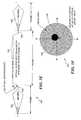
- a cut-away view in FIG. 2Aillustrates a variable radius or spiral scan mode of an optical fiber device 200 .
- the scan mode shown in this Figurecan be generated by driving an optical fiber 208 into a resonant (or near resonant) condition using a two axis piezoceramic tube actuator 206 .
- a plurality of light detectors 204are arrayed around single piezoceramic tube actuator 206 in a simple arrangement, to produce signals indicative of the light received from a ROI, which is not shown in this Figure.
- a similar array of concentrically arranged and spaced-apart optical fibers 202can convey light received at the distal end of the optical fibers from the ROI to light detectors (not shown) that are disposed at a proximal end of the optical fibers (e.g., outside the body of a patient).
- Piezoceramic tube actuator 206concentrically surrounds optical fiber 208 , and the optical fiber is tapered to a distal end 210 .
- This tube actuatorproduces a driving force corresponding to a harmonic of a natural resonant frequency of optical fiber 208 so that the distal end of the optical fiber moves in an orbit 212 having an actuation controlled radius.
- the distal end of the scanning optical fibercorresponds to an optical point source that can be focused onto an illumination plane (not shown) by adding an imaging lens system 214 .
- a major advantage of this embodimentis that it employs a single actuator and a waveguide that provide high resolution, directed illumination, and imaging within a relatively small diameter enclosure.
- a series of variable radii circlesare produced in a circular scan mode.
- the optical fibercan be driven in either mode during successive scanning frames.
- the optical fiberWhen driven in a spiral scan mode, the optical fiber produces a spiral scan in which the radius alternately increases and decreases.
- the radiusis increased in the desired pattern, and then the fiber is more rapidly returned to its centered position to begin the next frame.
- the distal end of optical fiber 208scans an ROI to image the region and also renders therapy and/or diagnostic functions over the ROI.
- the whirling motion of the cantilevered optical fiberis controllably driven larger or smaller in diameter by increasing or decreasing the voltage applied to the four individual quadrants of piezoceramic tube actuator 206 . Changes in the diameter of the scan can thus be made from one scanning frame to the next.
- a “propeller” scan mode 216is illustrated in FIG. 2B .
- the scanning optical fibermoves back and forth along different diameters of a circle, scanning the ROI.
- the rotation of the linear scancan be generated from the two-axis piezoceramic tube actuator or by simply rotating a single-axis actuator so that the axis of movement rotates in a corresponding manner about the longitudinal axis of the optical fiber.
- the propeller scan modecan be used in successive scanning frames, or can be used in combination with either the linear, elliptical, circular, or spiral scan modes in successive scanning frames.
- FIG. 2Can alternative beam scanning embodiment 220 of the optical fiber device is illustrated in FIG. 2C .
- This embodimentuses a combination of a microlens 228 at the distal fiber tip, and a scan lens system 238 .
- the use of microlens 228 on the distal end of optical fiber 226produces a PSF that is consistently small across a wide field of view (FOV).
- FOVwide field of view
- the addition of a microlens to the resonant cantilevered waveguide structurecreates a more complicated dynamic system than the previous point-source imaging embodiments shown in FIGS.
- Beam scanning embodiment 220includes a cylindrical supporting housing 222 in which is disposed a cylindrical actuator 224 of the piezoelectric or piezoceramic type that drives an optical fiber 226 to vibrate in a resonant 2-D scanning mode.
- Microlens 228is fabricated at the distal end of optical fiber 226 for the purpose of generally collimating a scanned beam of light.
- the scanned beam 230 of lightis focused by scan lens system 238 and describes an angle that is preferably greater than or equal to at least 40° relative to the longitudinal axis of the optical fiber and of cylindrical housing 222 .
- Light detectors 232are disposed as an outer annulus of a scan lens 233 and in a base 235 around cylindrical actuator 224 , which may be coated with a highly optical reflective material 237 (e.g., aluminum) to help channel the backscattered light to the detectors at high efficiencies.
- the light detectorsmay be optical sensors or may comprise the distal tips of collection optical fibers (with the option of including a microlens on each collection optical fiber for increased collection efficiency).
- a single light detectoris required to collect the backscattered scanned light, to generate a monochrome or black and white image.
- a simple method for generating a full-color imageis to use three light detectors, each covered with a different filter selected for blue, green, or red light transmission.
- Silicon-based semiconductor photodiodes(such as Si-PIN type) are preferred for visible and near IR light detection because of their high sensitivity, low cost, small size, high speed, and ruggedness.
- Photodiodes used routinely in the telecommunications industry, such as InGaAs material photodiodes,are preferred for embodiments of the present invention that use IR optical detection.
- the resolution of the integrated optical scanning techniquedoes not depend on size and number of light detectors, all available space at the distal end of the optical fiber assembly can be covered with light detectors for the purpose of increasing and discriminating between signal levels.
- the light detectorsare provided in stereo-pairs about the optic axis so that topographical features (e.g., shadows) of the ROI can be enhanced and glare from spectral reflections can be diminished.
- IR radiationis used in connection with visible light
- light detectors of different light-sensitive materialscan be used without filters (not shown).
- An alternative method for separating the spectral response of a light detector that is not filteredrequires synchronizing the detector signal in time with an appropriate illumination source having a pulsed output.
- the same visible light detectorcan be used without any filters if the RGB laser or other light sources are individually pulsed in rapid time series and in synchronicity with the processing of signals received from the light detectors.
- Leads 234extend from each of the light detectors to the proximal end of the optical fiber, which is external to the patient's body, to convey the electrical signals from the light detectors to the external instrumentation, as discussed above.
- Actuator 224is driven with an electrical signal supplied through leads 236 , and the characteristics and timing of the electrical signal determine the scan pattern, amplitude, and other parameters of the scanning pattern executed in each successive scanning frame.
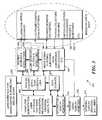
- FIG. 3illustrates a system 350 that shows how the signals produced by various components that are inside a patient's body are processed with external instrumentation and how signals used for controlling the system to vary the scanning parameter(s) in successive scanning frames are input to the components that are positioned inside the patient's body, (e.g., on an endoscope).
- system 350is thus divided into the components that remain external to the patient's body, and those which are used internally (i.e., the components within a dash line 352 ).
- a block 354lists the functional components disposed at the distal end of the scanning optical fiber system.
- these exemplary componentscan include illumination optics, one or more electromechanical scan actuator(s), one or more scanner control actuator(s), one or more scanner motion detector(s) for control of the scanner motion, photon detectors for imaging the ROI, and optionally, additional photon detectors for diagnostic purposes and for therapy and monitoring purposes—one or more of which can be implemented using the same scanning device by varying the parameters of the scanning that are employed during different scanning frames.
- illumination opticsone or more electromechanical scan actuator(s), one or more scanner control actuator(s), one or more scanner motion detector(s) for control of the scanner motion, photon detectors for imaging the ROI, and optionally, additional photon detectors for diagnostic purposes and for therapy and monitoring purposes—one or more of which can be implemented using the same scanning device by varying the parameters of the scanning that are employed during different scanning frames.
- the functional components actually required for a specific applicationmay be included.
- the additional functions besides imagingcan be diagnostic, or therapy, or a combination of these functions.
- the illumination optics and scanner(s)are supplied light from imaging sources and modulators as shown in a block 356 .
- Further details concerning several preferred embodiments of external light source systems for producing RGB, UV, IR, and/or high intensity light conveyed to the distal end of an optical fiber systemare either disclosed below or will be evident to a person of ordinary skill in this art.
- Scanner sensorscan be used for controlling the scanning and produce a signal that is fed back to the scanner actuators, illumination source, and modulators to implement the scanning control after signal processing in a block 360 .
- the sensorsmay simply be one or more temperature sensors, since temperature affects resonance and an open feedback system, based on initialization. Also, a temperature rise may occur due to the higher power therapy illumination transmitted through the system or indirectly as the result of thermal heat radiated back from the tissue.
- Block 360image signal filtering, buffering, scan conversion, amplification, and other processing functions are implemented using the electronic signals produced by the imaging photon detectors and for the other photon detectors employed for diagnosis/therapy, and monitoring purposes.
- Blocks 356 and 360are interconnected bi-directionally to convey signals that facilitate the functions performed by each respective block.
- each of these blocksis bi-directionally coupled in communication with a block 362 in which analog-to-digital (A/D) and digital-to-analog (D/A) converters are provided for processing signals that are supplied to a computer workstation user interface or other computing device employed for image acquisition, processing, for executing related programs, and for other functions.
- A/Danalog-to-digital
- D/Adigital-to-analog
- Control signals from the computer workstationare fed back to block 362 and converted into analog signals, where appropriate, for controlling or actuating each of the functions provided in blocks 356 , 358 , and 360 .
- the A/D converters and D/A converters within block 362are also coupled bi-directionally to a block 364 in which data storage is provided, and to a block 366 .
- Block 366represents a user interface for maneuvering, positioning, and stabilizing the end of the scanning optical fiber within a patient's body.
- Block 364the data storage is used for storing the image data produced by the detectors within a patient's body, and for storing other data related to the imaging and functions implemented by the scanning optical fiber.
- Block 364is also coupled bi-directionally to the computer workstation 368 and to interactive display monitor(s) in a block 370 .
- Block 370receives an input from block 360 , enabling images of the ROI to be displayed interactively.
- one or more passive video display monitorsmay be included within the system, as indicated in a block 372 .
- Other types of display devicesfor example, a head-mounted display (HMD) system, can also be provided, enabling medical personnel to view an ROI as a pseudo-stereo image.
- HMDhead-mounted display
- FIG. 4illustrates the different functions that can be carried out with the scanning device in a scanning system 460 , depending upon the instrumentation that is used.
- a single scanning waveguideis used for imaging, sampling diagnoses, and administering therapy, each function being done during different frames, by appropriately changing one or more parameters of the scanning process to enable the desired function to be achieved.
- different functionalitycan be provided. For example, instead of providing diagnostic capabilities, the scanning system can be readily modified by changing a scanning parameter and other operational aspects of the scanning system, to monitor the progress of the therapy applied with the scanning system.
- an interactive computer workstation 462enables medical practitioners to control the scanning optical fiber and to execute software algorithms used for imaging, diagnosis (e.g., by obtaining an optical biopsy), and administering therapy—all by the same scanning optical fiber during different scanning frames that are implemented with different scanning parameters.
- a high resolution color monitor 464receives signals from a scanning optical fiber 484 that are conveyed over an optical fiber system 488 to a distribution console 472 .
- Optional RGB detectorsmay be provided if not included internally within the patient's body adjacent to scanning optical fiber 484 .
- a region of interest (ROI) 486is scanned by the optical fiber to produce the high resolution color images displayed to a user.
- ROIregion of interest
- two cathode ray tube monitorsdisplay images using two different contrast modes to generate the images of the same object (e.g., images of tissue at the ROI).
- the same resonant driven scanning optical fibermay produce both a full-color optical image on one CRT and a grayscale fluorescence image on the other CRT monitor. If the optical properties of the excitation and signal do not overlap, then two or more images may be generated simultaneously. Otherwise, the two images are either captured in sequential frames or in alternating line sweeps of the fast resonant scanner.
- image contrast modesfull-color optical and fluorescence
- the light sourcesare shuttered or directly turned off/on, depending upon the frame being implement with the scanning device.
- the signals from the photon detectorsare recorded and displayed as separate images.
- a medical practitionercan find and positively identify small or pre-cancerous lesions that may or may not be visible on a standard white-light image produced during an imaging mode.
- one of the two displaysmight be a touch screen, or pad-, voice-, or joystick-controlled monitor that enables the medical practitioner to select (draw the outline) of an ROI for laser surgery. Since the image may be moving, the touch screen monitor will require the image to be captured and frozen in time. However, once this ROI is outlined, image segmentation and object recognition algorithms may be implemented to keep the ROI highlighted during real-time image acquisition and display.
- the touch screen monitorcan provide sidebar menus for the practitioner to set parameters for the laser therapies, such as power level and duration of laser radiation exposure.
- the second displaywould not provide interactivity, but is preferably a high resolution monitor displaying the real-time optical image in full-color or grayscale. If IR photon detectors are integrated into the endoscope, the high resolution display with pseudo-color will allow the practitioner to monitor the progress of laser therapies, such as tissue heating and/or tissue irradiation in laser surgery.
- the scanning optical fiberis positioned at a desired location within the patient's body, opposite ROI 486 , using guide wires or a cannula (not shown) and a manual controller that facilitates tip navigation and stabilization, as indicated in a block 466 .
- ROI 486optical biopsy “spots” 485 illustrate the spatial and temporal distribution of single-point spectral measurements to diagnose for disease. These spots are distributed much like the current practice of invasively taking tissue samples for in vitro biopsy analysis. Each spot may be analyzed spectroscopically during a frame cycle of the optical scanner, separating t 1 and t 2 by, for example, about 1/30 second.
- IR thermal photodetectorsand an optional temperature monitor
- IR thermal photodetectorsas indicated in a block 468 could be included for receiving IR signals from the ROI.
- electrical power for microsensors and control electronicsare provided, as indicated in a block 470 .
- the signals provided by the control electronicsenable amplitude and displacement control of the optical fiber when the actuator that causes it to scan is controlled by both electrical hardware and software within block 470 .
- a spectrophotometer and/or spectrum analyzer 474is included for diagnostic purposes, since the spectral composition of light received from ROI 486 and distribution of optical biopsy locations 485 can be used for screening and diagnosis for such diseases as cancer to a medical practitioner in evaluation of the condition of the ROI, based upon spectral photometric analysis.
- red, green, and blue light sources 476 , 478 , and 480are combined and the light that they produce is conveyed through the optical fiber system to scanning optical fiber 484 .
- the light source used for spectral analysismay be a high power pulse from one of the RGB light sources (e.g., lasers), or a secondary laser or white light source. Since signal strength, time, and illumination intensity are limiting, a repeated single-point spectroscopic method can be initially employed, using flash illumination.
- the same or a different high power laser source 482can be employed to administer therapy, such as PDT, the laser ablation of tumors, and other types of therapy rendered with a high intensity source.
- the scanning parameters associated with such therapywill clearly need to be different than those used for imaging and diagnosis. For example, the scan amplitude and scan frequency will likely be much less than used for imaging, to ensure that the therapeutic high intensity laser light is limited to the tissue needing it.
- a medical practitionernavigates and maneuvers the flexible single scanning optical fiber component to an appropriate region of a patient's body while watching the high resolution color monitor displaying the standard, full-color endoscopic image.
- the search for tumors and/or pre-cancerous lesionsbegins by watching the monitor.
- a second monitorincluded with spectrophotometer and spectrum analyzer 474 displays a fluorescence mapping in pseudo-color over a grayscale version of the endoscopic image.
- an ROIis found, such as abnormal appearing tissue, the flexible endoscope is mechanically stabilized. The ROI is centered within the FOV, then magnified using the multi-resolution capability provided by the present invention.
- the size of the ROI or tumoris estimated, and a pixel boundary is determined by image processing either the visible image or the diagnostic image and possibly, by implementing a range finding to the ROI from the distal end of the scanner.
- spectroscopic diagnosisis required, such as LIFS, the distribution of optical biopsy points is estimated along with illumination levels.
- the diagnostic measurementsare performed by delivering the illumination repeatedly over many imaging frames automatically. The user can cease the diagnosis or have the workstation continue to improve signal-to-noise ratio and/or density of sampling until a clear diagnosis can be made.
- the results of diagnosisis expected to be in real-time and overlaid on top of the standard image.
- a single-point or single-pixel optical biopsy proceduremay not have sufficient optical power or image stability to perform frame-sequential signal averaging.
- a single optical biopsy “spot”will be selected, close to the center of the imaging FOV. Because the amplitude-modulated resonant scanning for normal imaging can be interrupted between frames, the diagnostic frame can be a single beam of illumination that is “parked” for an arbitrary period of time. The duration of the single optical biopsy “spot” can be determined by the user or by the system, having determined that sufficient signal has been acquired for an accurate diagnosis.
- the single optical biopsy spotmay be enlarged slightly by non-resonant scanning of the illumination light or by resonant scanning in response to drive signals applied to the actuators that are significantly smaller in magnitude than those employed during the imaging frames.
- Exemplary drive signalsare illustrated in FIGS. 5A-5H , along with some resulting scan patterns.
- the diagnostic functionthat is implemented with the scanning optical fiber system (or other type of scanning device) can detect a fluorescence of tissue at a position in the region being scanned, which may be evidence of a physiological condition. Or the diagnostic function might determine either a fluorescent or phosphorescent lifetime at a desired position in the region.
- Other diagnostic proceduresthat can be performed include conducting a laser-induced fluorescence spectroscopic analysis at the desired position in the region being scanned, conducting a white light reflectance spectroscopic analysis at the desired position, and conducting a Raman spectroscopic analysis at the position.
- Diagnosismay include accurate mapping of distances and depths, for example, by implementing range finding between the endoscope and tissue for estimating size or coherence imaging, or optical coherence tomography line scans for estimating depth of structures within tissue, such as tumor penetration. Those of ordinary skill will readily understand how appropriate light sources and scanning parameters can be applied to achieve each of these diagnostic functions.
- optical therapyis warranted, such as PDT
- an optical radiation exposureis determined and programmed into the interactive computer workstation controlling the scanning optical system.
- the PDT treatmentis an optical scan of high intensity laser illumination typically by high power laser source 482 , pre-selected for the PDT fluorescent dye, and can be controlled using dichroic filters, attenuators, and electromechanical shutters.
- both fluorescence images and visible imagesare acquired during PDT treatment using the same scanning device, by controlling the scanning parameters to achieve the appropriate scanning for each functionality in different scanning frames.
- the medical practitionermonitors the progress of the PDT treatment by observing these acquired images on both displays.
- the dwell times for individual pixels within the image framemay be insufficient to cause the desired therapeutic effects, such as laser ablation or thermal necrosis, when optical illumination intensity is simply increased. Therefore, the resonant scanning used for imaging may need to be turned off or interrupted, and the illumination “parked” over a certain ROI for therapy.
- the ability to park the illumination at the central pixel in the imaging field on a frame-sequential basisenables the dwell time of light-tissue interaction to be arbitrary or selectively defined by the user and not dependent upon limitation of the imaging system. Long dwell times may be required for laser hole drilling or single point laser ablations.
- the holes being drilledmay be predetermined to fill an entire area, such as when a large hole is bored by making many smaller holes in a pattern.
- the ROIcan be re-imaged in a frame-sequential manner.
- Each holecan be enlarged slightly by scanning at a non-resonant frequently or by scanning at very low amplitudes at or near the resonant frequency used for imaging. By scanning a much smaller area than that covered by the imaging frame, the dwell times at each pixel position is increased by the slower translation of the scanned spot.
- Exemplary drive signalsare illustrated in FIGS. 6A-6D and 7 A- 7 F, along with resulting scan patterns.
- Various types of optical therapycan be delivered using the scanning device, by providing an appropriate intensity light source and controlling the scanning parameters of the scanning device drive signal to achieve a desired pattern and other appropriate characteristics.
- the control of this therapycan be monitored either by imaging between repeated does of therapy, or by providing a separate monitoring function, such as infrared thermal imaging or blood flow imaging frames.
- the scanning devicecan be used to deliver a laser illumination photoactivation by releasing a molecule, or a laser optoporation procedure, or a vision modification procedure, and then by switching parameters and the light source used, medical personnel can determine the efficacy of the therapy, assess any signs of damage, and/or determine if further therapy is needed.
- FIGS. 5A-5Hillustrate several examples of the different scanning parameters that be employed in successive scanning frames. All of FIGS. 5A-5H illustrate the exemplary case of a spiral scan of a resonant fiber scanner with the drive signals to the two-dimensional actuator for lateral vibration of the cantilevered optical fiber set to equal frequency and amplitude. However, only one axis of drive signal is shown in FIGS. 5A-5H , which is labeled the X-drive axis. Typically, the Y-drive axis is nearly identical in amplitude and frequency, but is phase-shifted to create a desired pattern, for example, by 90-degrees to generate a circular resonant motion.
- each successive scanning frame 502is identical, but the scanning device is stopped for an arbitrary or selected interval of time, depending on the function required of the resonant scanning device.
- the repeated scanning framesrepresent the continuous imaging mode of normal operation of a scanning fiber endoscope.
- each imaging framethere is a time that the resonant fiber scan is driven into an expanding spiral pattern, as identified by an expanding spiral duration 504 .
- a retrace time 506After full expansion of the spiral scan, there is a period of time for repositioning the fiber back to the starting position before another imaging frame, i.e., a retrace time 506 , and a minimum settling time 508 , which is used for settling the resonant amplitude to zero. All time intervals are selectively adjustable by the user (or automatically by the system) depending on the functions required of the scanning frames.
- the repeated imaging frame that is defined by expanding spiral duration (ESD) 504 , time to retrace 506 , and minimum settling time 508is identical with the first imaging frame illustrated as frame i.
- a subsequent imaging frameis indicated by i+1.
- settling time 508can be expanded in time arbitrarily for a diagnostic function during a frame i+2, as shown in FIG. 5A as a reference number 509 .
- This diagnostic functioncan maintain the fiber scanner in a stationary position for an arbitrary length of time to allow sufficient optical power to perform an optical biopsy diagnosis at a single location or “spot,” as defined earlier.
- the interrupted resonant fiber scanning for imagingis resumed in a subsequent frame i+3.
- the expanding spiral scan used for imagingis symmetrical about the origin of the X and Y drive axes, resulting in a circular two-dimensional scan pattern 510 shown in FIG. 5B .
- the three imaging frames i, i+1, and i+3 from FIG. 5Aeach scan a circular area 512 in FIG. 5B .
- the single optical biopsy “spot”is located at an origin or center 514 of circular area 512 . All representations of the 2-D scan pattern from successive imaging frames that are interrupted by frames employed for other carrying out functions assume that there is no motion other than the fiber scanning motion, i.e., that the endoscope remains stationary.
- a plurality of scanning frames 520is illustrated in which scanning frame 502 is followed by settling time 508 in which the scanning device is stopped, and the scanning device is next driven, as shown in a scanning frame 522 .
- scanning frame 522the scanning device is driven up to twice the maximum amplitude of frame 502 , but at a substantially lower frequency than in scanning frame 502 , and the duration of scanning frame 522 is longer than that of scanning frame 502 .
- the frequency within the imaging frameis at or near the resonance of the fiber scanner, while the frequency within the subsequent diagnostic frame is substantially less than the scanner resonance.
- a round imaged area 532 in a 2-D scan pattern 530 in FIG. 5Dis exactly the same as circular area 512 in FIG. 5B ; however, a single biopsy spot 534 in FIG. 5D is slightly enlarged by the non-resonant scanning, compared to circular area 512 from FIG. 5B .
- FIG. 5Ea plurality of scanning frames 540 is illustrated in which scanning frame 502 is followed by settling time 508 during which the scanning device is stopped before starting to drive the scanning device in a scanning frame 542 .
- scanning frame 542the scanning device is driven by the combination of both a periodic signal (AC-signal) at very small amplitude and having a steady-state offset (DC-offset) at large amplitude.
- AC-signala periodic signal
- DC-offsetsteady-state offset
- the small-amplitude periodic signal during the diagnostic frame in FIG. 5Eis at or near the resonant frequency, allowing mechanical amplification of motion.
- a resulting optical biopsy spot 554is enlarged and offset from the origin or the center of an imaged field 552 due to the applied DC-offset.
- the non-resonant DC-offsetcan also shift the single optical biopsy spot axially (or in depth), as well as laterally.
- the DC-offsetcan be applied to an actuator that shifts the point source closer to the lens system, which will increase the focal depth. For example all four quadrants (+X, ⁇ X, +Y, ⁇ Y) of the tube piezoceramic actuator can be activated equally to effectively enlarge the tube structure, by moving the fiber tip toward the lens system without displacing the point source laterally.
- Another actuator(not shown) can be activated with a DC-offset to optically zoom and change the depth of the scanned illumination plane and the location of the optical diagnosis.
- a plurality of scanning frames 560illustrates a series of alternating imaging frames with the scanning device operated at interrupted resonance (illustrated with the X-drive signals only).
- a drive signal 562 for frame igenerates a resonant fiber-scanned image that has twice the amplitude, but one-half the ESD as the resonant fiber-scanned image of frame i+1 that is produced with a drive signal 564 . Since both frames are imaging at or near the fiber scanner resonance frequency, the expanding spiral duration determines the number of scan lines (circles) within the imaged field.
- the maximum amplitude of the drive signaldetermines the maximum amplitude of the fiber scanner, which directly relates to the imaged field of view.
- a resulting image 572 from frame iwould be half the diameter of an image 574 from frame i+1 as shown in FIG. 5H .
- the image frame of larger field-of-view (frame i)would be displayed to the user across a larger display area than the image frame of smaller field-of-view (frame i+1), so in practice, two different displays will be used or the formatting of the images can be adjusted to accommodate the user's expectations.
- the use of continuously changing drive signals applied to a resonant optical scanner in a time seriesillustrates that the resulting two displayed images can be concurrently displayed to the user.
- a plurality of imaging framesare interrupted by both diagnostic and therapeutic frames in an illustrative example 600 of FIG. 6A .
- the X-drive signal over a series of five framesare shown for driving a resonant fiber scanner while the Y-drive signal is expected to appear similar, but 90-degrees out of phase (for spiral scanning).
- An initial frame 602is the standard imaging frame i that was represented in FIG. 5A .
- An expanding spiral duration 603 , a retrace time 604are shown, and a settling time 605 separate the imaging frame i from a subsequent diagnostic frame 606 , i.e., diagnostic frame i+1.
- the diagnostic frame (i+1)can be a fluorescence image that may require more light-tissue interaction dwell time per unit area than the imaging frame (i), which requires a ESD 607 .
- the duration of retrace time 608 and a setting time 609are expected to be the same as for the imaging frame, since the field of view is about the same (same maximum amplitude).
- a subsequent therapeutic frame (i+2)requires the longest light-tissue interaction dwell time per area, so an expanding spiral duration 611 is maximized, while a retrace time 612 and a settling time 613 can be equal to or shorter than previous frames having a larger FOV.
- the therapeutic frame (i+2)can be for photodynamic therapy, exciting the same fluorescent sensitizer that was imaged in the previous diagnostic frame (i+1), but at much higher power and over a smaller area.
- the following framerepresents a repeated diagnostic frame (i+3) like diagnostic frame 606 that images the same fluorescence emission spectrum from the previous diagnostic frame (i+1).
- the repeated fluorescence diagnosiscan give the user a measure of residual fluorescence activity, which may correlate to the prospect of repeating the photodynamic therapy.
- a final frame (i+4)(like initial frame 602 represents a series of repeated imaging frames. These exemplary sequential frames correspond to what is expected to a typical operation of an endoscope using the present approach.
- the 2-D scan patterns of the exemplary X-drive signals that result in imaging, diagnosis, and therapeutic frames in time sequential seriescan be superimposed, as illustrated in FIG. 6B .
- Superimposed spiral scan patterns 620are shown as the imaged area with a vertical line fill 622 , a fluorescence diagnosis area with a horizontal line fill 624 , and a smaller therapeutic PDT area (as dark fill) ( 626 ). Since no offset voltages were used in the drive signals, all scanning patterns are centered at the origin. Also, since both X and Y drive signals were assumed to be matched in frequency and amplitude, the scanning patterns are circularly symmetric.
- FIG. 6Cillustrates an exemplary set of consecutive frames of imaging, therapy, monitoring, and imaging 640 produced with the X-drive signal required for generating the resonant fiber scans.
- a first imaging frame (i) 602has an expanding spiral duration 603 , retrace time 604 and settling time 605 as shown in FIG. 6A .
- a subsequent therapeutic frame (i+1) 646provides a stationary or single point of therapy for an arbitrary amount of time. Long periods of light-tissue interaction are required for therapies such as thermal heating and thermal necrosis.
- a monitoring frame (i+2) 650which is employed to assess the tissue response to the optical therapy applied and to assess whether therapy should be repeated.
- the monitoring framecan use infrared imaging to assess the depth of damage, or thermal mapping to assess the temperature of the tissue.
- the series of framesends with a repeated imaging frame (i+3), which is identical to initial frame 602 .
- FIG. 6Dillustrates resulting 2-D scan patterns 660 produced from the X-drive signals of FIG. 6C . All three scan patterns of imaging, therapy, and monitoring are superimposed. An imaged area 662 is the largest circular area, while a therapeutic central spot 664 is disposed at the origin, since there was no scanning. A scan 666 for monitoring was at one-half the maximum drive amplitude of scan 662 for imaging, so the area is shown at one-half the diameter of scan 662 .
- the scanning signal that drives a scanning devicecan be driven in two orthogonal directions, i.e., in an X direction and a Y direction, as shown by input signal waveforms 700 and 715 , in FIG. 7A .
- Input signal waveform 700includes an initial frame (i) and a final (i+10) scanned image frame 701 , which are separated by nine separate therapeutic frames (i+1 through i+9) 702 through 710 .
- the X-drive signalis shifted by a DC-offset voltage indicated by the amplitude of the stepped voltage signal.
- Y-drive signal waveform 715includes an initial frame (i) and a final (i+10) imaging frame 716 separated by nine therapeutic frames (i+1 through i+9) 717 through 725 .
- a separate set of DC-offset voltages for the Y-drive signalproduce a central point and eight surrounding points of fixed-point illumination.
- the X and Y input signal waveforms 700 and 715represent the same total time interval. While the resonant scan frequency is the same in all the amplitude-modulated imaging scans, the Y-scan drive signal is shifted 90-degrees out of phase with the X-scan drive signal in input signal waveforms 700 and 715 to generate a spiral scan using a resonant fiber scanner.
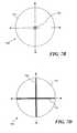
- Exemplary scan patterns 730 from waveforms in FIG. 7Aare shown in FIG. 7B .
- Nine therapeutic spots 732are shown superimposed on a circular imaged area 731 .
- nine smaller therapeutic spots 732 in FIG. 7Bare produced over a shorter duration of laser ablation resulting in hole drilling.
- the therapeutic hole drillingis shifted laterally in a times series by applying eight different non-resonant DC-offsets to the X and Y drive signals shown in FIG. 7A .
- the applied DC-offsetcan also be in the axial Z-direction, which would expand the hole depth more than the ablation area.
- two orthogonal diagnostic line scans 750 , and 760are introduced within a series of scanned imaging frames that have different exemplary scanner inputs (drive signals) for the X and Y directions.
- the first (i) and last (i+3) framesare resonant scanned image frames 701 and 716 for X and Y drive signals respectively.
- the next frame in time (i+1)is a resonant line scan along the horizontal or X axis that is repeated for an arbitrary time 752 .
- a corresponding Y axis drive signal 762 during this repeated horizontal line scanis zero, since no amplitude is required in the direction orthogonal to the X-axis.
- the subsequent frame (i+2)is a resonant line scan along the orthogonal vertical Y axis that is repeated for an arbitrary time 754 for the X-drive, and arbitrary time 764 for the Y-drive. Since the line scan is only along the vertical or Y axis, there is no amplitude during this frame (i+2) for the X-drive, but there is full amplitude for the Y-drive signal.
- Each of the linear scanning patterns(horizontal and vertical) are repeated resonant line scans for an arbitrary time period that can be defined by the diagnosis procedure being carried out. Since the scan pattern remains the same during each diagnostic period, the resulting diagnostic line scans in orthogonal directions are referred to as two frames (i+1) and (i+2).
- FIG. 7DThe 2-D scanning patterns of the imaging and diagnostic frames are illustrated in FIG. 7D .
- a round imaged area 772is centered at the origin of the vertical and horizontal axes.
- the two orthogonal linear scansare repeated along a horizontal axis 774 and a vertical axis 776 within the imaged circular area, since the maximum amplitudes of the resonant drive signals for imaging and diagnosis are the same.
- the repeated diagnostic line scancan have several functions. By scanning over the same area repeatedly, a weak diagnostic signal scan be averaged at each pixel to increase the signal-to-noise ratio. Alternately, the light source can be tuned or filtered to different spectral regions of scanned illumination to conduct multi-spectral or hyper-spectral analysis. Additionally, the focal depth may be changed over the repeated line scans to measure diagnostic optical fluorescence or backscattered light (optical coherent tomography signal) over increasing depth to create a cross-sectional view or slice through the tissue structures.
- FIGS. 7E and 7Fillustrate a plurality of resonant scanned imaging frames that are interrupted with one or more frames for diagnosis, therapy, and/or monitoring and which have a scan area that is selectively determined in size, in order to match the desire of the user or to match the geometry of the ROI.
- FIG. 7Ethe different inputs to the X-drive (solid line) and Y-drive (dashed line) signals 780 are illustrated as described below, using a resonant fiber scanner with spiral scanning pattern.
- First (i) and last (i+2) imaging frames 782represent continuous imaging before and after either a diagnosis, therapy, and/or monitoring frame (i+1) 784 .
- Frame (i+1) 784has a maximum X-drive signal amplitude 786 that is twice a Y-drive signal amplitude 788 .
- the X-drive signal for the amplitude-modulated resonant scanningis over twice the duration but less than the maximum amplitude of the imaging frame.
- FIG. 7Fthe resulting 2-D scan patterns are illustrated as a superposition 790 .
- a circular imaged area 792is centered about the origin, while an elliptical area 794 that defines a diagnostic, therapeutic, or monitored region is smaller, with its greatest dimension along the X-axis.
- the elliptical areais centered about the origin, since no offset voltages were applied in this example.
- interrupted resonance scanningfor the purpose of varying the implementation of a function such as imaging, diagnosis, therapy, and monitoring in a frame sequential manner were all illustrated using a resonant fiber scanner and mostly in a spiral scanning mode of operation.
- Normal operation of the spiral scanning framecan eliminate the fast retrace and settling time for the resonant fiber scanner and operate with a continuous triangle wave for the amplitude modulation waveform that may never go to zero amplitude of resonant fiber motion (for example, see “Modeling and Control of the Resonant Fiber Scanner for Laser Scanning Display or Acquisition,” Smithwick et al., page 1455, SID '03 Digest, (2003), which describes the use of triangle waves with and without feedback control).
- scanning patternscan be implemented with a scanning fiber with minor modifications, such as Lissajous scan patterns (for example, see “A Miniature Head-Mounted Two-Photon Microscope: High-Resolution Brain Imaging in Freely Moving Animals,” Helmchen et al, Neuron, Vol. 31, 903-912, Sep. 27, 2001, Copyright 2001 by Cell Press).
- the optical scannercan be used for illumination only, illumination and detection, or detection of optical signals only.
- FIG. 8illustrates a first embodiment of an exemplary scanning device 800 for use in an endoscope that uses a moving micro-electro-mechanical system (MEMS) reflective surface 818 for scanning a region 840 .
- a single mode optical fiber 810conveys an optical signal 816 , producing an expanding beam, for example, with a numerical aperture approximately equal to 0.11.
- a vertical drive actuator 812 and a horizontal drive actuator 814bi-axially move the reflective surface in the X and Y directions relative to a centerline 838 .
- An orifice 820is formed in the MEMS reflective surface to enable the expanding light beam to pass through the MEMS reflective surface along a path 826 toward a fixed convex mirror 824 .
- MEMS reflective surfaceis not required to be concave (as shown in the Figure), but can instead be flat so that it does not provide any optical power for focusing the light beam.
- the MEMS mirror surfacecan be manufactured to be varied dynamically (for example, see Yuhe Shao et al., “MEMS Three-dimensional scan mirror, In MOEMS Display and Imaging Systems II,” edited by Hakan Urey et al., Proceedings of the SPIE Vol. 5348: 175-183, 2004).
- the optical systemcan still converge the light beam to a desired focus at point 836 that is distal of the distal end of the endoscope.
- a planar (rather than a concave) MEMS reflective surfacewould actually be easier to manufacture at a high optical quality.
- the bi-axial scanning of the MEMS reflective surface necessary to provide a sufficient FOV for an endoscopewould likely require the MEMS reflective surface to move in a resonant or near resonant motion.
- a non-resonant movement of the MEMS reflective surfacemay be sufficient for a microscopic FOV, (e.g., less than 1 mm in diameter).
- FIGS. 9A and 9BA second exemplary embodiment of a moving mirror scanning device 900 that can be used, for example, in an endoscope, is illustrated in FIGS. 9A and 9B .
- Scanning device 900differs from scanning device 800 , because it uses two separate reflective surfaces for the two orthogonal axes, one for the X axis and one for the Y axis. Each reflective surface is thus driven to scan only in regard to one axis.
- a resonant drive 902will be used to drive a reflective surface 904 to move back and forth in the horizontal direction. Most likely, resonant drive 902 and scanning reflective surface 904 will comprise a resonant MEMS scanner.
- a single mode optical fiber 910conveys a light beam 912 toward a flat reflective surface 906 that serves to vertically scan the beam and is mounted on a shaft 908 a .
- Shaft 908 ais driven to oscillate back and forth by a vertical drive 908 that, being smaller than the horizontal scanner, operates at a resonant or near resonant state with a fast fly back, (e.g., at the frame rate of the raster scan).
- the light beamis reflected from flat reflective surface 906 along a path 914 toward horizontally scanning reflective surface 904 and is reflected thereby along a path 916 and through scan lenses 918 and 920 .
- These scan lensesfocus the light beam to a point 922 on a region 940 , so that the point scans over the region in a desired pattern determined by the signal that drives the vertical and horizontal scanners.
- Scanning device 900is illustrated as having a non-confocal geometry.
- Light from the region resulting from the scanningtravels back through scan lenses 920 and 918 , along an exemplary path 924 , and into an optional collection optical fibers 926 , 928 , and 930 , which may be provided with red, green, and blue filters, or with other waveband filtering.
- the optional collection optical fiberscan be placed either outside the scanning device portion of the endoscope that includes the lenses, or may surround the MEMS reflective surface comprising the vertical scanner, as shown.
- a single mode RGB optical fiber 910as well as other optional optical fibers 932 , 934 , and 936 can be provided to implement other functions.
- optional optical fiber 936can be a single mode optical fiber that conveys a high intensity light beam produced by a high power laser for rendering therapy to a desired portion of region 940 , using the two scanners.
- FIG. 10An embodiment of a small-core optical fiber that has been conditioned to increase the optical damage threshold is shown in FIG. 10 .
- light 1010 that is to be conducted through an optical fiber 1050is first passed through a coupling lens 1020 to focus the energy.
- An optional aperture 1030may be used to control the diameter of the light beam as it converges onto the small core of optical fiber 1050 .
- a precisely controlled diameterwill ensure that there is minimal stray light that could be absorbed and lead to optical damage.
- On the front face or proximal end of the small-core optical fiber 1050is mounted an end cap 1040 .
- End cap 1040is made of the same or a material similar to that of the core of the optical fiber and is essentially just a larger diameter component that reduces the intensity of light deliver to the proximal interface. Cap 1040 enables minimal absorption to take place at an interface 1060 and eliminates the possibility of adsorbed contaminates, where the optical intensity is the greatest, by providing a continuous medium for the light to propagate locally. Since end cap 1040 and optical fiber 1050 are made of the same or similar material, interface 1060 will exist only symbolically and not physically, providing that a high quality splicing or fusing process has been used for joining end cap 1040 and optical fiber 1050 into one continuous unencumbered medium. The interface between air and the medium will effectively be moved to an interface 1070 disposed at the proximal end of the end cap.
- Interface 1070can be conditioned using a mechanical or optical polish to reduce the amount of optical absorption at this interface.
- a mechanical polishinvolves grinding the surface of interface 1070 with a successively finer abrasives until the surface is free from scratches, pits, etc.
- An optical polishinvolves irradiating the surface of interface 1070 with a high power infrared light sourced so that a plasma forms for a short time on the surface. When the plasma cools and the material resets, any residual scratches, pits, etc. will have been removed.
- the surface of interface 1070can also be coated to minimize reflections at the selected optical frequencies.
- light conductive optical fiber 1050with end cap 1040 , focusing lens 1020 , and optional aperture 1030 , can be hermetically sealed within an internal enclosure 1080 so that no contaminants are allowed to form on the surface of interface 1070 .
- An X Y Z micropositioning system 1090can be added to the optical fiber plus end-cap system to provide compensation for any thermal drift of position due to the transient introduction of high power optical energy used for therapy.
Landscapes
- Health & Medical Sciences (AREA)
- Life Sciences & Earth Sciences (AREA)
- Physics & Mathematics (AREA)
- Surgery (AREA)
- Optics & Photonics (AREA)
- Medical Informatics (AREA)
- Animal Behavior & Ethology (AREA)
- Radiology & Medical Imaging (AREA)
- Nuclear Medicine, Radiotherapy & Molecular Imaging (AREA)
- Engineering & Computer Science (AREA)
- Biomedical Technology (AREA)
- Heart & Thoracic Surgery (AREA)
- Biophysics (AREA)
- Molecular Biology (AREA)
- Pathology (AREA)
- General Health & Medical Sciences (AREA)
- Public Health (AREA)
- Veterinary Medicine (AREA)
- General Physics & Mathematics (AREA)
- Astronomy & Astrophysics (AREA)
- Laser Surgery Devices (AREA)
- Endoscopes (AREA)
- Mechanical Optical Scanning Systems (AREA)
- Radiation-Therapy Devices (AREA)
Abstract
Description
Claims (39)
Applications Claiming Priority (1)
| Application Number | Priority Date | Filing Date | Title |
|---|---|---|---|
| PCT/US2005/042577WO2007067163A1 (en) | 2005-11-23 | 2005-11-23 | Scanning beam with variable sequential framing using interrupted scanning resonance |
Publications (2)
| Publication Number | Publication Date |
|---|---|
| US20090028407A1 US20090028407A1 (en) | 2009-01-29 |
| US8537203B2true US8537203B2 (en) | 2013-09-17 |
Family
ID=38123184
Family Applications (1)
| Application Number | Title | Priority Date | Filing Date |
|---|---|---|---|
| US12/088,057Active2029-02-20US8537203B2 (en) | 2005-11-23 | 2005-11-23 | Scanning beam with variable sequential framing using interrupted scanning resonance |
Country Status (4)
| Country | Link |
|---|---|
| US (1) | US8537203B2 (en) |
| EP (1) | EP1954193B1 (en) |
| JP (1) | JP2009516568A (en) |
| WO (1) | WO2007067163A1 (en) |
Cited By (55)
| Publication number | Priority date | Publication date | Assignee | Title |
|---|---|---|---|---|
| US20080275305A1 (en)* | 2007-05-01 | 2008-11-06 | Ethicon Endo-Surgery, Inc. | Medical scanned beam imager and components associated therewith |
| US20110211104A1 (en)* | 2008-11-14 | 2011-09-01 | Koninklijke Philips Electronics N.V. | Optical fiber scanning probe |
| US20120265061A1 (en)* | 2011-04-13 | 2012-10-18 | St. Jude Medical, Inc. | High speed elastographic property mapping of lumens utilizing micropalpation delivered from an oct-equipped catheter tip |
| JP2012203038A (en)* | 2011-03-23 | 2012-10-22 | Olympus Corp | Wide-angle light detection member and scan type observation device using the same |
| US20130162775A1 (en)* | 2011-11-29 | 2013-06-27 | Harald Baumann | Apparatus and method for endoscopic 3D data Collection |
| US20140073950A1 (en)* | 2012-05-31 | 2014-03-13 | Olympus Medical Systems Corp. | Scanning endoscopic device and method of decreasing directivity of beam light in scanning endoscopic device |
| US20140255985A1 (en)* | 2011-01-21 | 2014-09-11 | The Regents Of The University Of Michigan | Two-photon endoscopic scanning assembly for inflammatory disease detection |
| US20150126858A1 (en)* | 2013-11-06 | 2015-05-07 | Korea Advanced Institute Of Science And Technology | Fiber scanning optical probe and medical imaging apparatus including the same |
| US20150305811A1 (en)* | 2012-11-09 | 2015-10-29 | Biolitec Pharma Marketing Ltd. | Device and method for laser treatments |
| US9343489B2 (en) | 2011-05-12 | 2016-05-17 | DePuy Synthes Products, Inc. | Image sensor for endoscopic use |
| US9462234B2 (en) | 2012-07-26 | 2016-10-04 | DePuy Synthes Products, Inc. | Camera system with minimal area monolithic CMOS image sensor |
| US9498300B1 (en)* | 2015-07-30 | 2016-11-22 | Novartis Ag | Communication system for surgical devices |
| US9516239B2 (en) | 2012-07-26 | 2016-12-06 | DePuy Synthes Products, Inc. | YCBCR pulsed illumination scheme in a light deficient environment |
| US9641815B2 (en) | 2013-03-15 | 2017-05-02 | DePuy Synthes Products, Inc. | Super resolution and color motion artifact correction in a pulsed color imaging system |
| US9704266B2 (en) | 2014-12-11 | 2017-07-11 | Rdi, Llc | Non-contacting monitor for bridges and civil structures |
| US20170196444A1 (en)* | 2014-05-30 | 2017-07-13 | Korea Institute Of Machinery & Materials | Laser induced breakdown spectroscopy device and medical diagnostic device using same |
| US20170209709A1 (en)* | 2016-09-09 | 2017-07-27 | Shenzhen Peninsula Medical Co., Ltd. | Light treatment apparatus |
| US9777913B2 (en) | 2013-03-15 | 2017-10-03 | DePuy Synthes Products, Inc. | Controlling the integral light energy of a laser pulse |
| US9980789B2 (en) | 2014-12-05 | 2018-05-29 | Convergent Dental, Inc. | System and methods for alignment of a laser beam |
| US20180180875A1 (en)* | 2016-12-23 | 2018-06-28 | Magic Leap, Inc. | Microstructured fiber optic oscillator and waveguide for fiber scanner |
| US10062411B2 (en) | 2014-12-11 | 2018-08-28 | Jeffrey R. Hay | Apparatus and method for visualizing periodic motions in mechanical components |
| US10084944B2 (en) | 2014-03-21 | 2018-09-25 | DePuy Synthes Products, Inc. | Card edge connector for an imaging sensor |
| US10251530B2 (en) | 2013-03-15 | 2019-04-09 | DePuy Synthes Products, Inc. | Scope sensing in a light controlled environment |
| US10376147B2 (en) | 2012-12-05 | 2019-08-13 | AccuVeiw, Inc. | System and method for multi-color laser imaging and ablation of cancer cells using fluorescence |
| US10517469B2 (en) | 2013-03-15 | 2019-12-31 | DePuy Synthes Products, Inc. | Image sensor synchronization without input clock and data transmission clock |
| US10568496B2 (en) | 2012-07-26 | 2020-02-25 | DePuy Synthes Products, Inc. | Continuous video in a light deficient environment |
| US10580119B2 (en) | 2007-06-28 | 2020-03-03 | Accuvein, Inc. | Automatic alignment of a contrast enhancement system |
| US10750933B2 (en) | 2013-03-15 | 2020-08-25 | DePuy Synthes Products, Inc. | Minimize image sensor I/O and conductor counts in endoscope applications |
| US10813588B2 (en) | 2006-01-10 | 2020-10-27 | Accuvein, Inc. | Micro vein enhancer |
| US11047671B1 (en) | 2020-01-30 | 2021-06-29 | Veravanti Inc. | Forward looking RGB/optical coherence tomography duplex imager |
| US11051697B2 (en) | 2006-06-29 | 2021-07-06 | Accuvein, Inc. | Multispectral detection and presentation of an object's characteristics |
| US11051755B2 (en) | 2006-06-29 | 2021-07-06 | Accuvein, Inc. | Scanned laser vein contrast enhancer using a retro collective mirror |
| US11109806B2 (en) | 2006-01-10 | 2021-09-07 | Accuvein, Inc. | Three dimensional imaging of veins |
| US11122968B2 (en)* | 2019-06-20 | 2021-09-21 | Cilag Gmbh International | Optical fiber waveguide in an endoscopic system for hyperspectral imaging |
| US20210356737A1 (en)* | 2016-12-22 | 2021-11-18 | Magic Leap, Inc. | Methods and systems for multi-element linkage for fiber scanning display |
| US11191482B2 (en) | 2006-01-10 | 2021-12-07 | Accuvein, Inc. | Scanned laser vein contrast enhancer imaging in an alternating frame mode |
| US11213194B2 (en) | 2019-06-20 | 2022-01-04 | Cilag Gmbh International | Optical fiber waveguide in an endoscopic system for hyperspectral, fluorescence, and laser mapping imaging |
| US11253198B2 (en) | 2006-01-10 | 2022-02-22 | Accuvein, Inc. | Stand-mounted scanned laser vein contrast enhancer |
| US11278240B2 (en) | 2006-01-10 | 2022-03-22 | Accuvein, Inc. | Trigger-actuated laser vein contrast enhancer |
| US11282213B1 (en) | 2020-06-24 | 2022-03-22 | Rdi Technologies, Inc. | Enhanced analysis techniques using composite frequency spectrum data |
| US11322182B1 (en) | 2020-09-28 | 2022-05-03 | Rdi Technologies, Inc. | Enhanced visualization techniques using reconstructed time waveforms |
| US11357449B2 (en) | 2006-01-10 | 2022-06-14 | Accuvein, Inc. | Micro vein enhancer for hands-free imaging for a venipuncture procedure |
| US11373317B1 (en) | 2020-01-24 | 2022-06-28 | Rdi Technologies, Inc. | Measuring the speed of rotation or reciprocation of a mechanical component using one or more cameras |
| US11375886B2 (en) | 2019-06-20 | 2022-07-05 | Cilag Gmbh International | Optical fiber waveguide in an endoscopic system for laser mapping imaging |
| US11399768B2 (en) | 2006-01-10 | 2022-08-02 | Accuvein, Inc. | Scanned laser vein contrast enhancer utilizing surface topology |
| US11423551B1 (en) | 2018-10-17 | 2022-08-23 | Rdi Technologies, Inc. | Enhanced presentation methods for visualizing motion of physical structures and machinery |
| US11510617B2 (en) | 2012-08-02 | 2022-11-29 | Accuvein, Inc. | Device for detecting and illuminating the vasculature using an FPGA |
| US11642080B2 (en) | 2006-01-10 | 2023-05-09 | Accuvein, Inc. | Portable hand-held vein-image-enhancing device |
| USD998152S1 (en) | 2010-07-22 | 2023-09-05 | Accuvein, Inc. | Vein imager cradle |
| USD999379S1 (en) | 2010-07-22 | 2023-09-19 | Accuvein, Inc. | Vein imager and cradle in combination |
| US12048560B2 (en) | 2006-01-10 | 2024-07-30 | Accuvein, Inc. | Vein scanner configured for single-handed lifting and use |
| US12295744B2 (en) | 2006-01-10 | 2025-05-13 | Accuvein, Inc. | Micro vein enhancer with two lasers and two optical detectors configured for removing surface topology |
| US12300273B2 (en) | 2014-12-11 | 2025-05-13 | Rdi Technologies, Inc. | Apparatus and method for visualizing periodic motions in mechanical components |
| US12385733B2 (en) | 2020-01-30 | 2025-08-12 | Soham Inc. | Synchronizing an optical coherence tomography system |
| US12408865B2 (en) | 2006-01-10 | 2025-09-09 | Accuvein Inc. | Vein imaging device with differential image resolution at the center and the extremities of the vein image |
Families Citing this family (136)
| Publication number | Priority date | Publication date | Assignee | Title |
|---|---|---|---|---|
| US8797392B2 (en)* | 2005-01-05 | 2014-08-05 | Avantis Medical Sytems, Inc. | Endoscope assembly with a polarizing filter |
| US8872906B2 (en)* | 2005-01-05 | 2014-10-28 | Avantis Medical Systems, Inc. | Endoscope assembly with a polarizing filter |
| US20060149129A1 (en)* | 2005-01-05 | 2006-07-06 | Watts H D | Catheter with multiple visual elements |
| WO2006119200A2 (en)* | 2005-04-29 | 2006-11-09 | The Board Of Trustees Of The Leland Stanford Junior University | High-sensitivity fiber-compatible optical acoustic sensor |
| WO2007087421A2 (en) | 2006-01-23 | 2007-08-02 | Avantis Medical Systems, Inc. | Endoscope |
| US7881565B2 (en) | 2006-05-04 | 2011-02-01 | The Board Of Trustees Of The Leland Stanford Junior University | Device and method using asymmetric optical resonances |
| EP2023795A2 (en) | 2006-05-19 | 2009-02-18 | Avantis Medical Systems, Inc. | Device and method for reducing effects of video artifacts |
| JP4849985B2 (en)* | 2006-07-21 | 2012-01-11 | 富士フイルム株式会社 | Electronic endoscope system |
| US9079762B2 (en) | 2006-09-22 | 2015-07-14 | Ethicon Endo-Surgery, Inc. | Micro-electromechanical device |
| US7561317B2 (en) | 2006-11-03 | 2009-07-14 | Ethicon Endo-Surgery, Inc. | Resonant Fourier scanning |
| EP2104842B1 (en) | 2007-01-09 | 2011-09-07 | The Board of Trustees of The Leland Stanford Junior University | Fabry-perot acoustic sensor and corresponding manufacturing method |
| US7589316B2 (en) | 2007-01-18 | 2009-09-15 | Ethicon Endo-Surgery, Inc. | Scanning beam imaging with adjustable detector sensitivity or gain |
| US8064666B2 (en) | 2007-04-10 | 2011-11-22 | Avantis Medical Systems, Inc. | Method and device for examining or imaging an interior surface of a cavity |
| US7558455B2 (en) | 2007-06-29 | 2009-07-07 | Ethicon Endo-Surgery, Inc | Receiver aperture broadening for scanned beam imaging |
| US9125552B2 (en)* | 2007-07-31 | 2015-09-08 | Ethicon Endo-Surgery, Inc. | Optical scanning module and means for attaching the module to medical instruments for introducing the module into the anatomy |
| US7522813B1 (en)* | 2007-10-04 | 2009-04-21 | University Of Washington | Reducing distortion in scanning fiber devices |
| EP2225699A1 (en)* | 2007-11-27 | 2010-09-08 | University of Washington | Eliminating illumination crosstalk while imaging using multiple imaging devices |
| US8050520B2 (en) | 2008-03-27 | 2011-11-01 | Ethicon Endo-Surgery, Inc. | Method for creating a pixel image from sampled data of a scanned beam imager |
| US9788790B2 (en) | 2009-05-28 | 2017-10-17 | Avinger, Inc. | Optical coherence tomography for biological imaging |
| US8062316B2 (en) | 2008-04-23 | 2011-11-22 | Avinger, Inc. | Catheter system and method for boring through blocked vascular passages |
| US9125562B2 (en)* | 2009-07-01 | 2015-09-08 | Avinger, Inc. | Catheter-based off-axis optical coherence tomography imaging system |
| US8696695B2 (en) | 2009-04-28 | 2014-04-15 | Avinger, Inc. | Guidewire positioning catheter |
| US8332014B2 (en) | 2008-04-25 | 2012-12-11 | Ethicon Endo-Surgery, Inc. | Scanned beam device and method using same which measures the reflectance of patient tissue |
| JP2010113309A (en)* | 2008-11-10 | 2010-05-20 | Hoya Corp | Optical scanning type endoscope apparatus, optical scanning type endoscope, optical scanning type endoscope processor |
| JP2010113312A (en)* | 2008-11-10 | 2010-05-20 | Hoya Corp | Endoscope apparatus and endoscope processor |
| JP5210823B2 (en)* | 2008-11-19 | 2013-06-12 | Hoya株式会社 | Optical scanning endoscope, optical scanning endoscope processor, and optical scanning endoscope apparatus |
| JP5342869B2 (en)* | 2008-12-22 | 2013-11-13 | Hoya株式会社 | Endoscope apparatus, endoscope illumination apparatus, image forming apparatus, operation method of endoscope illumination apparatus, and operation method of image formation apparatus |
| JP2010172638A (en)* | 2009-02-02 | 2010-08-12 | Olympus Corp | Imaging device, endoscope, and electronic equipment |
| JP5606720B2 (en)* | 2009-03-04 | 2014-10-15 | オリンパス株式会社 | Photodetector |
| US8457716B2 (en)* | 2009-05-04 | 2013-06-04 | Covidien Lp | Time of flight based tracheal tube placement system and method |
| JP5498728B2 (en)* | 2009-06-09 | 2014-05-21 | Hoya株式会社 | Medical observation system |
| WO2011003006A2 (en) | 2009-07-01 | 2011-01-06 | Avinger, Inc. | Atherectomy catheter with laterally-displaceable tip |
| US8803962B2 (en)* | 2009-09-30 | 2014-08-12 | Boston Scientific Scimed, Inc. | System and method for imaging during a medical procedure |
| WO2011072068A2 (en) | 2009-12-08 | 2011-06-16 | Avinger, Inc. | Devices and methods for predicting and preventing restenosis |
| JP2011125404A (en)* | 2009-12-15 | 2011-06-30 | Olympus Corp | Light control device, control device, optical scope, and optical scan type optical device |
| CA2793452C (en) | 2010-03-15 | 2018-09-11 | The Board Of Trustees Of The Leland Stanford Junior University | Optical-fiber-compatible acoustic sensor |
| US11382653B2 (en) | 2010-07-01 | 2022-07-12 | Avinger, Inc. | Atherectomy catheter |
| WO2014039096A1 (en) | 2012-09-06 | 2014-03-13 | Avinger, Inc. | Re-entry stylet for catheter |
| US9345510B2 (en) | 2010-07-01 | 2016-05-24 | Avinger, Inc. | Atherectomy catheters with longitudinally displaceable drive shafts |
| US10548478B2 (en) | 2010-07-01 | 2020-02-04 | Avinger, Inc. | Balloon atherectomy catheters with imaging |
| DE102010033423A1 (en)* | 2010-08-04 | 2012-02-09 | Karl Storz Gmbh & Co. Kg | Endoscope with adjustable viewing direction |
| JP5492030B2 (en)* | 2010-08-31 | 2014-05-14 | 富士フイルム株式会社 | Image pickup display device and method of operating the same |
| EP3148016B1 (en)* | 2010-11-23 | 2018-02-28 | IPG Photonics Corporation | Laser process head |
| US8900126B2 (en) | 2011-03-23 | 2014-12-02 | United Sciences, Llc | Optical scanning device |
| EP2691038B1 (en) | 2011-03-28 | 2016-07-20 | Avinger, Inc. | Occlusion-crossing devices, imaging, and atherectomy devices |
| US9949754B2 (en) | 2011-03-28 | 2018-04-24 | Avinger, Inc. | Occlusion-crossing devices |
| JP5274726B2 (en)* | 2011-03-31 | 2013-08-28 | オリンパスメディカルシステムズ株式会社 | Scanning endoscope device |
| WO2012132750A1 (en)* | 2011-03-31 | 2012-10-04 | オリンパスメディカルシステムズ株式会社 | Scanning endoscope |
| JP2012237595A (en)* | 2011-05-10 | 2012-12-06 | Sumitomo Electric Ind Ltd | Optical tomography device |
| US9095414B2 (en)* | 2011-06-24 | 2015-08-04 | The Regents Of The University Of California | Nonlinear optical photodynamic therapy (NLO-PDT) of the cornea |
| JP2013017056A (en)* | 2011-07-04 | 2013-01-24 | Toshiba Corp | Image processing system, image processing method, and medical image diagnostic device |
| EP3653151A1 (en) | 2011-10-17 | 2020-05-20 | Avinger, Inc. | Atherectomy catheters and non-contact actuation mechanism for catheters |
| JP5776501B2 (en)* | 2011-11-10 | 2015-09-09 | コニカミノルタ株式会社 | Probe system |
| US9345406B2 (en) | 2011-11-11 | 2016-05-24 | Avinger, Inc. | Occlusion-crossing devices, atherectomy devices, and imaging |
| TW201329509A (en)* | 2012-01-10 | 2013-07-16 | Walsin Lihwa Corp | 3D scan device and 3D scan method thereof |
| JP5363688B1 (en)* | 2012-01-11 | 2013-12-11 | オリンパスメディカルシステムズ株式会社 | Light irradiation apparatus, scanning endoscope apparatus, method for manufacturing light irradiation apparatus, and method for manufacturing scanning endoscope |
| US8900125B2 (en)* | 2012-03-12 | 2014-12-02 | United Sciences, Llc | Otoscanning with 3D modeling |
| WO2013172970A1 (en) | 2012-05-14 | 2013-11-21 | Avinger, Inc. | Atherectomy catheters with imaging |
| US9557156B2 (en) | 2012-05-14 | 2017-01-31 | Avinger, Inc. | Optical coherence tomography with graded index fiber for biological imaging |
| EP2849660B1 (en) | 2012-05-14 | 2021-08-25 | Avinger, Inc. | Atherectomy catheter drive assemblies |
| JP2013244045A (en)* | 2012-05-23 | 2013-12-09 | Olympus Corp | Scanning endoscope apparatus |
| US20130322490A1 (en)* | 2012-05-31 | 2013-12-05 | Kidde Technologies, Inc. | Optical fiber sensing system |
| EP2875394B1 (en)* | 2012-07-17 | 2024-09-11 | Ecole Polytechnique Fédérale de Lausanne (EPFL) | Reflective optical objective |
| CN103997944B (en)* | 2012-09-03 | 2016-04-13 | 奥林巴斯株式会社 | Sweep type endoscopic system |
| US11284916B2 (en) | 2012-09-06 | 2022-03-29 | Avinger, Inc. | Atherectomy catheters and occlusion crossing devices |
| US9498247B2 (en) | 2014-02-06 | 2016-11-22 | Avinger, Inc. | Atherectomy catheters and occlusion crossing devices |
| JP5639310B2 (en) | 2012-10-22 | 2014-12-10 | オリンパスメディカルシステムズ株式会社 | Scanning endoscope system |
| JP5702023B2 (en)* | 2012-10-22 | 2015-04-15 | オリンパスメディカルシステムズ株式会社 | Scanning endoscope system and method of operating scanning endoscope system |
| EP2910175A4 (en)* | 2012-12-04 | 2016-06-01 | Olympus Corp | Scanning endoscope system |
| EP3865921A1 (en)* | 2013-01-15 | 2021-08-18 | Magic Leap, Inc. | Ultra-high resolution scanning fiber display |
| JP6128873B2 (en)* | 2013-02-06 | 2017-05-17 | オリンパス株式会社 | Laser therapy device |
| US20140273184A1 (en)* | 2013-03-14 | 2014-09-18 | Inspirotec Llc | Electrokinetic devices and methods for capturing assayable agents |
| CN105228514B (en) | 2013-03-15 | 2019-01-22 | 阿维格公司 | Optical Pressure Sensor Assembly |
| US11096717B2 (en) | 2013-03-15 | 2021-08-24 | Avinger, Inc. | Tissue collection device for catheter |
| WO2014143064A1 (en) | 2013-03-15 | 2014-09-18 | Avinger, Inc. | Chronic total occlusion crossing devices with imaging |
| WO2014188718A1 (en)* | 2013-05-21 | 2014-11-27 | オリンパス株式会社 | Optical scanning device and method for scanning light beam |
| EP3019096B1 (en) | 2013-07-08 | 2023-07-05 | Avinger, Inc. | System for identification of elastic lamina to guide interventional therapy |
| DE102013019348A1 (en)* | 2013-08-15 | 2015-02-19 | Carl Zeiss Microscopy Gmbh | High-resolution scanning microscopy |
| DE102013019347A1 (en)* | 2013-08-15 | 2015-02-19 | Carl Zeiss Microscopy Gmbh | High-resolution scanning microscopy |
| US9655524B2 (en) | 2013-09-13 | 2017-05-23 | Novartis Ag | OCT probe with bowing flexor |
| US9517014B2 (en)* | 2013-09-16 | 2016-12-13 | Novartis Ag | OCT probe with pivoting fiber |
| IL313875A (en) | 2013-11-27 | 2024-08-01 | Magic Leap Inc | Virtual and augmented reality systems and methods |
| US9402534B2 (en)* | 2013-12-18 | 2016-08-02 | Novartis Ag | Two dimensional forward scanning probe |
| JP6327851B2 (en)* | 2013-12-26 | 2018-05-23 | オリンパス株式会社 | Optical scanning image forming apparatus |
| WO2015100422A1 (en)* | 2013-12-27 | 2015-07-02 | University Of Washington Through Its Center For Commercialization | Adaptive control of a fiber scanner with piezoelectric sensing |
| US10117563B2 (en)* | 2014-01-09 | 2018-11-06 | Gyrus Acmi, Inc. | Polyp detection from an image |
| MX2016010141A (en) | 2014-02-06 | 2017-04-06 | Avinger Inc | Atherectomy catheters and occlusion crossing devices. |
| JP2015197602A (en)* | 2014-04-01 | 2015-11-09 | オリンパス株式会社 | Optical drive device |
| US9668645B2 (en)* | 2014-05-09 | 2017-06-06 | Novartis Ag | Imaging probes and associated devices, systems, and methods utilizing electrostatic actuators |
| US10357277B2 (en) | 2014-07-08 | 2019-07-23 | Avinger, Inc. | High speed chronic total occlusion crossing devices |
| JPWO2016017199A1 (en)* | 2014-07-31 | 2017-04-27 | オリンパス株式会社 | Optical scanning observation system |
| DE112014007033T5 (en)* | 2014-10-28 | 2017-07-20 | Olympus Corporation | Optical scanning endoscope device |
| WO2016092503A1 (en)* | 2014-12-10 | 2016-06-16 | Sparkbio S.R.L. | System for the capture and combined display of video and analog signals coming from electromedical instruments and equipment |
| WO2016103793A1 (en)* | 2014-12-25 | 2016-06-30 | オリンパス株式会社 | Scanning endoscope |
| WO2016116962A1 (en)* | 2015-01-21 | 2016-07-28 | オリンパス株式会社 | Optical scanning method and optical scanning device |
| WO2016116963A1 (en)* | 2015-01-21 | 2016-07-28 | オリンパス株式会社 | Optical scanning method and optical scanning device |
| JP6435349B2 (en)* | 2015-02-06 | 2018-12-05 | オリンパス株式会社 | Optical fiber scanner and scanning endoscope apparatus |
| WO2016151888A1 (en)* | 2015-03-26 | 2016-09-29 | オリンパス株式会社 | Image processing device |
| EP3278166A2 (en) | 2015-03-31 | 2018-02-07 | Samantree Medical SA | Systems and methods for in-operating-theatre imaging of fresh tissue resected during surgery for pathology assessment |
| JP6508638B2 (en)* | 2015-05-11 | 2019-05-08 | オリンパス株式会社 | Endoscope device |
| WO2016181454A1 (en)* | 2015-05-11 | 2016-11-17 | オリンパス株式会社 | Endoscopic device |
| WO2016181453A1 (en)* | 2015-05-11 | 2016-11-17 | オリンパス株式会社 | Endoscopic device |
| WO2016207970A1 (en)* | 2015-06-23 | 2016-12-29 | オリンパス株式会社 | Drive condition setting device and drive condition setting method for optical scanning device |
| US10568520B2 (en) | 2015-07-13 | 2020-02-25 | Avinger, Inc. | Micro-molded anamorphic reflector lens for image guided therapeutic/diagnostic catheters |
| US10408926B2 (en)* | 2015-09-18 | 2019-09-10 | Qualcomm Incorporated | Implementation of the focal plane 2D APD array for hyperion lidar system |
| JP6927986B2 (en) | 2016-01-25 | 2021-09-01 | アビンガー・インコーポレイテッドAvinger, Inc. | OCT imaging catheter with delay compensation |
| DE112016006140T5 (en)* | 2016-02-29 | 2018-09-13 | Olympus Corporation | Imaging / projection device with optical scanning and endoscope system |
| EP3435892B1 (en) | 2016-04-01 | 2024-04-03 | Avinger, Inc. | Atherectomy catheter with serrated cutter |
| US11344327B2 (en) | 2016-06-03 | 2022-05-31 | Avinger, Inc. | Catheter device with detachable distal end |
| WO2018006041A1 (en) | 2016-06-30 | 2018-01-04 | Avinger, Inc. | Atherectomy catheter with shapeable distal tip |
| DE102016121984A1 (en)* | 2016-11-16 | 2018-05-17 | Karl Storz Se & Co. Kg | Endoscopic probe, system and method for optical coherence tomography and confocal endoscopy |
| AU2017382871A1 (en)* | 2016-12-22 | 2019-06-13 | Magic Leap, Inc. | Methods and systems for fabrication of shaped fiber elements for scanning fiber displays |
| WO2018122916A1 (en)* | 2016-12-26 | 2018-07-05 | オリンパス株式会社 | Optical fiber scanning device and endoscope |
| AU2018208874B2 (en)* | 2017-01-19 | 2023-06-01 | Alcon Inc. | Method and apparatus for optical coherence tomography scanning |
| CA3053990A1 (en) | 2017-03-15 | 2018-09-20 | Magic Leap, Inc. | Techniques for improving a fiber scanning system |
| CN115202035A (en)* | 2017-04-04 | 2022-10-18 | 奇跃公司 | Anamorphic mode actuation for increased field of view fiber scanner |
| WO2019028465A1 (en)* | 2017-08-04 | 2019-02-07 | University Of South Florida | Non-contact system and method for detecting defects in an additive manufacturing process |
| US10928621B2 (en) | 2017-10-31 | 2021-02-23 | Samantree Medical Sa | Sample dishes for use in microscopy and methods of their use |
| US11747603B2 (en) | 2017-10-31 | 2023-09-05 | Samantree Medical Sa | Imaging systems with micro optical element arrays and methods of specimen imaging |
| US10539776B2 (en) | 2017-10-31 | 2020-01-21 | Samantree Medical Sa | Imaging systems with micro optical element arrays and methods of specimen imaging |
| WO2019152789A1 (en)* | 2018-02-01 | 2019-08-08 | Henry Ford Health System | Photoacoustic system for accurate localization of laser ablation catheter tip position and temperature monitoring during ablation procedures |
| WO2019183137A1 (en) | 2018-03-23 | 2019-09-26 | Digonnet Michel J F | Diaphragm-based fiber acoustic sensor |
| US12167867B2 (en) | 2018-04-19 | 2024-12-17 | Avinger, Inc. | Occlusion-crossing devices |
| US11754567B2 (en)* | 2018-04-30 | 2023-09-12 | City Of Hope | Cancer detection and ablation system and method |
| WO2020006008A1 (en) | 2018-06-26 | 2020-01-02 | Magic Leap, Inc. | Raster scanned projector with microelectromechanical system scanner |
| WO2020006011A1 (en)* | 2018-06-26 | 2020-01-02 | Magic Leap, Inc. | Hybrid optical fiber mems scanner |
| US12396625B2 (en) | 2019-03-18 | 2025-08-26 | The Regents Of The University Of Michigan | Ultra-compact microsystems-based single axis confocal endomicroscope |
| WO2020191077A1 (en)* | 2019-03-18 | 2020-09-24 | The Regents Of The University Of Michigan | Comb-driven mems resonant scanner with full-circumferential range and large out-of-plane translational displacement |
| CN111830704B (en)* | 2019-04-23 | 2022-06-17 | 成都理想境界科技有限公司 | Scanning display device, optical fiber scanner and scanning method |
| CN110333605A (en)* | 2019-07-10 | 2019-10-15 | 云南先勘科技开发有限公司 | An Optical System for Evidence Search |
| CN120203755A (en)* | 2019-08-05 | 2025-06-27 | 捷锐士阿希迈公司(以奥林巴斯美国外科技术名义) | Laser fiber that enables lateral positioning and intensity variation |
| US12279812B2 (en) | 2019-08-05 | 2025-04-22 | Gyrus Acmi, Inc. | Laser fiber varying lateral position and intensity |
| CN114746033B (en) | 2019-10-18 | 2025-01-10 | 阿维格公司 | Blocking crossing device |
| US20230320562A1 (en)* | 2020-09-08 | 2023-10-12 | Given Imaging Ltd. | Estimating the adequacy of a procedure |
| US20240085239A1 (en)* | 2022-09-14 | 2024-03-14 | Saudi Arabian Oil Company | Intelligent Illumination Intensity Measuring Sensor |
| DE102023131614A1 (en) | 2023-11-14 | 2025-05-15 | Karl Storz Se & Co. Kg | Multiphosphor illumination device for an endoscope or exoscope |
Citations (219)
| Publication number | Priority date | Publication date | Assignee | Title |
|---|---|---|---|---|
| US4118270A (en) | 1976-02-18 | 1978-10-03 | Harris Corporation | Micro lens formation at optical fiber ends |
| US4234788A (en) | 1979-04-06 | 1980-11-18 | General Dynamics Corporation, Pomona Division | Electrostatic fiber optic scanning device |
| US4265699A (en) | 1979-05-04 | 1981-05-05 | Rca Corporation | Etching of optical fibers |
| US4410235A (en) | 1979-09-10 | 1983-10-18 | Siemens Aktiengesellschaft | Device for producing a moving light beam |
| US4454547A (en) | 1982-07-02 | 1984-06-12 | Xerox Corporation | Raster output scanner having a full width electro-mechanical modulator |
| US4686963A (en) | 1986-03-05 | 1987-08-18 | Circon Corporation | Torsion resistant vertebrated probe of simple construction |
| US4688555A (en) | 1986-04-25 | 1987-08-25 | Circon Corporation | Endoscope with cable compensating mechanism |
| US4695163A (en) | 1985-06-17 | 1987-09-22 | Schachar Ronald A | Method and apparatus for determining surface shapes using reflected laser light |
| US4710619A (en) | 1984-12-21 | 1987-12-01 | Messerschmitt-Boelkow-Blohm Gesellschaft Mit Beschraenkter Haftung | Apparatus for generating a signal providing information regarding a radiating source, especially an infrared source |
| US4743283A (en) | 1987-01-13 | 1988-05-10 | Itt Corporation | Alternating current arc for lensing system and method of using same |
| US4758222A (en) | 1985-05-03 | 1988-07-19 | Mccoy William C | Steerable and aimable catheter |
| US4762118A (en) | 1987-07-28 | 1988-08-09 | Welch Allyn, Inc. | Self-adjusting steering mechanism for borescope, endoscope, or guide tube |
| US4768513A (en) | 1986-04-21 | 1988-09-06 | Agency Of Industrial Science And Technology | Method and device for measuring and processing light |
| US4782228A (en) | 1987-01-16 | 1988-11-01 | Honeywell Inc. | High efficiency optical scanner with multiplexing means |
| US4804395A (en) | 1987-01-13 | 1989-02-14 | Itt Corporation | Electrode arrangement for lensing method |
| US4824195A (en) | 1984-12-24 | 1989-04-25 | U.S. Philips Corp. | Monomode optical transmission fibre having a tapered end portion provided with a lens and method of manufacturing such a fibre |
| US4850364A (en) | 1987-11-12 | 1989-07-25 | Hewlett-Packard Company | Medical ultrasound imaging system with velocity-dependent rejection filtering |
| US4928316A (en) | 1988-02-04 | 1990-05-22 | Bell Communications Research, Inc. | Optical systems and methods based upon temporal stretching, modulation and recompression of ultrashort pulses |
| US4979496A (en) | 1988-04-05 | 1990-12-25 | Fuji Photo Optical Co., Ltd. | Endoscope for bile duct and pancreatic duct |
| US4983165A (en) | 1990-01-23 | 1991-01-08 | Loiterman David A | Guidance system for vascular catheter or the like |
| US5037174A (en) | 1990-01-31 | 1991-08-06 | E. I. Du Pont De Nemours And Company | Optical fiber having an aspherical lens thereon and method of making same |
| US5074642A (en) | 1989-11-14 | 1991-12-24 | Hicks John W | Multifiber endoscope with fibers having different indices of refraction |
| US5103497A (en) | 1989-11-14 | 1992-04-07 | Hicks John W | Flying spot endoscope |
| US5172685A (en) | 1988-05-27 | 1992-12-22 | The University Of Connecticut | Endoscope and video laser camera system therefor |
| US5209117A (en) | 1990-10-22 | 1993-05-11 | Motorola, Inc. | Tapered cantilever beam for sensors |
| US5231286A (en) | 1990-08-31 | 1993-07-27 | Olympus Optical Co., Ltd. | Scanning probe microscope utilizing an optical element in a waveguide for dividing the center part of the laser beam perpendicular to the waveguide |
| US5247174A (en) | 1990-05-07 | 1993-09-21 | Scitex Corporation Ltd. | Laser scanning apparatus having a scanning beam and a reference beam |
| US5272330A (en) | 1990-11-19 | 1993-12-21 | At&T Bell Laboratories | Near field scanning optical microscope having a tapered waveguide |
| US5286970A (en) | 1990-11-19 | 1994-02-15 | At&T Bell Laboratories | Near field optical microscopic examination of a biological specimen |
| US5305759A (en) | 1990-09-26 | 1994-04-26 | Olympus Optical Co., Ltd. | Examined body interior information observing apparatus by using photo-pulses controlling gains for depths |
| US5321501A (en) | 1991-04-29 | 1994-06-14 | Massachusetts Institute Of Technology | Method and apparatus for optical imaging with means for controlling the longitudinal range of the sample |
| US5360968A (en) | 1992-01-17 | 1994-11-01 | Eastman Kodak Company | "Consensus sync" data-sampling systems and methods |
| US5381782A (en) | 1992-01-09 | 1995-01-17 | Spectrum Medsystems Corporation | Bi-directional and multi-directional miniscopes |
| US5394500A (en) | 1993-12-22 | 1995-02-28 | At&T Corp. | Fiber probe device having multiple diameters |
| US5405337A (en) | 1993-02-24 | 1995-04-11 | The Board Of Trustees Of The Leland Stanford Junior University | Spatially distributed SMA actuator film providing unrestricted movement in three dimensional space |
| US5425123A (en) | 1993-07-20 | 1995-06-13 | Hicks; John W. | Multifiber endoscope with multiple viewing modes to produce an image free of fixed pattern noise |
| US5459803A (en) | 1993-02-18 | 1995-10-17 | The Furukawa Electric Co., Ltd. | Quartz-based optical fiber with a lens and its manufacturing method |
| DE4428967C1 (en) | 1994-08-16 | 1995-12-21 | Jochen Dr Ing Liebetruth | Medical catheter for guiding laser fibre |
| US5480046A (en) | 1993-12-22 | 1996-01-02 | At&T Corp. | Fiber probe fabrication having a tip with concave sidewalls |
| US5507725A (en) | 1992-12-23 | 1996-04-16 | Angeion Corporation | Steerable catheter |
| US5512035A (en) | 1994-10-27 | 1996-04-30 | Circon Corporation, A Delaware Corporation | Cable compensating mechanism for an endoscope |
| EP0713672A2 (en) | 1994-11-02 | 1996-05-29 | Terumo Kabushiki Kaisha | Endoscope |
| US5535759A (en) | 1994-11-02 | 1996-07-16 | Wilk; Peter J. | Endoscopic method of cleaning and operating on a site within a patient |
| US5549542A (en) | 1992-11-17 | 1996-08-27 | Life Medical Technologies, Inc. | Deflectable endoscope |
| EP0520388B1 (en) | 1991-06-28 | 1996-09-11 | Eastman Kodak Company | Magnetic position sensor |
| US5563969A (en) | 1994-05-23 | 1996-10-08 | Nec Corporation | Apparatus and method for forming a hemispherical microlens at the end of optical fiber |
| US5570441A (en) | 1993-07-15 | 1996-10-29 | At&T Corp. | Cylindrical fiber probes and methods of making them |
| US5627922A (en) | 1992-09-04 | 1997-05-06 | Regents Of The University Of Michigan | Micro optical fiber light source and sensor and method of fabrication thereof |
| US5643175A (en) | 1992-09-01 | 1997-07-01 | Adair; Edwin L. | Sterilizable endoscope with separable disposable tube assembly |
| US5663550A (en)* | 1994-02-09 | 1997-09-02 | Opticon Sensors Europe B.V. | Multiple-directional laser scanners |
| US5668644A (en) | 1991-11-07 | 1997-09-16 | Nikon Corporation | Video clock signal generator in an optical scanner in which a mask including a linear scale provides timing for controlling the amplitude of a vibrating mirror |
| US5703979A (en) | 1993-07-15 | 1997-12-30 | Lucent Technologies Inc. | Cylindrical fiber probe devices |
| US5715337A (en) | 1996-09-19 | 1998-02-03 | The Mirco Optical Corporation | Compact display system |
| US5724169A (en) | 1996-02-27 | 1998-03-03 | The Boeing Company | Phase-modulated fiber optic communication link with carrier signal filtering |
| US5727098A (en) | 1994-09-07 | 1998-03-10 | Jacobson; Joseph M. | Oscillating fiber optic display and imager |
| US5735276A (en)* | 1995-03-21 | 1998-04-07 | Lemelson; Jerome | Method and apparatus for scanning and evaluating matter |
| US5765561A (en) | 1994-10-07 | 1998-06-16 | Medical Media Systems | Video-based surgical targeting system |
| US5770737A (en)* | 1997-09-18 | 1998-06-23 | The United States Of America As Represented By The Secretary Of The Air Force | Asymmetrical dyes with large two-photon absorption cross-sections |
| US5894122A (en) | 1996-03-13 | 1999-04-13 | Seiko Instruments Inc. | Scanning near field optical microscope |
| US5906620A (en) | 1995-06-29 | 1999-05-25 | Nakao; Naomi L. | Surgical cauterization snare with ligating suture |
| US5919200A (en) | 1998-10-09 | 1999-07-06 | Hearten Medical, Inc. | Balloon catheter for abrading a patent foramen ovale and method of using the balloon catheter |
| US5939709A (en) | 1997-06-19 | 1999-08-17 | Ghislain; Lucien P. | Scanning probe optical microscope using a solid immersion lens |
| US5947905A (en) | 1997-10-15 | 1999-09-07 | Advanced Coronary Intervention, Inc. | Ultrasound transducer array probe for intraluminal imaging catheter |
| US5984860A (en) | 1998-03-25 | 1999-11-16 | Shan; Yansong | Pass-through duodenal enteroscopic device |
| US5991697A (en) | 1996-12-31 | 1999-11-23 | The Regents Of The University Of California | Method and apparatus for optical Doppler tomographic imaging of fluid flow velocity in highly scattering media |
| US6035229A (en) | 1994-07-14 | 2000-03-07 | Washington Research Foundation | Method and apparatus for detecting Barrett's metaplasia of the esophagus |
| US6046720A (en) | 1997-05-07 | 2000-04-04 | University Of Washington | Point source scanning apparatus and method |
| US6069698A (en) | 1997-08-28 | 2000-05-30 | Olympus Optical Co., Ltd. | Optical imaging apparatus which radiates a low coherence light beam onto a test object, receives optical information from light scattered by the object, and constructs therefrom a cross-sectional image of the object |
| US6081605A (en) | 1993-03-08 | 2000-06-27 | The United States Of America As Represented By The Secretary Of The Navy | Clutter rejection through edge integration |
| US6091067A (en) | 1998-06-02 | 2000-07-18 | Science Applications International Corporation | Scanning device using fiber optic bimorph |
| US6097528A (en) | 1998-07-20 | 2000-08-01 | Motorola, Inc. | Microscanner for portable laser diode displays |
| US6096054A (en) | 1998-03-05 | 2000-08-01 | Scimed Life Systems, Inc. | Expandable atherectomy burr and method of ablating an occlusion from a patient's blood vessel |
| US6134003A (en) | 1991-04-29 | 2000-10-17 | Massachusetts Institute Of Technology | Method and apparatus for performing optical measurements using a fiber optic imaging guidewire, catheter or endoscope |
| US6142957A (en) | 1993-09-20 | 2000-11-07 | Boston Scientific Corporation | Multiple biopsy sampling device |
| US6148095A (en) | 1997-09-08 | 2000-11-14 | University Of Iowa Research Foundation | Apparatus and method for determining three-dimensional representations of tortuous vessels |
| US6161035A (en) | 1997-04-30 | 2000-12-12 | Asahi Kogaku Kogyo Kabushiki Kaisha | Fluorescence diagnostic apparatus |
| US6169281B1 (en) | 1998-07-29 | 2001-01-02 | International Business Machines Corporation | Apparatus and method for determining side wall profiles using a scanning probe microscope having a probe dithered in lateral directions |
| US6185443B1 (en) | 1997-09-29 | 2001-02-06 | Boston Scientific Corporation | Visible display for an interventional device |
| US6191862B1 (en) | 1999-01-20 | 2001-02-20 | Lightlab Imaging, Llc | Methods and apparatus for high speed longitudinal scanning in imaging systems |
| US6203538B1 (en)* | 1995-11-03 | 2001-03-20 | Gholam A. Peyman | Intrastromal corneal modification |
| US6211904B1 (en) | 1997-09-11 | 2001-04-03 | Edwin L. Adair | Surgical devices incorporating reduced area imaging devices |
| US6215437B1 (en) | 1998-10-13 | 2001-04-10 | Texas Instruments Incorporated | Procedure for reading the data stored in a transponder and a transponder system for the execution of the procedure |
| JP2001147398A (en) | 1999-11-19 | 2001-05-29 | Olympus Optical Co Ltd | Scanning optical type optical device and endoscope using the same |
| US6240312B1 (en) | 1997-10-23 | 2001-05-29 | Robert R. Alfano | Remote-controllable, micro-scale device for use in in vivo medical diagnosis and/or treatment |
| US6241657B1 (en) | 1995-07-24 | 2001-06-05 | Medical Media Systems | Anatomical visualization system |
| US6246914B1 (en) | 1999-08-12 | 2001-06-12 | Irvine Biomedical, Inc. | High torque catheter and methods thereof |
| JP2001174744A (en) | 1999-10-06 | 2001-06-29 | Olympus Optical Co Ltd | Optical scanning probe device |
| US6289144B1 (en) | 1995-05-12 | 2001-09-11 | Novartis Ag | Sensor platform and method for the parallel detection of a plurality of analytes using evanescently excited luminescence |
| US6294775B1 (en) | 1999-06-08 | 2001-09-25 | University Of Washington | Miniature image acquistion system using a scanning resonant waveguide |
| US20010030744A1 (en) | 1999-12-27 | 2001-10-18 | Og Technologies, Inc. | Method of simultaneously applying multiple illumination schemes for simultaneous image acquisition in an imaging system |
| US6327493B1 (en) | 1997-08-28 | 2001-12-04 | Olympus Optical Co., Ltd. | Light scanning devices of a water-tight structure to be inserted into a body cavity to obtain optical information on inside of a biological tissue |
| EP0712032B1 (en) | 1992-03-02 | 2001-12-19 | Fuji Photo Film Co., Ltd. | Lenticular recording material |
| US20010055462A1 (en) | 2000-06-19 | 2001-12-27 | Seibel Eric J. | Medical imaging, diagnosis, and therapy using a scanning single optical fiber system |
| US6370422B1 (en) | 1998-03-19 | 2002-04-09 | Board Of Regents, The University Of Texas System | Fiber-optic confocal imaging apparatus and methods of use |
| US6387119B2 (en) | 1998-09-10 | 2002-05-14 | Percardia, Inc. | Delivery methods for left ventricular conduit |
| US20020064341A1 (en)* | 2000-11-27 | 2002-05-30 | Fauver Mark E. | Micro-fabricated optical waveguide for use in scanning fiber displays and scanned fiber image acquisition |
| US20020071625A1 (en) | 1999-12-30 | 2002-06-13 | Bartholomew Dwight Urban | Wave-guided miniature spectrophotometer transducer |
| US6441359B1 (en) | 1998-10-20 | 2002-08-27 | The Board Of Trustees Of The Leland Stanford Junior University | Near field optical scanning system employing microfabricated solid immersion lens |
| US6443894B1 (en) | 1999-09-29 | 2002-09-03 | Acuson Corporation | Medical diagnostic ultrasound system and method for mapping surface data for three dimensional imaging |
| US6461337B1 (en) | 1997-12-05 | 2002-10-08 | Centre National De La Recherche Scientifique | Electrostatic microactuators, active three-dimensional microcatheters using same and method for making same |
| US6466687B1 (en) | 1997-02-12 | 2002-10-15 | The University Of Iowa Research Foundation | Method and apparatus for analyzing CT images to determine the presence of pulmonary tissue pathology |
| US20020149769A1 (en)* | 2000-12-15 | 2002-10-17 | Roorda Robert Dixon | Beam-steering of multi-chromatic light using acousto-optical deflectors and dispersion-compensatory optics |
| US6485413B1 (en) | 1991-04-29 | 2002-11-26 | The General Hospital Corporation | Methods and apparatus for forward-directed optical scanning instruments |
| US20030009189A1 (en) | 1997-11-07 | 2003-01-09 | Salviac Limited | Embolic protection device |
| US6515274B1 (en) | 1999-07-20 | 2003-02-04 | Martin Moskovits | Near-field scanning optical microscope with a high Q-factor piezoelectric sensing element |
| US6515781B2 (en) | 1999-08-05 | 2003-02-04 | Microvision, Inc. | Scanned imaging apparatus with switched feeds |
| US20030032878A1 (en) | 1996-06-28 | 2003-02-13 | The Board Of Trustees Of The Leland Stanford Junior University | Method and apparatus for volumetric image navigation |
| US6525310B2 (en) | 1999-08-05 | 2003-02-25 | Microvision, Inc. | Frequency tunable resonant scanner |
| US20030045778A1 (en) | 2000-04-03 | 2003-03-06 | Ohline Robert M. | Tendon-driven endoscope and methods of insertion |
| US20030055317A1 (en) | 1998-09-03 | 2003-03-20 | Olympus Optical Co., Ltd. | System for detecting the shape of an endoscope using source coils and sense coils |
| US6545260B1 (en) | 1999-11-19 | 2003-04-08 | Olympus Optical Co., Ltd. | Light scanning optical device which acquires a high resolution two-dimensional image without employing a charge-coupled device |
| US6546271B1 (en) | 1999-10-01 | 2003-04-08 | Bioscience, Inc. | Vascular reconstruction |
| US6549801B1 (en) | 1998-06-11 | 2003-04-15 | The Regents Of The University Of California | Phase-resolved optical coherence tomography and optical doppler tomography for imaging fluid flow in tissue with fast scanning speed and high velocity sensitivity |
| US6550918B1 (en) | 2002-03-19 | 2003-04-22 | Eastman Kodak Company | Monocentric autostereoscopic viewing apparatus using resonant fiber-optic image generation |
| US6564089B2 (en) | 1999-02-04 | 2003-05-13 | University Hospital Of Cleveland | Optical imaging device |
| US6563998B1 (en) | 1999-04-15 | 2003-05-13 | John Farah | Polished polymide substrate |
| US6564087B1 (en) | 1991-04-29 | 2003-05-13 | Massachusetts Institute Of Technology | Fiber optic needle probes for optical coherence tomography imaging |
| US6563105B2 (en) | 1999-06-08 | 2003-05-13 | University Of Washington | Image acquisition with depth enhancement |
| EP1310206A3 (en) | 2001-11-09 | 2003-06-04 | Ethicon Endo-Surgery, Inc. | Self-propelled, intraluminal device with medical agent applicator and method of use |
| US20030103199A1 (en) | 1997-07-01 | 2003-06-05 | Jung Wayne D. | Apparatus and method for measuring optical characteristics of an object |
| US20030142934A1 (en) | 2001-12-10 | 2003-07-31 | Carnegie Mellon University And University Of Pittsburgh | Endoscopic imaging system |
| US20030160721A1 (en) | 1998-08-02 | 2003-08-28 | Pinhas Gilboa | Intrabody navigation system for medical applications |
| US20030179428A1 (en) | 2002-03-01 | 2003-09-25 | Seizo Suzuki | Optical scanner and imaging apparatus using the same |
| US20030208107A1 (en) | 2000-01-13 | 2003-11-06 | Moshe Refael | Encapsulated medical imaging device and method |
| US20030208134A1 (en) | 2001-05-07 | 2003-11-06 | Secrest Dean J. | Barrett's esophagus cytology device |
| US20030220749A1 (en) | 2002-04-09 | 2003-11-27 | Zhongping Chen | Phase-resolved functional optical coherence tomography: simultaneous imaging of the stokes vectors, structure, blood flow velocity, standard deviation and birefringence in biological samples |
| US20030236564A1 (en) | 2002-06-24 | 2003-12-25 | Majercak David C. | Centering catheter |
| US6678541B1 (en) | 1998-10-28 | 2004-01-13 | The Governmemt Of The United States Of America | Optical fiber probe and methods for measuring optical properties |
| US20040015053A1 (en) | 2000-05-22 | 2004-01-22 | Johannes Bieger | Fully-automatic, robot-assisted camera guidance susing positions sensors for laparoscopic interventions |
| US20040015049A1 (en) | 2002-02-05 | 2004-01-22 | Kersten Zaar | Endoscope with sideview optics |
| US6687010B1 (en) | 1999-09-09 | 2004-02-03 | Olympus Corporation | Rapid depth scanning optical imaging device |
| US6690963B2 (en) | 1995-01-24 | 2004-02-10 | Biosense, Inc. | System for determining the location and orientation of an invasive medical instrument |
| US6689064B2 (en) | 2001-06-22 | 2004-02-10 | Koninklijke Philips Electronics N.V. | Ultrasound clutter filter |
| US20040033006A1 (en) | 1998-04-17 | 2004-02-19 | John Farah | Polished polyimide substrate |
| US20040061072A1 (en) | 2002-09-30 | 2004-04-01 | Swinburne University Of Technology | Apparatus |
| US6735463B2 (en) | 1997-06-02 | 2004-05-11 | Joseph A. Izatt | Doppler flow imaging using optical coherence tomography |
| US6755532B1 (en) | 2003-03-20 | 2004-06-29 | Eastman Kodak Company | Method and apparatus for monocentric projection of an image |
| US20040147827A1 (en) | 2003-01-27 | 2004-07-29 | Wade Bowe | Dual steer preshaped catheter |
| WO2004068218A2 (en) | 2003-01-24 | 2004-08-12 | University Of Washington | Optical beam scanning system for compact image display or image acquisition |
| US6779892B2 (en) | 2002-07-26 | 2004-08-24 | Eastman Kodak Company | Monocentric autostereoscopic optical display having an expanded color gamut |
| US6785571B2 (en) | 2001-03-30 | 2004-08-31 | Neil David Glossop | Device and method for registering a position sensor in an anatomical body |
| US20040176683A1 (en) | 2003-03-07 | 2004-09-09 | Katherine Whitin | Method and apparatus for tracking insertion depth |
| US20040181148A1 (en) | 2001-10-31 | 2004-09-16 | Olympus Corporation | Optical scanning observation apparatus |
| US20040199052A1 (en) | 2003-04-01 | 2004-10-07 | Scimed Life Systems, Inc. | Endoscopic imaging system |
| US6818001B2 (en) | 2000-04-05 | 2004-11-16 | Pathway Medical Technologies, Inc. | Intralumenal material removal systems and methods |
| US6826342B1 (en) | 2003-03-13 | 2004-11-30 | Fitel U.S.A. Corp. | Temperature tuning of dispersion in photonic band gap fiber |
| US20040243227A1 (en) | 2002-06-13 | 2004-12-02 | Guided Delivery Systems, Inc. | Delivery devices and methods for heart valve repair |
| US20040249267A1 (en) | 2002-04-17 | 2004-12-09 | Pinhas Gilboa | Endoscope structures and techniques for navigating to a target in branched structure |
| US6832984B2 (en) | 1997-08-21 | 2004-12-21 | Paul Stelzer | Minimally invasive surgery device |
| US20040260199A1 (en) | 2003-06-19 | 2004-12-23 | Wilson-Cook Medical, Inc. | Cytology collection device |
| JP2004361889A (en) | 2003-06-09 | 2004-12-24 | Pentax Corp | Scanning mirror, beam scanning probe |
| US6836560B2 (en) | 2000-11-13 | 2004-12-28 | Kla - Tencor Technologies Corporation | Advanced phase shift inspection method |
| US6839586B2 (en) | 2000-02-08 | 2005-01-04 | Cornell Research Foundation, Inc. | Use of multiphoton excitation through optical fibers for fluorescence spectroscopy in conjunction with optical biopsy needles and endoscopes |
| US6845190B1 (en) | 2000-11-27 | 2005-01-18 | University Of Washington | Control of an optical fiber scanner |
| US20050020878A1 (en) | 2002-07-31 | 2005-01-27 | Junichi Ohnishi | Endoscope |
| US20050020926A1 (en) | 2003-06-23 | 2005-01-27 | Wiklof Christopher A. | Scanning endoscope |
| US20050036150A1 (en) | 2003-01-24 | 2005-02-17 | Duke University | Method for optical coherence tomography imaging with molecular contrast |
| US20050054931A1 (en) | 2003-09-09 | 2005-03-10 | Clark David W. | Tracking clutter filter for spectral & audio doppler |
| US20050065433A1 (en) | 2003-09-24 | 2005-03-24 | Anderson Peter Traneus | System and method for software configurable electromagnetic tracking |
| US6872433B2 (en) | 2001-03-27 | 2005-03-29 | The Regents Of The University Of California | Shape memory alloy/shape memory polymer tools |
| US6882429B1 (en) | 1999-07-20 | 2005-04-19 | California Institute Of Technology | Transverse optical fiber devices for optical sensing |
| US20050085693A1 (en) | 2000-04-03 | 2005-04-21 | Amir Belson | Activated polymer articulated instruments and methods of insertion |
| US6889175B2 (en) | 2003-01-13 | 2005-05-03 | Trimble Navigation Limited | Tunable filter device for spatial positioning systems |
| US6892090B2 (en) | 2002-08-19 | 2005-05-10 | Surgical Navigation Technologies, Inc. | Method and apparatus for virtual endoscopy |
| US6895270B2 (en) | 1998-08-19 | 2005-05-17 | Scimed Life Systems, Inc. | Optical scanning and imaging method |
| US20050111009A1 (en) | 2003-10-24 | 2005-05-26 | John Keightley | Laser triangulation system |
| US6902528B1 (en) | 1999-04-14 | 2005-06-07 | Stereotaxis, Inc. | Method and apparatus for magnetically controlling endoscopes in body lumens and cavities |
| US20050171438A1 (en) | 2003-12-09 | 2005-08-04 | Zhongping Chen | High speed spectral domain functional optical coherence tomography and optical doppler tomography for in vivo blood flow dynamics and tissue structure |
| US20050168751A1 (en) | 1998-09-21 | 2005-08-04 | Olympus Corporation | Optical imaging apparatus |
| US20050183733A1 (en) | 2003-11-11 | 2005-08-25 | Olympus Corporation | Capsule type medical device system, and capsule type medical device |
| US20050206774A1 (en) | 2004-02-04 | 2005-09-22 | Sony Corporation | Image capturing apparatus and image capturing method |
| US20050215854A1 (en) | 2004-03-29 | 2005-09-29 | Olympus Corporation | Medical procedure support system and method |
| US20050215911A1 (en) | 2004-01-16 | 2005-09-29 | The City College Of The University Of New York | Micro-scale compact device for in vivo medical diagnosis combining optical imaging and point fluorescence spectroscopy |
| US20050228290A1 (en) | 2004-04-07 | 2005-10-13 | Ep Medsystems, Inc. | Steerable ultrasound catheter |
| US20050250983A1 (en) | 2004-04-16 | 2005-11-10 | Anthony Tremaglio | Endoscopic instrument having reduced diameter flexible shaft |
| US20050272975A1 (en) | 2004-03-23 | 2005-12-08 | Mcweeney John O | In-vivo visualization system |
| US20060015126A1 (en) | 2002-10-18 | 2006-01-19 | Arieh Sher | Atherectomy system with imaging guidewire |
| US20060030753A1 (en) | 2004-08-09 | 2006-02-09 | Scimed Life Systems, Inc. | Fiber optic imaging catheter |
| US7004173B2 (en) | 2000-12-05 | 2006-02-28 | Lumend, Inc. | Catheter system for vascular re-entry from a sub-intimal space |
| US20060052662A1 (en) | 2003-01-03 | 2006-03-09 | Jurgen Kress | Hygiene protection for endoscopes |
| US7023558B2 (en) | 2001-02-17 | 2006-04-04 | Lucent Technologies Inc. | Acousto-optic monitoring and imaging in a depth sensitive manner |
| US7038191B2 (en) | 2003-03-13 | 2006-05-02 | The Boeing Company | Remote sensing apparatus and method |
| US20060100480A1 (en) | 2002-12-24 | 2006-05-11 | Usgi Medical Inc. | Apparatus and methods for achieving endoluminal access |
| US20060126064A1 (en) | 1998-05-19 | 2006-06-15 | Spectrx, Inc. | Apparatus and method for determining tissue characteristics |
| US7072046B2 (en) | 2001-05-09 | 2006-07-04 | Olympus Corporation | Optical imaging system and optical imaging detection method |
| US20060149163A1 (en) | 2004-12-29 | 2006-07-06 | Hibner John A | Core sampling biopsy device with short coupled MRI-compatible driver |
| US20060149134A1 (en) | 2003-12-12 | 2006-07-06 | University Of Washington | Catheterscope 3D guidance and interface system |
| US20060187462A1 (en) | 2005-01-21 | 2006-08-24 | Vivek Srinivasan | Methods and apparatus for optical coherence tomography scanning |
| US20060202115A1 (en) | 2005-03-10 | 2006-09-14 | Hitachi Via Mechanics, Ltd. | Apparatus and method for beam drift compensation |
| US20060252993A1 (en) | 2005-03-23 | 2006-11-09 | Freed David I | Medical devices and systems |
| EP0910284B1 (en) | 1996-05-07 | 2007-01-24 | Spectrascience, Inc. | Optical biopsy forceps |
| US7170610B2 (en) | 2002-02-21 | 2007-01-30 | Knuettel Alexander | Low-coherence inferometric device for light-optical scanning of an object |
| EP1063921B1 (en) | 1998-03-09 | 2007-02-14 | Spectrascience, Inc. | Optical biopsy forceps system |
| US20070038119A1 (en) | 2005-04-18 | 2007-02-15 | Zhongping Chen | Optical coherent tomographic (OCT) imaging apparatus and method using a fiber bundle |
| US7179220B2 (en) | 2001-02-07 | 2007-02-20 | Siemens Corporate Research, Inc. | Method for guiding flexible instrument procedures |
| US7189961B2 (en) | 2005-02-23 | 2007-03-13 | University Of Washington | Scanning beam device with detector assembly |
| US20070066983A1 (en) | 2005-09-22 | 2007-03-22 | Siemens Aktiengesellschaft | Device for carrying out rotablation |
| US20070088219A1 (en) | 2005-10-13 | 2007-04-19 | Xie Xiaoliang S | System and method for coherent anti-stokes raman scattering endoscopy |
| US20070093703A1 (en) | 2005-10-24 | 2007-04-26 | Sievert Chester E Jr | System and method for non-endoscopic optical biopsy detection of diseased tissue |
| US7261687B2 (en) | 2004-03-23 | 2007-08-28 | California Institute Of Technology | Forward scanning imaging optical fiber probe |
| US20070213618A1 (en) | 2006-01-17 | 2007-09-13 | University Of Washington | Scanning fiber-optic nonlinear optical imaging and spectroscopy endoscope |
| US20070270650A1 (en) | 2006-05-19 | 2007-11-22 | Robert Eno | Methods and apparatus for displaying three-dimensional orientation of a steerable distal tip of an endoscope |
| US7310174B2 (en)* | 1999-08-05 | 2007-12-18 | Microvision, Inc. | Method and apparatus for scanning regions |
| US20080004491A1 (en) | 2006-06-28 | 2008-01-03 | University Of Washington | Method for fabricating optical fiber |
| US7324211B2 (en) | 2004-09-30 | 2008-01-29 | Fujifilm Corporation | Optical tomographic image obtaining apparatus |
| US7349098B2 (en) | 2001-05-07 | 2008-03-25 | University Of Washington | Simultaneous beam-focus and coherence-gate tracking for real-time optical coherence tomography |
| US7366376B2 (en) | 2004-09-29 | 2008-04-29 | The General Hospital Corporation | System and method for optical coherence imaging |
| US7404929B2 (en) | 2002-01-18 | 2008-07-29 | Newton Laboratories, Inc. | Spectroscopic diagnostic methods and system based on scattering of polarized light |
| US20080221388A1 (en) | 2007-03-09 | 2008-09-11 | University Of Washington | Side viewing optical fiber endoscope |
| US7428997B2 (en)* | 2003-07-29 | 2008-09-30 | Microvision, Inc. | Method and apparatus for illuminating a field-of-view and capturing an image |
| US7447408B2 (en) | 2004-07-02 | 2008-11-04 | The General Hospital Corproation | Imaging system and related techniques |
| US7515274B2 (en) | 2002-06-07 | 2009-04-07 | Imalux Corporation | Method for obtaining the image of an object, device for carrying out said method and device for delivering low coherent optical radiation |
| US7530948B2 (en) | 2005-02-28 | 2009-05-12 | University Of Washington | Tethered capsule endoscope for Barrett's Esophagus screening |
| EP1077360B1 (en) | 1998-03-06 | 2009-09-16 | Imalux Corporation . | Optical coherent tomography apparatus and fiberoptic lateral scanner |
| US7615005B2 (en) | 2003-05-16 | 2009-11-10 | Ethicon Endo-Surgery, Inc. | Medical apparatus for use with an endoscope |
| US7616986B2 (en) | 2001-05-07 | 2009-11-10 | University Of Washington | Optical fiber scanner for performing multimodal optical imaging |
| US7747312B2 (en) | 2000-01-04 | 2010-06-29 | George Mason Intellectual Properties, Inc. | System and method for automatic shape registration and instrument tracking |
| US7783337B2 (en) | 2005-06-06 | 2010-08-24 | Board Of Regents, The University Of Texas System | OCT using spectrally resolved bandwidth |
| EP1421913B1 (en) | 2002-11-19 | 2012-04-18 | Surgical Navigation Technologies, Inc. | Image guided catheter navigation system for cardiac surgery |
- 2005
- 2005-11-23WOPCT/US2005/042577patent/WO2007067163A1/enactiveApplication Filing
- 2005-11-23EPEP05852111Apatent/EP1954193B1/enactiveActive
- 2005-11-23USUS12/088,057patent/US8537203B2/enactiveActive
- 2005-11-23JPJP2008542289Apatent/JP2009516568A/enactivePending
Patent Citations (240)
| Publication number | Priority date | Publication date | Assignee | Title |
|---|---|---|---|---|
| US4118270A (en) | 1976-02-18 | 1978-10-03 | Harris Corporation | Micro lens formation at optical fiber ends |
| US4234788A (en) | 1979-04-06 | 1980-11-18 | General Dynamics Corporation, Pomona Division | Electrostatic fiber optic scanning device |
| US4265699A (en) | 1979-05-04 | 1981-05-05 | Rca Corporation | Etching of optical fibers |
| US4410235A (en) | 1979-09-10 | 1983-10-18 | Siemens Aktiengesellschaft | Device for producing a moving light beam |
| US4454547A (en) | 1982-07-02 | 1984-06-12 | Xerox Corporation | Raster output scanner having a full width electro-mechanical modulator |
| US4710619A (en) | 1984-12-21 | 1987-12-01 | Messerschmitt-Boelkow-Blohm Gesellschaft Mit Beschraenkter Haftung | Apparatus for generating a signal providing information regarding a radiating source, especially an infrared source |
| US4824195A (en) | 1984-12-24 | 1989-04-25 | U.S. Philips Corp. | Monomode optical transmission fibre having a tapered end portion provided with a lens and method of manufacturing such a fibre |
| US4758222A (en) | 1985-05-03 | 1988-07-19 | Mccoy William C | Steerable and aimable catheter |
| US4695163A (en) | 1985-06-17 | 1987-09-22 | Schachar Ronald A | Method and apparatus for determining surface shapes using reflected laser light |
| US4686963A (en) | 1986-03-05 | 1987-08-18 | Circon Corporation | Torsion resistant vertebrated probe of simple construction |
| US4768513A (en) | 1986-04-21 | 1988-09-06 | Agency Of Industrial Science And Technology | Method and device for measuring and processing light |
| US4688555A (en) | 1986-04-25 | 1987-08-25 | Circon Corporation | Endoscope with cable compensating mechanism |
| US4804395A (en) | 1987-01-13 | 1989-02-14 | Itt Corporation | Electrode arrangement for lensing method |
| US4743283A (en) | 1987-01-13 | 1988-05-10 | Itt Corporation | Alternating current arc for lensing system and method of using same |
| US4782228A (en) | 1987-01-16 | 1988-11-01 | Honeywell Inc. | High efficiency optical scanner with multiplexing means |
| US4762118A (en) | 1987-07-28 | 1988-08-09 | Welch Allyn, Inc. | Self-adjusting steering mechanism for borescope, endoscope, or guide tube |
| US4850364A (en) | 1987-11-12 | 1989-07-25 | Hewlett-Packard Company | Medical ultrasound imaging system with velocity-dependent rejection filtering |
| US4928316A (en) | 1988-02-04 | 1990-05-22 | Bell Communications Research, Inc. | Optical systems and methods based upon temporal stretching, modulation and recompression of ultrashort pulses |
| US4979496A (en) | 1988-04-05 | 1990-12-25 | Fuji Photo Optical Co., Ltd. | Endoscope for bile duct and pancreatic duct |
| US5172685A (en) | 1988-05-27 | 1992-12-22 | The University Of Connecticut | Endoscope and video laser camera system therefor |
| US5103497A (en) | 1989-11-14 | 1992-04-07 | Hicks John W | Flying spot endoscope |
| US5074642A (en) | 1989-11-14 | 1991-12-24 | Hicks John W | Multifiber endoscope with fibers having different indices of refraction |
| US4983165A (en) | 1990-01-23 | 1991-01-08 | Loiterman David A | Guidance system for vascular catheter or the like |
| US5037174A (en) | 1990-01-31 | 1991-08-06 | E. I. Du Pont De Nemours And Company | Optical fiber having an aspherical lens thereon and method of making same |
| US5247174A (en) | 1990-05-07 | 1993-09-21 | Scitex Corporation Ltd. | Laser scanning apparatus having a scanning beam and a reference beam |
| US5231286A (en) | 1990-08-31 | 1993-07-27 | Olympus Optical Co., Ltd. | Scanning probe microscope utilizing an optical element in a waveguide for dividing the center part of the laser beam perpendicular to the waveguide |
| US5305759A (en) | 1990-09-26 | 1994-04-26 | Olympus Optical Co., Ltd. | Examined body interior information observing apparatus by using photo-pulses controlling gains for depths |
| US5209117A (en) | 1990-10-22 | 1993-05-11 | Motorola, Inc. | Tapered cantilever beam for sensors |
| US5272330A (en) | 1990-11-19 | 1993-12-21 | At&T Bell Laboratories | Near field scanning optical microscope having a tapered waveguide |
| US5286970A (en) | 1990-11-19 | 1994-02-15 | At&T Bell Laboratories | Near field optical microscopic examination of a biological specimen |
| US5321501A (en) | 1991-04-29 | 1994-06-14 | Massachusetts Institute Of Technology | Method and apparatus for optical imaging with means for controlling the longitudinal range of the sample |
| US6485413B1 (en) | 1991-04-29 | 2002-11-26 | The General Hospital Corporation | Methods and apparatus for forward-directed optical scanning instruments |
| US6564087B1 (en) | 1991-04-29 | 2003-05-13 | Massachusetts Institute Of Technology | Fiber optic needle probes for optical coherence tomography imaging |
| US6134003A (en) | 1991-04-29 | 2000-10-17 | Massachusetts Institute Of Technology | Method and apparatus for performing optical measurements using a fiber optic imaging guidewire, catheter or endoscope |
| EP0520388B1 (en) | 1991-06-28 | 1996-09-11 | Eastman Kodak Company | Magnetic position sensor |
| US5668644A (en) | 1991-11-07 | 1997-09-16 | Nikon Corporation | Video clock signal generator in an optical scanner in which a mask including a linear scale provides timing for controlling the amplitude of a vibrating mirror |
| US5381782A (en) | 1992-01-09 | 1995-01-17 | Spectrum Medsystems Corporation | Bi-directional and multi-directional miniscopes |
| US5360968A (en) | 1992-01-17 | 1994-11-01 | Eastman Kodak Company | "Consensus sync" data-sampling systems and methods |
| EP0712032B1 (en) | 1992-03-02 | 2001-12-19 | Fuji Photo Film Co., Ltd. | Lenticular recording material |
| US5643175A (en) | 1992-09-01 | 1997-07-01 | Adair; Edwin L. | Sterilizable endoscope with separable disposable tube assembly |
| US5627922A (en) | 1992-09-04 | 1997-05-06 | Regents Of The University Of Michigan | Micro optical fiber light source and sensor and method of fabrication thereof |
| US5549542A (en) | 1992-11-17 | 1996-08-27 | Life Medical Technologies, Inc. | Deflectable endoscope |
| US5507725A (en) | 1992-12-23 | 1996-04-16 | Angeion Corporation | Steerable catheter |
| US5459803A (en) | 1993-02-18 | 1995-10-17 | The Furukawa Electric Co., Ltd. | Quartz-based optical fiber with a lens and its manufacturing method |
| US5405337A (en) | 1993-02-24 | 1995-04-11 | The Board Of Trustees Of The Leland Stanford Junior University | Spatially distributed SMA actuator film providing unrestricted movement in three dimensional space |
| US6081605A (en) | 1993-03-08 | 2000-06-27 | The United States Of America As Represented By The Secretary Of The Navy | Clutter rejection through edge integration |
| US5570441A (en) | 1993-07-15 | 1996-10-29 | At&T Corp. | Cylindrical fiber probes and methods of making them |
| US5703979A (en) | 1993-07-15 | 1997-12-30 | Lucent Technologies Inc. | Cylindrical fiber probe devices |
| US5425123A (en) | 1993-07-20 | 1995-06-13 | Hicks; John W. | Multifiber endoscope with multiple viewing modes to produce an image free of fixed pattern noise |
| US6142957A (en) | 1993-09-20 | 2000-11-07 | Boston Scientific Corporation | Multiple biopsy sampling device |
| US5394500A (en) | 1993-12-22 | 1995-02-28 | At&T Corp. | Fiber probe device having multiple diameters |
| US5480046A (en) | 1993-12-22 | 1996-01-02 | At&T Corp. | Fiber probe fabrication having a tip with concave sidewalls |
| US5663550A (en)* | 1994-02-09 | 1997-09-02 | Opticon Sensors Europe B.V. | Multiple-directional laser scanners |
| US5563969A (en) | 1994-05-23 | 1996-10-08 | Nec Corporation | Apparatus and method for forming a hemispherical microlens at the end of optical fiber |
| US6035229A (en) | 1994-07-14 | 2000-03-07 | Washington Research Foundation | Method and apparatus for detecting Barrett's metaplasia of the esophagus |
| DE4428967C1 (en) | 1994-08-16 | 1995-12-21 | Jochen Dr Ing Liebetruth | Medical catheter for guiding laser fibre |
| US5727098A (en) | 1994-09-07 | 1998-03-10 | Jacobson; Joseph M. | Oscillating fiber optic display and imager |
| US5765561A (en) | 1994-10-07 | 1998-06-16 | Medical Media Systems | Video-based surgical targeting system |
| US5512035A (en) | 1994-10-27 | 1996-04-30 | Circon Corporation, A Delaware Corporation | Cable compensating mechanism for an endoscope |
| US5649897A (en) | 1994-11-02 | 1997-07-22 | Terumo Kabushiki Kaisha | Endoscope apparatus for compensating for change in polarization state during image transmission |
| EP0713672A2 (en) | 1994-11-02 | 1996-05-29 | Terumo Kabushiki Kaisha | Endoscope |
| US5535759A (en) | 1994-11-02 | 1996-07-16 | Wilk; Peter J. | Endoscopic method of cleaning and operating on a site within a patient |
| US6690963B2 (en) | 1995-01-24 | 2004-02-10 | Biosense, Inc. | System for determining the location and orientation of an invasive medical instrument |
| US5735276A (en)* | 1995-03-21 | 1998-04-07 | Lemelson; Jerome | Method and apparatus for scanning and evaluating matter |
| US6289144B1 (en) | 1995-05-12 | 2001-09-11 | Novartis Ag | Sensor platform and method for the parallel detection of a plurality of analytes using evanescently excited luminescence |
| US5906620A (en) | 1995-06-29 | 1999-05-25 | Nakao; Naomi L. | Surgical cauterization snare with ligating suture |
| US6612980B2 (en) | 1995-07-24 | 2003-09-02 | Medical Media Systems | Anatomical visualization system |
| US6241657B1 (en) | 1995-07-24 | 2001-06-05 | Medical Media Systems | Anatomical visualization system |
| US6203538B1 (en)* | 1995-11-03 | 2001-03-20 | Gholam A. Peyman | Intrastromal corneal modification |
| US5724169A (en) | 1996-02-27 | 1998-03-03 | The Boeing Company | Phase-modulated fiber optic communication link with carrier signal filtering |
| US5894122A (en) | 1996-03-13 | 1999-04-13 | Seiko Instruments Inc. | Scanning near field optical microscope |
| EP0910284B1 (en) | 1996-05-07 | 2007-01-24 | Spectrascience, Inc. | Optical biopsy forceps |
| US20030032878A1 (en) | 1996-06-28 | 2003-02-13 | The Board Of Trustees Of The Leland Stanford Junior University | Method and apparatus for volumetric image navigation |
| US5715337A (en) | 1996-09-19 | 1998-02-03 | The Mirco Optical Corporation | Compact display system |
| US5991697A (en) | 1996-12-31 | 1999-11-23 | The Regents Of The University Of California | Method and apparatus for optical Doppler tomographic imaging of fluid flow velocity in highly scattering media |
| US6466687B1 (en) | 1997-02-12 | 2002-10-15 | The University Of Iowa Research Foundation | Method and apparatus for analyzing CT images to determine the presence of pulmonary tissue pathology |
| US20030103665A1 (en) | 1997-02-12 | 2003-06-05 | Renuka Uppaluri | Methods and apparatuses for analyzing images |
| US6161035A (en) | 1997-04-30 | 2000-12-12 | Asahi Kogaku Kogyo Kabushiki Kaisha | Fluorescence diagnostic apparatus |
| US6046720A (en) | 1997-05-07 | 2000-04-04 | University Of Washington | Point source scanning apparatus and method |
| US6788967B2 (en) | 1997-05-14 | 2004-09-07 | Biosense, Inc. | Medical diagnosis, treatment and imaging systems |
| US6735463B2 (en) | 1997-06-02 | 2004-05-11 | Joseph A. Izatt | Doppler flow imaging using optical coherence tomography |
| US5939709A (en) | 1997-06-19 | 1999-08-17 | Ghislain; Lucien P. | Scanning probe optical microscope using a solid immersion lens |
| US20030103199A1 (en) | 1997-07-01 | 2003-06-05 | Jung Wayne D. | Apparatus and method for measuring optical characteristics of an object |
| US6832984B2 (en) | 1997-08-21 | 2004-12-21 | Paul Stelzer | Minimally invasive surgery device |
| US6069698A (en) | 1997-08-28 | 2000-05-30 | Olympus Optical Co., Ltd. | Optical imaging apparatus which radiates a low coherence light beam onto a test object, receives optical information from light scattered by the object, and constructs therefrom a cross-sectional image of the object |
| US6327493B1 (en) | 1997-08-28 | 2001-12-04 | Olympus Optical Co., Ltd. | Light scanning devices of a water-tight structure to be inserted into a body cavity to obtain optical information on inside of a biological tissue |
| US6148095A (en) | 1997-09-08 | 2000-11-14 | University Of Iowa Research Foundation | Apparatus and method for determining three-dimensional representations of tortuous vessels |
| US6211904B1 (en) | 1997-09-11 | 2001-04-03 | Edwin L. Adair | Surgical devices incorporating reduced area imaging devices |
| US5770737A (en)* | 1997-09-18 | 1998-06-23 | The United States Of America As Represented By The Secretary Of The Air Force | Asymmetrical dyes with large two-photon absorption cross-sections |
| US6185443B1 (en) | 1997-09-29 | 2001-02-06 | Boston Scientific Corporation | Visible display for an interventional device |
| US5947905A (en) | 1997-10-15 | 1999-09-07 | Advanced Coronary Intervention, Inc. | Ultrasound transducer array probe for intraluminal imaging catheter |
| US6240312B1 (en) | 1997-10-23 | 2001-05-29 | Robert R. Alfano | Remote-controllable, micro-scale device for use in in vivo medical diagnosis and/or treatment |
| US20030009189A1 (en) | 1997-11-07 | 2003-01-09 | Salviac Limited | Embolic protection device |
| US6461337B1 (en) | 1997-12-05 | 2002-10-08 | Centre National De La Recherche Scientifique | Electrostatic microactuators, active three-dimensional microcatheters using same and method for making same |
| US6685718B1 (en) | 1998-03-05 | 2004-02-03 | Scimed Life Systems, Inc. | Expandable ablation burr |
| US7252674B2 (en) | 1998-03-05 | 2007-08-07 | Boston Scientific Scimed, Inc. | Expandable ablation burr |
| US6096054A (en) | 1998-03-05 | 2000-08-01 | Scimed Life Systems, Inc. | Expandable atherectomy burr and method of ablating an occlusion from a patient's blood vessel |
| EP1077360B1 (en) | 1998-03-06 | 2009-09-16 | Imalux Corporation . | Optical coherent tomography apparatus and fiberoptic lateral scanner |
| EP1063921B1 (en) | 1998-03-09 | 2007-02-14 | Spectrascience, Inc. | Optical biopsy forceps system |
| US6370422B1 (en) | 1998-03-19 | 2002-04-09 | Board Of Regents, The University Of Texas System | Fiber-optic confocal imaging apparatus and methods of use |
| US5984860A (en) | 1998-03-25 | 1999-11-16 | Shan; Yansong | Pass-through duodenal enteroscopic device |
| US20040033006A1 (en) | 1998-04-17 | 2004-02-19 | John Farah | Polished polyimide substrate |
| US20060126064A1 (en) | 1998-05-19 | 2006-06-15 | Spectrx, Inc. | Apparatus and method for determining tissue characteristics |
| US6091067A (en) | 1998-06-02 | 2000-07-18 | Science Applications International Corporation | Scanning device using fiber optic bimorph |
| US6549801B1 (en) | 1998-06-11 | 2003-04-15 | The Regents Of The University Of California | Phase-resolved optical coherence tomography and optical doppler tomography for imaging fluid flow in tissue with fast scanning speed and high velocity sensitivity |
| US6097528A (en) | 1998-07-20 | 2000-08-01 | Motorola, Inc. | Microscanner for portable laser diode displays |
| US6169281B1 (en) | 1998-07-29 | 2001-01-02 | International Business Machines Corporation | Apparatus and method for determining side wall profiles using a scanning probe microscope having a probe dithered in lateral directions |
| US20030160721A1 (en) | 1998-08-02 | 2003-08-28 | Pinhas Gilboa | Intrabody navigation system for medical applications |
| US20030216639A1 (en) | 1998-08-02 | 2003-11-20 | Pinhas Gilboa | Intrabody navigation system for medical applications |
| US6895270B2 (en) | 1998-08-19 | 2005-05-17 | Scimed Life Systems, Inc. | Optical scanning and imaging method |
| US20030055317A1 (en) | 1998-09-03 | 2003-03-20 | Olympus Optical Co., Ltd. | System for detecting the shape of an endoscope using source coils and sense coils |
| US6773394B2 (en) | 1998-09-03 | 2004-08-10 | Olympus Corporation | System for detecting the shape of an endoscope using source coils and sense coils |
| US6387119B2 (en) | 1998-09-10 | 2002-05-14 | Percardia, Inc. | Delivery methods for left ventricular conduit |
| US6694983B2 (en) | 1998-09-10 | 2004-02-24 | Percardia, Inc. | Delivery methods for left ventricular conduit |
| US20040118415A1 (en) | 1998-09-10 | 2004-06-24 | Hall Todd A. | Delivery methods for left ventricular conduit |
| US20050168751A1 (en) | 1998-09-21 | 2005-08-04 | Olympus Corporation | Optical imaging apparatus |
| US5919200A (en) | 1998-10-09 | 1999-07-06 | Hearten Medical, Inc. | Balloon catheter for abrading a patent foramen ovale and method of using the balloon catheter |
| US6215437B1 (en) | 1998-10-13 | 2001-04-10 | Texas Instruments Incorporated | Procedure for reading the data stored in a transponder and a transponder system for the execution of the procedure |
| US6441359B1 (en) | 1998-10-20 | 2002-08-27 | The Board Of Trustees Of The Leland Stanford Junior University | Near field optical scanning system employing microfabricated solid immersion lens |
| US6678541B1 (en) | 1998-10-28 | 2004-01-13 | The Governmemt Of The United States Of America | Optical fiber probe and methods for measuring optical properties |
| US6191862B1 (en) | 1999-01-20 | 2001-02-20 | Lightlab Imaging, Llc | Methods and apparatus for high speed longitudinal scanning in imaging systems |
| US6564089B2 (en) | 1999-02-04 | 2003-05-13 | University Hospital Of Cleveland | Optical imaging device |
| US6615072B1 (en) | 1999-02-04 | 2003-09-02 | Olympus Optical Co., Ltd. | Optical imaging device |
| US6902528B1 (en) | 1999-04-14 | 2005-06-07 | Stereotaxis, Inc. | Method and apparatus for magnetically controlling endoscopes in body lumens and cavities |
| US6563998B1 (en) | 1999-04-15 | 2003-05-13 | John Farah | Polished polymide substrate |
| US6563105B2 (en) | 1999-06-08 | 2003-05-13 | University Of Washington | Image acquisition with depth enhancement |
| US6294775B1 (en) | 1999-06-08 | 2001-09-25 | University Of Washington | Miniature image acquistion system using a scanning resonant waveguide |
| US6882429B1 (en) | 1999-07-20 | 2005-04-19 | California Institute Of Technology | Transverse optical fiber devices for optical sensing |
| US6515274B1 (en) | 1999-07-20 | 2003-02-04 | Martin Moskovits | Near-field scanning optical microscope with a high Q-factor piezoelectric sensing element |
| US7310174B2 (en)* | 1999-08-05 | 2007-12-18 | Microvision, Inc. | Method and apparatus for scanning regions |
| US6515781B2 (en) | 1999-08-05 | 2003-02-04 | Microvision, Inc. | Scanned imaging apparatus with switched feeds |
| US6525310B2 (en) | 1999-08-05 | 2003-02-25 | Microvision, Inc. | Frequency tunable resonant scanner |
| US6246914B1 (en) | 1999-08-12 | 2001-06-12 | Irvine Biomedical, Inc. | High torque catheter and methods thereof |
| US6687010B1 (en) | 1999-09-09 | 2004-02-03 | Olympus Corporation | Rapid depth scanning optical imaging device |
| US6443894B1 (en) | 1999-09-29 | 2002-09-03 | Acuson Corporation | Medical diagnostic ultrasound system and method for mapping surface data for three dimensional imaging |
| EP1088515B1 (en) | 1999-10-01 | 2006-06-07 | Biosense Webster, Inc. | Vascular reconstruction |
| US6546271B1 (en) | 1999-10-01 | 2003-04-08 | Bioscience, Inc. | Vascular reconstruction |
| EP1142529A4 (en) | 1999-10-06 | 2005-09-28 | Olympus Optical Co | Optical scanning probe system |
| JP2001174744A (en) | 1999-10-06 | 2001-06-29 | Olympus Optical Co Ltd | Optical scanning probe device |
| US6545260B1 (en) | 1999-11-19 | 2003-04-08 | Olympus Optical Co., Ltd. | Light scanning optical device which acquires a high resolution two-dimensional image without employing a charge-coupled device |
| JP2001147398A (en) | 1999-11-19 | 2001-05-29 | Olympus Optical Co Ltd | Scanning optical type optical device and endoscope using the same |
| US20010030744A1 (en) | 1999-12-27 | 2001-10-18 | Og Technologies, Inc. | Method of simultaneously applying multiple illumination schemes for simultaneous image acquisition in an imaging system |
| US20020071625A1 (en) | 1999-12-30 | 2002-06-13 | Bartholomew Dwight Urban | Wave-guided miniature spectrophotometer transducer |
| US7747312B2 (en) | 2000-01-04 | 2010-06-29 | George Mason Intellectual Properties, Inc. | System and method for automatic shape registration and instrument tracking |
| US20030208107A1 (en) | 2000-01-13 | 2003-11-06 | Moshe Refael | Encapsulated medical imaging device and method |
| US6839586B2 (en) | 2000-02-08 | 2005-01-04 | Cornell Research Foundation, Inc. | Use of multiphoton excitation through optical fibers for fluorescence spectroscopy in conjunction with optical biopsy needles and endoscopes |
| US20030045778A1 (en) | 2000-04-03 | 2003-03-06 | Ohline Robert M. | Tendon-driven endoscope and methods of insertion |
| US20050085693A1 (en) | 2000-04-03 | 2005-04-21 | Amir Belson | Activated polymer articulated instruments and methods of insertion |
| US6858005B2 (en) | 2000-04-03 | 2005-02-22 | Neo Guide Systems, Inc. | Tendon-driven endoscope and methods of insertion |
| US6818001B2 (en) | 2000-04-05 | 2004-11-16 | Pathway Medical Technologies, Inc. | Intralumenal material removal systems and methods |
| US20040015053A1 (en) | 2000-05-22 | 2004-01-22 | Johannes Bieger | Fully-automatic, robot-assisted camera guidance susing positions sensors for laparoscopic interventions |
| US6975898B2 (en) | 2000-06-19 | 2005-12-13 | University Of Washington | Medical imaging, diagnosis, and therapy using a scanning single optical fiber system |
| US20010055462A1 (en) | 2000-06-19 | 2001-12-27 | Seibel Eric J. | Medical imaging, diagnosis, and therapy using a scanning single optical fiber system |
| US6836560B2 (en) | 2000-11-13 | 2004-12-28 | Kla - Tencor Technologies Corporation | Advanced phase shift inspection method |
| US20020064341A1 (en)* | 2000-11-27 | 2002-05-30 | Fauver Mark E. | Micro-fabricated optical waveguide for use in scanning fiber displays and scanned fiber image acquisition |
| US6856712B2 (en) | 2000-11-27 | 2005-02-15 | University Of Washington | Micro-fabricated optical waveguide for use in scanning fiber displays and scanned fiber image acquisition |
| US6845190B1 (en) | 2000-11-27 | 2005-01-18 | University Of Washington | Control of an optical fiber scanner |
| US7004173B2 (en) | 2000-12-05 | 2006-02-28 | Lumend, Inc. | Catheter system for vascular re-entry from a sub-intimal space |
| US20020149769A1 (en)* | 2000-12-15 | 2002-10-17 | Roorda Robert Dixon | Beam-steering of multi-chromatic light using acousto-optical deflectors and dispersion-compensatory optics |
| US7179220B2 (en) | 2001-02-07 | 2007-02-20 | Siemens Corporate Research, Inc. | Method for guiding flexible instrument procedures |
| US7023558B2 (en) | 2001-02-17 | 2006-04-04 | Lucent Technologies Inc. | Acousto-optic monitoring and imaging in a depth sensitive manner |
| US6872433B2 (en) | 2001-03-27 | 2005-03-29 | The Regents Of The University Of California | Shape memory alloy/shape memory polymer tools |
| US6785571B2 (en) | 2001-03-30 | 2004-08-31 | Neil David Glossop | Device and method for registering a position sensor in an anatomical body |
| US20030208134A1 (en) | 2001-05-07 | 2003-11-06 | Secrest Dean J. | Barrett's esophagus cytology device |
| US7349098B2 (en) | 2001-05-07 | 2008-03-25 | University Of Washington | Simultaneous beam-focus and coherence-gate tracking for real-time optical coherence tomography |
| US7616986B2 (en) | 2001-05-07 | 2009-11-10 | University Of Washington | Optical fiber scanner for performing multimodal optical imaging |
| US7072046B2 (en) | 2001-05-09 | 2006-07-04 | Olympus Corporation | Optical imaging system and optical imaging detection method |
| US6689064B2 (en) | 2001-06-22 | 2004-02-10 | Koninklijke Philips Electronics N.V. | Ultrasound clutter filter |
| US20040181148A1 (en) | 2001-10-31 | 2004-09-16 | Olympus Corporation | Optical scanning observation apparatus |
| US7158234B2 (en) | 2001-10-31 | 2007-01-02 | Olympus Corporation | Optical scanning observation apparatus |
| EP1310206A3 (en) | 2001-11-09 | 2003-06-04 | Ethicon Endo-Surgery, Inc. | Self-propelled, intraluminal device with medical agent applicator and method of use |
| US20030142934A1 (en) | 2001-12-10 | 2003-07-31 | Carnegie Mellon University And University Of Pittsburgh | Endoscopic imaging system |
| US7404929B2 (en) | 2002-01-18 | 2008-07-29 | Newton Laboratories, Inc. | Spectroscopic diagnostic methods and system based on scattering of polarized light |
| US20040015049A1 (en) | 2002-02-05 | 2004-01-22 | Kersten Zaar | Endoscope with sideview optics |
| US7170610B2 (en) | 2002-02-21 | 2007-01-30 | Knuettel Alexander | Low-coherence inferometric device for light-optical scanning of an object |
| US20030179428A1 (en) | 2002-03-01 | 2003-09-25 | Seizo Suzuki | Optical scanner and imaging apparatus using the same |
| US6550918B1 (en) | 2002-03-19 | 2003-04-22 | Eastman Kodak Company | Monocentric autostereoscopic viewing apparatus using resonant fiber-optic image generation |
| US20030220749A1 (en) | 2002-04-09 | 2003-11-27 | Zhongping Chen | Phase-resolved functional optical coherence tomography: simultaneous imaging of the stokes vectors, structure, blood flow velocity, standard deviation and birefringence in biological samples |
| US20040249267A1 (en) | 2002-04-17 | 2004-12-09 | Pinhas Gilboa | Endoscope structures and techniques for navigating to a target in branched structure |
| US7515274B2 (en) | 2002-06-07 | 2009-04-07 | Imalux Corporation | Method for obtaining the image of an object, device for carrying out said method and device for delivering low coherent optical radiation |
| US20040243227A1 (en) | 2002-06-13 | 2004-12-02 | Guided Delivery Systems, Inc. | Delivery devices and methods for heart valve repair |
| US20050171592A1 (en) | 2002-06-24 | 2005-08-04 | Majercak David C. | Spiral centering catheter |
| US6932829B2 (en) | 2002-06-24 | 2005-08-23 | Cordis Corporation | Centering catheter |
| US20030236564A1 (en) | 2002-06-24 | 2003-12-25 | Majercak David C. | Centering catheter |
| US6779892B2 (en) | 2002-07-26 | 2004-08-24 | Eastman Kodak Company | Monocentric autostereoscopic optical display having an expanded color gamut |
| US20050020878A1 (en) | 2002-07-31 | 2005-01-27 | Junichi Ohnishi | Endoscope |
| US6892090B2 (en) | 2002-08-19 | 2005-05-10 | Surgical Navigation Technologies, Inc. | Method and apparatus for virtual endoscopy |
| US20040061072A1 (en) | 2002-09-30 | 2004-04-01 | Swinburne University Of Technology | Apparatus |
| US20060015126A1 (en) | 2002-10-18 | 2006-01-19 | Arieh Sher | Atherectomy system with imaging guidewire |
| EP1421913B1 (en) | 2002-11-19 | 2012-04-18 | Surgical Navigation Technologies, Inc. | Image guided catheter navigation system for cardiac surgery |
| US20060100480A1 (en) | 2002-12-24 | 2006-05-11 | Usgi Medical Inc. | Apparatus and methods for achieving endoluminal access |
| US20060052662A1 (en) | 2003-01-03 | 2006-03-09 | Jurgen Kress | Hygiene protection for endoscopes |
| US6889175B2 (en) | 2003-01-13 | 2005-05-03 | Trimble Navigation Limited | Tunable filter device for spatial positioning systems |
| US20050036150A1 (en) | 2003-01-24 | 2005-02-17 | Duke University | Method for optical coherence tomography imaging with molecular contrast |
| WO2004068218A2 (en) | 2003-01-24 | 2004-08-12 | University Of Washington | Optical beam scanning system for compact image display or image acquisition |
| US20040147827A1 (en) | 2003-01-27 | 2004-07-29 | Wade Bowe | Dual steer preshaped catheter |
| US20040176683A1 (en) | 2003-03-07 | 2004-09-09 | Katherine Whitin | Method and apparatus for tracking insertion depth |
| US7038191B2 (en) | 2003-03-13 | 2006-05-02 | The Boeing Company | Remote sensing apparatus and method |
| US6826342B1 (en) | 2003-03-13 | 2004-11-30 | Fitel U.S.A. Corp. | Temperature tuning of dispersion in photonic band gap fiber |
| US6755532B1 (en) | 2003-03-20 | 2004-06-29 | Eastman Kodak Company | Method and apparatus for monocentric projection of an image |
| US20040199052A1 (en) | 2003-04-01 | 2004-10-07 | Scimed Life Systems, Inc. | Endoscopic imaging system |
| US7615005B2 (en) | 2003-05-16 | 2009-11-10 | Ethicon Endo-Surgery, Inc. | Medical apparatus for use with an endoscope |
| US7236283B2 (en) | 2003-06-09 | 2007-06-26 | Pentax Corporation | Scanning mirror unit and beam scanning probe |
| JP2004361889A (en) | 2003-06-09 | 2004-12-24 | Pentax Corp | Scanning mirror, beam scanning probe |
| US20040260199A1 (en) | 2003-06-19 | 2004-12-23 | Wilson-Cook Medical, Inc. | Cytology collection device |
| US20050020926A1 (en) | 2003-06-23 | 2005-01-27 | Wiklof Christopher A. | Scanning endoscope |
| US7428997B2 (en)* | 2003-07-29 | 2008-09-30 | Microvision, Inc. | Method and apparatus for illuminating a field-of-view and capturing an image |
| US20050054931A1 (en) | 2003-09-09 | 2005-03-10 | Clark David W. | Tracking clutter filter for spectral & audio doppler |
| US20050065433A1 (en) | 2003-09-24 | 2005-03-24 | Anderson Peter Traneus | System and method for software configurable electromagnetic tracking |
| US20050111009A1 (en) | 2003-10-24 | 2005-05-26 | John Keightley | Laser triangulation system |
| US20050183733A1 (en) | 2003-11-11 | 2005-08-25 | Olympus Corporation | Capsule type medical device system, and capsule type medical device |
| US20050171438A1 (en) | 2003-12-09 | 2005-08-04 | Zhongping Chen | High speed spectral domain functional optical coherence tomography and optical doppler tomography for in vivo blood flow dynamics and tissue structure |
| US20060149134A1 (en) | 2003-12-12 | 2006-07-06 | University Of Washington | Catheterscope 3D guidance and interface system |
| US20050215911A1 (en) | 2004-01-16 | 2005-09-29 | The City College Of The University Of New York | Micro-scale compact device for in vivo medical diagnosis combining optical imaging and point fluorescence spectroscopy |
| US20050206774A1 (en) | 2004-02-04 | 2005-09-22 | Sony Corporation | Image capturing apparatus and image capturing method |
| US20050272975A1 (en) | 2004-03-23 | 2005-12-08 | Mcweeney John O | In-vivo visualization system |
| US7261687B2 (en) | 2004-03-23 | 2007-08-28 | California Institute Of Technology | Forward scanning imaging optical fiber probe |
| US20050215854A1 (en) | 2004-03-29 | 2005-09-29 | Olympus Corporation | Medical procedure support system and method |
| US20050228290A1 (en) | 2004-04-07 | 2005-10-13 | Ep Medsystems, Inc. | Steerable ultrasound catheter |
| US20050250983A1 (en) | 2004-04-16 | 2005-11-10 | Anthony Tremaglio | Endoscopic instrument having reduced diameter flexible shaft |
| US7447408B2 (en) | 2004-07-02 | 2008-11-04 | The General Hospital Corproation | Imaging system and related techniques |
| US20060030753A1 (en) | 2004-08-09 | 2006-02-09 | Scimed Life Systems, Inc. | Fiber optic imaging catheter |
| US7366376B2 (en) | 2004-09-29 | 2008-04-29 | The General Hospital Corporation | System and method for optical coherence imaging |
| US7324211B2 (en) | 2004-09-30 | 2008-01-29 | Fujifilm Corporation | Optical tomographic image obtaining apparatus |
| US20060149163A1 (en) | 2004-12-29 | 2006-07-06 | Hibner John A | Core sampling biopsy device with short coupled MRI-compatible driver |
| US20060187462A1 (en) | 2005-01-21 | 2006-08-24 | Vivek Srinivasan | Methods and apparatus for optical coherence tomography scanning |
| US20070129601A1 (en) | 2005-02-23 | 2007-06-07 | University Of Washington | Scanning beam device with detector assembly |
| US7189961B2 (en) | 2005-02-23 | 2007-03-13 | University Of Washington | Scanning beam device with detector assembly |
| US7530948B2 (en) | 2005-02-28 | 2009-05-12 | University Of Washington | Tethered capsule endoscope for Barrett's Esophagus screening |
| US20060202115A1 (en) | 2005-03-10 | 2006-09-14 | Hitachi Via Mechanics, Ltd. | Apparatus and method for beam drift compensation |
| US20060252993A1 (en) | 2005-03-23 | 2006-11-09 | Freed David I | Medical devices and systems |
| US20070038119A1 (en) | 2005-04-18 | 2007-02-15 | Zhongping Chen | Optical coherent tomographic (OCT) imaging apparatus and method using a fiber bundle |
| US7783337B2 (en) | 2005-06-06 | 2010-08-24 | Board Of Regents, The University Of Texas System | OCT using spectrally resolved bandwidth |
| US20070066983A1 (en) | 2005-09-22 | 2007-03-22 | Siemens Aktiengesellschaft | Device for carrying out rotablation |
| US20070088219A1 (en) | 2005-10-13 | 2007-04-19 | Xie Xiaoliang S | System and method for coherent anti-stokes raman scattering endoscopy |
| US20070093703A1 (en) | 2005-10-24 | 2007-04-26 | Sievert Chester E Jr | System and method for non-endoscopic optical biopsy detection of diseased tissue |
| US20070213618A1 (en) | 2006-01-17 | 2007-09-13 | University Of Washington | Scanning fiber-optic nonlinear optical imaging and spectroscopy endoscope |
| US20070270650A1 (en) | 2006-05-19 | 2007-11-22 | Robert Eno | Methods and apparatus for displaying three-dimensional orientation of a steerable distal tip of an endoscope |
| US20080004491A1 (en) | 2006-06-28 | 2008-01-03 | University Of Washington | Method for fabricating optical fiber |
| US20080221388A1 (en) | 2007-03-09 | 2008-09-11 | University Of Washington | Side viewing optical fiber endoscope |
Non-Patent Citations (88)
| Title |
|---|
| Barhoum, Erek S., Richard S. Johnston, and Eric J. Seibel. "Optical modeling of an ultrathin scanning fiber endoscope, a preliminary study of confocal versus non-confocal detection," Optics Express vol. 13, No. 19, Sep. 19, 2005. pp. 7548-7562. |
| Barnard et al., "Mode Transforming Properties of Tapered Single-mode Fiber Microlens." Appl. Opt. vol. 32, No. 12: 2090-2094, Apr. 20, 1993. |
| Barnard et al., "Single-mode Fiber Microlens with Controllable Spot Size." Appl. Opt. vol. 30, No. 15: 1958-1962, May 20, 1991. |
| Bird et al., "Two-photon fluorescence endoscopy with a micro-optic scanning head." Optics Letters, vol. 28, No. 17: 1552-1554, 2003. |
| Borreman et al., "Fabrication of Polymeric Multimode Waveguides and Devices in SU-8 Photoresist Using Selective Polymerization." Proceedings Symposium IEEE/LEOS Benelux Chapter, Amsterdam: pp. 83-86, 2002. |
| Brown et al., "Recognising Panoramas." Proceedings of the Ninth IEEE International Conference on Computer Vision 8pp., Apr. 2003. |
| Brunetaud et al., "Lasers in Digestive Endoscopy." Journal of Biomedical Optics vol. 2, No. 1: 42-52, Jan. 1997. |
| Chen et al., "Dispersion management up to the third order for real-time optical coherence tomography involving a phase or frequency modulator." Optics Express vol. 12, No. 24: 5968-5978, 2004. |
| Chen et al., "Optical Doppler tomographic imaging of fluid flow velocity in highly scattering media." Optics Letters, vol. 22, No. 1: 64-66, 1997. |
| Clark et al., "Fiber delivery of femtosecond pulses from a Ti:sapphire laser." Optics Letters, vol. 26, No. 17: 1320-1322, 2001. |
| Deschamps et al., "Automatic construction of minimal paths in 3D images: An application to virtual endoscopy." CARS'99-H.U. Lemke, M.W. Vannier, K. Inamura & A.G. Fannan (Editors) Elsevier Science B.V.: 151-155, 1999. |
| Dickensheets et al., "A Scanned Optical Fiber Confocal Microscope." Three-Dimensional Microscopy SPIE vol. 2184: 39-47, 1994. |
| Dickensheets et al., "Micromachined scanning confocal optical microscope." Optics Letters, vol. 21, No. 10: 764-766, May 15, 1996. |
| Drexler et al., "In vivo ultrahigh-resolution optical coherence tomography." Optics Letters, vol. 24, No. 17: 1221-1223, 1999. |
| European search report and opinion dated Apr. 4, 2011 for EP Application No. 05852111.3. |
| Finci et al., "Tandem balloon catheter for coronary angioplasty." Catheter Cardiovascular Diagnosis vol. 12, No. 6: 421-425, 1986. 2pp Abstract. |
| Flusberg et al., "In vivo brain imaging using a portable 3.9 gram two-photon fluorescence microendoscope." Optics Letters, vol. 30, No. 17: 2272-2274. 2005. |
| Fu, Ling, Xiaosong Gan, and Min Gu. "A Nonlinear Optical Microscope by Use of Double-clad Photonic Crystal Fibers," © 2005 Optical Society of America. |
| Göbel et al., "Miniaturized two-photon microscope based on a flexible coherent fiber bundle and a gradient-index lens objective." Optics Letters, vol. 29, No. 21: 2521-2523, 2004. |
| Helmchen, Fritjof, Michale S. Fee, David W. Tank, and Winfried Denk. "A Miniature Head-Mounted Two-Photon Microscope: High Resolution Brain Imaging in Freely Moving Animals," Neuron, vol. 31, Septebmer 27, 2001, pp. 903-912. |
| Herline et al., "Surface Registration for Use in Interactive, Image-Guided Liver Surgery." Computer Aided Surgery, vol. 5: 11-17, 1999. |
| Higgins et al., "Integrated Bronchoscopic Video Tracking and 3D CT Registration for Virtual Bronchoscopy." Medical Imaging 2003, vol. 5031: 80-89, 2003. |
| Huang et al., "Optical Coherence Tomography." Science vol. 254, Issue 5035: 1178-1181, 1991. |
| Huber et al., "Amplified, frequency swept lasers for frequency domain reflectometry and OCT imaging: design and scaling principles." Optics Express vol. 13, No. 9: 3513-3528, May 2, 2005. |
| Jung et al., "Multiphoton endoscopy." Optics Letters, vol. 28, No. 11: 902-904, 2003. |
| Kiesslich et al., "Diagnosing Helicobacter pylori In Vivo by Confocal Laser Endoscopy." Gastroenterology vol. 128: 2119-2123, 2005. |
| Kiraly et al., "Three-Dimensional Path Planning for Virtual Bronchoscopy." IEEE Transactions on Medical Imaging, vol. 23, No. 9: 1365-1379, Sep. 2004. |
| Lee et al., "Microlenses on the End of Single-mode Optical Fibers for Laser Applications." Appl. Opt. vol. 24, No. 19: 3134-3139, Oct. 1, 1985. |
| Lewis, John R., Mark Holton, Martin Kykta, Amjad Malik, Frank Metting, Chris Ryerson, Chris Wiklof, Jianhua Xu. "Scanned beam medical imager," MOEMS Display and Imaging System II, edited by Hakan Urey, David L. Dickensheets, Proceedings of SPIE vol. 5348, Bellingham, WA 2004, pp. 40-51. |
| Lexer et al., "Dynamic coherent focus OCT with depth-independent transversal resolution." Journal of Modern Optics vol. 46, No. 3: 541-553, 1999. |
| Li et al., "Optical Coherence Tomography: Advanced Technology for the Endoscopic Imaging of Barrett's Esophagus" Endoscopy, vol. 32, No. 12: 921-930, 2000. |
| Liu et al., "3D Navigation for Endoscope by Magnetic Field." Proceedings of SPIE, vol. 4556 25-28, 2001. |
| Liu et al., "Rapid-scanning forward-imaging miniature endoscope for real-time optical coherence tomography." Optics Letters, vol. 29, No. 15: 1763-1765, 2004. |
| Martinez, O.E., "3000 Times Grating Compressor with Positive Group-Velocity Dispersion -Application to Fiber Compensation in 1.3-1.6 mum Region." IEEE Journal of Quantum Electronics vol. 23: 59-64, 1987. |
| Martinez, O.E., "3000 Times Grating Compressor with Positive Group-Velocity Dispersion —Application to Fiber Compensation in 1.3-1.6 μm Region." IEEE Journal of Quantum Electronics vol. 23: 59-64, 1987. |
| Mori et al., "A Method for Tracking camera motion of real endoscope by using virtual endoscopy system." Proceedings of SPIE: 1-12, 2000. <www.http://www.toriwaki.nuie.nagoya-u.ac.jp> 12pp 1-12. |
| Mori et al., "A Method for Tracking camera motion of real endoscope by using virtual endoscopy system." Proceedings of SPIE: 1-12, 2000. 12pp 1-12. |
| Morofke et al., "Wide dynamic range detection of bidirectional flow in Doppler optical coherence tomography using a two-dimensional Kasai estimator." Optics Letters, vol. 32, No. 3: 253-255, Feb. 1, 2007. |
| Murakami, Kenzi, Akiko Murata, Takeshi Suga, Hideya Kitagawa, Yoshitaka Kamiya, Mitsunori Kubo, Kazuya Matsumoto, Hiroshi Miyajima, and Masahiro Katashiro. "A Miniature Confocal Optical Microscope With Mems Gimbal Scanner," The 12th International Conference on Solid State Sensors, Actuators and Microsystems, Boston, Jun. 8-12, 2003, pp. 587-590. |
| Myaing et al., "Enhanced two-photon biosensing with double-clad photonic crystal fibers," Optics Letters, vol. 28, No. 14: 1224-1226, 2003. |
| n.a., "Given® Diagnostic System." The Platform for PillCam(TM) Endoscopy Given Imaging Ltd.: 4pp, 2001-2004. . |
| n.a., "Given® Diagnostic System." The Platform for PillCam™ Endoscopy Given Imaging Ltd.: 4pp, 2001-2004. <http:www.givenimaging.com>. |
| n.a., "NANO(TM) SU-8 2000 Negative Tone Photoresist Formulations 2002-2025." Micro-Chem: 5pp, © 2001. |
| n.a., "NANO™ SU-8 2000 Negative Tone Photoresist Formulations 2002-2025." Micro-Chem: 5pp, © 2001. |
| n.a., "NASA-Inspired Shape-Sensing Fibers Enable Minimally Invasive Surgery." NASA Tech Briefs vol. 32, No. 2: 12, 14, Feb. 2008. |
| Ohmi et al., "Quasi In-Focus Optical Coherence Tomography." Japanese Journal of Applied Physics vol. 43, No. 2: 845-849, 2004. |
| Oikawa et al., "Intra-operative Guidance with Real-time Information of Open MRI and Manipulators Using Coordinate-Integration Module." Proceedings of SPIE, vol. 5029: 653-660, 2003. |
| Pagoulatos et al., "Image-based Registration of Ultrasound and Magnetic Resonance Images: A Preliminary Study." Proceedings of SPIE, vol. 3976: 156-164, 2000. |
| Patterson et al., "Applications of time-resolved light scattering measurements to photodynamic therapy dosimetry." SPIE vol. 1203, Photodynamic Therapy: Mechanism II: 62-75, 1990. |
| Podoleanu et al., "Three dimensional OCT images from retina and skin." Optics Express vol. 7, No. 9: 292-298, 2000. |
| Pyhtila et al., "Determing nuclear morphology using an improved angle-resolved low coherence interferometry system." Optics Express, vol. 11, No. 25: 3473-3484, Dec. 15, 2003. |
| Pyhtila et al., "Fourier-domain angle-resolved low coherence interferometry through an endoscopic fiber bundle for light-scattering spectroscopy." Optics Letters, vol. 31, No. 6: 772-774, Dec. 1, 2005. |
| Pyhtila et al., "Rapid, depth-resolved light scattering measurements using Fourier domain, angle-resolved low coherence interferometry." Optical Society of America: 6pp, 2004. |
| Qi et al., "Dynamic focus control in high-speed optical coherence tomography based on a microelectromechanical mirror." Optics Communications vol. 232: 123-128, 2004. |
| Russo et al., "Lens-ended Fibers for Medical Applications: A New Fabrication Technique." Appl. Opt. vol. 23, No. 19: 3277-3283, Oct. 1, 1984. |
| Sasaki et al., "Scanning Near-Field Optical Microscope using Cantilever Integrated with Light Emitting Diode, Waveguide, Aperture, and Photodiode." Optical MEMS 2000 Invited Speakers: Advance Program, Sponsored by IEEE Lasers and Electro-Optics Society: 16pp, 2000. Available at . |
| Sasaki et al., "Scanning Near-Field Optical Microscope using Cantilever Integrated with Light Emitting Diode, Waveguide, Aperture, and Photodiode." Optical MEMS 2000 Invited Speakers: Advance Program, Sponsored by IEEE Lasers and Electro-Optics Society: 16pp, 2000. Available at <http://www.ieee.org/organizations/society/leos/LEOSCONF/MEMS/omspeak.html.>. |
| Schmitt et al., "An optical coherence microscope with enhanced resolving power in thick tissue." Optics Communications 142: 203-207, 1997. |
| Schwartz et al., "Electromagnetic Navigation during Flexible Bronchoscopy." Interventional Pulmonology: Respiration, vol. 70: 516-522, 2003. |
| Seibel et al., "Unique Features of Optical Scanning, Single Fiber Endoscopy." Lasers in Surgery and Medicine vol. 30: 177-183, 2002. |
| Shahidi et al., "Implementation, Calibration and Accuracy Testing of an Image-Enhanced Endoscopy System." IEEE Transactions On Medical Imaging, vol. 21, No. 12: 1524-1535, 2002. |
| Shinagawa et al., "CT-Guided Transbronchial Biopsy Using an Ultrathin Bronchoscopic Navigation." Chest, vol. 125, No. 3: 1138-1143, 2003. |
| Shiraishi et al., "Spot Size Reducer for Standard Single-Mode Fibers Utilizing a Graded-Index Fiber Tip." ECOC 97: 50-53, Sep. 22-25, 1997. |
| Shoji et al., "Camera motion tracking of real endoscope by using virtual endoscopy system and texture information." Proceedings of SPIE, vol. 4321: 122-133, 2001. |
| Skala et al., "Multiphoton Microscopy of Endogenous Fluorescence Differentiates Normal, Precancerous, and Cancerous Squamous Epithelial Tissues." Cancer Research vol. 65, No. 4: 1180-1186, Feb. 15, 2005. Available at . |
| Skala et al., "Multiphoton Microscopy of Endogenous Fluorescence Differentiates Normal, Precancerous, and Cancerous Squamous Epithelial Tissues." Cancer Research vol. 65, No. 4: 1180-1186, Feb. 15, 2005. Available at <www.aacrjournals.org>. |
| Smithwick, Quinn Y.J., Juris Vagners, Per G. Reinhall, Eric J. Seibel. "Modeling and Control of the Resonant Fiber Scanner for Laser Scanning Display or Acquisition," SID 03 Digest, pp. 1455-1457. |
| Solomon et al., "Three-dimensional CT-Guided Bronchoscopy With a Real-Time Electromagnetic Position Sensor," "A Comparison of Two Image Registration Methods." Chest, vol. 118, No. 6: 1783-1787, 2000. |
| Srivastava, S., "Computer-Aided Identification of Ovarian Cancer in Confocal Microendoscope Images," Department of Electrical and Computer Engineering, University of Arizona Graduate School, Thesis: 213pp, 2004. |
| Tearney et al., "Determination of the Refractive-Index of Highly Scattering Human Tissue by Optical Coherence Tomography." Optics Letters, vol. 20, No. 21: 2258-2260, 1995. |
| Tsai et al., "All-Optical Histology Using Ultrashort Laser Pulses." Neuron Cell Press, vol. 39: 27-41, Jul. 3, 2003. |
| Vakoc et al., "Comprehensive esophageal microscopy by using optical frequency-domain imaging (with video)." Gastrointestinal Endoscopy, vol. 65, No. 6: 898-905, 2007. |
| Wang et al., "Deep Reactive Ion Etching of Silicon Using An Aluminum Etching Mask." Proceedings of SPIE, vol. 4876: 633-640, 2003. |
| Wilson et al., "Optical Reflectance and Transmittance of Tissues: Principles and Applications." IEEE Journal of Quantum Electronics, vol. 26, No. 12: 2186-2199, Dec. 1990. |
| Xu et al., "3D Motion Tracking of pulmonary lesions using CT fluoroscopy images for robotically assisted lung biopsy." Proceedings of SPIE, vol. 5367: 394-402, 2004. |
| Yamada et al., "Characteristics of a Hemispherical Microlens for Coupling Between a Semiconductor Laser and Single-Mode Fiber." IEEE J. Quant. Electron, vol. QE-16, No. 10: 1067-1072, Oct. 1980. |
| Yamamoto et al., "Total enteroscopy with a nonsurgical steerable double-balloon method." Gastrointestinal Endoscopy vol. 53, No. 2: 216-220, Feb. 2001. Abstract only. |
| Yang et al., "High speed, wide velocity dynamic range Doppler optical coherence tomography (Part I): System design, signal processing, and performance." Optics Express, vol. 11, No. 7: 794-809, Apr. 7, 2003. |
| Yang et al., "Micromachined array tip for multifocus fiber-based optical coherence tomography." Optics Letters, vol. 29, No. 15: 1754-1756, 2004. |
| Yelin et al., "Three-dimensional miniature endoscopy." Nature vol. 443: 765 plus supplemental information, Oct. 19, 2006. . |
| Yelin et al., "Three-dimensional miniature endoscopy." Nature vol. 443: 765 plus supplemental information, Oct. 19, 2006. <www.nature.com/nature/journal/v443/n7113/extref/443765a-s2.doc>. |
| Yelin, D., B.E. Bouma, S.H. Yun, and G.J. Tearney. "Double-clad fiber for endoscopy," Optics Letters vol. 29, No. 20, Oct. 15, 2004. pp. 2408-2410. |
| Yoon et al., "Analysis of Electro Active Polymer Bending: A Component in a Low Cost Ultrathin Scanning Endoscope." Sensors and Actuators A-Physical: pp. 1-26, Submitted Jan. 13, 2006, Published Jul. 2006. |
| Yun et al., "Comprehensive volumetric optical microscopy in vivo." Nature Medicine vol. 12, No. 12: 1429-1433, Dec. 2006. |
| Yun et al., "Motion artifacts in optical coherence tomography with frequency-domain ranging." Optics Express vol. 12, No. 13: 2977-2998, Jun. 28, 2004. |
| Zhang et al., "In vivo blood flow imaging by a swept laser source based Fourier domain optical Doppler tomography." Optics Express vol. 13, No. 19: 7449-7457, Sep. 19, 2005. |
| Zipfel et al., "Live tissue intrinsic emission microscopy using multiphoton-excited native fluorescence and second harmonic generation." PNAS vol. 100, No. 12: 7075-7080, Jun. 10, 2003. Available at . |
| Zipfel et al., "Live tissue intrinsic emission microscopy using multiphoton-excited native fluorescence and second harmonic generation." PNAS vol. 100, No. 12: 7075-7080, Jun. 10, 2003. Available at <www.pnas.org/cgi/doi/10.1073/pnas.0832308100>. |
Cited By (143)
| Publication number | Priority date | Publication date | Assignee | Title |
|---|---|---|---|---|
| US11172880B2 (en) | 2006-01-10 | 2021-11-16 | Accuvein, Inc. | Vein imager with a dual buffer mode of operation |
| US12408865B2 (en) | 2006-01-10 | 2025-09-09 | Accuvein Inc. | Vein imaging device with differential image resolution at the center and the extremities of the vein image |
| US11484260B2 (en) | 2006-01-10 | 2022-11-01 | Accuvein, Inc. | Patient-mounted micro vein enhancer |
| US10813588B2 (en) | 2006-01-10 | 2020-10-27 | Accuvein, Inc. | Micro vein enhancer |
| US12048560B2 (en) | 2006-01-10 | 2024-07-30 | Accuvein, Inc. | Vein scanner configured for single-handed lifting and use |
| US12295744B2 (en) | 2006-01-10 | 2025-05-13 | Accuvein, Inc. | Micro vein enhancer with two lasers and two optical detectors configured for removing surface topology |
| US11638558B2 (en) | 2006-01-10 | 2023-05-02 | Accuvein, Inc. | Micro vein enhancer |
| US11253198B2 (en) | 2006-01-10 | 2022-02-22 | Accuvein, Inc. | Stand-mounted scanned laser vein contrast enhancer |
| US11278240B2 (en) | 2006-01-10 | 2022-03-22 | Accuvein, Inc. | Trigger-actuated laser vein contrast enhancer |
| US11399768B2 (en) | 2006-01-10 | 2022-08-02 | Accuvein, Inc. | Scanned laser vein contrast enhancer utilizing surface topology |
| US11642080B2 (en) | 2006-01-10 | 2023-05-09 | Accuvein, Inc. | Portable hand-held vein-image-enhancing device |
| US11357449B2 (en) | 2006-01-10 | 2022-06-14 | Accuvein, Inc. | Micro vein enhancer for hands-free imaging for a venipuncture procedure |
| US11109806B2 (en) | 2006-01-10 | 2021-09-07 | Accuvein, Inc. | Three dimensional imaging of veins |
| US12089951B2 (en) | 2006-01-10 | 2024-09-17 | AccuVeiw, Inc. | Scanned laser vein contrast enhancer with scanning correlated to target distance |
| US11191482B2 (en) | 2006-01-10 | 2021-12-07 | Accuvein, Inc. | Scanned laser vein contrast enhancer imaging in an alternating frame mode |
| US12193838B2 (en) | 2006-06-29 | 2025-01-14 | Accuvein, Inc. | Scanned laser vein contrast enhancer with reduced laser intensity during scan line reversals |
| US11523739B2 (en) | 2006-06-29 | 2022-12-13 | Accuvein, Inc. | Multispectral detection and presentation of an object's characteristics |
| US11051755B2 (en) | 2006-06-29 | 2021-07-06 | Accuvein, Inc. | Scanned laser vein contrast enhancer using a retro collective mirror |
| US11051697B2 (en) | 2006-06-29 | 2021-07-06 | Accuvein, Inc. | Multispectral detection and presentation of an object's characteristics |
| US20080275305A1 (en)* | 2007-05-01 | 2008-11-06 | Ethicon Endo-Surgery, Inc. | Medical scanned beam imager and components associated therewith |
| US10580119B2 (en) | 2007-06-28 | 2020-03-03 | Accuvein, Inc. | Automatic alignment of a contrast enhancement system |
| US11847768B2 (en) | 2007-06-28 | 2023-12-19 | Accuvein Inc. | Automatic alignment of a contrast enhancement system |
| US11132774B2 (en) | 2007-06-28 | 2021-09-28 | Accuvein, Inc. | Automatic alignment of a contrast enhancement system |
| US10713766B2 (en) | 2007-06-28 | 2020-07-14 | Accuvein, Inc. | Automatic alignment of a contrast enhancement system |
| US20110211104A1 (en)* | 2008-11-14 | 2011-09-01 | Koninklijke Philips Electronics N.V. | Optical fiber scanning probe |
| US8842208B2 (en)* | 2008-11-14 | 2014-09-23 | Koninklijke Philips N.V. | Optical fiber scanning probe |
| USD999380S1 (en) | 2009-07-22 | 2023-09-19 | Accuvein, Inc. | Vein imager and cradle in combination |
| US12318219B2 (en) | 2009-07-22 | 2025-06-03 | Accuvein Inc. | Vein scanner with limited photodiode FOV moving synchronously with scanned laser light |
| US12433535B2 (en) | 2009-07-22 | 2025-10-07 | Accuvein, Inc. | Method and system for optimizing a projected vein image and identifying vein locations using vein scanner |
| US11826166B2 (en) | 2009-07-22 | 2023-11-28 | Accuvein, Inc. | Vein scanner with housing configured for single-handed lifting and use |
| US12426835B2 (en) | 2009-07-22 | 2025-09-30 | Accuvein, Inc. | Vein scanner with housing configured for single-handed lifting and use |
| USD998152S1 (en) | 2010-07-22 | 2023-09-05 | Accuvein, Inc. | Vein imager cradle |
| USD999379S1 (en) | 2010-07-22 | 2023-09-19 | Accuvein, Inc. | Vein imager and cradle in combination |
| US9389184B2 (en)* | 2011-01-21 | 2016-07-12 | The Regents Of The University Of Michigan | Two-photon endoscopic scanning assembly for inflammatory disease detection |
| US20140255985A1 (en)* | 2011-01-21 | 2014-09-11 | The Regents Of The University Of Michigan | Two-photon endoscopic scanning assembly for inflammatory disease detection |
| JP2012203038A (en)* | 2011-03-23 | 2012-10-22 | Olympus Corp | Wide-angle light detection member and scan type observation device using the same |
| US20120265061A1 (en)* | 2011-04-13 | 2012-10-18 | St. Jude Medical, Inc. | High speed elastographic property mapping of lumens utilizing micropalpation delivered from an oct-equipped catheter tip |
| US9138148B2 (en)* | 2011-04-13 | 2015-09-22 | St. Jude Medical, Inc. | High speed elastographic property mapping of lumens utilizing micropalpation delivered from an OCT-equipped catheter tip |
| US9343489B2 (en) | 2011-05-12 | 2016-05-17 | DePuy Synthes Products, Inc. | Image sensor for endoscopic use |
| US11179029B2 (en) | 2011-05-12 | 2021-11-23 | DePuy Synthes Products, Inc. | Image sensor with tolerance optimizing interconnects |
| US9622650B2 (en) | 2011-05-12 | 2017-04-18 | DePuy Synthes Products, Inc. | System and method for sub-column parallel digitizers for hybrid stacked image sensor using vertical interconnects |
| US9907459B2 (en) | 2011-05-12 | 2018-03-06 | DePuy Synthes Products, Inc. | Image sensor with tolerance optimizing interconnects |
| US11026565B2 (en) | 2011-05-12 | 2021-06-08 | DePuy Synthes Products, Inc. | Image sensor for endoscopic use |
| US11848337B2 (en) | 2011-05-12 | 2023-12-19 | DePuy Synthes Products, Inc. | Image sensor |
| US11682682B2 (en) | 2011-05-12 | 2023-06-20 | DePuy Synthes Products, Inc. | Pixel array area optimization using stacking scheme for hybrid image sensor with minimal vertical interconnects |
| US10517471B2 (en) | 2011-05-12 | 2019-12-31 | DePuy Synthes Products, Inc. | Pixel array area optimization using stacking scheme for hybrid image sensor with minimal vertical interconnects |
| US9980633B2 (en) | 2011-05-12 | 2018-05-29 | DePuy Synthes Products, Inc. | Image sensor for endoscopic use |
| US11109750B2 (en) | 2011-05-12 | 2021-09-07 | DePuy Synthes Products, Inc. | Pixel array area optimization using stacking scheme for hybrid image sensor with minimal vertical interconnects |
| US10537234B2 (en) | 2011-05-12 | 2020-01-21 | DePuy Synthes Products, Inc. | Image sensor with tolerance optimizing interconnects |
| US11432715B2 (en) | 2011-05-12 | 2022-09-06 | DePuy Synthes Products, Inc. | System and method for sub-column parallel digitizers for hybrid stacked image sensor using vertical interconnects |
| US12100716B2 (en) | 2011-05-12 | 2024-09-24 | DePuy Synthes Products, Inc. | Image sensor with tolerance optimizing interconnects |
| US9763566B2 (en) | 2011-05-12 | 2017-09-19 | DePuy Synthes Products, Inc. | Pixel array area optimization using stacking scheme for hybrid image sensor with minimal vertical interconnects |
| US10709319B2 (en) | 2011-05-12 | 2020-07-14 | DePuy Synthes Products, Inc. | System and method for sub-column parallel digitizers for hybrid stacked image sensor using vertical interconnects |
| US10863894B2 (en) | 2011-05-12 | 2020-12-15 | DePuy Synthes Products, Inc. | System and method for sub-column parallel digitizers for hybrid stacked image sensor using vertical interconnects |
| US20130162775A1 (en)* | 2011-11-29 | 2013-06-27 | Harald Baumann | Apparatus and method for endoscopic 3D data Collection |
| US9119552B2 (en)* | 2011-11-29 | 2015-09-01 | Karl Storz Gmbh & Co. Kg | Apparatus and method for endoscopic 3D data collection |
| US20140073950A1 (en)* | 2012-05-31 | 2014-03-13 | Olympus Medical Systems Corp. | Scanning endoscopic device and method of decreasing directivity of beam light in scanning endoscopic device |
| US8932209B2 (en)* | 2012-05-31 | 2015-01-13 | Olympus Medical Systems Corp. | Scanning endoscopic device and method of decreasing directivity of beam light in scanning endoscopic device |
| US10785461B2 (en) | 2012-07-26 | 2020-09-22 | DePuy Synthes Products, Inc. | YCbCr pulsed illumination scheme in a light deficient environment |
| US9762879B2 (en) | 2012-07-26 | 2017-09-12 | DePuy Synthes Products, Inc. | YCbCr pulsed illumination scheme in a light deficient environment |
| US10701254B2 (en) | 2012-07-26 | 2020-06-30 | DePuy Synthes Products, Inc. | Camera system with minimal area monolithic CMOS image sensor |
| US9462234B2 (en) | 2012-07-26 | 2016-10-04 | DePuy Synthes Products, Inc. | Camera system with minimal area monolithic CMOS image sensor |
| US10568496B2 (en) | 2012-07-26 | 2020-02-25 | DePuy Synthes Products, Inc. | Continuous video in a light deficient environment |
| US9516239B2 (en) | 2012-07-26 | 2016-12-06 | DePuy Synthes Products, Inc. | YCBCR pulsed illumination scheme in a light deficient environment |
| US11083367B2 (en) | 2012-07-26 | 2021-08-10 | DePuy Synthes Products, Inc. | Continuous video in a light deficient environment |
| US11089192B2 (en) | 2012-07-26 | 2021-08-10 | DePuy Synthes Products, Inc. | Camera system with minimal area monolithic CMOS image sensor |
| US11070779B2 (en) | 2012-07-26 | 2021-07-20 | DePuy Synthes Products, Inc. | YCBCR pulsed illumination scheme in a light deficient environment |
| US10277875B2 (en) | 2012-07-26 | 2019-04-30 | DePuy Synthes Products, Inc. | YCBCR pulsed illumination scheme in a light deficient environment |
| US11766175B2 (en) | 2012-07-26 | 2023-09-26 | DePuy Synthes Products, Inc. | Camera system with minimal area monolithic CMOS image sensor |
| US10075626B2 (en) | 2012-07-26 | 2018-09-11 | DePuy Synthes Products, Inc. | Camera system with minimal area monolithic CMOS image sensor |
| US11863878B2 (en) | 2012-07-26 | 2024-01-02 | DePuy Synthes Products, Inc. | YCBCR pulsed illumination scheme in a light deficient environment |
| US11510617B2 (en) | 2012-08-02 | 2022-11-29 | Accuvein, Inc. | Device for detecting and illuminating the vasculature using an FPGA |
| US10456590B2 (en)* | 2012-11-09 | 2019-10-29 | Biolitec Unternehmensbeteiligungs Ii Ag | Device and method for laser treatments |
| US20150305811A1 (en)* | 2012-11-09 | 2015-10-29 | Biolitec Pharma Marketing Ltd. | Device and method for laser treatments |
| US10376147B2 (en) | 2012-12-05 | 2019-08-13 | AccuVeiw, Inc. | System and method for multi-color laser imaging and ablation of cancer cells using fluorescence |
| US10376148B2 (en) | 2012-12-05 | 2019-08-13 | Accuvein, Inc. | System and method for laser imaging and ablation of cancer cells using fluorescence |
| US10517483B2 (en) | 2012-12-05 | 2019-12-31 | Accuvein, Inc. | System for detecting fluorescence and projecting a representative image |
| US11439307B2 (en) | 2012-12-05 | 2022-09-13 | Accuvein, Inc. | Method for detecting fluorescence and ablating cancer cells of a target surgical area |
| US10251530B2 (en) | 2013-03-15 | 2019-04-09 | DePuy Synthes Products, Inc. | Scope sensing in a light controlled environment |
| US11344189B2 (en) | 2013-03-15 | 2022-05-31 | DePuy Synthes Products, Inc. | Image sensor synchronization without input clock and data transmission clock |
| US11674677B2 (en) | 2013-03-15 | 2023-06-13 | DePuy Synthes Products, Inc. | Controlling the integral light energy of a laser pulse |
| US9641815B2 (en) | 2013-03-15 | 2017-05-02 | DePuy Synthes Products, Inc. | Super resolution and color motion artifact correction in a pulsed color imaging system |
| US11185213B2 (en) | 2013-03-15 | 2021-11-30 | DePuy Synthes Products, Inc. | Scope sensing in a light controlled environment |
| US10670248B2 (en) | 2013-03-15 | 2020-06-02 | DePuy Synthes Products, Inc. | Controlling the integral light energy of a laser pulse |
| US10205877B2 (en) | 2013-03-15 | 2019-02-12 | DePuy Synthes Products, Inc. | Super resolution and color motion artifact correction in a pulsed color imaging system |
| US10980406B2 (en) | 2013-03-15 | 2021-04-20 | DePuy Synthes Products, Inc. | Image sensor synchronization without input clock and data transmission clock |
| US11253139B2 (en) | 2013-03-15 | 2022-02-22 | DePuy Synthes Products, Inc. | Minimize image sensor I/O and conductor counts in endoscope applications |
| US10750933B2 (en) | 2013-03-15 | 2020-08-25 | DePuy Synthes Products, Inc. | Minimize image sensor I/O and conductor counts in endoscope applications |
| US12231784B2 (en) | 2013-03-15 | 2025-02-18 | DePuy Synthes Products, Inc. | Super resolution and color motion artifact correction in a pulsed color imaging system |
| US12150620B2 (en) | 2013-03-15 | 2024-11-26 | DePuy Synthes Products, Inc. | Minimize image sensor I/O and conductor counts in endoscope applications |
| US9777913B2 (en) | 2013-03-15 | 2017-10-03 | DePuy Synthes Products, Inc. | Controlling the integral light energy of a laser pulse |
| US10517469B2 (en) | 2013-03-15 | 2019-12-31 | DePuy Synthes Products, Inc. | Image sensor synchronization without input clock and data transmission clock |
| US10917562B2 (en) | 2013-03-15 | 2021-02-09 | DePuy Synthes Products, Inc. | Super resolution and color motion artifact correction in a pulsed color imaging system |
| US11903564B2 (en) | 2013-03-15 | 2024-02-20 | DePuy Synthes Products, Inc. | Image sensor synchronization without input clock and data transmission clock |
| US10881272B2 (en) | 2013-03-15 | 2021-01-05 | DePuy Synthes Products, Inc. | Minimize image sensor I/O and conductor counts in endoscope applications |
| US11974717B2 (en) | 2013-03-15 | 2024-05-07 | DePuy Synthes Products, Inc. | Scope sensing in a light controlled environment |
| US9936865B2 (en)* | 2013-11-06 | 2018-04-10 | Samsung Electronics Co., Ltd. | Fiber scanning optical probe and medical imaging apparatus including the same |
| US20150126858A1 (en)* | 2013-11-06 | 2015-05-07 | Korea Advanced Institute Of Science And Technology | Fiber scanning optical probe and medical imaging apparatus including the same |
| US10911649B2 (en) | 2014-03-21 | 2021-02-02 | DePuy Synthes Products, Inc. | Card edge connector for an imaging sensor |
| US11438490B2 (en) | 2014-03-21 | 2022-09-06 | DePuy Synthes Products, Inc. | Card edge connector for an imaging sensor |
| US10084944B2 (en) | 2014-03-21 | 2018-09-25 | DePuy Synthes Products, Inc. | Card edge connector for an imaging sensor |
| US12309473B2 (en) | 2014-03-21 | 2025-05-20 | DePuy Synthes Products, Inc. | Card edge connector for an imaging sensor |
| US20170196444A1 (en)* | 2014-05-30 | 2017-07-13 | Korea Institute Of Machinery & Materials | Laser induced breakdown spectroscopy device and medical diagnostic device using same |
| US11000183B2 (en)* | 2014-05-30 | 2021-05-11 | Korea Institute Of Machinery & Materials | Laser-induced breakdown spectroscope and medical diagnostic device using the same |
| US9980789B2 (en) | 2014-12-05 | 2018-05-29 | Convergent Dental, Inc. | System and methods for alignment of a laser beam |
| US10470843B2 (en) | 2014-12-05 | 2019-11-12 | Convergent Dental, Inc. | Systems and methods for alignment of a laser beam |
| US11631432B1 (en) | 2014-12-11 | 2023-04-18 | Rdi Technologies, Inc. | Apparatus and method for visualizing periodic motions in mechanical components |
| US11275496B2 (en) | 2014-12-11 | 2022-03-15 | Rdi Technologies, Inc. | Non-contacting monitor for bridges and civil structures |
| US11599256B1 (en) | 2014-12-11 | 2023-03-07 | Rdi Technologies, Inc. | Method of analyzing, displaying, organizing and responding to vital signals |
| US10108325B2 (en) | 2014-12-11 | 2018-10-23 | Rdi Technologies, Inc. | Method of analyzing, displaying, organizing and responding to vital signals |
| US10062411B2 (en) | 2014-12-11 | 2018-08-28 | Jeffrey R. Hay | Apparatus and method for visualizing periodic motions in mechanical components |
| US10643659B1 (en) | 2014-12-11 | 2020-05-05 | Rdi Technologies, Inc. | Apparatus and method for visualizing periodic motions in mechanical components |
| US9704266B2 (en) | 2014-12-11 | 2017-07-11 | Rdi, Llc | Non-contacting monitor for bridges and civil structures |
| US12300273B2 (en) | 2014-12-11 | 2025-05-13 | Rdi Technologies, Inc. | Apparatus and method for visualizing periodic motions in mechanical components |
| US10521098B2 (en) | 2014-12-11 | 2019-12-31 | Rdi Technologies, Inc. | Non-contacting monitor for bridges and civil structures |
| US11803297B2 (en) | 2014-12-11 | 2023-10-31 | Rdi Technologies, Inc. | Non-contacting monitor for bridges and civil structures |
| US10712924B2 (en) | 2014-12-11 | 2020-07-14 | Rdi Technologies, Inc. | Non-contacting monitor for bridges and civil structures |
| US10459615B2 (en) | 2014-12-11 | 2019-10-29 | Rdi Technologies, Inc. | Apparatus and method for analyzing periodic motions in machinery |
| US10877655B1 (en) | 2014-12-11 | 2020-12-29 | Rdi Technologies, Inc. | Method of analyzing, displaying, organizing and responding to vital signals |
| US9498300B1 (en)* | 2015-07-30 | 2016-11-22 | Novartis Ag | Communication system for surgical devices |
| US20170209709A1 (en)* | 2016-09-09 | 2017-07-27 | Shenzhen Peninsula Medical Co., Ltd. | Light treatment apparatus |
| US11487106B2 (en)* | 2016-12-22 | 2022-11-01 | Magic Leap, Inc. | Methods and systems for multi-element linkage for fiber scanning display having unified construction formed by etching |
| US20210356737A1 (en)* | 2016-12-22 | 2021-11-18 | Magic Leap, Inc. | Methods and systems for multi-element linkage for fiber scanning display |
| US10976540B2 (en) | 2016-12-23 | 2021-04-13 | Magic Leap, Inc. | Microstructured fiber optic oscillator and waveguide for fiber scanner |
| US20180180875A1 (en)* | 2016-12-23 | 2018-06-28 | Magic Leap, Inc. | Microstructured fiber optic oscillator and waveguide for fiber scanner |
| US10451868B2 (en)* | 2016-12-23 | 2019-10-22 | Magic Leap, Inc. | Microstructured fiber optic oscillator and waveguide for fiber scanner |
| US11556001B2 (en) | 2016-12-23 | 2023-01-17 | Magic Leap, Inc. | Microstructured fiber optic oscillator and waveguide for fiber scanner |
| US12190532B1 (en) | 2018-10-17 | 2025-01-07 | Rdi Technologies, Inc. | Enhanced presentation methods for visualizing motion of physical structures and machinery |
| US11423551B1 (en) | 2018-10-17 | 2022-08-23 | Rdi Technologies, Inc. | Enhanced presentation methods for visualizing motion of physical structures and machinery |
| US11375886B2 (en) | 2019-06-20 | 2022-07-05 | Cilag Gmbh International | Optical fiber waveguide in an endoscopic system for laser mapping imaging |
| US11617541B2 (en) | 2019-06-20 | 2023-04-04 | Cilag Gmbh International | Optical fiber waveguide in an endoscopic system for fluorescence imaging |
| US11122968B2 (en)* | 2019-06-20 | 2021-09-21 | Cilag Gmbh International | Optical fiber waveguide in an endoscopic system for hyperspectral imaging |
| US11213194B2 (en) | 2019-06-20 | 2022-01-04 | Cilag Gmbh International | Optical fiber waveguide in an endoscopic system for hyperspectral, fluorescence, and laser mapping imaging |
| US11557043B1 (en) | 2020-01-24 | 2023-01-17 | Rdi Technologies, Inc. | Measuring the Torsional Vibration of a mechanical component using one or more cameras |
| US11373317B1 (en) | 2020-01-24 | 2022-06-28 | Rdi Technologies, Inc. | Measuring the speed of rotation or reciprocation of a mechanical component using one or more cameras |
| US11816845B1 (en) | 2020-01-24 | 2023-11-14 | Rdi Technologies, Inc. | Measuring the speed of rotation or reciprocation of a mechanical component using one or more cameras |
| US12385733B2 (en) | 2020-01-30 | 2025-08-12 | Soham Inc. | Synchronizing an optical coherence tomography system |
| US11530910B2 (en) | 2020-01-30 | 2022-12-20 | Veravanti Inc. | Forward looking RGB/optical coherence tomography duplex imager |
| US11047671B1 (en) | 2020-01-30 | 2021-06-29 | Veravanti Inc. | Forward looking RGB/optical coherence tomography duplex imager |
| US11756212B1 (en) | 2020-06-24 | 2023-09-12 | Rdi Technologies, Inc. | Enhanced analysis techniques using composite frequency spectrum data |
| US11282213B1 (en) | 2020-06-24 | 2022-03-22 | Rdi Technologies, Inc. | Enhanced analysis techniques using composite frequency spectrum data |
| US11600303B1 (en) | 2020-09-28 | 2023-03-07 | Rdi Technologies, Inc. | Enhanced visualization techniques using reconstructed time waveforms |
| US11322182B1 (en) | 2020-09-28 | 2022-05-03 | Rdi Technologies, Inc. | Enhanced visualization techniques using reconstructed time waveforms |
Also Published As
| Publication number | Publication date |
|---|---|
| EP1954193B1 (en) | 2013-03-06 |
| US20090028407A1 (en) | 2009-01-29 |
| JP2009516568A (en) | 2009-04-23 |
| WO2007067163A1 (en) | 2007-06-14 |
| EP1954193A1 (en) | 2008-08-13 |
| EP1954193A4 (en) | 2011-05-04 |
Similar Documents
| Publication | Publication Date | Title |
|---|---|---|
| US8537203B2 (en) | Scanning beam with variable sequential framing using interrupted scanning resonance | |
| US6975898B2 (en) | Medical imaging, diagnosis, and therapy using a scanning single optical fiber system | |
| US6294775B1 (en) | Miniature image acquistion system using a scanning resonant waveguide | |
| US20080058629A1 (en) | Optical fiber scope with both non-resonant illumination and resonant collection/imaging for multiple modes of operation | |
| US9561078B2 (en) | Multi-cladding optical fiber scanner | |
| Lee et al. | Scanning fiber endoscopy with highly flexible, 1 mm catheterscopes for wide‐field, full‐color imaging | |
| Seibel et al. | Unique features of optical scanning, single fiber endoscopy | |
| US6563105B2 (en) | Image acquisition with depth enhancement | |
| US20080221388A1 (en) | Side viewing optical fiber endoscope | |
| US7364543B2 (en) | Paired angled rotation scanning probes and methods of use | |
| JP4789922B2 (en) | Forward scanning imaging fiber optic detector | |
| US7616986B2 (en) | Optical fiber scanner for performing multimodal optical imaging | |
| US8705184B2 (en) | Multi-path, multi-magnification, non-confocal fluorescence emission endoscopy apparatus and methods | |
| WO2008024101A1 (en) | Optical fiber scope with both non-resonant illumination and resonant collection/imaging for multiple modes of operation | |
| AU2002331723A1 (en) | Image acquisition with depth enhancement | |
| US20130324858A1 (en) | Multi-path, multi-magnification, non-confocal fluorescence emission endoscopy apparatus and methods | |
| EP2120719A1 (en) | Side viewing optical fiber endoscope | |
| JP2004065965A (en) | Optical scanning probe |
Legal Events
| Date | Code | Title | Description |
|---|---|---|---|
| AS | Assignment | Owner name:UNIVERSITY OF WASHINGTON, WASHINGTON Free format text:ASSIGNMENT OF ASSIGNORS INTEREST;ASSIGNOR:TUTTLE, BRANDON;REEL/FRAME:017540/0168 Effective date:20060420 Owner name:UNIVERSITY OF WASHINGTON, WASHINGTON Free format text:ASSIGNMENT OF ASSIGNORS INTEREST;ASSIGNOR:JOHNSTON, RICHARD S.;REEL/FRAME:017540/0146 Effective date:20060227 Owner name:UNIVERSITY OF WASHINGTON, WASHINGTON Free format text:ASSIGNMENT OF ASSIGNORS INTEREST;ASSIGNOR:SEIBEL, ERIC J.;REEL/FRAME:017540/0131 Effective date:20060210 | |
| AS | Assignment | Owner name:NATIONAL INSTITUTES OF HEALTH (NIH), U.S. DEPT. OF Free format text:CONFIRMATORY LICENSE;ASSIGNOR:UNIVERSITY OF WASHINGTON;REEL/FRAME:021182/0350 Effective date:20080625 | |
| AS | Assignment | Owner name:UNIVERSITY OF WASHINGTON, WASHINGTON Free format text:ASSIGNMENT OF ASSIGNORS INTEREST;ASSIGNORS:SEIBEL, ERIC;JOHNSTON, RICHARD;TUTTLE, BRANDON;REEL/FRAME:021235/0198;SIGNING DATES FROM 20080502 TO 20080522 Owner name:UNIVERSITY OF WASHINGTON, WASHINGTON Free format text:ASSIGNMENT OF ASSIGNORS INTEREST;ASSIGNORS:SEIBEL, ERIC;JOHNSTON, RICHARD;TUTTLE, BRANDON;SIGNING DATES FROM 20080502 TO 20080522;REEL/FRAME:021235/0198 | |
| STCF | Information on status: patent grant | Free format text:PATENTED CASE | |
| CC | Certificate of correction | ||
| FPAY | Fee payment | Year of fee payment:4 | |
| MAFP | Maintenance fee payment | Free format text:PAYMENT OF MAINTENANCE FEE, 8TH YR, SMALL ENTITY (ORIGINAL EVENT CODE: M2552); ENTITY STATUS OF PATENT OWNER: SMALL ENTITY Year of fee payment:8 | |
| MAFP | Maintenance fee payment | Free format text:PAYMENT OF MAINTENANCE FEE, 12TH YR, SMALL ENTITY (ORIGINAL EVENT CODE: M2553); ENTITY STATUS OF PATENT OWNER: SMALL ENTITY Year of fee payment:12 |