US8536857B2 - Power line takeoff clamp assembly - Google Patents
Power line takeoff clamp assemblyDownload PDFInfo
- Publication number
- US8536857B2 US8536857B2US12/503,417US50341709AUS8536857B2US 8536857 B2US8536857 B2US 8536857B2US 50341709 AUS50341709 AUS 50341709AUS 8536857 B2US8536857 B2US 8536857B2
- Authority
- US
- United States
- Prior art keywords
- power line
- clamp assembly
- direct current
- sections
- generating
- Prior art date
- Legal status (The legal status is an assumption and is not a legal conclusion. Google has not performed a legal analysis and makes no representation as to the accuracy of the status listed.)
- Active, expires
Links
- 238000009826distributionMethods0.000claimsabstractdescription18
- 238000000034methodMethods0.000claimsabstractdescription4
- 239000003990capacitorSubstances0.000claimsdescription35
- 230000009467reductionEffects0.000claimsdescription22
- 230000004907fluxEffects0.000claimsdescription10
- 230000004044responseEffects0.000claimsdescription7
- 239000000463materialSubstances0.000claimsdescription4
- 238000012544monitoring processMethods0.000claimsdescription4
- 230000001105regulatory effectEffects0.000claimsdescription4
- 238000004804windingMethods0.000description14
- 238000004891communicationMethods0.000description10
- 230000000712assemblyEffects0.000description4
- 238000000429assemblyMethods0.000description4
- 230000005684electric fieldEffects0.000description4
- 230000001939inductive effectEffects0.000description4
- 230000001052transient effectEffects0.000description3
- 241000405070PercophidaeSpecies0.000description2
- 230000004075alterationEffects0.000description2
- 238000010586diagramMethods0.000description2
- 238000005516engineering processMethods0.000description2
- 238000012986modificationMethods0.000description2
- 230000004048modificationEffects0.000description2
- 238000007789sealingMethods0.000description2
- 241001465754MetazoaSpecies0.000description1
- 230000009471actionEffects0.000description1
- 230000032683agingEffects0.000description1
- 230000004888barrier functionEffects0.000description1
- 230000008901benefitEffects0.000description1
- 230000005540biological transmissionEffects0.000description1
- 230000004397blinkingEffects0.000description1
- 230000009194climbingEffects0.000description1
- 239000012141concentrateSubstances0.000description1
- 230000001276controlling effectEffects0.000description1
- 238000013461designMethods0.000description1
- 230000000694effectsEffects0.000description1
- 230000005611electricityEffects0.000description1
- 230000007613environmental effectEffects0.000description1
- 239000012212insulatorSubstances0.000description1
- 238000012423maintenanceMethods0.000description1
- 238000004519manufacturing processMethods0.000description1
- 238000005457optimizationMethods0.000description1
- 238000012545processingMethods0.000description1
- 230000035882stressEffects0.000description1
- 238000013024troubleshootingMethods0.000description1
- 238000011179visual inspectionMethods0.000description1
Images


Classifications
- G—PHYSICS
- G01—MEASURING; TESTING
- G01R—MEASURING ELECTRIC VARIABLES; MEASURING MAGNETIC VARIABLES
- G01R1/00—Details of instruments or arrangements of the types included in groups G01R5/00 - G01R13/00 and G01R31/00
- G01R1/02—General constructional details
- G01R1/04—Housings; Supporting members; Arrangements of terminals
- G01R1/0408—Test fixtures or contact fields; Connectors or connecting adaptors; Test clips; Test sockets
- G01R1/0416—Connectors, terminals
- G—PHYSICS
- G01—MEASURING; TESTING
- G01R—MEASURING ELECTRIC VARIABLES; MEASURING MAGNETIC VARIABLES
- G01R15/00—Details of measuring arrangements of the types provided for in groups G01R17/00 - G01R29/00, G01R33/00 - G01R33/26 or G01R35/00
- G01R15/14—Adaptations providing voltage or current isolation, e.g. for high-voltage or high-current networks
- G01R15/142—Arrangements for simultaneous measurements of several parameters employing techniques covered by groups G01R15/14 - G01R15/26
- G—PHYSICS
- G01—MEASURING; TESTING
- G01K—MEASURING TEMPERATURE; MEASURING QUANTITY OF HEAT; THERMALLY-SENSITIVE ELEMENTS NOT OTHERWISE PROVIDED FOR
- G01K13/00—Thermometers specially adapted for specific purposes
- G—PHYSICS
- G01—MEASURING; TESTING
- G01R—MEASURING ELECTRIC VARIABLES; MEASURING MAGNETIC VARIABLES
- G01R15/00—Details of measuring arrangements of the types provided for in groups G01R17/00 - G01R29/00, G01R33/00 - G01R33/26 or G01R35/00
- G01R15/14—Adaptations providing voltage or current isolation, e.g. for high-voltage or high-current networks
- G01R15/18—Adaptations providing voltage or current isolation, e.g. for high-voltage or high-current networks using inductive devices, e.g. transformers
- G—PHYSICS
- G01—MEASURING; TESTING
- G01R—MEASURING ELECTRIC VARIABLES; MEASURING MAGNETIC VARIABLES
- G01R19/00—Arrangements for measuring currents or voltages or for indicating presence or sign thereof
- G01R19/0092—Arrangements for measuring currents or voltages or for indicating presence or sign thereof measuring current only
- G—PHYSICS
- G01—MEASURING; TESTING
- G01R—MEASURING ELECTRIC VARIABLES; MEASURING MAGNETIC VARIABLES
- G01R19/00—Arrangements for measuring currents or voltages or for indicating presence or sign thereof
- G01R19/22—Arrangements for measuring currents or voltages or for indicating presence or sign thereof using conversion of AC into DC
- G—PHYSICS
- G01—MEASURING; TESTING
- G01R—MEASURING ELECTRIC VARIABLES; MEASURING MAGNETIC VARIABLES
- G01R33/00—Arrangements or instruments for measuring magnetic variables
- G01R33/02—Measuring direction or magnitude of magnetic fields or magnetic flux
- G—PHYSICS
- G01—MEASURING; TESTING
- G01R—MEASURING ELECTRIC VARIABLES; MEASURING MAGNETIC VARIABLES
- G01R1/00—Details of instruments or arrangements of the types included in groups G01R5/00 - G01R13/00 and G01R31/00
- G01R1/20—Modifications of basic electric elements for use in electric measuring instruments; Structural combinations of such elements with such instruments
- G01R1/22—Tong testers acting as secondary windings of current transformers
- G—PHYSICS
- G01—MEASURING; TESTING
- G01R—MEASURING ELECTRIC VARIABLES; MEASURING MAGNETIC VARIABLES
- G01R15/00—Details of measuring arrangements of the types provided for in groups G01R17/00 - G01R29/00, G01R33/00 - G01R33/26 or G01R35/00
- G01R15/14—Adaptations providing voltage or current isolation, e.g. for high-voltage or high-current networks
- G01R15/18—Adaptations providing voltage or current isolation, e.g. for high-voltage or high-current networks using inductive devices, e.g. transformers
- G01R15/186—Adaptations providing voltage or current isolation, e.g. for high-voltage or high-current networks using inductive devices, e.g. transformers using current transformers with a core consisting of two or more parts, e.g. clamp-on type
Definitions
- the present inventionrelates to a power line takeoff clamp assembly configured to be clamped about an electrical power distribution line.
- the clamp assemblyhouses a power takeoff (PTO) and a power line sense and communication module which derives its power from the PTO for sensing current flow in the electrical power distribution line and for radio transmitting data regarding the current flowing in the electrical power distribution line and/or a temperature of the electrical power distribution line.
- PTOpower takeoff
- a power line sense and communication modulewhich derives its power from the PTO for sensing current flow in the electrical power distribution line and for radio transmitting data regarding the
- the electric distribution grid in North Americais characterized by aging infrastructure and outdated technology at a time when digital society demands an increased quantity and more reliable electrical power.
- An electric utilitymay have Supervisory Control and Data Acquisition (SCADA) capability allowing it to have centralized remote monitoring of circuit load immediately exiting a substation and perhaps a midpoint circuit reading.
- SCADASupervisory Control and Data Acquisition
- very few electric utilitieshave widely deployed SCADA systems, and those that do are only provided with circuit level information (entire circuit faulted and open) and cannot discern a fault location along the many miles a circuit typically spans.
- the utilitydepends on notification to their call center from customers to determine the location of damaged equipment during a power outage. Additionally, they will usually call customers to confirm restoration of power.
- the autorecloserwill exhaust its pre-programmed attempts to re-energize the line and remain tripped off until manually commanded to try again.
- Ninety percent of faults on overhead power linesare transient and can be cleared by autoreclosing, resulting in increased reliability of supply.
- the next optionis to send a troubleshooter into the field to identify where the problem/fault is located. If the troubleshooter can fix the problem upon arrival he will. If additional crews are required, the troubleshooter notifies the Operations Center dispatcher to send the appropriate crew (tree crew, underground crew, substation crew, etc.). When this situation exists, outage duration usually exceeds the 2 hour tolerance level of most customers. Service restoration is confirmed at the Operations Center via SCADA, through the automated distribution system, or by contacting customers. Currently, no automated system notification of power restoration exists throughout the distribution system.
- FCIsFault Circuit Indicators
- a power line takeoff clamp assemblythat includes communication electronics and sensors that are powered by current flowing in an electrical power distribution line to which the takeoff clamp assembly can be coupled.
- the present inventionis a power line takeoff clamp assembly that includes a body including a first housing and a second housing; means for moving the first housing and the second housing apart and together; means for sensing one or more values related to an electrical current flowing in a power line disposed between the first housing and the second housing when drawn together; means for wirelessly communicating data regarding the electrical current sensed by the means for sensing; and means for converting alternating current (AC) flowing in the power line into direct current (DC) that is provided to the means for sensing and the means for wirelessly communicating data for the operation thereof, wherein the means for sensing, the means for wirelessly communicating data, and the means for converting are supported by the body.
- alternating currentAC
- DCdirect current
- the power line takeoff clamp assemblycan further include means for clamping the power line between the first housing and second housing when said first housing and said second housing are moved together by the means for moving.
- the means for movingcan include: a spring disposed between the first housing and the second housing for biasing the first housing and the second housing apart; and a screw disposed between the first housing and the second housing, said screw having male threads threadedly coupled with female threads of the means for clamping, wherein: rotating the screw in a first direction causes the first housing and the second housing to separate with the assistance of the spring bias; and rotating the screw in a second, opposite direction causes the first housing and the second housing to move together against the spring bias.
- the means for convertingcan include: a core made from a material in which magnetic flux can be established, said core having a first part in the first housing and a second part in the second housing; a wire wound about the first or second part of the core; a rectifier coupled to the wire and operative for rectifying AC induced on the wire into DC; and a capacitor for storing DC output by the rectifier.
- the means for convertingcan further include: a regulator disposed across the capacitor and operative for regulating a voltage on the capacitor; a current limit operative for detecting the DC output by the rectifier; a thermal reduction circuit responsive to the current limit detecting DC above a predetermined threshold for avoiding DC flowing into the capacitor; a diode disposed to block current from flowing from the capacitor into the thermal reduction circuit; and a processor operative for causing the thermal reduction circuit to avoid DC flowing into the capacitor in response to the thermal reduction circuit detecting DC above the predetermined threshold.
- the power line takeoff clamp assemblycan further include means for guiding the power line into a space between the first housing and the second housing when said first housing and said second housing are apart.
- the means for guidingcan include a projection which projects outward from the body.
- the projectioncan be part of a means for clamping the power line between the first housing and second housing when said first housing and said second housing are moved together by the means for moving.
- the power line takeoff clamp assemblycan further include a channel formed in at least one of the first housing and the second housing for receiving the power line when said power line is disposed between the first housing and the second housing.
- the one or more valuesincludes one or more of the following: a current induced in the wire by current flowing in the power line; a density of a magnetic flux produced in the core from current induced in the wire by current flowing in the power line; a density of a magnetic flux surrounding the power line produced by current flowing in the power line; an electric field produced by current flowing in the power line; and a temperature of the power line.
- the inventionis also a power line monitoring method that includes: (a) clamping a body to an electrical power distribution line; (b) by way of means for generating supported by the body clamped to the power line, generating direct current from alternating current flowing in the power line; (c) by way of means for sensing supported by the body clamped to the power line that receives direct current for the operation thereof from the means for generating, sensing one or more values related to an electrical current flowing in a power line; and (d) by way of means for wirelessly communicating supported by the body clamped to the power line that receives direct current for the operation thereof from the means for generating, wirelessly communicating data regarding the one or more sensed values.
- the inventionis a power line takeoff clamp assembly that includes: means for clamping an electrical power distribution line to a body; means for generating direct current from alternating current flowing in the power line, wherein the means for generating is supported by the body clamped to the power line; means for sensing one or more values related to an electrical current flowing in the power line, wherein the means for sensing is supported by the body clamped to the power line and utilizes direct current from the means for generating for the operation thereof; and means for wirelessly communicating data regarding the one or more sensed values, wherein the means for wirelessly communicating data is supported by the body clamped to the power line and utilizes direct current from the means for generating for the operation thereof.
- the means for clampingcan be operative for clamping the power line between a surface thereof and a surface of the body.
- the power line takeoff clamp assemblycan further include means for causing sections of the body to open to receive the power line therebetween and for causing the sections of the body to close to secure the power line therebetween.
- the power line takeoff clamp assemblycan further include means for guiding the power line into a space defined between the body sections when open.
- the means for guidingcan comprise a projection outward from one of the body sections.
- the projectioncan be part of the means for clamping.
- the power line takeoff clamp assemblycan further include an opening defined in the body for receiving the power line, said opening defined by the sections of the body when closed.
- the means for generatingcan include: a core made from a material where magnetic flux can be established, said core having parts that are separable for receiving the power line in an opening of the core defined when the core parts are together; a wire wound about at least one part of the core; a rectifier coupled to the wire and operative for rectifying into direct current alternating current induced on the wire by alternating current flowing in the power line disposed in the opening of the core; and a capacitor for storing direct current output by the rectifier.
- the means for generatingcan further include: a regulator operative for regulating a voltage on the capacitor; a current limit operative for detecting the direct current output by the rectifier; a thermal reduction circuit responsive to the current limit detecting direct current above a predetermined threshold and for avoiding direct current flowing into the capacitor when the detected direct current is above the predetermined threshold; a diode disposed to block current from flowing from the capacitor into the thermal reduction circuit; and a processor operative for causing the thermal reduction circuit to avoid direct current flowing into the capacitor in response to the thermal reduction circuit detecting direct current above the predetermined threshold.
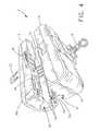
- FIG. 1is a perspective view of a power line takeoff clamp assembly in accordance with the present invention clamped about an electrical power distribution line;
- FIG. 2is a perspective view of the power line takeoff clamp assembly shown in FIG. 1 in an open state
- FIG. 3is a front view of the power line takeoff clamp assembly of FIG. 1 in the open state
- FIG. 4is another perspective view of the power line takeoff clamp assembly of FIG. 1 in the open state
- FIG. 5is a top plan view of the power line takeoff clamp assembly of FIG. 1 ;
- FIGS. 6-8are open, partially closed, and fully closed sectional views of the power line takeoff clamp assembly of FIG. 1 taken along lines A-A in FIG. 5 ;
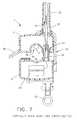
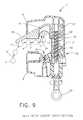
- FIGS. 9-11are open, partially closed, and fully closed sectional views of the power line takeoff clamp assembly of FIG. 1 taken along lines B-B in FIG. 5 ;
- FIG. 12is a view of the power line takeoff clamp assembly of FIG. 11 with a rib of a clamp assembly thereof moved into contact with power line 4 ;
- FIGS. 13-15are open, partially closed, and fully closed sectional views of the power line takeoff clamp assembly of FIG. 1 taken along lines C-C in FIG. 5 ;
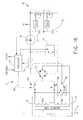
- FIG. 16is an electrical schematic of power line takeoff (PTO) electronics of the power line takeoff clamp assembly of FIG. 3 ;
- FIG. 17is a block diagram of the electronics of the power line takeoff clamp assembly shown in FIG. 3 including the PTO of FIG. 16 and a power line sensing communication module.
- a power line takeoff clamp assembly 2 in accordance with the present inventionis configured to be clamped about an electrical power distribution line 4 (shown in phantom).
- clamp assembly 2is comprised of a first, upper housing 6 and a second, lower housing 8 that can be separated as shown in FIG. 2 or drawn together as shown in FIG. 1 by way of a threaded screw 10 in a manner described hereinafter.
- Lower housing 8includes a first part 12 of a core 14 (shown best in FIG. 13 ) made from a material in which magnetic flux lines can be readily established, such as, without limitation, a transformer core.
- First part 12includes a pair of faces 16 ( a ) and 16 ( b ).
- first part 12 of core 14is generally U-shaped. However, this is not to be construed as limiting the invention since it is envisioned that first part 12 can be in the form of a half circle or any suitable and/or desirable shape that facilitates the use of core 14 in the manner described hereinafter.
- first part 12 of core 14includes therearound a plurality of windings of a wire 18 .
- the ends of the windings of wire 18are coupled to electronics 20 which comprise a power takeoff (PTO) 22 (shown schematically in FIG. 16 ) and a power line sense and communications module 24 (shown schematically in FIG. 17 ).
- PTOpower takeoff
- FIG. 17power line sense and communications module
- Power line sense and communications module 24includes a radio transceiver 26 which is coupled to an antenna 28 (shown best in FIGS. 6-8 ) which is secured at its base to lower housing 8 and which projects through a sleeve 30 , upper housing 6 and an antenna cover 32 in the manner described hereinafter with reference to FIGS. 6-8 .
- upper housing 6houses a second part 34 of core 14 (shown best in FIG. 13 ).
- Second part 34 of core 14includes faces 36 ( a ) and 36 ( b ) which can move into contact or close proximity to faces 16 ( a ) and 16 ( b ), respectively, of first part 12 when upper housing 6 and lower housing 8 are moved together as shown in FIG. 15 .
- second part 34 of core 14is desirably U-shaped. However, this is not to be construed as limiting the invention since second part 34 of core 14 can be the form of a half circle or any other suitable and/or desirable shape.
- upper housing 6includes a curved or arcuate channel 38 that is configured to receive power line 4 in the manner shown in FIG. 3 .
- Lower housing 8includes a curved or arcuate channel 40 that cooperates with channel 38 and a clamping assembly 42 , shown best in FIGS. 9-12 , for clamping power line 4 when upper housing 6 and lower housing 8 are moved together in the manner described hereinafter.
- antenna 28extends through sleeve 30 and into antenna cover 32 where the distal end of antenna 28 is disposed intermediate the connection of antenna cover 32 to upper housing 6 and the end of antenna cover 32 opposite upper housing 6 .
- antenna 28projects to its fullest extent into antenna cover 32 which acts as a barrier to the elements but permits the transmission and receipt of RF energy via antenna 28 .
- clamping assembly 42includes a so-called “duckbill” (or projection) 48 and one or more curved ribs 50 which, when upper housing 6 and lower housing 8 are in the fully closed position, press power line 4 into contact with channel 40 of lower housing 8 thereby clamping power line 4 between rib(s) 50 and channel 40 of lower housing 8 .
- the action of clamping assembly 42 to clamp power line 4 in this mannerwill now be described with reference to FIGS. 9-12 which are cross-sections taken along lines B-B in FIG. 5 .
- clamping assembly 42includes duckbill 48 which facilitates the introduction of overhead power line 4 into channel 38 (as shown by the phantom power lines 4 and arrows 4 ′ in FIG. 9 ) when mounting clamp assembly 42 to the power line 4 when upper housing 6 and lower housing 8 are in the open position shown in FIG. 9 .
- clamp assembly 42 clamping power line 4The operation of clamp assembly 42 clamping power line 4 will now be described.
- a coil spring 52surrounds the threaded portion of threaded screw 10 and extends between a shoulder 54 of a guide assembly 56 that is operative for maintaining the alignment of upper housing 6 and lower housing 8 , especially the alignment of threaded screw 10 and the female threads of clamp assembly 42 .
- the lower end of spring 52rests against shoulder 54 while the upper end of spring 52 is received in a circular slot 58 of clamp assembly 42 .
- the threaded end of screw 10is mated with the female threads disposed in clamp assembly 42 coaxial with circular slot 58 .
- Clamp assembly 42 and guide assembly 56are configured whereupon rotation of clamp assembly 42 relative to guide assembly 56 is avoided during rotation of screw 10 in the clockwise or counterclockwise direction.
- rotating screw 10 in a first directiondraws clamp assembly 42 and, hence, upper housing 6 toward lower housing 8 until upper housing 6 and lower housing 8 meet ( FIG. 11 ) and, optionally, faces 16 ( a ) and 16 ( b ) of the first part 12 of core 14 contact or come into close proximity to faces 36 ( a ) and 36 ( b ) of second part 34 of core 14 .
- FIGS. 11 and 12it can be seen that clamp assembly 42 continues to travel toward lower housing 8 after upper housing 6 and lower housing 8 are in contact. Moreover, comparing FIGS. 10 and 12 , it can be seen that the edge of rib(s) 50 that actually contact and actually clamp power line 4 in FIG. 12 reside above the surface of channel 38 prior to causing clamp assembly 42 to clamp power line 4 between the surface of channel 40 and the lower edge(s) of rib(s) 50 in the clamp position. Thus, the ends of rib(s) 50 that actually clamp power line 4 continue to move below the level of the surface of channel 38 to effect clamping of power line 4 in FIG. 12 .
- FIGS. 13-15show a cross-section of clamp assembly 2 from the fully opened to the fully closed position taken along lines C-C in FIG. 5 .
- Guide assembly 56includes a slotted stationary member 60 affixed to lower housing 8 and a slidable member 62 attached to upper housing 6 and slidable within a slot (not shown) of stationary member 60 .
- upper housing 6 and lower housing 8move together until upper housing 6 and lower housing 8 touch and, optionally, faces 16 ( a ) and 16 ( b ) of first part 12 of core 14 contact or move into close proximity to faces 36 ( a ) and 36 ( b ) of second part 34 of core 14 .
- each sealing means 64Surrounding each face 16 ( a ) and 16 ( b ) of the first part 12 of core 14 is a sealing means 64 that cooperates with a recess 66 in upper housing 6 surrounding each face 36 ( a ) and 36 ( b ) of the second part 34 of core 14 , as shown best in FIG. 4 . As shown best in FIG. 15 , when upper housing 6 and lower housing 8 are clamped together, each sealing means 64 forms with the corresponding recess 66 an environmental seal about the faces 16 and 36 of the first and second parts 12 and 34 , respectively, of core 14 .
- lower housing 6houses electronics 20 comprising a power takeoff (PTO) 22 and a power line sense and communications module 24 .
- PTO 22is designed to obtain and manage electrical power from power line 4 . Power is obtained via an inductive coupler and managed via electronic circuits and processor control described hereinafter.
- PTO 22allows apparatus, such as power line sense and communications module 24 , to be directly powered from line 4 regardless of line voltage, thereby eliminating the need for a step-down transformer.
- the inductive coupleris formed from power line 4 , core 14 and the windings of wire 18 which are wound as secondary windings Ns 1 and Ns 2 .
- core 14is formed from two individual U-shaped core pieces 12 and 34 that mechanically separate to allow core 14 to be clamped around power line 4 .
- power line 4forms a single turn primary Np in combination with core 14 .
- Secondary windings Ns 1 and Ns 2each include a number of turns that establish a suitable current ratio.
- the inductive coupleroperates as a current transformer where the current flowing in power line 4 is transformed to secondary windings Ns 1 and Ns 2 by a ratio set by the turns ratio thereof.
- PTO 22includes secondary windings Ns 1 and Ns 2 which allow the current ratio to be selected based upon power line current levels and the power needs of the apparatus that PTO 22 powers.
- PTO 22also includes a thermal reduction circuit 70 that avoids excessive power dissipation by PTO 22 . Power is stored in so-called super capacitors 72 and 74 so that backup power and/or low-duty-cycle high-current applications can be supported.
- the inductive coupleroperates as a current transformer with the windings Ns 1 and Ns 2 determining the current ratio relative to the current flowing in power line 4 .
- a switch SW 1When PTO 22 is first energized, a switch SW 1 will be closed and a switch SW 2 will be open. This is performed automatically when PTO 22 is de-energized to allow a low ratio to be selected for fast charge times of super capacitors 72 and 74 via a full-wave rectifier 76 , a current limit 78 , and a diode 80 .
- the number of windings Nsare typically limited by physical size.
- DC currentwill flow into super capacitors 72 and 74 which will charge them and produce a voltage V 1 .
- shunt regulator 82will shunt current away from super capacitors 72 and 74 halting the charge thus maintaining a constant voltage V 1 .
- Shunt regulator 82includes for each capacitor 72 and 74 sensing circuitry V sense that measures the voltage across the corresponding super capacitor and a switch, e.g., a MOSFET transistor, responsive to the output of V sense for regulating the voltage across the corresponding super capacitor.
- Shunt regulator 82prevents overcharging of super capacitors 72 and 74 , which typically have a limited voltage range.
- Voltage V 1provides electrical power to other modules comprising electronics 20 , such as, without limitation, power line sense and communications module 24 . Voltage V 1 also provides a limited amount of electrical power to a processor 84 of PTO 22 and other supporting circuitry of PTO 22 . In response to the apparatus, e.g., module 24 , drawing power from super capacitors 72 and 74 , shunt regulator 82 will regulate the voltage level of voltage V 1 by bypassing or allowing super capacitors 72 and 74 to charge. Excess power not consumed by the apparatus is thermally dissipated by shunt regulator 82 . In operation, processor 84 monitors the current flowing through current limit 78 and causes thermal reduction circuit 70 to activate when the current flowing through current limit 78 is above a predetermining level.
- Thermal reduction circuit 70includes a switch that closes to avoid current flowing through diode 80 and into capacitors 72 and 74 , and shunt regulator 82 thus significantly lowering the operating voltage of the secondary side of Ns 1 or Ns 2 thus lowering thermal dissipation.
- Diode 80blocks current from back feeding from super capacitors 72 and 74 into thermal reduction circuit 70 .
- Processor 84monitors voltage V 1 and also obtains a current reading from current limit circuit 78 . Based on these two readings, processor 84 determines when thermal reduction circuit 70 should be activated and for how long. When thermal reduction circuit 70 is operated, any apparatus power will be drawn from super capacitors 72 and 74 and the voltage will begin to drop since current is not being supplied to super capacitors 72 and 74 . Desirably, the signal to thermal reduction circuit 70 will be a pulse width modulated signal to keep voltage V 1 within predetermined bounds.
- Current limit circuit 78is designed to provide a current reading to processor 84 and to fire a clamp circuit 86 if the current exceeds a design threshold. The purpose is to prevent damage to the components of PTO 22 during high current conditions. When clamp 86 fires, the secondary current produced from the series combination of Ns 1 and Ns 2 would set the ratio to the highest range (minimum secondary current) and lowers the voltage significantly thus setting the thermal dissipation to a minimum.
- Current limit circuit 78operates on a per cycle basis so that as soon as the surge current condition is over, PTO 22 reverts back to normal operation. A benefit of operating current limit circuit 78 on a per cycle basis is that a portion of the current is allowed to continue to charge super capacitors 72 and 74 .
- Processor 84determines the ratio to select, e.g., Ns 1 or the series combination of Ns 1 and Ns 2 , based on the present level of voltage V 1 and the current flowing through diode 80 as determined via current limit 78 . If a higher ratio is desired in order to lower the secondary current, switch S 2 is closed and switch S 1 is open whereupon the secondary ratio would then be the combination of Ns 1 +Ns 2 . In no event are switches SW 1 and SW 2 closed at the same time. To ensure this, the signal on line 88 is implemented as a single binary signal controlling both switch SW 1 and SW 2 with inverse logic. The ability to switch to a higher ratio secondary winding (Ns 1 +Ns 2 ) and the use of thermal reduction circuit 70 , enhances the accuracy of current reading by current limit 78 by lowering the flux swing in core 14 .
- Super capacitors 72 and 74 , shunt regulator 82 , current limit 78 and thermal reduction circuit 70perform exactly the same whether Ns 1 alone or the series combination of Ns 1 and Ns 2 are supplying power thereto.
- processor 84will switch to the series combination of Ns 1 and Ns 2 before enabling thermal reduction circuit 70 since operation at the series combination of Ns 1 and Ns 2 will typically lower thermal dissipation significantly.
- PTO 22can provide voltage V 1 to any suitable and/or desirable apparatus, including power line sense and communications module 24 shown in block diagram in FIG. 17 .
- Module 24can include a processor 90 coupled to one or more sensors 92 for detecting conditions on power line 4 either directly or indirectly.
- sensors 92can include a current sensor, a surge current sensor, a fault current sensor, an electric field sensor, and a line temperature sensor.
- the current sensorcan be operative for providing to processor 90 an electrical value that represents the secondary current that flows in winding Ns 1 which is proportional to the current flowing in power line 4 as a function of the turns ratio of Ns 1 .
- the current sensorcan be in the form of a resistor that processor 90 converts the voltage thereacross from an analog signal to a digital signal for processing thereby.
- the surge current sensor and fault current sensorcan each be a Hall device which measures the magnetic field surrounding power line 4 .
- core 14surrounds power line 4 and concentrates the magnetic field. This increase in flux density minimizes the errors introduced as the distance between power line 4 and the Hall devices vary due to line diameter variations.
- the surge current Hall sensorproduces a voltage proportional to the flux density in core 14 . This voltage is converted to a digital signal via suitable analog-to-digital converter circuitry of processor 90 .
- Fault current sensingcan be performed by another Hall device which measures a magnetic field surrounding power line 4 .
- This Hall devicepositioned at a known distance from power line 4 is utilized for fault currents, e.g., exceeding 1000 amps.
- the fault current Hall deviceproduces a voltage proportional to the flux density surrounding power line 4 that is converted into a corresponding digital signal by analog-to-digital converter circuitry of processor 90 .
- the electric field sensormeasures the electric field emanating from the power line via parallel plates disposed on opposite sides of power line 4 .
- the voltage impressed on these parallel platescan be converted into a digital signal by analog-to-digital converter circuitry of processor 90 .
- the temperature sensormeasures the temperature of power line 4 . It does this by being in close proximity to power line 4 .
- the temperature sensorproduces a voltage proportional to the temperature which is converted into a digital signal by analog-to-digital converter circuitry of processor 90 .
- module 24includes all of the foregoing sensors. However, this is not to be construed as limiting the invention since it is envisioned that module 24 can include any one or combination of the sensors described above.
- Processor 90can communicate the results obtained from each sensor via radio transceiver 26 and antenna 28 .
- the combination of processor 90 , radio transceiver 26 , and antenna 28can also be utilized to receive data regarding sensor readings from other clamp assemblies in radio communication range and to forward said data readings to yet other clamp assemblies.
- two or more clamp assemblies 2 of the type described abovecan be utilized to form a network for communicating the status and operating characteristics of power lines 4 to which they are attached.
- the use of a plurality of clamp assemblies of the type described above in a networkis disclosed in U.S. patent application Ser. No. 12/341,300, filed on Dec. 22, 2008, which is incorporated herein by reference.
Landscapes
- Physics & Mathematics (AREA)
- General Physics & Mathematics (AREA)
- Engineering & Computer Science (AREA)
- Power Engineering (AREA)
- Condensed Matter Physics & Semiconductors (AREA)
- Emergency Protection Circuit Devices (AREA)
- Measuring Instrument Details And Bridges, And Automatic Balancing Devices (AREA)
Abstract
Description
Claims (10)
Priority Applications (4)
| Application Number | Priority Date | Filing Date | Title |
|---|---|---|---|
| US12/503,417US8536857B2 (en) | 2008-07-18 | 2009-07-15 | Power line takeoff clamp assembly |
| CA002673084ACA2673084A1 (en) | 2008-07-18 | 2009-07-17 | Power line takeoff clamp assembly |
| US13/964,201US8896291B2 (en) | 2008-07-18 | 2013-08-12 | Power line takeoff clamp assembly |
| US14/540,094US9069009B2 (en) | 2008-07-18 | 2014-11-13 | Power line takeoff clamp assembly |
Applications Claiming Priority (2)
| Application Number | Priority Date | Filing Date | Title |
|---|---|---|---|
| US8188108P | 2008-07-18 | 2008-07-18 | |
| US12/503,417US8536857B2 (en) | 2008-07-18 | 2009-07-15 | Power line takeoff clamp assembly |
Related Child Applications (1)
| Application Number | Title | Priority Date | Filing Date |
|---|---|---|---|
| US13/964,201DivisionUS8896291B2 (en) | 2008-07-18 | 2013-08-12 | Power line takeoff clamp assembly |
Publications (2)
| Publication Number | Publication Date |
|---|---|
| US20100013457A1 US20100013457A1 (en) | 2010-01-21 |
| US8536857B2true US8536857B2 (en) | 2013-09-17 |
Family
ID=41529752
Family Applications (3)
| Application Number | Title | Priority Date | Filing Date |
|---|---|---|---|
| US12/503,417Active2031-10-29US8536857B2 (en) | 2008-07-18 | 2009-07-15 | Power line takeoff clamp assembly |
| US13/964,201ActiveUS8896291B2 (en) | 2008-07-18 | 2013-08-12 | Power line takeoff clamp assembly |
| US14/540,094ActiveUS9069009B2 (en) | 2008-07-18 | 2014-11-13 | Power line takeoff clamp assembly |
Family Applications After (2)
| Application Number | Title | Priority Date | Filing Date |
|---|---|---|---|
| US13/964,201ActiveUS8896291B2 (en) | 2008-07-18 | 2013-08-12 | Power line takeoff clamp assembly |
| US14/540,094ActiveUS9069009B2 (en) | 2008-07-18 | 2014-11-13 | Power line takeoff clamp assembly |
Country Status (2)
| Country | Link |
|---|---|
| US (3) | US8536857B2 (en) |
| CA (1) | CA2673084A1 (en) |
Cited By (167)
| Publication number | Priority date | Publication date | Assignee | Title |
|---|---|---|---|---|
| US20100085036A1 (en)* | 2007-11-02 | 2010-04-08 | Cooper Technologies Company | Overhead Communicating Device |
| US20120039062A1 (en)* | 2010-08-10 | 2012-02-16 | Mcbee Bruce W | Apparatus for Mounting an Overhead Monitoring Device |
| US20140173891A1 (en)* | 2012-12-21 | 2014-06-26 | Murray W. Davis | Portable self powered line mountable electric power line and environment parameter monitoring transmitting and receiving system |
| US20140232509A1 (en)* | 2011-04-14 | 2014-08-21 | Abb Technology Ag | Electrostatic shield for a transformer |
| US8917085B2 (en)* | 2007-12-07 | 2014-12-23 | Yazaki Corporation | Current sensor |
| US20160061862A1 (en)* | 2014-08-29 | 2016-03-03 | Gregory M. Nulty | Power extraction for a medium voltage sensor using a capacitive voltage divider |
| US9379556B2 (en) | 2013-03-14 | 2016-06-28 | Cooper Technologies Company | Systems and methods for energy harvesting and current and voltage measurements |
| US9544006B2 (en) | 2014-11-20 | 2017-01-10 | At&T Intellectual Property I, L.P. | Transmission device with mode division multiplexing and methods for use therewith |
| US20170016936A1 (en)* | 2014-03-10 | 2017-01-19 | Repl International Limited | Electrical Sensor |
| US9562925B2 (en) | 2012-02-14 | 2017-02-07 | Tollgrade Communications, Inc. | Power line management system |
| US9596001B2 (en) | 2014-10-21 | 2017-03-14 | At&T Intellectual Property I, L.P. | Apparatus for providing communication services and methods thereof |
| US9608740B2 (en) | 2015-07-15 | 2017-03-28 | At&T Intellectual Property I, L.P. | Method and apparatus for launching a wave mode that mitigates interference |
| US9608692B2 (en) | 2015-06-11 | 2017-03-28 | At&T Intellectual Property I, L.P. | Repeater and methods for use therewith |
| US9615269B2 (en) | 2014-10-02 | 2017-04-04 | At&T Intellectual Property I, L.P. | Method and apparatus that provides fault tolerance in a communication network |
| US9628116B2 (en) | 2015-07-14 | 2017-04-18 | At&T Intellectual Property I, L.P. | Apparatus and methods for transmitting wireless signals |
| US9627768B2 (en) | 2014-10-21 | 2017-04-18 | At&T Intellectual Property I, L.P. | Guided-wave transmission device with non-fundamental mode propagation and methods for use therewith |
| US9640850B2 (en) | 2015-06-25 | 2017-05-02 | At&T Intellectual Property I, L.P. | Methods and apparatus for inducing a non-fundamental wave mode on a transmission medium |
| US9647454B2 (en) | 2011-08-31 | 2017-05-09 | Aclara Technologies Llc | Methods and apparatus for determining conditions of power lines |
| US9654173B2 (en) | 2014-11-20 | 2017-05-16 | At&T Intellectual Property I, L.P. | Apparatus for powering a communication device and methods thereof |
| US9653770B2 (en) | 2014-10-21 | 2017-05-16 | At&T Intellectual Property I, L.P. | Guided wave coupler, coupling module and methods for use therewith |
| US9661505B2 (en) | 2013-11-06 | 2017-05-23 | At&T Intellectual Property I, L.P. | Surface-wave communications and methods thereof |
| US9667317B2 (en) | 2015-06-15 | 2017-05-30 | At&T Intellectual Property I, L.P. | Method and apparatus for providing security using network traffic adjustments |
| US9685992B2 (en) | 2014-10-03 | 2017-06-20 | At&T Intellectual Property I, L.P. | Circuit panel network and methods thereof |
| US9692101B2 (en) | 2014-08-26 | 2017-06-27 | At&T Intellectual Property I, L.P. | Guided wave couplers for coupling electromagnetic waves between a waveguide surface and a surface of a wire |
| US9699785B2 (en) | 2012-12-05 | 2017-07-04 | At&T Intellectual Property I, L.P. | Backhaul link for distributed antenna system |
| US9705610B2 (en) | 2014-10-21 | 2017-07-11 | At&T Intellectual Property I, L.P. | Transmission device with impairment compensation and methods for use therewith |
| US9705561B2 (en) | 2015-04-24 | 2017-07-11 | At&T Intellectual Property I, L.P. | Directional coupling device and methods for use therewith |
| DE202017102941U1 (en) | 2017-05-16 | 2017-07-14 | Dipl.-Ing. H. Horstmann Gmbh | Measuring device for the inductive measurement of a voltage in an overhead line |
| US9712350B2 (en) | 2014-11-20 | 2017-07-18 | At&T Intellectual Property I, L.P. | Transmission device with channel equalization and control and methods for use therewith |
| US9722318B2 (en) | 2015-07-14 | 2017-08-01 | At&T Intellectual Property I, L.P. | Method and apparatus for coupling an antenna to a device |
| US9729197B2 (en) | 2015-10-01 | 2017-08-08 | At&T Intellectual Property I, L.P. | Method and apparatus for communicating network management traffic over a network |
| US9735833B2 (en) | 2015-07-31 | 2017-08-15 | At&T Intellectual Property I, L.P. | Method and apparatus for communications management in a neighborhood network |
| US9742462B2 (en) | 2014-12-04 | 2017-08-22 | At&T Intellectual Property I, L.P. | Transmission medium and communication interfaces and methods for use therewith |
| US9749053B2 (en) | 2015-07-23 | 2017-08-29 | At&T Intellectual Property I, L.P. | Node device, repeater and methods for use therewith |
| US9748626B2 (en) | 2015-05-14 | 2017-08-29 | At&T Intellectual Property I, L.P. | Plurality of cables having different cross-sectional shapes which are bundled together to form a transmission medium |
| US9749013B2 (en) | 2015-03-17 | 2017-08-29 | At&T Intellectual Property I, L.P. | Method and apparatus for reducing attenuation of electromagnetic waves guided by a transmission medium |
| US9762289B2 (en) | 2014-10-14 | 2017-09-12 | At&T Intellectual Property I, L.P. | Method and apparatus for transmitting or receiving signals in a transportation system |
| US9768833B2 (en) | 2014-09-15 | 2017-09-19 | At&T Intellectual Property I, L.P. | Method and apparatus for sensing a condition in a transmission medium of electromagnetic waves |
| US9769128B2 (en) | 2015-09-28 | 2017-09-19 | At&T Intellectual Property I, L.P. | Method and apparatus for encryption of communications over a network |
| US9769020B2 (en) | 2014-10-21 | 2017-09-19 | At&T Intellectual Property I, L.P. | Method and apparatus for responding to events affecting communications in a communication network |
| US9780834B2 (en) | 2014-10-21 | 2017-10-03 | At&T Intellectual Property I, L.P. | Method and apparatus for transmitting electromagnetic waves |
| US9787412B2 (en) | 2015-06-25 | 2017-10-10 | At&T Intellectual Property I, L.P. | Methods and apparatus for inducing a fundamental wave mode on a transmission medium |
| US9793954B2 (en) | 2015-04-28 | 2017-10-17 | At&T Intellectual Property I, L.P. | Magnetic coupling device and methods for use therewith |
| US9793951B2 (en) | 2015-07-15 | 2017-10-17 | At&T Intellectual Property I, L.P. | Method and apparatus for launching a wave mode that mitigates interference |
| US9794003B2 (en) | 2013-12-10 | 2017-10-17 | At&T Intellectual Property I, L.P. | Quasi-optical coupler |
| US9793955B2 (en) | 2015-04-24 | 2017-10-17 | At&T Intellectual Property I, Lp | Passive electrical coupling device and methods for use therewith |
| US9800327B2 (en) | 2014-11-20 | 2017-10-24 | At&T Intellectual Property I, L.P. | Apparatus for controlling operations of a communication device and methods thereof |
| US9820146B2 (en) | 2015-06-12 | 2017-11-14 | At&T Intellectual Property I, L.P. | Method and apparatus for authentication and identity management of communicating devices |
| US9838078B2 (en) | 2015-07-31 | 2017-12-05 | At&T Intellectual Property I, L.P. | Method and apparatus for exchanging communication signals |
| US9838896B1 (en) | 2016-12-09 | 2017-12-05 | At&T Intellectual Property I, L.P. | Method and apparatus for assessing network coverage |
| US9836957B2 (en) | 2015-07-14 | 2017-12-05 | At&T Intellectual Property I, L.P. | Method and apparatus for communicating with premises equipment |
| US9847850B2 (en) | 2014-10-14 | 2017-12-19 | At&T Intellectual Property I, L.P. | Method and apparatus for adjusting a mode of communication in a communication network |
| US9847566B2 (en) | 2015-07-14 | 2017-12-19 | At&T Intellectual Property I, L.P. | Method and apparatus for adjusting a field of a signal to mitigate interference |
| US9853342B2 (en) | 2015-07-14 | 2017-12-26 | At&T Intellectual Property I, L.P. | Dielectric transmission medium connector and methods for use therewith |
| US9860075B1 (en) | 2016-08-26 | 2018-01-02 | At&T Intellectual Property I, L.P. | Method and communication node for broadband distribution |
| US9866309B2 (en) | 2015-06-03 | 2018-01-09 | At&T Intellectual Property I, Lp | Host node device and methods for use therewith |
| US9865911B2 (en) | 2015-06-25 | 2018-01-09 | At&T Intellectual Property I, L.P. | Waveguide system for slot radiating first electromagnetic waves that are combined into a non-fundamental wave mode second electromagnetic wave on a transmission medium |
| US9866276B2 (en) | 2014-10-10 | 2018-01-09 | At&T Intellectual Property I, L.P. | Method and apparatus for arranging communication sessions in a communication system |
| US9871283B2 (en) | 2015-07-23 | 2018-01-16 | At&T Intellectual Property I, Lp | Transmission medium having a dielectric core comprised of plural members connected by a ball and socket configuration |
| US9871282B2 (en) | 2015-05-14 | 2018-01-16 | At&T Intellectual Property I, L.P. | At least one transmission medium having a dielectric surface that is covered at least in part by a second dielectric |
| US9871558B2 (en) | 2014-10-21 | 2018-01-16 | At&T Intellectual Property I, L.P. | Guided-wave transmission device and methods for use therewith |
| US9876605B1 (en) | 2016-10-21 | 2018-01-23 | At&T Intellectual Property I, L.P. | Launcher and coupling system to support desired guided wave mode |
| US9876571B2 (en) | 2015-02-20 | 2018-01-23 | At&T Intellectual Property I, Lp | Guided-wave transmission device with non-fundamental mode propagation and methods for use therewith |
| US9876264B2 (en) | 2015-10-02 | 2018-01-23 | At&T Intellectual Property I, Lp | Communication system, guided wave switch and methods for use therewith |
| US9882257B2 (en) | 2015-07-14 | 2018-01-30 | At&T Intellectual Property I, L.P. | Method and apparatus for launching a wave mode that mitigates interference |
| US9882277B2 (en) | 2015-10-02 | 2018-01-30 | At&T Intellectual Property I, Lp | Communication device and antenna assembly with actuated gimbal mount |
| US9887447B2 (en) | 2015-05-14 | 2018-02-06 | At&T Intellectual Property I, L.P. | Transmission medium having multiple cores and methods for use therewith |
| US9893795B1 (en) | 2016-12-07 | 2018-02-13 | At&T Intellectual Property I, Lp | Method and repeater for broadband distribution |
| US9906269B2 (en) | 2014-09-17 | 2018-02-27 | At&T Intellectual Property I, L.P. | Monitoring and mitigating conditions in a communication network |
| US9904535B2 (en) | 2015-09-14 | 2018-02-27 | At&T Intellectual Property I, L.P. | Method and apparatus for distributing software |
| US9912382B2 (en) | 2015-06-03 | 2018-03-06 | At&T Intellectual Property I, Lp | Network termination and methods for use therewith |
| US9912419B1 (en) | 2016-08-24 | 2018-03-06 | At&T Intellectual Property I, L.P. | Method and apparatus for managing a fault in a distributed antenna system |
| US9911020B1 (en) | 2016-12-08 | 2018-03-06 | At&T Intellectual Property I, L.P. | Method and apparatus for tracking via a radio frequency identification device |
| US9912027B2 (en) | 2015-07-23 | 2018-03-06 | At&T Intellectual Property I, L.P. | Method and apparatus for exchanging communication signals |
| US9913139B2 (en) | 2015-06-09 | 2018-03-06 | At&T Intellectual Property I, L.P. | Signal fingerprinting for authentication of communicating devices |
| US9917341B2 (en) | 2015-05-27 | 2018-03-13 | At&T Intellectual Property I, L.P. | Apparatus and method for launching electromagnetic waves and for modifying radial dimensions of the propagating electromagnetic waves |
| US9927517B1 (en) | 2016-12-06 | 2018-03-27 | At&T Intellectual Property I, L.P. | Apparatus and methods for sensing rainfall |
| US9930668B2 (en) | 2013-05-31 | 2018-03-27 | At&T Intellectual Property I, L.P. | Remote distributed antenna system |
| US9948354B2 (en) | 2015-04-28 | 2018-04-17 | At&T Intellectual Property I, L.P. | Magnetic coupling device with reflective plate and methods for use therewith |
| US9948333B2 (en) | 2015-07-23 | 2018-04-17 | At&T Intellectual Property I, L.P. | Method and apparatus for wireless communications to mitigate interference |
| US9954287B2 (en) | 2014-11-20 | 2018-04-24 | At&T Intellectual Property I, L.P. | Apparatus for converting wireless signals and electromagnetic waves and methods thereof |
| US9967173B2 (en) | 2015-07-31 | 2018-05-08 | At&T Intellectual Property I, L.P. | Method and apparatus for authentication and identity management of communicating devices |
| US9972989B2 (en) | 2014-03-31 | 2018-05-15 | Aclara Technologies Llc | Optical voltage sensing for underground medium voltage wires |
| US9973940B1 (en) | 2017-02-27 | 2018-05-15 | At&T Intellectual Property I, L.P. | Apparatus and methods for dynamic impedance matching of a guided wave launcher |
| US9991580B2 (en) | 2016-10-21 | 2018-06-05 | At&T Intellectual Property I, L.P. | Launcher and coupling system for guided wave mode cancellation |
| US9999038B2 (en) | 2013-05-31 | 2018-06-12 | At&T Intellectual Property I, L.P. | Remote distributed antenna system |
| US9998870B1 (en) | 2016-12-08 | 2018-06-12 | At&T Intellectual Property I, L.P. | Method and apparatus for proximity sensing |
| US9997819B2 (en) | 2015-06-09 | 2018-06-12 | At&T Intellectual Property I, L.P. | Transmission medium and method for facilitating propagation of electromagnetic waves via a core |
| US10009063B2 (en) | 2015-09-16 | 2018-06-26 | At&T Intellectual Property I, L.P. | Method and apparatus for use with a radio distributed antenna system having an out-of-band reference signal |
| US10009065B2 (en) | 2012-12-05 | 2018-06-26 | At&T Intellectual Property I, L.P. | Backhaul link for distributed antenna system |
| US10009067B2 (en) | 2014-12-04 | 2018-06-26 | At&T Intellectual Property I, L.P. | Method and apparatus for configuring a communication interface |
| US10009901B2 (en) | 2015-09-16 | 2018-06-26 | At&T Intellectual Property I, L.P. | Method, apparatus, and computer-readable storage medium for managing utilization of wireless resources between base stations |
| US10020844B2 (en) | 2016-12-06 | 2018-07-10 | T&T Intellectual Property I, L.P. | Method and apparatus for broadcast communication via guided waves |
| US10020587B2 (en) | 2015-07-31 | 2018-07-10 | At&T Intellectual Property I, L.P. | Radial antenna and methods for use therewith |
| US10027397B2 (en) | 2016-12-07 | 2018-07-17 | At&T Intellectual Property I, L.P. | Distributed antenna system and methods for use therewith |
| US10033107B2 (en) | 2015-07-14 | 2018-07-24 | At&T Intellectual Property I, L.P. | Method and apparatus for coupling an antenna to a device |
| US10033108B2 (en) | 2015-07-14 | 2018-07-24 | At&T Intellectual Property I, L.P. | Apparatus and methods for generating an electromagnetic wave having a wave mode that mitigates interference |
| US10044409B2 (en) | 2015-07-14 | 2018-08-07 | At&T Intellectual Property I, L.P. | Transmission medium and methods for use therewith |
| US10069535B2 (en) | 2016-12-08 | 2018-09-04 | At&T Intellectual Property I, L.P. | Apparatus and methods for launching electromagnetic waves having a certain electric field structure |
| US10079661B2 (en) | 2015-09-16 | 2018-09-18 | At&T Intellectual Property I, L.P. | Method and apparatus for use with a radio distributed antenna system having a clock reference |
| US10090594B2 (en) | 2016-11-23 | 2018-10-02 | At&T Intellectual Property I, L.P. | Antenna system having structural configurations for assembly |
| US10090606B2 (en) | 2015-07-15 | 2018-10-02 | At&T Intellectual Property I, L.P. | Antenna system with dielectric array and methods for use therewith |
| US10103801B2 (en) | 2015-06-03 | 2018-10-16 | At&T Intellectual Property I, L.P. | Host node device and methods for use therewith |
| US10103422B2 (en) | 2016-12-08 | 2018-10-16 | At&T Intellectual Property I, L.P. | Method and apparatus for mounting network devices |
| US10135147B2 (en) | 2016-10-18 | 2018-11-20 | At&T Intellectual Property I, L.P. | Apparatus and methods for launching guided waves via an antenna |
| US10136434B2 (en) | 2015-09-16 | 2018-11-20 | At&T Intellectual Property I, L.P. | Method and apparatus for use with a radio distributed antenna system having an ultra-wideband control channel |
| US10135145B2 (en) | 2016-12-06 | 2018-11-20 | At&T Intellectual Property I, L.P. | Apparatus and methods for generating an electromagnetic wave along a transmission medium |
| US10135146B2 (en) | 2016-10-18 | 2018-11-20 | At&T Intellectual Property I, L.P. | Apparatus and methods for launching guided waves via circuits |
| US10142086B2 (en) | 2015-06-11 | 2018-11-27 | At&T Intellectual Property I, L.P. | Repeater and methods for use therewith |
| US10139820B2 (en) | 2016-12-07 | 2018-11-27 | At&T Intellectual Property I, L.P. | Method and apparatus for deploying equipment of a communication system |
| US10148016B2 (en) | 2015-07-14 | 2018-12-04 | At&T Intellectual Property I, L.P. | Apparatus and methods for communicating utilizing an antenna array |
| US10144036B2 (en) | 2015-01-30 | 2018-12-04 | At&T Intellectual Property I, L.P. | Method and apparatus for mitigating interference affecting a propagation of electromagnetic waves guided by a transmission medium |
| US10170840B2 (en) | 2015-07-14 | 2019-01-01 | At&T Intellectual Property I, L.P. | Apparatus and methods for sending or receiving electromagnetic signals |
| US10168695B2 (en) | 2016-12-07 | 2019-01-01 | At&T Intellectual Property I, L.P. | Method and apparatus for controlling an unmanned aircraft |
| US10178445B2 (en) | 2016-11-23 | 2019-01-08 | At&T Intellectual Property I, L.P. | Methods, devices, and systems for load balancing between a plurality of waveguides |
| US10205655B2 (en) | 2015-07-14 | 2019-02-12 | At&T Intellectual Property I, L.P. | Apparatus and methods for communicating utilizing an antenna array and multiple communication paths |
| US10224634B2 (en) | 2016-11-03 | 2019-03-05 | At&T Intellectual Property I, L.P. | Methods and apparatus for adjusting an operational characteristic of an antenna |
| US10225025B2 (en) | 2016-11-03 | 2019-03-05 | At&T Intellectual Property I, L.P. | Method and apparatus for detecting a fault in a communication system |
| US10243784B2 (en) | 2014-11-20 | 2019-03-26 | At&T Intellectual Property I, L.P. | System for generating topology information and methods thereof |
| US10243270B2 (en) | 2016-12-07 | 2019-03-26 | At&T Intellectual Property I, L.P. | Beam adaptive multi-feed dielectric antenna system and methods for use therewith |
| US10264586B2 (en) | 2016-12-09 | 2019-04-16 | At&T Mobility Ii Llc | Cloud-based packet controller and methods for use therewith |
| US10291311B2 (en) | 2016-09-09 | 2019-05-14 | At&T Intellectual Property I, L.P. | Method and apparatus for mitigating a fault in a distributed antenna system |
| US10291334B2 (en) | 2016-11-03 | 2019-05-14 | At&T Intellectual Property I, L.P. | System for detecting a fault in a communication system |
| US10298293B2 (en) | 2017-03-13 | 2019-05-21 | At&T Intellectual Property I, L.P. | Apparatus of communication utilizing wireless network devices |
| US10305190B2 (en) | 2016-12-01 | 2019-05-28 | At&T Intellectual Property I, L.P. | Reflecting dielectric antenna system and methods for use therewith |
| US10312567B2 (en) | 2016-10-26 | 2019-06-04 | At&T Intellectual Property I, L.P. | Launcher with planar strip antenna and methods for use therewith |
| US10320586B2 (en) | 2015-07-14 | 2019-06-11 | At&T Intellectual Property I, L.P. | Apparatus and methods for generating non-interfering electromagnetic waves on an insulated transmission medium |
| US10326494B2 (en) | 2016-12-06 | 2019-06-18 | At&T Intellectual Property I, L.P. | Apparatus for measurement de-embedding and methods for use therewith |
| US10326689B2 (en) | 2016-12-08 | 2019-06-18 | At&T Intellectual Property I, L.P. | Method and system for providing alternative communication paths |
| US10340600B2 (en) | 2016-10-18 | 2019-07-02 | At&T Intellectual Property I, L.P. | Apparatus and methods for launching guided waves via plural waveguide systems |
| US10340603B2 (en) | 2016-11-23 | 2019-07-02 | At&T Intellectual Property I, L.P. | Antenna system having shielded structural configurations for assembly |
| US10341142B2 (en) | 2015-07-14 | 2019-07-02 | At&T Intellectual Property I, L.P. | Apparatus and methods for generating non-interfering electromagnetic waves on an uninsulated conductor |
| US10340601B2 (en) | 2016-11-23 | 2019-07-02 | At&T Intellectual Property I, L.P. | Multi-antenna system and methods for use therewith |
| US10340983B2 (en) | 2016-12-09 | 2019-07-02 | At&T Intellectual Property I, L.P. | Method and apparatus for surveying remote sites via guided wave communications |
| US10340573B2 (en) | 2016-10-26 | 2019-07-02 | At&T Intellectual Property I, L.P. | Launcher with cylindrical coupling device and methods for use therewith |
| US10355367B2 (en) | 2015-10-16 | 2019-07-16 | At&T Intellectual Property I, L.P. | Antenna structure for exchanging wireless signals |
| US10359749B2 (en) | 2016-12-07 | 2019-07-23 | At&T Intellectual Property I, L.P. | Method and apparatus for utilities management via guided wave communication |
| US10361489B2 (en) | 2016-12-01 | 2019-07-23 | At&T Intellectual Property I, L.P. | Dielectric dish antenna system and methods for use therewith |
| US10374316B2 (en) | 2016-10-21 | 2019-08-06 | At&T Intellectual Property I, L.P. | System and dielectric antenna with non-uniform dielectric |
| US10382976B2 (en) | 2016-12-06 | 2019-08-13 | At&T Intellectual Property I, L.P. | Method and apparatus for managing wireless communications based on communication paths and network device positions |
| US10389037B2 (en) | 2016-12-08 | 2019-08-20 | At&T Intellectual Property I, L.P. | Apparatus and methods for selecting sections of an antenna array and use therewith |
| US10389029B2 (en) | 2016-12-07 | 2019-08-20 | At&T Intellectual Property I, L.P. | Multi-feed dielectric antenna system with core selection and methods for use therewith |
| US10411356B2 (en) | 2016-12-08 | 2019-09-10 | At&T Intellectual Property I, L.P. | Apparatus and methods for selectively targeting communication devices with an antenna array |
| US10439675B2 (en) | 2016-12-06 | 2019-10-08 | At&T Intellectual Property I, L.P. | Method and apparatus for repeating guided wave communication signals |
| US10446936B2 (en) | 2016-12-07 | 2019-10-15 | At&T Intellectual Property I, L.P. | Multi-feed dielectric antenna system and methods for use therewith |
| US10498044B2 (en) | 2016-11-03 | 2019-12-03 | At&T Intellectual Property I, L.P. | Apparatus for configuring a surface of an antenna |
| US10530505B2 (en) | 2016-12-08 | 2020-01-07 | At&T Intellectual Property I, L.P. | Apparatus and methods for launching electromagnetic waves along a transmission medium |
| US10535928B2 (en) | 2016-11-23 | 2020-01-14 | At&T Intellectual Property I, L.P. | Antenna system and methods for use therewith |
| US10547348B2 (en) | 2016-12-07 | 2020-01-28 | At&T Intellectual Property I, L.P. | Method and apparatus for switching transmission mediums in a communication system |
| US10601494B2 (en) | 2016-12-08 | 2020-03-24 | At&T Intellectual Property I, L.P. | Dual-band communication device and method for use therewith |
| US10637149B2 (en) | 2016-12-06 | 2020-04-28 | At&T Intellectual Property I, L.P. | Injection molded dielectric antenna and methods for use therewith |
| US10650940B2 (en) | 2015-05-15 | 2020-05-12 | At&T Intellectual Property I, L.P. | Transmission medium having a conductive material and methods for use therewith |
| US10665942B2 (en) | 2015-10-16 | 2020-05-26 | At&T Intellectual Property I, L.P. | Method and apparatus for adjusting wireless communications |
| US10694379B2 (en) | 2016-12-06 | 2020-06-23 | At&T Intellectual Property I, L.P. | Waveguide system with device-based authentication and methods for use therewith |
| US10727599B2 (en) | 2016-12-06 | 2020-07-28 | At&T Intellectual Property I, L.P. | Launcher with slot antenna and methods for use therewith |
| US10755542B2 (en) | 2016-12-06 | 2020-08-25 | At&T Intellectual Property I, L.P. | Method and apparatus for surveillance via guided wave communication |
| US10777873B2 (en) | 2016-12-08 | 2020-09-15 | At&T Intellectual Property I, L.P. | Method and apparatus for mounting network devices |
| US10784670B2 (en) | 2015-07-23 | 2020-09-22 | At&T Intellectual Property I, L.P. | Antenna support for aligning an antenna |
| US10797781B2 (en) | 2015-06-03 | 2020-10-06 | At&T Intellectual Property I, L.P. | Client node device and methods for use therewith |
| US10811767B2 (en) | 2016-10-21 | 2020-10-20 | At&T Intellectual Property I, L.P. | System and dielectric antenna with convex dielectric radome |
| US10819035B2 (en) | 2016-12-06 | 2020-10-27 | At&T Intellectual Property I, L.P. | Launcher with helical antenna and methods for use therewith |
| US10916969B2 (en) | 2016-12-08 | 2021-02-09 | At&T Intellectual Property I, L.P. | Method and apparatus for providing power using an inductive coupling |
| US10938108B2 (en) | 2016-12-08 | 2021-03-02 | At&T Intellectual Property I, L.P. | Frequency selective multi-feed dielectric antenna system and methods for use therewith |
| US10971295B2 (en)* | 2018-12-03 | 2021-04-06 | Schweitzer Engineering Laboratories, Inc. | Two part clamping and suspension mechanism for a split toroidal current transformer |
| US11032819B2 (en) | 2016-09-15 | 2021-06-08 | At&T Intellectual Property I, L.P. | Method and apparatus for use with a radio distributed antenna system having a control channel reference signal |
| EP4030172A4 (en)* | 2019-09-13 | 2022-11-23 | Smilics Technologies S.L. | Connection, sensing and measurement device for connection to an electrical network switchgear device |
| US11662369B2 (en) | 2021-10-11 | 2023-05-30 | Schweitzer Engineering Laboratories, Inc. | Polymeric mounting suspension for a split core current transformer |
Families Citing this family (39)
| Publication number | Priority date | Publication date | Assignee | Title |
|---|---|---|---|---|
| US8002592B2 (en) | 2008-12-17 | 2011-08-23 | Hubbell Incorporated | Data collecting connection |
| US9678114B2 (en) | 2009-04-16 | 2017-06-13 | Panoramic Power Ltd. | Apparatus and methods thereof for error correction in split core current transformers |
| US9134348B2 (en) | 2009-04-16 | 2015-09-15 | Panoramic Power Ltd. | Distributed electricity metering system |
| CN102460188B (en) | 2009-04-16 | 2015-09-16 | 全景电力有限公司 | Device and method for power consumption measurement at circuit breaker point |
| JP5412251B2 (en)* | 2009-11-24 | 2014-02-12 | 株式会社サンコーシヤ | Surge current detection device |
| US9697724B2 (en) | 2010-09-22 | 2017-07-04 | Hubbell Incorporated | Transmission line measuring device and method for connectivity and monitoring |
| US10228001B2 (en) | 2010-09-22 | 2019-03-12 | Hubbell Incorporated | Transmission line measuring device and method for connectivity |
| US20120092020A1 (en)* | 2010-10-18 | 2012-04-19 | Xin Zhou | Acoustic apparatus and acoustic sensor apparatus including a clamp |
| US8890538B2 (en)* | 2011-02-09 | 2014-11-18 | General Electric Company | Sensing system and method for manufacturing the same |
| US8437157B2 (en) | 2011-03-16 | 2013-05-07 | Marmon Utility, Llc | Power line current fed power supplies producing stable load currents and related methods |
| JP5757771B2 (en)* | 2011-04-07 | 2015-07-29 | 株式会社サンコーシヤ | Surge current detection device |
| US9261414B2 (en)* | 2011-07-21 | 2016-02-16 | Electric Power Research Institute, Inc. | Overhead conductor sensor |
| NO333206B1 (en)* | 2011-11-25 | 2013-04-08 | Nortroll As | Device for monitoring power lines and device for mounting and dismantling it for power lines. |
| US9261549B2 (en)* | 2011-12-28 | 2016-02-16 | Electric Power Research Institute, Inc. | Leakage current sensor for suspension type insulator |
| US9529021B2 (en)* | 2012-07-19 | 2016-12-27 | Honeywell International Inc. | Determining current |
| JP6205127B2 (en)* | 2012-12-19 | 2017-09-27 | 富士通コンポーネント株式会社 | Current sensor |
| US10192678B2 (en)* | 2013-02-21 | 2019-01-29 | Ferrarispower Co., Ltd | Current transformer system with sensor CT and generator CT separately arranged in parallel in electric power line, and integrated system for controlling same in wireless communications network |
| JP2014211379A (en)* | 2013-04-19 | 2014-11-13 | 三菱電機株式会社 | Current measuring device, and apparatus operation detection system |
| CN104749449A (en)* | 2013-12-27 | 2015-07-01 | 贵州雅光电子科技股份有限公司 | Rapid detection method and device for rectification assembly |
| US9326399B2 (en) | 2014-03-21 | 2016-04-26 | Eaton Corporation | Electrical system and sensor attachment assembly and method therefor |
| US9933285B2 (en) | 2014-03-21 | 2018-04-03 | Eaton Intelligent Power Limited | Piezoelectric sensor assembly, and sensor attachment assembly and electrical system employing same |
| CN104051993A (en)* | 2014-06-10 | 2014-09-17 | 国家电网公司 | A cable protection clamp |
| AU2016201585A1 (en)* | 2015-04-22 | 2016-11-10 | Thomas & Betts International, Llc | Multiple coil configuration for faulted circuit indicator |
| US10024885B2 (en) | 2015-07-28 | 2018-07-17 | Panoramic Power Ltd. | Thermal management of self-powered power sensors |
| US9891252B2 (en) | 2015-07-28 | 2018-02-13 | Panoramic Power Ltd. | Thermal management of self-powered power sensors |
| AU2016305122B2 (en)* | 2015-08-10 | 2021-05-13 | National Oilwell Varco Denmark I/S | A method and a system for controlling the temperature of a fluid in an unbonded flexible pipe |
| WO2017190065A1 (en)* | 2016-04-29 | 2017-11-02 | Win Sheng Cheng | Current sensor and battery current monitoring system |
| US10267833B2 (en) | 2016-11-02 | 2019-04-23 | Equinix, Inc. | Power monitoring probe for monitoring power distribution in an electrical system |
| US10514304B2 (en) | 2017-03-23 | 2019-12-24 | Eaton Intelligent Power Limited | Temperature monitoring devices for electrical apparatus, switchgears with same and related methods |
| DE102017128234A1 (en)* | 2017-11-29 | 2019-05-29 | Phoenix Contact Gmbh & Co. Kg | Cable clip and system for monitoring a connector |
| CN108732410B (en)* | 2018-06-04 | 2024-02-20 | 清大智能(北京)科技有限公司 | Voltage measuring device for distribution line |
| DE102018118670B3 (en)* | 2018-08-01 | 2019-10-10 | Phoenix Contact Gmbh & Co. Kg | Current monitoring device |
| CN110907745B (en)* | 2018-09-14 | 2025-07-01 | 北京映翰通网络技术股份有限公司 | A distribution network fault indicator |
| US11914004B2 (en) | 2020-05-28 | 2024-02-27 | Anord Mardix (USA) Inc. | Current transformer with embedded voltage field detection and thermal sensing |
| CN111929472B (en)* | 2020-06-29 | 2023-06-30 | 国家电网有限公司 | Multifunctional high voltage test adapter box for transformer test |
| CN113451937B (en)* | 2020-10-17 | 2022-11-01 | 中国华电科工集团有限公司 | Line protection measurement and control device of intelligent substation |
| JPWO2024042788A1 (en)* | 2022-08-24 | 2024-02-29 | ||
| CN116298432B (en)* | 2023-05-24 | 2023-09-15 | 南方电网科学研究院有限责任公司 | Electric wire connecting device based on electric power standard detection |
| FR3150868B1 (en) | 2023-07-04 | 2025-10-03 | Nexans | Online monitoring system for one or more electrical cables in an electrical distribution network |
Citations (4)
| Publication number | Priority date | Publication date | Assignee | Title |
|---|---|---|---|---|
| US4728887A (en)* | 1984-06-22 | 1988-03-01 | Davis Murray W | System for rating electric power transmission lines and equipment |
| US4801937A (en)* | 1986-06-16 | 1989-01-31 | Fernandes Roosevelt A | Line mounted apparatus for remote measurement of power system or environmental parameters beyond line-of-site distanc |
| US4808917A (en)* | 1983-04-13 | 1989-02-28 | Niagara Mohawk Power Corporation | Transmission line sensor apparatus operable with near zero current line conditions |
| US5426360A (en)* | 1994-02-17 | 1995-06-20 | Niagara Mohawk Power Corporation | Secondary electrical power line parameter monitoring apparatus and system |
Family Cites Families (2)
| Publication number | Priority date | Publication date | Assignee | Title |
|---|---|---|---|---|
| US7009379B2 (en)* | 2002-09-12 | 2006-03-07 | Landis & Gyr, Inc. | Electricity meter with power supply load management |
| US8076925B2 (en)* | 2009-10-28 | 2011-12-13 | Optisense Network, Inc. | Optical sensor assembly for installation on a current carrying cable |
- 2009
- 2009-07-15USUS12/503,417patent/US8536857B2/enactiveActive
- 2009-07-17CACA002673084Apatent/CA2673084A1/ennot_activeAbandoned
- 2013
- 2013-08-12USUS13/964,201patent/US8896291B2/enactiveActive
- 2014
- 2014-11-13USUS14/540,094patent/US9069009B2/enactiveActive
Patent Citations (4)
| Publication number | Priority date | Publication date | Assignee | Title |
|---|---|---|---|---|
| US4808917A (en)* | 1983-04-13 | 1989-02-28 | Niagara Mohawk Power Corporation | Transmission line sensor apparatus operable with near zero current line conditions |
| US4728887A (en)* | 1984-06-22 | 1988-03-01 | Davis Murray W | System for rating electric power transmission lines and equipment |
| US4801937A (en)* | 1986-06-16 | 1989-01-31 | Fernandes Roosevelt A | Line mounted apparatus for remote measurement of power system or environmental parameters beyond line-of-site distanc |
| US5426360A (en)* | 1994-02-17 | 1995-06-20 | Niagara Mohawk Power Corporation | Secondary electrical power line parameter monitoring apparatus and system |
Cited By (229)
| Publication number | Priority date | Publication date | Assignee | Title |
|---|---|---|---|---|
| US9383394B2 (en) | 2007-11-02 | 2016-07-05 | Cooper Technologies Company | Overhead communicating device |
| US20100085036A1 (en)* | 2007-11-02 | 2010-04-08 | Cooper Technologies Company | Overhead Communicating Device |
| US8917085B2 (en)* | 2007-12-07 | 2014-12-23 | Yazaki Corporation | Current sensor |
| US9000875B2 (en) | 2010-08-10 | 2015-04-07 | Cooper Technologies Company | Apparatus and method for mounting an overhead device |
| US9368275B2 (en) | 2010-08-10 | 2016-06-14 | Cooper Technologies Company | Adjustable overhead conductor monitoring device |
| US8760254B2 (en) | 2010-08-10 | 2014-06-24 | Cooper Technologies Company | Apparatus and method for mounting an overhead monitoring device |
| US8760151B2 (en)* | 2010-08-10 | 2014-06-24 | Cooper Technologies Company | Ajustable overhead conductor monitoring device |
| US20120039062A1 (en)* | 2010-08-10 | 2012-02-16 | Mcbee Bruce W | Apparatus for Mounting an Overhead Monitoring Device |
| US20140232509A1 (en)* | 2011-04-14 | 2014-08-21 | Abb Technology Ag | Electrostatic shield for a transformer |
| US9472337B2 (en)* | 2011-04-14 | 2016-10-18 | Abb Schweiz Ag | Electrostatic shield for a transformer |
| US9647454B2 (en) | 2011-08-31 | 2017-05-09 | Aclara Technologies Llc | Methods and apparatus for determining conditions of power lines |
| US12249829B2 (en) | 2011-08-31 | 2025-03-11 | Aclara Technologies Llc | Methods and apparatus for determining conditions of power lines |
| US9562925B2 (en) | 2012-02-14 | 2017-02-07 | Tollgrade Communications, Inc. | Power line management system |
| US10041968B2 (en) | 2012-02-14 | 2018-08-07 | Aclara Technologies Llc | Power line management system |
| US10009065B2 (en) | 2012-12-05 | 2018-06-26 | At&T Intellectual Property I, L.P. | Backhaul link for distributed antenna system |
| US9699785B2 (en) | 2012-12-05 | 2017-07-04 | At&T Intellectual Property I, L.P. | Backhaul link for distributed antenna system |
| US10194437B2 (en) | 2012-12-05 | 2019-01-29 | At&T Intellectual Property I, L.P. | Backhaul link for distributed antenna system |
| US9788326B2 (en) | 2012-12-05 | 2017-10-10 | At&T Intellectual Property I, L.P. | Backhaul link for distributed antenna system |
| US9140764B2 (en) | 2012-12-21 | 2015-09-22 | Murray W. Davis | Portable self powered line mounted device and method for measuring the voltage of electric power line conductors |
| US9380857B2 (en) | 2012-12-21 | 2016-07-05 | Murray W. Davis | Portable self powered line mountable device for measuring and transmitting ambient temperature |
| US9198500B2 (en)* | 2012-12-21 | 2015-12-01 | Murray W. Davis | Portable self powered line mountable electric power line and environment parameter monitoring transmitting and receiving system |
| US9241559B2 (en) | 2012-12-21 | 2016-01-26 | Murray W. Davis | Portable self powered line mountable device for measuring and transmitting relative humidity |
| US9271563B2 (en) | 2012-12-21 | 2016-03-01 | Murray W. Davis | Portable self powered line mountable electric power line current monitoring transmitting and receiving system |
| US9143745B2 (en) | 2012-12-21 | 2015-09-22 | Murray W. Davis | Portable self powered line mounted high speed camera system for overhead electric power lines |
| US9078512B2 (en) | 2012-12-21 | 2015-07-14 | Murray W. Davis | Portable self powered line mounted conductor ice thickness measuring system for overhead electric power lines |
| US20140173891A1 (en)* | 2012-12-21 | 2014-06-26 | Murray W. Davis | Portable self powered line mountable electric power line and environment parameter monitoring transmitting and receiving system |
| US9066578B2 (en) | 2012-12-21 | 2015-06-30 | Murray W. Davis | Fixed tap low threshold current power supply |
| US9167885B2 (en) | 2012-12-21 | 2015-10-27 | Murray W. Davis | Automatic switchable low threshold current power supply |
| US9060594B2 (en) | 2012-12-21 | 2015-06-23 | Murray W. Davis | Automatic switchable low threshold current power supply |
| US9055808B2 (en) | 2012-12-21 | 2015-06-16 | Murray W. Davis | Portable self powered line mountable device for measuring and transmitting the undisturbed conductor temperature of electric power line conductors |
| US8952679B2 (en) | 2012-12-21 | 2015-02-10 | Murray W. Davis | Portable self powered line mountable electric power line current monitoring transmitting and receiving system |
| US8943926B2 (en) | 2012-12-21 | 2015-02-03 | Murray W. Davis | Hotstick assembly for installing and removing devices from high voltage energized overhead power lines |
| US8933687B2 (en) | 2012-12-21 | 2015-01-13 | Murray W. Davis | Portable self powered line mountable device for measuring and transmitting solar radiation |
| US8913126B2 (en) | 2012-12-21 | 2014-12-16 | Murray W. Davis | Portable self powered line mounted high speed camera system for overhead electric power lines |
| US8912920B2 (en) | 2012-12-21 | 2014-12-16 | Murray W. Davis | Switchable low threshold current power supply |
| US9379556B2 (en) | 2013-03-14 | 2016-06-28 | Cooper Technologies Company | Systems and methods for energy harvesting and current and voltage measurements |
| US9930668B2 (en) | 2013-05-31 | 2018-03-27 | At&T Intellectual Property I, L.P. | Remote distributed antenna system |
| US10051630B2 (en) | 2013-05-31 | 2018-08-14 | At&T Intellectual Property I, L.P. | Remote distributed antenna system |
| US10091787B2 (en) | 2013-05-31 | 2018-10-02 | At&T Intellectual Property I, L.P. | Remote distributed antenna system |
| US9999038B2 (en) | 2013-05-31 | 2018-06-12 | At&T Intellectual Property I, L.P. | Remote distributed antenna system |
| US9661505B2 (en) | 2013-11-06 | 2017-05-23 | At&T Intellectual Property I, L.P. | Surface-wave communications and methods thereof |
| US9674711B2 (en) | 2013-11-06 | 2017-06-06 | At&T Intellectual Property I, L.P. | Surface-wave communications and methods thereof |
| US9794003B2 (en) | 2013-12-10 | 2017-10-17 | At&T Intellectual Property I, L.P. | Quasi-optical coupler |
| US9876584B2 (en) | 2013-12-10 | 2018-01-23 | At&T Intellectual Property I, L.P. | Quasi-optical coupler |
| US10514396B2 (en)* | 2014-03-10 | 2019-12-24 | Repl International Limited | Electrical sensor attachable to an electrical distribution cable |
| US20170016936A1 (en)* | 2014-03-10 | 2017-01-19 | Repl International Limited | Electrical Sensor |
| US9972989B2 (en) | 2014-03-31 | 2018-05-15 | Aclara Technologies Llc | Optical voltage sensing for underground medium voltage wires |
| US10096881B2 (en) | 2014-08-26 | 2018-10-09 | At&T Intellectual Property I, L.P. | Guided wave couplers for coupling electromagnetic waves to an outer surface of a transmission medium |
| US9692101B2 (en) | 2014-08-26 | 2017-06-27 | At&T Intellectual Property I, L.P. | Guided wave couplers for coupling electromagnetic waves between a waveguide surface and a surface of a wire |
| US20160061862A1 (en)* | 2014-08-29 | 2016-03-03 | Gregory M. Nulty | Power extraction for a medium voltage sensor using a capacitive voltage divider |
| US10203355B2 (en)* | 2014-08-29 | 2019-02-12 | Aclara Technologies Llc | Power extraction for a medium voltage sensor using a capacitive voltage divider |
| US9768833B2 (en) | 2014-09-15 | 2017-09-19 | At&T Intellectual Property I, L.P. | Method and apparatus for sensing a condition in a transmission medium of electromagnetic waves |
| US10063280B2 (en) | 2014-09-17 | 2018-08-28 | At&T Intellectual Property I, L.P. | Monitoring and mitigating conditions in a communication network |
| US9906269B2 (en) | 2014-09-17 | 2018-02-27 | At&T Intellectual Property I, L.P. | Monitoring and mitigating conditions in a communication network |
| US9998932B2 (en) | 2014-10-02 | 2018-06-12 | At&T Intellectual Property I, L.P. | Method and apparatus that provides fault tolerance in a communication network |
| US9973416B2 (en) | 2014-10-02 | 2018-05-15 | At&T Intellectual Property I, L.P. | Method and apparatus that provides fault tolerance in a communication network |
| US9615269B2 (en) | 2014-10-02 | 2017-04-04 | At&T Intellectual Property I, L.P. | Method and apparatus that provides fault tolerance in a communication network |
| US9685992B2 (en) | 2014-10-03 | 2017-06-20 | At&T Intellectual Property I, L.P. | Circuit panel network and methods thereof |
| US9866276B2 (en) | 2014-10-10 | 2018-01-09 | At&T Intellectual Property I, L.P. | Method and apparatus for arranging communication sessions in a communication system |
| US9973299B2 (en) | 2014-10-14 | 2018-05-15 | At&T Intellectual Property I, L.P. | Method and apparatus for adjusting a mode of communication in a communication network |
| US9847850B2 (en) | 2014-10-14 | 2017-12-19 | At&T Intellectual Property I, L.P. | Method and apparatus for adjusting a mode of communication in a communication network |
| US9762289B2 (en) | 2014-10-14 | 2017-09-12 | At&T Intellectual Property I, L.P. | Method and apparatus for transmitting or receiving signals in a transportation system |
| US9705610B2 (en) | 2014-10-21 | 2017-07-11 | At&T Intellectual Property I, L.P. | Transmission device with impairment compensation and methods for use therewith |
| US9653770B2 (en) | 2014-10-21 | 2017-05-16 | At&T Intellectual Property I, L.P. | Guided wave coupler, coupling module and methods for use therewith |
| US9769020B2 (en) | 2014-10-21 | 2017-09-19 | At&T Intellectual Property I, L.P. | Method and apparatus for responding to events affecting communications in a communication network |
| US9780834B2 (en) | 2014-10-21 | 2017-10-03 | At&T Intellectual Property I, L.P. | Method and apparatus for transmitting electromagnetic waves |
| US9912033B2 (en) | 2014-10-21 | 2018-03-06 | At&T Intellectual Property I, Lp | Guided wave coupler, coupling module and methods for use therewith |
| US9596001B2 (en) | 2014-10-21 | 2017-03-14 | At&T Intellectual Property I, L.P. | Apparatus for providing communication services and methods thereof |
| US9876587B2 (en) | 2014-10-21 | 2018-01-23 | At&T Intellectual Property I, L.P. | Transmission device with impairment compensation and methods for use therewith |
| US9871558B2 (en) | 2014-10-21 | 2018-01-16 | At&T Intellectual Property I, L.P. | Guided-wave transmission device and methods for use therewith |
| US9948355B2 (en) | 2014-10-21 | 2018-04-17 | At&T Intellectual Property I, L.P. | Apparatus for providing communication services and methods thereof |
| US9627768B2 (en) | 2014-10-21 | 2017-04-18 | At&T Intellectual Property I, L.P. | Guided-wave transmission device with non-fundamental mode propagation and methods for use therewith |
| US9954286B2 (en) | 2014-10-21 | 2018-04-24 | At&T Intellectual Property I, L.P. | Guided-wave transmission device with non-fundamental mode propagation and methods for use therewith |
| US9960808B2 (en) | 2014-10-21 | 2018-05-01 | At&T Intellectual Property I, L.P. | Guided-wave transmission device and methods for use therewith |
| US9800327B2 (en) | 2014-11-20 | 2017-10-24 | At&T Intellectual Property I, L.P. | Apparatus for controlling operations of a communication device and methods thereof |
| US9954287B2 (en) | 2014-11-20 | 2018-04-24 | At&T Intellectual Property I, L.P. | Apparatus for converting wireless signals and electromagnetic waves and methods thereof |
| US9712350B2 (en) | 2014-11-20 | 2017-07-18 | At&T Intellectual Property I, L.P. | Transmission device with channel equalization and control and methods for use therewith |
| US9742521B2 (en) | 2014-11-20 | 2017-08-22 | At&T Intellectual Property I, L.P. | Transmission device with mode division multiplexing and methods for use therewith |
| US9544006B2 (en) | 2014-11-20 | 2017-01-10 | At&T Intellectual Property I, L.P. | Transmission device with mode division multiplexing and methods for use therewith |
| US9654173B2 (en) | 2014-11-20 | 2017-05-16 | At&T Intellectual Property I, L.P. | Apparatus for powering a communication device and methods thereof |
| US10243784B2 (en) | 2014-11-20 | 2019-03-26 | At&T Intellectual Property I, L.P. | System for generating topology information and methods thereof |
| US9749083B2 (en) | 2014-11-20 | 2017-08-29 | At&T Intellectual Property I, L.P. | Transmission device with mode division multiplexing and methods for use therewith |
| US9742462B2 (en) | 2014-12-04 | 2017-08-22 | At&T Intellectual Property I, L.P. | Transmission medium and communication interfaces and methods for use therewith |
| US10009067B2 (en) | 2014-12-04 | 2018-06-26 | At&T Intellectual Property I, L.P. | Method and apparatus for configuring a communication interface |
| US10144036B2 (en) | 2015-01-30 | 2018-12-04 | At&T Intellectual Property I, L.P. | Method and apparatus for mitigating interference affecting a propagation of electromagnetic waves guided by a transmission medium |
| US9876571B2 (en) | 2015-02-20 | 2018-01-23 | At&T Intellectual Property I, Lp | Guided-wave transmission device with non-fundamental mode propagation and methods for use therewith |
| US9876570B2 (en) | 2015-02-20 | 2018-01-23 | At&T Intellectual Property I, Lp | Guided-wave transmission device with non-fundamental mode propagation and methods for use therewith |
| US9749013B2 (en) | 2015-03-17 | 2017-08-29 | At&T Intellectual Property I, L.P. | Method and apparatus for reducing attenuation of electromagnetic waves guided by a transmission medium |
| US9793955B2 (en) | 2015-04-24 | 2017-10-17 | At&T Intellectual Property I, Lp | Passive electrical coupling device and methods for use therewith |
| US10224981B2 (en) | 2015-04-24 | 2019-03-05 | At&T Intellectual Property I, Lp | Passive electrical coupling device and methods for use therewith |
| US9831912B2 (en) | 2015-04-24 | 2017-11-28 | At&T Intellectual Property I, Lp | Directional coupling device and methods for use therewith |
| US9705561B2 (en) | 2015-04-24 | 2017-07-11 | At&T Intellectual Property I, L.P. | Directional coupling device and methods for use therewith |
| US9948354B2 (en) | 2015-04-28 | 2018-04-17 | At&T Intellectual Property I, L.P. | Magnetic coupling device with reflective plate and methods for use therewith |
| US9793954B2 (en) | 2015-04-28 | 2017-10-17 | At&T Intellectual Property I, L.P. | Magnetic coupling device and methods for use therewith |
| US9871282B2 (en) | 2015-05-14 | 2018-01-16 | At&T Intellectual Property I, L.P. | At least one transmission medium having a dielectric surface that is covered at least in part by a second dielectric |
| US9748626B2 (en) | 2015-05-14 | 2017-08-29 | At&T Intellectual Property I, L.P. | Plurality of cables having different cross-sectional shapes which are bundled together to form a transmission medium |
| US9887447B2 (en) | 2015-05-14 | 2018-02-06 | At&T Intellectual Property I, L.P. | Transmission medium having multiple cores and methods for use therewith |
| US10650940B2 (en) | 2015-05-15 | 2020-05-12 | At&T Intellectual Property I, L.P. | Transmission medium having a conductive material and methods for use therewith |
| US9917341B2 (en) | 2015-05-27 | 2018-03-13 | At&T Intellectual Property I, L.P. | Apparatus and method for launching electromagnetic waves and for modifying radial dimensions of the propagating electromagnetic waves |
| US9935703B2 (en) | 2015-06-03 | 2018-04-03 | At&T Intellectual Property I, L.P. | Host node device and methods for use therewith |
| US10797781B2 (en) | 2015-06-03 | 2020-10-06 | At&T Intellectual Property I, L.P. | Client node device and methods for use therewith |
| US9866309B2 (en) | 2015-06-03 | 2018-01-09 | At&T Intellectual Property I, Lp | Host node device and methods for use therewith |
| US9912382B2 (en) | 2015-06-03 | 2018-03-06 | At&T Intellectual Property I, Lp | Network termination and methods for use therewith |
| US10103801B2 (en) | 2015-06-03 | 2018-10-16 | At&T Intellectual Property I, L.P. | Host node device and methods for use therewith |
| US10812174B2 (en) | 2015-06-03 | 2020-10-20 | At&T Intellectual Property I, L.P. | Client node device and methods for use therewith |
| US9967002B2 (en) | 2015-06-03 | 2018-05-08 | At&T Intellectual I, Lp | Network termination and methods for use therewith |
| US9912381B2 (en) | 2015-06-03 | 2018-03-06 | At&T Intellectual Property I, Lp | Network termination and methods for use therewith |
| US10050697B2 (en) | 2015-06-03 | 2018-08-14 | At&T Intellectual Property I, L.P. | Host node device and methods for use therewith |
| US9997819B2 (en) | 2015-06-09 | 2018-06-12 | At&T Intellectual Property I, L.P. | Transmission medium and method for facilitating propagation of electromagnetic waves via a core |
| US9913139B2 (en) | 2015-06-09 | 2018-03-06 | At&T Intellectual Property I, L.P. | Signal fingerprinting for authentication of communicating devices |
| US10027398B2 (en) | 2015-06-11 | 2018-07-17 | At&T Intellectual Property I, Lp | Repeater and methods for use therewith |
| US9608692B2 (en) | 2015-06-11 | 2017-03-28 | At&T Intellectual Property I, L.P. | Repeater and methods for use therewith |
| US10142086B2 (en) | 2015-06-11 | 2018-11-27 | At&T Intellectual Property I, L.P. | Repeater and methods for use therewith |
| US10142010B2 (en) | 2015-06-11 | 2018-11-27 | At&T Intellectual Property I, L.P. | Repeater and methods for use therewith |
| US9820146B2 (en) | 2015-06-12 | 2017-11-14 | At&T Intellectual Property I, L.P. | Method and apparatus for authentication and identity management of communicating devices |
| US9667317B2 (en) | 2015-06-15 | 2017-05-30 | At&T Intellectual Property I, L.P. | Method and apparatus for providing security using network traffic adjustments |
| US10069185B2 (en) | 2015-06-25 | 2018-09-04 | At&T Intellectual Property I, L.P. | Methods and apparatus for inducing a non-fundamental wave mode on a transmission medium |
| US9787412B2 (en) | 2015-06-25 | 2017-10-10 | At&T Intellectual Property I, L.P. | Methods and apparatus for inducing a fundamental wave mode on a transmission medium |
| US9882657B2 (en) | 2015-06-25 | 2018-01-30 | At&T Intellectual Property I, L.P. | Methods and apparatus for inducing a fundamental wave mode on a transmission medium |
| US9640850B2 (en) | 2015-06-25 | 2017-05-02 | At&T Intellectual Property I, L.P. | Methods and apparatus for inducing a non-fundamental wave mode on a transmission medium |
| US9865911B2 (en) | 2015-06-25 | 2018-01-09 | At&T Intellectual Property I, L.P. | Waveguide system for slot radiating first electromagnetic waves that are combined into a non-fundamental wave mode second electromagnetic wave on a transmission medium |
| US10320586B2 (en) | 2015-07-14 | 2019-06-11 | At&T Intellectual Property I, L.P. | Apparatus and methods for generating non-interfering electromagnetic waves on an insulated transmission medium |
| US9882257B2 (en) | 2015-07-14 | 2018-01-30 | At&T Intellectual Property I, L.P. | Method and apparatus for launching a wave mode that mitigates interference |
| US9853342B2 (en) | 2015-07-14 | 2017-12-26 | At&T Intellectual Property I, L.P. | Dielectric transmission medium connector and methods for use therewith |
| US9847566B2 (en) | 2015-07-14 | 2017-12-19 | At&T Intellectual Property I, L.P. | Method and apparatus for adjusting a field of a signal to mitigate interference |
| US10341142B2 (en) | 2015-07-14 | 2019-07-02 | At&T Intellectual Property I, L.P. | Apparatus and methods for generating non-interfering electromagnetic waves on an uninsulated conductor |
| US9836957B2 (en) | 2015-07-14 | 2017-12-05 | At&T Intellectual Property I, L.P. | Method and apparatus for communicating with premises equipment |
| US10148016B2 (en) | 2015-07-14 | 2018-12-04 | At&T Intellectual Property I, L.P. | Apparatus and methods for communicating utilizing an antenna array |
| US9947982B2 (en) | 2015-07-14 | 2018-04-17 | At&T Intellectual Property I, Lp | Dielectric transmission medium connector and methods for use therewith |
| US9929755B2 (en) | 2015-07-14 | 2018-03-27 | At&T Intellectual Property I, L.P. | Method and apparatus for coupling an antenna to a device |
| US10205655B2 (en) | 2015-07-14 | 2019-02-12 | At&T Intellectual Property I, L.P. | Apparatus and methods for communicating utilizing an antenna array and multiple communication paths |
| US10170840B2 (en) | 2015-07-14 | 2019-01-01 | At&T Intellectual Property I, L.P. | Apparatus and methods for sending or receiving electromagnetic signals |
| US9722318B2 (en) | 2015-07-14 | 2017-08-01 | At&T Intellectual Property I, L.P. | Method and apparatus for coupling an antenna to a device |
| US9628116B2 (en) | 2015-07-14 | 2017-04-18 | At&T Intellectual Property I, L.P. | Apparatus and methods for transmitting wireless signals |
| US10033107B2 (en) | 2015-07-14 | 2018-07-24 | At&T Intellectual Property I, L.P. | Method and apparatus for coupling an antenna to a device |
| US10044409B2 (en) | 2015-07-14 | 2018-08-07 | At&T Intellectual Property I, L.P. | Transmission medium and methods for use therewith |
| US10033108B2 (en) | 2015-07-14 | 2018-07-24 | At&T Intellectual Property I, L.P. | Apparatus and methods for generating an electromagnetic wave having a wave mode that mitigates interference |
| US9793951B2 (en) | 2015-07-15 | 2017-10-17 | At&T Intellectual Property I, L.P. | Method and apparatus for launching a wave mode that mitigates interference |
| US10090606B2 (en) | 2015-07-15 | 2018-10-02 | At&T Intellectual Property I, L.P. | Antenna system with dielectric array and methods for use therewith |
| US9608740B2 (en) | 2015-07-15 | 2017-03-28 | At&T Intellectual Property I, L.P. | Method and apparatus for launching a wave mode that mitigates interference |
| US9948333B2 (en) | 2015-07-23 | 2018-04-17 | At&T Intellectual Property I, L.P. | Method and apparatus for wireless communications to mitigate interference |
| US10074886B2 (en) | 2015-07-23 | 2018-09-11 | At&T Intellectual Property I, L.P. | Dielectric transmission medium comprising a plurality of rigid dielectric members coupled together in a ball and socket configuration |
| US9749053B2 (en) | 2015-07-23 | 2017-08-29 | At&T Intellectual Property I, L.P. | Node device, repeater and methods for use therewith |
| US9871283B2 (en) | 2015-07-23 | 2018-01-16 | At&T Intellectual Property I, Lp | Transmission medium having a dielectric core comprised of plural members connected by a ball and socket configuration |
| US9806818B2 (en) | 2015-07-23 | 2017-10-31 | At&T Intellectual Property I, Lp | Node device, repeater and methods for use therewith |
| US10784670B2 (en) | 2015-07-23 | 2020-09-22 | At&T Intellectual Property I, L.P. | Antenna support for aligning an antenna |
| US9912027B2 (en) | 2015-07-23 | 2018-03-06 | At&T Intellectual Property I, L.P. | Method and apparatus for exchanging communication signals |
| US10020587B2 (en) | 2015-07-31 | 2018-07-10 | At&T Intellectual Property I, L.P. | Radial antenna and methods for use therewith |
| US9967173B2 (en) | 2015-07-31 | 2018-05-08 | At&T Intellectual Property I, L.P. | Method and apparatus for authentication and identity management of communicating devices |
| US9735833B2 (en) | 2015-07-31 | 2017-08-15 | At&T Intellectual Property I, L.P. | Method and apparatus for communications management in a neighborhood network |
| US9838078B2 (en) | 2015-07-31 | 2017-12-05 | At&T Intellectual Property I, L.P. | Method and apparatus for exchanging communication signals |
| US9904535B2 (en) | 2015-09-14 | 2018-02-27 | At&T Intellectual Property I, L.P. | Method and apparatus for distributing software |
| US10009063B2 (en) | 2015-09-16 | 2018-06-26 | At&T Intellectual Property I, L.P. | Method and apparatus for use with a radio distributed antenna system having an out-of-band reference signal |
| US10079661B2 (en) | 2015-09-16 | 2018-09-18 | At&T Intellectual Property I, L.P. | Method and apparatus for use with a radio distributed antenna system having a clock reference |
| US10009901B2 (en) | 2015-09-16 | 2018-06-26 | At&T Intellectual Property I, L.P. | Method, apparatus, and computer-readable storage medium for managing utilization of wireless resources between base stations |
| US10225842B2 (en) | 2015-09-16 | 2019-03-05 | At&T Intellectual Property I, L.P. | Method, device and storage medium for communications using a modulated signal and a reference signal |
| US10349418B2 (en) | 2015-09-16 | 2019-07-09 | At&T Intellectual Property I, L.P. | Method and apparatus for managing utilization of wireless resources via use of a reference signal to reduce distortion |
| US10136434B2 (en) | 2015-09-16 | 2018-11-20 | At&T Intellectual Property I, L.P. | Method and apparatus for use with a radio distributed antenna system having an ultra-wideband control channel |
| US9769128B2 (en) | 2015-09-28 | 2017-09-19 | At&T Intellectual Property I, L.P. | Method and apparatus for encryption of communications over a network |
| US9729197B2 (en) | 2015-10-01 | 2017-08-08 | At&T Intellectual Property I, L.P. | Method and apparatus for communicating network management traffic over a network |
| US9882277B2 (en) | 2015-10-02 | 2018-01-30 | At&T Intellectual Property I, Lp | Communication device and antenna assembly with actuated gimbal mount |
| US9876264B2 (en) | 2015-10-02 | 2018-01-23 | At&T Intellectual Property I, Lp | Communication system, guided wave switch and methods for use therewith |
| US10355367B2 (en) | 2015-10-16 | 2019-07-16 | At&T Intellectual Property I, L.P. | Antenna structure for exchanging wireless signals |
| US10665942B2 (en) | 2015-10-16 | 2020-05-26 | At&T Intellectual Property I, L.P. | Method and apparatus for adjusting wireless communications |
| US9912419B1 (en) | 2016-08-24 | 2018-03-06 | At&T Intellectual Property I, L.P. | Method and apparatus for managing a fault in a distributed antenna system |
| US9860075B1 (en) | 2016-08-26 | 2018-01-02 | At&T Intellectual Property I, L.P. | Method and communication node for broadband distribution |
| US10291311B2 (en) | 2016-09-09 | 2019-05-14 | At&T Intellectual Property I, L.P. | Method and apparatus for mitigating a fault in a distributed antenna system |
| US11032819B2 (en) | 2016-09-15 | 2021-06-08 | At&T Intellectual Property I, L.P. | Method and apparatus for use with a radio distributed antenna system having a control channel reference signal |
| US10135147B2 (en) | 2016-10-18 | 2018-11-20 | At&T Intellectual Property I, L.P. | Apparatus and methods for launching guided waves via an antenna |
| US10340600B2 (en) | 2016-10-18 | 2019-07-02 | At&T Intellectual Property I, L.P. | Apparatus and methods for launching guided waves via plural waveguide systems |
| US10135146B2 (en) | 2016-10-18 | 2018-11-20 | At&T Intellectual Property I, L.P. | Apparatus and methods for launching guided waves via circuits |
| US9876605B1 (en) | 2016-10-21 | 2018-01-23 | At&T Intellectual Property I, L.P. | Launcher and coupling system to support desired guided wave mode |
| US9991580B2 (en) | 2016-10-21 | 2018-06-05 | At&T Intellectual Property I, L.P. | Launcher and coupling system for guided wave mode cancellation |
| US10811767B2 (en) | 2016-10-21 | 2020-10-20 | At&T Intellectual Property I, L.P. | System and dielectric antenna with convex dielectric radome |
| US10374316B2 (en) | 2016-10-21 | 2019-08-06 | At&T Intellectual Property I, L.P. | System and dielectric antenna with non-uniform dielectric |
| US10340573B2 (en) | 2016-10-26 | 2019-07-02 | At&T Intellectual Property I, L.P. | Launcher with cylindrical coupling device and methods for use therewith |
| US10312567B2 (en) | 2016-10-26 | 2019-06-04 | At&T Intellectual Property I, L.P. | Launcher with planar strip antenna and methods for use therewith |
| US10225025B2 (en) | 2016-11-03 | 2019-03-05 | At&T Intellectual Property I, L.P. | Method and apparatus for detecting a fault in a communication system |
| US10224634B2 (en) | 2016-11-03 | 2019-03-05 | At&T Intellectual Property I, L.P. | Methods and apparatus for adjusting an operational characteristic of an antenna |
| US10498044B2 (en) | 2016-11-03 | 2019-12-03 | At&T Intellectual Property I, L.P. | Apparatus for configuring a surface of an antenna |
| US10291334B2 (en) | 2016-11-03 | 2019-05-14 | At&T Intellectual Property I, L.P. | System for detecting a fault in a communication system |
| US10090594B2 (en) | 2016-11-23 | 2018-10-02 | At&T Intellectual Property I, L.P. | Antenna system having structural configurations for assembly |
| US10535928B2 (en) | 2016-11-23 | 2020-01-14 | At&T Intellectual Property I, L.P. | Antenna system and methods for use therewith |
| US10340601B2 (en) | 2016-11-23 | 2019-07-02 | At&T Intellectual Property I, L.P. | Multi-antenna system and methods for use therewith |
| US10178445B2 (en) | 2016-11-23 | 2019-01-08 | At&T Intellectual Property I, L.P. | Methods, devices, and systems for load balancing between a plurality of waveguides |
| US10340603B2 (en) | 2016-11-23 | 2019-07-02 | At&T Intellectual Property I, L.P. | Antenna system having shielded structural configurations for assembly |
| US10305190B2 (en) | 2016-12-01 | 2019-05-28 | At&T Intellectual Property I, L.P. | Reflecting dielectric antenna system and methods for use therewith |
| US10361489B2 (en) | 2016-12-01 | 2019-07-23 | At&T Intellectual Property I, L.P. | Dielectric dish antenna system and methods for use therewith |
| US10439675B2 (en) | 2016-12-06 | 2019-10-08 | At&T Intellectual Property I, L.P. | Method and apparatus for repeating guided wave communication signals |
| US10326494B2 (en) | 2016-12-06 | 2019-06-18 | At&T Intellectual Property I, L.P. | Apparatus for measurement de-embedding and methods for use therewith |
| US10135145B2 (en) | 2016-12-06 | 2018-11-20 | At&T Intellectual Property I, L.P. | Apparatus and methods for generating an electromagnetic wave along a transmission medium |
| US9927517B1 (en) | 2016-12-06 | 2018-03-27 | At&T Intellectual Property I, L.P. | Apparatus and methods for sensing rainfall |
| US10755542B2 (en) | 2016-12-06 | 2020-08-25 | At&T Intellectual Property I, L.P. | Method and apparatus for surveillance via guided wave communication |
| US10727599B2 (en) | 2016-12-06 | 2020-07-28 | At&T Intellectual Property I, L.P. | Launcher with slot antenna and methods for use therewith |
| US10694379B2 (en) | 2016-12-06 | 2020-06-23 | At&T Intellectual Property I, L.P. | Waveguide system with device-based authentication and methods for use therewith |
| US10637149B2 (en) | 2016-12-06 | 2020-04-28 | At&T Intellectual Property I, L.P. | Injection molded dielectric antenna and methods for use therewith |
| US10819035B2 (en) | 2016-12-06 | 2020-10-27 | At&T Intellectual Property I, L.P. | Launcher with helical antenna and methods for use therewith |
| US10382976B2 (en) | 2016-12-06 | 2019-08-13 | At&T Intellectual Property I, L.P. | Method and apparatus for managing wireless communications based on communication paths and network device positions |
| US10020844B2 (en) | 2016-12-06 | 2018-07-10 | T&T Intellectual Property I, L.P. | Method and apparatus for broadcast communication via guided waves |
| US10446936B2 (en) | 2016-12-07 | 2019-10-15 | At&T Intellectual Property I, L.P. | Multi-feed dielectric antenna system and methods for use therewith |
| US10168695B2 (en) | 2016-12-07 | 2019-01-01 | At&T Intellectual Property I, L.P. | Method and apparatus for controlling an unmanned aircraft |
| US10027397B2 (en) | 2016-12-07 | 2018-07-17 | At&T Intellectual Property I, L.P. | Distributed antenna system and methods for use therewith |
| US10359749B2 (en) | 2016-12-07 | 2019-07-23 | At&T Intellectual Property I, L.P. | Method and apparatus for utilities management via guided wave communication |
| US10389029B2 (en) | 2016-12-07 | 2019-08-20 | At&T Intellectual Property I, L.P. | Multi-feed dielectric antenna system with core selection and methods for use therewith |
| US10139820B2 (en) | 2016-12-07 | 2018-11-27 | At&T Intellectual Property I, L.P. | Method and apparatus for deploying equipment of a communication system |
| US9893795B1 (en) | 2016-12-07 | 2018-02-13 | At&T Intellectual Property I, Lp | Method and repeater for broadband distribution |
| US10547348B2 (en) | 2016-12-07 | 2020-01-28 | At&T Intellectual Property I, L.P. | Method and apparatus for switching transmission mediums in a communication system |
| US10243270B2 (en) | 2016-12-07 | 2019-03-26 | At&T Intellectual Property I, L.P. | Beam adaptive multi-feed dielectric antenna system and methods for use therewith |
| US10530505B2 (en) | 2016-12-08 | 2020-01-07 | At&T Intellectual Property I, L.P. | Apparatus and methods for launching electromagnetic waves along a transmission medium |
| US10601494B2 (en) | 2016-12-08 | 2020-03-24 | At&T Intellectual Property I, L.P. | Dual-band communication device and method for use therewith |
| US10326689B2 (en) | 2016-12-08 | 2019-06-18 | At&T Intellectual Property I, L.P. | Method and system for providing alternative communication paths |
| US10103422B2 (en) | 2016-12-08 | 2018-10-16 | At&T Intellectual Property I, L.P. | Method and apparatus for mounting network devices |
| US9998870B1 (en) | 2016-12-08 | 2018-06-12 | At&T Intellectual Property I, L.P. | Method and apparatus for proximity sensing |
| US10916969B2 (en) | 2016-12-08 | 2021-02-09 | At&T Intellectual Property I, L.P. | Method and apparatus for providing power using an inductive coupling |
| US10938108B2 (en) | 2016-12-08 | 2021-03-02 | At&T Intellectual Property I, L.P. | Frequency selective multi-feed dielectric antenna system and methods for use therewith |
| US10069535B2 (en) | 2016-12-08 | 2018-09-04 | At&T Intellectual Property I, L.P. | Apparatus and methods for launching electromagnetic waves having a certain electric field structure |
| US10777873B2 (en) | 2016-12-08 | 2020-09-15 | At&T Intellectual Property I, L.P. | Method and apparatus for mounting network devices |
| US10389037B2 (en) | 2016-12-08 | 2019-08-20 | At&T Intellectual Property I, L.P. | Apparatus and methods for selecting sections of an antenna array and use therewith |
| US10411356B2 (en) | 2016-12-08 | 2019-09-10 | At&T Intellectual Property I, L.P. | Apparatus and methods for selectively targeting communication devices with an antenna array |
| US9911020B1 (en) | 2016-12-08 | 2018-03-06 | At&T Intellectual Property I, L.P. | Method and apparatus for tracking via a radio frequency identification device |
| US9838896B1 (en) | 2016-12-09 | 2017-12-05 | At&T Intellectual Property I, L.P. | Method and apparatus for assessing network coverage |
| US10264586B2 (en) | 2016-12-09 | 2019-04-16 | At&T Mobility Ii Llc | Cloud-based packet controller and methods for use therewith |
| US10340983B2 (en) | 2016-12-09 | 2019-07-02 | At&T Intellectual Property I, L.P. | Method and apparatus for surveying remote sites via guided wave communications |
| US9973940B1 (en) | 2017-02-27 | 2018-05-15 | At&T Intellectual Property I, L.P. | Apparatus and methods for dynamic impedance matching of a guided wave launcher |
| US10298293B2 (en) | 2017-03-13 | 2019-05-21 | At&T Intellectual Property I, L.P. | Apparatus of communication utilizing wireless network devices |
| DE202017102941U1 (en) | 2017-05-16 | 2017-07-14 | Dipl.-Ing. H. Horstmann Gmbh | Measuring device for the inductive measurement of a voltage in an overhead line |
| US10971295B2 (en)* | 2018-12-03 | 2021-04-06 | Schweitzer Engineering Laboratories, Inc. | Two part clamping and suspension mechanism for a split toroidal current transformer |
| EP4030172A4 (en)* | 2019-09-13 | 2022-11-23 | Smilics Technologies S.L. | Connection, sensing and measurement device for connection to an electrical network switchgear device |
| US11662369B2 (en) | 2021-10-11 | 2023-05-30 | Schweitzer Engineering Laboratories, Inc. | Polymeric mounting suspension for a split core current transformer |
Also Published As
| Publication number | Publication date |
|---|---|
| US8896291B2 (en) | 2014-11-25 |
| US20100013457A1 (en) | 2010-01-21 |
| US20150069998A1 (en) | 2015-03-12 |
| CA2673084A1 (en) | 2010-01-18 |
| US9069009B2 (en) | 2015-06-30 |
| US20130328546A1 (en) | 2013-12-12 |
Similar Documents
| Publication | Publication Date | Title |
|---|---|---|
| US9069009B2 (en) | Power line takeoff clamp assembly | |
| CA2738937C (en) | Power line energy harvesting power supply | |
| US7174261B2 (en) | Power line sensors and systems incorporating same | |
| US9448257B2 (en) | Distribution line clamp force using DC bias on coil | |
| US8760151B2 (en) | Ajustable overhead conductor monitoring device | |
| US11506546B2 (en) | Systems and methods for measuring internal transformer temperatures | |
| US20170328935A1 (en) | Detection of geomagnetically-induced currents with power line-mounted devices | |
| US11728678B2 (en) | Systems and methods for regulating a power draw from an induction power harvester (IPH) | |
| KR101747792B1 (en) | A Current Transformer for Supply of Electric Power | |
| KR102218147B1 (en) | Electromagnetic inductive power supply apparatus | |
| US6034858A (en) | Current transformer, trip device and circuit breaker comprising such a transformer | |
| KR101468887B1 (en) | Probe for measuring electric power load | |
| US10541555B2 (en) | System and method of remote bridging a utility meter | |
| CN209765012U (en) | Circuit breaker detection circuit | |
| JP2000088889A (en) | Current transformer and device using the same | |
| KR101473109B1 (en) | Current transformer protector | |
| CN106849044B (en) | A kind of invariable power overvoltage intelligence short-circuit protector | |
| JP3150315U (en) | Power line shut-off mechanism | |
| US8817442B2 (en) | Switch comprising a testable current transformer, and method for testing a current transformer of a switch | |
| CN119482283B (en) | Leakage monitoring device and method with remote self-checking function | |
| CN207116200U (en) | A kind of combination transformer | |
| CN208507438U (en) | Anti- secondary side open ended current transformer | |
| Vershylo et al. | Relay protection. Relay classification, principle of work and maintenance in the conditions of technical operation | |
| RU166203U1 (en) | DEVICE FOR CONTROL OF INSULATION OF ELECTRICAL SYSTEMS | |
| CN119482283A (en) | Leakage monitoring device and method with remote self-checking function |
Legal Events
| Date | Code | Title | Description |
|---|---|---|---|
| AS | Assignment | Owner name:TOLLGRADE COMMUNICATIONS, INC.,DELAWARE Free format text:ASSIGNMENT OF ASSIGNORS INTEREST;ASSIGNOR:NERO, REGIS J., JR.;REEL/FRAME:022959/0123 Effective date:20090710 Owner name:TOLLGRADE COMMUNICATIONS, INC., DELAWARE Free format text:ASSIGNMENT OF ASSIGNORS INTEREST;ASSIGNOR:NERO, REGIS J., JR.;REEL/FRAME:022959/0123 Effective date:20090710 | |
| AS | Assignment | Owner name:TOLLGRADE COMMUNICATIONS, INC., PENNSYLVANIA Free format text:SECURITY AGREEMENT;ASSIGNOR:WELLS FARGO CAPITAL FINANCE, LLC, AS AGENT;REEL/FRAME:026258/0402 Effective date:20110510 | |
| AS | Assignment | Owner name:TOLLGRADE COMMUNICATIONS, INC. (PENNSYLVANIA), PEN Free format text:MERGER;ASSIGNOR:TOLLGRADE COMMUNICATIONS, INC. (DELAWARE);REEL/FRAME:026947/0520 Effective date:20110831 | |
| AS | Assignment | Owner name:WELLS FARGO CAPITAL FINANCE, LLC, AS AGENT, CALIFO Free format text:CORRECTIVE ASSIGNMENT TO CORRECT THE ASSIGNOR/ASSIGNEE DESIGNATIONS PREVIOUSLY RECORDED ON REEL 026258 FRAME 0402. ASSIGNOR(S) HEREBY CONFIRMS THE PATENT SECURITY AGREEMENT;ASSIGNOR:TOLLGRADE COMMUNICATIONS, INC.;REEL/FRAME:026986/0645 Effective date:20110510 | |
| STCF | Information on status: patent grant | Free format text:PATENTED CASE | |
| FEPP | Fee payment procedure | Free format text:PAT HOLDER NO LONGER CLAIMS SMALL ENTITY STATUS, ENTITY STATUS SET TO UNDISCOUNTED (ORIGINAL EVENT CODE: STOL); ENTITY STATUS OF PATENT OWNER: LARGE ENTITY | |
| AS | Assignment | Owner name:ACLARA TECHNOLOGIES LLC, MISSOURI Free format text:ASSIGNMENT OF ASSIGNORS INTEREST;ASSIGNOR:TOLLGRADE COMMUNICATIONS, INC.;REEL/FRAME:041455/0741 Effective date:20160809 | |
| FPAY | Fee payment | Year of fee payment:4 | |
| MAFP | Maintenance fee payment | Free format text:PAYMENT OF MAINTENANCE FEE, 8TH YEAR, LARGE ENTITY (ORIGINAL EVENT CODE: M1552); ENTITY STATUS OF PATENT OWNER: LARGE ENTITY Year of fee payment:8 | |
| MAFP | Maintenance fee payment | Free format text:PAYMENT OF MAINTENANCE FEE, 12TH YEAR, LARGE ENTITY (ORIGINAL EVENT CODE: M1553); ENTITY STATUS OF PATENT OWNER: LARGE ENTITY Year of fee payment:12 |