US8536547B2 - Ring gantry radiation treatment delivery system with dynamically controllable inward extension of treatment head - Google Patents
Ring gantry radiation treatment delivery system with dynamically controllable inward extension of treatment headDownload PDFInfo
- Publication number
- US8536547B2 US8536547B2US13/088,321US201113088321AUS8536547B2US 8536547 B2US8536547 B2US 8536547B2US 201113088321 AUS201113088321 AUS 201113088321AUS 8536547 B2US8536547 B2US 8536547B2
- Authority
- US
- United States
- Prior art keywords
- radiation treatment
- ring gantry
- gantry
- longitudinal axis
- treatment head
- Prior art date
- Legal status (The legal status is an assumption and is not a legal conclusion. Google has not performed a legal analysis and makes no representation as to the accuracy of the status listed.)
- Active, expires
Links
- 0*C1C*2(CC2)CCC1Chemical compound*C1C*2(CC2)CCC10.000description2
- UAEPNZWRGJTJPN-UHFFFAOYSA-NCC1CCCCC1Chemical compoundCC1CCCCC1UAEPNZWRGJTJPN-UHFFFAOYSA-N0.000description1
Images


Classifications
- A—HUMAN NECESSITIES
- A61—MEDICAL OR VETERINARY SCIENCE; HYGIENE
- A61B—DIAGNOSIS; SURGERY; IDENTIFICATION
- A61B6/00—Apparatus or devices for radiation diagnosis; Apparatus or devices for radiation diagnosis combined with radiation therapy equipment
- A61B6/44—Constructional features of apparatus for radiation diagnosis
- A61B6/4429—Constructional features of apparatus for radiation diagnosis related to the mounting of source units and detector units
- A61B6/4435—Constructional features of apparatus for radiation diagnosis related to the mounting of source units and detector units the source unit and the detector unit being coupled by a rigid structure
- A61B6/4447—Tiltable gantries
- A—HUMAN NECESSITIES
- A61—MEDICAL OR VETERINARY SCIENCE; HYGIENE
- A61B—DIAGNOSIS; SURGERY; IDENTIFICATION
- A61B5/00—Measuring for diagnostic purposes; Identification of persons
- A61B5/05—Detecting, measuring or recording for diagnosis by means of electric currents or magnetic fields; Measuring using microwaves or radio waves
- A61B5/055—Detecting, measuring or recording for diagnosis by means of electric currents or magnetic fields; Measuring using microwaves or radio waves involving electronic [EMR] or nuclear [NMR] magnetic resonance, e.g. magnetic resonance imaging
- A—HUMAN NECESSITIES
- A61—MEDICAL OR VETERINARY SCIENCE; HYGIENE
- A61B—DIAGNOSIS; SURGERY; IDENTIFICATION
- A61B6/00—Apparatus or devices for radiation diagnosis; Apparatus or devices for radiation diagnosis combined with radiation therapy equipment
- A61B6/02—Arrangements for diagnosis sequentially in different planes; Stereoscopic radiation diagnosis
- A61B6/03—Computed tomography [CT]
- A61B6/032—Transmission computed tomography [CT]
- A61B6/035—Mechanical aspects of CT
- A—HUMAN NECESSITIES
- A61—MEDICAL OR VETERINARY SCIENCE; HYGIENE
- A61B—DIAGNOSIS; SURGERY; IDENTIFICATION
- A61B6/00—Apparatus or devices for radiation diagnosis; Apparatus or devices for radiation diagnosis combined with radiation therapy equipment
- A61B6/04—Positioning of patients; Tiltable beds or the like
- A61B6/0478—Chairs
- A—HUMAN NECESSITIES
- A61—MEDICAL OR VETERINARY SCIENCE; HYGIENE
- A61B—DIAGNOSIS; SURGERY; IDENTIFICATION
- A61B6/00—Apparatus or devices for radiation diagnosis; Apparatus or devices for radiation diagnosis combined with radiation therapy equipment
- A61B6/10—Safety means specially adapted therefor
- A61B6/102—Protection against mechanical damage, e.g. anti-collision devices
- A—HUMAN NECESSITIES
- A61—MEDICAL OR VETERINARY SCIENCE; HYGIENE
- A61B—DIAGNOSIS; SURGERY; IDENTIFICATION
- A61B6/00—Apparatus or devices for radiation diagnosis; Apparatus or devices for radiation diagnosis combined with radiation therapy equipment
- A61B6/44—Constructional features of apparatus for radiation diagnosis
- A61B6/4429—Constructional features of apparatus for radiation diagnosis related to the mounting of source units and detector units
- A61B6/4435—Constructional features of apparatus for radiation diagnosis related to the mounting of source units and detector units the source unit and the detector unit being coupled by a rigid structure
- A61B6/4441—Constructional features of apparatus for radiation diagnosis related to the mounting of source units and detector units the source unit and the detector unit being coupled by a rigid structure the rigid structure being a C-arm or U-arm
- A—HUMAN NECESSITIES
- A61—MEDICAL OR VETERINARY SCIENCE; HYGIENE
- A61B—DIAGNOSIS; SURGERY; IDENTIFICATION
- A61B6/00—Apparatus or devices for radiation diagnosis; Apparatus or devices for radiation diagnosis combined with radiation therapy equipment
- A61B6/44—Constructional features of apparatus for radiation diagnosis
- A61B6/4429—Constructional features of apparatus for radiation diagnosis related to the mounting of source units and detector units
- A61B6/4458—Constructional features of apparatus for radiation diagnosis related to the mounting of source units and detector units the source unit or the detector unit being attached to robotic arms
- A—HUMAN NECESSITIES
- A61—MEDICAL OR VETERINARY SCIENCE; HYGIENE
- A61N—ELECTROTHERAPY; MAGNETOTHERAPY; RADIATION THERAPY; ULTRASOUND THERAPY
- A61N5/00—Radiation therapy
- A61N5/10—X-ray therapy; Gamma-ray therapy; Particle-irradiation therapy
- A61N5/1077—Beam delivery systems
- A61N5/1081—Rotating beam systems with a specific mechanical construction, e.g. gantries
- A—HUMAN NECESSITIES
- A61—MEDICAL OR VETERINARY SCIENCE; HYGIENE
- A61N—ELECTROTHERAPY; MAGNETOTHERAPY; RADIATION THERAPY; ULTRASOUND THERAPY
- A61N5/00—Radiation therapy
- A61N5/06—Radiation therapy using light
- A61N2005/0632—Constructional aspects of the apparatus
- A61N2005/0633—Arrangements for lifting or hinging the frame which supports the light sources
- A—HUMAN NECESSITIES
- A61—MEDICAL OR VETERINARY SCIENCE; HYGIENE
- A61N—ELECTROTHERAPY; MAGNETOTHERAPY; RADIATION THERAPY; ULTRASOUND THERAPY
- A61N5/00—Radiation therapy
- A61N5/10—X-ray therapy; Gamma-ray therapy; Particle-irradiation therapy
- A61N5/1048—Monitoring, verifying, controlling systems and methods
- A61N5/1049—Monitoring, verifying, controlling systems and methods for verifying the position of the patient with respect to the radiation beam
- A61N2005/1055—Monitoring, verifying, controlling systems and methods for verifying the position of the patient with respect to the radiation beam using magnetic resonance imaging [MRI]
- A—HUMAN NECESSITIES
- A61—MEDICAL OR VETERINARY SCIENCE; HYGIENE
- A61N—ELECTROTHERAPY; MAGNETOTHERAPY; RADIATION THERAPY; ULTRASOUND THERAPY
- A61N5/00—Radiation therapy
- A61N5/10—X-ray therapy; Gamma-ray therapy; Particle-irradiation therapy
- A61N5/1048—Monitoring, verifying, controlling systems and methods
- A61N5/1049—Monitoring, verifying, controlling systems and methods for verifying the position of the patient with respect to the radiation beam
- A61N2005/1061—Monitoring, verifying, controlling systems and methods for verifying the position of the patient with respect to the radiation beam using an x-ray imaging system having a separate imaging source
- A—HUMAN NECESSITIES
- A61—MEDICAL OR VETERINARY SCIENCE; HYGIENE
- A61N—ELECTROTHERAPY; MAGNETOTHERAPY; RADIATION THERAPY; ULTRASOUND THERAPY
- A61N5/00—Radiation therapy
- A61N5/10—X-ray therapy; Gamma-ray therapy; Particle-irradiation therapy
- A61N5/1048—Monitoring, verifying, controlling systems and methods
- A61N5/1049—Monitoring, verifying, controlling systems and methods for verifying the position of the patient with respect to the radiation beam
- A61N2005/1063—Monitoring, verifying, controlling systems and methods for verifying the position of the patient with respect to the radiation beam maintaining the position when the patient is moved from an imaging to a therapy system
- A—HUMAN NECESSITIES
- A61—MEDICAL OR VETERINARY SCIENCE; HYGIENE
- A61N—ELECTROTHERAPY; MAGNETOTHERAPY; RADIATION THERAPY; ULTRASOUND THERAPY
- A61N5/00—Radiation therapy
- A61N5/10—X-ray therapy; Gamma-ray therapy; Particle-irradiation therapy
- A—HUMAN NECESSITIES
- A61—MEDICAL OR VETERINARY SCIENCE; HYGIENE
- A61N—ELECTROTHERAPY; MAGNETOTHERAPY; RADIATION THERAPY; ULTRASOUND THERAPY
- A61N5/00—Radiation therapy
- A61N5/10—X-ray therapy; Gamma-ray therapy; Particle-irradiation therapy
- A61N5/1042—X-ray therapy; Gamma-ray therapy; Particle-irradiation therapy with spatial modulation of the radiation beam within the treatment head
- A61N5/1045—X-ray therapy; Gamma-ray therapy; Particle-irradiation therapy with spatial modulation of the radiation beam within the treatment head using a multi-leaf collimator, e.g. for intensity modulated radiation therapy or IMRT
- A—HUMAN NECESSITIES
- A61—MEDICAL OR VETERINARY SCIENCE; HYGIENE
- A61N—ELECTROTHERAPY; MAGNETOTHERAPY; RADIATION THERAPY; ULTRASOUND THERAPY
- A61N5/00—Radiation therapy
- A61N5/10—X-ray therapy; Gamma-ray therapy; Particle-irradiation therapy
- A61N5/1048—Monitoring, verifying, controlling systems and methods
- A61N5/1049—Monitoring, verifying, controlling systems and methods for verifying the position of the patient with respect to the radiation beam
- A—HUMAN NECESSITIES
- A61—MEDICAL OR VETERINARY SCIENCE; HYGIENE
- A61N—ELECTROTHERAPY; MAGNETOTHERAPY; RADIATION THERAPY; ULTRASOUND THERAPY
- A61N5/00—Radiation therapy
- A61N5/10—X-ray therapy; Gamma-ray therapy; Particle-irradiation therapy
- A61N5/1048—Monitoring, verifying, controlling systems and methods
- A61N5/1064—Monitoring, verifying, controlling systems and methods for adjusting radiation treatment in response to monitoring
- A61N5/1065—Beam adjustment
- A61N5/1067—Beam adjustment in real time, i.e. during treatment
- A—HUMAN NECESSITIES
- A61—MEDICAL OR VETERINARY SCIENCE; HYGIENE
- A61N—ELECTROTHERAPY; MAGNETOTHERAPY; RADIATION THERAPY; ULTRASOUND THERAPY
- A61N5/00—Radiation therapy
- A61N5/10—X-ray therapy; Gamma-ray therapy; Particle-irradiation therapy
- A61N5/1077—Beam delivery systems
- A61N5/1081—Rotating beam systems with a specific mechanical construction, e.g. gantries
- A61N5/1082—Rotating beam systems with a specific mechanical construction, e.g. gantries having multiple beam rotation axes
Definitions
- This patent specificationrelates to the use of radiation for medical treatment purposes. More particularly, this patent specification relates to radiation treatment systems.
- Pathological anatomiessuch as tumors and lesions can be treated with an invasive procedure, such as surgery, which can be harmful and full of risks for the patient.
- a non-invasive method to treat a pathological anatomye.g., tumor, lesion, vascular malformation, nerve disorder, etc.
- a therapeutic radiation sourcesuch as a linear accelerator (LINAC)
- LINAClinear accelerator
- a therapeutic radiation sourcedirects a sequence of x-ray beams at a tumor site from multiple co-planar angles, with the patient positioned so the tumor is at the center of rotation (isocenter) of the beam.
- every beampasses through the tumor site, but passes through a different area of healthy tissue on its way to and from the tumor.
- the cumulative radiation dose at the tumoris high and that to healthy tissue is relatively low.
- Radiosurgeryrefers to a procedure in which radiation is applied to a target region at doses sufficient to necrotize a pathology in fewer treatment sessions or fractions than with delivery of lower doses per fraction in a larger number of fractions. Radiosurgery is typically characterized, as distinguished from radiotherapy, by relatively high radiation doses per fraction (e.g., 500-2000 centiGray), extended treatment times per fraction (e.g., 30-60 minutes per treatment), and hypo-fractionation (e.g., one to five fractions or treatment days).
- relatively high radiation doses per fractione.g., 500-2000 centiGray
- extended treatment times per fractione.g., 30-60 minutes per treatment
- hypo-fractionatione.g., one to five fractions or treatment days.
- Radiotherapyis typically characterized by a low dose per fraction (e.g., 100-200 centiGray), shorter fraction times (e.g., 10 to 30 minutes per treatment) and hyper-fractionation (e.g., 30 to 45 fractions).
- dose per fractione.g. 100-200 centiGray
- fraction timese.g. 10 to 30 minutes per treatment
- hyper-fractionatione.g. 30 to 45 fractions.
- radiation treatmentis used herein to mean radiosurgery and/or radiotherapy unless otherwise noted.
- Image-guided radiation therapy (IGRT) systemsinclude gantry-based systems and robotic arm-based systems.
- a gantryrotates the therapeutic radiation source around an axis passing through the isocenter.
- Gantry-based systemsinclude C-arm gantries, in which the therapeutic radiation source is mounted, in a cantilever-like manner, over and rotates about the axis passing through the isocenter.
- Gantry-based systemsfurther include ring gantries having generally toroidal shapes in which the patient's body extends through a bore of the ring/toroid, and the therapeutic radiation source is mounted on the perimeter of the ring and rotates about the axis passing through the isocenter.
- gantry systemsdeliver therapeutic radiation in single plane (i.e., co-planar) defined by the rotational trajectory of the radiation source.
- C-arm systemsare manufactured by Siemens of Germany and Varian Medical Systems of California.
- the therapeutic radiation sourceis mounted on an articulated robotic arm that extends over and around the patient, the robotic arm being configured to provide at least five degrees of freedom.
- Robotic arm-based systemsprovide the capability to deliver therapeutic radiation from multiple out-of-plane directions, i.e., are capable of non-coplanar delivery.
- Accuracy Incorporated of Californiamanufactures a system with a radiation source mounted on a robotic arm for non-coplanar delivery of radiation beams.
- each radiation therapy systemAssociated with each radiation therapy system is an imaging system to provide in-treatment images that are used to set up and, in some examples, guide the radiation delivery procedure and track in-treatment target motion.
- Portal imaging systemsplace a detector opposite the therapeutic source to image the patient for setup and in-treatment images, while other approaches utilize distinct, independent image radiation source(s) and detector(s) for the patient set-up and in-treatment images.
- Target or target volume tracking during treatmentis accomplished by comparing in-treatment images to pre-treatment image information.
- Pre-treatment image informationmay comprise, for example, computed tomography (CT) data, cone-beam CT data, magnetic resonance imaging (MRI) data, positron emission tomography (PET) data or 3D rotational angiography (3DRA) data, and any information obtained from these imaging modalities (for example and without limitation digitally reconstructed radiographs or DRRs).
- CTcomputed tomography
- MRImagnetic resonance imaging
- PETpositron emission tomography
- 3DRA3D rotational angiography
- the therapeutic sourceis a linear accelerator (LINAC) producing therapeutic radiation (which can be termed an “MV source”) and the imaging system comprises one or more independent x-ray imaging sources producing relatively low intensity lower energy imaging radiation (each of which can be termed a “kV source”).
- MV sourcelinear accelerator
- kV sourceindependent x-ray imaging sources producing relatively low intensity lower energy imaging radiation
- In-treatment imagescan comprise one or more (preferably two) two-dimensional images (typically x-ray) acquired at one or more different points of view (e.g., stereoscopic x-ray images), and are compared with two-dimensional DRRs derived from the three dimensional pre-treatment image information.
- a DRRis a synthetic x-ray image generated by casting hypothetical x-rays through the 3D imaging data, where the direction and orientation of the hypothetical x-rays simulate the geometry of the in-treatment x-ray imaging system.
- the resulting DRRthen has approximately the same scale and point of view as the in-treatment x-ray imaging system, and can be compared with the in-treatment x-ray images to determine the position and orientation of the target, which is then used to guide delivery of radiation to the target.
- a third goalis to accomplish the two general goals in as little time per fraction as possible.
- Delivering a more conformal dose distributionrequires, for example, the ability to deliver non-coplanar beams.
- Delivering treatment beamsaccurately requires the ability to track the location of the target volume intrafraction.
- the ability to increase delivery speedrequires the ability to accurately, precisely, and quickly move the radiation source without hitting other objects in the room or the patient, or violating regulatory agency speed limitations.
- robot arm-based systemsgenerally tend to allow for more versatility in the kinds of therapy plans that may be available to the patient in comparison to C-arm and ring gantry-based systems.
- systems based on mounting of the therapeutic radiation source on a C-arm gantrysuffer from undesired in-treatment deformation of the mount structures, which deformation is difficult to model or predict and leads to beam delivery errors and/or increased therapy planning margins due to the inability to precisely and accurately identify where the beam is pointed in three-dimensional space.
- Ring gantry-based systemstend to exhibit relatively high mechanical stability, i.e., less of the deformation problems exhibited by C-arm gantry-based systems, and thus can reproducibly and accurately position the radiation source, including doing so at relatively high mechanical drive speeds.
- gantry-based systemslike C-arm systems
- X-ray tomosynthesisrefers to the process of acquiring a number of two-dimensional x-ray projection images of a target volume using x-rays that are incident upon the target volume at a respective number of different angles, followed by the mathematical processing of the two-dimensional x-ray projection images to yield a set of one or more tomosynthesis reconstructed images representative of one or more respective slices of the target volume, wherein the number of x-ray projection images is less than that in a set that would be required for CT image reconstruction, and/or the number or range of incident radiation angles is less than would be used in a CT imaging procedure.
- tomosynthesis projection imagerefers to one of the two-dimensional x-ray projection images acquired during the tomosynthesis imaging process.
- a set of images that is required for CT image reconstructionis considered to include images (e.g., 300 or more) generated over a range of incident angles that is 180 degrees plus the fan beam angle.
- the x-ray projection images for constructing a tomosynthesis imageare taken over an angular range between 1 degree and an angular range value that is less than that needed for a complete projection set for CT imaging (e.g., 180 degrees plus the fan angle), wherein the number of projection images generated in this range is a value that is between 2 and 1000.
- the x-ray projection images for constructing a tomosynthesis imageare taken over an angular range of between 5 degrees and 45 degrees, wherein the number of projection images generated in this range is between 5 and 100.
- X-ray tomosynthesishas been proposed as an in-treatment kV imaging modality for use in conjunction with radiation treatment systems.
- U.S. Pat. No. 7,532,705B2it is proposed to process the three-dimensional pre-treatment image information (e.g., a planning CT image volume) to generate digital tomosynthesis (DTS) reference image data of a target located within or on a patient, such as by simulating x-ray cone-beam projections through the planning CT image volume.
- DTS verification imagesare generated by acquiring a number of x-ray cone beam images at different angles.
- Target localizationis then performed by comparing landmarks, such as bony structures, soft-tissue anatomy, implanted targets, and skin contours in the DTS reference image data and DTS verification image data.
- landmarkssuch as bony structures, soft-tissue anatomy, implanted targets, and skin contours in the DTS reference image data and DTS verification image data.
- tomosynthesis reconstructed slicesare processed directly in conjunction with reference CT data in a process that searches for a tomosynthesis reconstructed image that best matches a selected reference CT slice.
- CBCTCone beam CT
- CBCToffers the ability to form a 3D image volume from a single gantry rotation (more specifically, a rotation of at least 180 degrees plus a fan beam angle) about the target volume, whereas conventional CT requires one rotation per slice (for single-row detectors) or 1/M rotations per slice (for newer quasi-linear multi-row detectors having M rows).
- CBCTalso provides for a more isotropic spatial resolution, whereas conventional CT limits the spatial resolution in the longitudinal direction to the slice thickness.
- a CBCT imaging systemincluding a kV x-ray tube and a flat-panel imaging detector mounted on a LINAC gantry such that the kV radiation is approximately orthogonal to the MV treatment radiation from the LINAC.
- a CBCT planning imageis acquired for treatment planning.
- a CBCT imageis acquired and compared to the CBCT pre-treatment planning image, and the results of the comparison are used to modify the treatment plan for that treatment fraction to compensate for interfraction setup errors and/or interfraction organ motion.
- a gating scheme synchronized to patient breathing (or other physiological cycles)is used during CBCT acquisition to reduce the deleterious effects of organ motion in the reconstructed images.
- the CBCT volume datais generally useful only for patient set-up before each treatment fraction, and not for intra-fraction motion correction.
- X-ray source arrayssuch as field emission “cold cathode” x-ray source arrays represent a promising advance in medical imaging and offer potential advantages over conventional x-ray tube sources in several respects.
- a conventional x-ray tubeusually comprises a tungsten, tantalum or rhenium cathode that is heated to approximately 2000° C. to cause electrons to be emitted thermionically, the free electrons then being accelerated toward an anode by a high electrical potential such as 120 kV.
- X-ray radiation usable for imagingis created when the thermionically generated electrons strike an anode, usually made of tungsten, molybdenum, or copper, at a focal spot of the x-ray tube, the collision causing the emission of x-ray photons.
- anodeusually made of tungsten, molybdenum, or copper
- conventional x-ray tube sourcescan bring about many design compromises in view of their relatively large size and weight, high operating temperatures, high power consumption, relatively modest temporal resolution (e.g., on/off switching times), and their minimal amenability to miniaturization or formation into closely spaced arrays.
- a field emission sourcefree electrons are emitted upon the application of a voltage to a material having a high emission density, such as certain carbon nanotube (CNT) materials. Because field emission of electrons is produced by a high electric field, no heating is necessary. Field emission sources are thus often referred to as cold cathode sources.
- the electron beams emitted by such materialsmay have low divergence and thus provide ease of focusing onto a focal spot.
- the virtually instantaneous response of the sourceoffers time gating capabilities that may even be on the order of nanoseconds.
- x-ray source arrayrefers to a source of x-rays comprising a plurality of spatially distinct, electronically activatible x-ray emitters or emission spots (focal spots) that are addressable on at least one of an individual and groupwise basis.
- emission spotsfocal spots
- most x-ray source arrays suitable for use with one or more of the preferred embodimentswill commonly be of the field emission “cold cathode” type, the scope of the present teachings is not so limited.
- x-ray source arraysthat may be suitable for use with one or more of the preferred embodiments include scanning-beam array X-ray sources in which an electron beam digitally scans across a tungsten transmission target thirty times per second, sequentially producing ten thousand individually collimated X-ray beams, as reported by Triple Ring Technologies, Inc., of Newark, Calif.
- X-ray source arrayshave been proposed for use in kV imaging systems associated with radiation treatment systems, such as in US20090296886A1.
- substantial advances in the configuration, operation, and/or manner of integration of x-ray source arrays into IGRT systemsare needed in order to achieve clinical practicality, effectiveness, and market acceptance.
- one or more of the preferred embodimentsis also applicable to a wide variety of other medical imaging applications outside the realm of image-guided radiation treatment.
- one or more issuesarises with respect to known medical imaging and/or radiation treatment systems that is at least partially addressed by one or more of the preferred embodiments described further hereinbelow.
- one issue that affects patient comfortis whether the physical configuration of the IGRT system provides a “tunnel-like” sensation for the patient, which can bring about unwanted feelings of claustrophobia, or whether it provides a more “open air” sensation for the patient.
- an IGRT systemin which it is not required to move the patient between the times of (i) the pretreatment and/or setup imaging process, and (ii) the treatment delivery process including in-treatment imaging, not only for promoting convenience and patient comfort, but also for increasing the precision of spatial registrations between the respective image sets to allow more precise radiation treatment delivery.
- a radiation treatment apparatuscomprising a ring gantry having a central opening and a radiation treatment head coupled to the ring gantry.
- the radiation treatment headis rotatable around the central opening in at least a 180 degree arc.
- the radiation treatment apparatusfurther comprises a gantry translation mechanism configured to translate the ring gantry in a direction of a longitudinal axis extending through the central opening.
- a method for image guided radiation treatment (IGRT) of a body part of a patientcomprising positioning the patient along a longitudinal axis of an IGRT apparatus having a ring gantry with a central opening, the longitudinal axis extending through that central opening, the IGRT apparatus further comprising a radiation treatment head coupled to the ring gantry and rotatable around the central opening in at least a 180 degree arc, the IGRT apparatus further comprising a gantry translation mechanism configured to translate the ring gantry in a direction of the longitudinal axis.
- IGRTimage guided radiation treatment
- the IGRT apparatusis operated to apply non-coplanar radiation treatment to the body part during a treatment fraction, wherein the radiation treatment head is rotated around the central opening to a plurality of different gantry angles, and wherein the ring gantry is translated to a plurality of different longitudinal positions along the longitudinal axis.
- a radiation treatment apparatuscomprising a ring gantry having a central opening sufficiently large to accommodate a body of a patient positioned along a longitudinal axis and extending therethrough, and further comprising a gantry tilting mechanism configured to tilt the ring gantry to a plurality of different tilt angles relative to the longitudinal axis.
- the apparatusfurther comprises a radiation treatment head coupled to the ring gantry and rotatable around the central opening in at least a 180 degree arc.
- the radiation treatment headis mechanically coupled to the ring gantry such that a distance by which the radiation treatment head extends inwardly toward the central opening relative to the ring gantry is dynamically controllable.
- a method for image guided radiation treatment of a body part of a patientcomprising positioning the patient along a longitudinal axis of an IGRT apparatus, the IGRT apparatus comprising a ring gantry having a central opening sufficiently large to accommodate the body of the patient and a gantry tilting mechanism configured to tilt the ring gantry to a plurality of different tilt angles relative to the longitudinal axis.
- a radiation treatment headis coupled to the ring gantry and is rotatable around the central opening in at least a 180 degree arc, and is mechanically coupled to the ring gantry such that a distance by which the radiation treatment head extends inwardly toward the central opening relative to the ring gantry is dynamically controllable.
- the IGRT apparatusis operated to apply non-coplanar radiation treatment to the body part during a treatment fraction, the operating comprising rotating the radiation treatment head around the central opening to a plurality of different gantry angles, the operating further comprising tilting the ring gantry to the plurality of different tilt angles relative to the longitudinal axis.
- a radiation treatment apparatuscomprising a ring gantry having a central opening sufficiently large to accommodate a body of a patient positioned along a longitudinal axis and extending therethrough.
- the apparatusfurther comprises a radiation treatment head coupled to the ring gantry and rotatable around the central opening in at least a 180 degree arc.
- the radiation treatment headis mechanically coupled to the ring gantry such that a distance by which the radiation treatment head extends inwardly toward the central opening relative to the ring gantry is dynamically controllable.
- a radiation treatment headis coupled to the ring gantry and is rotatable around the central opening in at least a 180 degree arc, and is mechanically coupled to the ring gantry such that a distance by which the radiation treatment head extends inwardly toward the central opening relative to the ring gantry is dynamically controllable.
- the IGRT apparatusis operated to apply non-coplanar radiation treatment to the body part during a treatment fraction, the operating comprising rotating the radiation treatment head around the central opening to a plurality of different gantry angles, the operating further comprising dynamically controlling the distance by which the radiation treatment head extends inwardly through the plurality of gantry angles.
- FIG. 1illustrates a radiation treatment environment according to a preferred embodiment
- FIGS. 2A-2Billustrate side and axial cut-away views, respectively, of an image-guided radiation treatment (IGRT) apparatus according to a preferred embodiment
- FIGS. 3A-3Billustrate side and axial cut-away views, respectively, of an IGRT apparatus according to a preferred embodiment
- FIG. 4illustrates a side cut-away view of an IGRT apparatus and a schematic diagram of a computer system integral therewith and/or coupled thereto according to a preferred embodiment
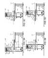
- FIGS. 5A-5Dillustrate side cut-away views of the IGRT apparatus of FIG. 3 for a plurality of different longitudinal positions of a ring gantry thereof during conical non-coplanar or cono-helical non-coplanar radiation treatment delivery;
- FIGS. 5E-5Gillustrate side cut-away views of the IGRT apparatus of FIG. 3 for a plurality of different longitudinal positions of the ring gantry during helical non-coplanar radiation treatment delivery;
- FIGS. 6A-6Dillustrate longitudinal translation of a 3D imaging device and a ring gantry structure of an IGRT system according to a preferred embodiment for providing pretreatment and/or setup imaging in conjunction with radiation treatment delivery while allowing the patient to remain stationary;
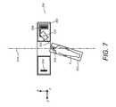
- FIG. 7illustrates a top cut-away view of an IGRT apparatus according to a preferred embodiment during an optional couch kick mode of operation
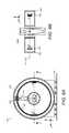
- FIGS. 8A-8Billustrate axial and top cut-away views, respectively, of an IGRT apparatus according to a preferred embodiment
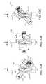
- FIGS. 9A-9Cillustrate one axial and two top cut-away views, respectively, of an IGRT apparatus according to a preferred embodiment
- FIG. 10illustrates a top cut-away view of an IGRT apparatus according to a preferred embodiment
- FIGS. 11A-11Cillustrate side cut-away views of an IGRT apparatus including a ring gantry tilted around a horizontal tilt axis at different respective tilt angles according to a preferred embodiment
- FIGS. 12A-12Cillustrate in-plane ring gantry cut-away views of the IGRT apparatus of FIGS. 11A-11C for the respective ring gantry tilt angles thereof, each including views of a radiation head thereof at two different gantry angles for illustrating dynamic inward/outward position control of the radiation head according to a preferred embodiment
- FIGS. 13A-13Cillustrate top cut-away views of an IGRT apparatus including a ring gantry tilted around a vertical tilt axis at different respective tilt angles according to a preferred embodiment
- FIGS. 14A-14Billustrate examples of conical non-coplanar and cono-helical non-coplanar radiation treatment delivery using an IGRT system according to the method of FIGS. 5A-5D ;
- FIGS. 15A-15Billustrate examples of non-coplanar radiation treatment delivery using the IGRT system of FIGS. 11A-11C ;
- FIGS. 16A-16Billustrate examples of non-coplanar radiation treatment delivery using the IGRT system of FIGS. 13A-13C .
- IGRTimage-guided radiation treatment
- IGRTimage-guided radiation therapy
- a radiation treatment apparatuscomprising a ring gantry having a central opening, a radiation treatment head coupled to the ring gantry and rotatable around the central opening in at least a 180 degree arc, and a gantry translation mechanism configured to translate the ring gantry in a direction of a longitudinal axis extending through the central opening.
- the ring gantryis housed within a ring gantry structure that has an overall length of less than about one meter along the longitudinal axis, which advantageously promotes a non-claustrophobic, “open-air” feel and experience for the patient.
- the radiation treatment headis rotatable around the central opening in a full 360 degree arc.
- the ring gantrydefines a central ring gantry plane along which a center of mass of the radiation treatment head is maintained, and the radiation treatment head is pivotably mounted to the ring gantry in a manner that allows treatment radiation to be directed out of plane relative to the ring gantry plane. More preferably, the radiation treatment head is mounted to allow further pivotable movement such that treatment radiation can be directed off-center relative to a central longitudinal axis passing through the isocenter.
- a rich variety of different treatment types and treatment profilesare made possible including, but not limited to, conical non-coplanar rotational arc therapy and cono-helical non-coplanar rotational arc therapy.
- yet another degree of freedomis provided by mounting the radiation treatment head to the ring gantry such that a radial distance between the radiation treatment head and the central longitudinal axis is dynamically controllable.
- in-treatment imagingis provided by a first kV imaging system including a first imaging source and a first imaging detector that are translatable with the ring gantry along the longitudinal axis.
- the first imaging source and first imaging detectorcan be mounted to the ring gantry to be rotatable in unison with the radiation treatment head around the central opening, or alternatively can be fixed to a frame of the ring gantry structure such that they are not rotatable around the central opening but are still translatable along the longitudinal axis with the ring gantry.
- a second kV imaging systemincluding a second imaging source and a second imaging detector are also provided, the second kV imaging system being either stationary along the longitudinal axis or independently translatable along the longitudinal axis relative to the ring gantry.
- the second kV imaging systemis fixably positioned and/or movably controlled such that, when the ring gantry is moved longitudinally such that its central plane is removed from the isocenter, the second kV imaging system can “take over” for the first kV imaging system to provide the necessary in-treatment image information.
- the treatment vaultis also outfitted with a 3D imaging device (e.g., CT, MRI) separate from the ring gantry structure containing the ring gantry and radiation treatment head, wherein the 3D imaging device is translatable along the central longitudinal axis separately and independently of the ring gantry structure.
- the ring gantry structureis translatable along the central longitudinal axis between a first location for which it longitudinally encompasses the isocenter and a second location away from the isocenter.
- the 3D imaging deviceis translatable along the central longitudinal axis between a third location for which it is away from the isocenter and a fourth location for which it longitudinally encompasses the isocenter.
- thisprovides an ability to keep the patient completely stationary while achieving both (a) pre-treatment and/or setup imaging of the target tissue volume by the 3D imaging device, and (b) delivery of radiation treatment to the target tissue volume by the radiation treatment head.
- pre-treatment and/or setup imagingthe ring gantry structure is moved out of the way while the 3D imaging device acquires the pre-treatment and/or setup images, while for delivery of radiation treatment the 3D imaging device is moved out of the way to allow the ring gantry-mounted radiation treatment head to perform radiation delivery, all without needing to translate, rotate, or otherwise move the patient.
- a radiation treatment apparatuscomprising a ring gantry having a central opening sufficiently large to accommodate a body of a patient positioned along a fixed longitudinal axis and extending therethrough, and further comprising a gantry tilting mechanism configured to tilt the ring gantry to a plurality of different tilt angles relative to the longitudinal axis.
- the apparatusfurther comprises a radiation treatment head coupled to the ring gantry and rotatable around the central opening in at least a 180 degree arc, and more preferably a complete 360 degree arc.
- the ring gantryis tiltable without being longitudinally translatable in the treatment vault, while in another preferred embodiment the ring gantry is both tiltable and longitudinally translatable in the treatment vault.
- the ring gantryis tiltable around a horizontal tilt axis, while in another preferred embodiment the ring gantry is tiltable around a vertical tilt axis.
- the tilt axiswill likewise be translatable along with the ring gantry.
- One or more kV imaging systemscan include one or more on-gantry kV imaging systems that are mounted to the ring gantry and that are therefore tiltable and/or translatable therewith.
- the one or more kV imaging systemscan further and/or alternatively include one or more independently movable kV imaging systems that move in the treatment vault independently of the ring gantry, and can further and/or alternatively include one or more fixed kV imaging systems that are fixed relative to the treatment vault.
- a mechanical coupling between the radiation treatment head and the ring gantrydesigned to facilitate and promote dynamic control of a distance by which the radiation treatment head extends inwardly toward the central opening relative to the ring gantry.
- the radiation treatment headis coupled to the ring gantry by a telescoping arm configured to dynamically extend, under computerized control, toward and away from a center of the ring gantry plane.
- the inward extension distanceis dynamically controlled as the radiation treatment head is rotated through a plurality of gantry angles around the central opening, the dynamic control being applied in a manner such that the radiation treatment head is maintained adjacently outside a predefined cylindrical buffer zone extending around the patient along the longitudinal axis.
- the tip of the radiation treatment headfollows a generally elliptical trajectory, the telescoping arm being relatively retracted at locations for which the circumference of the ring gantry comes closer to the buffer zone, the telescoping arm being relatively extended at locations for which the circumference of the ring gantry is farther away from the buffer zone.
- the treatment vaultcan also outfitted with a separate 3D imaging device (e.g., CT, MRI) translatable along the longitudinal axis separately and independently of the ring gantry structure, for providing the ability to keep the patient completely stationary while achieving both (i) pre-treatment and/or setup imaging, and (ii) delivery of radiation treatment.
- a separate 3D imaging devicee.g., CT, MRI
- FIG. 1illustrates a radiation treatment environment 100 within which one or more of the preferred embodiments is advantageously applied.
- the radiation treatment environment 100includes a reference imaging system 102 and an IGRT system 104 .
- Reference imaging system 102usually comprises a high precision volumetric imaging system such as a computed tomography (CT) system or a nuclear magnetic resonance imaging (MRI) system.
- CTcomputed tomography
- MRInuclear magnetic resonance imaging
- the reference imaging system 102is often a general purpose tool used for a variety of different purposes in the clinic or hospital environment, and is not specifically dedicated to the IGRT system 104 .
- the reference imaging system 102is often located in its own separate room or vault and is purchased, installed, and/or maintained on a separate and more generalized basis than the IGRT system 104 . Accordingly, for the example of FIG. 1 , the reference imaging system 102 is illustrated as being distinct from the IGRT system 104 . Notably, for other radiation treatment environments that are not outside the scope of the present teachings, the reference imaging system 102 can be considered as an integral component of the IGRT system 104 .
- IGRT system 104comprises a radiation treatment (MV) source 108 that selectively applies high-energy x-ray treatment radiation to a target volume of a patient P positioned on a treatment couch TC.
- the MV source 108applies the treatment radiation under the control of a system controller 114 , and more particularly a treatment radiation control subsystem 128 thereof.
- System controller 114further comprises processing circuitry 120 , a detector controller 122 , a couch position controller 124 , and a kV radiation controller 126 each programmed and configured to achieve one or more of the functionalities described further herein.
- One or more imaging (kV) radiation sources 110selectively emit relatively low-energy x-ray imaging radiation under the control of kV radiation controller 126 , the imaging radiation being captured by one or more imaging detectors 112 .
- one or more of the imaging detectors 112can be a so-called portal imaging detector that captures high-energy x-ray treatment radiation from MV source 108 that has propagated through the target volume.
- the kV imaging radiation sources 110include both a two-dimensional stereotactic x-ray imaging system and a tomosynthesis imaging system.
- a two-dimensional stereotactic x-ray imaging systemis provided, while for still other preferred embodiments only a tomosynthesis imaging system is provided.
- each of the stereotactic x-ray imaging system and the tomosynthesis imaging systemare characterized by either (a) a fixed, predetermined, nonmoving geometry relative to the (x, y, z) coordinate system of the treatment room, or (b) a precisely measurable and/or precisely determinable geometry relative to the (x, y, z) coordinate system of the treatment room in the event they are dynamically moveable.
- the MV radiation source 108should also, of course, have a precisely measurable and/or precisely determinable geometry relative to the (x, y, z) coordinate system of the treatment room.
- a couch positioner 130is actuated by the couch position controller 124 to position the couch TC.
- a non-x-ray based position sensing system 134senses position and/or movement of external marker(s) strategically affixed to the patient, and/or senses position and/or movement of the patient skin surface itself, using one or more methods that do not involve ionizing radiation, such as optically based or ultrasonically based methods.
- IGRT system 104further includes an operator workstation 116 and a treatment planning system 118 .
- FIGS. 2A-2Billustrate an IGRT system according to one or more preferred embodiments including a translatable ring gantry structure 200 .
- Ring gantry structure 200comprises a frame 202 within which is disposed a ring gantry 204 .
- a radiation treatment head 210such as and without limitation a linear accelerator (LINAC) or a compact proton source, which includes thereon an end collimator 212 , such as a multi-leaf collimator (MLC), and which provides a therapeutic radiation beam 203 .
- the radiation treatment head 210is mounted to the ring gantry 204 by a mount 206 that includes an arm 207 .
- LINAClinear accelerator
- MLCmulti-leaf collimator
- the radiation treatment head 210comprises a compact lightweight LINAC, such as an X-band or C-band LINAC in a compact configuration without a bending magnet.
- a compact lightweight LINACsuch as an X-band or C-band LINAC in a compact configuration without a bending magnet.
- the compact acceleratorcan include a bending magnet.
- the ring gantry 204 and radiation treatment head 210are configured such that the radiation treatment head 210 is rotatable around a longitudinally oriented central axis 214 passing through an isocenter 216 .
- Any of a variety of different mechanismscan be used to achieve such rotating functionality, including mechanisms in which the ring gantry 204 is fixed while the mount 206 slides or rolls therearound, mechanisms in while the entire ring gantry 204 rotates and the mount 206 is affixed to a single point thereon, and various combinations thereof.
- gantry anglemay still be used to represent the angular disposition of the radiation treatment head relative to the central longitudinal axis as viewed axially from an end of the device, even though the ring gantry itself is not rotating and instead the radiation treatment head is being translated circumferentially therearound.
- the ring gantry 204 and radiation treatment head 210are configured and dimensioned so as to allow a central opening (central bore) 218 to exist, that is, an opening sufficient to allow a patient P to be positioned therethrough without the possibility of being incidentally contacted by the radiation treatment head 210 or other mechanical components as it rotates about patient P.
- a shielding structure 220is provided to line the boundary of the central bore 218 as well as to cover the sides of ring gantry structure 200 .
- the shielding structure 220can reduce the sense of intimidation that the patient might feel in view of the large moving parts in the device.
- the shielding structure 220provides the ability to maximize the rotation speed of the gantry, while still meeting all regulatory safety requirements.
- the shielding structure 220should be formed of a material that is substantially transparent to the therapeutic and imaging radiation, and optionally can be visibly opaque as well.
- the central bore 218could alternatively be termed a cylindrical buffer zone, or perhaps more colloquially a “no-fly zone,” the alternative terminology being particularly appropriate for instances in which the shielding structure 220 is not included.
- a transverse isocentric plane 217Associated with the IGRT system is an imaginary plane, termed herein a transverse isocentric plane 217 , that is orthogonal to the rotation axis 214 and passes through the isocenter 216 .
- a transverse isocentric plane 217Associated with the ring gantry structure 200 including ring gantry 204 is a ring gantry plane 219 which, while it may at certain times and/or for certain procedures remain coplanar with the transverse isocentric plane 217 as illustrated in FIG. 2A , can become separated in the longitudinal direction from the transverse isocentric plane 217 by a translation of the ring gantry structure 202 in the longitudinal direction.
- an isocenteris a fixed physical point in a treatment room (treatment vault).
- a treatment centeris a point within a target volume of the patient defined by a physician during treatment planning, normally based on a pretreatment image reference frame.
- the treatment centeris aligned with the isocenter during a set up procedure.
- the isocenter 216remains at a fixed point in the treatment vault, and it is the ring gantry plane 219 that varies in longitudinal position.
- FIGS. 2A-2BIllustrated in FIGS. 2A-2B is a translational actuation mechanism 240 for translating the ring gantry structure 200 in the longitudinal direction. While shown by way of simplified example in FIGS. 2A-2B as wheels that may be driven by a motor (not shown), the translational actuation mechanism 240 can take on a variety of different forms, as would be apparent to a person skilled in the art in view of the present disclosure, to achieve such translational functionality. It should also be appreciated that, while shown as being rollably disposed on a floor 226 of a treatment vault, the ring gantry structure 200 can alternatively, or in conjunction therewith, be translatably coupled to the ceiling and/or one or more side walls of the treatment vault.
- a patient couch 222is provided for supporting the patient P, the patient couch 222 preferably being coupled to an automated patient positioning system 224 capable of manipulating the patient with three or more degrees of freedom (e.g., three orthogonal translations, one parallel to the rotation axis 214 , two orthogonal to rotation axis 214 , plus optionally one or more rotations).
- three or more degrees of freedome.g., three orthogonal translations, one parallel to the rotation axis 214 , two orthogonal to rotation axis 214 , plus optionally one or more rotations.
- the ring gantry structure 200provides a high degree of patient visibility into the surrounding room to provide a less claustrophobic experience.
- shielding structure 220could be a structural supporting cylinder or hub to which frame 202 is mechanically connected at approximately opposite ends of the supporting cylinder or hub.
- the hubwill provide additional or alternative structural support in addition to or in lieu of frame 202 .
- the hub (whether or not made from radiolucent material) and/or the shielding structure 220has a longitudinal slit along the central opening 218 parallel to rotation axis 214 to allow radiation to pass therethrough unimpeded, thereby reducing the possibility of the so-called skin effect or to maximize skin sparing.
- the shielding structure 220could still line the structural cylinder and need not necessarily possess the slit, thereby fully closing off patient view and access to the rotating radiation source.
- the slitif viewable by a patient, could be constructed so as to minimize potential access to the rotating radiation source, and the patient would likely only see the rotating radiation source when it is at or near the top of the ring pointing approximately vertically down.
- the hubwill rotate in approximate unison with the radiation head.
- the shielding structure 220can be coupled such that it rotates with the ring gantry 204 .
- a removable covercan be provided to “plug” the slit, which would be fitted for rotational therapy treatment.
- the slitis kept open.
- the plugis fitted into the slit. This can be achieved manually in pre-treatment with a totally removable plug, or alternatively there is provided a mechanically sliding system on the shielding structure 220 that can cover and uncover the slit under control and/or actuation of the treatment technician.
- the radiation treatment head 210is preferably coupled to the arm 207 of the mount 206 in a manner that allows pivoting of the radiation treatment head 210 around a first pivot axis M 1 , termed herein a primary pivot axis, and (iii) pivoting of the therapeutic radiation head 210 around a second axis M 2 , termed herein a secondary pivot axis, located at a right angle to M 1 .
- the axes M 1 and M 2each pass through the center of mass (CoM) of the therapeutic radiation head 210 (which is also coincident with the radiation source, e.g., the focal spot in a LINAC), the center of mass lies along the axis of the therapeutic radiation beam 203 , and the center of mass is coincident with the ring gantry plane 219 .
- the primary pivoting around axis M 1 and the secondary pivoting around axis M 2can be considered as a gimbal or gimballing motion of the therapeutic radiation head 210 .
- the primary pivoting around axis M 1may be referenced hereinbelow by the term “M 1 pivot” or “M 1 pivoting”
- the secondary pivoting around axis M 2may be referenced hereinbelow by the term “M 2 pivot” or “M 2 pivoting.”
- the terms primary/M 1 and secondary/M 2are used herein for identification purposes and are not indicative of any particular imaging-related or treatment-related relative rankings.
- pivoting around the M 2 axisallows for treatment radiation to be directed out of plane relative to the ring gantry plane 219 .
- the mount 206 and arm 207are configured to allow controllable shortening and lengthening of the distance between the radiation treatment head 210 and the ring gantry 204 .
- the arm 207can be, for example, a telescoping arm.
- the radial distance between the radiation treatment head 210 and the central longitudinal axis 214is dynamically controllable. This capability can be advantageously used prevent collisions between the MLC 212 and the shielding structure 220 at locations along the central bore 218 when the radiation treatment head 210 is pivoted around the M 2 pivot axis.
- thiscan advantageously relax certain design constraints, such allowing the central bore 218 to be larger than it would otherwise be while also allowing substantial M 2 -axis pivoting freedom of the radiation treatment head 210 .
- the radial distance between the radiation treatment head 210 and the central longitudinal axis 214is fixed and not dynamically controllable.
- FIGS. 2A-2Bis a first kV imaging system S 1 /D 1 comprising an imaging source 51 and an imaging detector D 1 coupled to the ring gantry 204 to be rotatable and translatable therewith.
- the first kV imaging system S 1 /D 1is translatable with the ring gantry 204 but is either fixably attached to the frame 202 or otherwise uncoupled with the rotations of the ring gantry 204 .
- the first kV imaging system S 1 /D 1can generally have any of a variety of different hardware components (e.g., single x-ray source, source array, etc.) and two- or three-dimensional imaging schemes (e.g., 2D stereoscopic imaging, CBCT, tomosynthesis, etc.) without departing from the scope of the present teachings.
- the imaging source S 1comprises a source array that uses a computer-steerable electron beam and a spatial arrangement of metallic targets, such as one or more such devices developed by Triple Ring Technologies, supra
- the imaging detector D 1is a digital array detector, and a 3D tomosynthesis in-treatment imaging functionality is provided.
- the IGRT system of FIGS. 2A-2Bfurther includes a plurality of actuators of various types (not shown) for achieving the mechanical functionalities described hereinabove and hereinbelow in the instant disclosure.
- the IGRT systemincludes respective actuation devices (not shown) to achieve the rotation of the ring gantry 204 around the rotation axis 214 , the radial translation of the radiation treatment head 210 inwardly and outwardly from the central longitudinal axis 214 , the M 1 and M 2 pivoting of the radiation treatment head 210 , and the translation of the ring gantry structure 200 along the direction of the longitudinal axis.
- the IGRT systemfurther includes one or more processing and/or control units, such as may be implemented on one or more programmable computers, for controlling the various actuators and sending signals to and from the various recited radiation sources and detectors as necessary to achieve the functionalities described hereinabove and hereinbelow in the instant disclosure.
- processing and/or control unitssuch as may be implemented on one or more programmable computers, for controlling the various actuators and sending signals to and from the various recited radiation sources and detectors as necessary to achieve the functionalities described hereinabove and hereinbelow in the instant disclosure.
- FIGS. 3A-3Billustrate the IGRT system of FIGS. 2A-2B with annotations that more clearly depict the several degrees of freedom of the radiation treatment head 210 that are advantageously provided.
- the radiation treatment head 210is rotatable around the central axis 214 (arrow 302 ), translatable along the longitudinal direction (arrow 304 ), pivotable around the M 1 axis (arrow 306 ), pivotable around the M 2 axis (arrow 308 ), and radially translatable relative to the central axis 214 (arrow 310 ).
- a rich variety of radiation treatment delivery plansare facilitated.
- FIG. 4illustrates the ring gantry structure 200 as coupled to and/or integrated with a computer system 449 using one or more busses, networks, or other communications systems 460 , including wired and/or wireless communications systems, and being capable in conjunction therewith of implementing the methods of one or more of the preferred embodiments.
- Methods of image guided radiation treatment in accordance with one or more of the preferred embodimentsmay be implemented in machine readable code (i.e., software or computer program product) and performed on computer systems such as, but not limited to, the computer system 449 , wherein a central processing unit (CPU) 451 including a microprocessor 452 , random access memory 453 , and nonvolatile memory 454 (e.g., electromechanical hard drive, solid state drive) is operated in conjunction with various input/output devices, such as a display monitor 455 , a mouse 461 , a keyboard 463 , and other I/O devices 456 capable of reading and writing data and instructions from machine readable media 458 such as tape, compact disk (CD), digital versatile disk (DVD), blu-ray disk (BD), and so forth.
- machine readable codei.e., software or computer program product
- computer systemssuch as, but not limited to, the computer system 449 , wherein a central processing unit (CPU) 451 including a microprocessor
- Software to control the image guided radiation treatment steps described hereinmay be implemented as a program product and stored on a tangible storage device such as the machine readable medium 458 , an external nonvolatile memory device 462 , or other tangible storage medium.
- a tangible storage devicesuch as the machine readable medium 458 , an external nonvolatile memory device 462 , or other tangible storage medium.
- FIG. 4is omitted from further drawings and/or descriptions hereinbelow. Methods for configuring and programming the computer system 449 for achieving the functionalities described herein would be apparent to a person skilled in the art in view of the present disclosure.
- FIGS. 5A-5Dillustrate the IGRT system of FIGS. 2A-4 supra for different longitudinal positions of the ring gantry structure 200 (x( 1 ), x( 2 ), x( 3 ), and x( 4 )) relative to the treatment vault.
- the distance between the radiation treatment head 210 and the ring gantry 204can be varied to different amounts (d 1 , d 2 , d 3 , and d 4 , respectively) to avoid collisions between the MLC 212 and the shielding structure 220 , and/or for other advantageous purposes.
- the IGRT apparatusis operated to apply non-coplanar radiation treatment, comprising rotating the radiation treatment head 210 around the longitudinal axis 214 to a plurality of different gantry angles, and translating the ring gantry structure 200 including ring gantry 204 to a plurality of different longitudinal positions along the longitudinal axis 214 .
- the patientcan remain stationary relative to the treatment vault and does not need to be moved.
- the plurality of different longitudinal positionsincludes many for which the ring gantry plane 219 is not coincident with the isocenter (or, more generally, the treatment center), and for such positions the radiation treatment head 210 is pivoted to direct treatment radiation out of the ring gantry plane 219 and toward the treatment center, whereby conical non-coplanar radiation treatment and/or cono-helical non-coplanar radiation treatment can be delivered.
- the radiation treatment head 210can also be pivoted to direct treatment radiation off-center relative to the longitudinal axis 214 as may be needed for the particular treatment plan, motion compensation, and so forth.
- FIGS. 14A-14Billustrate non-coplanar rotational arc therapy profiles that can result from the operation of the IGRT apparatus as shown in FIGS. 5A-5D .
- the ring gantry 204(and, therefore, the radiation treatment head 210 ) is longitudinally translated in discrete steps, with a rotation of the ring gantry 204 occurring at each step.
- each discrete cone shape 1 - 5corresponding to a different translational step of the radiation treatment head 210 .
- the ring gantry 204(and, therefore, the radiation treatment head 210 ) is continuously translated in the longitudinal direction as the ring gantry 204 is rotated.
- FIG. 14Billustrates a cross-section of the resultant delivery profile for cono-helical non-coplanar rotational arc therapy, which spans the same conical three-dimensional volume as conical non-coplanar rotational arc therapy, but which does so in a continuous or helical manner.
- FIGS. 5E-5Gillustrate side cut-away views of the IGRT apparatus of FIGS. 2A-4 for a plurality of different longitudinal positions of the ring gantry for what can be termed helical non-coplanar radiation treatment delivery, helical non-coplanar rotational arc therapy, or helical tomotherapy.
- the radiation treatment delivery provided in the example of FIGS. 5E-5Gcan achieve the same or substantially the same delivery profile as the helical tomotherapy provided by the HI-ART® treatment system commercially available from TomoTherapy Incorporated of Madison, Wis., while at the same time advantageously removing the need to move the patient. As illustrated in FIGS.
- the ring gantry 204is translated to different longitudinal positions for which the ring gantry plane 219 is not coincident with the isocenter (or, more generally, the treatment center), but for such positions the radiation treatment head 210 is not pivoted out of the ring gantry plane 219 .
- the resultant delivery profile(not shown) takes on a helical or spiral shape.
- any of the IGRT systems of the present disclosurewould also, of course, be capable of delivering coplanar radiation treatment delivery or coplanar arc therapy by not using the ring gantry translation and/or ring gantry tilting capabilities described herein.
- FIGS. 6A-6Dillustrate an IGRT system according to a preferred embodiment that provides an ability to keep the patient completely stationary while achieving both (a) pre-treatment and/or setup imaging of the target tissue volume using a high-quality 3D imaging device, and (b) delivery of radiation treatment to the target tissue volume by the radiation treatment head.
- the treatment vault of the IGRT systemincludes a 3D imaging device 602 (e.g., CT, MRI) separate from the ring gantry structure 200 containing the ring gantry 204 and radiation treatment head 210 .
- a 3D imaging device 602e.g., CT, MRI
- the 3D imaging device 602is translatable, such as by a translation mechanism 604 , along the central longitudinal axis 214 separately and independently of the ring gantry structure 200 .
- the ring gantry structure 200is translatable along the central longitudinal axis 214 between a first location L 1 for which it longitudinally encompasses the isocenter 216 and a second location L 2 away from the isocenter.
- the 3D imaging device 602is translatable along the central longitudinal axis 214 between a third location L 3 away from the isocenter and a fourth location L 4 for which it longitudinally encompasses the isocenter.
- the ring gantry structureis moved out of the way while the 3D imaging device acquires the pre-treatment and/or setup images ( FIGS. 6A-6B ), while for delivery of radiation treatment the 3D imaging device is moved out of the way to allow the ring gantry-mounted radiation treatment head to perform radiation delivery ( FIGS. 6C-6D ), all without needing to translate, rotate, or otherwise move the patient.
- the 3D imaging deviceacquires the pre-treatment and/or setup images
- the 3D imaging deviceis moved out of the way to allow the ring gantry-mounted radiation treatment head to perform radiation delivery ( FIGS. 6C-6D ), all without needing to translate, rotate, or otherwise move the patient.
- any of a variety of different mechanical translation schemes and mounting schemescan be used achieving the translation functionality of the 3D imaging device (e.g., ceiling rails, wall rails, floor rails, etc.)
- FIG. 7illustrates using a so-called “couch kick” (varying the angle of the patient couch 222 relative to the longitudinal axis 214 ) in an optional mode of operation particularly useful for certain cranial treatments.
- a wide variety of orientations and configurationsare made available for directing radiation beams into the head at various angles of attack.
- FIG. 8Aillustrates the same side cross-sectional view of the ring gantry structure 200 of FIG. 2B , supra, while FIG. 8B illustrates a top cross-sectional view (i.e., a cross-sectional view as seen from the ceiling of the treatment vault) of the ring gantry structure 200 .
- a first kV imaging system S 1 /D 1that is mounted on the ring gantry 204 and is therefore rotatable and translatable therewith.
- the first kV imaging system S 1 /D 1will likewise no longer be directed toward imaging at the isocenter 216 .
- FIGS. 9A-9C and FIG. 10illustrate IGRT systems according to alternative preferred embodiments, wherein in-treatment imaging at the isocenter 216 can still be achieved even where the ring gantry plane 219 is positioned off-isocenter.
- a second kV imaging system D 2 /S 2 including a second imaging source S 2 and a second imaging detector D 2are provided.
- the second kV imaging system D 2 /S 2is configured for imaging at the isocenter 216 and is fixed relative to the treatment vault using the fixed imaging mounts 952 and 954 . As illustrated in FIG.
- the second kV imaging system D 2 /S 2can “take over” for the first kV imaging system D 1 /S 1 to provide the necessary in-treatment image information.
- the second kV imaging system S 2 /D 2can be movable in the longitudinal direction relative to the treatment vault independently of the ring gantry structure 200 . As illustrated in another preferred embodiment shown in FIG.
- a second kV imaging systemcan take on any of a variety of different configurations, such as the use of dual source arrays S 2 a /S 2 b mounted on fixed pads 952 a / 952 b and dual detector arrays D 2 a /D 2 b mounted on fixed pads 954 a / 954 b in a stereoscopic configuration.
- the second kV imaging systemcan be movable relative to the treatment vault in any of a variety of different ways while remaining uncoupled with the longitudinal movement of the ring gantry structure 200 , for the purpose of obtaining a better configuration for in-treatment imaging at the isocenter 216 .
- FIGS. 11A-11Cillustrate side cut-away views of an IGRT apparatus including a ring gantry tilted around a horizontal tilt axis at different respective tilt angles according to a preferred embodiment.
- IGRT apparatus 1100includes a ring gantry structure 1102 including a ring gantry 1104 .
- the ring gantry structure 1102 and ring gantry 1104are coupled such that they are jointly tiltable (and/or translatable) and therefore such tilting (or translation) is described hereinbelow for the ring gantry only, it being understood that the ring gantry structure 1102 will so tilt (and/or translate) with the ring gantry 1104 .
- the ring gantry 1104has a central opening sufficiently large to accommodate a body of a patient positioned along a longitudinal axis 1114 and extending therethrough.
- a gantry tilting mechanism 1170 / 1172is provided that is configured to tilt the ring gantry 1104 around a horizontal tilt axis 1177 to a plurality of different tilt angles relative to the longitudinal axis 1114 .
- the ring gantry 1104defines a ring gantry plane 1119 .
- a radiation treatment head 1110is coupled to the ring gantry 1104 and is rotatable around a center of the ring gantry plane 1119 in at least a 180 degree arc, and preferably a 360 arc.
- the radiation treatment head 1110is mechanically coupled to the ring gantry such that a distance “d” by which the radiation treatment head extends inwardly toward the central opening relative to the ring gantry is dynamically controllable, with the distance “d” being d 1 for the tilt of FIG. 11A , d 2 for the non-tilted scenario of FIGS. 11B , and d 3 for the tilt of FIG. 11C .
- the mechanical couplingcan be based, for example, on the use of a telescoping arm 1107 of a mount 1106 that is connected to the ring gantry 1104 .
- the radiation treatment head 1110is coupled to the telescoping arm 1107 in a manner that allows pivoting around multiple pivot axes such that treatment radiation can be directed off-center relative to the longitudinal axis 1114 and/or out-of-plane relative to the ring gantry plane 1119 .
- the IGRT system 1100 of FIGS. 11A-11Cfurther includes a plurality of actuators of various types (not shown) for achieving the mechanical functionalities described hereinabove and hereinbelow in the instant disclosure.
- the gantry tilting mechanism 1170 / 1172includes a raisable, lowerable, and translatable floor pivot structure 1170 configured to operate in unison with a lowerable, raisable, and translatable ceiling pivot structure 1172 for achieving the described tilting functionality around the horizontal tilt axis 1177 .
- the IGRT systemfurther includes one or more processing and/or control units, such as may be implemented on one or more programmable computers, for controlling the various actuators and sending signals to and from the various recited radiation sources and detectors as necessary to achieve the functionalities described hereinabove and hereinbelow in the instant disclosure.
- processing and/or control unitssuch as may be implemented on one or more programmable computers, for controlling the various actuators and sending signals to and from the various recited radiation sources and detectors as necessary to achieve the functionalities described hereinabove and hereinbelow in the instant disclosure.
- FIGS. 12A-12Cillustrate in-plane cut-away views of the IGRT apparatus of FIGS. 11A-11C when viewed in the ring gantry plane 1119 for each of the respective ring gantry tilt angles thereof. Included in each of FIGS. 12A-12C are views of the radiation treatment head 1110 at two different gantry angles for illustrating the preferred dynamic inward/outward position control of the radiation treatment head 1110 relative to the ring gantry 1104 .
- the distance “d” by which the radiation treatment head 1110 extends inwardly from the ring gantry 1104 as the radiation treatment head 1110 is rotated through a plurality of gantry anglesis dynamically controlled such that the radiation treatment head 1110 is maintained adjacently outside a predefined cylindrical buffer zone 1118 (“no-fly zone”) extending around and along the longitudinal axis 1114 .
- no-fly zonea predefined cylindrical buffer zone 1118
- the in-gantry-plane trajectory of the radiation treatment head 1110is elliptical (see ellipses eA and eC, respectively) in order to be maintained at or just outside the cylindrical buffer zone 1118 .
- the cylindrical buffer zone 1118corresponds to the outer dimensions of the center bore shield.
- the IGRT system 1100is configured to achieve a ring gantry tilt angle of at least 30 degrees while maintaining a suitably sized cylindrical buffer zone 1118 .
- the IGRT system 1100is configured to achieve a ring gantry tilt angle of at least 45 degrees while maintaining a suitably sized cylindrical buffer zone 1118 , and in still another preferred embodiment is configured to achieve a ring gantry tilt angle of at least 60 degrees while maintaining a suitably sized cylindrical buffer zone 1118 .
- US07188999B2discusses one proposal that could at least partially address the problem of maintaining some sort of no-fly zone around the patient when the arc-shaped guide rail is tilted off-normal relative to the longitudinal axis, that proposal is to actuably elevate the entire gantry structure, including the entire arc-shaped guide rail, to different elevations above the floor of the treatment room.
- the horizontal tilt axis 1177is generally normal to the longitudinal axis 1114 .
- the longitudinal axis 1114passes through an isocenter 1116 (or, more generally, a treatment center).
- the gantry tilting mechanism 1170 / 1172can be configured to also serve as a gantry translation mechanism capable of translating the entire ring gantry 1104 in a direction of a the longitudinal axis.
- the horizontal tilt axis 1177is likewise correspondingly movable in the longitudinal direction.
- FIGS. 11A-11CAlso provided in conjunction with the IGRT system 1100 of FIGS. 11A-11C , as well as the IGRT system 1300 of FIGS. 13A-13C infra are one or more kV imaging systems analogous to those illustrated in FIGS. 8A-10 and described in the context of the IGRT systems of FIGS. 2A-5G , which description need not be repeated here.
- the treatment vaultcan be outfitted with an independently translatable 3D imaging system and with a separate 3D imaging device (e.g., CT, MRI) translatable along the longitudinal axis separately and independently of the ring gantry structure, for providing the ability to keep the patient completely stationary while achieving both (i) pre-treatment and/or setup imaging, and (ii) delivery of radiation treatment, in a manner analogous to that illustrated in FIGS. 6A-6D and described in the context of the IGRT systems of FIGS. 2A-5G , which description need not be repeated here.
- a separate 3D imaging devicee.g., CT, MRI
- FIGS. 13A-13Cillustrate top cut-away views of an IGRT apparatus 1300 according to a preferred embodiment, the IGRT apparatus 1300 having similar capabilities as the IGRT apparatus 1100 of FIG. 11 , supra, except that the ring gantry is tiltable around a vertical axis rather than a horizontal axis.
- IGRT apparatus 1300includes a ring gantry structure 1302 including a ring gantry 1304 having has a central opening sufficiently large to accommodate a body of a patient positioned along a longitudinal axis 1314 and extending therethrough.
- a gantry tilting mechanism(not shown) is provided that is configured to tilt the ring gantry 1304 around a vertical tilt axis 1377 to a plurality of different tilt angles relative to the longitudinal axis 1114 .
- a radiation treatment head 1310is coupled to the ring gantry 1304 and is rotatable around a center of a ring gantry plane 1319 , and is mechanically coupled to the ring gantry 1304 such that a distance “d” by which the radiation treatment head extends inwardly toward the central opening relative to the ring gantry is dynamically controllable, with the distance “d” being d 1 for the tilt of FIG.
- the mechanical couplingcan be based, for example, on the use of a telescoping arm 1307 of a mount 1306 that is connected to the ring gantry 1304 .
- the radiation treatment head 1310is coupled to the telescoping arm 1307 in a manner that allows pivoting around multiple pivot axes such that treatment radiation can be directed off-center relative to the longitudinal axis 1314 and/or out-of-plane relative to the ring gantry plane 1319 .
- the vertical tilt axis 1377is generally normal to the longitudinal axis 1314 . For one preferred embodiment, which is illustrated in FIGS.
- the longitudinal axis 1314passes through an isocenter 1316 (or, more generally, a treatment center).
- the gantry tilting mechanism(not shown) can be configured to also serve as a gantry translation mechanism capable of translating the entire ring gantry 1304 in a direction of a the longitudinal axis, and for such case the vertical tilt axis 1377 is likewise correspondingly movable in the longitudinal direction.
- a method for image guided radiation treatment of a body part of a patient based on the IGRT system 1100 (horizontal tilt) or 1300 (vertical tilt)can proceed as follows.
- the patientis positioned along a longitudinal axis 1114 / 1314 of the IGRT apparatus 1100 / 1300 .
- the IGRT apparatusis operated to apply non-coplanar radiation treatment to the body part during a treatment fraction, the operating comprising rotating the radiation treatment head 1110 / 1310 to a plurality of different gantry angles, the operating further comprising tilting the ring gantry 1104 / 1304 to a plurality of different tilt angles relative to the longitudinal axis 1114 / 1314 .
- the distance by which the radiation treatment head 1110 / 1310 extends inwardlyis dynamically controlled such that the radiation treatment head 1110 / 1310 is maintained adjacently outside a predefined cylindrical buffer zone 1118 / 1318 extending around the patient along the longitudinal axis.
- the predefined cylindrical buffer zone 1118 / 1318can be a circularly cylindrical shape, an elliptically cylindrical shape, or alternatively there can be provided a buffer zone around the patient that has any of a variety of different shapes, including shapes that vary with distance along the longitudinal axis.
- the radiation treatment head 1110 / 1310can be pivoted around at least two pivot axes such that treatment radiation can be directed out of the ring gantry plane 1119 / 1319 and/or directed off-center relative to the longitudinal axis 1114 / 1314 as may be needed for the particular treatment plan, motion compensation, and so forth.
- FIGS. 15A-15Billustrate examples of non-coplanar radiation treatment delivery using the IGRT system 1100 of FIGS. 11A-11C
- FIGS. 16A-16Billustrate examples of non-coplanar radiation treatment delivery using the IGRT system 1300 of FIGS. 13A-13C
- the gantry angleis actuated (in discrete steps or continuously) through one full rotation for each discrete ring gantry tilt angle (horizontal tilt angle and vertical tilt angle, respectively, for FIGS. 15A and 16A ).
- the tilt angleis progressively varied (in discrete steps or continuously) as the gantry angle is actuated (in discrete steps or continuously) through successive rotations.
- IGRTIGRT
- Such possibilitiesinclude, but are not limited to: single or parallel opposed static beams with rectangular field shaping and 1D (wedge or virtual wedge using MLC) intensity modulation; static beams with rectangular field shaping and 1D modulation; coplanar rotational treatments (“arc therapy”) with rectangular field shaping and 1D modulation; coplanar or non-coplanar beams with irregular field shaping and 1D modulation (“conformal radiation therapy” or CRT); coplanar or non-coplanar beams with irregular field shaping and 2D modulation (“intensity modulated radiation therapy” or IMRT); and tomotherapy (helical or sequential) with coplanar rotation using a narrow beam in combination with couch movement and 2D modulation.
- Such possibilitiesfurther include rotational arc therapy, also called intensity modulated arc therapy (IMAT), including one or more coplanar rotations, irregular field shaping, and 2D modulation, with gantry rotation speed, dose rate, MLC positions, and in some cases collimator angles being varied during rotation, and including multiple rotations that increase the achievable degree of intensity modulation in view of practical constraints on MLC motion during treatment.
- IMATintensity modulated arc therapy
- an IGRT system(not shown) that is similar to that of FIGS. 2A-3B , including a radiation treatment head movably coupled to a circular ring gantry in a manner that allows extension toward and retraction away from the central longitudinal axis (see arrow 310 in FIG. 3B ), such as by a telescoping arm coupling, but wherein the x-axis translation ability of the ring gantry is omitted.
- a radiation treatment headmovably coupled to a circular ring gantry in a manner that allows extension toward and retraction away from the central longitudinal axis (see arrow 310 in FIG. 3B ), such as by a telescoping arm coupling, but wherein the x-axis translation ability of the ring gantry is omitted.
- the radiation treatment headwill be able to traverse any of a variety of different circular and non-circular trajectories for achieving any of a variety of different goals.
- the ability to adjust the source-axis distance (SAD)allows an advantage of being able to adjust the radiation treatment field size, which changes proportionally to distance, as well as the effective dose rate (in MU/min) at the target location.
- small targetse.g., the trigeminal nerve root
- MLCe.g., a 10 cm ⁇ 12 cm MLC
- the ability to actuably vary the SADcan also be useful for accommodating obese patients or adjusting for very thin patients.
- the ability to dynamically vary the SAD during gantry rotationcan also be advantageously useful for accommodating “couch kicks” or other orientations in which the patient's body is not perpendicular to the ring gantry plane, for which cases elliptical orbits or other non-circular orbits may advantageously allow for the possibility of such orientations and a variety of additional associated non-coplanar delivery angles for the gantry-based system.
- dynamic control of the inward/outward extension of the radiation treatment headis indeed particularly advantageous when that control is applied during a treatment fraction as the gantry is rotated (either continuously or in discrete steps)
- the dynamic control of the radiation treatment headis not limited as such, and therefore in some preferred embodiments such dynamic control can be applied just once (e.g., prior to treatment delivery, or during one of the treatment fractions before commencing gantry rotation and/or beam activation, for example to accommodate an obese patient) while remaining within the scope of the present teachings and while still constituting dynamic control as that term is used herein.
- the imaging systemcan be provided as a portal imaging system, in which an imaging detector is provided opposite the therapeutic radiation source relative to the isocenter.
Landscapes
- Health & Medical Sciences (AREA)
- Engineering & Computer Science (AREA)
- Life Sciences & Earth Sciences (AREA)
- Biomedical Technology (AREA)
- Nuclear Medicine, Radiotherapy & Molecular Imaging (AREA)
- Veterinary Medicine (AREA)
- Public Health (AREA)
- General Health & Medical Sciences (AREA)
- Animal Behavior & Ethology (AREA)
- Pathology (AREA)
- Radiology & Medical Imaging (AREA)
- Medical Informatics (AREA)
- Physics & Mathematics (AREA)
- Heart & Thoracic Surgery (AREA)
- Molecular Biology (AREA)
- Surgery (AREA)
- High Energy & Nuclear Physics (AREA)
- Biophysics (AREA)
- Optics & Photonics (AREA)
- Pulmonology (AREA)
- Theoretical Computer Science (AREA)
- Automation & Control Theory (AREA)
- Robotics (AREA)
- Radiation-Therapy Devices (AREA)
Abstract
Description
Claims (45)
Priority Applications (12)
| Application Number | Priority Date | Filing Date | Title |
|---|---|---|---|
| US13/088,321US8536547B2 (en) | 2011-01-20 | 2011-04-15 | Ring gantry radiation treatment delivery system with dynamically controllable inward extension of treatment head |
| CN201280010985.5ACN103517737B (en) | 2011-01-20 | 2012-01-10 | Radiation Therapy Delivery System with Ring Gantry |
| EP17199454.4AEP3299064A1 (en) | 2011-01-20 | 2012-01-10 | Radiation treatment delivery system with ring gantry |
| JP2013550494AJP6109748B2 (en) | 2011-01-20 | 2012-01-10 | Radiotherapy delivery system with ring gantry |
| CN201610218017.3ACN105879245B (en) | 2011-01-20 | 2012-01-10 | Radiotherapy device and method for controlling IGRT device |
| EP12700904.1AEP2665519B1 (en) | 2011-01-20 | 2012-01-10 | Radiation treatment delivery system with ring gantry |
| PCT/US2012/020795WO2012099747A2 (en) | 2011-01-20 | 2012-01-10 | Radiation treatment delivery system with ring gantry |
| CN201610217403.0ACN105816195B (en) | 2011-01-20 | 2012-01-10 | Radiotherapy device and method for performing IGRT on body part of patient |
| JP2016082013AJP6415473B2 (en) | 2011-01-20 | 2016-04-15 | Radiotherapy delivery system with ring gantry |
| JP2016082014AJP6411401B2 (en) | 2011-01-20 | 2016-04-15 | Radiotherapy delivery system with ring gantry |
| JP2018187176AJP6960896B2 (en) | 2011-01-20 | 2018-10-02 | Radiation therapy delivery system with ring gantry |
| JP2020099775AJP2020151503A (en) | 2011-01-20 | 2020-06-09 | Radiation treatment delivery system with ring gantry |
Applications Claiming Priority (2)
| Application Number | Priority Date | Filing Date | Title |
|---|---|---|---|
| US201161434824P | 2011-01-20 | 2011-01-20 | |
| US13/088,321US8536547B2 (en) | 2011-01-20 | 2011-04-15 | Ring gantry radiation treatment delivery system with dynamically controllable inward extension of treatment head |
Publications (2)
| Publication Number | Publication Date |
|---|---|
| US20120189102A1 US20120189102A1 (en) | 2012-07-26 |
| US8536547B2true US8536547B2 (en) | 2013-09-17 |
Family
ID=46544173
Family Applications (2)
| Application Number | Title | Priority Date | Filing Date |
|---|---|---|---|
| US13/088,321Active2031-09-19US8536547B2 (en) | 2011-01-20 | 2011-04-15 | Ring gantry radiation treatment delivery system with dynamically controllable inward extension of treatment head |
| US15/614,039Active2032-06-12US10610175B2 (en) | 2011-01-20 | 2017-06-05 | Radiation treatment delivery system with translatable ring gantry |
Family Applications After (1)
| Application Number | Title | Priority Date | Filing Date |
|---|---|---|---|
| US15/614,039Active2032-06-12US10610175B2 (en) | 2011-01-20 | 2017-06-05 | Radiation treatment delivery system with translatable ring gantry |
Country Status (5)
| Country | Link |
|---|---|
| US (2) | US8536547B2 (en) |
| EP (2) | EP3299064A1 (en) |
| JP (5) | JP6109748B2 (en) |
| CN (3) | CN103517737B (en) |
| WO (1) | WO2012099747A2 (en) |
Cited By (58)
| Publication number | Priority date | Publication date | Assignee | Title |
|---|---|---|---|---|
| US20120230465A1 (en)* | 2011-03-09 | 2012-09-13 | Toshiba Medical Systems Corporation | X-ray ct device |
| US20130208866A1 (en)* | 2012-02-09 | 2013-08-15 | Per Harald Bergfjord | Methods and Apparatus for Providing Accessories to a Patient During Radiation Treatment |
| US20140270090A1 (en)* | 2013-03-15 | 2014-09-18 | Proto Manufacturing Ltd. | X-Ray Diffraction Apparatus And Method |
| US20140288348A1 (en)* | 2013-03-25 | 2014-09-25 | Siemens Aktiengesellschaft | Radiotherapy treatment device comprising image acquisition device and irradiation device, and radiotherapy method |
| US20150073256A1 (en)* | 2010-02-24 | 2015-03-12 | Accuray Incorporated | Gantry image guided radiotherapy system and related treatment delivery methods |
| US9097384B1 (en) | 2011-11-30 | 2015-08-04 | Sun Nuclear Corporation | Support apparatus for radiotherapy measurement system |
| US9205281B2 (en) | 2008-03-14 | 2015-12-08 | Reflexion Medical, Inc. | Method and apparatus for emission guided radiation therapy |
| US9283403B2 (en) | 2011-03-31 | 2016-03-15 | Reflexion Medical, Inc. | Systems and methods for use in emission guided radiation therapy |
| US9480861B2 (en) | 2014-04-03 | 2016-11-01 | Sun Nuclear Corporation | Dosimetry for radiotherapy treatment verification |
| US9561388B2 (en) | 2012-05-02 | 2017-02-07 | Sun Nuclear Corporation | System and method for radiation beam measurement normalization |
| US20170128750A1 (en)* | 2014-07-25 | 2017-05-11 | Varian Medical Systems, Inc. | Imaging based calibration systems, devices, and methods |
| US20170273643A1 (en)* | 2011-01-20 | 2017-09-28 | Accuray Incorporated | Radiation Treatment Delivery System with Translatable Ring Gantry |
| US20170291042A1 (en)* | 2016-04-12 | 2017-10-12 | Shimadzu Corporation | Positioning apparatus and method of positioning |
| US9950194B2 (en) | 2014-09-09 | 2018-04-24 | Mevion Medical Systems, Inc. | Patient positioning system |
| US20180161602A1 (en)* | 2016-12-13 | 2018-06-14 | Viewray Technologies, Inc. | Radiation therapy systems and methods |
| US10099067B2 (en) | 2014-12-19 | 2018-10-16 | Sun Nuclear Corporation | Radiation therapy dose calculation |
| US20190038918A1 (en)* | 2017-08-01 | 2019-02-07 | Varex Imaging Corporation | Dual-layer detector for soft tissue motion tracking |
| WO2019099551A1 (en)* | 2017-11-14 | 2019-05-23 | Reflexion Medical, Inc. | Systems and methods for patient monitoring for radiotherapy |
| US10406382B2 (en) | 2017-04-21 | 2019-09-10 | Varian Medical Systems, Inc. | Dual-axis ring gantry radiotherapy systems |
| US10413754B2 (en) | 2012-05-29 | 2019-09-17 | Sun Nuclear Corporation | Method and system for calorimetry probe |
| US10485496B2 (en) | 2014-08-25 | 2019-11-26 | Panacea Medical Technologies, Pvt., Ltd. | Radiotherapy apparatus with on-board stereotactic imaging system |
| US10500416B2 (en) | 2015-06-10 | 2019-12-10 | Reflexion Medical, Inc. | High bandwidth binary multi-leaf collimator design |
| US10531843B2 (en)* | 2013-05-29 | 2020-01-14 | Canon Medical Systems Corporation | Couch device, X-ray CT apparatus, and medical image diagnostic apparatus |
| US10596394B2 (en) | 2016-07-28 | 2020-03-24 | Sun Nuclear Corporation | Beam angle direction determination |
| US10603518B2 (en)* | 2017-03-14 | 2020-03-31 | Varian Medical Systems, Inc. | Rotatable cantilever gantry in radiotherapy system |
| US10603515B2 (en) | 2017-08-09 | 2020-03-31 | Reflexion Medical, Inc. | Systems and methods for fault detection in emission-guided radiotherapy |
| US10617891B2 (en) | 2015-04-23 | 2020-04-14 | Sun Nuclear Corporation | Radiation detector calibration |
| US10632326B2 (en) | 2015-12-18 | 2020-04-28 | Washington University | System and method for radiation treatment optimized for non-coplanar delivery |
| US10695586B2 (en) | 2016-11-15 | 2020-06-30 | Reflexion Medical, Inc. | System for emission-guided high-energy photon delivery |
| US10702715B2 (en) | 2016-11-15 | 2020-07-07 | Reflexion Medical, Inc. | Radiation therapy patient platform |
| US10795037B2 (en) | 2017-07-11 | 2020-10-06 | Reflexion Medical, Inc. | Methods for pet detector afterglow management |
| US20200368555A1 (en)* | 2018-01-19 | 2020-11-26 | Shenzhen Our New Medical Technologies Development Co., Ltd. | Method and apparatus for detecting position, and radiotherapy system |
| US10918888B2 (en) | 2017-02-28 | 2021-02-16 | Sun Nuclear Corporation | Radiation therapy treatment verification with electronic portal imaging device transit images |
| US10918884B2 (en) | 2016-03-09 | 2021-02-16 | Reflexion Medical, Inc. | Fluence map generation methods for radiotherapy |
| US10946220B2 (en) | 2019-03-01 | 2021-03-16 | Elekta, Inc. | Method of providing rotational radiation therapy using particles |
| US20210339047A1 (en)* | 2019-01-16 | 2021-11-04 | Reflexion Medical, Inc. | Methods for setup corrections in radiation therapy |
| US11247071B2 (en) | 2019-04-26 | 2022-02-15 | Elekta, Inc. | Method of providing proton radiation therapy utilizing periodic motion |
| US11278744B2 (en) | 2018-09-28 | 2022-03-22 | Sun Nuclear Corporation | Systems and methods to account for tilt of a radiation measurement system |
| US11378700B2 (en) | 2019-07-10 | 2022-07-05 | Sun Nuclear Corporation | Scintillator-based radiation therapy quality assurance |
| US11406846B2 (en) | 2016-11-15 | 2022-08-09 | Reflexion Medical, Inc. | Methods for radiation delivery in emission-guided radiotherapy |
| US11420076B2 (en) | 2015-06-25 | 2022-08-23 | Brainlab Ag | Utilization of a transportable CT-scanner for radiotherapy procedures |
| US11504550B2 (en) | 2017-03-30 | 2022-11-22 | Reflexion Medical, Inc. | Radiation therapy systems and methods with tumor tracking |
| US11600004B2 (en) | 2019-07-10 | 2023-03-07 | Sun Nuclear Corporation | Image-based radiation therapy quality assurance |
| US11628314B2 (en) | 2015-02-11 | 2023-04-18 | Viewray Technologies, Inc. | Planning and control for magnetic resonance guided radiation therapy |
| US11628312B2 (en) | 2017-11-06 | 2023-04-18 | The Research Foundation For The State University Of New York | System and method for dual-use computed tomography for imaging and radiation therapy |
| US11679281B1 (en)* | 2022-06-01 | 2023-06-20 | Accuray Incorporated | Scalable slim radiotherapy treatment delivery system topology |
| US20230218929A1 (en)* | 2022-01-12 | 2023-07-13 | Jianyue Jin | Radiotherapeutical or radiosurgical system comprising two or more rotatable high-intensity radiation sources and a ring-shaped imager, and methods thereof |
| US20240058624A1 (en)* | 2022-08-16 | 2024-02-22 | Shanghai United Imaging Healthcare Co., Ltd. | Medical devices, radiation assemblies thereof, and control methods thereof |
| US12011616B2 (en) | 2019-07-10 | 2024-06-18 | Sun Nuclear Corporation | Image-based radiation therapy quality assurance |
| US12070626B2 (en) | 2018-08-03 | 2024-08-27 | Itrec B.V. | Proton therapy gantry |
| US12115386B2 (en) | 2019-07-12 | 2024-10-15 | Reflexion Medical, Inc. | Multi-target treatment planning and delivery and virtual localization for radiation therapy |
| US12201850B2 (en) | 2022-06-16 | 2025-01-21 | Sun Nuclear Corporation | High dose rate radiation therapy systems and dosimetry |
| US12214219B2 (en) | 2017-06-22 | 2025-02-04 | Reflexion Medical, Inc. | Systems and methods for biological adaptive radiotherapy |
| US12233286B2 (en) | 2018-02-13 | 2025-02-25 | Reflexion Medical, Inc. | Beam station treatment planning and radiation delivery methods |
| US12251579B2 (en) | 2020-08-07 | 2025-03-18 | Reflexion Medical, Inc. | Multi-sensor guided radiation therapy |
| US12303718B2 (en) | 2017-07-26 | 2025-05-20 | Reflexion Medical, Inc. | Graphical representation of radiation therapy |
| US12337196B2 (en) | 2017-09-22 | 2025-06-24 | Reflexion Medical, Inc. | Systems and methods for shuttle mode radiation delivery |
| US12440703B2 (en) | 2021-11-15 | 2025-10-14 | Reflexion Medical, Inc. | Radiation therapy patient platform |
Families Citing this family (96)
| Publication number | Priority date | Publication date | Assignee | Title |
|---|---|---|---|---|
| US10226919B2 (en) | 2007-07-18 | 2019-03-12 | Voxeljet Ag | Articles and structures prepared by three-dimensional printing method |
| US9687200B2 (en)* | 2010-06-08 | 2017-06-27 | Accuray Incorporated | Radiation treatment delivery system with translatable ring gantry |
| DE102010014969A1 (en) | 2010-04-14 | 2011-10-20 | Voxeljet Technology Gmbh | Device for producing three-dimensional models |
| DE102010027071A1 (en) | 2010-07-13 | 2012-01-19 | Voxeljet Technology Gmbh | Device for producing three-dimensional models by means of layer application technology |
| EP2420861A1 (en)* | 2010-08-20 | 2012-02-22 | Nederlandse Organisatie voor toegepast -natuurwetenschappelijk onderzoek TNO | A radiation dose meter for measuring radiation dose in an external magnetic field |
| DE102010056346A1 (en) | 2010-12-29 | 2012-07-05 | Technische Universität München | Method for the layered construction of models |
| DE102011083643A1 (en)* | 2011-09-28 | 2013-03-28 | Siemens Aktiengesellschaft | Method, computer system and CT system for determining a motion field and for motion-compensating reconstruction with this motion field |
| DE102012010272A1 (en) | 2012-05-25 | 2013-11-28 | Voxeljet Technology Gmbh | Method for producing three-dimensional models with special construction platforms and drive systems |
| DE102012012363A1 (en) | 2012-06-22 | 2013-12-24 | Voxeljet Technology Gmbh | Apparatus for building up a layer body with a storage or filling container movable along the discharge container |
| DE102012216858A1 (en)* | 2012-09-20 | 2014-03-20 | Siemens Aktiengesellschaft | Mobile gantry |
| DE102012020000A1 (en) | 2012-10-12 | 2014-04-17 | Voxeljet Ag | 3D multi-stage process |
| DE102013004940A1 (en) | 2012-10-15 | 2014-04-17 | Voxeljet Ag | Method and device for producing three-dimensional models with tempered printhead |
| WO2014111869A2 (en)* | 2013-01-17 | 2014-07-24 | Panacea Medical Technologies Pvt. Ltd | An apparatus to deliver conformal radiotherapy using external beam cobalt 60 |
| DE102013003303A1 (en) | 2013-02-28 | 2014-08-28 | FluidSolids AG | Process for producing a molded part with a water-soluble casting mold and material system for its production |
| DE102013018182A1 (en) | 2013-10-30 | 2015-04-30 | Voxeljet Ag | Method and device for producing three-dimensional models with binder system |
| US11045151B2 (en)* | 2013-11-18 | 2021-06-29 | Varian Medical Systems, Inc. | Cone-beam computed tomography imaging devices, systems, and methods |
| DE102013018031A1 (en) | 2013-12-02 | 2015-06-03 | Voxeljet Ag | Swap body with movable side wall |
| EP2883500A1 (en)* | 2013-12-11 | 2015-06-17 | Buck Engineering & Consulting GmbH | Patient irradiation device |
| DE102013020491A1 (en) | 2013-12-11 | 2015-06-11 | Voxeljet Ag | 3D infiltration process |
| EP2886158B1 (en)* | 2013-12-17 | 2016-11-30 | Varian Medical Systems Particle Therapy GmbH | Irradiation device |
| US9155912B2 (en) | 2014-01-05 | 2015-10-13 | Xinsheng Cedric Yu | Method and system for stereotactic intensity-modulated arc therapy |
| DE102014004692A1 (en) | 2014-03-31 | 2015-10-15 | Voxeljet Ag | Method and apparatus for 3D printing with conditioned process control |
| DE102014007584A1 (en) | 2014-05-26 | 2015-11-26 | Voxeljet Ag | 3D reverse printing method and apparatus |
| FR3021545A1 (en)* | 2014-06-03 | 2015-12-04 | Qualiformed | OBJECT-TEST FOR CORRECTION OF PARASITE OUTPUT IMAGER MOVEMENTS EQUIPPED WITH EXTERNAL RADIOTHERAPY TREATMENT APPARATUS WHEN THE DEVICE IS IN MOTION |
| CN106573294B (en) | 2014-08-02 | 2021-01-01 | 沃克斯艾捷特股份有限公司 | Method and casting mould, in particular for a cold casting method |
| US11064899B2 (en) | 2014-12-10 | 2021-07-20 | Elekta, Inc. | Magnetic resonance projection for constructing four-dimensional image information |
| DE102015006533A1 (en) | 2014-12-22 | 2016-06-23 | Voxeljet Ag | Method and device for producing 3D molded parts with layer construction technique |
| JP6433792B2 (en)* | 2015-01-15 | 2018-12-05 | 株式会社東芝 | Particle beam therapy apparatus and imaging method using the same |
| US9878177B2 (en)* | 2015-01-28 | 2018-01-30 | Elekta Ab (Publ) | Three dimensional localization and tracking for adaptive radiation therapy |
| DE102015006363A1 (en) | 2015-05-20 | 2016-12-15 | Voxeljet Ag | Phenolic resin method |
| US10368822B2 (en)* | 2015-08-31 | 2019-08-06 | General Electric Company | Iterative X-ray imaging optimization method and system |
| DE102015011503A1 (en) | 2015-09-09 | 2017-03-09 | Voxeljet Ag | Method for applying fluids |
| DE102015011790A1 (en) | 2015-09-16 | 2017-03-16 | Voxeljet Ag | Device and method for producing three-dimensional molded parts |
| JP6807918B2 (en)* | 2015-09-24 | 2021-01-06 | ベクトン・ディキンソン・アンド・カンパニーBecton, Dickinson And Company | 5 oblique needles of blood collection device |
| KR101673931B1 (en)* | 2015-11-10 | 2016-11-08 | 한국원자력연구원 | Apparatus for radiotherapy |
| WO2017083849A1 (en)* | 2015-11-13 | 2017-05-18 | Rensselaer Polytechnic Institute | Simultaneous interior mri x-ray imaging system (mrx) |
| DE102015015353A1 (en) | 2015-12-01 | 2017-06-01 | Voxeljet Ag | Method and device for producing three-dimensional components by means of an excess quantity sensor |
| DE102015016464B4 (en) | 2015-12-21 | 2024-04-25 | Voxeljet Ag | Method and device for producing 3D molded parts |
| US10441816B2 (en)* | 2015-12-31 | 2019-10-15 | Shanghai United Imaging Healthcare Co., Ltd. | Radiation therapy system |
| US9990711B2 (en)* | 2016-01-25 | 2018-06-05 | Accuray Incorporated | Manipulation of a respiratory model via adjustment of parameters associated with model images |
| CN105920745B (en)* | 2016-06-16 | 2019-02-15 | 四川大学 | radiation therapy system |
| CN105920746A (en)* | 2016-06-16 | 2016-09-07 | 四川大学 | Radiation therapy device |
| US10532224B2 (en)* | 2016-08-29 | 2020-01-14 | Accuray Incorporated | Offline angle selection in rotational imaging and tracking systems |
| US10342996B2 (en)* | 2016-08-29 | 2019-07-09 | Accuray Incorporated | Online angle selection in rotational imaging and tracking systems |
| US10863955B2 (en)* | 2017-01-06 | 2020-12-15 | Accuray Incorporated | Coordinated motion of a rotating 2D x-ray imager and a linear accelerator |
| GB2558593B (en)* | 2017-01-09 | 2021-12-29 | Elekta Ab | Cranial radiotherapy apparatus |
| US11478662B2 (en)* | 2017-04-05 | 2022-10-25 | Accuray Incorporated | Sequential monoscopic tracking |
| CN108064396B (en) | 2017-05-27 | 2021-04-30 | 上海联影医疗科技股份有限公司 | System and method for compensating for couch subsidence in image-guided radiation therapy |
| ES2951820T3 (en) | 2017-05-31 | 2023-10-25 | Teijin Pharma Ltd | Phototherapeutic device |
| US11058893B2 (en)* | 2017-06-02 | 2021-07-13 | Precision Rt Inc. | Kilovoltage radiation therapy |
| GB2563677B (en)* | 2017-06-23 | 2019-10-02 | Elekta ltd | Communication apparatus for radiation therapy device |
| US11883685B2 (en) | 2017-08-24 | 2024-01-30 | Shanghai United Imaging Healthcare Co., Ltd. | Therapeutic system and method |
| CN109420259A (en)* | 2017-08-24 | 2019-03-05 | 上海联影医疗科技有限公司 | Treatment system and the method for using treatment system |
| US20190168025A1 (en)* | 2017-12-06 | 2019-06-06 | Varian Medical Systems International Ag. | Image-guided radiation therapy |
| CN108992793A (en)* | 2018-05-31 | 2018-12-14 | 合肥大族科瑞达激光设备有限公司 | A kind of holmium-Thulium lasers therapeutic equipment and its adjusting method |
| CN108686309B (en)* | 2018-06-29 | 2023-04-07 | 合肥中科离子医学技术装备有限公司 | Image guide system for proton/heavy ion medical equipment system |
| CN109011167A (en)* | 2018-07-18 | 2018-12-18 | 张家港市顶峰激光科技有限公司 | A kind of comprehensive cancer cell irradiation apparatus |
| US10960232B2 (en)* | 2018-07-28 | 2021-03-30 | Varian Medical Systems, Inc. | Single-pass imaging and radiation treatment delivery via an extended rotation gantry |
| US10751550B2 (en)* | 2018-08-06 | 2020-08-25 | Accuray Incorporated | Fast sliding window delivery via a high-speed multileaf collimator |
| GB2576337A (en) | 2018-08-15 | 2020-02-19 | Elekta ltd | Adjustable support |
| GB2576339B (en)* | 2018-08-15 | 2021-07-28 | Elekta ltd | Radiation therapy apparatus |
| GB2576342A (en)* | 2018-08-15 | 2020-02-19 | Elekta ltd | Adjustable support |
| CN109157766A (en)* | 2018-10-24 | 2019-01-08 | 深圳先进技术研究院 | Shallow-layer X-ray skin treatment device and system |
| EP3666190A1 (en) | 2018-12-12 | 2020-06-17 | Siemens Healthcare GmbH | Medical imaging apparatus |
| CN109646820B (en)* | 2018-12-29 | 2024-08-13 | 佛山瑞加图医疗科技有限公司 | Accelerator head liftable adjusting device, radiotherapy equipment and control method |
| CN109847198B (en)* | 2018-12-29 | 2024-07-16 | 佛山瑞加图医疗科技有限公司 | Accelerator adjusting device |
| RU2712303C1 (en)* | 2019-01-10 | 2020-01-28 | Акционерное общество "Уральское производственное предприятие "Вектор" (АО "УПП "Вектор") | Multifunctional complex for diagnostics, remote stereotactic radiosurgery and radiotherapy |
| JP6985314B2 (en)* | 2019-02-25 | 2021-12-22 | 株式会社日立製作所 | Radiation therapy equipment and control method of radiation therapy equipment |
| CN109771851A (en)* | 2019-03-01 | 2019-05-21 | 常州市第二人民医院 | Ultrasound-guided radiotherapy assisted positioning scanning device |
| JP7007319B2 (en)* | 2019-03-29 | 2022-01-24 | 富士フイルム株式会社 | Radiographing device, operation method of radiography device, operation program of radiography device |
| EP3817809B1 (en)* | 2019-09-27 | 2021-08-18 | Brainlab AG | A computer-implemented medical method for radiation treatment (rt) planning for treating multiple brain metastases of a patient |
| GB2589086B (en)* | 2019-11-12 | 2023-09-13 | Adaptix Ltd | A method of obtaining x-ray images |
| DE102019219306A1 (en) | 2019-12-11 | 2021-06-17 | Siemens Healthcare Gmbh | Hybrid medical device |
| GB2592183B (en)* | 2019-12-18 | 2023-02-01 | Elekta ltd | A radiotherapy apparatus for delivering radiation to a subject |
| CN116251304A (en)* | 2019-12-30 | 2023-06-13 | 上海联影医疗科技股份有限公司 | Radiation therapy system |
| US11819348B2 (en)* | 2020-02-14 | 2023-11-21 | Varex Imaging Corporation | Multi-maximum x-ray spectrum systems and multi-layer imaging systems |
| GB2592594A (en)* | 2020-03-02 | 2021-09-08 | Adaptix Ltd | An x-ray sensor |
| CN111514474B (en)* | 2020-03-24 | 2025-05-30 | 玛西普医学科技发展(深圳)有限公司 | A multifunctional gamma knife treatment device for head and body |
| CN111298307A (en)* | 2020-04-15 | 2020-06-19 | 谷昌德 | Medical radiation assembly for tumor treatment |
| CN111298308A (en)* | 2020-04-15 | 2020-06-19 | 谷昌德 | Medical equipment for radiotherapy |
| CN114053597B (en)* | 2020-08-04 | 2022-08-09 | 中国原子能科学研究院 | Method for replacing treatment head by rotating frame |
| US11951333B2 (en) | 2020-09-08 | 2024-04-09 | Shanghai United Imaging Healthcare Co., Ltd. | X-ray imaging system for radiation therapy |
| US11883687B2 (en) | 2020-09-08 | 2024-01-30 | Shanghai United Imaging Healthcare Co., Ltd. | X-ray imaging system for radiation therapy |
| CN120502042A (en)* | 2020-09-08 | 2025-08-19 | 上海联影医疗科技股份有限公司 | Radiation device |
| US12186591B2 (en) | 2020-09-08 | 2025-01-07 | Shanghai United Imaging Healthcare Co., Ltd. | X-ray imaging system for radiation therapy |
| US12213818B2 (en) | 2020-09-08 | 2025-02-04 | Shanghai United Imaging Healthcare Co., Ltd. | X-ray imaging system for radiation therapy |
| US11395929B2 (en)* | 2020-09-24 | 2022-07-26 | Varian Medical Systems International Ag | Method and apparatus to deliver therapeutic radiation to a patient |
| GB2602355B (en)* | 2020-12-24 | 2023-07-12 | Elekta ltd | Devices and methods for delivering non-coplanar radiotherapy |
| KR102711199B1 (en)* | 2021-10-28 | 2024-09-27 | 경희대학교 산학협력단 | Low-dose ionized radiation therapy apparatus |
| EP4460366A1 (en)* | 2022-01-05 | 2024-11-13 | Mevion Medical Systems, Inc. | Gantry configured for translational movement |
| GB2620143B (en)* | 2022-06-28 | 2025-02-05 | Elekta ltd | Radiotherapy device comprising a tilting mechanism |
| EP4563194A1 (en)* | 2022-08-01 | 2025-06-04 | ReadyCure Inc. | Low-dose radiation treatment system for treating dementia and chronic inflammation according to form of photon energy beam emission |
| WO2024029862A1 (en)* | 2022-08-01 | 2024-02-08 | 경희대학교 산학협력단 | Low-dose radiation therapy system for treatment of dementia and chronic inflammation according to photon energy beam emission form |
| EP4603138A1 (en)* | 2022-10-19 | 2025-08-20 | ReadyCure Inc. | Multi-gantry low-dose radiation apparatus |
| WO2024213230A1 (en) | 2023-04-11 | 2024-10-17 | Cosylab D.D. | A device and a method for upright orbital radiotherapy |
| GB2638651A (en)* | 2023-11-17 | 2025-09-03 | Elekta ltd | A radiotherapy device |
Citations (20)
| Publication number | Priority date | Publication date | Assignee | Title |
|---|---|---|---|---|
| US2890349A (en) | 1951-09-04 | 1959-06-09 | Licencia Talalmanyokat | Tube support in motional x-ray irradiation apparatuses |
| US5724400A (en) | 1992-03-19 | 1998-03-03 | Wisconsin Alumni Research Foundation | Radiation therapy system with constrained rotational freedom |
| WO2000074779A1 (en) | 1999-06-09 | 2000-12-14 | Scanditronix Medical Ab | Stable rotatable radiation gantry |
| US20030048868A1 (en) | 2001-08-09 | 2003-03-13 | Bailey Eric M. | Combined radiation therapy and imaging system and method |
| EP1419801A1 (en) | 2001-08-24 | 2004-05-19 | Mitsubishi Heavy Industries, Ltd. | Radiotherapeutic device |
| US20040170254A1 (en) | 2002-08-21 | 2004-09-02 | Breakaway Imaging, Llc | Gantry positioning apparatus for X-ray imaging |
| US6865254B2 (en) | 2002-07-02 | 2005-03-08 | Pencilbeam Technologies Ab | Radiation system with inner and outer gantry parts |
| US6977987B2 (en) | 2001-08-24 | 2005-12-20 | Mitsubishi Heavy Industries, Ltd. | Radiotherapy apparatus |
| US20070003010A1 (en) | 2005-04-29 | 2007-01-04 | Varian Medical Systems Technologies, Inc. | Radiation systems with imaging capability |
| US7227925B1 (en) | 2002-10-02 | 2007-06-05 | Varian Medical Systems Technologies, Inc. | Gantry mounted stereoscopic imaging system |
| US20080071420A1 (en) | 2005-04-29 | 2008-03-20 | Varian Medical Systems Technologies, Inc. | Dynamic patient positioning system |
| WO2008106484A1 (en) | 2007-02-27 | 2008-09-04 | Wisconsin Alumni Research Foundation | Ion radiation therapy system with rocking gantry motion |
| US20090003522A1 (en) | 2007-06-29 | 2009-01-01 | Stanley Chien | Method for radiation therapy delivery at varying source to target distances |
| US7519151B1 (en) | 2007-09-26 | 2009-04-14 | Siemens Medical Solutions Usa, Inc. | Online igrt using digital tomosynthesis |
| US7545911B2 (en) | 2005-11-09 | 2009-06-09 | Siemens Aktiengesellschaft | Imaging device and therapy facility having such a device |
| US7657304B2 (en) | 2002-10-05 | 2010-02-02 | Varian Medical Systems, Inc. | Imaging device for radiation treatment applications |
| US7711087B2 (en) | 2006-04-07 | 2010-05-04 | Varian Medical Systems, Inc. | Patient setup using tomosynthesis techniques |
| US7902530B1 (en) | 2006-04-06 | 2011-03-08 | Velayudhan Sahadevan | Multiple medical accelerators and a kV-CT incorporated radiation therapy device and semi-automated custom reshapeable blocks for all field synchronous image guided 3-D-conformal-intensity modulated radiation therapy |
| US7961838B2 (en) | 2005-05-17 | 2011-06-14 | Varian Medical Systems, Inc. | Computerized tomography image reconstruction |
| WO2011106433A1 (en) | 2010-02-24 | 2011-09-01 | Accuray Incorporated | Gantry image guided radiotherapy system and related treatment delivery methods |
Family Cites Families (132)
| Publication number | Priority date | Publication date | Assignee | Title |
|---|---|---|---|---|
| US1121582A (en)* | 1912-10-12 | 1914-12-15 | Alfred F Moore | Knockdown paper box. |
| US2950394A (en) | 1954-02-17 | 1960-08-23 | Picker X Ray Corp | Rotational therapy x-ray method and apparatus |
| JPS3310100B1 (en)* | 1955-01-12 | 1958-11-21 | ||
| DE1516422A1 (en) | 1965-03-27 | 1969-08-07 | Setaelae Kai Martin Edvard | Equipment for radiation treatment including the execution of the related measurements |
| DE2029005A1 (en)* | 1970-06-12 | 1971-12-16 | Licentia Gmbh | Arrangement for radiation especially neutron radiation therapy |
| US5464013A (en) | 1984-05-25 | 1995-11-07 | Lemelson; Jerome H. | Medical scanning and treatment system and method |
| US4651007A (en) | 1984-09-13 | 1987-03-17 | Technicare Corporation | Medical diagnostic mechanical positioner |
| US5027818A (en) | 1987-12-03 | 1991-07-02 | University Of Florida | Dosimetric technique for stereotactic radiosurgery same |
| WO1989005171A2 (en) | 1987-12-03 | 1989-06-15 | University Of Florida | Apparatus for stereotactic radiosurgery |
| JPH03120500A (en) | 1989-10-04 | 1991-05-22 | Toshiba Corp | Porous collimator and its manufacture |
| JPH0549707A (en)* | 1991-04-19 | 1993-03-02 | Hitachi Medical Corp | Constant position type radiation therapy device |
| USRE37474E1 (en) | 1991-05-23 | 2001-12-18 | Adac Laboratories | Adjustable dual-detector image data acquisition system |
| US5305368A (en)* | 1992-09-14 | 1994-04-19 | Lunar Corporation | Method and apparatus for piece-wise radiographic scanning |
| US5380336A (en) | 1993-04-16 | 1995-01-10 | John Misko | Method and apparatus for stereotactic radiosurgery and fractionated radiation therapy |
| US5448607A (en)* | 1994-02-08 | 1995-09-05 | Analogic Corporation | X-ray tomography system with gantry pivot and translation control |
| US5485502A (en) | 1994-07-26 | 1996-01-16 | Lunar Corporation | Radiographic gantry with software collision avoidance |
| DE19505276A1 (en) | 1995-02-16 | 1996-08-29 | Siemens Ag | Computer tomography for use in operating theatre |
| US5606589A (en) | 1995-05-09 | 1997-02-25 | Thermo Trex Corporation | Air cross grids for mammography and methods for their manufacture and use |
| US5818902A (en) | 1996-03-01 | 1998-10-06 | Elekta Ab | Intensity modulated arc therapy with dynamic multi-leaf collimation |
| JP4354550B2 (en) | 1998-08-31 | 2009-10-28 | 株式会社島津製作所 | Radiation therapy planning device |
| US6973202B2 (en) | 1998-10-23 | 2005-12-06 | Varian Medical Systems Technologies, Inc. | Single-camera tracking of an object |
| US6501981B1 (en) | 1999-03-16 | 2002-12-31 | Accuray, Inc. | Apparatus and method for compensating for respiratory and patient motions during treatment |
| US6778850B1 (en) | 1999-03-16 | 2004-08-17 | Accuray, Inc. | Frameless radiosurgery treatment system and method |
| JP2000271110A (en) | 1999-03-26 | 2000-10-03 | Hitachi Medical Corp | Medical x-ray system |
| JP2001137221A (en) | 1999-11-12 | 2001-05-22 | Ge Medical Systems Global Technology Co Llc | Biplane angiography and ct apparatus |
| EP2311527B1 (en)* | 2000-02-18 | 2019-08-28 | William Beaumont Hospital | Cone-beam computerized tomography with a flat-panel imager |
| US7082182B2 (en) | 2000-10-06 | 2006-07-25 | The University Of North Carolina At Chapel Hill | Computed tomography system for imaging of human and small animal |
| JP2002210029A (en) | 2001-01-19 | 2002-07-30 | Mitsubishi Electric Corp | Radiation therapy equipment |
| JP2002263090A (en)* | 2001-03-07 | 2002-09-17 | Mitsubishi Heavy Ind Ltd | Examination treatment apparatus |
| US6643351B2 (en) | 2001-03-12 | 2003-11-04 | Shimadzu Corporation | Radiographic apparatus |
| CA2465511C (en) | 2001-10-30 | 2007-12-18 | Loma Linda University Medical Center | Method and device for delivering radiotherapy |
| US7162008B2 (en) | 2001-12-03 | 2007-01-09 | University Of Maryland, Baltimore | Method for the planning and delivery of radiation therapy |
| US6647092B2 (en) | 2002-01-18 | 2003-11-11 | General Electric Company | Radiation imaging system and method of collimation |
| DE10202987A1 (en) | 2002-01-26 | 2003-07-31 | Philips Intellectual Property | X-ray absorption grating |
| US7577282B2 (en) | 2002-11-27 | 2009-08-18 | Hologic, Inc. | Image handling and display in X-ray mammography and tomosynthesis |
| JP2004243078A (en)* | 2003-02-14 | 2004-09-02 | Naotoshi Maeda | Rotary type concentration irradiation apparatus of medical radiation attached with x-ray transverse tomographic image device for positioning and movable bed for moving target region to rotation center |
| JP3748433B2 (en) | 2003-03-05 | 2006-02-22 | 株式会社日立製作所 | Bed positioning device and positioning method thereof |
| US6950492B2 (en) | 2003-06-25 | 2005-09-27 | Besson Guy M | Dynamic multi-spectral X-ray projection imaging |
| EP1654516B1 (en) | 2003-08-08 | 2012-11-28 | University Health Network | Method and system for calibrating a source and detector instrument |
| CA2535121C (en) | 2003-08-12 | 2021-03-23 | Loma Linda University Medical Center | Patient positioning system for radiation therapy system |
| US6885724B2 (en) | 2003-08-22 | 2005-04-26 | Ge Medical Systems Global Technology Company, Llc | Radiographic tomosynthesis image acquisition utilizing asymmetric geometry |
| US7187792B2 (en) | 2003-08-29 | 2007-03-06 | Accuray, Inc. | Apparatus and method for determining measure of similarity between images |
| US20050078861A1 (en) | 2003-10-10 | 2005-04-14 | Usikov Daniel A. | Tomographic system and method for iteratively processing two-dimensional image data for reconstructing three-dimensional image data |
| US20050226364A1 (en) | 2003-11-26 | 2005-10-13 | General Electric Company | Rotational computed tomography system and method |
| US7444011B2 (en) | 2004-02-10 | 2008-10-28 | University Of Chicago | Imaging system performing substantially exact reconstruction and using non-traditional trajectories |
| JP4703119B2 (en) | 2004-03-05 | 2011-06-15 | 株式会社東芝 | X-ray diagnostic equipment |
| US7142633B2 (en) | 2004-03-31 | 2006-11-28 | General Electric Company | Enhanced X-ray imaging system and method |
| US7218702B2 (en) | 2004-05-10 | 2007-05-15 | Wisconsin Alumni Research Foundation | X-ray system for use in image guided procedures |
| US8774355B2 (en) | 2004-06-30 | 2014-07-08 | General Electric Company | Method and apparatus for direct reconstruction in tomosynthesis imaging |
| US7345282B2 (en) | 2004-09-27 | 2008-03-18 | Siemens Medical Solutions Usa, Inc. | Collimator with variable focusing and direction of view for nuclear medicine imaging |
| US7352885B2 (en) | 2004-09-30 | 2008-04-01 | General Electric Company | Method and system for multi-energy tomosynthesis |
| US7265356B2 (en) | 2004-11-29 | 2007-09-04 | The University Of Chicago | Image-guided medical intervention apparatus and method |
| US7349730B2 (en) | 2005-01-11 | 2008-03-25 | Moshe Ein-Gal | Radiation modulator positioner |
| US7062006B1 (en) | 2005-01-19 | 2006-06-13 | The Board Of Trustees Of The Leland Stanford Junior University | Computed tomography with increased field of view |
| US7193227B2 (en) | 2005-01-24 | 2007-03-20 | Hitachi, Ltd. | Ion beam therapy system and its couch positioning method |
| US7564945B2 (en) | 2005-02-11 | 2009-07-21 | University Of Florida Research Foundation, Inc. | System including computed tomography device for image guided treatment |
| JP2008531107A (en) | 2005-02-24 | 2008-08-14 | コーニンクレッカ フィリップス エレクトロニクス エヌ ヴィ | Computer tomography apparatus, method for inspecting an object of interest, computer-readable medium and program element |
| US7239684B2 (en) | 2005-02-28 | 2007-07-03 | Mitsubishi Heavy Industries, Ltd. | Radiotherapy apparatus monitoring therapeutic field in real-time during treatment |
| GB2424163A (en)* | 2005-03-10 | 2006-09-13 | Elekta Ab | Radiotherapeutic apparatus utilising helical motion of the source relative to the patient |
| US7519149B2 (en) | 2005-04-01 | 2009-04-14 | Wisconsin Alumni Research Foundation | Small field intensity modulated radiation therapy machine |
| WO2006116316A2 (en) | 2005-04-22 | 2006-11-02 | University Of Chicago | Open source trajectory method and apparatus for interior imaging |
| US20070016014A1 (en)* | 2005-06-15 | 2007-01-18 | Kenji Hara | Radio therapy apparatus and operating method of the same |
| US7302033B2 (en) | 2005-06-29 | 2007-11-27 | Accuray Incorporated | Imaging geometry for image-guided radiosurgery |
| US7831073B2 (en) | 2005-06-29 | 2010-11-09 | Accuray Incorporated | Precision registration of X-ray images to cone-beam CT scan for image-guided radiation treatment |
| US7245698B2 (en)* | 2005-07-13 | 2007-07-17 | Siemens Medical Solutions Usa, Inc. | 4-dimensional digital tomosynthesis and its applications in radiation therapy |
| CN101512547A (en) | 2005-07-22 | 2009-08-19 | 断层放疗公司 | Method of and system for predicting dose delivery |
| CA2616296A1 (en) | 2005-07-22 | 2007-02-01 | Tomotherapy Incorporated | System and method of generating contour structures using a dose volume histogram |
| CN101267857A (en) | 2005-07-22 | 2008-09-17 | 断层放疗公司 | System and method of delivering radiation therapy to a moving region of interest |
| US9731148B2 (en) | 2005-07-23 | 2017-08-15 | Tomotherapy Incorporated | Radiation therapy imaging and delivery utilizing coordinated motion of gantry and couch |
| US7231017B2 (en) | 2005-07-27 | 2007-06-12 | Physical Optics Corporation | Lobster eye X-ray imaging system and method of fabrication thereof |
| US7684647B2 (en) | 2005-11-16 | 2010-03-23 | Accuray Incorporated | Rigid body tracking for radiosurgery |
| CN100495439C (en) | 2005-11-21 | 2009-06-03 | 清华大学 | Image reconstruction system and method using linear trajectory scanning |
| JP2007236760A (en)* | 2006-03-10 | 2007-09-20 | Mitsubishi Heavy Ind Ltd | Radiotherapy equipment control device and radiation irradiation method |
| JP4310319B2 (en) | 2006-03-10 | 2009-08-05 | 三菱重工業株式会社 | Radiotherapy apparatus control apparatus and radiation irradiation method |
| US7532705B2 (en) | 2006-04-10 | 2009-05-12 | Duke University | Systems and methods for localizing a target for radiotherapy based on digital tomosynthesis |
| EP2010943A2 (en) | 2006-04-21 | 2009-01-07 | American Science & Engineering, Inc. | X-ray imaging of baggage and personnel using arrays of discrete sources and multiple collimated beams |
| US7515676B2 (en) | 2006-04-28 | 2009-04-07 | Kabushiki Kaisha Toshiba | Method, apparatus, and computer program product for sinogram completion |
| JP4126318B2 (en) | 2006-06-23 | 2008-07-30 | 三菱重工業株式会社 | Radiotherapy apparatus control apparatus and radiotherapy apparatus control method |
| US7693257B2 (en) | 2006-06-29 | 2010-04-06 | Accuray Incorporated | Treatment delivery optimization |
| WO2008011725A1 (en) | 2006-07-27 | 2008-01-31 | British Columbia Cancer Agency Branch | Systems and methods for optimization of on-line adaptive radiation therapy |
| EP2046450A4 (en) | 2006-07-28 | 2009-10-21 | Tomotherapy Inc | Method and apparatus for calibrating a radiation therapy treatment system |
| US20090080602A1 (en) | 2006-08-03 | 2009-03-26 | Kenneth Brooks | Dedicated breast radiation imaging/therapy system |
| US7835486B2 (en) | 2006-08-30 | 2010-11-16 | General Electric Company | Acquisition and reconstruction of projection data using a stationary CT geometry |
| JP4872540B2 (en) | 2006-08-31 | 2012-02-08 | 株式会社日立製作所 | Rotating irradiation treatment device |
| US8198579B2 (en) | 2006-10-30 | 2012-06-12 | Varian Medical Systems, Inc. | Systems and methods for calibrating alignment devices |
| US7894649B2 (en) | 2006-11-02 | 2011-02-22 | Accuray Incorporated | Target tracking using direct target registration |
| US7388940B1 (en) | 2006-11-24 | 2008-06-17 | General Electric Company | Architectures for cardiac CT based on area x-ray sources |
| JP2008173182A (en) | 2007-01-16 | 2008-07-31 | Mitsubishi Heavy Ind Ltd | Radiation irradiation method and radiotherapy apparatus controller |
| JP4228018B2 (en) | 2007-02-16 | 2009-02-25 | 三菱重工業株式会社 | Medical equipment |
| JP4228019B2 (en) | 2007-02-16 | 2009-02-25 | 三菱重工業株式会社 | Medical equipment |
| US8269196B2 (en)* | 2007-02-27 | 2012-09-18 | Wisconsin Alumni Research Foundation | Heavy ion radiation therapy system with stair-step modulation |
| US7804936B2 (en) | 2007-06-28 | 2010-09-28 | Siemens Medical Solutions Usa, Inc. | Dose-guided radiation therapy using cone beam CT |
| US7623623B2 (en) | 2007-06-29 | 2009-11-24 | Accuray Incorporated | Non-collocated imaging and treatment in image-guided radiation treatment systems |
| CN101842052B (en) | 2007-07-19 | 2013-11-20 | 北卡罗来纳大学查珀尔希尔分校 | Fixed X-ray digital breast tomosynthesis system and related method |
| US7577233B1 (en) | 2007-08-03 | 2009-08-18 | Glenbrook Technologies, Inc. | Rotating X-ray apparatus for inspection of deployed intravascular devices |
| US7876881B2 (en) | 2007-09-17 | 2011-01-25 | Siemens Medical Solutions Usa, Inc. | Linear accelerator with wide bore CT scanner |
| US8467497B2 (en) | 2007-10-25 | 2013-06-18 | Tomotherapy Incorporated | System and method for motion adaptive optimization for radiation therapy delivery |
| CN101820948A (en) | 2007-10-25 | 2010-09-01 | 断层放疗公司 | System and method for motion adaptive optimization of radiotherapy delivery |
| CN101820827A (en) | 2007-10-25 | 2010-09-01 | 断层放疗公司 | The method of the fractionation of radiation dosage of accommodation radiotherapy dosage |
| US9248312B2 (en) | 2007-10-26 | 2016-02-02 | Accuray Incorporated | Automatic correlation modeling of an internal target |
| JP5221669B2 (en)* | 2007-11-30 | 2013-06-26 | メビオン・メディカル・システムズ・インコーポレーテッド | Inner gantry |
| US8655430B2 (en)* | 2007-12-26 | 2014-02-18 | National Health Research Institutes | Positioning system for thermal therapy |
| US8064642B2 (en) | 2008-01-10 | 2011-11-22 | Accuray Incorporated | Constrained-curve correlation model |
| US7777475B2 (en) | 2008-01-29 | 2010-08-17 | International Business Machines Corporation | Power supply insensitive PTAT voltage generator |
| US7639777B2 (en) | 2008-02-26 | 2009-12-29 | United Technologies Corp. | Computed tomography systems and related methods involving forward collimation |
| WO2009111580A2 (en) | 2008-03-04 | 2009-09-11 | Tomotherapy Incorporated | Method and system for improved image segmentation |
| US7567647B1 (en) | 2008-04-11 | 2009-07-28 | Siemens Medical Solutions Usa, Inc. | Source array translation for digital tomosynthesis |
| US20090297011A1 (en) | 2008-05-28 | 2009-12-03 | Thomas Brunner | Method for obtaining a 3d (ct) image using a c-arm x-ray imaging system via rotational acquisition about a selectable 3d acquisition axis |
| US7724870B2 (en) | 2008-05-30 | 2010-05-25 | Siemens Medical Solutions Usa, Inc. | Digital tomosynthesis in robotic stereotactic radiosurgery |
| DE102008030893A1 (en) | 2008-06-30 | 2009-12-24 | Siemens Aktiengesellschaft | Stray radiation collimator for use in radiation detector, has group of absorber elements arranged in collimation direction and another group of another absorber elements arranged in another collimation direction |
| US8063376B2 (en) | 2008-08-15 | 2011-11-22 | Koninklijke Philips Electronics N.V. | Large bore PET and hybrid PET/CT scanners and radiation therapy planning using same |
| US7668292B1 (en) | 2008-08-26 | 2010-02-23 | Siemens Medical Solutions Usa, Inc. | Patient setup error evaluation and error minimizing setup correction in association with radiotherapy treatment |
| US8803910B2 (en) | 2008-08-28 | 2014-08-12 | Tomotherapy Incorporated | System and method of contouring a target area |
| WO2010030397A1 (en) | 2008-09-12 | 2010-03-18 | Accuray Incorporated | Controlling x-ray imaging based on target motion |
| US8483803B2 (en) | 2008-09-15 | 2013-07-09 | Varian Medical Systems, Inc. | Systems and methods for tracking and targeting object in a patient using imaging techniques |
| US8396248B2 (en) | 2008-09-16 | 2013-03-12 | Varian Medical Systems, Inc. | Sequential stereo imaging for estimating trajectory and monitoring target position |
| DE102008050352B4 (en) | 2008-10-02 | 2012-02-16 | Siemens Aktiengesellschaft | Multi-beam X-ray device |
| US8180020B2 (en) | 2008-10-23 | 2012-05-15 | Accuray Incorporated | Sequential optimizations for treatment planning |
| US20100128839A1 (en) | 2008-11-21 | 2010-05-27 | Varian Medical Systems, Inc. | Structure and Procedure for X-Ray CT Guided Cancer Treatment |
| JP2010136902A (en) | 2008-12-12 | 2010-06-24 | Fujifilm Corp | Radiation ct apparatus |
| US8118488B2 (en)* | 2009-01-05 | 2012-02-21 | Mobius Imaging, Llc | Mobile medical imaging system and methods |
| US7831013B2 (en) | 2009-01-16 | 2010-11-09 | Varian Medical Systems, Inc. | Real-time motion tracking using tomosynthesis |
| US20100228116A1 (en) | 2009-03-03 | 2010-09-09 | Weiguo Lu | System and method of optimizing a heterogeneous radiation dose to be delivered to a patient |
| JP4418888B1 (en) | 2009-03-25 | 2010-02-24 | 株式会社アキュセラ | X-ray therapy device |
| JP4393581B1 (en)* | 2009-04-24 | 2010-01-06 | 三菱電機株式会社 | Particle beam therapy system |
| US20110154569A1 (en) | 2009-12-28 | 2011-06-30 | Varian Medical Systems, Inc. | Mobile patient support system |
| US9687200B2 (en)* | 2010-06-08 | 2017-06-27 | Accuray Incorporated | Radiation treatment delivery system with translatable ring gantry |
| WO2011156526A2 (en) | 2010-06-08 | 2011-12-15 | Accuray, Inc. | Imaging methods and target tracking for image-guided radiation treatment |
| US8536547B2 (en)* | 2011-01-20 | 2013-09-17 | Accuray Incorporated | Ring gantry radiation treatment delivery system with dynamically controllable inward extension of treatment head |
| US9415240B2 (en) | 2011-10-21 | 2016-08-16 | Accuray Incorporated | Apparatus for generating multi-energy x-ray images and methods of using the same |
| JP6394267B2 (en)* | 2014-10-15 | 2018-09-26 | 富士通株式会社 | Cooling device and electronic equipment |
| JP6511766B2 (en)* | 2014-10-15 | 2019-05-15 | 日亜化学工業株式会社 | Light emitting device |
- 2011
- 2011-04-15USUS13/088,321patent/US8536547B2/enactiveActive
- 2012
- 2012-01-10CNCN201280010985.5Apatent/CN103517737B/enactiveActive
- 2012-01-10JPJP2013550494Apatent/JP6109748B2/enactiveActive
- 2012-01-10CNCN201610217403.0Apatent/CN105816195B/enactiveActive
- 2012-01-10EPEP17199454.4Apatent/EP3299064A1/ennot_activeWithdrawn
- 2012-01-10CNCN201610218017.3Apatent/CN105879245B/enactiveActive
- 2012-01-10WOPCT/US2012/020795patent/WO2012099747A2/enactiveApplication Filing
- 2012-01-10EPEP12700904.1Apatent/EP2665519B1/enactiveActive
- 2016
- 2016-04-15JPJP2016082013Apatent/JP6415473B2/enactiveActive
- 2016-04-15JPJP2016082014Apatent/JP6411401B2/enactiveActive
- 2017
- 2017-06-05USUS15/614,039patent/US10610175B2/enactiveActive
- 2018
- 2018-10-02JPJP2018187176Apatent/JP6960896B2/enactiveActive
- 2020
- 2020-06-09JPJP2020099775Apatent/JP2020151503A/enactivePending
Patent Citations (27)
| Publication number | Priority date | Publication date | Assignee | Title |
|---|---|---|---|---|
| US2890349A (en) | 1951-09-04 | 1959-06-09 | Licencia Talalmanyokat | Tube support in motional x-ray irradiation apparatuses |
| US5724400A (en) | 1992-03-19 | 1998-03-03 | Wisconsin Alumni Research Foundation | Radiation therapy system with constrained rotational freedom |
| WO2000074779A1 (en) | 1999-06-09 | 2000-12-14 | Scanditronix Medical Ab | Stable rotatable radiation gantry |
| US6969194B1 (en) | 1999-06-09 | 2005-11-29 | Pencilbeam Technologies Ab | Stable rotatable radiation gantry |
| US20030048868A1 (en) | 2001-08-09 | 2003-03-13 | Bailey Eric M. | Combined radiation therapy and imaging system and method |
| US7085347B2 (en) | 2001-08-24 | 2006-08-01 | Mitsubishi Heavy Industries, Ltd. | Radiotherapy device |
| EP1419801A1 (en) | 2001-08-24 | 2004-05-19 | Mitsubishi Heavy Industries, Ltd. | Radiotherapeutic device |
| US7188999B2 (en) | 2001-08-24 | 2007-03-13 | Mitsubishi Heavy Industries, Ltd. | Radiation treatment apparatus |
| US6977987B2 (en) | 2001-08-24 | 2005-12-20 | Mitsubishi Heavy Industries, Ltd. | Radiotherapy apparatus |
| US6865254B2 (en) | 2002-07-02 | 2005-03-08 | Pencilbeam Technologies Ab | Radiation system with inner and outer gantry parts |
| US20040170254A1 (en) | 2002-08-21 | 2004-09-02 | Breakaway Imaging, Llc | Gantry positioning apparatus for X-ray imaging |
| US7227925B1 (en) | 2002-10-02 | 2007-06-05 | Varian Medical Systems Technologies, Inc. | Gantry mounted stereoscopic imaging system |
| US7657304B2 (en) | 2002-10-05 | 2010-02-02 | Varian Medical Systems, Inc. | Imaging device for radiation treatment applications |
| US20070014391A1 (en) | 2005-04-29 | 2007-01-18 | Varian Medical Systems Technologies, Inc. | System and methods for treating patients using radiation |
| US20080071420A1 (en) | 2005-04-29 | 2008-03-20 | Varian Medical Systems Technologies, Inc. | Dynamic patient positioning system |
| US20110313231A1 (en) | 2005-04-29 | 2011-12-22 | Varian Medical Systems Technologies, Inc. | Radiation systems |
| US7983380B2 (en) | 2005-04-29 | 2011-07-19 | Varian Medical Systems, Inc. | Radiation systems |
| US20070003010A1 (en) | 2005-04-29 | 2007-01-04 | Varian Medical Systems Technologies, Inc. | Radiation systems with imaging capability |
| US7640607B2 (en) | 2005-04-29 | 2010-01-05 | Varian Medical Systems, Inc. | Patient support systems |
| US7961838B2 (en) | 2005-05-17 | 2011-06-14 | Varian Medical Systems, Inc. | Computerized tomography image reconstruction |
| US7545911B2 (en) | 2005-11-09 | 2009-06-09 | Siemens Aktiengesellschaft | Imaging device and therapy facility having such a device |
| US7902530B1 (en) | 2006-04-06 | 2011-03-08 | Velayudhan Sahadevan | Multiple medical accelerators and a kV-CT incorporated radiation therapy device and semi-automated custom reshapeable blocks for all field synchronous image guided 3-D-conformal-intensity modulated radiation therapy |
| US7711087B2 (en) | 2006-04-07 | 2010-05-04 | Varian Medical Systems, Inc. | Patient setup using tomosynthesis techniques |
| WO2008106484A1 (en) | 2007-02-27 | 2008-09-04 | Wisconsin Alumni Research Foundation | Ion radiation therapy system with rocking gantry motion |
| US20090003522A1 (en) | 2007-06-29 | 2009-01-01 | Stanley Chien | Method for radiation therapy delivery at varying source to target distances |
| US7519151B1 (en) | 2007-09-26 | 2009-04-14 | Siemens Medical Solutions Usa, Inc. | Online igrt using digital tomosynthesis |
| WO2011106433A1 (en) | 2010-02-24 | 2011-09-01 | Accuray Incorporated | Gantry image guided radiotherapy system and related treatment delivery methods |
Non-Patent Citations (9)
| Title |
|---|
| Beavis "Is tomotherapy the future of IMRT?", The British J. of Radiology 77, pp. 285-295 (2004). |
| Court et al., "Evaluation of mechanical precision and alignment uncertainties for an itegrated CT/LINAC system", Med. Phys. vol. 30, No. 6, pp. 1198-1210 (2003). |
| International Search Report for PCT/US2012/020795, mailed Jul. 13, 2012, 7 pgs. |
| Jaffray et al. "Flat-panel cone-beam computed tomography for image-guided radiation therapy", Int. J. Rad. Oncology Biol. Phys. vol. 53, No. 5, pp. 1337-1349 (2002). |
| Kilby et al., "The CyberKnife® Robotic Radiosurgery System in 2010", Tech. in Cancer Res. and Treatment vol. 9, No. 5, pp. 433-452 (2010). |
| Kuriyama et al., "A new irradiation unit constructed of self-moving gantry-CT and LINAC", Int. J. Rad. Oncology Biol. Phys. vol. 55, No. 2, pp. 428-435 (2003). |
| Mackie et al., "Image guidance for precise conformal radiogtherapy", Int. J. Radiation Oncology Biol. Phys. vol. 56, No. 1, pp. 89-105 (2003). |
| Raaymakers et al., "Integrating a MRI scanner with a 6 MV radiotherapy accelerator: dose deposition in a transverse magnetic field", Phys. Med. Biol. vol. 49, pp. 4109-1418 (2004). |
| Uematsu et al., "A dual computed tomography linear accelerator unit for stereotactic radiation therapy: a new approach without cranially fixated stereotactic frames", Int. J. Rad. Oncology Biol. Phys. vol. 35, No. 3, pp. 587-592 (1996). |
Cited By (108)
| Publication number | Priority date | Publication date | Assignee | Title |
|---|---|---|---|---|
| US12167922B2 (en) | 2008-03-14 | 2024-12-17 | Reflexion Medical, Inc. | Method and apparatus for emission guided radiation therapy |
| US11627920B2 (en) | 2008-03-14 | 2023-04-18 | Reflexion Medical, Inc. | Method and apparatus for emission guided radiation therapy |
| US10327716B2 (en) | 2008-03-14 | 2019-06-25 | Reflexion Medical, Inc. | Method and apparatus for emission guided radiation therapy |
| US10959686B2 (en) | 2008-03-14 | 2021-03-30 | Reflexion Medical, Inc. | Method and apparatus for emission guided radiation therapy |
| US9205281B2 (en) | 2008-03-14 | 2015-12-08 | Reflexion Medical, Inc. | Method and apparatus for emission guided radiation therapy |
| US9820700B2 (en) | 2008-03-14 | 2017-11-21 | Reflexion Medical, Inc. | Method and apparatus for emission guided radiation therapy |
| US20150073256A1 (en)* | 2010-02-24 | 2015-03-12 | Accuray Incorporated | Gantry image guided radiotherapy system and related treatment delivery methods |
| US9387347B2 (en)* | 2010-02-24 | 2016-07-12 | Accuray Incorporated | Gantry image guided radiotherapy system and related treatment delivery methods |
| US10315050B2 (en) | 2010-02-24 | 2019-06-11 | Accuray Incorporated | Gantry image guided radiotherapy system and related treatment delivery methods |
| US9700740B2 (en) | 2010-02-24 | 2017-07-11 | Accuray Incorporated | Rotatable gantry radiation treatment system |
| US10610175B2 (en)* | 2011-01-20 | 2020-04-07 | Accuray Incorporated | Radiation treatment delivery system with translatable ring gantry |
| US20170273643A1 (en)* | 2011-01-20 | 2017-09-28 | Accuray Incorporated | Radiation Treatment Delivery System with Translatable Ring Gantry |
| US8903038B2 (en)* | 2011-03-09 | 2014-12-02 | Kabushiki Kaisha Toshiba | X-ray CT device |
| US20120230465A1 (en)* | 2011-03-09 | 2012-09-13 | Toshiba Medical Systems Corporation | X-ray ct device |
| US10695583B2 (en) | 2011-03-31 | 2020-06-30 | Reflexion Medical, Inc. | Systems and methods for use in emission guided radiation therapy |
| US11141607B2 (en) | 2011-03-31 | 2021-10-12 | Reflexion Medical, Inc. | Systems and methods for use in emission guided radiation therapy |
| US9649509B2 (en) | 2011-03-31 | 2017-05-16 | Reflexion Medical, Inc. | Systems and methods for use in emission guided radiation therapy |
| US9694208B2 (en) | 2011-03-31 | 2017-07-04 | Reflexion Medical, Inc. | Systems and methods for use in emission guided radiation therapy |
| US10159852B2 (en) | 2011-03-31 | 2018-12-25 | Reflexion Medical, Inc. | Systems and methods for use in emission guided radiation therapy |
| US9764161B2 (en) | 2011-03-31 | 2017-09-19 | Reflexion Medical, Inc. | Systems and methods for use in emission guided radiation therapy |
| US9283403B2 (en) | 2011-03-31 | 2016-03-15 | Reflexion Medical, Inc. | Systems and methods for use in emission guided radiation therapy |
| US10617890B2 (en) | 2011-03-31 | 2020-04-14 | Reflexion Medical, Inc. | Systems and methods for use in emission guided radiation therapy |
| US10143857B2 (en) | 2011-03-31 | 2018-12-04 | Reflexion Medical, Inc. | Systems and methods for use in emission guided radiation therapy |
| US9097384B1 (en) | 2011-11-30 | 2015-08-04 | Sun Nuclear Corporation | Support apparatus for radiotherapy measurement system |
| US20130208866A1 (en)* | 2012-02-09 | 2013-08-15 | Per Harald Bergfjord | Methods and Apparatus for Providing Accessories to a Patient During Radiation Treatment |
| US8942348B2 (en)* | 2012-02-09 | 2015-01-27 | Elekta, Ltd. | Methods and apparatus for providing accessories to a patient during radiation treatment |
| US9561388B2 (en) | 2012-05-02 | 2017-02-07 | Sun Nuclear Corporation | System and method for radiation beam measurement normalization |
| US10413754B2 (en) | 2012-05-29 | 2019-09-17 | Sun Nuclear Corporation | Method and system for calorimetry probe |
| US9613728B2 (en)* | 2013-03-15 | 2017-04-04 | Proto Manufacturing Ltd. | X-ray diffraction apparatus and method |
| US20140270090A1 (en)* | 2013-03-15 | 2014-09-18 | Proto Manufacturing Ltd. | X-Ray Diffraction Apparatus And Method |
| US9211423B2 (en)* | 2013-03-25 | 2015-12-15 | Siemens Aktiengesellschaft | Radiotherapy treatment device comprising image acquisition device and irradiation device, and radiotherapy method |
| US20140288348A1 (en)* | 2013-03-25 | 2014-09-25 | Siemens Aktiengesellschaft | Radiotherapy treatment device comprising image acquisition device and irradiation device, and radiotherapy method |
| US10531843B2 (en)* | 2013-05-29 | 2020-01-14 | Canon Medical Systems Corporation | Couch device, X-ray CT apparatus, and medical image diagnostic apparatus |
| US9480861B2 (en) | 2014-04-03 | 2016-11-01 | Sun Nuclear Corporation | Dosimetry for radiotherapy treatment verification |
| US11324970B2 (en) | 2014-07-25 | 2022-05-10 | Varian Medical Systems International Ag | Imaging based calibration systems, devices, and methods |
| US10507339B2 (en)* | 2014-07-25 | 2019-12-17 | Varian Medical Systems, Inc. | Imaging based calibration systems, devices, and methods |
| US12042670B2 (en) | 2014-07-25 | 2024-07-23 | Varian Medical Systems, Inc. | Imaging based calibration systems, devices, and methods |
| US20170128750A1 (en)* | 2014-07-25 | 2017-05-11 | Varian Medical Systems, Inc. | Imaging based calibration systems, devices, and methods |
| US10485496B2 (en) | 2014-08-25 | 2019-11-26 | Panacea Medical Technologies, Pvt., Ltd. | Radiotherapy apparatus with on-board stereotactic imaging system |
| US9950194B2 (en) | 2014-09-09 | 2018-04-24 | Mevion Medical Systems, Inc. | Patient positioning system |
| US10099067B2 (en) | 2014-12-19 | 2018-10-16 | Sun Nuclear Corporation | Radiation therapy dose calculation |
| US11628314B2 (en) | 2015-02-11 | 2023-04-18 | Viewray Technologies, Inc. | Planning and control for magnetic resonance guided radiation therapy |
| US11420077B2 (en) | 2015-04-23 | 2022-08-23 | Sun Nuclear Corporation | Radiation detector calibration |
| US10617891B2 (en) | 2015-04-23 | 2020-04-14 | Sun Nuclear Corporation | Radiation detector calibration |
| US10881880B2 (en) | 2015-04-23 | 2021-01-05 | Sun Nuclear Corporation | Radiation detector calibration |
| US11878185B2 (en) | 2015-06-10 | 2024-01-23 | Reflexion Medical, Inc. | High bandwidth binary multi-leaf collimator design |
| US11285340B2 (en) | 2015-06-10 | 2022-03-29 | Reflexion Medical, Inc. | High bandwidth binary multi-leaf collimator design |
| US10500416B2 (en) | 2015-06-10 | 2019-12-10 | Reflexion Medical, Inc. | High bandwidth binary multi-leaf collimator design |
| US11420076B2 (en) | 2015-06-25 | 2022-08-23 | Brainlab Ag | Utilization of a transportable CT-scanner for radiotherapy procedures |
| US10632326B2 (en) | 2015-12-18 | 2020-04-28 | Washington University | System and method for radiation treatment optimized for non-coplanar delivery |
| US10918884B2 (en) | 2016-03-09 | 2021-02-16 | Reflexion Medical, Inc. | Fluence map generation methods for radiotherapy |
| US10722733B2 (en)* | 2016-04-12 | 2020-07-28 | Shimadzu Corporation | Positioning apparatus and method of positioning |
| US20170291042A1 (en)* | 2016-04-12 | 2017-10-12 | Shimadzu Corporation | Positioning apparatus and method of positioning |
| US10596394B2 (en) | 2016-07-28 | 2020-03-24 | Sun Nuclear Corporation | Beam angle direction determination |
| US10702715B2 (en) | 2016-11-15 | 2020-07-07 | Reflexion Medical, Inc. | Radiation therapy patient platform |
| US11975220B2 (en) | 2016-11-15 | 2024-05-07 | Reflexion Medical, Inc. | System for emission-guided high-energy photon delivery |
| US10695586B2 (en) | 2016-11-15 | 2020-06-30 | Reflexion Medical, Inc. | System for emission-guided high-energy photon delivery |
| US11406846B2 (en) | 2016-11-15 | 2022-08-09 | Reflexion Medical, Inc. | Methods for radiation delivery in emission-guided radiotherapy |
| US11794036B2 (en) | 2016-11-15 | 2023-10-24 | Reflexion Medical, Inc. | Radiation therapy patient platform |
| US20180161602A1 (en)* | 2016-12-13 | 2018-06-14 | Viewray Technologies, Inc. | Radiation therapy systems and methods |
| US11931602B2 (en) | 2016-12-13 | 2024-03-19 | Viewray Technologies, Inc. | Radiation therapy systems and methods |
| US11000706B2 (en)* | 2016-12-13 | 2021-05-11 | Viewray Technologies, Inc. | Radiation therapy systems and methods |
| US10918888B2 (en) | 2017-02-28 | 2021-02-16 | Sun Nuclear Corporation | Radiation therapy treatment verification with electronic portal imaging device transit images |
| US11794037B2 (en) | 2017-02-28 | 2023-10-24 | Sun Nuclear Corporation | Radiation therapy treatment verification with electronic portal imaging device transit images |
| US10603518B2 (en)* | 2017-03-14 | 2020-03-31 | Varian Medical Systems, Inc. | Rotatable cantilever gantry in radiotherapy system |
| US10722736B2 (en)* | 2017-03-14 | 2020-07-28 | Varian Medical Systems Particle Therapy Gmbh | Rotatable cantilever gantry in radiotherapy system |
| US11504550B2 (en) | 2017-03-30 | 2022-11-22 | Reflexion Medical, Inc. | Radiation therapy systems and methods with tumor tracking |
| US12303717B2 (en) | 2017-03-30 | 2025-05-20 | Reflexion Medical, Inc. | Radiation therapy systems and methods with tumor tracking |
| US11904184B2 (en) | 2017-03-30 | 2024-02-20 | Reflexion Medical, Inc. | Radiation therapy systems and methods with tumor tracking |
| US10406382B2 (en) | 2017-04-21 | 2019-09-10 | Varian Medical Systems, Inc. | Dual-axis ring gantry radiotherapy systems |
| US12214219B2 (en) | 2017-06-22 | 2025-02-04 | Reflexion Medical, Inc. | Systems and methods for biological adaptive radiotherapy |
| US12032107B2 (en) | 2017-07-11 | 2024-07-09 | Reflexion Medical, Inc. | Methods for PET detector afterglow management |
| US10795037B2 (en) | 2017-07-11 | 2020-10-06 | Reflexion Medical, Inc. | Methods for pet detector afterglow management |
| US11287540B2 (en) | 2017-07-11 | 2022-03-29 | Reflexion Medical, Inc. | Methods for PET detector afterglow management |
| US11675097B2 (en) | 2017-07-11 | 2023-06-13 | Reflexion Medical, Inc. | Methods for PET detector afterglow management |
| US12303718B2 (en) | 2017-07-26 | 2025-05-20 | Reflexion Medical, Inc. | Graphical representation of radiation therapy |
| US11000701B2 (en)* | 2017-08-01 | 2021-05-11 | Varex Imaging Corporation | Dual-layer detector for soft tissue motion tracking |
| US20190038918A1 (en)* | 2017-08-01 | 2019-02-07 | Varex Imaging Corporation | Dual-layer detector for soft tissue motion tracking |
| US12023523B2 (en) | 2017-08-09 | 2024-07-02 | Reflexion Medical, Inc. | Systems and methods for fault detection in emission-guided radiotherapy |
| US10603515B2 (en) | 2017-08-09 | 2020-03-31 | Reflexion Medical, Inc. | Systems and methods for fault detection in emission-guided radiotherapy |
| US11511133B2 (en) | 2017-08-09 | 2022-11-29 | Reflexion Medical, Inc. | Systems and methods for fault detection in emission-guided radiotherapy |
| US11007384B2 (en) | 2017-08-09 | 2021-05-18 | Reflexion Medical, Inc. | Systems and methods for fault detection in emission-guided radiotherapy |
| US12337196B2 (en) | 2017-09-22 | 2025-06-24 | Reflexion Medical, Inc. | Systems and methods for shuttle mode radiation delivery |
| US11628312B2 (en) | 2017-11-06 | 2023-04-18 | The Research Foundation For The State University Of New York | System and method for dual-use computed tomography for imaging and radiation therapy |
| US12029921B2 (en) | 2017-11-14 | 2024-07-09 | Reflexion Medical, Inc. | Systems and methods for patient monitoring for radiotherapy |
| WO2019099551A1 (en)* | 2017-11-14 | 2019-05-23 | Reflexion Medical, Inc. | Systems and methods for patient monitoring for radiotherapy |
| US11369806B2 (en) | 2017-11-14 | 2022-06-28 | Reflexion Medical, Inc. | Systems and methods for patient monitoring for radiotherapy |
| US20200368555A1 (en)* | 2018-01-19 | 2020-11-26 | Shenzhen Our New Medical Technologies Development Co., Ltd. | Method and apparatus for detecting position, and radiotherapy system |
| US11602647B2 (en)* | 2018-01-19 | 2023-03-14 | Shenzhen Our New Medical Technologies Development Co, Ltd. | Method and apparatus for detecting position, and radiotherapy system |
| US12233286B2 (en) | 2018-02-13 | 2025-02-25 | Reflexion Medical, Inc. | Beam station treatment planning and radiation delivery methods |
| US12070626B2 (en) | 2018-08-03 | 2024-08-27 | Itrec B.V. | Proton therapy gantry |
| US11278744B2 (en) | 2018-09-28 | 2022-03-22 | Sun Nuclear Corporation | Systems and methods to account for tilt of a radiation measurement system |
| US11896848B2 (en)* | 2019-01-16 | 2024-02-13 | Reflexion Medical, Inc. | Methods for setup corrections in radiation therapy |
| US20210339047A1 (en)* | 2019-01-16 | 2021-11-04 | Reflexion Medical, Inc. | Methods for setup corrections in radiation therapy |
| US10946220B2 (en) | 2019-03-01 | 2021-03-16 | Elekta, Inc. | Method of providing rotational radiation therapy using particles |
| US11247071B2 (en) | 2019-04-26 | 2022-02-15 | Elekta, Inc. | Method of providing proton radiation therapy utilizing periodic motion |
| US12282125B2 (en) | 2019-07-10 | 2025-04-22 | Sun Nuclear Corporation | Scintillator-based radiation therapy quality assurance |
| US12011616B2 (en) | 2019-07-10 | 2024-06-18 | Sun Nuclear Corporation | Image-based radiation therapy quality assurance |
| US11378700B2 (en) | 2019-07-10 | 2022-07-05 | Sun Nuclear Corporation | Scintillator-based radiation therapy quality assurance |
| US11600004B2 (en) | 2019-07-10 | 2023-03-07 | Sun Nuclear Corporation | Image-based radiation therapy quality assurance |
| US12115386B2 (en) | 2019-07-12 | 2024-10-15 | Reflexion Medical, Inc. | Multi-target treatment planning and delivery and virtual localization for radiation therapy |
| US12251579B2 (en) | 2020-08-07 | 2025-03-18 | Reflexion Medical, Inc. | Multi-sensor guided radiation therapy |
| US12440703B2 (en) | 2021-11-15 | 2025-10-14 | Reflexion Medical, Inc. | Radiation therapy patient platform |
| US20230218929A1 (en)* | 2022-01-12 | 2023-07-13 | Jianyue Jin | Radiotherapeutical or radiosurgical system comprising two or more rotatable high-intensity radiation sources and a ring-shaped imager, and methods thereof |
| US11904186B2 (en)* | 2022-01-12 | 2024-02-20 | Capital Medical University | Radiotherapeutical or radiosurgical system comprising two or more rotatable high-intensity radiation sources and a ring-shaped imager, and methods thereof |
| US11679281B1 (en)* | 2022-06-01 | 2023-06-20 | Accuray Incorporated | Scalable slim radiotherapy treatment delivery system topology |
| US12201850B2 (en) | 2022-06-16 | 2025-01-21 | Sun Nuclear Corporation | High dose rate radiation therapy systems and dosimetry |
| US20240058624A1 (en)* | 2022-08-16 | 2024-02-22 | Shanghai United Imaging Healthcare Co., Ltd. | Medical devices, radiation assemblies thereof, and control methods thereof |
Also Published As
| Publication number | Publication date |
|---|---|
| JP2020151503A (en) | 2020-09-24 |
| CN105816195A (en) | 2016-08-03 |
| JP6960896B2 (en) | 2021-11-05 |
| US20170273643A1 (en) | 2017-09-28 |
| CN103517737A (en) | 2014-01-15 |
| JP2014505548A (en) | 2014-03-06 |
| US20120189102A1 (en) | 2012-07-26 |
| JP6109748B2 (en) | 2017-04-05 |
| EP2665519B1 (en) | 2017-12-20 |
| JP6411401B2 (en) | 2018-10-24 |
| CN105879245A (en) | 2016-08-24 |
| JP2016152951A (en) | 2016-08-25 |
| WO2012099747A3 (en) | 2012-10-04 |
| CN105879245B (en) | 2020-01-07 |
| JP2016147116A (en) | 2016-08-18 |
| JP6415473B2 (en) | 2018-10-31 |
| CN103517737B (en) | 2016-04-27 |
| JP2018199074A (en) | 2018-12-20 |
| US10610175B2 (en) | 2020-04-07 |
| WO2012099747A2 (en) | 2012-07-26 |
| EP2665519A2 (en) | 2013-11-27 |
| CN105816195B (en) | 2021-09-17 |
| EP3299064A1 (en) | 2018-03-28 |
Similar Documents
| Publication | Publication Date | Title |
|---|---|---|
| US10610175B2 (en) | Radiation treatment delivery system with translatable ring gantry | |
| US9687200B2 (en) | Radiation treatment delivery system with translatable ring gantry | |
| US10709903B2 (en) | Gantry image guided radiotherapy system and related treatment delivery methods |
Legal Events
| Date | Code | Title | Description |
|---|---|---|---|
| AS | Assignment | Owner name:ACCURAY INCORPORATED, CALIFORNIA Free format text:ASSIGNMENT OF ASSIGNORS INTEREST;ASSIGNORS:MAURER, CALVIN R., JR.;LINDQUIST, ERIC P.;SIGNING DATES FROM 20110420 TO 20110506;REEL/FRAME:026625/0638 | |
| STCF | Information on status: patent grant | Free format text:PATENTED CASE | |
| AS | Assignment | Owner name:CERBERUS BUSINESS FINANCE, LLC, AS COLLATERAL AGENT, NEW YORK Free format text:ASSIGNMENT FOR SECURITY - PATENTS;ASSIGNORS:ACCURAY INCORPORATED;TOMOTHERAPY INCORPORATED;REEL/FRAME:037513/0170 Effective date:20160111 Owner name:CERBERUS BUSINESS FINANCE, LLC, AS COLLATERAL AGEN Free format text:ASSIGNMENT FOR SECURITY - PATENTS;ASSIGNORS:ACCURAY INCORPORATED;TOMOTHERAPY INCORPORATED;REEL/FRAME:037513/0170 Effective date:20160111 | |
| FPAY | Fee payment | Year of fee payment:4 | |
| AS | Assignment | Owner name:MIDCAP FUNDING IV TRUST (AS SUCCESSOR BY ASSIGNMENT FROM MIDCAP FINANCIAL TRUST), MARYLAND Free format text:SECURITY INTEREST;ASSIGNORS:ACCURAY INCORPORATED;TOMOTHERAPY INCORPORATED;REEL/FRAME:042826/0358 Effective date:20170614 Owner name:TOMOTHERAPY INCORPORATED, CALIFORNIA Free format text:RELEASE BY SECURED PARTY;ASSIGNOR:CERBERUS BUSINESS FINANCE, LLC. AS COLLATERAL AGENT;REEL/FRAME:042821/0580 Effective date:20170614 Owner name:ACCURAY INCORPORATED, CALIFORNIA Free format text:RELEASE BY SECURED PARTY;ASSIGNOR:CERBERUS BUSINESS FINANCE, LLC. AS COLLATERAL AGENT;REEL/FRAME:042821/0580 Effective date:20170614 Owner name:MIDCAP FUNDING IV TRUST (AS SUCCESSOR BY ASSIGNMEN Free format text:SECURITY INTEREST;ASSIGNORS:ACCURAY INCORPORATED;TOMOTHERAPY INCORPORATED;REEL/FRAME:042826/0358 Effective date:20170614 | |
| AS | Assignment | Owner name:MIDCAP FINANCIAL TRUST, MARYLAND Free format text:SECURITY INTEREST;ASSIGNORS:ACCURAY INCORPORATED;TOMOTHERAPY INCORPORATED;REEL/FRAME:044910/0685 Effective date:20171215 | |
| AS | Assignment | Owner name:MIDCAP FUNDING IV TRUST, AS SUCCESSOR TO EXISTING Free format text:ASSIGNMENT OF SECURITY AGREEMENTS;ASSIGNOR:MIDCAP FUNDING X TRUST (AS SUCCESSOR BY ASSIGNMENT FROM MIDCAP FUNDING IV TRUST, AS SUCCESSOR BY ASSIGNMENT FROM MIDCAP FINANCIAL TRUST), AS EXISTING ADMINISTRATIVE AGENT;REEL/FRAME:048481/0804 Effective date:20190221 Owner name:MIDCAP FUNDING IV TRUST, AS SUCCESSOR TO EXISTING ADMINISTRATIVE AGENT, MARYLAND Free format text:ASSIGNMENT OF SECURITY AGREEMENTS;ASSIGNOR:MIDCAP FUNDING X TRUST (AS SUCCESSOR BY ASSIGNMENT FROM MIDCAP FUNDING IV TRUST, AS SUCCESSOR BY ASSIGNMENT FROM MIDCAP FINANCIAL TRUST), AS EXISTING ADMINISTRATIVE AGENT;REEL/FRAME:048481/0804 Effective date:20190221 | |
| MAFP | Maintenance fee payment | Free format text:PAYMENT OF MAINTENANCE FEE, 8TH YEAR, LARGE ENTITY (ORIGINAL EVENT CODE: M1552); ENTITY STATUS OF PATENT OWNER: LARGE ENTITY Year of fee payment:8 | |
| AS | Assignment | Owner name:SILICON VALLEY BANK, AS ADMINISTRATIVE AND COLLATERAL AGENT, CALIFORNIA Free format text:SECURITY INTEREST;ASSIGNORS:ACCURAY INCORPORATED;TOMOTHERAPY INCORPORATED;REEL/FRAME:056247/0001 Effective date:20210514 | |
| AS | Assignment | Owner name:ACCURAY INCORPORATED, CALIFORNIA Free format text:RELEASE BY SECURED PARTY;ASSIGNOR:MIDCAP FUNDING IV TRUST (AS SUCCESSOR BY ASSIGNMENT FROM MIDCAP FUNDING X TRUST, AS SUCCESSOR BY ASSIGNMENT FROM MIDCAP FUNDING IV TRUST, AS SUCCESSOR BY ASSIGNMENT FROM MIDCAP FINANCIAL TRUST);REEL/FRAME:056318/0559 Effective date:20210514 Owner name:TOMOTHERAPY INCORPORATED, CALIFORNIA Free format text:RELEASE BY SECURED PARTY;ASSIGNOR:MIDCAP FUNDING IV TRUST (AS SUCCESSOR BY ASSIGNMENT FROM MIDCAP FUNDING X TRUST, AS SUCCESSOR BY ASSIGNMENT FROM MIDCAP FUNDING IV TRUST, AS SUCCESSOR BY ASSIGNMENT FROM MIDCAP FINANCIAL TRUST);REEL/FRAME:056318/0559 Effective date:20210514 Owner name:ACCURAY INCORPORATED, CALIFORNIA Free format text:RELEASE BY SECURED PARTY;ASSIGNOR:MIDCAP FINANCIAL TRUST;REEL/FRAME:056318/0751 Effective date:20210514 Owner name:TOMOTHERAPY INCORPORATED, CALIFORNIA Free format text:RELEASE BY SECURED PARTY;ASSIGNOR:MIDCAP FINANCIAL TRUST;REEL/FRAME:056318/0751 Effective date:20210514 | |
| MAFP | Maintenance fee payment | Free format text:PAYMENT OF MAINTENANCE FEE, 12TH YEAR, LARGE ENTITY (ORIGINAL EVENT CODE: M1553); ENTITY STATUS OF PATENT OWNER: LARGE ENTITY Year of fee payment:12 | |
| AS | Assignment | Owner name:ACCURAY INCORPORATED, WISCONSIN Free format text:RELEASE BY SECURED PARTY;ASSIGNOR:FIRST-CITIZENS BANK & TRUST COMPANY;REEL/FRAME:071638/0034 Effective date:20250606 | |
| AS | Assignment | Owner name:ACCURAY LLC, WISCONSIN Free format text:ASSIGNMENT OF ASSIGNORS INTEREST;ASSIGNOR:ACCURAY INCORPORATED;REEL/FRAME:072421/0584 Effective date:20250805 |