US8535379B2 - Artificial cervical and lumbar discs, disc plate insertion gun for performing sequential single plate intervertebral implantation enabling symmetric bi-disc plate alignment for interplate mobile core placement - Google Patents
Artificial cervical and lumbar discs, disc plate insertion gun for performing sequential single plate intervertebral implantation enabling symmetric bi-disc plate alignment for interplate mobile core placementDownload PDFInfo
- Publication number
- US8535379B2 US8535379B2US11/943,334US94333407AUS8535379B2US 8535379 B2US8535379 B2US 8535379B2US 94333407 AUS94333407 AUS 94333407AUS 8535379 B2US8535379 B2US 8535379B2
- Authority
- US
- United States
- Prior art keywords
- plate
- axis
- plates
- disc according
- artificial disc
- Prior art date
- Legal status (The legal status is an assumption and is not a legal conclusion. Google has not performed a legal analysis and makes no representation as to the accuracy of the status listed.)
- Active, expires
Links
Images


Classifications
- A—HUMAN NECESSITIES
- A61—MEDICAL OR VETERINARY SCIENCE; HYGIENE
- A61F—FILTERS IMPLANTABLE INTO BLOOD VESSELS; PROSTHESES; DEVICES PROVIDING PATENCY TO, OR PREVENTING COLLAPSING OF, TUBULAR STRUCTURES OF THE BODY, e.g. STENTS; ORTHOPAEDIC, NURSING OR CONTRACEPTIVE DEVICES; FOMENTATION; TREATMENT OR PROTECTION OF EYES OR EARS; BANDAGES, DRESSINGS OR ABSORBENT PADS; FIRST-AID KITS
- A61F2/00—Filters implantable into blood vessels; Prostheses, i.e. artificial substitutes or replacements for parts of the body; Appliances for connecting them with the body; Devices providing patency to, or preventing collapsing of, tubular structures of the body, e.g. stents
- A61F2/02—Prostheses implantable into the body
- A61F2/30—Joints
- A61F2/44—Joints for the spine, e.g. vertebrae, spinal discs
- A61F2/442—Intervertebral or spinal discs, e.g. resilient
- A61F2/4425—Intervertebral or spinal discs, e.g. resilient made of articulated components
- A—HUMAN NECESSITIES
- A61—MEDICAL OR VETERINARY SCIENCE; HYGIENE
- A61F—FILTERS IMPLANTABLE INTO BLOOD VESSELS; PROSTHESES; DEVICES PROVIDING PATENCY TO, OR PREVENTING COLLAPSING OF, TUBULAR STRUCTURES OF THE BODY, e.g. STENTS; ORTHOPAEDIC, NURSING OR CONTRACEPTIVE DEVICES; FOMENTATION; TREATMENT OR PROTECTION OF EYES OR EARS; BANDAGES, DRESSINGS OR ABSORBENT PADS; FIRST-AID KITS
- A61F2/00—Filters implantable into blood vessels; Prostheses, i.e. artificial substitutes or replacements for parts of the body; Appliances for connecting them with the body; Devices providing patency to, or preventing collapsing of, tubular structures of the body, e.g. stents
- A61F2/02—Prostheses implantable into the body
- A61F2/30—Joints
- A61F2/46—Special tools for implanting artificial joints
- A61F2/4603—Special tools for implanting artificial joints for insertion or extraction of endoprosthetic joints or of accessories thereof
- A61F2/4611—Special tools for implanting artificial joints for insertion or extraction of endoprosthetic joints or of accessories thereof of spinal prostheses
- A—HUMAN NECESSITIES
- A61—MEDICAL OR VETERINARY SCIENCE; HYGIENE
- A61F—FILTERS IMPLANTABLE INTO BLOOD VESSELS; PROSTHESES; DEVICES PROVIDING PATENCY TO, OR PREVENTING COLLAPSING OF, TUBULAR STRUCTURES OF THE BODY, e.g. STENTS; ORTHOPAEDIC, NURSING OR CONTRACEPTIVE DEVICES; FOMENTATION; TREATMENT OR PROTECTION OF EYES OR EARS; BANDAGES, DRESSINGS OR ABSORBENT PADS; FIRST-AID KITS
- A61F2/00—Filters implantable into blood vessels; Prostheses, i.e. artificial substitutes or replacements for parts of the body; Appliances for connecting them with the body; Devices providing patency to, or preventing collapsing of, tubular structures of the body, e.g. stents
- A61F2/02—Prostheses implantable into the body
- A61F2/30—Joints
- A61F2002/30001—Additional features of subject-matter classified in A61F2/28, A61F2/30 and subgroups thereof
- A61F2002/30108—Shapes
- A61F2002/3011—Cross-sections or two-dimensional shapes
- A61F2002/30112—Rounded shapes, e.g. with rounded corners
- A61F2002/30125—Rounded shapes, e.g. with rounded corners elliptical or oval
- A—HUMAN NECESSITIES
- A61—MEDICAL OR VETERINARY SCIENCE; HYGIENE
- A61F—FILTERS IMPLANTABLE INTO BLOOD VESSELS; PROSTHESES; DEVICES PROVIDING PATENCY TO, OR PREVENTING COLLAPSING OF, TUBULAR STRUCTURES OF THE BODY, e.g. STENTS; ORTHOPAEDIC, NURSING OR CONTRACEPTIVE DEVICES; FOMENTATION; TREATMENT OR PROTECTION OF EYES OR EARS; BANDAGES, DRESSINGS OR ABSORBENT PADS; FIRST-AID KITS
- A61F2/00—Filters implantable into blood vessels; Prostheses, i.e. artificial substitutes or replacements for parts of the body; Appliances for connecting them with the body; Devices providing patency to, or preventing collapsing of, tubular structures of the body, e.g. stents
- A61F2/02—Prostheses implantable into the body
- A61F2/30—Joints
- A61F2002/30001—Additional features of subject-matter classified in A61F2/28, A61F2/30 and subgroups thereof
- A61F2002/30316—The prosthesis having different structural features at different locations within the same prosthesis; Connections between prosthetic parts; Special structural features of bone or joint prostheses not otherwise provided for
- A61F2002/30535—Special structural features of bone or joint prostheses not otherwise provided for
- A61F2002/30604—Special structural features of bone or joint prostheses not otherwise provided for modular
- A—HUMAN NECESSITIES
- A61—MEDICAL OR VETERINARY SCIENCE; HYGIENE
- A61F—FILTERS IMPLANTABLE INTO BLOOD VESSELS; PROSTHESES; DEVICES PROVIDING PATENCY TO, OR PREVENTING COLLAPSING OF, TUBULAR STRUCTURES OF THE BODY, e.g. STENTS; ORTHOPAEDIC, NURSING OR CONTRACEPTIVE DEVICES; FOMENTATION; TREATMENT OR PROTECTION OF EYES OR EARS; BANDAGES, DRESSINGS OR ABSORBENT PADS; FIRST-AID KITS
- A61F2/00—Filters implantable into blood vessels; Prostheses, i.e. artificial substitutes or replacements for parts of the body; Appliances for connecting them with the body; Devices providing patency to, or preventing collapsing of, tubular structures of the body, e.g. stents
- A61F2/02—Prostheses implantable into the body
- A61F2/30—Joints
- A61F2002/30001—Additional features of subject-matter classified in A61F2/28, A61F2/30 and subgroups thereof
- A61F2002/30621—Features concerning the anatomical functioning or articulation of the prosthetic joint
- A61F2002/30649—Ball-and-socket joints
- A61F2002/30662—Ball-and-socket joints with rotation-limiting means
- A—HUMAN NECESSITIES
- A61—MEDICAL OR VETERINARY SCIENCE; HYGIENE
- A61F—FILTERS IMPLANTABLE INTO BLOOD VESSELS; PROSTHESES; DEVICES PROVIDING PATENCY TO, OR PREVENTING COLLAPSING OF, TUBULAR STRUCTURES OF THE BODY, e.g. STENTS; ORTHOPAEDIC, NURSING OR CONTRACEPTIVE DEVICES; FOMENTATION; TREATMENT OR PROTECTION OF EYES OR EARS; BANDAGES, DRESSINGS OR ABSORBENT PADS; FIRST-AID KITS
- A61F2/00—Filters implantable into blood vessels; Prostheses, i.e. artificial substitutes or replacements for parts of the body; Appliances for connecting them with the body; Devices providing patency to, or preventing collapsing of, tubular structures of the body, e.g. stents
- A61F2/02—Prostheses implantable into the body
- A61F2/30—Joints
- A61F2/30767—Special external or bone-contacting surface, e.g. coating for improving bone ingrowth
- A61F2/30771—Special external or bone-contacting surface, e.g. coating for improving bone ingrowth applied in original prostheses, e.g. holes or grooves
- A61F2002/30841—Sharp anchoring protrusions for impaction into the bone, e.g. sharp pins, spikes
- A—HUMAN NECESSITIES
- A61—MEDICAL OR VETERINARY SCIENCE; HYGIENE
- A61F—FILTERS IMPLANTABLE INTO BLOOD VESSELS; PROSTHESES; DEVICES PROVIDING PATENCY TO, OR PREVENTING COLLAPSING OF, TUBULAR STRUCTURES OF THE BODY, e.g. STENTS; ORTHOPAEDIC, NURSING OR CONTRACEPTIVE DEVICES; FOMENTATION; TREATMENT OR PROTECTION OF EYES OR EARS; BANDAGES, DRESSINGS OR ABSORBENT PADS; FIRST-AID KITS
- A61F2/00—Filters implantable into blood vessels; Prostheses, i.e. artificial substitutes or replacements for parts of the body; Appliances for connecting them with the body; Devices providing patency to, or preventing collapsing of, tubular structures of the body, e.g. stents
- A61F2/02—Prostheses implantable into the body
- A61F2/30—Joints
- A61F2/44—Joints for the spine, e.g. vertebrae, spinal discs
- A61F2/442—Intervertebral or spinal discs, e.g. resilient
- A61F2/4425—Intervertebral or spinal discs, e.g. resilient made of articulated components
- A61F2002/443—Intervertebral or spinal discs, e.g. resilient made of articulated components having two transversal endplates and at least one intermediate component
- A—HUMAN NECESSITIES
- A61—MEDICAL OR VETERINARY SCIENCE; HYGIENE
- A61F—FILTERS IMPLANTABLE INTO BLOOD VESSELS; PROSTHESES; DEVICES PROVIDING PATENCY TO, OR PREVENTING COLLAPSING OF, TUBULAR STRUCTURES OF THE BODY, e.g. STENTS; ORTHOPAEDIC, NURSING OR CONTRACEPTIVE DEVICES; FOMENTATION; TREATMENT OR PROTECTION OF EYES OR EARS; BANDAGES, DRESSINGS OR ABSORBENT PADS; FIRST-AID KITS
- A61F2230/00—Geometry of prostheses classified in groups A61F2/00 - A61F2/26 or A61F2/82 or A61F9/00 or A61F11/00 or subgroups thereof
- A61F2230/0002—Two-dimensional shapes, e.g. cross-sections
- A61F2230/0004—Rounded shapes, e.g. with rounded corners
- A61F2230/0008—Rounded shapes, e.g. with rounded corners elliptical or oval
- A—HUMAN NECESSITIES
- A61—MEDICAL OR VETERINARY SCIENCE; HYGIENE
- A61F—FILTERS IMPLANTABLE INTO BLOOD VESSELS; PROSTHESES; DEVICES PROVIDING PATENCY TO, OR PREVENTING COLLAPSING OF, TUBULAR STRUCTURES OF THE BODY, e.g. STENTS; ORTHOPAEDIC, NURSING OR CONTRACEPTIVE DEVICES; FOMENTATION; TREATMENT OR PROTECTION OF EYES OR EARS; BANDAGES, DRESSINGS OR ABSORBENT PADS; FIRST-AID KITS
- A61F2230/00—Geometry of prostheses classified in groups A61F2/00 - A61F2/26 or A61F2/82 or A61F9/00 or A61F11/00 or subgroups thereof
- A61F2230/0063—Three-dimensional shapes
- A61F2230/0073—Quadric-shaped
- A61F2230/008—Quadric-shaped paraboloidal
Definitions
- This descriptionrelates to a three piece mechanical total cervical artificial disc, which includes two spiked cervical plates and a mobile core.
- the discmay be inserted into the cervical intervertrebral disc space using a novel disc plate insertion gun which performs sequential single plate intervertebral implantation enabling symmetric bi-disc plate alignment for inter plate mobile core placement.
- This cervical disc design and method of implantationavoid the cumbersome and arduous implantation techniques of many other artificial cervical disc designs improving safety, improving bone-plate insertion/integration, allowing multiple-level disc placement, preserving vertebral body integrity, eliminating the need for excessive disc space distraction, and decreasing procedure length.
- This descriptionalso relates to a modified application of the disc plate inserter design from copending, related applications describing posterior placed total artificial disc (PTTLAD).
- the modified disc plate inserterallows posterior lumbar sequential placement of two opposing disc plates rather than simultaneous two disc plate placement as outlined in our previous publication.
- the modified disc plate inserterenables implantation of the PTTLAD into narrower lumbar disc spaces which were not accessible with our previous lumbar disc plate inserter.
- the cervical disc design of the present applicationdiffers from approaches of the background art which typically describe two-piece designs, e.g., as opposed to the three disc designs of the present application.
- one piececonsists of either an upper or lower cervical disc plate with a central trough to accommodate the opposing disc plate.
- the other piece, the opposing disc platehas an incorporated dome shaped immobile core.
- the immobilized coreis stationary and does not move. Semi-constrained artificial motion occurs as a result of the troughed plate movement against and around the immobilized core.
- the artificial implantis implanted within the vertebral bodies either by using attached hinges, keels or some form of extension which accommodates placement of vertebral screws.
- the present inventorshave determined that one disadvantage of most of these systems is that placement of the prosthesis is arduous, and time consuming, and can destroy a substantial part of the vertebral body after insertion of the device.
- the designs that use screwshave the potential risks of screw pull out and secondarily esophageal injury, screw breakage, and/or inability to perform multilevel disc placement. Furthermore the fact that these designs do not have a mobile core leads to substantially constrained motion.
- U.S. Patent Publication No. 2007/0173936 A1(Hester) filed on Jan. 23, 2006, describes a design which includes spikes, also includes a two-piece design with an immobilized core.
- One or more embodiments of the present applicationincludes a mobile core which more closely simulates natural semi-constrained motion of a healthy cervical disc.
- U.S. Patent Publication No. 2005/0021146 A1(de Villiers et al.) filed May 26, 2004 consists of two separate plates placed which are inserted simultaneously as one unit, after which a mobile core is inserted in between the plates. However, the plates include keels which can damage vertebral bodies, and prevent multilevel placement.
- U.S. Pat. No. 6,001,130(Bryan), filed Oct. 6, 1997, describes a one piece design. However, the one-piece design involves an arduous placement technique involving disc space distraction, and the use of hinges and screws, limiting multi-level placement.
- a cervical disc design and tool for implantation of the cervical discis an improvement over one or more of the above mentioned designs of the background art.
- the spikesallow integration into the vertebral body, e.g., with relatively small spikes, without damaging the vertebral bodies. This is particularly important if future prosthetic or fusions need to be performed at that level.
- the cervical platesare inserted sequentially with a novel cervical plate insertion gun.
- the advantage of the cervical plate insertion gunis that the method of implantation is quick and efficient. No disc space distraction is needed and hence there is no fear of damaging or disarticulating posterior cervical facets. It can also be placed into narrower spaces without distraction.
- the mobile core of the present applicationalso more closely approximates the natural semi-constrained motion of a healthy disc more so than the above mentioned discs.
- an artificial spinal discin one general aspect, includes a pair of substantially parallel plates formed to occupy a space defined by vertebral endplates. Each of the plates including a plurality of spikes on a first surface and a concave trough formed on a second surface opposite of the first surface.
- a mobile coreincludes a core rim with opposing convex surfaces extending from opposite sides of the core rim, the mobile core being capable of being disposed between the pair of plates to permit the vertebral endplates to move relative to one another.
- the spikes on each of the platesextend substantially away from the mobile core and the convex surfaces are formed to integrally fit within the concave trough of at least one of the plates.
- the core rimlimits lateral movement of the mobile core relative to the parallel plates.
- the plates and mobile corecan be sized and shaped to integrally fit within a space defined by cervical vertebral endplates and/or lumbar vertebral endplates.
- Each troughcan be disposed in a center of each respective, parallel plate.
- the troughscan be shaped to receive the convex surfaces of the mobile core and the core rim can be shaped to receive outer edges of the troughs with an integral fit.
- the substantially parallel platescan include a plurality of conically shaped spikes.
- the mobile core rimmay include at least a first substantially ring shaped member having a raised edge and a second substantially ring shaped member having a raised edge.
- the first and second ring shaped membersmay each define respective cavities where the convex surfaces are respectively positioned within and extend from.
- the platescan comprise an elliptical shape.
- an artificial disc insertion systemin another general aspect, includes an artificial disc having a pair of substantially parallel plates formed to occupy a space defined by vertebral endplates, each of the plates including a plurality of spikes on a first surface and a concave trough formed on a second surface opposite of the first surface.
- the discincludes a mobile core having a core rim with opposing convex surfaces extending from opposite sides of the core rim, the mobile core being capable of being disposed between the pair of plates to permit the vertebral endplates to move relative to one another.
- the spikes on each of the platesextend substantially away from the mobile core and the convex surfaces are formed to integrally fit within the concave trough of at least one of the plates.
- the core rimlimits lateral movement of the mobile core relative to the parallel plates.
- the systemalso includes a surgical tool.
- the surgical tool for inserting the artificial disc between vertebral endplatesincludes a handle portion having a trigger, an upper disc plate release button, and a lower disc plate release button.
- the surgical toolalso includes an insertion portion extending distally away from the handle portion, the insertion portion includes an upper replacement plate releasing portion and a lower replacement plate releasing portion.
- the upper replacement plate releasing portionincludes a release handle and a release link configured to engage and release a periphery of an upper replacement plate, e.g., to releasably secure the upper replacement plate therebetween.
- the lower replacement plate releasing portionincludes a release handle and a release link configured to engage and release a periphery of a lower replacement plate, e.g., to releasably secure the lower replacement plate therebetween.
- the mobile core and platescan be sized and shaped for a cervical disc replacement.
- the mobile core and the platescan be sized and shaped for a lumbar disc replacement.
- the mobile core rimmay include at least a first substantially ring shaped member having a raised edge and a second substantially ring shaped member having a raised edge.
- the first and second ring shaped membersmay each define respective cavities where the convex surfaces are respectively positioned within and extend from.
- the platescan include an elliptical shape.
- a surgical tool for inserting an artificial disc between vertebral endplatesincludes a handle portion comprising a trigger, an upper disc plate release button, and a lower disc plate release button.
- the toolalso includes an insertion portion extending distally away from the handle portion, the insertion portion comprising an upper replacement plate releasing portion and a lower replacement plate releasing portion.
- the upper replacement plate releasing portionincludes a release handle and a release link configured to engage and release a periphery of an upper replacement plate, e.g., to releasably secure the upper replacement plate therebetween.
- the lower replacement plate releasing portionincludes a release handle and a release link configured to engage a periphery of a lower replacement plate, e.g., to releasably secure the lower replacement plate therebetween.
- the insertion portionmay include an upper tip portion and a lower tip portion.
- the upper tip portion and the lower tip portionmay be curved to facilitate posterior insertion of a lumbar replacement disc in a patient.
- At least one of the upper or lower replacement plate releasing portionscan include a leaf spring, a tension cable and a wedge portion proximally disposed relative to the respective release handle and the release link.
- Each of the upper and lower replacement plate releasing portionscan include a leaf spring, a tension cable and a wedge portion proximally disposed relative to the respective release handle and the release link.
- the toolcan include a replacement disc plate driver portion for driving a replacement disc plate from a first, proximal position toward a second, distal position.
- the upper replacement plate releasing portionis configured to secure an upper replacement plate in a position opposite from and axially aligned with a center of a lower replacement plate held within the lower replacement releasing portion.
- FIG. 1Ais an anterior (or posterior) view of an exemplary cervical artificial disc.
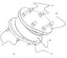
- FIG. 1Bis an isometric view of the cervical artificial disc of FIG. 1A .
- FIG. 1Cis an exploded view of the cervical artificial disc of FIG. 1A .
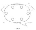
- FIG. 1Dis a superior (or inferior) view of the cervical artificial disc of FIG. 1A .
- FIG. 2Ais a side view of an exemplary cervical artificial disc mobile core.
- FIG. 2Bis an isometric view of the exemplary cervical artificial disc mobile core.
- FIG. 2Cis a front (or back) view of the exemplary cervical artificial disc mobile core.
- FIG. 3Ais a side view of an exemplary cervical artificial disc superior or inferior plate.
- FIG. 3Bis a top oblique-trough side view of the exemplary cervical artificial disc superior or inferior plate.
- FIG. 3Cis a top oblique-spike view of the exemplary cervical artificial disc superior or inferior plate.
- FIG. 3Dis a front-trough side view of the exemplary cervical artificial disc superior or inferior plate.
- FIG. 3Eis a front-spike side view of the exemplary cervical artificial disc superior or inferior plate.
- FIG. 4Ais a cross-sectional view of a cervical disc core showing the angular movements about the x-axis of the cervical disc core with respect to the upper and lower cervical plates (lateral bending).
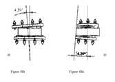
- FIG. 4 Biis a front view of later cervical disc bending.
- FIG. 4 Biiis a side view of flexion/extension cervical artificial disc motion.
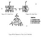
- FIG. 4 Ciis a front view of the artificial disc showing the rotations of the mobile core between the two cervical disc plates about the x-axis (lateral bending or roll).
- FIG. 4 Ciiis a side view of the artificial disc showing the y-axis (flexion/extension or pitch).
- FIG. 4 Ciiiis a perspective view of the artificial disc showing the z-axis (rotation or yaw).
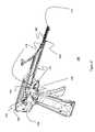
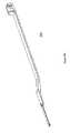
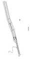
- FIG. 5Ais a front view of a cervical disc plate insertion gun.
- FIG. 5Bis a top view of the cervical disc plate insertion gun.
- FIG. 5Cis a bottom view of the cervical disc plate insertion gun.
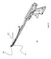
- FIG. 6Ais a perspective, left-side, cut-away view of the cervical disc plate insertion gun.
- FIG. 6Bis a left side, bottom angle view of the cervical disc plate insertion gun.
- FIG. 6Cis a right side, top angle view of the cervical disc plate insertion gun.
- FIG. 6Dis a right side, bottom angle view of the cervical disc plate insertion gun.
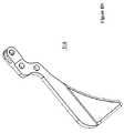
- FIG. 6Eis a cut-away view of the tool tip lower cervical disc replacement plate release mechanism.
- FIG. 7Ais a view of an outside left enclosure of the cervical disc plate insertion gun.
- FIG. 7Bis a view of an inside left enclosure of the cervical disc plate insertion gun.
- FIG. 7Cis a view of an outside right enclosure of the cervical disc plate insertion gun.
- FIG. 7Dis a view of an inside right enclosure of the cervical disc plate insertion gun.
- FIG. 8Ais a top view of inner components of the cervical plate insertion gun including the lower insertion handle.
- FIG. 8Bis a lower insertion handle bottom view.
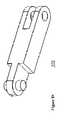
- FIG. 8Cis top view of a lower insertion link.
- FIG. 8Dis bottom view of the lower insertion link.
- FIG. 8Eis a view of the wedge link.
- FIG. 8Fis a top view of the upper insertion handle.
- FIG. 8Gis a lower view of the upper insertion handle lower view.
- FIG. 8His a close-up bottom view of a rear portion of the upper insertion handle.
- FIG. 8Iis a close-up, top view of a forward portion of the upper insertion handle.
- FIG. 8Jis a top view from left of the upper insertion release link.
- FIG. 8Kis a top view from a right side of the upper insertion link.
- FIG. 8Lis a view of a manual upper disc replacement plate driver.
- FIG. 8Mis a view of a trigger spring.
- FIG. 8Nis a view of a trigger.
- FIG. 8Ois a view of a wedge.
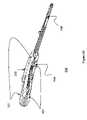
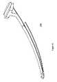
- FIG. 9Ais a perspective cut away view of an exemplary lumbar disc plat insertion gun.
- FIG. 9Bis a cut-away view of the tool tip of the lower lumbar disc replacement plate release mechanism.
- FIGS. 1-9The Medical Device of FIGS. 1-9 .
- the disc device 10includes an upper cervical plate 100 and lower cervical plate 110 , one of which is inserted first by a plate insertion gun 500 .
- the opposite (second) cervical disc plate 110is then inserted with the plate insertion gun 500 maintaining parallel opposition, with opposite plates 100 , 110 and troughs 102 , 112 perfectly aligned.
- a mobile core 150is then inserted and sandwiched in-between both cervical plates 100 , 110 .
- FIGS. 1A-Dillustrate different views of the cervical artificial disc 10 .
- the disc 10includes an upper plate 100 and a lower plate 110 .
- Each platehas a plurality of spikes 101 , 111 , e.g., six spikes 101 , 111 on each plate in a preferred embodiment, on an outer surface of the respective plate, and a centralized trough 102 , 112 on an inner surface of each plate 100 , 110 .
- FIGS. 2A-Cillustrate different views of the cervical mobile core 150 .
- the core 150has a centralized base rim 151 with a superior convexity 152 which interacts with the trough 102 of the upper plate 100 , and an inferior convexity 153 which interacts with the trough 112 of the lower plate 110 .
- FIGS. 3A-Eillustrate different views of the cervical plate (superior or inferior) 100 ( 110 ).
- the plate 100includes a base 114 .
- a trough 112On an upper surface of the inferior plate 110 is a trough 112 .
- a trough 112On an upper surface of the inferior plate 110 is a trough 112 .
- a lower surface of the inferior plate 110On a lower surface of the inferior plate 110 are 6 peripherally arranged spikes 111 . The position of the trough 112 and spikes 111 are reversed for the superior plate ( 100 ).
- a groove 113is defined by the trough 112 ( 102 ) and base 114 ( 104 ) of each plate 110 ( 100 ).
- FIG. 4Aillustrates a cross-sectional view of the cervical artificial disc 10 and the degrees of motion of the mobile core 150 movement about the x-axis with respect to the upper plate 100 and lower plate 110 .
- Each disc plate 100can bend about the x axis by 4.39 degrees clockwise and counter-clockwise (lateral bending). This means that a disc plate 100 , 110 can move ⁇ or +8.78 degrees with respect to the opposite plate 110 , 100 .
- FIG. 4Billustrates a front view of lateral bending of the artificial disc 10 (FIG. 4 Bi), and a side view illustrating flexion-extension of the cervical disc 10 about the y axis which is 4.39 degrees in either flexion or extension.
- FIG. 4Cillustrates the rotation of the mobile core 150 between two cervical plates 100 , 110 about the x (FIG. 4 Ci), y (FIG. 4 Cii) and z (FIG. 4 Ciii) axes.
- Rotation about the x-axisis referred to as roll (alpha) which is lateral bending.
- Rotation about the y axisis referred to as pitch (Beta) which is flexion/extension.
- Rotation about the z axisis referred to as yaw (gamma) which is axial rotation.
- These figuresdisplay different views that show a reference frame for the disc assembly 10 with an origin O at the center of the core 150 .
- the axes of rotationpass through the spherical face of the core 150 which is lower than O but are parallel to both the x and y axes.
- the rotation of the disc plates 100 , 110 about the z-axisis constrained only by the spine motions once the disc 10 is implanted.
- FIGS. 5-8illustrate the components of the cervical disc plate insertion gun 500 .
- the handle 512 of the opening mechanismis made up of left and right enclosures 501 , 502 ( FIGS. 5 , 6 , and 7 ).
- FIG. 7illustrates the inside and outside aspects of left and right enclosures 501 , 502 .
- These enclosures 501 , 502are held together by five enclosure fastening screws 590 ( FIG. 6B ).
- the handle 512holds the mechanism used to insert the upper disc plate 100 and lower disc plate 110 ( FIGS. 5-6 , and FIG. 8 ) into the vertebrae.
- the mechanismhas two functions, including: 1) Holding onto the disc plates 100 , 110 until the user releases them, and 2) opening the tip 560 and forcing one disc plate at a time into a vertebra.
- the mechanismhas two tips 565 , 580 each holding a disc plate 100 , 110 .
- the lower tip 580is composed of two parts: the lower insertion release link 576 and the lower insertion release handle 551 ( FIGS. 6 and 8 ).
- the upper tip 565includes two parts: the upper insertion handle 550 and the upper insertion link 575 ( FIGS. 6 and 8 ).
- Each tip 565 , 580works like a “lobster claw” that holds a disc plate by the “groove” 552 on its cylindrical extrusion.
- the tip 565 , 580is closed the two opposing parts e.g. the lower insertion release link 576 and the lower insertion release handle 551 ( FIGS. 6 and 8 ) hold a disc plate 110 firmly.
- a tip 580opens to release a disc plate as follows.
- a lower tension cable 571pulls on the lower insertion release link 576 ( FIGS. 6 and 8 ) that pivots about the lower release pin 598 ( FIG. 6 ) and opens up a gap big enough to loosen the grip on the disc groove 552 .
- the lower tension cable 571( FIG. 6 ) can only exert a tensile force to open the lobster claw 580 .
- the natural state of the lobster claw 580is to be closed. This is ensured by pre-loading the lower insertion release link 576 with the help of a leaf spring 599 cut into the lower insertion release handle 551 ( FIGS. 6E and 8 ).
- the lower tension cable 571pulls on the lower insertion release link 576 ( FIGS.
- the upper tip 565works in a similar fashion except that its opening is triggered by the upper release button 530 .
- trigger 510rotates, it pushes on the wedge link 513 which in turn pushes on the wedge part 525 ( FIG. 8 ).
- the wedge part 525is wedged at its front action end that creates a gap in between the lower tool tip 580 and upper tool tip 565 forcing them to open.
- a typical disc insertion operationstarts with a lower disc plate 110 placed in the lower tip 580 and the opposing upper disc plate 100 placed on the upper side but away from the tip 565 (as shown in FIGS. 5 , 6 , and 8 ).
- a channel 553 along the upper tip 565 that is formed by the upper insertion release handle 550 and the upper insertion release link 575which holds the second disc plate 100 in place and serves to guide it to the tip 565 when needed.
- the first disc plate 100is inserted into the lower vertebra by opening the tool tip 560 .
- the lower tool tip 585“lower lobster claw”, is kept closed ( FIG. 6 ), securing the disc plate just inserted.
- the tool 500should be left in place.
- the second, upper, disc 100 initially placed in the upper tool half, away from the “upper lobster claw” 565 but away from the tipis then slid down to the end of the upper lobster claw 565 by a flexible and manually activated upper disc replacement plate driver 520 ( FIGS. 6 and 8 ). Once the second disc 100 is positioned at the tip of the upper “lobster claw” 565 ( FIG.
- the tool tip 560is opened once more, i.e., the upper tip 565 and lower lobster claw tip 580 are separated from each other, by virtue of the wedge 525 that is activated by the trigger 510 , via wedge link 513 action.
- the usercan press on the upper release button 530 and lower release button 540 to release both discs (by opening the upper and lower “lobster claws” 565 , 580 ) and at the same time close the tool tip 560 (by releasing the trigger 510 ).
- the tool tip 560then closes while both “lobster claws” 565 , 580 remain open, leaving both disc plates 100 , 110 in place.
- the tool tip 560can then be removed from the patient and a mobile core placed in between the two aligned disc plates 100 , 110 .
- FIG. 9Aillustrates the modified posterior lumbar disc plate insertion gun 700 .
- the gun 700is identical to the cervical disc plate insertion gun 500 except its tips 660 are angled to allow insertion of the specifically sized lumbar disc plates 100 , 110 in the posterior lumbar spine underneath the thecal sac.
- FIG. 9Billustrates an enlarged cut-away view of the tool tip 660 of the lumbar lower disc replacement plate release mechanism 670 .
- the mechanism 670is identical to that described for the cervical mechanism which is illustrated FIG. 6E .
- the tips 660 of the lumbar toolare however, specifically designed and adapted for the typically bean shaped lumbar disc plates.
- the method of insertion of the cervical artificial disc (or lumbar artificial disc) into the anterior cervical spinecan be performed open microscopically, or closed tubularly, using endoscopic and/or fluoroscopic guidance.
- the patientAfter the adequate induction of anesthesia the patient is positioned in the supine position. Routine exposure of the anterior cervical spine is performed and the appropriate disc space is radiographically identified and exposed. A routine complete anterior cervical discectomy is performed.
- the cervical disc platesare inserted onto the cervical disc plate insertion gun 500 .
- the tips 560 of the gun 500are placed into the intervertebral space. Fluoroscopy is used to assure centrality of disc plate placement.
- the trigger 510 of the gun 500is depressed and the bottom plate 110 is inserted into the lower vertebrae. Once this penetrates the bone, the lower plate releasing button 540 is depressed, thereby releasing the plate from the inserter claws 580 ( FIG. 6E ).
- the second upper plate 100is now manually driven into the space by the gun's manual plate driver 520 . Because of the design of the gun 500 , the upper plate 100 is perfectly aligned with the lower plate 110 .
- the gun trigger 510is depressed and this drives the upper plate 100 into the upper vertebrae.
- the upper plate releasing button 530is now depressed, releasing the upper plate 100 from the inserter lobster claws 565 .
- the gun 500is removed from the interspace.
- a mobile core 150 of the appropriate heightis selected and placed in between the upper and lower cervical disc plates 100 , 110 , respectively. The patient is closed routinely.
- the surgical method for the posterior insertion of the PPLTAD into the posterior lumbar interspacecan be performed open microscopically, or closed tubularly, using endoscopic and or fluoroscopic guidance.
- the patientis positioned in the prone position.
- a midline incisionis made, the appropriate unilateral lamina is radiographically identified and exposed, and a unilateral hemi-laminotomy is performed preserving facet stability.
- a complete discectomyis performed, and the superior and inferior endplates are exposed.
- the lumbar plate insertion gun 700is placed underneath the thecal sac. Fluoroscopic guidance may be used to verify centrality of lumbar disc plate placement.
- the trigger of the gun 700is depressed which leads to insertion of the lower lumbar disc plate 100 into the lower vertebra.
- the lower lumbar disc plate releasing buttonis depressed which releases the plate from the inserter claws 551 ( FIG. 9B ).
- the second upper plate 100is now manually driven into the interspace by the gun's 700 manual plate driver ( 520 ). Because of the design of the gun mechanism as described above, the second plate 100 is now perfectly aligned with the first lumbar disc plate 110 .
- the gun triggeris depressed, and this drives the upper plate 100 into the upper vertebrae.
- the upper lumbar disc plate release buttonis now depressed and this releases the upper lumbar disc plate from the claws of the inserter gun 700 .
- the gun 700is removed from the space.
- An appropriately sized mobile core 150is now inserted in between upper and lower lumbar disc plates 100 , 110 . The patient is closed routinely.
- the current deviceallows safe placement of lumbar and cervical artificial discs into the spine without intervertebral distraction, and therefore places minimal tension on facet joints.
- the method of insertionis quick, gentle, and time efficient.
- the plate insertion guncould potentially be adapted for other inter-joint orthopedic devices, and further adaptations may have applications in manufacturing, toy, carpentry and other industries.
Landscapes
- Health & Medical Sciences (AREA)
- Engineering & Computer Science (AREA)
- Biomedical Technology (AREA)
- Orthopedic Medicine & Surgery (AREA)
- Neurology (AREA)
- Transplantation (AREA)
- Heart & Thoracic Surgery (AREA)
- Oral & Maxillofacial Surgery (AREA)
- Cardiology (AREA)
- Vascular Medicine (AREA)
- Life Sciences & Earth Sciences (AREA)
- Animal Behavior & Ethology (AREA)
- General Health & Medical Sciences (AREA)
- Public Health (AREA)
- Veterinary Medicine (AREA)
- Physical Education & Sports Medicine (AREA)
- Prostheses (AREA)
Abstract
Description
Claims (44)
Priority Applications (9)
| Application Number | Priority Date | Filing Date | Title |
|---|---|---|---|
| US11/943,334US8535379B2 (en) | 2006-04-04 | 2007-11-20 | Artificial cervical and lumbar discs, disc plate insertion gun for performing sequential single plate intervertebral implantation enabling symmetric bi-disc plate alignment for interplate mobile core placement |
| US13/893,326US9056018B2 (en) | 2004-05-13 | 2013-05-13 | Artificial cervical and lumbar discs, disc plate insertion gun for performing sequential single plate intervertebral implantation enabling symmetric bi-disc plate alignment for interplate mobile core placement |
| US14/739,327US9867712B2 (en) | 2004-05-13 | 2015-06-15 | Artificial cervical and lumbar discs, disc plate insertion gun for performing sequential single plate intervertebral implantation enabling symmetric bi-disc plate alignment for interplate mobile core placement |
| US15/870,406US10610371B2 (en) | 2004-05-13 | 2018-01-12 | Artificial cervical and lumbar discs, disc plate insertion gun for performing sequential single plate intervertebral implantation enabling symmetric bi-disc plate alignment for interplate mobile core placement |
| US15/944,221US10376376B2 (en) | 2004-05-13 | 2018-04-03 | Artificial cervical and lumbar discs, disc plate insertion gun for performing sequential single plate intervertebral implantation enabling symmetric bi-disc plate alignment for interplate mobile core placement |
| US16/018,798US10369003B2 (en) | 2004-05-13 | 2018-06-26 | Artificial cervical and lumbar discs, disc plate insertion gun for performing sequential single plate intervertebral implantation enabling symmetric bi-disc plate alignment for interplate mobile core placement |
| US16/841,355US11478359B2 (en) | 2004-05-13 | 2020-04-06 | Artificial disc system |
| US17/129,149US11083591B2 (en) | 2004-05-13 | 2020-12-21 | Artificial cervical and lumbar disc system |
| US17/393,672US11806244B2 (en) | 2004-05-13 | 2021-08-04 | Artificial cervical and lumbar disc system |
Applications Claiming Priority (2)
| Application Number | Priority Date | Filing Date | Title |
|---|---|---|---|
| US78872006P | 2006-04-04 | 2006-04-04 | |
| US11/943,334US8535379B2 (en) | 2006-04-04 | 2007-11-20 | Artificial cervical and lumbar discs, disc plate insertion gun for performing sequential single plate intervertebral implantation enabling symmetric bi-disc plate alignment for interplate mobile core placement |
Related Parent Applications (2)
| Application Number | Title | Priority Date | Filing Date |
|---|---|---|---|
| US10/964,633ContinuationUS20050256576A1 (en) | 2004-05-12 | 2004-10-15 | Artificial expansile total lumbar and thoracic discs for posterior placement without supplemental instrumentation and its adaptation for anterior placement of artificial cervical, thoracic and lumbar discs |
| US11/487,415Continuation-In-PartUS7854766B2 (en) | 2004-05-13 | 2006-07-17 | Artificial total lumbar disc for unilateral safe and simple posterior placement in the lumbar spine, and removable bifunctional screw which drives vertical sliding expansile plate expansion, and interplate widening, and angled traction spikes |
Related Child Applications (1)
| Application Number | Title | Priority Date | Filing Date |
|---|---|---|---|
| US13/893,326ContinuationUS9056018B2 (en) | 2004-05-13 | 2013-05-13 | Artificial cervical and lumbar discs, disc plate insertion gun for performing sequential single plate intervertebral implantation enabling symmetric bi-disc plate alignment for interplate mobile core placement |
Publications (2)
| Publication Number | Publication Date |
|---|---|
| US20090132051A1 US20090132051A1 (en) | 2009-05-21 |
| US8535379B2true US8535379B2 (en) | 2013-09-17 |
Family
ID=40642802
Family Applications (8)
| Application Number | Title | Priority Date | Filing Date |
|---|---|---|---|
| US11/943,334Active2026-12-13US8535379B2 (en) | 2004-05-13 | 2007-11-20 | Artificial cervical and lumbar discs, disc plate insertion gun for performing sequential single plate intervertebral implantation enabling symmetric bi-disc plate alignment for interplate mobile core placement |
| US13/893,326Expired - LifetimeUS9056018B2 (en) | 2004-05-13 | 2013-05-13 | Artificial cervical and lumbar discs, disc plate insertion gun for performing sequential single plate intervertebral implantation enabling symmetric bi-disc plate alignment for interplate mobile core placement |
| US14/739,327Expired - Fee RelatedUS9867712B2 (en) | 2004-05-13 | 2015-06-15 | Artificial cervical and lumbar discs, disc plate insertion gun for performing sequential single plate intervertebral implantation enabling symmetric bi-disc plate alignment for interplate mobile core placement |
| US15/870,406Expired - LifetimeUS10610371B2 (en) | 2004-05-13 | 2018-01-12 | Artificial cervical and lumbar discs, disc plate insertion gun for performing sequential single plate intervertebral implantation enabling symmetric bi-disc plate alignment for interplate mobile core placement |
| US15/944,221Expired - LifetimeUS10376376B2 (en) | 2004-05-13 | 2018-04-03 | Artificial cervical and lumbar discs, disc plate insertion gun for performing sequential single plate intervertebral implantation enabling symmetric bi-disc plate alignment for interplate mobile core placement |
| US16/018,798Expired - Fee RelatedUS10369003B2 (en) | 2004-05-13 | 2018-06-26 | Artificial cervical and lumbar discs, disc plate insertion gun for performing sequential single plate intervertebral implantation enabling symmetric bi-disc plate alignment for interplate mobile core placement |
| US16/841,355Expired - LifetimeUS11478359B2 (en) | 2004-05-13 | 2020-04-06 | Artificial disc system |
| US17/129,149Expired - Fee RelatedUS11083591B2 (en) | 2004-05-13 | 2020-12-21 | Artificial cervical and lumbar disc system |
Family Applications After (7)
| Application Number | Title | Priority Date | Filing Date |
|---|---|---|---|
| US13/893,326Expired - LifetimeUS9056018B2 (en) | 2004-05-13 | 2013-05-13 | Artificial cervical and lumbar discs, disc plate insertion gun for performing sequential single plate intervertebral implantation enabling symmetric bi-disc plate alignment for interplate mobile core placement |
| US14/739,327Expired - Fee RelatedUS9867712B2 (en) | 2004-05-13 | 2015-06-15 | Artificial cervical and lumbar discs, disc plate insertion gun for performing sequential single plate intervertebral implantation enabling symmetric bi-disc plate alignment for interplate mobile core placement |
| US15/870,406Expired - LifetimeUS10610371B2 (en) | 2004-05-13 | 2018-01-12 | Artificial cervical and lumbar discs, disc plate insertion gun for performing sequential single plate intervertebral implantation enabling symmetric bi-disc plate alignment for interplate mobile core placement |
| US15/944,221Expired - LifetimeUS10376376B2 (en) | 2004-05-13 | 2018-04-03 | Artificial cervical and lumbar discs, disc plate insertion gun for performing sequential single plate intervertebral implantation enabling symmetric bi-disc plate alignment for interplate mobile core placement |
| US16/018,798Expired - Fee RelatedUS10369003B2 (en) | 2004-05-13 | 2018-06-26 | Artificial cervical and lumbar discs, disc plate insertion gun for performing sequential single plate intervertebral implantation enabling symmetric bi-disc plate alignment for interplate mobile core placement |
| US16/841,355Expired - LifetimeUS11478359B2 (en) | 2004-05-13 | 2020-04-06 | Artificial disc system |
| US17/129,149Expired - Fee RelatedUS11083591B2 (en) | 2004-05-13 | 2020-12-21 | Artificial cervical and lumbar disc system |
Country Status (1)
| Country | Link |
|---|---|
| US (8) | US8535379B2 (en) |
Cited By (7)
| Publication number | Priority date | Publication date | Assignee | Title |
|---|---|---|---|---|
| US20100292799A1 (en)* | 2009-05-15 | 2010-11-18 | Noah Hansell | Method for Inserting and Positioning an Artificial Disc |
| US20160220285A1 (en)* | 2013-07-01 | 2016-08-04 | Biospine Implants | Dynamic intervertebral stabilisation device |
| US11083591B2 (en) | 2004-05-13 | 2021-08-10 | Moskowitz Family Llc | Artificial cervical and lumbar disc system |
| US11116642B2 (en) | 2009-11-25 | 2021-09-14 | Moskowitz Family Llc | Total artificial spino-laminar prosthetic replacement |
| US11452618B2 (en) | 2019-09-23 | 2022-09-27 | Dimicron, Inc | Spinal artificial disc removal tool |
| US11839554B2 (en) | 2020-01-23 | 2023-12-12 | Robert S. Bray, Jr. | Method of implanting an artificial disc replacement device |
| US11938035B2 (en) | 2019-12-04 | 2024-03-26 | Robert S. Bray, Jr. | Artificial disc replacement device |
Families Citing this family (20)
| Publication number | Priority date | Publication date | Assignee | Title |
|---|---|---|---|---|
| AR038680A1 (en) | 2002-02-19 | 2005-01-26 | Synthes Ag | INTERVERTEBRAL IMPLANT |
| CA2515247C (en) | 2003-02-06 | 2010-10-05 | Synthes (U.S.A.) | Intervertebral implant |
| EP1988855A2 (en) | 2006-02-27 | 2008-11-12 | Synthes GmbH | Intervertebral implant with fixation geometry |
| JP2011502708A (en) | 2007-11-16 | 2011-01-27 | ジンテス ゲゼルシャフト ミット ベシュレンクテル ハフツング | Low profile intervertebral implant |
| US9700431B2 (en)* | 2008-08-13 | 2017-07-11 | Smed-Ta/Td, Llc | Orthopaedic implant with porous structural member |
| US9616205B2 (en) | 2008-08-13 | 2017-04-11 | Smed-Ta/Td, Llc | Drug delivery implants |
| US10842645B2 (en) | 2008-08-13 | 2020-11-24 | Smed-Ta/Td, Llc | Orthopaedic implant with porous structural member |
| US20100042213A1 (en) | 2008-08-13 | 2010-02-18 | Nebosky Paul S | Drug delivery implants |
| JP2012500058A (en)* | 2008-08-13 | 2012-01-05 | スメド−ティーエイ/ティーディー・エルエルシー | Orthopedic implant with a porous structural member |
| WO2010025386A1 (en) | 2008-08-29 | 2010-03-04 | Smed-Ta/Td, Llc | Orthopaedic implant |
| CN102256570B (en) | 2008-11-07 | 2015-09-02 | 斯恩蒂斯有限公司 | Spacer and connecting plate assembly between vertebral bodies |
| US8858636B2 (en)* | 2010-04-09 | 2014-10-14 | DePuy Synthes Products, LLC | Intervertebral implant |
| US8496713B2 (en)* | 2010-12-10 | 2013-07-30 | Globus Medical, Inc. | Spine stabilization device and methods |
| WO2012088238A2 (en) | 2010-12-21 | 2012-06-28 | Synthes Usa, Llc | Intervertebral implants, systems, and methods of use |
| US9084683B2 (en) | 2011-01-07 | 2015-07-21 | Pbn Spinal Implants, Llc | Spinal implant system and method |
| US9867718B2 (en) | 2014-10-22 | 2018-01-16 | DePuy Synthes Products, Inc. | Intervertebral implants, systems, and methods of use |
| US10504827B2 (en)* | 2016-06-03 | 2019-12-10 | Amkor Technology, Inc. | Semiconductor device and manufacturing method thereof |
| US10905566B2 (en)* | 2018-02-05 | 2021-02-02 | Spineology Inc. | Percutaneous posterior implant slide |
| CN112353529B (en)* | 2020-11-11 | 2021-06-04 | 吉林大学 | A biomimetic flexible intervertebral disc that effectively maintains intervertebral height |
| WO2025018962A1 (en)* | 2023-07-14 | 2025-01-23 | Celal Bayar Universitesi Diger Merkezler Mudurlugu | An artificial disc prosthesis capable of mimicking movement in all axes |
Citations (41)
| Publication number | Priority date | Publication date | Assignee | Title |
|---|---|---|---|---|
| US4554914A (en) | 1983-10-04 | 1985-11-26 | Kapp John P | Prosthetic vertebral body |
| US4636217A (en) | 1985-04-23 | 1987-01-13 | Regents Of The University Of Minnesota | Anterior spinal implant |
| US4759766A (en)* | 1984-09-04 | 1988-07-26 | Humboldt-Universitaet Zu Berlin | Intervertebral disc endoprosthesis |
| US4960420A (en) | 1988-08-23 | 1990-10-02 | Marlowe Goble E | Channel ligament clamp and system |
| US4997432A (en) | 1988-03-23 | 1991-03-05 | Waldemar Link Gmbh & Co. | Surgical instrument set |
| US5123926A (en) | 1991-02-22 | 1992-06-23 | Madhavan Pisharodi | Artificial spinal prosthesis |
| US5401269A (en)* | 1992-03-13 | 1995-03-28 | Waldemar Link Gmbh & Co. | Intervertebral disc endoprosthesis |
| US5514180A (en) | 1994-01-14 | 1996-05-07 | Heggeness; Michael H. | Prosthetic intervertebral devices |
| US5660188A (en) | 1991-05-09 | 1997-08-26 | Groiso; Jorge A. | Procedure for applying an elastic clip |
| US5667472A (en) | 1994-03-18 | 1997-09-16 | Clarus Medical Systems, Inc. | Surgical instrument and method for use with a viewing system |
| US5782832A (en) | 1996-10-01 | 1998-07-21 | Surgical Dynamics, Inc. | Spinal fusion implant and method of insertion thereof |
| US5960522A (en) | 1997-05-21 | 1999-10-05 | Micron Electronics, Inc. | Ribbon cable alligator clamp |
| US6126689A (en) | 1998-06-15 | 2000-10-03 | Expanding Concepts, L.L.C. | Collapsible and expandable interbody fusion device |
| US6368350B1 (en) | 1999-03-11 | 2002-04-09 | Sulzer Spine-Tech Inc. | Intervertebral disc prosthesis and method |
| US6375682B1 (en) | 2001-08-06 | 2002-04-23 | Lewis W. Fleischmann | Collapsible, rotatable and expandable spinal hydraulic prosthetic device |
| US6419704B1 (en) | 1999-10-08 | 2002-07-16 | Bret Ferree | Artificial intervertebral disc replacement methods and apparatus |
| US6458159B1 (en) | 2000-08-15 | 2002-10-01 | John S. Thalgott | Disc prosthesis |
| US6527804B1 (en) | 1998-12-11 | 2003-03-04 | Dimso (Distribution Medicale Du Sud-Quest) | Intervertebral disk prosthesis |
| US6533818B1 (en) | 2000-04-26 | 2003-03-18 | Pearl Technology Holdings, Llc | Artificial spinal disc |
| US6572653B1 (en) | 2001-12-07 | 2003-06-03 | Rush E. Simonson | Vertebral implant adapted for posterior insertion |
| US6579318B2 (en) | 2000-06-12 | 2003-06-17 | Ortho Development Corporation | Intervertebral spacer |
| US6582468B1 (en) | 1998-12-11 | 2003-06-24 | Spryker Spine | Intervertebral disc prosthesis with compressible body |
| US6641614B1 (en) | 1997-05-01 | 2003-11-04 | Spinal Concepts, Inc. | Multi-variable-height fusion device |
| US6719794B2 (en) | 2001-05-03 | 2004-04-13 | Synthes (U.S.A.) | Intervertebral implant for transforaminal posterior lumbar interbody fusion procedure |
| US6723126B1 (en) | 2002-11-01 | 2004-04-20 | Sdgi Holdings, Inc. | Laterally expandable cage |
| US6733532B1 (en) | 1998-12-11 | 2004-05-11 | Stryker Spine | Intervertebral disc prosthesis with improved mechanical behavior |
| US6764491B2 (en) | 1999-10-21 | 2004-07-20 | Sdgi Holdings, Inc. | Devices and techniques for a posterior lateral disc space approach |
| US6770094B2 (en) | 2001-07-05 | 2004-08-03 | Gerald Fehling | Intervertebral disc prosthesis |
| US20040177531A1 (en) | 2003-03-10 | 2004-09-16 | Adidas International Marketing B.V. | Intelligent footwear systems |
| US20040254644A1 (en) | 2002-10-21 | 2004-12-16 | Taylor Brett Allison | Intervertebral disk prosthesis |
| US20050027362A1 (en) | 1999-02-26 | 2005-02-03 | Williams Lytton A. | Method and apparatus for intervertebral implant anchorage |
| US20050049590A1 (en) | 2003-03-07 | 2005-03-03 | Neville Alleyne | Spinal implant with securement spikes |
| US6904308B2 (en) | 2001-05-20 | 2005-06-07 | Given Imaging Ltd. | Array system and method for locating an in vivo signal source |
| US20050216084A1 (en) | 2003-04-22 | 2005-09-29 | Fleischmann Lewis W | Collapsible, rotatable, and tiltable hydraulic spinal disc prosthesis system with selectable modular components |
| US6955671B2 (en) | 1999-02-18 | 2005-10-18 | Olympus Corporation | Remote surgery support system |
| US20050273170A1 (en) | 2004-06-08 | 2005-12-08 | Navarro Richard R | Prosthetic intervertebral spinal disc with integral microprocessor |
| US20050278026A1 (en) | 2003-08-05 | 2005-12-15 | Gordon Charles R | Expandable intervertebral implant with wedged expansion member |
| US7030904B2 (en) | 1997-10-06 | 2006-04-18 | Micro-Medical Devices, Inc. | Reduced area imaging device incorporated within wireless endoscopic devices |
| US7037258B2 (en) | 1999-09-24 | 2006-05-02 | Karl Storz Imaging, Inc. | Image orientation for endoscopic video displays |
| US7097615B2 (en) | 2001-10-05 | 2006-08-29 | Boston Scientific Scimed, Inc. | Robotic endoscope with wireless interface |
| US20070198089A1 (en)* | 2004-05-13 | 2007-08-23 | Nathan Moskowitz | Artificial total lumbar disc for unilateral safe and simple posterior placement in the lumbar spine, and removable bifunctional screw which drives vertical sliding expansile plate expansion, and interplate widening,and angled traction spikes |
Family Cites Families (32)
| Publication number | Priority date | Publication date | Assignee | Title |
|---|---|---|---|---|
| US1036900A (en) | 1907-12-16 | 1912-08-27 | Holtzer Cabot Electric Co | Frequency-meter. |
| US1037637A (en) | 1911-08-02 | 1912-09-03 | William H Kienker | Electrically-operable open-at-will elevator-gate mechanism. |
| US1061037A (en) | 1913-02-20 | 1913-05-06 | J B Symes | Compound rail. |
| FR2659226B1 (en) | 1990-03-07 | 1992-05-29 | Jbs Sa | PROSTHESIS FOR INTERVERTEBRAL DISCS AND ITS IMPLEMENTATION INSTRUMENTS. |
| US5674296A (en) | 1994-11-14 | 1997-10-07 | Spinal Dynamics Corporation | Human spinal disc prosthesis |
| US6113637A (en) | 1998-10-22 | 2000-09-05 | Sofamor Danek Holdings, Inc. | Artificial intervertebral joint permitting translational and rotational motion |
| US6193757B1 (en) | 1998-10-29 | 2001-02-27 | Sdgi Holdings, Inc. | Expandable intervertebral spacers |
| US6866682B1 (en) | 1999-09-02 | 2005-03-15 | Stryker Spine | Distractable corpectomy device |
| EP1792586B1 (en) | 1999-09-14 | 2012-12-26 | Spine Solutions Inc. | Insert instrument for an implant between vertebrae |
| US6610093B1 (en) | 2000-07-28 | 2003-08-26 | Perumala Corporation | Method and apparatus for stabilizing adjacent vertebrae |
| TW545211U (en) | 2001-08-29 | 2003-08-01 | Jung-Chiuan Ye | Device for fastening spine |
| US7018415B1 (en) | 2002-09-23 | 2006-03-28 | Sdgi Holdings, Inc. | Expandable spinal fusion device and methods of promoting spinal fusion |
| US6899735B2 (en) | 2002-10-02 | 2005-05-31 | Sdgi Holdings, Inc. | Modular intervertebral prosthesis system |
| FR2846550B1 (en) | 2002-11-05 | 2006-01-13 | Ldr Medical | INTERVERTEBRAL DISC PROSTHESIS |
| US6908484B2 (en) | 2003-03-06 | 2005-06-21 | Spinecore, Inc. | Cervical disc replacement |
| US6981989B1 (en) | 2003-04-22 | 2006-01-03 | X-Pantu-Flex Drd Limited Liability Company | Rotatable and reversibly expandable spinal hydraulic prosthetic device |
| US7442211B2 (en) | 2003-05-27 | 2008-10-28 | Spinalmotion, Inc. | Intervertebral prosthetic disc |
| US7811329B2 (en) | 2003-07-31 | 2010-10-12 | Globus Medical | Transforaminal prosthetic spinal disc replacement and methods thereof |
| US7621956B2 (en) | 2003-07-31 | 2009-11-24 | Globus Medical, Inc. | Prosthetic spinal disc replacement |
| US7204853B2 (en) | 2003-08-05 | 2007-04-17 | Flexuspine, Inc. | Artificial functional spinal unit assemblies |
| US7819922B2 (en) | 2003-10-16 | 2010-10-26 | Spinal Generations, Llc | Vertebral prosthesis |
| US7217293B2 (en) | 2003-11-21 | 2007-05-15 | Warsaw Orthopedic, Inc. | Expandable spinal implant |
| JP2005191508A (en) | 2003-12-05 | 2005-07-14 | Rohm Co Ltd | Semiconductor device and manufacturing method thereof |
| US7137997B2 (en) | 2003-12-29 | 2006-11-21 | Globus Medical, Inc. | Spinal fusion implant |
| US7250060B2 (en) | 2004-01-27 | 2007-07-31 | Sdgi Holdings, Inc. | Hybrid intervertebral disc system |
| US7115144B2 (en) | 2004-03-02 | 2006-10-03 | Joint Synergy, Llc | Spinal implant |
| US8535379B2 (en) | 2006-04-04 | 2013-09-17 | Nathan C. Moskowitz | Artificial cervical and lumbar discs, disc plate insertion gun for performing sequential single plate intervertebral implantation enabling symmetric bi-disc plate alignment for interplate mobile core placement |
| US8911498B2 (en) | 2005-02-10 | 2014-12-16 | DePuy Synthes Products, LLC | Intervertebral prosthetic disc |
| US7985256B2 (en) | 2005-09-26 | 2011-07-26 | Coalign Innovations, Inc. | Selectively expanding spine cage, hydraulically controllable in three dimensions for enhanced spinal fusion |
| US8070813B2 (en) | 2005-09-26 | 2011-12-06 | Coalign Innovations, Inc. | Selectively expanding spine cage, hydraulically controllable in three dimensions for vertebral body replacement |
| US7927373B2 (en)* | 2005-10-31 | 2011-04-19 | Depuy Spine, Inc. | Intervertebral disc prosthesis |
| US7867279B2 (en) | 2006-01-23 | 2011-01-11 | Depuy Spine, Inc. | Intervertebral disc prosthesis |
- 2007
- 2007-11-20USUS11/943,334patent/US8535379B2/enactiveActive
- 2013
- 2013-05-13USUS13/893,326patent/US9056018B2/ennot_activeExpired - Lifetime
- 2015
- 2015-06-15USUS14/739,327patent/US9867712B2/ennot_activeExpired - Fee Related
- 2018
- 2018-01-12USUS15/870,406patent/US10610371B2/ennot_activeExpired - Lifetime
- 2018-04-03USUS15/944,221patent/US10376376B2/ennot_activeExpired - Lifetime
- 2018-06-26USUS16/018,798patent/US10369003B2/ennot_activeExpired - Fee Related
- 2020
- 2020-04-06USUS16/841,355patent/US11478359B2/ennot_activeExpired - Lifetime
- 2020-12-21USUS17/129,149patent/US11083591B2/ennot_activeExpired - Fee Related
Patent Citations (42)
| Publication number | Priority date | Publication date | Assignee | Title |
|---|---|---|---|---|
| US4554914A (en) | 1983-10-04 | 1985-11-26 | Kapp John P | Prosthetic vertebral body |
| US4759766A (en)* | 1984-09-04 | 1988-07-26 | Humboldt-Universitaet Zu Berlin | Intervertebral disc endoprosthesis |
| US4636217A (en) | 1985-04-23 | 1987-01-13 | Regents Of The University Of Minnesota | Anterior spinal implant |
| US4997432A (en) | 1988-03-23 | 1991-03-05 | Waldemar Link Gmbh & Co. | Surgical instrument set |
| US4960420A (en) | 1988-08-23 | 1990-10-02 | Marlowe Goble E | Channel ligament clamp and system |
| US5123926A (en) | 1991-02-22 | 1992-06-23 | Madhavan Pisharodi | Artificial spinal prosthesis |
| US5660188A (en) | 1991-05-09 | 1997-08-26 | Groiso; Jorge A. | Procedure for applying an elastic clip |
| US5401269A (en)* | 1992-03-13 | 1995-03-28 | Waldemar Link Gmbh & Co. | Intervertebral disc endoprosthesis |
| US5514180A (en) | 1994-01-14 | 1996-05-07 | Heggeness; Michael H. | Prosthetic intervertebral devices |
| US5667472A (en) | 1994-03-18 | 1997-09-16 | Clarus Medical Systems, Inc. | Surgical instrument and method for use with a viewing system |
| US5782832A (en) | 1996-10-01 | 1998-07-21 | Surgical Dynamics, Inc. | Spinal fusion implant and method of insertion thereof |
| US6641614B1 (en) | 1997-05-01 | 2003-11-04 | Spinal Concepts, Inc. | Multi-variable-height fusion device |
| US5960522A (en) | 1997-05-21 | 1999-10-05 | Micron Electronics, Inc. | Ribbon cable alligator clamp |
| US7030904B2 (en) | 1997-10-06 | 2006-04-18 | Micro-Medical Devices, Inc. | Reduced area imaging device incorporated within wireless endoscopic devices |
| US6126689A (en) | 1998-06-15 | 2000-10-03 | Expanding Concepts, L.L.C. | Collapsible and expandable interbody fusion device |
| US6527804B1 (en) | 1998-12-11 | 2003-03-04 | Dimso (Distribution Medicale Du Sud-Quest) | Intervertebral disk prosthesis |
| US6582468B1 (en) | 1998-12-11 | 2003-06-24 | Spryker Spine | Intervertebral disc prosthesis with compressible body |
| US6733532B1 (en) | 1998-12-11 | 2004-05-11 | Stryker Spine | Intervertebral disc prosthesis with improved mechanical behavior |
| US6955671B2 (en) | 1999-02-18 | 2005-10-18 | Olympus Corporation | Remote surgery support system |
| US20050027362A1 (en) | 1999-02-26 | 2005-02-03 | Williams Lytton A. | Method and apparatus for intervertebral implant anchorage |
| US6368350B1 (en) | 1999-03-11 | 2002-04-09 | Sulzer Spine-Tech Inc. | Intervertebral disc prosthesis and method |
| US7037258B2 (en) | 1999-09-24 | 2006-05-02 | Karl Storz Imaging, Inc. | Image orientation for endoscopic video displays |
| US6419704B1 (en) | 1999-10-08 | 2002-07-16 | Bret Ferree | Artificial intervertebral disc replacement methods and apparatus |
| US6764491B2 (en) | 1999-10-21 | 2004-07-20 | Sdgi Holdings, Inc. | Devices and techniques for a posterior lateral disc space approach |
| US6533818B1 (en) | 2000-04-26 | 2003-03-18 | Pearl Technology Holdings, Llc | Artificial spinal disc |
| US6579318B2 (en) | 2000-06-12 | 2003-06-17 | Ortho Development Corporation | Intervertebral spacer |
| US6458159B1 (en) | 2000-08-15 | 2002-10-01 | John S. Thalgott | Disc prosthesis |
| US6719794B2 (en) | 2001-05-03 | 2004-04-13 | Synthes (U.S.A.) | Intervertebral implant for transforaminal posterior lumbar interbody fusion procedure |
| US6904308B2 (en) | 2001-05-20 | 2005-06-07 | Given Imaging Ltd. | Array system and method for locating an in vivo signal source |
| US6770094B2 (en) | 2001-07-05 | 2004-08-03 | Gerald Fehling | Intervertebral disc prosthesis |
| US6375682B1 (en) | 2001-08-06 | 2002-04-23 | Lewis W. Fleischmann | Collapsible, rotatable and expandable spinal hydraulic prosthetic device |
| US7097615B2 (en) | 2001-10-05 | 2006-08-29 | Boston Scientific Scimed, Inc. | Robotic endoscope with wireless interface |
| US6572653B1 (en) | 2001-12-07 | 2003-06-03 | Rush E. Simonson | Vertebral implant adapted for posterior insertion |
| US20040254644A1 (en) | 2002-10-21 | 2004-12-16 | Taylor Brett Allison | Intervertebral disk prosthesis |
| US20040088054A1 (en) | 2002-11-01 | 2004-05-06 | Bret Berry | Laterally expandable cage |
| US6723126B1 (en) | 2002-11-01 | 2004-04-20 | Sdgi Holdings, Inc. | Laterally expandable cage |
| US20050049590A1 (en) | 2003-03-07 | 2005-03-03 | Neville Alleyne | Spinal implant with securement spikes |
| US20040177531A1 (en) | 2003-03-10 | 2004-09-16 | Adidas International Marketing B.V. | Intelligent footwear systems |
| US20050216084A1 (en) | 2003-04-22 | 2005-09-29 | Fleischmann Lewis W | Collapsible, rotatable, and tiltable hydraulic spinal disc prosthesis system with selectable modular components |
| US20050278026A1 (en) | 2003-08-05 | 2005-12-15 | Gordon Charles R | Expandable intervertebral implant with wedged expansion member |
| US20070198089A1 (en)* | 2004-05-13 | 2007-08-23 | Nathan Moskowitz | Artificial total lumbar disc for unilateral safe and simple posterior placement in the lumbar spine, and removable bifunctional screw which drives vertical sliding expansile plate expansion, and interplate widening,and angled traction spikes |
| US20050273170A1 (en) | 2004-06-08 | 2005-12-08 | Navarro Richard R | Prosthetic intervertebral spinal disc with integral microprocessor |
Non-Patent Citations (5)
| Title |
|---|
| Dieter Grob et al., "Clinical Experience With the Dynesys Semirigid Fixation System for the Lumbar Spine," Spine, vol. 30, No. 3, 2005, pp. 324-331. |
| E.K. Wai et al., "Disk Replacement Arthroplasties: Can the Success of Hip and Knee Replacements be Repeated in the Spine?," Seminars in Spine Surgery, vol. 15, No. 4 Dec. 2003, pp. 473-482. |
| International Search Report (ISR) and Written Opinion of the International Searching Authority, Dec. 3, 2007, International Application No. PCT/US 07/05005. |
| Richard D. Guyer et al., "Intervertebral Disc Prostheses," Spine Journal, vol. 28, No. 15S, Supp. To Aug. 1, 2003, pp. S15-S23. |
| Vincent C. Traynelis, "Prosthetics and Biologics: The Wave of the Future," Clinical Neurosurgery, vol. 50, Proceedings of the Congress of Neurological Surgeons, Philadelphia, PA 2002, Chapter 9, pp. 207-219. |
Cited By (13)
| Publication number | Priority date | Publication date | Assignee | Title |
|---|---|---|---|---|
| US11478359B2 (en) | 2004-05-13 | 2022-10-25 | Moskowitz Family Llc | Artificial disc system |
| US11083591B2 (en) | 2004-05-13 | 2021-08-10 | Moskowitz Family Llc | Artificial cervical and lumbar disc system |
| US9066809B2 (en)* | 2009-05-15 | 2015-06-30 | Globus Medical Inc. | Method for inserting and positioning an artificial disc |
| US20100292799A1 (en)* | 2009-05-15 | 2010-11-18 | Noah Hansell | Method for Inserting and Positioning an Artificial Disc |
| US11116642B2 (en) | 2009-11-25 | 2021-09-14 | Moskowitz Family Llc | Total artificial spino-laminar prosthetic replacement |
| US20160220285A1 (en)* | 2013-07-01 | 2016-08-04 | Biospine Implants | Dynamic intervertebral stabilisation device |
| US10039575B2 (en)* | 2013-07-01 | 2018-08-07 | Cousin Biotech Sas | Dynamic intervertebral stabilisation device |
| US11452618B2 (en) | 2019-09-23 | 2022-09-27 | Dimicron, Inc | Spinal artificial disc removal tool |
| US11590003B2 (en) | 2019-09-23 | 2023-02-28 | Dimicron Inc. | Spinal artificial disc removal tool |
| US11938035B2 (en) | 2019-12-04 | 2024-03-26 | Robert S. Bray, Jr. | Artificial disc replacement device |
| US12329651B2 (en) | 2019-12-04 | 2025-06-17 | TRM IP Management, LLC | Artificial disc replacement device |
| US11839554B2 (en) | 2020-01-23 | 2023-12-12 | Robert S. Bray, Jr. | Method of implanting an artificial disc replacement device |
| US12303406B2 (en) | 2020-01-23 | 2025-05-20 | Trm Ip Management Llc | Method of implanting an artificial disc replacement device |
Also Published As
| Publication number | Publication date |
|---|---|
| US20180368985A1 (en) | 2018-12-27 |
| US20200297504A1 (en) | 2020-09-24 |
| US20090132051A1 (en) | 2009-05-21 |
| US10610371B2 (en) | 2020-04-07 |
| US11083591B2 (en) | 2021-08-10 |
| US10369003B2 (en) | 2019-08-06 |
| US9867712B2 (en) | 2018-01-16 |
| US20140067067A1 (en) | 2014-03-06 |
| US11478359B2 (en) | 2022-10-25 |
| US9056018B2 (en) | 2015-06-16 |
| US20210106431A1 (en) | 2021-04-15 |
| US20180140431A1 (en) | 2018-05-24 |
| US10376376B2 (en) | 2019-08-13 |
| US20180333271A1 (en) | 2018-11-22 |
| US20160100952A1 (en) | 2016-04-14 |
Similar Documents
| Publication | Publication Date | Title |
|---|---|---|
| US11478359B2 (en) | Artificial disc system | |
| JP4047937B2 (en) | Artificial facet joint allowing translation and rotation | |
| JP4701162B2 (en) | Cervical disc replacement | |
| US8562682B2 (en) | Artificial intervertebral joint permitting translational and rotational motion | |
| US6146421A (en) | Multiple axis intervertebral prosthesis | |
| US6228118B1 (en) | Multiple axis intervertebral prosthesis | |
| US20020077702A1 (en) | Dynamic implanted intervertebral spacer | |
| US20070123906A1 (en) | Inserter/impactor for implanting an artificial intervertebral disc | |
| JP2003038534A (en) | Module type fixed gauge, spinal implant system and method of implanting spinal disc prosthesis | |
| US20060287728A1 (en) | System and method for implanting intervertebral disk prostheses | |
| US20080133014A1 (en) | Artificial intervertebral disc assembly and method for assembly within spine | |
| KR20110060916A (en) | Implants with Spiral Anchors | |
| US20070198092A1 (en) | System for inserting artificial intervertebral discs | |
| US20220062002A1 (en) | Artificial cervical and lumbar disc system | |
| JP2007090114A (en) | Artificial intervertebral joint to allow parallel translation and rotating operation |
Legal Events
| Date | Code | Title | Description |
|---|---|---|---|
| FEPP | Fee payment procedure | Free format text:PAYOR NUMBER ASSIGNED (ORIGINAL EVENT CODE: ASPN); ENTITY STATUS OF PATENT OWNER: SMALL ENTITY | |
| STCF | Information on status: patent grant | Free format text:PATENTED CASE | |
| AS | Assignment | Owner name:MOSKOWITZ, NATHAN C., MARYLAND Free format text:ASSIGNMENT OF ASSIGNORS INTEREST;ASSIGNOR:ALVARADO, PABLO A. VALDIVIA Y;REEL/FRAME:035557/0312 Effective date:20150429 | |
| AS | Assignment | Owner name:MOSKOWTIZ, NATHAN C., MARYLAND Free format text:ASSIGNMENT OF ASSIGNORS INTEREST;ASSIGNOR:MOSKOWITZ, AHMNON D.;REEL/FRAME:039331/0648 Effective date:20160803 Owner name:MOSKOWITZ, NATHAN C., MARYLAND Free format text:ASSIGNMENT OF ASSIGNORS INTEREST;ASSIGNOR:MOSKOWITZ, MOSHEH T.;REEL/FRAME:039331/0867 Effective date:20160803 | |
| REMI | Maintenance fee reminder mailed | ||
| FEPP | Fee payment procedure | Free format text:SURCHARGE FOR LATE PAYMENT, SMALL ENTITY (ORIGINAL EVENT CODE: M2554) | |
| MAFP | Maintenance fee payment | Free format text:PAYMENT OF MAINTENANCE FEE, 4TH YR, SMALL ENTITY (ORIGINAL EVENT CODE: M2551) Year of fee payment:4 | |
| AS | Assignment | Owner name:MOSKOWITZ FAMILY LLC, MARYLAND Free format text:ASSIGNMENT OF ASSIGNORS INTEREST;ASSIGNOR:MOSKOWITZ, NATHAN C.;REEL/FRAME:045586/0373 Effective date:20180313 | |
| MAFP | Maintenance fee payment | Free format text:PAYMENT OF MAINTENANCE FEE, 8TH YR, SMALL ENTITY (ORIGINAL EVENT CODE: M2552); ENTITY STATUS OF PATENT OWNER: SMALL ENTITY Year of fee payment:8 | |
| MAFP | Maintenance fee payment | Free format text:PAYMENT OF MAINTENANCE FEE, 12TH YR, SMALL ENTITY (ORIGINAL EVENT CODE: M2553); ENTITY STATUS OF PATENT OWNER: SMALL ENTITY Year of fee payment:12 |