US8535368B2 - Apparatus for loading and delivering a stent - Google Patents
Apparatus for loading and delivering a stentDownload PDFInfo
- Publication number
- US8535368B2 US8535368B2US11/437,889US43788906AUS8535368B2US 8535368 B2US8535368 B2US 8535368B2US 43788906 AUS43788906 AUS 43788906AUS 8535368 B2US8535368 B2US 8535368B2
- Authority
- US
- United States
- Prior art keywords
- stent
- tubular member
- handle
- proximal
- distal
- Prior art date
- Legal status (The legal status is an assumption and is not a legal conclusion. Google has not performed a legal analysis and makes no representation as to the accuracy of the status listed.)
- Expired - Fee Related, expires
Links
Images


Classifications
- A—HUMAN NECESSITIES
- A61—MEDICAL OR VETERINARY SCIENCE; HYGIENE
- A61F—FILTERS IMPLANTABLE INTO BLOOD VESSELS; PROSTHESES; DEVICES PROVIDING PATENCY TO, OR PREVENTING COLLAPSING OF, TUBULAR STRUCTURES OF THE BODY, e.g. STENTS; ORTHOPAEDIC, NURSING OR CONTRACEPTIVE DEVICES; FOMENTATION; TREATMENT OR PROTECTION OF EYES OR EARS; BANDAGES, DRESSINGS OR ABSORBENT PADS; FIRST-AID KITS
- A61F2/00—Filters implantable into blood vessels; Prostheses, i.e. artificial substitutes or replacements for parts of the body; Appliances for connecting them with the body; Devices providing patency to, or preventing collapsing of, tubular structures of the body, e.g. stents
- A61F2/95—Instruments specially adapted for placement or removal of stents or stent-grafts
- A61F2/962—Instruments specially adapted for placement or removal of stents or stent-grafts having an outer sleeve
- A61F2/966—Instruments specially adapted for placement or removal of stents or stent-grafts having an outer sleeve with relative longitudinal movement between outer sleeve and prosthesis, e.g. using a push rod
- A—HUMAN NECESSITIES
- A61—MEDICAL OR VETERINARY SCIENCE; HYGIENE
- A61F—FILTERS IMPLANTABLE INTO BLOOD VESSELS; PROSTHESES; DEVICES PROVIDING PATENCY TO, OR PREVENTING COLLAPSING OF, TUBULAR STRUCTURES OF THE BODY, e.g. STENTS; ORTHOPAEDIC, NURSING OR CONTRACEPTIVE DEVICES; FOMENTATION; TREATMENT OR PROTECTION OF EYES OR EARS; BANDAGES, DRESSINGS OR ABSORBENT PADS; FIRST-AID KITS
- A61F2/00—Filters implantable into blood vessels; Prostheses, i.e. artificial substitutes or replacements for parts of the body; Appliances for connecting them with the body; Devices providing patency to, or preventing collapsing of, tubular structures of the body, e.g. stents
- A61F2/95—Instruments specially adapted for placement or removal of stents or stent-grafts
- A61F2/9522—Means for mounting a stent or stent-graft onto or into a placement instrument
- A61F2/9525—Means for mounting a stent or stent-graft onto or into a placement instrument using a funnel
- A—HUMAN NECESSITIES
- A61—MEDICAL OR VETERINARY SCIENCE; HYGIENE
- A61F—FILTERS IMPLANTABLE INTO BLOOD VESSELS; PROSTHESES; DEVICES PROVIDING PATENCY TO, OR PREVENTING COLLAPSING OF, TUBULAR STRUCTURES OF THE BODY, e.g. STENTS; ORTHOPAEDIC, NURSING OR CONTRACEPTIVE DEVICES; FOMENTATION; TREATMENT OR PROTECTION OF EYES OR EARS; BANDAGES, DRESSINGS OR ABSORBENT PADS; FIRST-AID KITS
- A61F2/00—Filters implantable into blood vessels; Prostheses, i.e. artificial substitutes or replacements for parts of the body; Appliances for connecting them with the body; Devices providing patency to, or preventing collapsing of, tubular structures of the body, e.g. stents
- A61F2/95—Instruments specially adapted for placement or removal of stents or stent-grafts
- A61F2/9517—Instruments specially adapted for placement or removal of stents or stent-grafts handle assemblies therefor
- A—HUMAN NECESSITIES
- A61—MEDICAL OR VETERINARY SCIENCE; HYGIENE
- A61F—FILTERS IMPLANTABLE INTO BLOOD VESSELS; PROSTHESES; DEVICES PROVIDING PATENCY TO, OR PREVENTING COLLAPSING OF, TUBULAR STRUCTURES OF THE BODY, e.g. STENTS; ORTHOPAEDIC, NURSING OR CONTRACEPTIVE DEVICES; FOMENTATION; TREATMENT OR PROTECTION OF EYES OR EARS; BANDAGES, DRESSINGS OR ABSORBENT PADS; FIRST-AID KITS
- A61F2/00—Filters implantable into blood vessels; Prostheses, i.e. artificial substitutes or replacements for parts of the body; Appliances for connecting them with the body; Devices providing patency to, or preventing collapsing of, tubular structures of the body, e.g. stents
- A61F2/95—Instruments specially adapted for placement or removal of stents or stent-grafts
- A61F2/9522—Means for mounting a stent or stent-graft onto or into a placement instrument
- A—HUMAN NECESSITIES
- A61—MEDICAL OR VETERINARY SCIENCE; HYGIENE
- A61F—FILTERS IMPLANTABLE INTO BLOOD VESSELS; PROSTHESES; DEVICES PROVIDING PATENCY TO, OR PREVENTING COLLAPSING OF, TUBULAR STRUCTURES OF THE BODY, e.g. STENTS; ORTHOPAEDIC, NURSING OR CONTRACEPTIVE DEVICES; FOMENTATION; TREATMENT OR PROTECTION OF EYES OR EARS; BANDAGES, DRESSINGS OR ABSORBENT PADS; FIRST-AID KITS
- A61F2/00—Filters implantable into blood vessels; Prostheses, i.e. artificial substitutes or replacements for parts of the body; Appliances for connecting them with the body; Devices providing patency to, or preventing collapsing of, tubular structures of the body, e.g. stents
- A61F2/82—Devices providing patency to, or preventing collapsing of, tubular structures of the body, e.g. stents
- A61F2002/826—Devices providing patency to, or preventing collapsing of, tubular structures of the body, e.g. stents more than one stent being applied sequentially
- A—HUMAN NECESSITIES
- A61—MEDICAL OR VETERINARY SCIENCE; HYGIENE
- A61F—FILTERS IMPLANTABLE INTO BLOOD VESSELS; PROSTHESES; DEVICES PROVIDING PATENCY TO, OR PREVENTING COLLAPSING OF, TUBULAR STRUCTURES OF THE BODY, e.g. STENTS; ORTHOPAEDIC, NURSING OR CONTRACEPTIVE DEVICES; FOMENTATION; TREATMENT OR PROTECTION OF EYES OR EARS; BANDAGES, DRESSINGS OR ABSORBENT PADS; FIRST-AID KITS
- A61F2/00—Filters implantable into blood vessels; Prostheses, i.e. artificial substitutes or replacements for parts of the body; Appliances for connecting them with the body; Devices providing patency to, or preventing collapsing of, tubular structures of the body, e.g. stents
- A61F2/95—Instruments specially adapted for placement or removal of stents or stent-grafts
- A61F2002/9528—Instruments specially adapted for placement or removal of stents or stent-grafts for retrieval of stents
- A—HUMAN NECESSITIES
- A61—MEDICAL OR VETERINARY SCIENCE; HYGIENE
- A61F—FILTERS IMPLANTABLE INTO BLOOD VESSELS; PROSTHESES; DEVICES PROVIDING PATENCY TO, OR PREVENTING COLLAPSING OF, TUBULAR STRUCTURES OF THE BODY, e.g. STENTS; ORTHOPAEDIC, NURSING OR CONTRACEPTIVE DEVICES; FOMENTATION; TREATMENT OR PROTECTION OF EYES OR EARS; BANDAGES, DRESSINGS OR ABSORBENT PADS; FIRST-AID KITS
- A61F2/00—Filters implantable into blood vessels; Prostheses, i.e. artificial substitutes or replacements for parts of the body; Appliances for connecting them with the body; Devices providing patency to, or preventing collapsing of, tubular structures of the body, e.g. stents
- A61F2/95—Instruments specially adapted for placement or removal of stents or stent-grafts
- A61F2002/9534—Instruments specially adapted for placement or removal of stents or stent-grafts for repositioning of stents
- A—HUMAN NECESSITIES
- A61—MEDICAL OR VETERINARY SCIENCE; HYGIENE
- A61F—FILTERS IMPLANTABLE INTO BLOOD VESSELS; PROSTHESES; DEVICES PROVIDING PATENCY TO, OR PREVENTING COLLAPSING OF, TUBULAR STRUCTURES OF THE BODY, e.g. STENTS; ORTHOPAEDIC, NURSING OR CONTRACEPTIVE DEVICES; FOMENTATION; TREATMENT OR PROTECTION OF EYES OR EARS; BANDAGES, DRESSINGS OR ABSORBENT PADS; FIRST-AID KITS
- A61F2/00—Filters implantable into blood vessels; Prostheses, i.e. artificial substitutes or replacements for parts of the body; Appliances for connecting them with the body; Devices providing patency to, or preventing collapsing of, tubular structures of the body, e.g. stents
- A61F2/95—Instruments specially adapted for placement or removal of stents or stent-grafts
- A61F2/958—Inflatable balloons for placing stents or stent-grafts
- A61F2002/9583—Means for holding the stent on the balloon, e.g. using protrusions, adhesives or an outer sleeve
Definitions
- This inventionrelates to a method and system for transporting, loading and delivering a stent, as well as stent delivery assemblies. More particularly, this invention relates to methods and systems for loading and delivering radially distensible stents, including polymeric and non-polymeric stents.
- An intraluminary prosthesisis a medical device used in the treatment of diseased bodily lumens.
- One type of intraluminary prosthesis used in the repair and/or treatment of diseases in various body vesselsis a stent.
- a stentis generally a longitudinal tubular device formed of biocompatible material which is useful to open and support various lumens in the body.
- stentsmay be used in the bodily vessel, such as in the coronary or peripheral vasculature, esophagus, trachea, bronchi colon, biliary tract, urinary tract, prostate, brain, as well as in a variety of other applications in the body.
- These devicesare implanted within the vessel to open and/or reinforce collapsing or partially occluded sections of the lumen.
- Stentsgenerally include an open flexible configuration. This configuration allows the stent to be inserted through curved vessels. Furthermore, this configuration allows the stent to be configured in a radially compressed state for intraluminary catheter implantation. Once properly positioned adjacent the damaged vessel, the stent is radially expanded so as to support and reinforce the vessel. Radial expansion of the stent may be accomplished by inflation of a balloon attached to the catheter or the stent may be of the self-expanding variety which will radially expand once deployed.
- Tubular shaped structureswhich have been used as intraluminary vascular stents, have included helically wound coils which may have undulations or zig-zags therein, slotted stents, ring stents, braided stents and open mesh wire stents, to name a few.
- Super-elastic materials and metallic shape memory materialshave also been used to form stents.
- stent delivery systemsare well-known in the art, the assembly of such delivery systems is often complicated. Additionally, contemporary Endoscopy practitioners increasingly use plastic self-expanding stents. Unlike most metallic self-expanding stents, the plastic ones have a tendency to permanently deform or lose some of their ability to self-expand when stored in a compressed state for a prolonged period of time. These stents are therefore preferably loaded into the stent delivery system shortly before being implanted in a patient. However, such loading often involves numerous steps and requires the use of multiple components (e.g., tools and fixtures) that are not part of the stent delivery system.
- multiple componentse.g., tools and fixtures
- the present inventionis directed to a method and system for delivering a self-expanding stent into a body lumen.
- the present inventionrelates to an assembly and a method for protecting, loading and delivering a stent in combination with a stent delivery catheter, as well as to overall stent delivery systems.
- a stent loading and deployment devicein one aspect of the present invention includes an outer elongate tubular member having opposed proximal and distal ends; an inner elongate tubular member having opposed proximal and distal ends and slidably disposed within the outer tubular member, wherein, when the distal ends of the outer tubular member and the inner tubular member are axially aligned, a stent deployment region is defined there in between; and a stent loading member having opposed proximal and distal ends and slidably disposed between the outer tubular member and the inner tubular member.
- the distal end of the stent loading memberis slidable to a distal position past the distal end of the outer tubular member for receiving a stent and is further slidable toward the proximal end of the outer tubular member to a location past the stent deployment region for disengagement of a stent from the stent loading member.
- the outer elongate tubular member, the inner elongate tubular member and/or the stent loading membermay be axially movable or slidable independently of each other or may be axially movable or slidable in concert in either total or in different combinations of pairs.
- the distal end of the stent loading membermy be slidable to a distal position past the distal end of the outer tubular member while the positions of the inner and outer tubular members are kept constant or relatively constant and is further slidable toward the proximal end of the outer tubular member to a location past the stent deployment region while the positions of the inner and outer tubular members are kept constant or relatively constant.
- the devicemay further include a stent engaging member having opposed proximal and distal ends. Desirably, the proximal end is securably disposed to the distal end of the stent loading member.
- the stent engaging membermay have a truncated-conical shape, outwardly diverging in a distal direction from its proximal end.
- the stent engaging membermay be a thin film which is collapsible such that the stent engaging member may be slidably contained within the outer tubular member, or may be a radially distensible member which is collapsible such that the stent engaging member may be slidably contained within the outer tubular member.
- the stent engaging memberis a polymeric member.
- the stent engaging membermay include, in part or substantially, braided polymeric filaments. The braided filaments may be contained within a thin polymeric film.
- the stent loading memberis an elongate tubular device.
- the devicemay further include a tubular band disposed toward the distal end of the inner tubular member for releasably securing a stent in the stent deployment region between the inner and outer tubular members.
- the outer tubular memberis slidable toward a proximal position for releasing the stent from the stent deployment region.
- the outer tubular memberis slid while the inner tubular member and the stent engaging member are fixed or not in substantial movement.
- the devicemay further include an outer tubular handle disposed at the proximal end of the outer tubular member; an inner tubular handle disposed at the proximal end of the inner tubular member; and a stent loading member handle disposed at the distal end of the stent loading member.
- the stent loading member handlemay be axially disposed between the outer tubular handle and the inner tubular handle.
- the outer member handlemay be axially disposed before the proximal end of the inner tubular member.
- the handlesmay separated, mechanically mated, including temporarily mated or locked, and/or integrated to allow independent or non-independent axial movement or sliding the of the outer elongate tubular member, the inner elongate tubular member and/or the stent loading member
- the device of this aspectis useful containing and releasing a radially distensible stent.
- the radially distensible stentmay be a polymeric stent, including a braided stent.
- a graftsuch as a covering, a liner, a film, a coating and combinations thereof, may be disposed over at least a portion of the stent.
- the stentis a braided polymeric stent and the graft is a silicone coating or film.
- a stent loading and deployment systemin another aspect of the present invention, includes a radially distensible stent; an outer elongate tubular member having opposed proximal and distal ends; an inner elongate tubular member having opposed proximal and distal ends and slidably disposed within the outer tubular member, wherein, when the distal ends of the outer tubular member and the inner tubular member are axially aligned, a stent deployment region is defined there in between; and a stent loading member having opposed proximal and distal ends and slidably disposed between the outer tubular member and the inner tubular member; wherein the distal end of the stent loading member is slidable to a distal position past the distal end of the outer tubular member for receiving the stent and is further slidable toward the proximal end of the outer tubular member to a location past the stent deployment region for disengagement of the stent from the stent loading member
- a method for loading a stent into a delivery and deployment deviceincludes providing a radially distensible stent having opposed proximal and distal ends; providing a delivery deployment device, the device including an outer elongate tubular member having opposed proximal and distal ends; an inner elongate tubular member having opposed proximal and distal ends and slidably disposed within the outer tubular member, wherein, when the distal ends of the outer tubular member and the inner tubular member are axially aligned, a stent deployment region is defined there in between; a stent loading member having opposed proximal and distal ends and slidably disposed between the outer tubular member and the inner tubular member; and a stent engaging member having opposed proximal and distal ends, wherein the proximal end of the stent engaging member is securably disposed to the distal end of the stent loading member; axially moving or sliding the distal end of the stent loading member to
- the methodmay further include providing a tubular band disposed toward the distal end of the inner tubular member for releasably securing the stent in the stent deployment region between the inner and outer tubular members. Moreover, the method may further include axially moving or sliding the outer tubular member toward a proximal position for releasing the stent from the stent deployment region.
- the methodmay yet further include providing an outer tubular handle disposed at the proximal end of the outer tubular member; providing an inner tubular handle disposed at the proximal end of the inner tubular member; and providing a stent loading member handle disposed at the proximal end of the stent loading member, wherein independent axial movement of the outer tubular member, the inner tubular member or the stent loading member is achieved by manual manipulation of the handles.
- FIG. 1is a cross-sectional view of an embodiment of a stent loading and delivery device or system of the present invention.
- FIG. 2is a cross-sectional view of the stent loading and delivery device or system of FIG. 1 illustrating an initial stage of loading a stent into the device or system.
- FIG. 3is an exploded view of the stent of FIG. 2 .
- FIG. 4is a cross-sectional view of the stent of FIG. 3 illustrating an outer graft covering disposed on the stent.
- FIG. 5is a cross-sectional view of the stent of FIG. 3 illustrating an inner graft lining disposed on the stent.
- FIG. 6is a cross-sectional view of the stent of FIG. 3 illustrating an inner graft lining and an outer graft covering disposed on the stent.
- FIG. 7is a side planar view of the stent of FIG. 2 illustrating a substantially longitudinally straight stent.
- FIG. 8is a side planar view of a stent illustrating outwardly flared ends according to the present invention.
- FIG. 9is a cross-sectional view of the stent loading and delivery device or system of FIG. 1 illustrating a fully loaded a stent therein.
- FIG. 10is a cross-sectional view of the stent loading and delivery device or system of FIG. 9 illustrating disengagement of the stent from a stent loading mechanism.
- FIG. 11is a cross-sectional view of the stent loading and delivery device or system of FIG. 10 illustrating the initial deployment of the stent.
- FIG. 12is an exploded cross-sectional view of the proximal portion of the stent loading and delivery device or system of FIG. 1 .
- FIG. 13is an exploded cross-sectional view of an alternative embodiment of the proximal portion of the stent loading and delivery device or system of FIG. 1 .
- FIG. 14is a top planar view of the stent loading and delivery device or system of the present invention.
- FIG. 15is a top planar view of the stent loading and delivery device or system of FIG. 14 illustrating initial loading of a tapered stent.
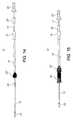
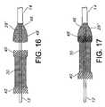
- FIGS. 16 and 17are exploded top planar views of the stent and the stent engaging portion of the stent loading and delivery device or system of FIGS. 14-15 .
- FIG. 18is a top planar view of different elements of the stent loading and delivery device or system of FIG. 14 in a dissembled configuration.
- FIGS. 19 and 20are alternate embodiments of the stent engaging portion of FIG. 16 .
- FIGS. 21-23depict an alternate embodiment of a handle for the delivery device of the present invention.
- FIG. 24is a cross-section view of a distal end on a tubular member of the device or system of FIG. 1 illustrating an inwardly beveled edge or end thereat.
- the present inventionrelates to an assembly and method for transporting and deploying a stent, or other intraluminary member as described herein, in a bodily passageway.
- the assemblyis suited for medical applications (particularly, endoscopic therapy) in the gastrointestinal tract, the biliary tract, the urinary tract, and the respiratory tract.
- a preferred embodiment of the present inventionis directed to an assembly and method for transporting, loading and delivering a self-expanding esophageal stent.
- the systemallows the clinician or user to easily load a stent into a delivery system with minimal effort and without damaging the stent.
- the assembly in accordance with the present inventioncould also be used in the neurological system (e.g., in the brain), the vascular system (e.g., in arteries or veins), in the cardiovascular system (e.g., in the heart) and in the like.
- Reference to bodily passagewaysmay be to passageways in any of the aforementioned tracts and systems or elsewhere in the body.
- distal and variants thereofrefer to a direction away from an operator of the subject invention
- references to the term “proximal” and variants thereofrefer to a direction towards the operator of the subject invention. Accordingly, when the terms “distal” and “proximal” are used herein in the context of an assembly device that is being deployed within a body, such as a human body, by an operator, the term “distal” refers to a location within or near the body that is further within the body than a location that is “proximal” to the operator.
- FIG. 1is a cross-sectional view of a stent loading and delivery system or device 10 according to the present invention.
- the system 10is particularly well suited for the loading, transluminal delivery and intraluminal deployment of a radially self-expanding prosthesis, such as a stent and/or a stent-graft.
- the system 10includes an elongate, flexible inner tubular member 12 , an intermediate tubular member 14 , which may also be also referred to as a stent loading member 14 , and an outer tubular member 16 , interrelated as shown.
- An outer tubular handle 18is disposed at the proximal end of the outer tubular member 16 .
- An intermediate tubular handle 20is disposed at the proximal end of the intermediate tubular member 14 .
- An inner tubular handle 22is disposed at the proximal end of the inner tubular member 12 .
- Manipulation or axial movement of the handles 18 , 20 and 22permits independent axial movement of the tubular members 12 , 14 , 16 , respectively.
- the intermediate tubular handle 20may be axially moved between distal and proximal positions to so axially move the intermediate tubular member 14 .
- Such movementmay be done while keeping the other handles 18 , 22 fixed or relatively fixed to allow independent or substantially independent movement of the intermediate tubular member 14 while the inner tubular member 12 and the outer tubular member 16 remain fixed or relatively fixed.
- the outer tubular handle 18may be axially moved between distal and proximal positions to so axially move the outer tubular member 16 while keeping the other handles 20 , 22 fixed or relatively fixed to allow independent or substantially independent movement of the outer tubular member 16 while the inner tubular member 12 and the intermediate tubular member 14 remain fixed or relatively fixed.
- the inner tubular handle 22may be axially moved between distal and proximal positions to so axially move the inner tubular member 12 while keeping the other handles 18 , 20 fixed or relatively fixed to allow independent or substantially independent movement of the inner tubular member 12 while the outer tubular member 16 and the intermediate tubular member 14 remain fixed or relatively fixed.
- the handles 18 , 20 and 22may be moved or manipulated in concert as a pair while keeping the third or non-paired handle fixed or relatively fixed to allow concurrent movement of two tubular members while keeping the third tubular member fixed or relatively fixed.
- the outer tubular member 16 and the intermediate tubular member 14may be moved in concert while keeping the inner tubular member 12 fixed or relatively fixed by manipulating the outer tubular handle 18 and the intermediate tubular handle 20 in concert while keeping the inner tubular handle 22 fixed or relatively fixed.
- the outer tubular member 16 and the inner tubular member 12may be moved in concert while the intermediate tubular member 14 keeping fixed or relatively fixed by manipulating the outer tubular handle 18 and the inner tubular handle 22 in concert while keeping the intermediate tubular handle 20 fixed or relatively fixed.
- the inner tubular member 12 and the intermediate tubular member 14may be moved in concert while keeping the outer tubular member 16 fixed or relatively fixed by manipulating the inner tubular handle 22 and in concert the intermediate tubular handle 20 while the outer tubular handle 18 keeping fixed or relatively fixed.
- the system 10advantageously includes a stent engaging member 28 disposed to or at the distal end of the intermediate tubular member 14 , and a stent holder 26 disposed on the inner tubular member 12 .
- the stent holder 26is disposed distally away from the stent engaging member 28 when intermediate handle 20 is proximally placed toward the outer handle 18 .
- the stent engaging member 28is useful for engaging a proximal end of a stent and compressingly loading the stent into the system 10 through axial manipulation of the system 10 , for example by axial movement of intermediate handle 20 .
- the stent holder 26is useful for securing the stent 30 within the system 10 , for example, against the outer tubular member 16 , until delivery of the stent 30 is desired within a bodily lumen (not shown).
- the system 10may further include a distal tip 24 disposed at the distal end of the inner tube 12 .
- the distal tip 24is useful for navigating bodily lumens without causing trauma to the same.
- the tubular members 12 , 14 , 16are formed of a body compatible material.
- the biocompatible materialis a biocompatible polymer.
- suitable biocompatible polymersinclude, but are not limited to, polyolefins such as polyethylene (PE), high density polyethylene (HDPE) and polypropylene (PP), polyolefin copolymers and terpolymers, polytetrafluoroethylene (PTFE), polyethylene terephthalate (PET), polyesters, polyamides, polyurethanes, polyurethaneureas, polypropylene and, polycarbonates, polyvinyl acetate, thermoplastic elastomers including polyether-polyester block copolymers and polyamide/polyether/polyesters elastomers, polyvinyl chloride, polystyrene, polyacrylate, polymethacrylate, polyacrylonitrile, polyacrylamide, silicone resins, combinations and copolymers thereof, and the like.
- the biocompatible polymersinclude polypropylene (PP), polytetrafluoroethylene (PTFE), polyethylene terephthalate (PET), high density polyethylene (HDPE), combinations and copolymers thereof, and the like.
- Materials for the tubular members 12 , 14 , 16may be the same or different.
- the tubular members 12 , 14 , 16may also have a surface treatment and/or coating on their inner surface, outer surface or portions thereof.
- a coatingneed not be applied to all of the tubular members 12 , 14 , 16 , and individual members may be coated, uncoated, partially coated, and the like.
- Useful coating materialsinclude any suitable biocompatible coating.
- suitable coatingsinclude polytetrafluoroethylene, silicone, hydrophilic materials, hydrogels, and the like.
- hydrophilic coating materialsinclude, but are not limited to, alkylene glycols, alkoxy polyalkylene glycols such as methoxypolyethylene oxide, polyoxyalkylene glycols such as polyethylene oxide, polyethylene oxide/polypropylene oxide copolymers, polyalkylene oxide-modified polydimethylsiloxanes, polyphosphazenes, poly(2-ethyl-2-oxazoline), homopolymers and copolymers of (meth)acrylic acid, poly(acrylic acid), copolymers of maleic anhydride including copolymers of methylvinyl ether and maleic acid, pyrrolidones including poly(vinylpyrrolidone) homopolymers and copolymers of vinyl pyrrolidone, poly(vinylsulfonic acid), acryl amides including poly(N-alkylacrylarnide), poly(vinyl alcohol), poly(ethyleneimine), polyamides, poly(carboxylic acids), methyl
- Non-limiting examples of suitable hydrogel coatingsinclude polyethylene oxide and its copolymers, polyvinylpyrrolidone and its derivatives; hydroxyethylacrylates or hydroxyethyl(meth)acrylates; polyacrylic acids; polyacrylamides; polyethylene maleic anhydride, combinations and copolymers thereof, and the like. Additional details of suitable coating materials and methods of coating medical devices with the same may be found in U.S. Pat. Nos. 6,447,835 and 6,890,348, the contents of which are incorporated herein by reference. Such coatings and/or surface treatment is desirably disposed on the inside or a portion thereof of the outer tubular member 16 to aid, if desired, in loading and/or deploying of the stent 30 .
- FIG. 2illustrates a radially self-expanding stent 30 that can be radially compressed and loaded into system 10 , transluminally delivered to an intended intraluminal treatment site, then released from the system for radial self-expansion against surrounding tissue. While the present invention can be applied to the delivery of many intraluminary devices, it is particularly suited for delivering the self-expanding stent 30 . Desirably, the stent 30 is capable of being radially compressed and longitudinally extended for implantation into a bodily lumen. The degree of elongation depends upon the structure and materials of the stent 30 and may be quite varied. The diameter of the stent 30 also may become several times smaller as it elongates.
- the stent 30be constructed to self-expand when released from a radially compressed state.
- Any stent that is capable of radial expansionmay be used in accordance with the present invention.
- a radially distensible stentwhich does not substantially longitudinally elongate upon radial contraction is also useful.
- a non-limiting example of such a stentis one formed from zig-zag or undulating wires or wire.
- various stent types and stent constructionsmay be employed in the invention, and the invention can be constructed to accommodate stents of various sizes and configurations.
- FIG. 3is an exploded or enlarged view of the stent 30 to depict the braiding of the stent filaments 32 .
- braiding and its variantsrefer to the diagonal intersection of elongate filaments 32 so that each filament passes alternately over and under one or more of the other filaments, which is commonly referred to as an intersection repeat pattern.
- Useful braiding patternsinclude, but are not limited to, a diamond braid having a 1/1 intersection repeat pattern, a regular braid having a 2/2 intersection repeat pattern or a hercules braid having a 3/3 intersection repeat pattern. The passing of the filaments under and over one and the other results in slidable filament crossings that are not interlooped or otherwise mechanically engaged or constrained.
- biocompatible materialsinclude, but are not limited to, biocompatible metals, biocompatible alloys, biocompatible polymeric materials, including synthetic biocompatible polymeric materials and bioabsorbable or biodegradable polymeric materials, materials made from or derived from natural sources and combinations thereof.
- Useful biocompatible metals or alloysinclude, but not limited to, nitinol, stainless steel, cobalt-based alloy such as Elgiloy, platinum, gold, titanium, tantalum, niobium, polymeric materials and combinations thereof.
- Useful synthetic biocompatible polymeric materialsinclude, but are not limited to, polyesters, including polyethylene terephthalate (PET) polyesters, polypropylenes, polyethylenes, polyurethanes, polyolefins, polyvinyls, polymethylacetates, polyamides, naphthalane dicarboxylene derivatives, silks and polytetrafluoroethylenes.
- PETpolyethylene terephthalate
- the polymeric materialsmay further include a metallic, a glass, ceramic or carbon constituent or fiber.
- bioabsorbable or biodegradable polymeric materialsinclude poly(L-lactide) (PLLA), poly(D,L-lactide) (PLA), poly(glycolide) (PGA), poly(L-lactide-co-D,L-lactide) (PLLA/PLA), poly(L-lactide-co-glycolide) (PLLA/PGA), poly(D,L-lactide-co-glycolide) (PLA/PGA), poly(glycolide-co-trimethylene carbonate) (PGA/PTMC), polydioxanone (PDS), Polycaprolactone (PCL), polyhydroxybutyrate (PHBT), poly(phosphazene) poly(D,L-lactide-co-caprolactone) PLA/PCL), poly(glycolide-co-caprolactone) (PGA/PCL), poly(phosphate ester) and the like.
- the stent 30may include materials made from or derived from natural sources, such as, but not limited to collagen, elastin, glycosaminoglycan, fibronectin and laminin, keratin, alginate, combinations thereof and the like.
- the stent 30may be made from polymeric materials which may also include radiopaque materials, such as metallic-based powders or ceramic-based powders, particulates or pastes which may be incorporated into the polymeric material.
- the radiopaque materialmay be blended with the polymer composition from which the polymeric wire is formed, and subsequently fashioned into the stent as described herein.
- the radiopaque materialmay be applied to the surface of the metal or polymer stent.
- Various radiopaque materials and their salts and derivativesmay be used including, without limitation, bismuth, barium and its salts such as barium sulfate, tantalum, tungsten, gold, platinum and titanium, to name a few.
- the stent 30may be selectively made radiopaque at desired areas along the stent or made be fully radiopaque, depending on the desired end-product and application. Further, portions of the stent 30 , for example stent filaments, may have an inner core of tantalum, gold, platinum, iridium or combination of thereof and an outer member or layer of nitinol to provide a composite filament for improved radiocapicity or visibility.
- the stent 30may also have improved external imaging under magnetic resonance imaging (MRI) and/or ultrasonic visualization techniques.
- MRImagnetic resonance imaging
- Materials for enhancing MRI visibilityinclude, but not be limited to, metal particles of gadolinium, iron, cobalt, nickel, dysprosium, dysprosium oxide, platinum, palladium, cobalt based alloys, iron based alloys, stainless steels, or other paramagnetic or ferromagnetic metals, gadolinium salts, gadolinium complexes, gadopentetate dimeglumine, compounds of copper, nickel, manganese, chromium, dysprosium and gadolinium.
- the stent 30 of the present inventionmay include ultrasound resonant material, such as but not limited to gold.
- Other features, which may be included with the stent 30 of the present invention,include radiopaque markers; surface modification for ultrasound, cell growth or therapeutic agent delivery; varying stiffness of the stent or stent components; varying geometry, such as tapering, flaring, bifurcation and the like; varying material; varying geometry of stent components, for example tapered stent filaments; and the like.
- the stent 30may have coverings, films, coatings, and the like disposed over, under or throughout or embedding the stent 30 .
- the stent 30may include a covering 34 , desirably a polymeric covering, disposed over the longitudinal length or a portion of the longitudinal length of the stent 30 .
- the stent 30may include a liner 36 , desirably a polymeric liner, disposed within the longitudinal length or a portion of the longitudinal length of the stent 30 .
- a covering 34desirably a polymeric covering
- the stent 30may include a both a covering 34 and a liner 36 , desirably a polymeric covering and liner which include the same or different polymeric materials, disposed over and within the longitudinal length or a portion of the longitudinal length of the stent 30 .
- the covering and the liner of FIG. 6may be a unitary film or coating that embeds or partially embeds the stent 30 .
- the covering 34 and/or the liner 36may be in the form of a tubular structure, for example composed of polymeric material and/or silicone.
- the covering 34 and/or the liner 36may also comprise any plastic or polymeric material, desirably a somewhat hard but flexible plastic or polymeric material.
- the covering 34 and/or the liner 36may be transparent or translucent, desirably substantially or partially transparent. Furthermore, the covering 34 and/or the liner 36 may be constructed of any suitable biocompatible materials, such as, but not limited to, polymers and polymeric materials, including fillers such as metals, carbon fibers, glass fibers or ceramics.
- Useful covering 34 and/or the liner 36 materialsinclude, but are not limited, polyethylene, polypropylene, polyvinyl chloride, polytetrafluoroethylene (PTFE), including expanded polytetrafluoroethylene (ePTFE), fluorinated ethylene propylene, fluorinated ethylene propylene, polyvinyl acetate, polystyrene, poly(ethylene terephthalate), naphthalene dicarboxylate derivatives, such as polyethylene naphthalate, polybutylene naphthalate, polytrimethylene naphthalate and trimethylenediol naphthalate, polyurethane, polyurea, silicone rubbers, polyamides, polyimides, polycarbonates, polyaldehydes, polyether ether ketone, natural rubbers, polyester copolymers, styrene-butadiene copolymers, polyethers, such as fully or partially halogenated polyethers, silicones, and copolymers and combinations
- the coating or coatingsmay be on the stent 30 , components of the stent 30 , and combinations thereof.
- the stent componentsin part or in total, may be temporary, for example bioabsorbable, biodegradable, and the like, or may be permanent (i.e., not substantially bioabsorbable or biodegradable), for example the above-described biocompatible metals, alloys and polymers.
- the stent 30includes braided polyester filaments, such as PET polyester filaments. Further, in some application, the stent 30 is desirably embedded in a coating of silicone. Additional details of such desirable stents are described in U.S. Pat. No. 6,162,244, the contents of which are incorporated herein by reference.
- the stent 30may be treated with a therapeutic agent or agents, such as, but not limited to, anti-thrombogenic agents (such as heparin, heparin derivatives, urokinase, and PPack (dextrophenylalanine proline arginine chloromethylketone); anti-proliferative agents (such as enoxaprin, angiopeptin, or monoclonal antibodies capable of blocking smooth muscle cell proliferation, hirudin, and acetylsalicylic acid); anti-inflammatory agents (such as dexamethasone, prednisolone, corticosterone, budesonide, estrogen, sulfasalazine, and mesalamine); antineoplastic/antiproliferative/anti-miotic agents (such as paclitaxel, 5-fluorouracil, cisplatin, vinblastine, vincristine, epothilones, endostatin, angiostatin and thymidine
- the stent 30may have a straight or substantially straight longitudinal portion 38 .
- the present inventionis not so limited.
- the stent 30may have a varied diameter, such as a flaring or tapering, along a portion or portion of its longitudinal expanse.
- a varied diameter stent 30is depicted in FIG. 8 .
- the stent 30 of FIG. 8may include a longitudinal length 38 and one or two flared ends 40 .
- the flared ends 40are enlarged flared ends having a diameter greater than the diameter of the longitudinal portion 38 of the stent 30 .
- the stent 30is not so limited, and for example the flared ends 40 , individually or in combination, may have a smaller diameter that the diameter of the longitudinal portion 38 of the stent 30 .
- the stent 30may be repositionable, removable and/or reconstrainable, and/or may include multiple interconnected or non-interconnected stents.
- the stent 30may include a loop or element, such as a suture loop or element, a polymeric loop or element, metallic or element, and combinations thereof which may be accessible to a user or practitioner, for example by the use of forceps, to reposition, remove and/or reconstrain the stent 30 after it has been delivered, partially or totally, to a bodily lumen.
- a loop or elementmay be integrally formed as part of the stent 30 .
- Further details of useful repositioning, removing and/or reconstraining loops or elementsmay be found in U.S. patent application Ser. No. 11/341,540, filed Jan. 27, 2006 and entitled “Stent Retrieval Member And Devices And Methods For Retrieving Or Repositioning A Stent” and in U.S. patent application Ser. No. 11/432,065, filed May 11, 2006, and entitled “Integrated Stent Respostioning And Retrieval Loop”, the contents of both of which are incorporated herein by reference.
- the inner tubular member 12may include a first tubular or distal portion 12 ′ and a second tubular or proximal portion 12 ′′.
- the distal portion 12 ′desirably has a larger diameter that the proximal portion 12 ′′ such that the proximal portion 12 ′′ is slidably disposed within the intermediate handle 20 while the distal portion 12 ′ is slidable through only a portion of the intermediate handle 20 .
- the intermediate handle 20may have a distal opening 42 larger than a proximal opening 44 .
- Such an arrangement servers, as described below,may function as a stop or limit for the axial movement of distal portion 12 ′ of the inner tubular member 12 relative to the intermediate tubular member 14 during loading of the stent 30 .
- FIG. 2depicts the stent 30 loading position for the system 10 of the present invention.
- the handles 18 and 20are disposed relatively towards one and the other such that the stent engaging member 28 is exposed and having its distal portion radially extended to a diameter larger, for example substantially larger, than the outside diameter of the outer tubular member 16 , for example at least about double the diameter.
- the stent engaging member 28which is depicted as being in the shape of a funnel, may be bonded, crimped or otherwise secured to the distal end of the intermediate member 14 .
- the engaging member 28has a truncated-conical shape, outwardly diverging in the distal direction from its proximal end, e.g., the proximal end being smaller than the distal end.
- the proximal endhas a diameter equal or substantially equal, including slightly larger, to the diameter of the intermediate tubular member 14 , but less than the diameter of the outer tubular member 16 .
- the engaging member 28may be formed of a thin polymeric film, for example, but not limited to, polyamide, such as polyamide 6-6 or nylon, PET or PTFE.
- the filmis desirably compliant, so that the funnel is capable of alternatively assuming an open configuration as seen in FIG. 1 for receiving a proximal end of stent 30 , and a collapsed configuration to allow engaging member 28 to be accommodated or contained within outer tubular member 16 .
- the engaging member 28is resilient and tends to assume the open configuration in the relaxed state when free of external stresses.
- the engaging member 28may be pliable, in particular radially distensible, mesh, weave or braid.
- the engaging member 28may be of any reasonable length and/or diameter to permit the loading of the stent 30 .
- the engaging member 28may have a beveled edge or profile for easier loading, removing or repositioning of the stent 30 .
- the engaging member 28may only partially circumferentially surround or encompass the intermediate tubular member 14 .
- the engaging member 28may be split or slit at either or both of its distal and proximal ends.
- the engaging member 28may comprise a film with pores.
- the intermediate tubular member 14may be pulled proximally and removed from between the inner and outer tubular members 12 , 16 .
- the intermediate tubular member 14 , and optionally the engaging member 28 and/or the intermediate handle 20may be split and pulled away from the inner tubular member 12 .
- the intermediate tubular member 14 , and optionally the engaging member 28 and/or the intermediate handle 20may be releasably disposed within the device or system 10 .
- the stent 30may be squeezed or radially contacted onto or about the inner tubular member 12 and pushed into the intermediate tubular member 14 which is disposed substantially within the outer tubular member 16 .
- the stent 30may be manually manipulated to load the stent 30 into the intermediate tubular member 14 .
- the stent 30may be disposed within a loading cartridge (not shown) for facilitating storage and delivery of the stent 30 into the intermediate tubular member 14 .
- the loading cartridgemay contain a piston or other axially movable member to facilitate stent movement. Details of suitable stent loading cartridges are further described in U.S.
- the handles 18 and 20may be kept in relative constant axial displacement from one and the other.
- the inner tubular member 12 and the intermediated tubular member 14are also kept in relative constant axial positions with the intermediate tubular member 14 being substantially disposed within the outer tubular member 16 .
- the intermediate tubular member 14need not be completely contained within the outer tubular member 18 , but rather a portion of the distal end of the intermediate tubular member 14 may be axially outside or distally disposed from the distal end of the outer tubular member 16 .
- the smaller distal opening 42 of the intermediate handle 20serves as a stop or an axially limiting device to keep the intermediate and inner tubular members 14 , 12 in relative constant axial arrangement during loading of the stent 30 .
- the inner handle 22is pulled away from the outer handle 18 to complete the loading.
- the stent 30is fully loaded into the system 10 of the present invention.
- the inner handle 22is pulled away axially away from the outer handle 18 in the stent loaded position as compared the handle 18 , 22 positions of FIGS. 1 and 2 .
- the outer tubular member 16is advanced distally toward the distal tip 24 to cover the stent 30 .
- the stent holder 26releasably secures the stent 30 between the inner tubular member 12 and the outer tubular member 16 .
- the stent holder 26is a hollow tubular band.
- the stent holder 26is a hollow tubular band that is free or substantially free of barbs, pins or protrusions which may engage and possible damage the stent 30 .
- the stent holder 26may be made of any suitable polymeric, rubber or metallic material.
- the stent holder 26may have a pattern, such as a surface pattern of indentations and/or protrusions, for facilitating securement of the stent 30 .
- the stent holder 26may have barbs, pins or protrusions which may engage the stent 30 .
- the device or system 10may include multiple stent holders 26 , either axially spaced apart or axially juxtaposed. Further, the stent holder 26 may not have to completely encompass the inner tubular member 12 , but may be only partially disposed around a circumferential portion of the inner tubular member 12 .
- the intermediate handle 20is advance proximally away from the outer handle 18 and proximally toward the inner handle 22 .
- the stent engaging member 28is moved axially away from the loaded stent 30 .
- the proximal end of the loaded stent 30is now free from the stent engaging member 28 .
- Such removal of the stent loading member 28 from the loaded stent 30facilitates delivery of the stent 30 as less force will be required to deploy the stent 30 .
- the loaded stent 30may be delivered to a bodily lumen (not shown) by advancing the outer handle 18 and correspondingly the outer tubular member 16 axially away from the distal tip 24 .
- the outer tubular member 16is retracted in a proximally axial direction to delivery the stent 30 .
- the intermediate handle 20 and the inner handle 22may be proximally and/or juxtaposingly disposed during certain stages of loading, constraining and/or deploying the stent 30 .
- the stent loading member handle 20may be integrated, for example mechanically integrated, with the inner tubular handle 22 to permit concurrent or simultaneous movement of the two handles 20 , 22 .
- Such mechanical integrationmay be achieved by matching and/or interlocking detents (not shown) on the two handles 20 , 22 .
- the mechanical integrationmay be achieved through the use of releasably interlocking detents (not shown) on the two handles 20 , 22 to permit, when desired, independent movement of the two handles 20 , 22 by mechanically releasing the detents from one and another and to permit, when desired, concurrent or simultaneous movement of the two handles 20 , 22 by mechanically engaging the detents with one and another.
- FIG. 12is an enlarged view of an embodiment of the proximal portion of the system 10 of the present invention.
- a step or cut-away portion of the inner tubular member 12may optionally serve as the above-described proximal portion 12 ′.
- a proximal portion 12 ′ in conjunction with the small proximal opening 44 of the intermediate handle 20serves as a stop during loading of the stent 30 into the system 10 of the present invention.
- the present inventionis not so limited.
- the distal and proximal openings 42 , 44 of the intermediate handle 20may be the same, substantially the same or about the same. In such a case, the intermediate handle 20 may be temporarily held against or near the outer handle 20 during loading of the stent 30 into the system 10 .
- FIGS. 14 and 15are a top planar view of the system 10 ′ of the present invention.
- This embodimentis substantially similar to the embodiment depicted in FIGS. 1 and 2 , except for the stent engaging member 28 ′.
- the stent engaging member 28 ′is a radially distensible basket, which can be made of similar materials or different materials of the stent 30 .
- the stent engaging member 28 ′has a truncated-conical shape 46 , outwardly diverging in the distal direction from its proximal end, which then merges, desirably seamlessly, into a straight or substantially straight cylindrical portion or rim portion 48 .
- the stent engaging member 28 ′may be radially distensible, i.e., it tends to assume an enlarged state when released from a contracted state, such as being compressed within the outer tubular member 16 .
- the stent engaging member 28 ′is especially useful for engaging the stent 30 having an outwardly extending end 40 .
- the stent engaging member 28 ′′may be simply made radially distensible and a truncated-conical shape by compressing a proximal portion of cylindrical stent engaging member 28 ′ onto the inner tubular member 14 .
- a portion 48 ′ of the rim portion 48 of the stent engaging member 28 ′′′may be inwardly biased, as depicted in FIG. 20 .
- Such alternate stent engaging designs 28 ′, 28 ′′, 28 ′′′are useful with the different stent configurations described herein.
- FIG. 18is a top planar view of the different elements of the system 10 ′ of the present invention in an “unassembled” stage.
- the inner tubular member 12is the longest member.
- the intermediate tubular member 14is smaller than the inner tubular member 12 , but longer than the outer tubular member 16 .
- the outer tubular member 16is typically the shortest of the members.
- the present inventionis not so limited and other tube length configurations may suitably be selected.
- the inner tubular member 22may be modified to enhance repositioning and/or retrieval of the stent 30 .
- the inner tubular handle 22 ′may include prongs 50 .
- Prongs 50are useful for securing a suture thread (not shown) to the outside of the handle 22 ′.
- the suture thread (not shown)may then be disposed within the cavity or lumen 50 of the handle 22 ′.
- the suture threadmay then be disposed within a lumen or cavity of the inner tubular member 12 and exit at an intermediate point whereby the suture thread may be secured to the stent 30 .
- the suture threadmay be manipulated by the user to reposition and/or the stent during or after delivery of the stent 40 . Upon completion of the stent delivery, the suture thread may be removed, for example by cutting, from the stent 30 .
- U.S. application Ser. No. 11/437,455entitled “Apparatus and Method for Loading and Delivering a Stent”, filed on same date herewith and, U.S. application Ser. No. 11/437,459, entitled “Apparatus and Method for Loading and Delivering a Stent Using a Suture Retaining Mechanism”, filed on same date herewith, the contents of which are incorporated herein by reference.
- tubular members 12 , 14 , 16may have a beveled or slanted edge at their distal end, proximal end or combinations thereof.
- tubular members 12 , 14 , 16may have an inwardly beveled edge 12 A, 14 A, 16 A at their respective distal ends 12 B, 14 B, 16 B.
- the beveled edge 16 Ais an inwardly beveled edge on the distal end 16 B of the outer tubular member 16 .
- Such beveled edges, in particular beveled edge 16 Aare useful in aiding the loading and/or deployment of the stent 30 . As depicted in FIG.
- an inwardly beveled edge or endis where the wall of the tubular member has a greater longitudinal expanse at its outer wall portion as compared to its inner wall portion.
- beveled edgesare smooth edges and accordingly may include rounded or smoothly contoured portions.
- a feature of the present inventionis that the stent loading is reversible. Suppose the user suspects that stent 30 was incorrectly positioned during loading, or determines that a different stent should be used. Stent 30 is easily unloaded, by operating handles 20 and 22 to advance inner tubular member 12 toward the open position. This progressively releases stent 30 from the outer tubular member 16 , whereupon the stent 30 may be removed from stent engaging member 28 by hand.
- the stent holder 26is distally spaced apart from the stent engaging member 28 . Such axial displacement allows the stent holder 26 to releasably hold the stent 30 within the system 10 even after the stent engaging member 28 is axially displaced away from the stent 30 . Such a feature allows, if desired, for a large portion of the stent 30 to be deployed and then be recaptured by the device 10 prior to complete deployment of the stent 30 . Such recapturing may be achieved with the above-described suture thread or by axially sliding the outer tubular member 16 over the stent 30 .
- the stent engaging member 28may be repositioned within the inner tubular member 12 and the outer tubular member 16 , for example, by axially advancing the member 28 to reposition the stent 30 therein between. Furthermore, the whole device 10 may be moved proximally or distally to reposition the stent 30 therein.
- the outer tubular member 16may be advanced over the stent 30 to a location distally past the tubular band 26 to releasably and securably set the position of the stent engaging member 28 and/or the stent loading member 14 relative to the position of the inner tubular member 12 .
- the outer tubular member 16may be retracted proximally past the tubular band 26 , thereby allowing repositioning of the stent 30 within the outer tubular member 16 and/or over the inner tubular member 12 .
- the outer tubular member 16may be re-advanced over the stent 30 and the tubular band 26 to releasably and securably reset the position of the stent engaging member 28 and/or the stent loading member 14 relative to the position of the inner tubular member 12 , thereby allowing reconstrainment of the stent.
- a stent loading and deployment device 10in one aspect of the present invention is provided.
- the device 10includes an outer elongate tubular member 16 having opposed proximal and distal ends; an inner elongate tubular member 12 having opposed proximal and distal ends and slidably disposed within the outer tubular member 16 , wherein, when the distal ends of the outer tubular member 16 and the inner tubular member 12 are axially aligned, a stent deployment region 13 is defined there in between; and a stent loading member 14 having opposed proximal and distal ends and slidably disposed between the outer tubular member 16 and the inner tubular member 12 .
- the distal end of the stent loading member 14is slidable to a distal position past the distal end of the outer tubular member 16 for receiving a stent 30 and is further slidable toward the proximal end of the outer tubular member 16 to a location past the stent deployment region 13 for disengagement of a stent 30 from the stent loading member 14 .
- the device 10may further include a stent engaging member 28 having opposed proximal and distal ends. Desirably, the proximal end is securably disposed to the distal end of the stent loading member 14 .
- the stent engaging member 28may have a truncated-conical shape, being smaller at its proximal end, i.e., outwardly diverging in a distal direction from its proximal end.
- the stent engaging member 28may be a thin film which is collapsible such that the stent engaging member 28 may be slidably contained within the outer tubular member 16 , or may be a radially distensible member 28 ′, 28 ′′, 28 ′′′ which is collapsible such that the stent engaging member 28 ′, 28 ′′, 28 ′′′ may be slidably contained within the outer tubular member 16 .
- the stent engaging memberis a polymeric member 28 , 28 ′, 28 ′′, 28 ′′′.
- the stent engaging member 28 ′, 28 ′′, 28 ′′′may include, in part or substantially, braided filaments.
- the braided filamentsmay include polymeric filaments, metallic filaments and any other suitable filaments.
- the braided filamentsmay be contained within a thin polymeric film.
- the stent loading member 14is an elongate tubular device.
- the device 10may further include a tubular band 26 disposed toward the distal end of the inner tubular member 12 for releasably securing a stent 30 in the stent deployment region 13 between the inner and outer tubular members 12 , 16 .
- the outer tubular member 16is slidable toward a distal position for releasing a stent 30 from the stent deployment region 13 .
- the device 10may further include an outer tubular handle 18 disposed at the distal end of the outer tubular member 16 ; an inner tubular handle 22 disposed at the proximal end of the inner tubular member 12 ; and a stent loading member handle 20 disposed at the proximal end of the stent loading member 14 .
- the stent loading member handle 20may be axially disposed between the outer tubular handle 18 and the inner tubular handle 22 .
- the outer member handle 18may be axially disposed before the proximal end of the inner tubular member 12 .
- the device 10 of this aspectis useful containing and releasing a radially distensible stent 30 .
- the radially distensible stent 30may be a polymeric stent, including a braided stent.
- a graftsuch as a covering, a liner, a film, a coating and combinations thereof, may be disposed over at least a portion of the stent.
- the stent 30is a braided polymeric stent and the graft is a silicone coating or film.
- a stent loading and deployment system 10in another aspect of the present invention, includes a radially distensible stent 30 ; an outer elongate tubular member 16 having opposed proximal and distal ends; an inner elongate tubular member 12 having opposed proximal and distal ends and slidably disposed within the outer tubular member 16 , wherein, when the distal ends of the outer tubular member 16 and the inner tubular member 12 are axially aligned, a stent deployment region 13 is defined there in between; and a stent loading member 14 having opposed proximal and distal ends and slidably disposed between the outer tubular member 16 and the inner tubular member 12 ; wherein the distal end of the stent loading member 14 is slidable to a distal position past the distal end of the outer tubular member 16 for receiving the stent 30 and is further slidable toward the proximal end of the outer tubular member 16 to a location past the s
- Use of the device 10is also contemplated by the present invention.
- Use of the device 10may include a method for loading a stent 30 into a delivery and deployment device 10 , which includes providing a radially distensible stent 30 having opposed proximal and distal ends; providing a delivery deployment device 10 , the device 10 including an outer elongate tubular member 16 having opposed proximal and distal ends; an inner elongate tubular member 12 having opposed proximal and distal ends and slidably disposed within the outer tubular member 16 , wherein, when the distal ends of the outer tubular member 16 and the inner tubular member 12 are axially aligned, a stent deployment region 13 is defined there in between; a stent loading member 14 having opposed proximal and distal ends and slidably disposed between the outer tubular member 16 and the inner tubular member 12 ; and optionally a stent engaging member 28 having opposed proximal and distal ends, wherein the prox
- the method or usemay further include providing a tubular band 26 disposed toward the distal end of the inner tubular member 12 for releasably securing the stent 30 in the stent deployment region 13 between the inner and outer tubular members 12 , 16 .
- the methodmay further include axially moving or sliding the outer tubular member 16 toward a proximal position for releasing the stent 30 from the stent deployment region 13 .
- the method or usemay yet further include providing an outer tubular handle 18 disposed at the proximal end of the outer tubular member 16 ; providing an inner tubular handle 22 disposed at the proximal end of the inner tubular member 12 ; and providing a stent loading member handle 20 disposed at the proximal end of the stent loading member 14 , wherein independent axial movement of the outer tubular member 16 , the inner tubular member 12 or the stent loading member 14 is achieved by manual manipulation of the handles 18 , 22 , 20 .
- the outer tubular member 16may be advanced over the stent 30 to a location distally past the tubular band 26 to releasably and securably set the position of the stent engaging member 28 and/or the stent loading member 14 relative to the position of the inner tubular member 12 . Further, the outer tubular member 16 may be retracted proximally past the tubular band 26 , thereby allowing repositioning of the stent 30 within the outer tubular member 16 and/or over the inner tubular member 12 .
- the outer tubular member 16may be re-advanced over the stent 30 and the tubular band 26 to releasably and securably reset the position of the stent engaging member 28 and/or the stent loading member 14 relative to the position of the inner tubular member 12 , thereby allowing reconstrainment of the stent.
Landscapes
- Health & Medical Sciences (AREA)
- Engineering & Computer Science (AREA)
- Biomedical Technology (AREA)
- Cardiology (AREA)
- Oral & Maxillofacial Surgery (AREA)
- Transplantation (AREA)
- Heart & Thoracic Surgery (AREA)
- Vascular Medicine (AREA)
- Life Sciences & Earth Sciences (AREA)
- Animal Behavior & Ethology (AREA)
- General Health & Medical Sciences (AREA)
- Public Health (AREA)
- Veterinary Medicine (AREA)
- Media Introduction/Drainage Providing Device (AREA)
- Prostheses (AREA)
Abstract
Description
Claims (35)
Priority Applications (8)
| Application Number | Priority Date | Filing Date | Title |
|---|---|---|---|
| US11/437,889US8535368B2 (en) | 2006-05-19 | 2006-05-19 | Apparatus for loading and delivering a stent |
| EP07794947.7AEP2018138B1 (en) | 2006-05-19 | 2007-05-16 | Apparatus and method for loading and delivering a stent |
| CA2650142ACA2650142C (en) | 2006-05-19 | 2007-05-16 | Apparatus and method for loading and delivering a stent |
| JP2009512048AJP5626676B2 (en) | 2006-05-19 | 2007-05-16 | Apparatus and method for loading and delivering a stent |
| PCT/US2007/011773WO2007136669A2 (en) | 2006-05-19 | 2007-05-16 | Apparatus and method for loading and delivering a stent |
| US14/027,777US8858614B2 (en) | 2006-05-19 | 2013-09-16 | Apparatus for loading and delivering a stent |
| US14/472,619US9943429B2 (en) | 2006-05-19 | 2014-08-29 | Apparatus for loading and delivering a stent |
| US15/938,569US10925761B2 (en) | 2006-05-19 | 2018-03-28 | Apparatus for loading and delivering a stent |
Applications Claiming Priority (1)
| Application Number | Priority Date | Filing Date | Title |
|---|---|---|---|
| US11/437,889US8535368B2 (en) | 2006-05-19 | 2006-05-19 | Apparatus for loading and delivering a stent |
Related Child Applications (1)
| Application Number | Title | Priority Date | Filing Date |
|---|---|---|---|
| US14/027,777ContinuationUS8858614B2 (en) | 2006-05-19 | 2013-09-16 | Apparatus for loading and delivering a stent |
Publications (2)
| Publication Number | Publication Date |
|---|---|
| US20070270932A1 US20070270932A1 (en) | 2007-11-22 |
| US8535368B2true US8535368B2 (en) | 2013-09-17 |
Family
ID=38657689
Family Applications (4)
| Application Number | Title | Priority Date | Filing Date |
|---|---|---|---|
| US11/437,889Expired - Fee RelatedUS8535368B2 (en) | 2006-05-19 | 2006-05-19 | Apparatus for loading and delivering a stent |
| US14/027,777Expired - Fee RelatedUS8858614B2 (en) | 2006-05-19 | 2013-09-16 | Apparatus for loading and delivering a stent |
| US14/472,619Active2027-08-12US9943429B2 (en) | 2006-05-19 | 2014-08-29 | Apparatus for loading and delivering a stent |
| US15/938,569Active2026-08-20US10925761B2 (en) | 2006-05-19 | 2018-03-28 | Apparatus for loading and delivering a stent |
Family Applications After (3)
| Application Number | Title | Priority Date | Filing Date |
|---|---|---|---|
| US14/027,777Expired - Fee RelatedUS8858614B2 (en) | 2006-05-19 | 2013-09-16 | Apparatus for loading and delivering a stent |
| US14/472,619Active2027-08-12US9943429B2 (en) | 2006-05-19 | 2014-08-29 | Apparatus for loading and delivering a stent |
| US15/938,569Active2026-08-20US10925761B2 (en) | 2006-05-19 | 2018-03-28 | Apparatus for loading and delivering a stent |
Country Status (5)
| Country | Link |
|---|---|
| US (4) | US8535368B2 (en) |
| EP (1) | EP2018138B1 (en) |
| JP (1) | JP5626676B2 (en) |
| CA (1) | CA2650142C (en) |
| WO (1) | WO2007136669A2 (en) |
Cited By (40)
| Publication number | Priority date | Publication date | Assignee | Title |
|---|---|---|---|---|
| US20070270931A1 (en)* | 2006-05-19 | 2007-11-22 | Boston Scientific Scimed, Inc. | Apparatus and method for loading and delivering a stent using a suture retaining mechanism |
| US20100049297A1 (en)* | 2008-08-21 | 2010-02-25 | C.R. Bard, Inc. | Method of loading a stent into a sheath |
| US20110060397A1 (en)* | 2008-05-09 | 2011-03-10 | C.R. Bard, Inc. | Method of loading a stent into a sheath |
| US20110288626A1 (en)* | 2010-05-20 | 2011-11-24 | Helmut Straubinger | Catheter system for introducing an expandable heart valve stent into the body of a patient, insertion system with a catheter system and medical device for treatment of a heart valve defect |
| US20140277565A1 (en)* | 2013-03-15 | 2014-09-18 | Boston Scientific Scimed, Inc. | Delivery Device for Partially Unconstrained Endoprosthesis |
| US8858614B2 (en)* | 2006-05-19 | 2014-10-14 | Boston Scientific Scimed, Inc. | Apparatus for loading and delivering a stent |
| USD755384S1 (en) | 2014-03-05 | 2016-05-03 | Edwards Lifesciences Cardiaq Llc | Stent |
| US9333073B2 (en) | 2009-04-15 | 2016-05-10 | Edwards Lifesciences Cardiaq Llc | Vascular implant and delivery method |
| US9339377B2 (en) | 2008-09-29 | 2016-05-17 | Edwards Lifesciences Cardiaq Llc | Body cavity prosthesis |
| US9480560B2 (en) | 2009-09-29 | 2016-11-01 | Edwards Lifesciences Cardiaq Llc | Method of securing an intralumenal frame assembly |
| US9554897B2 (en) | 2011-04-28 | 2017-01-31 | Neovasc Tiara Inc. | Methods and apparatus for engaging a valve prosthesis with tissue |
| US9572665B2 (en) | 2013-04-04 | 2017-02-21 | Neovasc Tiara Inc. | Methods and apparatus for delivering a prosthetic valve to a beating heart |
| US20170049568A1 (en)* | 2010-05-20 | 2017-02-23 | Jenavalve Technology, Inc. | Catheter system for introducing an expandable heart valve stent into the body of a patient, insertion system with a catheter system and medical device for treatment of a heart valve defect |
| US9597183B2 (en) | 2008-10-01 | 2017-03-21 | Edwards Lifesciences Cardiaq Llc | Delivery system for vascular implant |
| US9681951B2 (en) | 2013-03-14 | 2017-06-20 | Edwards Lifesciences Cardiaq Llc | Prosthesis with outer skirt and anchors |
| US9713529B2 (en) | 2011-04-28 | 2017-07-25 | Neovasc Tiara Inc. | Sequentially deployed transcatheter mitral valve prosthesis |
| US9717591B2 (en) | 2009-12-04 | 2017-08-01 | Edwards Lifesciences Corporation | Prosthetic valve for replacing mitral valve |
| US9730791B2 (en) | 2013-03-14 | 2017-08-15 | Edwards Lifesciences Cardiaq Llc | Prosthesis for atraumatically grasping intralumenal tissue and methods of delivery |
| US9770329B2 (en) | 2010-05-05 | 2017-09-26 | Neovasc Tiara Inc. | Transcatheter mitral valve prosthesis |
| US9949827B2 (en) | 2009-09-29 | 2018-04-24 | Edwards Lifesciences Cardiaq Llc | Replacement heart valves, delivery devices and methods |
| US9974669B2 (en) | 2005-11-10 | 2018-05-22 | Edwards Lifesciences Cardiaq Llc | Percutaneous heart valve |
| US10016275B2 (en) | 2012-05-30 | 2018-07-10 | Neovasc Tiara Inc. | Methods and apparatus for loading a prosthesis onto a delivery system |
| US10350062B2 (en) | 2016-07-21 | 2019-07-16 | Edwards Lifesciences Corporation | Replacement heart valve prosthesis |
| US10583002B2 (en) | 2013-03-11 | 2020-03-10 | Neovasc Tiara Inc. | Prosthetic valve with anti-pivoting mechanism |
| US10881542B2 (en) | 2016-04-05 | 2021-01-05 | Boston Scientific Scimed, Inc. | Stent delivery device |
| US10993805B2 (en) | 2008-02-26 | 2021-05-04 | Jenavalve Technology, Inc. | Stent for the positioning and anchoring of a valvular prosthesis in an implantation site in the heart of a patient |
| US11065138B2 (en) | 2016-05-13 | 2021-07-20 | Jenavalve Technology, Inc. | Heart valve prosthesis delivery system and method for delivery of heart valve prosthesis with introducer sheath and loading system |
| US11185405B2 (en) | 2013-08-30 | 2021-11-30 | Jenavalve Technology, Inc. | Radially collapsible frame for a prosthetic valve and method for manufacturing such a frame |
| US11197754B2 (en) | 2017-01-27 | 2021-12-14 | Jenavalve Technology, Inc. | Heart valve mimicry |
| US11337800B2 (en) | 2015-05-01 | 2022-05-24 | Jenavalve Technology, Inc. | Device and method with reduced pacemaker rate in heart valve replacement |
| US11357624B2 (en) | 2007-04-13 | 2022-06-14 | Jenavalve Technology, Inc. | Medical device for treating a heart valve insufficiency |
| US11517431B2 (en) | 2005-01-20 | 2022-12-06 | Jenavalve Technology, Inc. | Catheter system for implantation of prosthetic heart valves |
| US11564794B2 (en) | 2008-02-26 | 2023-01-31 | Jenavalve Technology, Inc. | Stent for the positioning and anchoring of a valvular prosthesis in an implantation site in the heart of a patient |
| US11589981B2 (en) | 2010-05-25 | 2023-02-28 | Jenavalve Technology, Inc. | Prosthetic heart valve and transcatheter delivered endoprosthesis comprising a prosthetic heart valve and a stent |
| US11684474B2 (en) | 2018-01-25 | 2023-06-27 | Edwards Lifesciences Corporation | Delivery system for aided replacement valve recapture and repositioning post-deployment |
| US11690743B2 (en) | 2019-02-15 | 2023-07-04 | Boston Scientific Scimed, Inc. | Stent delivery system |
| US11744692B2 (en) | 2017-02-23 | 2023-09-05 | Boston Scientific Scimed, Inc. | Medical drain device |
| US12121460B2 (en) | 2010-05-27 | 2024-10-22 | Idev Technologies, Inc. | Stent delivery system with pusher assembly |
| US12121461B2 (en) | 2015-03-20 | 2024-10-22 | Jenavalve Technology, Inc. | Heart valve prosthesis delivery system and method for delivery of heart valve prosthesis with introducer sheath |
| US12171658B2 (en) | 2022-11-09 | 2024-12-24 | Jenavalve Technology, Inc. | Catheter system for sequential deployment of an expandable implant |
Families Citing this family (150)
| Publication number | Priority date | Publication date | Assignee | Title |
|---|---|---|---|---|
| US7018401B1 (en) | 1999-02-01 | 2006-03-28 | Board Of Regents, The University Of Texas System | Woven intravascular devices and methods for making the same and apparatus for delivery of the same |
| US8425549B2 (en) | 2002-07-23 | 2013-04-23 | Reverse Medical Corporation | Systems and methods for removing obstructive matter from body lumens and treating vascular defects |
| EP1895951A1 (en)* | 2005-05-13 | 2008-03-12 | Alveolus Inc. | Delivery device allowing visual inspection of an intravascular site |
| GB0512319D0 (en)* | 2005-06-16 | 2005-07-27 | Angiomed Ag | Catheter device variable pusher |
| CN101495069A (en)* | 2006-07-07 | 2009-07-29 | 波士顿科学有限公司 | Endoprosthesis delivery system with stent holder |
| MX2009004291A (en) | 2006-10-22 | 2009-09-07 | Idev Technologies Inc | Methods for securing strand ends and the resulting devices. |
| KR101659197B1 (en) | 2006-10-22 | 2016-09-22 | 이데브 테크놀로지스, 아이엔씨. | Devices and methods for stent advancement |
| JP5248606B2 (en)* | 2007-06-26 | 2013-07-31 | セント ジュード メディカル インコーポレイテッド | Device for implanting a collapsible / expandable prosthetic heart valve |
| WO2009026563A2 (en) | 2007-08-23 | 2009-02-26 | Direct Flow Medical, Inc. | Translumenally implantable heart valve with formed in place support |
| DE102007043830A1 (en) | 2007-09-13 | 2009-04-02 | Lozonschi, Lucian, Madison | Heart valve stent |
| US9393137B2 (en)* | 2007-09-24 | 2016-07-19 | Boston Scientific Scimed, Inc. | Method for loading a stent into a delivery system |
| US8926680B2 (en) | 2007-11-12 | 2015-01-06 | Covidien Lp | Aneurysm neck bridging processes with revascularization systems methods and products thereby |
| US8088140B2 (en) | 2008-05-19 | 2012-01-03 | Mindframe, Inc. | Blood flow restorative and embolus removal methods |
| US9220522B2 (en) | 2007-10-17 | 2015-12-29 | Covidien Lp | Embolus removal systems with baskets |
| US11337714B2 (en) | 2007-10-17 | 2022-05-24 | Covidien Lp | Restoring blood flow and clot removal during acute ischemic stroke |
| US10123803B2 (en) | 2007-10-17 | 2018-11-13 | Covidien Lp | Methods of managing neurovascular obstructions |
| US8585713B2 (en) | 2007-10-17 | 2013-11-19 | Covidien Lp | Expandable tip assembly for thrombus management |
| US9198687B2 (en) | 2007-10-17 | 2015-12-01 | Covidien Lp | Acute stroke revascularization/recanalization systems processes and products thereby |
| US8066757B2 (en) | 2007-10-17 | 2011-11-29 | Mindframe, Inc. | Blood flow restoration and thrombus management methods |
| AU2008333855B2 (en) | 2007-12-04 | 2013-10-24 | Cook Medical Technologies Llc | Tapered loading system for implantable medical devices. |
| US8663320B2 (en)* | 2007-12-04 | 2014-03-04 | Cook Medical Technologies Llc | Storage and loading system for implantable medical devices |
| EP2252240B1 (en)* | 2008-01-14 | 2012-08-01 | Boston Scientific Scimed, Inc. | Stent delivery device with luer or clamp-type suture release apparatus |
| CA2711755A1 (en)* | 2008-01-24 | 2009-07-30 | Boston Scientific Scimed, Inc. | Apparatus and method for loading and delivering a stent having improved handles to control relative catheter component movement |
| US20090192588A1 (en)* | 2008-01-29 | 2009-07-30 | Taeoong Medical Co., Ltd | Biodegradable double stent |
| JP5457373B2 (en) | 2008-02-22 | 2014-04-02 | コヴィディエン リミテッド パートナーシップ | Device for blood flow recovery |
| ATE556679T1 (en) | 2008-04-09 | 2012-05-15 | Cook Medical Technologies Llc | CHARGER AND METHOD FOR EXPANDABLE INTRALUMINAL MEDICAL DEVICES |
| CN101977650A (en) | 2008-04-11 | 2011-02-16 | 曼德弗雷姆公司 | Monorail neural microcatheter for delivery of medical device for treatment of stroke, methods and products thereof |
| US9750625B2 (en) | 2008-06-11 | 2017-09-05 | C.R. Bard, Inc. | Catheter delivery device |
| GB0810749D0 (en) | 2008-06-11 | 2008-07-16 | Angiomed Ag | Catherter delivery device |
| US8359721B2 (en)* | 2008-09-04 | 2013-01-29 | Cook Medical Technologies Llc | Sliding split-sleeve implant compressor |
| US8151682B2 (en) | 2009-01-26 | 2012-04-10 | Boston Scientific Scimed, Inc. | Atraumatic stent and method and apparatus for making the same |
| WO2011022658A1 (en)* | 2009-08-20 | 2011-02-24 | Cook Incorporated | Loading apparatus and system for expandable intraluminal medical devices |
| US9439652B2 (en)* | 2009-08-24 | 2016-09-13 | Qualimed Innovative Medizinprodukte Gmbh | Implantation device with handle and method of use thereof |
| US20120238806A1 (en)* | 2009-08-24 | 2012-09-20 | Quali-Med Gmbh | Implantation system with handle and catheter and method of use thereof |
| JP5685256B2 (en) | 2009-09-21 | 2015-03-18 | メドトロニック,インコーポレイテッド | Stented transcatheter prosthetic heart valve delivery system and method |
| US8372133B2 (en)* | 2009-10-05 | 2013-02-12 | 480 Biomedical, Inc. | Polymeric implant delivery system |
| US9198783B2 (en)* | 2009-10-05 | 2015-12-01 | 480 Biomedical, Inc. | Polymeric implant delivery system |
| EP3300695B1 (en) | 2009-12-08 | 2023-05-24 | Avalon Medical Ltd. | Device and system for transcatheter mitral valve replacement |
| US20110144689A1 (en)* | 2009-12-15 | 2011-06-16 | Med Institute, Inc. | Occlusion Device |
| US9320597B2 (en)* | 2010-03-30 | 2016-04-26 | Medtronic, Inc. | Transcatheter prosthetic heart valve delivery system with recapturing feature and method |
| US8926692B2 (en)* | 2010-04-09 | 2015-01-06 | Medtronic, Inc. | Transcatheter prosthetic heart valve delivery device with partial deployment and release features and methods |
| US8998980B2 (en) | 2010-04-09 | 2015-04-07 | Medtronic, Inc. | Transcatheter prosthetic heart valve delivery system with recapturing feature and method |
| US8512400B2 (en) | 2010-04-09 | 2013-08-20 | Medtronic, Inc. | Transcatheter heart valve delivery system with reduced area moment of inertia |
| US8512401B2 (en)* | 2010-04-12 | 2013-08-20 | Medtronic, Inc. | Transcatheter prosthetic heart valve delivery system with funnel recapturing feature and method |
| US8579963B2 (en)* | 2010-04-13 | 2013-11-12 | Medtronic, Inc. | Transcatheter prosthetic heart valve delivery device with stability tube and method |
| US9603708B2 (en) | 2010-05-19 | 2017-03-28 | Dfm, Llc | Low crossing profile delivery catheter for cardiovascular prosthetic implant |
| WO2012036742A2 (en) | 2010-09-17 | 2012-03-22 | St. Jude Medical, Cardiology Division, Inc. | Assembly and method for loading a self-expanding collapsible heart valve |
| EP2648654B1 (en) | 2010-12-07 | 2024-02-14 | Merit Medical Systems, Inc. | Stent delivery systems |
| US20120172964A1 (en)* | 2010-12-30 | 2012-07-05 | Boston Scientific Scimed, Inc. | Stent Loading and Delivery Device Having a Loading Basket Lock Mechanism |
| EP2658483B1 (en)* | 2010-12-30 | 2018-07-11 | Boston Scientific Scimed, Inc. | Loading basket for a stent delivery system |
| SG191921A1 (en)* | 2011-01-14 | 2013-08-30 | Idev Technologies Inc | Stent delivery system with pusher assembly |
| US9486348B2 (en) | 2011-02-01 | 2016-11-08 | S. Jude Medical, Cardiology Division, Inc. | Vascular delivery system and method |
| WO2012106491A1 (en)* | 2011-02-02 | 2012-08-09 | St. Jude Medical, Inc. | System and method for loading a collapsile heart valve into a delivery device |
| BR112014002002A2 (en) | 2011-07-28 | 2017-02-21 | St Jude Medical Cardiology Div Inc | unit and method for charging a self-expanding prosthetic device to a delivery device |
| US8893370B2 (en) | 2011-07-28 | 2014-11-25 | St. Jude Medical, Cardiology Division, Inc. | System for loading a collapsible heart valve |
| EP4289398A3 (en) | 2011-08-11 | 2024-03-13 | Tendyne Holdings, Inc. | Improvements for prosthetic valves and related inventions |
| US8945145B2 (en)* | 2011-09-22 | 2015-02-03 | Medtronic, Inc. | Delivery system assemblies for implantable medical devices |
| US8945146B2 (en) | 2011-10-24 | 2015-02-03 | Medtronic, Inc. | Delivery system assemblies and associated methods for implantable medical devices |
| US9192496B2 (en) | 2011-10-31 | 2015-11-24 | Merit Medical Systems, Inc. | Systems and methods for sheathing an implantable device |
| US9216293B2 (en) | 2011-11-17 | 2015-12-22 | Medtronic, Inc. | Delivery system assemblies for implantable medical devices |
| US8721587B2 (en) | 2011-11-17 | 2014-05-13 | Medtronic, Inc. | Delivery system assemblies and associated methods for implantable medical devices |
| US9827092B2 (en) | 2011-12-16 | 2017-11-28 | Tendyne Holdings, Inc. | Tethers for prosthetic mitral valve |
| EP3281608B1 (en) | 2012-02-10 | 2020-09-16 | CVDevices, LLC | Medical product comprising a frame and visceral pleura |
| DE202012002340U1 (en)* | 2012-03-03 | 2012-04-16 | Peter Osypka | Vascular support of high flexibility with predetermined breaking point |
| US9445897B2 (en) | 2012-05-01 | 2016-09-20 | Direct Flow Medical, Inc. | Prosthetic implant delivery device with introducer catheter |
| US20140012101A1 (en)* | 2012-07-05 | 2014-01-09 | Microtech Medical Technologies Ltd. | Direct deployment system and method |
| WO2014022124A1 (en) | 2012-07-28 | 2014-02-06 | Tendyne Holdings, Inc. | Improved multi-component designs for heart valve retrieval device, sealing structures and stent assembly |
| WO2014021905A1 (en) | 2012-07-30 | 2014-02-06 | Tendyne Holdings, Inc. | Improved delivery systems and methods for transcatheter prosthetic valves |
| EP2710985A3 (en)* | 2012-09-20 | 2016-01-13 | Biotronik AG | Implant, system formed of an implant and a catheter, and method for producing such a system |
| CA2874563C (en)* | 2012-10-17 | 2021-01-12 | Angiomed Gmbh & Co. Medizintechnik Kg | Hand unit to release a self-expanding implant |
| CN103083123B (en)* | 2013-01-11 | 2015-02-11 | 威海维心医疗设备有限公司 | Esophagus support conveyor |
| CA2900862C (en) | 2013-02-11 | 2017-10-03 | Cook Medical Technologies Llc | Expandable support frame and medical device |
| US11224510B2 (en) | 2013-04-02 | 2022-01-18 | Tendyne Holdings, Inc. | Prosthetic heart valve and systems and methods for delivering the same |
| US10463489B2 (en) | 2013-04-02 | 2019-11-05 | Tendyne Holdings, Inc. | Prosthetic heart valve and systems and methods for delivering the same |
| US10478293B2 (en) | 2013-04-04 | 2019-11-19 | Tendyne Holdings, Inc. | Retrieval and repositioning system for prosthetic heart valve |
| WO2014179767A2 (en) | 2013-05-03 | 2014-11-06 | C.R. Bard, Inc. | Peelable protective sheath |
| US9610159B2 (en) | 2013-05-30 | 2017-04-04 | Tendyne Holdings, Inc. | Structural members for prosthetic mitral valves |
| EP2813195A1 (en)* | 2013-06-13 | 2014-12-17 | Cardiatis S.A. | Stent delivery system |
| CN105658178B (en) | 2013-06-25 | 2018-05-08 | 坦迪尼控股股份有限公司 | Thrombus management and structural compliance features for prosthetic heart valves |
| WO2015013666A1 (en) | 2013-07-26 | 2015-01-29 | Cardiaq Valve Technologies, Inc. | Systems and methods for sealing openings in an anatomical wall |
| AU2014296087B2 (en) | 2013-08-01 | 2019-08-01 | Tendyne Holdings, Inc. | Epicardial anchor devices and methods |
| WO2015057838A1 (en) | 2013-10-15 | 2015-04-23 | Boston Scientific Scimed, Inc. | Methods and systems for loading and delivering a stent |
| WO2015058039A1 (en) | 2013-10-17 | 2015-04-23 | Robert Vidlund | Apparatus and methods for alignment and deployment of intracardiac devices |
| EP3062744B1 (en) | 2013-10-28 | 2020-01-22 | Tendyne Holdings, Inc. | Prosthetic heart valve and systems for delivering the same |
| US9526611B2 (en) | 2013-10-29 | 2016-12-27 | Tendyne Holdings, Inc. | Apparatus and methods for delivery of transcatheter prosthetic valves |
| US9974543B2 (en)* | 2013-12-06 | 2018-05-22 | W. L. Gore & Associates, Inc. | Anastomotic connectors |
| US11027106B2 (en)* | 2014-01-26 | 2021-06-08 | Butterfly Medical Ltd. | Dilating device and method for prostatic urethra |
| WO2015120122A2 (en) | 2014-02-05 | 2015-08-13 | Robert Vidlund | Apparatus and methods for transfemoral delivery of prosthetic mitral valve |
| US9986993B2 (en) | 2014-02-11 | 2018-06-05 | Tendyne Holdings, Inc. | Adjustable tether and epicardial pad system for prosthetic heart valve |
| JP6865037B2 (en) | 2014-03-10 | 2021-04-28 | テンダイン ホールディングス,インコーポレイテッド | Devices and methods for positioning the artificial mitral valve and monitoring the tether load of the artificial mitral valve |
| US20160019485A1 (en)* | 2014-07-16 | 2016-01-21 | Wipro Limited | Method and system for scheduling meetings |
| US9877855B2 (en)* | 2014-07-25 | 2018-01-30 | Cook Medical Technologies Llc | Method of loading and delivering a self-expanding stent |
| JP2017530814A (en)* | 2014-10-13 | 2017-10-19 | シメティス・ソシエテ・アノニムSymetis Sa | Catheter delivery system for stent valves |
| AU2016205371B2 (en) | 2015-01-07 | 2019-10-10 | Tendyne Holdings, Inc. | Prosthetic mitral valves and apparatus and methods for delivery of same |
| AU2016209053B2 (en) | 2015-01-23 | 2020-04-16 | Contego Medical, Inc. | Interventional device having an integrated embolic filter and associated methods |
| AU2016215197B2 (en) | 2015-02-05 | 2020-01-02 | Tendyne Holdings Inc. | Expandable epicardial pads and devices and methods for their delivery |
| WO2016141295A1 (en) | 2015-03-05 | 2016-09-09 | Merit Medical Systems, Inc. | Vascular prosthesis deployment device and method of use |
| CA2983002C (en) | 2015-04-16 | 2023-07-04 | Tendyne Holdings, Inc. | Apparatus and methods for delivery, repositioning, and retrieval of transcatheter prosthetic valves |
| EP3288493B1 (en)* | 2015-04-29 | 2022-11-30 | Micro Medical Solutions, Inc. | Stent delivery system |
| AU2016271473B2 (en)* | 2015-06-05 | 2020-04-23 | Tendyne Holdings, Inc. | Apical control of transvascular delivery of prosthetic mitral valve |
| EP3313330A4 (en)* | 2015-06-29 | 2019-03-20 | 480 Biomedical, Inc. | SUPPORT LOADING AND DISTRIBUTION SYSTEMS |
| CN105105870B (en)* | 2015-07-27 | 2023-12-01 | 上海微创医疗器械(集团)有限公司 | Heart valve conveying device |
| US10154905B2 (en)* | 2015-08-07 | 2018-12-18 | Medtronic Vascular, Inc. | System and method for deflecting a delivery catheter |
| WO2017027376A1 (en)* | 2015-08-07 | 2017-02-16 | Massachusetts Institute Of Technology | Subcutaneous drug delivery device with manual activation and deactivation of drug release |
| US12082845B2 (en)* | 2015-09-04 | 2024-09-10 | The Trustees Of The University Of Pennsylvania | Systems and methods for percutaneous removal of objects from an internal body space |
| US10470906B2 (en) | 2015-09-15 | 2019-11-12 | Merit Medical Systems, Inc. | Implantable device delivery system |
| US10327894B2 (en) | 2015-09-18 | 2019-06-25 | Tendyne Holdings, Inc. | Methods for delivery of prosthetic mitral valves |
| CN113952095B (en) | 2015-09-18 | 2025-06-06 | 微仙美国有限公司 | Implant retention, detachment and delivery systems |
| WO2017087675A1 (en) | 2015-11-20 | 2017-05-26 | Cardiac Pacemakers, Inc. | Delivery devices and methods for leadless cardiac devices |
| AU2016355676B2 (en) | 2015-11-20 | 2018-12-13 | Cardiac Pacemakers, Inc. | Delivery devices and methods for leadless cardiac devices |
| AU2016362474B2 (en) | 2015-12-03 | 2021-04-22 | Tendyne Holdings, Inc. | Frame features for prosthetic mitral valves |
| WO2017117109A1 (en) | 2015-12-28 | 2017-07-06 | Tendyne Holdings, Inc. | Atrial pocket closures for prosthetic heart valves |
| SG11201806005QA (en)* | 2016-02-19 | 2018-09-27 | Joline Gmbh & Co Kg | Stent delivery system |
| US10660776B2 (en) | 2016-04-11 | 2020-05-26 | Boston Scientific Scimed, Inc. | Stent delivery system with collapsible loading frame |
| US10470877B2 (en) | 2016-05-03 | 2019-11-12 | Tendyne Holdings, Inc. | Apparatus and methods for anterior valve leaflet management |
| CN109152634A (en) | 2016-05-09 | 2019-01-04 | 扩凡科技有限公司 | Facility for storing and loading self-expanding stent-like devices |
| US11039921B2 (en) | 2016-06-13 | 2021-06-22 | Tendyne Holdings, Inc. | Sequential delivery of two-part prosthetic mitral valve |
| JP6968113B2 (en) | 2016-06-30 | 2021-11-17 | テンダイン ホールディングス,インコーポレイテッド | Transapical delivery device for artificial heart valves |
| WO2018013515A1 (en) | 2016-07-12 | 2018-01-18 | Tendyne Holdings, Inc. | Apparatus and methods for trans-septal retrieval of prosthetic heart valves |
| CN106264807B (en)* | 2016-08-16 | 2018-01-09 | 常州乐奥医疗科技股份有限公司 | A kind of intravascular stent induction system |
| CN107157621B (en)* | 2016-09-23 | 2024-07-30 | 杭州启明医疗器械股份有限公司 | Conveying system capable of recycling and repeatedly positioning interventional instrument |
| CN115054413A (en) | 2016-09-29 | 2022-09-16 | 美国医疗设备有限公司 | Method of adjusting effective length of stent and prosthesis delivery catheter assembly |
| US11426276B2 (en)* | 2016-10-12 | 2022-08-30 | Medtronic Vascular, Inc. | Stented prosthetic heart valve delivery system having an expandable bumper |
| AU2017201160B1 (en) | 2017-02-21 | 2018-04-26 | Cook Medical Technologies Llc | A medical device for temporary deployment into a bodily lumen |
| US11628078B2 (en) | 2017-03-15 | 2023-04-18 | Merit Medical Systems, Inc. | Transluminal delivery devices and related kits and methods |
| EP4467111A3 (en) | 2017-03-15 | 2025-03-05 | Merit Medical Systems, Inc. | Transluminal stents |
| USD836194S1 (en) | 2017-03-21 | 2018-12-18 | Merit Medical Systems, Inc. | Stent deployment device |
| WO2018232134A1 (en) | 2017-06-16 | 2018-12-20 | Boston Scientific Scimed, Inc. | Stent and sleeve deployment |
| CN111050702B (en) | 2017-07-13 | 2022-07-05 | 坦迪尼控股股份有限公司 | Prosthetic heart valve and devices and methods for delivering the prosthetic heart valve |
| EP3654883A1 (en) | 2017-07-18 | 2020-05-27 | St. Jude Medical, Cardiology Division, Inc. | Flushable loading base |
| AU2018323900A1 (en) | 2017-08-28 | 2020-02-27 | Tendyne Holdings, Inc. | Prosthetic heart valves with tether coupling features |
| JP2019102646A (en)* | 2017-12-01 | 2019-06-24 | トヨタ自動車株式会社 | Semiconductor device |
| KR102489167B1 (en) | 2018-04-09 | 2023-01-17 | 보스톤 싸이엔티픽 싸이메드 인코포레이티드 | Stent delivery system with reduced deployment force |
| JP7407812B2 (en) | 2018-07-06 | 2024-01-04 | クック・メディカル・テクノロジーズ・リミテッド・ライアビリティ・カンパニー | Storage devices, loading devices, feeding systems, kits and related methods |
| US11389627B1 (en) | 2018-10-02 | 2022-07-19 | Lutonix Inc. | Balloon protectors, balloon-catheter assemblies, and methods thereof |
| WO2021113395A1 (en)* | 2019-12-02 | 2021-06-10 | Venarum Medical, Llc | Process for catheter loading an implantable venous valve and apparatus |
| EP3831343B1 (en) | 2019-12-05 | 2024-01-31 | Tendyne Holdings, Inc. | Braided anchor for mitral valve |
| US11648114B2 (en) | 2019-12-20 | 2023-05-16 | Tendyne Holdings, Inc. | Distally loaded sheath and loading funnel |
| US11951002B2 (en) | 2020-03-30 | 2024-04-09 | Tendyne Holdings, Inc. | Apparatus and methods for valve and tether fixation |
| EP4185239A4 (en) | 2020-07-24 | 2024-08-07 | Merit Medical Systems, Inc. | ESOPHAGEAL STENT PROSTHESES AND RELATED METHODS |
| EP4199860A1 (en) | 2020-08-19 | 2023-06-28 | Tendyne Holdings, Inc. | Fully-transseptal apical pad with pulley for tensioning |
| IL301184A (en)* | 2020-09-30 | 2023-05-01 | Edwards Lifesciences Corp | Heart valve conduction system |
| CA3194910A1 (en) | 2020-10-26 | 2022-05-05 | Tiffany ETHRIDGE | Esophageal stents with helical thread |
| CA3157546C (en)* | 2020-12-18 | 2023-06-13 | Vesalius Cardiovascular Inc. | Device for stabilizing catheters and method of use thereof |
| US20230038490A1 (en)* | 2021-08-06 | 2023-02-09 | Medtronic Vascular, Inc. | Transcatheter valve recapture devices and methods |
| JP7681802B2 (en) | 2021-10-28 | 2025-05-22 | ボストン サイエンティフィック サイムド,インコーポレイテッド | Device Delivery via Biliary Access Device |
| CN115919521A (en)* | 2022-12-07 | 2023-04-07 | 江苏博朗森思医疗器械有限公司 | Intestinal anti-absorber removal device |
| CN116370154B (en)* | 2023-05-09 | 2023-09-05 | 杭州启明医疗器械股份有限公司 | Sheath and delivery system for loading and retrieval of prosthetic implants |
| CN116585072B (en)* | 2023-05-16 | 2024-03-26 | 晨兴(南通)医疗器械有限公司 | Valve recovery device and method of use |
| CN116616960B (en)* | 2023-06-01 | 2025-05-23 | 佰仁医疗(江苏)有限公司 | Heart valve transporter |
Citations (14)
| Publication number | Priority date | Publication date | Assignee | Title |
|---|---|---|---|---|
| US5645559A (en)* | 1992-05-08 | 1997-07-08 | Schneider (Usa) Inc | Multiple layer stent |
| US5683451A (en)* | 1994-06-08 | 1997-11-04 | Cardiovascular Concepts, Inc. | Apparatus and methods for deployment release of intraluminal prostheses |
| US5749921A (en)* | 1996-02-20 | 1998-05-12 | Medtronic, Inc. | Apparatus and methods for compression of endoluminal prostheses |
| US5906619A (en)* | 1997-07-24 | 1999-05-25 | Medtronic, Inc. | Disposable delivery device for endoluminal prostheses |
| WO1999051166A1 (en) | 1998-04-02 | 1999-10-14 | Salviac Limited | Delivery catheter |
| WO2000041525A2 (en) | 1999-01-11 | 2000-07-20 | Scimed Life Systems, Inc. | Self-expanding stent delivery system with two sheaths |
| US20030040789A1 (en)* | 1998-03-31 | 2003-02-27 | Darragh Colgan | Stent delivery system |
| US20030199821A1 (en)* | 2001-03-14 | 2003-10-23 | Scimed Life Systems, Inc. | Rapid exchange stent delivery system and associated components |
| US6645239B1 (en)* | 1999-08-18 | 2003-11-11 | Jae-Hyung Park | Flexible and self-expandable stent and inserting device for such stents |
| US20040167606A1 (en)* | 1998-08-14 | 2004-08-26 | Chouinard Paul F. | Stent-graft-membrane and method of making the same |
| US20040230284A1 (en)* | 2003-05-16 | 2004-11-18 | Headley F. Anthony | Dilatation and stent delivery system and related methods |
| US6902575B2 (en)* | 2001-12-18 | 2005-06-07 | Linvatec Biomaterials, Inc. | Stent delivery apparatus and method |
| US6945990B2 (en)* | 2003-08-16 | 2005-09-20 | Medtronic Vascular, Inc. | Double sheath deployment system |
| US20060184226A1 (en)* | 2005-02-16 | 2006-08-17 | Michael Austin | Delivery system for self-expanding stent, a method of using the delivery system, and a method of producing the delivery system |
Family Cites Families (38)
| Publication number | Priority date | Publication date | Assignee | Title |
|---|---|---|---|---|
| SE467948B (en)* | 1991-06-14 | 1992-10-12 | Ams Medinvent Sa | DEVICE FOR TRANSLUMINAL REMOVAL OR IMPLANTATION OF A STENT AND APPARATUS INCLUDING A SOUND DEVICE |
| US5201757A (en)* | 1992-04-03 | 1993-04-13 | Schneider (Usa) Inc. | Medial region deployment of radially self-expanding stents |
| US5312417A (en)* | 1992-07-29 | 1994-05-17 | Wilk Peter J | Laparoscopic cannula assembly and associated method |
| US5549626A (en)* | 1994-12-23 | 1996-08-27 | New York Society For The Ruptured And Crippled Maintaining The Hospital For Special Surgery | Vena caval filter |
| US6306144B1 (en) | 1996-11-01 | 2001-10-23 | Scimed Life Systems, Inc. | Selective coating of a balloon catheter with lubricious material for stent deployment |
| US5676671A (en)* | 1995-04-12 | 1997-10-14 | Inoue; Kanji | Device for introducing an appliance to be implanted into a catheter |
| JP3645911B2 (en) | 1996-03-29 | 2005-05-11 | ヴィリー リュッシュ アー・ゲー | Stent |
| US5800517A (en)* | 1996-08-19 | 1998-09-01 | Scimed Life Systems, Inc. | Stent delivery system with storage sleeve |
| US6776792B1 (en)* | 1997-04-24 | 2004-08-17 | Advanced Cardiovascular Systems Inc. | Coated endovascular stent |
| US6340367B1 (en)* | 1997-08-01 | 2002-01-22 | Boston Scientific Scimed, Inc. | Radiopaque markers and methods of using the same |
| US6174330B1 (en) | 1997-08-01 | 2001-01-16 | Schneider (Usa) Inc | Bioabsorbable marker having radiopaque constituents |
| WO1999039648A1 (en)* | 1998-02-10 | 1999-08-12 | Dubrul William R | Entrapping apparatus and method for use |
| DE59812219D1 (en) | 1998-03-04 | 2004-12-09 | Schneider Europ Gmbh Buelach | Device for inserting an endoprosthesis into a catheter shaft |
| US6960222B2 (en)* | 1998-03-13 | 2005-11-01 | Gore Enterprise Holdins, Inc. | Catheter having a funnel-shaped occlusion balloon of uniform thickness and methods of manufacture |
| US6776791B1 (en)* | 1998-04-01 | 2004-08-17 | Endovascular Technologies, Inc. | Stent and method and device for packing of same |
| US6149680A (en)* | 1998-06-04 | 2000-11-21 | Scimed Life Systems, Inc. | Stent loading tool |
| US6458151B1 (en)* | 1999-09-10 | 2002-10-01 | Frank S. Saltiel | Ostial stent positioning device and method |
| US6183503B1 (en)* | 1999-09-17 | 2001-02-06 | Applied Medical Resources Corporation | Mesh stent with variable hoop strength |
| US6447835B1 (en) | 2000-02-15 | 2002-09-10 | Scimed Life Systems, Inc. | Method of coating polymeric tubes used in medical devices |
| US6824545B2 (en)* | 2000-06-29 | 2004-11-30 | Concentric Medical, Inc. | Systems, methods and devices for removing obstructions from a blood vessel |
| US20020188314A1 (en)* | 2001-06-07 | 2002-12-12 | Microvena Corporation | Radiopaque distal embolic protection device |
| DE10148185B4 (en)* | 2001-09-28 | 2005-08-11 | Alveolus, Inc. | Instrument for implanting vascular prostheses |
| US20030083730A1 (en)* | 2001-10-25 | 2003-05-01 | Scimed Life Systems, Inc. | Loading cartridge for self-expanding stent |
| US7585309B2 (en)* | 2002-05-16 | 2009-09-08 | Boston Scientific Scimed, Inc. | Aortic filter |
| US7637934B2 (en)* | 2003-03-31 | 2009-12-29 | Merit Medical Systems, Inc. | Medical appliance optical delivery and deployment apparatus and method |
| US7473271B2 (en)* | 2003-04-11 | 2009-01-06 | Boston Scientific Scimed, Inc. | Stent delivery system with securement and deployment accuracy |
| US7241308B2 (en)* | 2003-06-09 | 2007-07-10 | Xtent, Inc. | Stent deployment systems and methods |
| US20040267281A1 (en)* | 2003-06-25 | 2004-12-30 | Eran Harari | Delivery system for self-expandable diverter |
| CA2556935A1 (en)* | 2004-02-19 | 2005-09-01 | Applied Medical Resources Corporation | Embolectomy capture sheath |
| US9301862B2 (en) | 2005-01-28 | 2016-04-05 | Boston Scientific Scimed, Inc. | Stent retrieval member and devices and methods for retrieving or repositioning a stent |
| EP1887974B1 (en) | 2005-05-13 | 2018-04-25 | Boston Scientific Limited | Integrated stent repositioning and retrieval loop |
| US8038704B2 (en)* | 2005-07-27 | 2011-10-18 | Paul S. Sherburne | Stent and other objects removal from a body |
| US7837702B2 (en)* | 2005-12-21 | 2010-11-23 | Nexeon Medsystems, Inc. | Interventional catheter for retrograde use having embolic protection capability and methods of use |
| US7846175B2 (en)* | 2006-04-03 | 2010-12-07 | Medrad, Inc. | Guidewire and collapsable filter system |
| US8834550B2 (en) | 2006-05-19 | 2014-09-16 | Boston Scientific Scimed, Inc. | Apparatus and method for loading and delivering a stent using a suture retaining mechanism |
| US8535368B2 (en)* | 2006-05-19 | 2013-09-17 | Boston Scientific Scimed, Inc. | Apparatus for loading and delivering a stent |
| US8753384B2 (en) | 2006-05-19 | 2014-06-17 | Boston Scientific Scimed, Inc. | Apparatus and method for loading and delivering a stent |
| WO2015057838A1 (en)* | 2013-10-15 | 2015-04-23 | Boston Scientific Scimed, Inc. | Methods and systems for loading and delivering a stent |
- 2006
- 2006-05-19USUS11/437,889patent/US8535368B2/ennot_activeExpired - Fee Related
- 2007
- 2007-05-16WOPCT/US2007/011773patent/WO2007136669A2/enactiveApplication Filing
- 2007-05-16JPJP2009512048Apatent/JP5626676B2/enactiveActive
- 2007-05-16EPEP07794947.7Apatent/EP2018138B1/enactiveActive
- 2007-05-16CACA2650142Apatent/CA2650142C/ennot_activeExpired - Fee Related
- 2013
- 2013-09-16USUS14/027,777patent/US8858614B2/ennot_activeExpired - Fee Related
- 2014
- 2014-08-29USUS14/472,619patent/US9943429B2/enactiveActive
- 2018
- 2018-03-28USUS15/938,569patent/US10925761B2/enactiveActive
Patent Citations (16)
| Publication number | Priority date | Publication date | Assignee | Title |
|---|---|---|---|---|
| US5645559A (en)* | 1992-05-08 | 1997-07-08 | Schneider (Usa) Inc | Multiple layer stent |
| US5683451A (en)* | 1994-06-08 | 1997-11-04 | Cardiovascular Concepts, Inc. | Apparatus and methods for deployment release of intraluminal prostheses |
| US5749921A (en)* | 1996-02-20 | 1998-05-12 | Medtronic, Inc. | Apparatus and methods for compression of endoluminal prostheses |
| US5906619A (en)* | 1997-07-24 | 1999-05-25 | Medtronic, Inc. | Disposable delivery device for endoluminal prostheses |
| US20030040789A1 (en)* | 1998-03-31 | 2003-02-27 | Darragh Colgan | Stent delivery system |
| WO1999051166A1 (en) | 1998-04-02 | 1999-10-14 | Salviac Limited | Delivery catheter |
| JP2002510525A (en) | 1998-04-02 | 2002-04-09 | サルヴィアック・リミテッド | Delivery catheter |
| US20040167606A1 (en)* | 1998-08-14 | 2004-08-26 | Chouinard Paul F. | Stent-graft-membrane and method of making the same |
| WO2000041525A2 (en) | 1999-01-11 | 2000-07-20 | Scimed Life Systems, Inc. | Self-expanding stent delivery system with two sheaths |
| US6645239B1 (en)* | 1999-08-18 | 2003-11-11 | Jae-Hyung Park | Flexible and self-expandable stent and inserting device for such stents |
| US20030199821A1 (en)* | 2001-03-14 | 2003-10-23 | Scimed Life Systems, Inc. | Rapid exchange stent delivery system and associated components |
| US6902575B2 (en)* | 2001-12-18 | 2005-06-07 | Linvatec Biomaterials, Inc. | Stent delivery apparatus and method |
| US20040230284A1 (en)* | 2003-05-16 | 2004-11-18 | Headley F. Anthony | Dilatation and stent delivery system and related methods |
| US6945990B2 (en)* | 2003-08-16 | 2005-09-20 | Medtronic Vascular, Inc. | Double sheath deployment system |
| US20060184226A1 (en)* | 2005-02-16 | 2006-08-17 | Michael Austin | Delivery system for self-expanding stent, a method of using the delivery system, and a method of producing the delivery system |
| WO2006088638A1 (en) | 2005-02-16 | 2006-08-24 | Boston Scientific Limited | Delivery system for self-expanding stent, a method of using the delivery system, and a method of producing the delivery system |
Cited By (92)
| Publication number | Priority date | Publication date | Assignee | Title |
|---|---|---|---|---|
| US11517431B2 (en) | 2005-01-20 | 2022-12-06 | Jenavalve Technology, Inc. | Catheter system for implantation of prosthetic heart valves |
| US9974669B2 (en) | 2005-11-10 | 2018-05-22 | Edwards Lifesciences Cardiaq Llc | Percutaneous heart valve |
| US10456277B2 (en) | 2005-11-10 | 2019-10-29 | Edwards Lifesciences Cardiaq Llc | Percutaneous heart valve |
| US10925761B2 (en) | 2006-05-19 | 2021-02-23 | Boston Scientific Scimed, Inc. | Apparatus for loading and delivering a stent |
| US8858614B2 (en)* | 2006-05-19 | 2014-10-14 | Boston Scientific Scimed, Inc. | Apparatus for loading and delivering a stent |
| US9943429B2 (en) | 2006-05-19 | 2018-04-17 | Boston Scientific Scimed, Inc. | Apparatus for loading and delivering a stent |
| US9913742B2 (en) | 2006-05-19 | 2018-03-13 | Boston Scientific Scimed, Inc. | Apparatus and method for loading and delivering a stent using a suture retaining mechanism |
| US20070270931A1 (en)* | 2006-05-19 | 2007-11-22 | Boston Scientific Scimed, Inc. | Apparatus and method for loading and delivering a stent using a suture retaining mechanism |
| US8834550B2 (en)* | 2006-05-19 | 2014-09-16 | Boston Scientific Scimed, Inc. | Apparatus and method for loading and delivering a stent using a suture retaining mechanism |
| US11357624B2 (en) | 2007-04-13 | 2022-06-14 | Jenavalve Technology, Inc. | Medical device for treating a heart valve insufficiency |
| US11564794B2 (en) | 2008-02-26 | 2023-01-31 | Jenavalve Technology, Inc. | Stent for the positioning and anchoring of a valvular prosthesis in an implantation site in the heart of a patient |
| US12232957B2 (en) | 2008-02-26 | 2025-02-25 | Jenavalve Technology, Inc. | Stent for the positioning and anchoring of a valvular prosthesis in an implantation site in the heart of a patient |
| US10993805B2 (en) | 2008-02-26 | 2021-05-04 | Jenavalve Technology, Inc. | Stent for the positioning and anchoring of a valvular prosthesis in an implantation site in the heart of a patient |
| US11154398B2 (en) | 2008-02-26 | 2021-10-26 | JenaValve Technology. Inc. | Stent for the positioning and anchoring of a valvular prosthesis in an implantation site in the heart of a patient |
| US9687370B2 (en)* | 2008-05-09 | 2017-06-27 | C.R. Bard, Inc. | Method of loading a stent into a sheath |
| US20110060397A1 (en)* | 2008-05-09 | 2011-03-10 | C.R. Bard, Inc. | Method of loading a stent into a sheath |
| US20100049297A1 (en)* | 2008-08-21 | 2010-02-25 | C.R. Bard, Inc. | Method of loading a stent into a sheath |
| US9833349B2 (en)* | 2008-08-21 | 2017-12-05 | C. R. Bard, Inc. | Method of loading a stent into a sheath |
| US9456896B2 (en) | 2008-09-29 | 2016-10-04 | Edwards Lifesciences Cardiaq Llc | Body cavity prosthesis |
| US9339377B2 (en) | 2008-09-29 | 2016-05-17 | Edwards Lifesciences Cardiaq Llc | Body cavity prosthesis |
| US9597183B2 (en) | 2008-10-01 | 2017-03-21 | Edwards Lifesciences Cardiaq Llc | Delivery system for vascular implant |
| US9339379B2 (en) | 2009-04-15 | 2016-05-17 | Edwards Lifesciences Cardiaq Llc | Vascular implant and delivery system |
| US9339378B2 (en) | 2009-04-15 | 2016-05-17 | Edwards Lifesciences Cardiaq Llc | Vascular implant and delivery system |
| US9339380B2 (en) | 2009-04-15 | 2016-05-17 | Edwards Lifesciences Cardiaq Llc | Vascular implant |
| US9585747B2 (en) | 2009-04-15 | 2017-03-07 | Edwards Lifesciences Cardiaq Llc | Vascular implant |
| US9333074B2 (en) | 2009-04-15 | 2016-05-10 | Edwards Lifesciences Cardiaq Llc | Vascular implant and delivery system |
| US9333073B2 (en) | 2009-04-15 | 2016-05-10 | Edwards Lifesciences Cardiaq Llc | Vascular implant and delivery method |
| US9949827B2 (en) | 2009-09-29 | 2018-04-24 | Edwards Lifesciences Cardiaq Llc | Replacement heart valves, delivery devices and methods |
| US9730790B2 (en) | 2009-09-29 | 2017-08-15 | Edwards Lifesciences Cardiaq Llc | Replacement valve and method |
| US10166097B2 (en) | 2009-09-29 | 2019-01-01 | Edwards Lifesciences Cardiaq Llc | Replacement heart valve and method |
| US9480560B2 (en) | 2009-09-29 | 2016-11-01 | Edwards Lifesciences Cardiaq Llc | Method of securing an intralumenal frame assembly |
| US9717591B2 (en) | 2009-12-04 | 2017-08-01 | Edwards Lifesciences Corporation | Prosthetic valve for replacing mitral valve |
| US12115062B2 (en) | 2009-12-04 | 2024-10-15 | Edwards Lifesciences Corporation | Prosthetic valve having multi-part frame |
| US10758342B2 (en) | 2009-12-04 | 2020-09-01 | Edwards Lifesciences Corporation | Prosthetic valve for replacing mitral valve |
| US12409031B2 (en) | 2009-12-04 | 2025-09-09 | Edwards Lifesciences Corporation | Prosthetic valve having a multi-part frame |
| US10111748B2 (en) | 2009-12-04 | 2018-10-30 | Edwards Lifesciences Corporation | Prosthetic valve for replacing mitral valve |
| US11583396B2 (en) | 2009-12-04 | 2023-02-21 | Edwards Lifesciences Corporation | Prosthetic valve for replacing mitral valve |
| US10507102B2 (en) | 2009-12-04 | 2019-12-17 | Edwards Lifesciences Corporation | Prosthetic valve for replacing mitral valve |
| US11911264B2 (en) | 2009-12-04 | 2024-02-27 | Edwards Lifesciences Corporation | Valve repair and replacement devices |
| US9770329B2 (en) | 2010-05-05 | 2017-09-26 | Neovasc Tiara Inc. | Transcatheter mitral valve prosthesis |
| US11432924B2 (en) | 2010-05-05 | 2022-09-06 | Neovasc Tiara Inc. | Transcatheter mitral valve prosthesis |
| US10449042B2 (en) | 2010-05-05 | 2019-10-22 | Neovasc Tiara Inc. | Transcatheter mitral valve prosthesis |
| US11419720B2 (en) | 2010-05-05 | 2022-08-23 | Neovasc Tiara Inc. | Transcatheter mitral valve prosthesis |
| US10856978B2 (en)* | 2010-05-20 | 2020-12-08 | Jenavalve Technology, Inc. | Catheter system |
| US12414854B2 (en) | 2010-05-20 | 2025-09-16 | Jenavalve Technology, Inc. | Catheter system for introducing an expandable stent into the body of a patient |
| US20110288626A1 (en)* | 2010-05-20 | 2011-11-24 | Helmut Straubinger | Catheter system for introducing an expandable heart valve stent into the body of a patient, insertion system with a catheter system and medical device for treatment of a heart valve defect |
| US20170049568A1 (en)* | 2010-05-20 | 2017-02-23 | Jenavalve Technology, Inc. | Catheter system for introducing an expandable heart valve stent into the body of a patient, insertion system with a catheter system and medical device for treatment of a heart valve defect |
| US11278406B2 (en)* | 2010-05-20 | 2022-03-22 | Jenavalve Technology, Inc. | Catheter system for introducing an expandable heart valve stent into the body of a patient, insertion system with a catheter system and medical device for treatment of a heart valve defect |
| US11589981B2 (en) | 2010-05-25 | 2023-02-28 | Jenavalve Technology, Inc. | Prosthetic heart valve and transcatheter delivered endoprosthesis comprising a prosthetic heart valve and a stent |
| US12121460B2 (en) | 2010-05-27 | 2024-10-22 | Idev Technologies, Inc. | Stent delivery system with pusher assembly |
| US12318290B2 (en) | 2010-09-23 | 2025-06-03 | Edwards Lifesciences Cardiaq Llc | Replacement heart valves, delivery devices and methods |
| US10610362B2 (en) | 2010-09-23 | 2020-04-07 | Edwards Lifesciences Cardiaq Llc | Replacement heart valves, delivery devices and methods |
| US10881510B2 (en) | 2010-09-23 | 2021-01-05 | Edwards Lifesciences Cardiaq Llc | Replacement heart valves, delivery devices and methods |
| US11903825B2 (en) | 2011-02-23 | 2024-02-20 | Edwards Lifesciences Cardiaq Llc | Replacement heart valve and method |
| US10779938B2 (en) | 2011-02-23 | 2020-09-22 | Edwards Lifesciences Cardiaq Llc | Replacement heart valve and method |
| US9554897B2 (en) | 2011-04-28 | 2017-01-31 | Neovasc Tiara Inc. | Methods and apparatus for engaging a valve prosthesis with tissue |
| US9713529B2 (en) | 2011-04-28 | 2017-07-25 | Neovasc Tiara Inc. | Sequentially deployed transcatheter mitral valve prosthesis |
| US12053369B2 (en) | 2011-11-23 | 2024-08-06 | Neovasc Tiara Inc. | Sequentially deployed transcatheter mitral valve prosthesis |
| US11413139B2 (en) | 2011-11-23 | 2022-08-16 | Neovasc Tiara Inc. | Sequentially deployed transcatheter mitral valve prosthesis |
| US10537422B2 (en) | 2011-11-23 | 2020-01-21 | Neovasc Tiara Inc. | Sequentially deployed transcatheter mitral valve prosthesis |
| US12138159B2 (en) | 2012-02-14 | 2024-11-12 | Neovasc Tiara Inc. | Methods and apparatus for engaging a valve prosthesis with tissue |
| US10363133B2 (en) | 2012-02-14 | 2019-07-30 | Neovac Tiara Inc. | Methods and apparatus for engaging a valve prosthesis with tissue |
| US11497602B2 (en) | 2012-02-14 | 2022-11-15 | Neovasc Tiara Inc. | Methods and apparatus for engaging a valve prosthesis with tissue |
| US11389294B2 (en) | 2012-05-30 | 2022-07-19 | Neovasc Tiara Inc. | Methods and apparatus for loading a prosthesis onto a delivery system |
| US10314705B2 (en) | 2012-05-30 | 2019-06-11 | Neovasc Tiara Inc. | Methods and apparatus for loading a prosthesis onto a delivery system |
| US10940001B2 (en) | 2012-05-30 | 2021-03-09 | Neovasc Tiara Inc. | Methods and apparatus for loading a prosthesis onto a delivery system |
| US11617650B2 (en) | 2012-05-30 | 2023-04-04 | Neovasc Tiara Inc. | Methods and apparatus for loading a prosthesis onto a delivery system |
| US10016275B2 (en) | 2012-05-30 | 2018-07-10 | Neovasc Tiara Inc. | Methods and apparatus for loading a prosthesis onto a delivery system |
| US10583002B2 (en) | 2013-03-11 | 2020-03-10 | Neovasc Tiara Inc. | Prosthetic valve with anti-pivoting mechanism |
| US9730791B2 (en) | 2013-03-14 | 2017-08-15 | Edwards Lifesciences Cardiaq Llc | Prosthesis for atraumatically grasping intralumenal tissue and methods of delivery |
| US9681951B2 (en) | 2013-03-14 | 2017-06-20 | Edwards Lifesciences Cardiaq Llc | Prosthesis with outer skirt and anchors |
| US9980837B2 (en)* | 2013-03-15 | 2018-05-29 | Boston Scientific Scimed, Inc. | Delivery device for partially unconstrained endoprosthesis |
| US20140277565A1 (en)* | 2013-03-15 | 2014-09-18 | Boston Scientific Scimed, Inc. | Delivery Device for Partially Unconstrained Endoprosthesis |
| US11389291B2 (en) | 2013-04-04 | 2022-07-19 | Neovase Tiara Inc. | Methods and apparatus for delivering a prosthetic valve to a beating heart |
| US10383728B2 (en) | 2013-04-04 | 2019-08-20 | Neovasc Tiara Inc. | Methods and apparatus for delivering a prosthetic valve to a beating heart |
| US9572665B2 (en) | 2013-04-04 | 2017-02-21 | Neovasc Tiara Inc. | Methods and apparatus for delivering a prosthetic valve to a beating heart |
| US12318281B2 (en) | 2013-08-30 | 2025-06-03 | Jenavalve Technology, Inc. | Radially collapsible frame for a prosthetic valve and method for manufacturing such a frame |
| US11185405B2 (en) | 2013-08-30 | 2021-11-30 | Jenavalve Technology, Inc. | Radially collapsible frame for a prosthetic valve and method for manufacturing such a frame |
| USD755384S1 (en) | 2014-03-05 | 2016-05-03 | Edwards Lifesciences Cardiaq Llc | Stent |
| US12121461B2 (en) | 2015-03-20 | 2024-10-22 | Jenavalve Technology, Inc. | Heart valve prosthesis delivery system and method for delivery of heart valve prosthesis with introducer sheath |
| US11337800B2 (en) | 2015-05-01 | 2022-05-24 | Jenavalve Technology, Inc. | Device and method with reduced pacemaker rate in heart valve replacement |
| US12343255B2 (en) | 2015-05-01 | 2025-07-01 | Jenavalve Technology, Inc. | Device and method with reduced pacemaker rate in heart valve replacement |
| US10881542B2 (en) | 2016-04-05 | 2021-01-05 | Boston Scientific Scimed, Inc. | Stent delivery device |
| US11065138B2 (en) | 2016-05-13 | 2021-07-20 | Jenavalve Technology, Inc. | Heart valve prosthesis delivery system and method for delivery of heart valve prosthesis with introducer sheath and loading system |
| US11224507B2 (en) | 2016-07-21 | 2022-01-18 | Edwards Lifesciences Corporation | Replacement heart valve prosthesis |
| US10350062B2 (en) | 2016-07-21 | 2019-07-16 | Edwards Lifesciences Corporation | Replacement heart valve prosthesis |
| US11197754B2 (en) | 2017-01-27 | 2021-12-14 | Jenavalve Technology, Inc. | Heart valve mimicry |
| US12433745B2 (en) | 2017-01-27 | 2025-10-07 | Jenavalve Technology, Inc. | Heart valve mimicry |
| US11744692B2 (en) | 2017-02-23 | 2023-09-05 | Boston Scientific Scimed, Inc. | Medical drain device |
| US11684474B2 (en) | 2018-01-25 | 2023-06-27 | Edwards Lifesciences Corporation | Delivery system for aided replacement valve recapture and repositioning post-deployment |
| US11690743B2 (en) | 2019-02-15 | 2023-07-04 | Boston Scientific Scimed, Inc. | Stent delivery system |
| US12171658B2 (en) | 2022-11-09 | 2024-12-24 | Jenavalve Technology, Inc. | Catheter system for sequential deployment of an expandable implant |
Also Published As
| Publication number | Publication date |
|---|---|
| CA2650142A1 (en) | 2007-11-29 |
| WO2007136669A2 (en) | 2007-11-29 |
| JP5626676B2 (en) | 2014-11-19 |
| US9943429B2 (en) | 2018-04-17 |
| EP2018138B1 (en) | 2015-07-08 |
| EP2018138A2 (en) | 2009-01-28 |
| US20150081005A1 (en) | 2015-03-19 |
| WO2007136669A3 (en) | 2008-01-31 |
| US20180214290A1 (en) | 2018-08-02 |
| JP2009537277A (en) | 2009-10-29 |
| US20070270932A1 (en) | 2007-11-22 |
| CA2650142C (en) | 2015-07-14 |
| US10925761B2 (en) | 2021-02-23 |
| US20140018901A1 (en) | 2014-01-16 |
| US8858614B2 (en) | 2014-10-14 |
Similar Documents
| Publication | Publication Date | Title |
|---|---|---|
| US10925761B2 (en) | Apparatus for loading and delivering a stent | |
| US9913742B2 (en) | Apparatus and method for loading and delivering a stent using a suture retaining mechanism | |
| US8753384B2 (en) | Apparatus and method for loading and delivering a stent | |
| EP2106250B1 (en) | Endoscope with preloaded or preloadable stent | |
| EP2240125B1 (en) | Apparatus and method for loading and delivering a stent having improved handles to control relative catheter component movement | |
| EP2252240B1 (en) | Stent delivery device with luer or clamp-type suture release apparatus | |
| US20160317334A1 (en) | Method for loading a stent into a delivery system | |
| US9265639B2 (en) | Stent loading and delivery device having a loading basket lock mechanism | |
| US20180014957A1 (en) | Stent reconstrainment system for minimal volume in low profile delivery system |
Legal Events
| Date | Code | Title | Description |
|---|---|---|---|
| AS | Assignment | Owner name:BOSTON SCIENTIFIC SCIMED, INC., MINNESOTA Free format text:ASSIGNMENT OF ASSIGNORS INTEREST;ASSIGNORS:HEADLEY JR., F. ANTHONY;DAMARATI, JOHN;LEANNA, GARY J.;AND OTHERS;REEL/FRAME:018182/0016 Effective date:20060705 | |
| AS | Assignment | Owner name:BOSTON SCIENTIFIC SCIMED, INC., MINNESOTA Free format text:CHANGE OF NAME;ASSIGNOR:SCIMED LIFE SYSTEMS, INC.;REEL/FRAME:018505/0868 Effective date:20050101 Owner name:BOSTON SCIENTIFIC SCIMED, INC.,MINNESOTA Free format text:CHANGE OF NAME;ASSIGNOR:SCIMED LIFE SYSTEMS, INC.;REEL/FRAME:018505/0868 Effective date:20050101 | |
| FEPP | Fee payment procedure | Free format text:PAYOR NUMBER ASSIGNED (ORIGINAL EVENT CODE: ASPN); ENTITY STATUS OF PATENT OWNER: LARGE ENTITY | |
| STCF | Information on status: patent grant | Free format text:PATENTED CASE | |
| CC | Certificate of correction | ||
| CC | Certificate of correction | ||
| FPAY | Fee payment | Year of fee payment:4 | |
| FEPP | Fee payment procedure | Free format text:MAINTENANCE FEE REMINDER MAILED (ORIGINAL EVENT CODE: REM.); ENTITY STATUS OF PATENT OWNER: LARGE ENTITY | |
| LAPS | Lapse for failure to pay maintenance fees | Free format text:PATENT EXPIRED FOR FAILURE TO PAY MAINTENANCE FEES (ORIGINAL EVENT CODE: EXP.); ENTITY STATUS OF PATENT OWNER: LARGE ENTITY | |
| STCH | Information on status: patent discontinuation | Free format text:PATENT EXPIRED DUE TO NONPAYMENT OF MAINTENANCE FEES UNDER 37 CFR 1.362 | |
| FP | Lapsed due to failure to pay maintenance fee | Effective date:20210917 |