US8535345B2 - Vasoocclusive coil with biplex windings to improve mechanical properties - Google Patents
Vasoocclusive coil with biplex windings to improve mechanical propertiesDownload PDFInfo
- Publication number
- US8535345B2 US8535345B2US10/960,635US96063504AUS8535345B2US 8535345 B2US8535345 B2US 8535345B2US 96063504 AUS96063504 AUS 96063504AUS 8535345 B2US8535345 B2US 8535345B2
- Authority
- US
- United States
- Prior art keywords
- coil
- vasoocclusive
- inner reinforcement
- biplex
- resistant member
- Prior art date
- Legal status (The legal status is an assumption and is not a legal conclusion. Google has not performed a legal analysis and makes no representation as to the accuracy of the status listed.)
- Expired - Fee Related, expires
Links
- 238000004804windingMethods0.000titleclaimsabstractdescription48
- 241000606545BiplexSpecies0.000titleclaimsabstractdescription46
- 230000002787reinforcementEffects0.000claimsabstractdescription67
- 210000005166vasculatureAnatomy0.000claimsabstractdescription20
- 238000002560therapeutic procedureMethods0.000claimsabstractdescription11
- 238000007631vascular surgeryMethods0.000claimsabstractdescription6
- 239000000463materialSubstances0.000claimsdescription46
- BASFCYQUMIYNBI-UHFFFAOYSA-NplatinumChemical compound[Pt]BASFCYQUMIYNBI-UHFFFAOYSA-N0.000claimsdescription21
- 230000000975bioactive effectEffects0.000claimsdescription20
- 229920000954PolyglycolidePolymers0.000claimsdescription10
- 229910052751metalInorganic materials0.000claimsdescription10
- 239000002184metalSubstances0.000claimsdescription10
- 239000003814drugSubstances0.000claimsdescription9
- 229940124597therapeutic agentDrugs0.000claimsdescription9
- 239000000017hydrogelSubstances0.000claimsdescription6
- RYGMFSIKBFXOCR-UHFFFAOYSA-NCopperChemical compound[Cu]RYGMFSIKBFXOCR-UHFFFAOYSA-N0.000claimsdescription5
- 229920000914Metallic fiberPolymers0.000claimsdescription5
- 229910001080W alloyInorganic materials0.000claimsdescription5
- 239000000835fiberSubstances0.000claimsdescription5
- 239000002657fibrous materialSubstances0.000claimsdescription5
- 239000010949copperSubstances0.000claimsdescription4
- 229910052802copperInorganic materials0.000claimsdescription4
- 239000004633polyglycolic acidSubstances0.000claimsdescription4
- 102000002265Human Growth HormoneHuman genes0.000claimsdescription3
- 108010000521Human Growth HormoneProteins0.000claimsdescription3
- 239000000854Human Growth HormoneSubstances0.000claimsdescription3
- 229920000747poly(lactic acid)Polymers0.000claimsdescription3
- 239000004626polylactic acidSubstances0.000claimsdescription3
- 102000004169proteins and genesHuman genes0.000claimsdescription3
- 108090000623proteins and genesProteins0.000claimsdescription3
- 229910000881Cu alloyInorganic materials0.000claimsdescription2
- 239000000427antigenSubstances0.000claimsdescription2
- 102000036639antigensHuman genes0.000claimsdescription2
- 108091007433antigensProteins0.000claimsdescription2
- 229920003235aromatic polyamidePolymers0.000claimsdescription2
- 229920002313fluoropolymerPolymers0.000claimsdescription2
- 239000004811fluoropolymerSubstances0.000claimsdescription2
- 229920001778nylonPolymers0.000claimsdescription2
- 229920000728polyesterPolymers0.000claimsdescription2
- 230000008961swellingEffects0.000claimsdescription2
- 229910001260Pt alloyInorganic materials0.000claims2
- PJRSUKFWFKUDTH-JWDJOUOUSA-N(2s)-6-amino-2-[[2-[[(2s)-2-[[(2s,3s)-2-[[(2s)-2-[[2-[[(2s)-2-[[(2s)-6-amino-2-[[(2s)-2-[[(2s)-2-[[(2s)-2-[(2-aminoacetyl)amino]-4-methylsulfanylbutanoyl]amino]propanoyl]amino]-3-hydroxypropanoyl]amino]hexanoyl]amino]propanoyl]amino]acetyl]amino]propanoylChemical compoundCSCC[C@H](NC(=O)CN)C(=O)N[C@@H](C)C(=O)N[C@@H](CO)C(=O)N[C@@H](CCCCN)C(=O)N[C@@H](C)C(=O)NCC(=O)N[C@@H](C)C(=O)N[C@@H]([C@@H](C)CC)C(=O)N[C@@H](C)C(=O)NCC(=O)N[C@@H](CCCCN)C(=O)N[C@@H]([C@@H](C)CC)C(=O)N[C@@H](C)C(=O)N[C@@H](CCCCN)C(=O)N[C@@H](C(C)C)C(=O)N[C@@H](C)C(=O)N[C@@H](CC(C)C)C(=O)N[C@@H](CCCCN)C(=O)N[C@@H](C)C(=O)N[C@@H](CC(C)C)C(N)=OPJRSUKFWFKUDTH-JWDJOUOUSA-N0.000claims1
- 108010021753peptide-Gly-Leu-amideProteins0.000claims1
- 206010052428WoundDiseases0.000description29
- 208000027418Wounds and injuryDiseases0.000description29
- 206010002329AneurysmDiseases0.000description23
- 230000001225therapeutic effectEffects0.000description21
- 238000011282treatmentMethods0.000description18
- -1poly(L-lactide)Polymers0.000description13
- 238000010276constructionMethods0.000description12
- 239000000956alloySubstances0.000description9
- 229910001000nickel titaniumInorganic materials0.000description9
- 229910045601alloyInorganic materials0.000description8
- 229910052697platinumInorganic materials0.000description8
- 230000008901benefitEffects0.000description7
- PCHJSUWPFVWCPO-UHFFFAOYSA-NgoldChemical compound[Au]PCHJSUWPFVWCPO-UHFFFAOYSA-N0.000description6
- 229910052737goldInorganic materials0.000description6
- 239000010931goldSubstances0.000description6
- 238000003780insertionMethods0.000description6
- 230000037431insertionEffects0.000description6
- 230000007547defectEffects0.000description5
- 238000000034methodMethods0.000description5
- 230000002792vascularEffects0.000description5
- 229920001244Poly(D,L-lactide)Polymers0.000description4
- HZEWFHLRYVTOIW-UHFFFAOYSA-N[Ti].[Ni]Chemical compound[Ti].[Ni]HZEWFHLRYVTOIW-UHFFFAOYSA-N0.000description4
- 210000001367arteryAnatomy0.000description4
- 229920001432poly(L-lactide)Polymers0.000description4
- 239000012858resilient materialSubstances0.000description4
- WFKWXMTUELFFGS-UHFFFAOYSA-NtungstenChemical compound[W]WFKWXMTUELFFGS-UHFFFAOYSA-N0.000description4
- 239000010937tungstenSubstances0.000description4
- 229910052721tungstenInorganic materials0.000description4
- 210000004556brainAnatomy0.000description3
- 229920001577copolymerPolymers0.000description3
- 230000009977dual effectEffects0.000description3
- 238000005516engineering processMethods0.000description3
- ZONODCCBXBRQEZ-UHFFFAOYSA-Nplatinum tungstenChemical compound[W].[Pt]ZONODCCBXBRQEZ-UHFFFAOYSA-N0.000description3
- 229920001610polycaprolactonePolymers0.000description3
- 239000004632polycaprolactoneSubstances0.000description3
- 210000003462veinAnatomy0.000description3
- XLYOFNOQVPJJNP-UHFFFAOYSA-NwaterSubstancesOXLYOFNOQVPJJNP-UHFFFAOYSA-N0.000description3
- 102000008186CollagenHuman genes0.000description2
- 108010035532CollagenProteins0.000description2
- 208000005189EmbolismDiseases0.000description2
- 229920003171Poly (ethylene oxide)Polymers0.000description2
- 229920002732PolyanhydridePolymers0.000description2
- 239000004743PolypropyleneSubstances0.000description2
- 239000004372Polyvinyl alcoholSubstances0.000description2
- 239000000853adhesiveSubstances0.000description2
- 230000001070adhesive effectEffects0.000description2
- TZCXTZWJZNENPQ-UHFFFAOYSA-Lbarium sulfateChemical compound[Ba+2].[O-]S([O-])(=O)=OTZCXTZWJZNENPQ-UHFFFAOYSA-L0.000description2
- 238000005452bendingMethods0.000description2
- 230000015572biosynthetic processEffects0.000description2
- 210000004204blood vesselAnatomy0.000description2
- 239000003795chemical substances by applicationSubstances0.000description2
- 229920001436collagenPolymers0.000description2
- 239000002131composite materialSubstances0.000description2
- 238000007796conventional methodMethods0.000description2
- 238000011161developmentMethods0.000description2
- 230000018109developmental processEffects0.000description2
- JBKVHLHDHHXQEQ-UHFFFAOYSA-Nepsilon-caprolactamChemical compoundO=C1CCCCCN1JBKVHLHDHHXQEQ-UHFFFAOYSA-N0.000description2
- 208000014674injuryDiseases0.000description2
- 230000036244malformationEffects0.000description2
- 238000004519manufacturing processMethods0.000description2
- 239000003550markerSubstances0.000description2
- 229910001092metal group alloyInorganic materials0.000description2
- 150000002739metalsChemical class0.000description2
- 229920003023plasticPolymers0.000description2
- 239000004033plasticSubstances0.000description2
- 229920001245poly(D,L-lactide-co-caprolactone)Polymers0.000description2
- 229920002643polyglutamic acidPolymers0.000description2
- 229920000642polymerPolymers0.000description2
- 229920001155polypropylenePolymers0.000description2
- 229920002451polyvinyl alcoholPolymers0.000description2
- 239000007787solidSubstances0.000description2
- 239000010935stainless steelSubstances0.000description2
- 229910001220stainless steelInorganic materials0.000description2
- 238000001356surgical procedureMethods0.000description2
- 230000008733traumaEffects0.000description2
- 230000007556vascular defectEffects0.000description2
- 229920004934Dacron®Polymers0.000description1
- 102000016942ElastinHuman genes0.000description1
- 108010014258ElastinProteins0.000description1
- 206010016717FistulaDiseases0.000description1
- 229920000271Kevlar®Polymers0.000description1
- 239000004677NylonSubstances0.000description1
- 229910019142PO4Inorganic materials0.000description1
- 239000004698PolyethyleneSubstances0.000description1
- 229920000331PolyhydroxybutyratePolymers0.000description1
- 229920001710PolyorthoesterPolymers0.000description1
- 230000004308accommodationEffects0.000description1
- 239000002253acidSubstances0.000description1
- 230000009471actionEffects0.000description1
- 238000002399angioplastyMethods0.000description1
- 238000013459approachMethods0.000description1
- 239000000560biocompatible materialSubstances0.000description1
- 229910000416bismuth oxideInorganic materials0.000description1
- 239000008280bloodSubstances0.000description1
- 210000004369bloodAnatomy0.000description1
- 239000000306componentSubstances0.000description1
- TYIXMATWDRGMPF-UHFFFAOYSA-Ndibismuth;oxygen(2-)Chemical compound[O-2].[O-2].[O-2].[Bi+3].[Bi+3]TYIXMATWDRGMPF-UHFFFAOYSA-N0.000description1
- 201000010099diseaseDiseases0.000description1
- 208000037265diseases, disorders, signs and symptomsDiseases0.000description1
- 239000013013elastic materialSubstances0.000description1
- 229920002549elastinPolymers0.000description1
- 230000002708enhancing effectEffects0.000description1
- 230000003890fistulaEffects0.000description1
- 239000012530fluidSubstances0.000description1
- 239000006260foamSubstances0.000description1
- 238000010438heat treatmentMethods0.000description1
- 239000007943implantSubstances0.000description1
- 238000002513implantationMethods0.000description1
- JVTAAEKCZFNVCJ-UHFFFAOYSA-Nlactic acidChemical classCC(O)C(O)=OJVTAAEKCZFNVCJ-UHFFFAOYSA-N0.000description1
- 230000007246mechanismEffects0.000description1
- 239000007769metal materialSubstances0.000description1
- 238000012986modificationMethods0.000description1
- 230000004048modificationEffects0.000description1
- HLXZNVUGXRDIFK-UHFFFAOYSA-Nnickel titaniumChemical compound[Ti].[Ti].[Ti].[Ti].[Ti].[Ti].[Ti].[Ti].[Ti].[Ti].[Ti].[Ni].[Ni].[Ni].[Ni].[Ni].[Ni].[Ni].[Ni].[Ni].[Ni].[Ni].[Ni].[Ni].[Ni]HLXZNVUGXRDIFK-UHFFFAOYSA-N0.000description1
- 239000010452phosphateSubstances0.000description1
- 229920006209poly(L-lactide-co-D,L-lactide)Polymers0.000description1
- 229920001308poly(aminoacid)Polymers0.000description1
- 229920006210poly(glycolide-co-caprolactone)Polymers0.000description1
- 239000005015poly(hydroxybutyrate)Substances0.000description1
- 229920002463poly(p-dioxanone) polymerPolymers0.000description1
- 229920002627poly(phosphazenes)Polymers0.000description1
- 229920002401polyacrylamidePolymers0.000description1
- 229920000058polyacrylatePolymers0.000description1
- 239000000622polydioxanoneSubstances0.000description1
- 229920000573polyethylenePolymers0.000description1
- 239000005020polyethylene terephthalateSubstances0.000description1
- 229920002338polyhydroxyethylmethacrylatePolymers0.000description1
- 229920001296polysiloxanePolymers0.000description1
- 229920002635polyurethanePolymers0.000description1
- 239000004814polyurethaneSubstances0.000description1
- 230000003252repetitive effectEffects0.000description1
- 229910001285shape-memory alloyInorganic materials0.000description1
- 229910000679solderInorganic materials0.000description1
- 229920002994synthetic fiberPolymers0.000description1
- 229910052715tantalumInorganic materials0.000description1
- GUVRBAGPIYLISA-UHFFFAOYSA-Ntantalum atomChemical compound[Ta]GUVRBAGPIYLISA-UHFFFAOYSA-N0.000description1
- 230000007704transitionEffects0.000description1
- 238000009941weavingMethods0.000description1
Images


Classifications
- A—HUMAN NECESSITIES
- A61—MEDICAL OR VETERINARY SCIENCE; HYGIENE
- A61B—DIAGNOSIS; SURGERY; IDENTIFICATION
- A61B17/00—Surgical instruments, devices or methods
- A61B17/32—Surgical cutting instruments
- A61B17/3205—Excision instruments
- A61B17/32056—Surgical snare instruments
- A—HUMAN NECESSITIES
- A61—MEDICAL OR VETERINARY SCIENCE; HYGIENE
- A61B—DIAGNOSIS; SURGERY; IDENTIFICATION
- A61B17/00—Surgical instruments, devices or methods
- A61B17/12—Surgical instruments, devices or methods for ligaturing or otherwise compressing tubular parts of the body, e.g. blood vessels or umbilical cord
- A61B17/12022—Occluding by internal devices, e.g. balloons or releasable wires
- A61B17/12099—Occluding by internal devices, e.g. balloons or releasable wires characterised by the location of the occluder
- A61B17/12109—Occluding by internal devices, e.g. balloons or releasable wires characterised by the location of the occluder in a blood vessel
- A61B17/12113—Occluding by internal devices, e.g. balloons or releasable wires characterised by the location of the occluder in a blood vessel within an aneurysm
- A—HUMAN NECESSITIES
- A61—MEDICAL OR VETERINARY SCIENCE; HYGIENE
- A61B—DIAGNOSIS; SURGERY; IDENTIFICATION
- A61B17/00—Surgical instruments, devices or methods
- A61B17/12—Surgical instruments, devices or methods for ligaturing or otherwise compressing tubular parts of the body, e.g. blood vessels or umbilical cord
- A61B17/12022—Occluding by internal devices, e.g. balloons or releasable wires
- A61B17/12131—Occluding by internal devices, e.g. balloons or releasable wires characterised by the type of occluding device
- A61B17/1214—Coils or wires
- A61B17/12145—Coils or wires having a pre-set deployed three-dimensional shape
- A—HUMAN NECESSITIES
- A61—MEDICAL OR VETERINARY SCIENCE; HYGIENE
- A61B—DIAGNOSIS; SURGERY; IDENTIFICATION
- A61B17/00—Surgical instruments, devices or methods
- A61B17/12—Surgical instruments, devices or methods for ligaturing or otherwise compressing tubular parts of the body, e.g. blood vessels or umbilical cord
- A61B17/12022—Occluding by internal devices, e.g. balloons or releasable wires
- A61B17/12131—Occluding by internal devices, e.g. balloons or releasable wires characterised by the type of occluding device
- A61B17/1214—Coils or wires
- A61B17/1215—Coils or wires comprising additional materials, e.g. thrombogenic, having filaments, having fibers, being coated
- A—HUMAN NECESSITIES
- A61—MEDICAL OR VETERINARY SCIENCE; HYGIENE
- A61B—DIAGNOSIS; SURGERY; IDENTIFICATION
- A61B17/00—Surgical instruments, devices or methods
- A61B17/12—Surgical instruments, devices or methods for ligaturing or otherwise compressing tubular parts of the body, e.g. blood vessels or umbilical cord
- A61B17/12022—Occluding by internal devices, e.g. balloons or releasable wires
- A61B17/12131—Occluding by internal devices, e.g. balloons or releasable wires characterised by the type of occluding device
- A61B17/1214—Coils or wires
- A61B17/12154—Coils or wires having stretch limiting means
- A—HUMAN NECESSITIES
- A61—MEDICAL OR VETERINARY SCIENCE; HYGIENE
- A61B—DIAGNOSIS; SURGERY; IDENTIFICATION
- A61B17/00—Surgical instruments, devices or methods
- A61B17/12—Surgical instruments, devices or methods for ligaturing or otherwise compressing tubular parts of the body, e.g. blood vessels or umbilical cord
- A61B17/12022—Occluding by internal devices, e.g. balloons or releasable wires
- A61B17/12131—Occluding by internal devices, e.g. balloons or releasable wires characterised by the type of occluding device
- A61B17/12181—Occluding by internal devices, e.g. balloons or releasable wires characterised by the type of occluding device formed by fluidized, gelatinous or cellular remodelable materials, e.g. embolic liquids, foams or extracellular matrices
- A61B17/1219—Occluding by internal devices, e.g. balloons or releasable wires characterised by the type of occluding device formed by fluidized, gelatinous or cellular remodelable materials, e.g. embolic liquids, foams or extracellular matrices expandable in contact with liquids
- A—HUMAN NECESSITIES
- A61—MEDICAL OR VETERINARY SCIENCE; HYGIENE
- A61B—DIAGNOSIS; SURGERY; IDENTIFICATION
- A61B17/00—Surgical instruments, devices or methods
- A61B2017/00477—Coupling
- A—HUMAN NECESSITIES
- A61—MEDICAL OR VETERINARY SCIENCE; HYGIENE
- A61B—DIAGNOSIS; SURGERY; IDENTIFICATION
- A61B17/00—Surgical instruments, devices or methods
- A61B2017/00526—Methods of manufacturing
- A—HUMAN NECESSITIES
- A61—MEDICAL OR VETERINARY SCIENCE; HYGIENE
- A61B—DIAGNOSIS; SURGERY; IDENTIFICATION
- A61B17/00—Surgical instruments, devices or methods
- A61B2017/00831—Material properties
- A61B2017/00862—Material properties elastic or resilient
- A—HUMAN NECESSITIES
- A61—MEDICAL OR VETERINARY SCIENCE; HYGIENE
- A61B—DIAGNOSIS; SURGERY; IDENTIFICATION
- A61B17/00—Surgical instruments, devices or methods
- A61B2017/00831—Material properties
- A61B2017/00867—Material properties shape memory effect
- A—HUMAN NECESSITIES
- A61—MEDICAL OR VETERINARY SCIENCE; HYGIENE
- A61B—DIAGNOSIS; SURGERY; IDENTIFICATION
- A61B90/00—Instruments, implements or accessories specially adapted for surgery or diagnosis and not covered by any of the groups A61B1/00 - A61B50/00, e.g. for luxation treatment or for protecting wound edges
- A61B90/39—Markers, e.g. radio-opaque or breast lesions markers
- A61B2090/3966—Radiopaque markers visible in an X-ray image
Definitions
- This inventionrelates generally to devices for intravascular interventional therapeutic treatment or vascular surgery for treatment of defects in the vasculature, and more particularly concerns an improved vasoocclusive coil, such as for treatment of aneurysms.
- One specific field of interventional therapy that has been able to advantageously use recent developments in technologyis the treatment of neurovascular defects. More specifically, as smaller and more capable structures and materials have been developed, vascular defects in the human brain which were previously untreatable or represented unacceptable risks via conventional surgery have become amenable to treatment.
- One type of non-surgical therapy that has become advantageous for the treatment of defects in the neurovasculaturehas been the placement by way of a catheter of vasoocclusive devices in a damaged portion of a vein or artery.
- Vasoocclusive devicesare therapeutic devices that are placed within the vasculature of the human body, typically via a catheter, either to block the flow of blood through a vessel making up that portion of the vasculature through the formation of an embolus or to form such an embolus within an aneurysm stemming from the vessel.
- the vasoocclusive devicescan take a variety of configurations, and are generally formed of one or more elements that are larger in the deployed configuration than when they are within the delivery catheter prior to placement.
- One widely used vasoocclusive deviceis a helical wire coil having a deployed configuration which may be dimensioned to engage the walls of the vessels.
- vasoocclusive devicethat forms itself into a shape of an anatomical cavity such as an aneurysm and is made of a pre-formed strand of flexible material that can be a nickel-titanium alloy is known from U.S. Pat. No. 5,645,558, which is specifically incorporated by reference herein.
- That vasoocclusive devicecomprises one or more vasoocclusive members wound to form a generally spherical or ovoid shape in a relaxed state.
- the vasoocclusive memberscan be a helically wound coil or a co-woven braid formed of a biocompatible material, and the device is sized and shaped to fit within a vascular cavity or vesicle, such as for treatment of an aneurysm or fistula.
- the vasoocclusive membercan be first helically wound or braided in a generally linear fashion, and is then wound around an appropriately shaped mandrel or form, and heat treated to retain the shape after removal from the heating form.
- Radiopacitycan be provided in the vasoocclusive members by weaving in synthetic or natural fibers filled with powdered radiopaque material, such as powdered tantalum, powdered tungsten, powdered bismuth oxide or powdered barium sulfate.
- powdered radiopaque materialsuch as powdered tantalum, powdered tungsten, powdered bismuth oxide or powdered barium sulfate.
- vasoocclusive devicescan be accomplished by a variety of means, including via a catheter in which the device is pushed through the catheter by a pusher to deploy the device.
- the vasoocclusive deviceswhich can have a primary shape of a coil of wire that is then formed into a more complex secondary shape, can be produced in such a way that they will pass through the lumen of a catheter in a linear shape and take on a complex shape as originally formed after being deployed into the area of interest, such as an aneurysm.
- a variety of detachment mechanisms to release the device from a pusherhave been developed and are known in the art.
- micro-coils formed of very small diameter wireare used in order to restrict, reinforce, or to occlude such small diameter areas of the vasculature.
- materialshave been suggested for use in such micro-coils, including nickel-titanium alloys, copper, stainless steel, platinum, tungsten, various plastics or the like, each of which offers certain benefits in various applications.
- Nickel-titanium alloysare particularly advantageous for the fabrication of such micro-coils, in that they can have super-elastic or shape memory properties, and thus can be manufactured to easily fit into a linear portion of a catheter, but attain their originally formed, more complex shape when deployed.
- vasoocclusive coilfor example, that has a three dimensional in-filling coil configuration, formed by winding a wire into a helix, and then winding the helix into a secondary form which forms a generally spherical shape, by winding the primary coil about poles placed on winding mandrel.
- the secondary wound coilis then annealed on the winding mandrel, and the coil is then removed from the winding mandrel and loaded into a carrier for introduction into a delivery catheter.
- Another similar type of vasoocclusive deviceis known that can be formed from one or more strands, and can be wound to form a generally spherical or ovoid shape when released and relaxed at the site to be treated.
- Another implantable vasoocclusive device having multiple secondary layers of primary windingshas a final shape that is a generally spherical coil formed of linear or helical primary coils that are wound into a secondary form having three layers. The inner winding is wound and then the second layer formed by winding in the opposite direction of the first layer. The final configuration is a chunky or stepped shape approximately a sphere, ovoid, or egg.
- Yet another conventional implant for vessel occlusionis made from helical elements of metal or synthetic material by twisting or coiling the elements and forming them into a secondary shape such as a rosette or double rosette for implantation using a catheter, and another vasoocclusive device is known that has a final conical shape.
- Vasoocclusive coils made of platinum, gold, and other ductile materialswill easily deform from their coil shape under tension, causing a potentially dangerous situation when the coil is partially in an aneurysm and partially stretched in the delivery catheter. If it is determined that the coil is improperly placed, or is too large, the coil will need to be moved or replaced. However, at this stage of the procedure, the coil can no longer be pushed, and must be slowly retracted out of the catheter as a wire. If during this procedure the coil breaks, an additional procedure must be performed to remove the coil extending out of the aneurysm.
- vasoocclusive coilsIt would be desirable to reinforce such vasoocclusive coils to provide stretch resistance to the coils to reduce the risk of the coils breaking, particularly during withdrawal of a coil for relocation or replacement, in order to provide a safety factor during retraction of soft or otherwise easily stretchable coils. It would also be desirable to minimize the increase of stiffness caused by reinforcement of the coils after the coils are released in deployment of the coils in an aneurysm so that the coils can freely transform to a desired secondary shape and conform to the dimensions of the location being treated. It would also be desirable to provide a vasoocclusive coil with additional therapeutic properties to enhance the effectiveness of treatment. The present invention meets these and other needs.
- the present inventionprovides for a vasoocclusive device having biplex wound coils which comprises a helically wound vasoocclusive coil disposed about an inner reinforcement coil having a reverse helical winding, in which the device is deployed through a catheter to an area in the vasculature to be treated.
- the vasoocclusive coil with biplex windingsimprove the mechanical properties of the coil.
- the inventionaccordingly provides for a vasoocclusive device for use in interventional therapy and vascular surgery that is adapted to be inserted into a portion of a vasculature.
- the vasoocclusive devicecomprises a vasoocclusive coil having a proximal and a distal end and defining a lumen between the proximal and distal ends, an inner reinforcement coil extending through the lumen of the vasoocclusive coil, and the inner reinforcement coil forms a helical winding opposite the winding of the vasoocclusive coil.
- the biplex windingimproves the vasoocclusive coil mechanical properties.
- the dual helically wound coils of the biplex windingare configured to enhance the vasoocclusive coil stiffness without using large diameter wires in the primary.
- the biplex windingsprovide a reinforced coil structure that reduces coil interlocking and virtually eliminates kinking between coils.
- the inner coilis wound in a helical form opposite to the winding of the outer coil to further enhance the characteristics of the biplex coil, although in another aspect the inner coil may be wound in the same direction as the outer coil.
- the vasoocclusive coil biplex windingspreferably extend along a longitudinal axis, the inner reinforcement coil winding being wound opposite the outer vasoocclusive coil, thereby curving about the longitudinal axis to form a hollow cylindrical pattern of helical and reversed helical coil configurations.
- the biplex wound coils having proximal and distal endsare fixedly attached at the proximal ends of the vasoocclusive coil and inner reinforcement coil.
- the first helical coil and the second opposite wound coilmay be attached by conventional methods including adhesives or heat bonding.
- the first coil and second coilmay not be fixedly attached.
- the second coilmay be manufactured to be securely positioned within the first coil without fixation means, thereby providing a vasoocclusive coil having greater flexibility.
- the vasoocclusive coilis formed from at least one multi-stranded micro-cable formed of a plurality of flexible strands of a resilient material.
- the inner reinforcement coilis also formed from at least one multi-stranded cable.
- the vasoocclusive devicebecomes virtually kink resistant.
- the multi-stranded biplex cableincorporates a radiopaque material in either the vasoocclusive cable, the inner reinforcement cable or preferably both coils to provide enhanced radiopacity.
- the present inventionalso provides for a vasoocclusive device having vasoocclusive coil biplex windings and an inner reinforcement stretch resistant member extending through the vasoocclusive coil lumen to provide increased stretch resistance to the vasoocclusive coil.
- the reinforcement stretch resistant memberalso allows the coil to be pushed even when such a coil is partially deployed, to improve safety during retraction of the coil.
- the stretch resistant membermay be formed as a ribbon, wire, braid, a coil such as a primary wind, or stranded material, and may be formed of a therapeutic or bioactive material.
- an inner strand of bioactive materialmay be inserted through the center of the inner coil to further enhance the mechanical characteristics of the coil assembly, improve stretch resistance and provide other benefits to the operation of the coil.
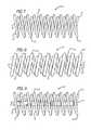
- FIG. 1is a side elevational view illustrating a preferred embodiment of the vasoocclusive coil biplex windings.
- FIG. 2is the vasoocclusive device of FIG. 1 , depicting a vasoocclusive coil having increased coil density.
- FIG. 3is the vasoocclusive device of FIG. 1 , further depicting a vasoocclusive device having an inner reinforcement stretch resistant member extending through the vasoocclusive coil biplex windings.
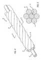
- FIG. 4is a perspective of a multi-stranded micro-cable constructed according to the invention.
- FIG. 5is a cross-section at 5 - 5 of FIG. 4 .
- FIG. 6is a cross sectional view of a vascular member with an aneurysm illustrating the approach of vasoocclusive coil biplex windings towards the aneurysm.
- FIG. 7is a side elevational view illustrating an alternate preferred embodiment of the vasoocclusive coil biplex windings with the inner reinforcement coil forming a helical winding wound in the same direction as the vasoocclusive coil winding.
- FIG. 8is the vasoocclusive device of FIG. 7 , depicting a vasoocclusive coil having increased coil density.
- FIG. 9is the vasoocclusive device of FIG. 7 , further depicting a vasoocclusive device having an inner reinforcement stretch resistant member extending through the vasoocclusive coil biplex windings.
- micro-coils formed of very small diameter wires of nickel-titanium alloy material for treatment of areas of the small diameter vasculature such as an artery or vein in the brain, for treatment of aneurysms and the like, for examplecan have relatively low yield strengths and are somewhat subject to kinking, even if made of super-elastic alloy. This can create problems during placement and if the coil is to be withdrawn after being emplaced by the doctor, as for instance, if the device is too small to effectively fill the cavity to be treated. Furthermore, even solid wires of a size suitable for use in interventional devices are not very radiopaque.
- the inventionis embodied in a micro-coil formed of at least one flexible strand of a resilient material having a helically wound coil and a second reverse helical shaped coil, or opposite wound coil, configured within the micro-coil.
- the vasoocclusive coilis formed of at least one strand of a flexible material formed to have a first helically wound coil, having a proximal and a distal end, and defining a lumen between the proximal and distal ends.
- a second helically wound coilextends through the lumen of the first coil, forming a vasoocclusive coil having biplex windings for insertion through a catheter into a desired portion of the vascular to be treated, such as an aneurysm, or other anatomical malformation of the vasculature to be treated.
- the biplex windingimproves the vasoocclusive coil mechanical properties.
- the dual helically wound coils of the biplex windingare configured to enhance the vasoocclusive coil stiffness without using large diameter wires in the primary.
- the biplex windingsprovide a reinforced coil structure that reduces coil interlocking and virtually eliminates kinking between coils.
- the vasoocclusive coil biplex windings 10preferably extend along a longitudinal axis, the inner reinforcement coil 18 being wound opposite the outer vasoocclusive coil 12 , thereby curving about the longitudinal axis to form a hollow cylindrical pattern of helical and reversed helical coil configurations.
- the biplex wound coils 10 having proximal and distal endsare fixedly attached at the proximal ends of the vasoocclusive coil 14 and inner reinforcement coil 20 .
- the first helical coil 12 and the second opposite wound coil 18may be attached by conventional methods including adhesives, solder, or heat bonding.
- the vasoocclusive coil disposed about an oppositely wound coilmay be fixedly attached at the coil distal ends 16 and 22 or at an intermediate region on the coils.
- the inner reinforcement coil 18may be wound in the same direction as the outer coil 12 , as is illustrated in FIGS. 7-9 . It is conceived that the coils of this invention may be fixedly attached at more than one region of the coil. In another presently preferred aspect, the first coil 12 and second coil 18 may not be fixedly attached. The second coil 18 may be manufactured to be securely positioned within the first coil without fixation means, thereby providing a vasoocclusive coil having greater flexibility.
- the vasoocclusive coil biplex windingsmay be formed from a variety of materials including, but not limited to, one or more strands of a metal or metal alloy such as stainless steel or a nickel-titanium alloy, which may include a radiopacity strand forming both the first coil and the second coil.
- the coilsmay include a radiopaque strand made of platinum, tungsten or gold, in order to serve as a marker.
- Other materials, such as shape memory alloysmay also be used to provide for the dual purposes of ease of insertion into a micro-catheter and formation upon deployment into the desired biplex helical configuration.
- the inner reinforcement coil and outer vasoocclusive coil of the present inventionare formed of a platinum-tungsten alloy to provide the desired vasoocclusive coil and inner reinforcement coil softness while improving other coil characteristics.
- the vasoocclusive coil and the inner reinforcement coilare formed from different materials.
- the inner reinforcement coilmay be formed of a bioactive material, such as a swelling material such as a hydrogel, polyglycolic acid or polyglycolide (PGA), or poly(D,L-lactic acid-co-glycolic acid) (PGLA), although other similar bioactive materials may also be suitable.
- a bioactive materialsuch as a swelling material such as a hydrogel, polyglycolic acid or polyglycolide (PGA), or poly(D,L-lactic acid-co-glycolic acid) (PGLA), although other similar bioactive materials may also be suitable.
- hydrogelrefers to a broad class of polymeric materials that have an affinity for water and typically swell in water, but which do not necessarily dissolve in water.
- the diameter of the wire used in the production of the coilwill be in the range of 0.0005 and 0.006 inches.
- the wire of such diameteris typically then wound into a coil having a primary diameter of between 0.005 and 0.018 inches.
- the preferable diameteris 0.010 to 0.018 inches.
- the wireshould be of sufficient diameter to provide a hoop strength to the resulting device sufficient to hold the device 10 in place within the chosen vasculature or body cavity without distending the wall of the cavity and without moving from the cavity as a result of the repetitive fluid pulsing found in the vascular system.
- the overall diameter of the device in the operable configurationis generally between 3 and 40 millimeters. Most aneurysms within the cranial vasculature can be treated by one or more devices having those diameters.
- FIG. 2depicts vasoocclusive coil biplex windings 10 wherein the outer vasoocclusive coil 12 has an increased coil diameter to provide greater contact surface area to anchor the device to the area to be treated. Varying the vasoocclusive coil diameter also impacts the degree of flexibility and stretchability for the biplex windings.
- the coil pitch of the helixthe conformity of the device to the vascular walls can be enhanced, and variation of the biplex pitch can provide a desired exposure of bioactive material in the coil, as is explained further hereinbelow.
- the characteristics of the devicesuch as loop strength and the resilience of the device are controlled by the radii of the transitions from the outer vasoocclusive coil 12 to the inner reinforcement coil 18 and the distance between the parallel loop windings.
- a variety of densitiesmay be provided in the coil to coil distance, thus assisting in the treatment of various malformations.
- the inventionis embodied in a multi-stranded micro-cable formed of a plurality of flexible strands of a resilient material with the cable including at least one radiopaque strand 30 .
- the multi-stranded micro-cable 28is approximately 0.0015 to 0.009 inches in diameter, and comprises a plurality of flexible strands 26 of nickel-titanium alloy, with at least one centrally, axially disposed radiopaque wire 30 which is approximately from 0.0005 to 0.003 inches in diameter. While the above stated diameters represent those presently known to be compatible with the invention, larger or smaller diameters may be useful for particular applications.
- the central radiopaque wire 30can be formed of platinum or gold, for example, or other similar suitable radiopaque metals, in order to provide a radiopaque marker for the deployed configuration of a device made of the cable during vascular surgery.
- the novel biplex winding 10 construction of the inventionfor use in interventional devices and the like.
- a biplex wound device made from the micro-cablebecomes virtually kink resistant compared to the single strand wires now commonly used in micro-coils.
- the multi-strand biplex cable construction of the inventionallows the micro-wires of the cable to slip across each other and reinforce each other rather than break or take a set.
- the vasoocclusive deviceis radiopaque in sizes much smaller than with other constructions.
- the micro-cable biplex construction of the inventioncan be used to produce soft, kink resistant, radiopaque stents, guidewires, guidewire distal tips, and micro-coils.
- FIG. 5is a cross-section of the micro-cable of FIG. 4 at 5 - 5 illustrating one presently preferred arrangement of the strands within the cable.
- the exterior strands 26are formed of a resilient material chosen to provide the characteristics desired for a specific application in interventional therapies.
- this materialis a platinum tungsten alloy which provides desired coil stiffness, softness, and stretchability.
- Another preferred materialis a nickel titanium super-elastic alloy which is heat treated such that the alloy is highly flexible at a temperature appropriate for introduction into the body via a catheter.
- such a cablecan have a central core 30 of a radiopaque material such as gold or platinum, thus dramatically enhancing the radiopacity of the cable.
- a radiopaque materialsuch as gold or platinum
- Even a solid super-elastic wire of the same diameter as the cablewould have substantially less radiopacity than the biplex cable of the invention with the central gold or platinum wire and the construction of the invention provides numerous other highly desirable characteristics. Among these characteristics is the relative flexibility and resistance to kinking of the cable compared to an equivalent single wire and substantially greater accommodation of the cable to bending, etc., with resultant lessening of trauma to the surrounding tissue and ease of placement in a small body cavity.
- FIG. 6illustrates a helically wound biplex coil 10 of micro-cable 28 which is formed to fit within a micro-catheter 34 for insertion into an area upon which a therapeutic procedure is to be performed. While a helical coil is illustrated, it will be appreciated that numerous other secondary shapes can be formed from the cable of the invention, as will be described further below.
- a three dimensional, essentially spherical, device(not shown) can be formed of the cable, at a temperature sufficient to heat treat the material and thereby create a memory of the desired shape.
- the deviceis then inserted into a catheter 34 from which it may be deployed into an aneurysm or the like.
- the teachings of U.S. Pat. No. 5,645,558describe the construction of such a device out of flexible wire and are incorporated by referenced herein.
- FIG. 6is an illustration of a catheter 34 using a coil 10 as a vasoocclusive device made of the present invention and used for insertion into an aneurysm 36 projecting laterally from a blood vessel 38 .
- the coil 10is contained within the outer housing of a micro-catheter 34 that is used to house the coil prior to deployment.
- the end of the catheter housing 34is introduced into the opening of the aneurysm 36 by use of a guide wire (not shown). Thereafter, the vasooclusive coil 10 , and a pusher member 32 are introduced into the catheter to provide for insertion of the vasooclusive device into the aneurysm.
- vasooclusive devicemust be withdrawn after it is frilly or partly inserted into the aneurysm. In such a case, there is a danger that the coil will be stretched beyond its elastic range or kink, or otherwise deform and make withdrawal difficult.
- vasooclusive devicesof secondary shapes which are based upon a basic configuration of a coil or the like. The present invention includes such applications within the scope of the invention. However, when vasooclusive devices made of even super-elastic material are used, it is sometimes the case that the devices will be stretched or kinked when withdrawal is attempted.
- the biplex wound cable of the present inventionsubstantially reduces the probability that kinking or stretching beyond yield will occur in a given instance, while at the same time providing radiopacity not available with other constructions.
- the present inventionrepresents an important forward step in the technology of interventional therapy.
- FIGS. 1 and 2an example of one such construction in which radiopacity is more desirable than in other forms and for that reason a number of radiopaque strands 30 may be formed into the cable both along the vasoocclusive coil 12 and the inner reinforcement coil 18 of the biplex windings. It will also be appreciated that a larger or smaller number of strands may be incorporated into a given cable and the biplex cables may be formed of multiple cables in order to provide desired bending and strength characteristics.
- the inventionis adaptable to the use of a variety of materials which by themselves would not have been easily adaptable to micro devices for interventional therapies.
- materialssuch as copper are useful for intrauterine devices and the like, but copper wire, even when heavily alloyed, has certain limitations for use in such devices.
- composite cables incorporating one or more strands of a desired materialcan be configured with other strands providing strength, flexibility, shape memory, super-elasticity, radiopacity or the like for previously unavailable characteristics in micro devices.
- the inventionis also adaptable to numerous other purposes, a further preferred embodiment in which radiopaque strands and resilient strands form a portion of the cable 10 and a therapeutic agent is contained in one of the strands.
- a therapeutic agentcan include human growth hormone, hydrogels, or a variety of other agents which will serve to provide desired therapeutic capabilities when placed within a specific area of the body being treated by use of the micro-catheter.
- the agent strandmay be placed in any of a variety of positions with the cable, from core wire outward. Also, it may be desirable to coat one or more strands with a therapeutic material for certain purposes.
- At least one of the strands in the core or exterior strandscan comprise a therapeutic agent, such as a copper or copper alloy wire or any of a variety of therapeutically active metals, alloys or components, a fiber such as Dacron (polyester), polyglycolic acid, polylactic acid, fluoropolymers, nylon, polyaramid fiber (e.g. Kevlar®), or silk chosen for thrombogenicity. Since the micro-cable consists of stranded parts, one or more strands may be longer than others, or even intermittently terminated, to thereby extend beyond the diameter of the remaining strands and thereby increase the therapeutic effect of that strand.
- a therapeutic agentsuch as a copper or copper alloy wire or any of a variety of therapeutically active metals, alloys or components
- a fibersuch as Dacron (polyester), polyglycolic acid, polylactic acid, fluoropolymers, nylon, polyaramid fiber (e.g. Kevlar®), or silk chosen for thrombo
- At least one of the strandscan be coated with or impregnated with a therapeutic material, which can include, but is not limited to, any one or combination of human growth hormone, genetic material, antigens, hydrogels, collagen, bio-absorbable polymers such as lactic acids/glycolic acids, caprolactam or microcellular foam.
- a therapeutic materialcan include, but is not limited to, any one or combination of human growth hormone, genetic material, antigens, hydrogels, collagen, bio-absorbable polymers such as lactic acids/glycolic acids, caprolactam or microcellular foam.
- one or more of the strands of the micro-cableis longer than the others, and perhaps intermittently terminated, to thereby produce a micro-cable in which the therapeutic strands extend to a greater diameter than the other strands to thus increase the therapeutic effect of the therapeutic stand.
- Such a constructionis particularly advantageous if increased thrombogenicity is desired, while maintaining structural continuity and radiopacity for the micro-cable.
- FIG. 3 and FIG. 9another presently preferred embodiment provides a vasoocclusive device having biplex windings 10 and being further reinforced by an inner stretch resistant member 42 that extends through the lumen of the vasoocclusive coil, and therein being fixedly attached at one end of at or near a distal end of the vasoocclusive biplex coil 10 .
- Attachment of the inner stretch reinforcement member 42may also allow the coil to be pushed even when such a coil is partially deployed, to improve safety during retraction of the coil.
- the vasoocclusive coil 12may be coated with one or more therapeutic agents, which may include a hydrogel.
- the inner stretch resistant member 42may be formed of a therapeutic non-metallic material to provide further therapeutic properties to the vasoocclusive biplex coils.
- the inner stretch resistant member 42may extend non-helically through the lumen of the vasoocclusive coil 18 and externally of the inner reinforcement coil 18 .
- the vasoocclusive devicemay further include an inner strand of bioactive material disposed in the center of the inner reinforcement coil 18 .
- an inner strand 44 of bioactive materialmay be inserted through the center of the inner coil to further enhance the mechanical characteristics of the coil assembly, improve stretch resistance and provide other benefits to the operation of the coil.
- the inner reinforcement stretch resistant member 42 and the inner strand of bioactive material 44may be formed from a therapeutic and/or bioactive non-metallic fiber material, such as silk, collagen, elastin or other connecting proteins, polyglycolic acid or polyglycolide (PGA), polylactic acid or poly(D,L-lactide) (PLA), poly(D,L-lactic acid-co-glycolic acid) (PGLA) or poly(D, L-lactide-co-glycolide) (PLA/PGA), poly(L-lactide) (PLLA), poly(L-lactide-co-D,L-lactide) (PLLA/PLA), poly(L-lactide-co-glycolide) (PLLA/PGA), poly(glycolide-co-trimethylene carbonate) (PGA/PTMC), polyethylene oxide (PEO), polydioxanone (PDS), polycaprolactone (PCL), hylauric acid, polyhydroxylbutyrate (PHBT), poly
- the therapeutic and/or bioactive non-metallic fiber materialmay be bioabsorbable, such as PGA, for example, or non-absorbable, such as polypropylene, for example.
- the therapeutic and/or bioactive non-metallic fiber materialmay also be used for absorbing and releasing one or more therapeutic agents.
- the inner reinforcement stretch resistant member 42can be used to enhance radiopacity, aid in secondary shape configurations, and can be configured to aid desired stiffness of the coil, and can allow a softer coil to be used without stretching of the coil.
- the inner reinforcement stretch resistant member 42may be formed from a metal or metal alloy, which may be a radiopaque metal, such as platinum, for example, and may be coated with or formed of a therapeutic or bioactive material as described above.
- the inner reinforcement stretch resistant membermay be formed as a ribbon, wire, braid, a coil, such as a primary wind, or a stranded material. It is conceivable that the inner stretch resistant member, the vasoocclusive coil and the inner reinforcement coil are all formed from a platinum tungsten alloy.
Landscapes
- Health & Medical Sciences (AREA)
- Surgery (AREA)
- Life Sciences & Earth Sciences (AREA)
- Biomedical Technology (AREA)
- Medical Informatics (AREA)
- Veterinary Medicine (AREA)
- Public Health (AREA)
- Engineering & Computer Science (AREA)
- General Health & Medical Sciences (AREA)
- Heart & Thoracic Surgery (AREA)
- Nuclear Medicine, Radiotherapy & Molecular Imaging (AREA)
- Molecular Biology (AREA)
- Animal Behavior & Ethology (AREA)
- Reproductive Health (AREA)
- Vascular Medicine (AREA)
- Neurosurgery (AREA)
- Surgical Instruments (AREA)
Abstract
Description
Claims (20)
Priority Applications (2)
| Application Number | Priority Date | Filing Date | Title |
|---|---|---|---|
| US10/960,635US8535345B2 (en) | 2004-10-07 | 2004-10-07 | Vasoocclusive coil with biplex windings to improve mechanical properties |
| US13/973,750US8888806B2 (en) | 2004-10-07 | 2013-08-22 | Vasoocclusive coil with biplex windings to improve mechanical properties |
Applications Claiming Priority (1)
| Application Number | Priority Date | Filing Date | Title |
|---|---|---|---|
| US10/960,635US8535345B2 (en) | 2004-10-07 | 2004-10-07 | Vasoocclusive coil with biplex windings to improve mechanical properties |
Related Child Applications (1)
| Application Number | Title | Priority Date | Filing Date |
|---|---|---|---|
| US13/973,750ContinuationUS8888806B2 (en) | 2004-10-07 | 2013-08-22 | Vasoocclusive coil with biplex windings to improve mechanical properties |
Publications (2)
| Publication Number | Publication Date |
|---|---|
| US20060079926A1 US20060079926A1 (en) | 2006-04-13 |
| US8535345B2true US8535345B2 (en) | 2013-09-17 |
Family
ID=36146375
Family Applications (2)
| Application Number | Title | Priority Date | Filing Date |
|---|---|---|---|
| US10/960,635Expired - Fee RelatedUS8535345B2 (en) | 2004-10-07 | 2004-10-07 | Vasoocclusive coil with biplex windings to improve mechanical properties |
| US13/973,750Expired - Fee RelatedUS8888806B2 (en) | 2004-10-07 | 2013-08-22 | Vasoocclusive coil with biplex windings to improve mechanical properties |
Family Applications After (1)
| Application Number | Title | Priority Date | Filing Date |
|---|---|---|---|
| US13/973,750Expired - Fee RelatedUS8888806B2 (en) | 2004-10-07 | 2013-08-22 | Vasoocclusive coil with biplex windings to improve mechanical properties |
Country Status (1)
| Country | Link |
|---|---|
| US (2) | US8535345B2 (en) |
Cited By (15)
| Publication number | Priority date | Publication date | Assignee | Title |
|---|---|---|---|---|
| US20130261659A1 (en)* | 2012-03-30 | 2013-10-03 | Micrus Endovascular Llc | Embolic coil detachment mechanism with flexible distal member and coupling union |
| US9636118B2 (en) | 2014-02-27 | 2017-05-02 | Incumedx, Inc. | Embolic framing microcoils |
| US20180071491A1 (en)* | 2014-10-20 | 2018-03-15 | Medtronic Cryocath Lp | Centering coiled guide |
| US10034739B2 (en) | 2012-06-18 | 2018-07-31 | Board Of Regents Of The University Of Nebraska | Stent to assist in arteriovenous fistula formation |
| US10433847B2 (en) | 2013-12-17 | 2019-10-08 | The Board Of Regents Of The University Of Nebraska | Platform device and method of use to assist in anastomosis formation |
| US10857012B2 (en) | 2015-01-20 | 2020-12-08 | Neurogami Medical, Inc. | Vascular implant |
| US10905432B2 (en)* | 2018-08-22 | 2021-02-02 | Covidien Lp | Aneurysm treatment coils and associated systems and methods of use |
| US10912569B2 (en)* | 2018-08-22 | 2021-02-09 | Covidien Lp | Aneurysm treatment coils and associated systems and methods of use |
| US10925611B2 (en) | 2015-01-20 | 2021-02-23 | Neurogami Medical, Inc. | Packaging for surgical implant |
| US10932933B2 (en) | 2016-07-29 | 2021-03-02 | Shanghai Wallaby Medical Technologies Co., Inc. | Implant delivery systems and methods |
| US11006940B2 (en) | 2015-01-20 | 2021-05-18 | Neurogami Medical, Inc. | Micrograft for the treatment of intracranial aneurysms and method for use |
| US20220096199A1 (en)* | 2020-09-29 | 2022-03-31 | Nippon Piston Ring Co., Ltd. | Medical Marker |
| US11484319B2 (en) | 2015-01-20 | 2022-11-01 | Neurogami Medical, Inc. | Delivery system for micrograft for treating intracranial aneurysms |
| US11779452B2 (en) | 2015-01-20 | 2023-10-10 | Neurogami Medical, Inc. | Vascular implant |
| US12053403B2 (en) | 2018-07-12 | 2024-08-06 | Shanghai Wallaby Medical Technologies Co., Inc. | Implant delivery system and method of use |
Families Citing this family (56)
| Publication number | Priority date | Publication date | Assignee | Title |
|---|---|---|---|---|
| US7844344B2 (en) | 2004-03-30 | 2010-11-30 | Medtronic, Inc. | MRI-safe implantable lead |
| US7704267B2 (en)* | 2004-08-04 | 2010-04-27 | C. R. Bard, Inc. | Non-entangling vena cava filter |
| ATE448737T1 (en) | 2004-09-22 | 2009-12-15 | Dendron Gmbh | DEVICE FOR IMPLANTING MICROWL COILS |
| DE502004008712D1 (en) | 2004-09-22 | 2009-01-29 | Dendron Gmbh | MEDICAL IMPLANT |
| US8425550B2 (en)* | 2004-12-01 | 2013-04-23 | Boston Scientific Scimed, Inc. | Embolic coils |
| DE102005019782A1 (en)* | 2005-04-28 | 2006-11-09 | Dendron Gmbh | Device for implantation of occlusion coils with internal securing means |
| US7789915B2 (en)* | 2005-08-31 | 2010-09-07 | Vance Products Incorporated | Stent for implantation |
| JP5230602B2 (en) | 2006-04-17 | 2013-07-10 | タイコ ヘルスケア グループ リミテッド パートナーシップ | System and method for mechanically positioning an endovascular implant |
| US8777979B2 (en) | 2006-04-17 | 2014-07-15 | Covidien Lp | System and method for mechanically positioning intravascular implants |
| US7927348B2 (en)* | 2006-10-10 | 2011-04-19 | Codman & Shurtleff, Inc. | Stretch resistant coil device |
| US9044593B2 (en) | 2007-02-14 | 2015-06-02 | Medtronic, Inc. | Discontinuous conductive filler polymer-matrix composites for electromagnetic shielding |
| CA2680607C (en)* | 2007-03-13 | 2015-07-14 | Microtherapeutics, Inc. | An implant including a coil and a stretch-resistant member |
| US8801747B2 (en)* | 2007-03-13 | 2014-08-12 | Covidien Lp | Implant, a mandrel, and a method of forming an implant |
| JP5308631B2 (en)* | 2007-04-04 | 2013-10-09 | テルモ株式会社 | catheter |
| US8483842B2 (en) | 2007-04-25 | 2013-07-09 | Medtronic, Inc. | Lead or lead extension having a conductive body and conductive body contact |
| US9037263B2 (en) | 2008-03-12 | 2015-05-19 | Medtronic, Inc. | System and method for implantable medical device lead shielding |
| EP2633823B1 (en)* | 2008-04-21 | 2016-06-01 | Covidien LP | Braid-ball embolic devices and delivery systems |
| US8702746B2 (en)* | 2008-04-29 | 2014-04-22 | Cook Medical Technologies Llc | Device and method for occlusion of fluid flow through a body vessel |
| US9622751B2 (en)* | 2008-08-06 | 2017-04-18 | Boston Scientific Scimed, Inc. | Vaso-occlusive devices with textured surfaces |
| EP2413840B1 (en) | 2009-04-02 | 2016-08-17 | Endoshape, Inc. | Vascular occlusion devices |
| US10035014B2 (en)* | 2009-04-30 | 2018-07-31 | Medtronic, Inc. | Steering an implantable medical lead via a rotational coupling to a stylet |
| US9814562B2 (en) | 2009-11-09 | 2017-11-14 | Covidien Lp | Interference-relief type delivery detachment systems |
| US20110184454A1 (en)* | 2010-01-27 | 2011-07-28 | Penumbra, Inc. | Embolic implants |
| EP2574269B1 (en) | 2010-11-25 | 2016-08-31 | Olympus Corporation | Insertion portion rigidity changeable catheter with balloon |
| EP2672899A1 (en)* | 2011-02-11 | 2013-12-18 | Stryker Corporation | Vaso-occlusive device |
| US20120289994A1 (en)* | 2011-05-12 | 2012-11-15 | Boston Scientific Scimed, Inc. | Occlusion Devices and Related Methods of Use |
| WO2012161953A2 (en)* | 2011-05-23 | 2012-11-29 | Stryker Corporation | Vaso-occlusive devices with in-situ stiffening |
| US8795313B2 (en) | 2011-09-29 | 2014-08-05 | Covidien Lp | Device detachment systems with indicators |
| US8945171B2 (en) | 2011-09-29 | 2015-02-03 | Covidien Lp | Delivery system for implantable devices |
| US9579104B2 (en) | 2011-11-30 | 2017-02-28 | Covidien Lp | Positioning and detaching implants |
| US10603043B2 (en) | 2012-01-17 | 2020-03-31 | Endoshape, Inc. | Occlusion device for a vascular or biological lumen |
| US9011480B2 (en) | 2012-01-20 | 2015-04-21 | Covidien Lp | Aneurysm treatment coils |
| US9687245B2 (en) | 2012-03-23 | 2017-06-27 | Covidien Lp | Occlusive devices and methods of use |
| US9463317B2 (en) | 2012-04-19 | 2016-10-11 | Medtronic, Inc. | Paired medical lead bodies with braided conductive shields having different physical parameter values |
| US9044575B2 (en)* | 2012-10-22 | 2015-06-02 | Medtronic Adrian Luxembourg S.a.r.l. | Catheters with enhanced flexibility and associated devices, systems, and methods |
| ES2733273T3 (en) | 2012-10-22 | 2019-11-28 | Medtronic Ardian Luxembourg | Catheters with improved flexibility |
| US9498356B2 (en) | 2012-12-19 | 2016-11-22 | Cook Medical Technologies, LLC | Flexible stent and delivery system |
| US9119948B2 (en) | 2013-02-20 | 2015-09-01 | Covidien Lp | Occlusive implants for hollow anatomical structures, delivery systems, and related methods |
| CN105307596B (en)* | 2013-03-12 | 2018-04-13 | Pfm医疗有限公司 | Vaso-Occlusive Devices for Infants |
| CN105073031B (en) | 2013-03-13 | 2017-10-27 | 内形有限公司 | Continuous embolic coil and its carrying method and device |
| CN110169802B (en) | 2013-03-15 | 2022-07-08 | 柯惠有限合伙公司 | Delivery and detachment mechanism for vascular implants |
| EP2996754B1 (en) | 2013-05-18 | 2023-04-26 | Medtronic Ardian Luxembourg S.à.r.l. | Neuromodulation catheters with shafts for enhanced flexibility and control and associated devices and systems |
| US9993638B2 (en) | 2013-12-14 | 2018-06-12 | Medtronic, Inc. | Devices, systems and methods to reduce coupling of a shield and a conductor within an implantable medical lead |
| US11224437B2 (en)* | 2014-01-14 | 2022-01-18 | Penumbra, Inc. | Soft embolic implant |
| US9675361B2 (en)* | 2014-02-28 | 2017-06-13 | Cook Medical Technologies Llc | Coil occlusion device |
| US9713475B2 (en) | 2014-04-18 | 2017-07-25 | Covidien Lp | Embolic medical devices |
| EP3171931B1 (en) | 2014-07-23 | 2021-11-10 | Medtronic, Inc. | Methods of shielding implantable medical leads and implantable medical lead extensions |
| EP3191175B1 (en) | 2014-07-24 | 2022-03-02 | Medtronic, Inc. | Apparatus for shielding implantable medical leads and lead extensions |
| US9763814B2 (en) | 2014-10-24 | 2017-09-19 | Cook Medical Technologies Llc | Elongate medical device |
| EP3266389A4 (en)* | 2015-03-03 | 2018-11-21 | Kaneka Medix Corporation | Vascular embolization tool and production method therefor |
| JP6536117B2 (en)* | 2015-03-26 | 2019-07-03 | 株式会社カネカ | In-vivo indwelling member and method of manufacturing the same |
| CN108472042B (en)* | 2015-12-18 | 2021-03-16 | 斯瑞克公司 | Vascular occlusion devices and delivery assemblies |
| US12178439B2 (en)* | 2019-11-11 | 2024-12-31 | Stryker Corporation | Embolic devices for occluding body lumens |
| CN112656476A (en)* | 2020-12-31 | 2021-04-16 | 微创神通医疗科技(上海)有限公司 | Embolism material and preparation method thereof |
| CN114176697B (en)* | 2021-12-20 | 2024-07-05 | 神遁医疗科技(上海)有限公司 | Embolic material and preparation method thereof |
| CN118633988A (en)* | 2024-06-06 | 2024-09-13 | 北京昕科医疗科技有限公司 | An embolic coil device |
Citations (119)
| Publication number | Priority date | Publication date | Assignee | Title |
|---|---|---|---|---|
| US1341052A (en) | 1916-06-15 | 1920-05-25 | Francis G Gale | Chain |
| US1667730A (en) | 1928-05-01 | of chicago | ||
| US2078182A (en) | 1935-08-09 | 1937-04-20 | Sirian Wire And Contact Compan | Tungsten manufacture |
| US2549335A (en) | 1947-04-18 | 1951-04-17 | Rahthus Max | Ornamental chain |
| US3334629A (en) | 1964-11-09 | 1967-08-08 | Bertram D Cohn | Occlusive device for inferior vena cava |
| US3649224A (en) | 1968-04-18 | 1972-03-14 | Sylvania Electric Prod | Method of making nonsag filaments for electric lamps |
| US3868956A (en) | 1972-06-05 | 1975-03-04 | Ralph J Alfidi | Vessel implantable appliance and method of implanting it |
| GB2066839B (en) | 1979-12-29 | 1984-03-14 | Vysoka Skola Chem Tech | Method of manufacture of perfumed detergents |
| US4494531A (en) | 1982-12-06 | 1985-01-22 | Cook, Incorporated | Expandable blood clot filter |
| US4512338A (en) | 1983-01-25 | 1985-04-23 | Balko Alexander B | Process for restoring patency to body vessels |
| US4531933A (en) | 1982-12-07 | 1985-07-30 | C. R. Bard, Inc. | Helical ureteral stent |
| EP0183372A1 (en) | 1984-10-19 | 1986-06-04 | RAYCHEM CORPORATION (a Delaware corporation) | Prosthetic stent |
| US4638803A (en) | 1982-09-30 | 1987-01-27 | Rand Robert W | Medical apparatus for inducing scar tissue formation in a body |
| US4655771A (en) | 1982-04-30 | 1987-04-07 | Shepherd Patents S.A. | Prosthesis comprising an expansible or contractile tubular body |
| US4718907A (en) | 1985-06-20 | 1988-01-12 | Atrium Medical Corporation | Vascular prosthesis having fluorinated coating with varying F/C ratio |
| US4748986A (en) | 1985-11-26 | 1988-06-07 | Advanced Cardiovascular Systems, Inc. | Floppy guide wire with opaque tip |
| US4768507A (en) | 1986-02-24 | 1988-09-06 | Medinnovations, Inc. | Intravascular stent and percutaneous insertion catheter system for the dilation of an arterial stenosis and the prevention of arterial restenosis |
| US4795458A (en) | 1987-07-02 | 1989-01-03 | Regan Barrie F | Stent for use following balloon angioplasty |
| US4800882A (en) | 1987-03-13 | 1989-01-31 | Cook Incorporated | Endovascular stent and delivery system |
| US4813925A (en) | 1987-04-21 | 1989-03-21 | Medical Engineering Corporation | Spiral ureteral stent |
| US4820298A (en) | 1987-11-20 | 1989-04-11 | Leveen Eric G | Internal vascular prosthesis |
| US4830003A (en) | 1988-06-17 | 1989-05-16 | Wolff Rodney G | Compressive stent and delivery system |
| US4832055A (en) | 1988-07-08 | 1989-05-23 | Palestrant Aubrey M | Mechanically locking blood clot filter |
| US4850960A (en) | 1987-07-08 | 1989-07-25 | Joseph Grayzel | Diagonally tapered, bevelled tip introducing catheter and sheath and method for insertion |
| US4856516A (en) | 1989-01-09 | 1989-08-15 | Cordis Corporation | Endovascular stent apparatus and method |
| EP0382014A1 (en) | 1989-01-26 | 1990-08-16 | Advanced Cardiovascular Systems, Inc. | Intravascular endoprothesis |
| US4957479A (en) | 1988-10-17 | 1990-09-18 | Vance Products Incorporated | Indwelling ureteral stent placement apparatus |
| US4957501A (en) | 1987-12-31 | 1990-09-18 | Biomat, S.A.R.L. | Anti-embolic filter |
| US4990155A (en) | 1989-05-19 | 1991-02-05 | Wilkoff Howard M | Surgical stent method and apparatus |
| US4994069A (en) | 1988-11-02 | 1991-02-19 | Target Therapeutics | Vaso-occlusion coil and method |
| US5026377A (en) | 1989-07-13 | 1991-06-25 | American Medical Systems, Inc. | Stent placement instrument and method |
| US5041084A (en) | 1990-08-09 | 1991-08-20 | Dlp, Inc. | Single stage venous catheter |
| US5064435A (en) | 1990-06-28 | 1991-11-12 | Schneider (Usa) Inc. | Self-expanding prosthesis having stable axial length |
| US5071407A (en) | 1990-04-12 | 1991-12-10 | Schneider (U.S.A.) Inc. | Radially expandable fixation member |
| US5104404A (en) | 1989-10-02 | 1992-04-14 | Medtronic, Inc. | Articulated stent |
| US5108407A (en) | 1990-06-08 | 1992-04-28 | Rush-Presbyterian St. Luke's Medical Center | Method and apparatus for placement of an embolic coil |
| US5122136A (en) | 1990-03-13 | 1992-06-16 | The Regents Of The University Of California | Endovascular electrolytically detachable guidewire tip for the electroformation of thrombus in arteries, veins, aneurysms, vascular malformations and arteriovenous fistulas |
| US5133732A (en) | 1987-10-19 | 1992-07-28 | Medtronic, Inc. | Intravascular stent |
| US5133731A (en) | 1990-11-09 | 1992-07-28 | Catheter Research, Inc. | Embolus supply system and method |
| US5141502A (en) | 1991-08-28 | 1992-08-25 | Macaluso Jr Joseph N | Ureteral stent |
| US5147370A (en) | 1991-06-12 | 1992-09-15 | Mcnamara Thomas O | Nitinol stent for hollow body conduits |
| US5151105A (en) | 1991-10-07 | 1992-09-29 | Kwan Gett Clifford | Collapsible vessel sleeve implant |
| US5154705A (en)* | 1987-09-30 | 1992-10-13 | Lake Region Manufacturing Co., Inc. | Hollow lumen cable apparatus |
| US5160341A (en) | 1990-11-08 | 1992-11-03 | Advanced Surgical Intervention, Inc. | Resorbable urethral stent and apparatus for its insertion |
| US5176625A (en) | 1990-10-25 | 1993-01-05 | Brisson A Glen | Stent for ureter |
| US5176661A (en) | 1988-09-06 | 1993-01-05 | Advanced Cardiovascular Systems, Inc. | Composite vascular catheter |
| US5183085A (en) | 1991-09-27 | 1993-02-02 | Hans Timmermans | Method and apparatus for compressing a stent prior to insertion |
| US5186992A (en) | 1990-03-12 | 1993-02-16 | The Bentley-Harris Manufacturing Company | Braided product and method of making same |
| US5203772A (en) | 1989-01-09 | 1993-04-20 | Pilot Cardiovascular Systems, Inc. | Steerable medical device |
| US5217484A (en) | 1991-06-07 | 1993-06-08 | Marks Michael P | Retractable-wire catheter device and method |
| US5222969A (en) | 1992-03-16 | 1993-06-29 | Rolando Gillis | Intravascular stent for cardiovascular intervention |
| US5226911A (en) | 1991-10-02 | 1993-07-13 | Target Therapeutics | Vasoocclusion coil with attached fibrous element(s) |
| US5228453A (en) | 1991-05-07 | 1993-07-20 | Target Therapeutics, Inc. | Catheter guide wire |
| US5234456A (en) | 1990-02-08 | 1993-08-10 | Pfizer Hospital Products Group, Inc. | Hydrophilic stent |
| US5250071A (en) | 1992-09-22 | 1993-10-05 | Target Therapeutics, Inc. | Detachable embolic coil assembly using interlocking clasps and method of use |
| US5261916A (en) | 1991-12-12 | 1993-11-16 | Target Therapeutics | Detachable pusher-vasoocclusive coil assembly with interlocking ball and keyway coupling |
| US5304194A (en) | 1991-10-02 | 1994-04-19 | Target Therapeutics | Vasoocclusion coil with attached fibrous element(s) |
| US5304195A (en) | 1991-12-12 | 1994-04-19 | Target Therapeutics, Inc. | Detachable pusher-vasoocclusive coil assembly with interlocking coupling |
| US5312415A (en) | 1992-09-22 | 1994-05-17 | Target Therapeutics, Inc. | Assembly for placement of embolic coils using frictional placement |
| US5314472A (en) | 1991-10-01 | 1994-05-24 | Cook Incorporated | Vascular stent |
| US5334210A (en) | 1993-04-09 | 1994-08-02 | Cook Incorporated | Vascular occlusion assembly |
| US5336205A (en) | 1993-02-25 | 1994-08-09 | Target Therapeutics, Inc. | Flow directed catheter |
| US5342387A (en) | 1992-06-18 | 1994-08-30 | American Biomed, Inc. | Artificial support for a blood vessel |
| US5345945A (en)* | 1990-08-29 | 1994-09-13 | Baxter International Inc. | Dual coil guidewire with radiopaque distal tip |
| US5350398A (en) | 1991-05-13 | 1994-09-27 | Dusan Pavcnik | Self-expanding filter for percutaneous insertion |
| US5350397A (en) | 1992-11-13 | 1994-09-27 | Target Therapeutics, Inc. | Axially detachable embolic coil assembly |
| US5354295A (en) | 1990-03-13 | 1994-10-11 | Target Therapeutics, Inc. | In an endovascular electrolytically detachable wire and tip for the formation of thrombus in arteries, veins, aneurysms, vascular malformations and arteriovenous fistulas |
| US5370683A (en) | 1992-03-25 | 1994-12-06 | Cook Incorporated | Vascular stent |
| US5382259A (en) | 1992-10-26 | 1995-01-17 | Target Therapeutics, Inc. | Vasoocclusion coil with attached tubular woven or braided fibrous covering |
| US5423829A (en) | 1993-11-03 | 1995-06-13 | Target Therapeutics, Inc. | Electrolytically severable joint for endovascular embolic devices |
| US5441516A (en) | 1994-03-03 | 1995-08-15 | Scimed Lifesystems Inc. | Temporary stent |
| US5443478A (en) | 1992-09-02 | 1995-08-22 | Board Of Regents, The University Of Texas System | Multi-element intravascular occlusion device |
| US5514176A (en) | 1995-01-20 | 1996-05-07 | Vance Products Inc. | Pull apart coil stent |
| US5522836A (en) | 1994-06-27 | 1996-06-04 | Target Therapeutics, Inc. | Electrolytically severable coil assembly with movable detachment point |
| US5527354A (en) | 1991-06-28 | 1996-06-18 | Cook Incorporated | Stent formed of half-round wire |
| US5536274A (en) | 1991-02-15 | 1996-07-16 | pfm Produkterfur Die Medizin | Spiral implant for organ pathways |
| US5549624A (en) | 1994-06-24 | 1996-08-27 | Target Therapeutics, Inc. | Fibered vasooclusion coils |
| US5562698A (en) | 1994-03-09 | 1996-10-08 | Cook Incorporated | Intravascular treatment system |
| US5562641A (en) | 1993-05-28 | 1996-10-08 | A Bromberg & Co. Ltd. | Two way shape memory alloy medical stent |
| US5569245A (en) | 1990-03-13 | 1996-10-29 | The Regents Of The University Of California | Detachable endovascular occlusion device activated by alternating electric current |
| US5582619A (en) | 1995-06-30 | 1996-12-10 | Target Therapeutics, Inc. | Stretch resistant vaso-occlusive coils |
| EP0747014A1 (en) | 1995-06-06 | 1996-12-11 | Target Therapeutics, Inc. | Multiple layered vaso-occlusive coils |
| EP0747013A1 (en) | 1995-06-06 | 1996-12-11 | Target Therapeutics | Three dimensional in-filling vaso-occlusive coils |
| EP0743047A3 (en) | 1995-04-20 | 1997-03-26 | Univ South Carolina | Anatomically shaped vaso-occlusion device and its manufacturing process |
| EP0765636A2 (en) | 1995-09-29 | 1997-04-02 | Target Therapeutics, Inc. | Anatomically shaped Vasoocclusive devices |
| US5624449A (en) | 1993-11-03 | 1997-04-29 | Target Therapeutics | Electrolytically severable joint for endovascular embolic devices |
| US5637113A (en) | 1994-12-13 | 1997-06-10 | Advanced Cardiovascular Systems, Inc. | Polymer film for wrapping a stent structure |
| US5639277A (en) | 1995-04-28 | 1997-06-17 | Target Therapeutics, Inc. | Embolic coils with offset helical and twisted helical shapes |
| US5643254A (en) | 1994-03-03 | 1997-07-01 | Target Therapeutics, Inc. | Endovascular embolic device detachment detection method |
| US5645082A (en) | 1993-01-29 | 1997-07-08 | Cardima, Inc. | Intravascular method and system for treating arrhythmia |
| US5649949A (en) | 1996-03-14 | 1997-07-22 | Target Therapeutics, Inc. | Variable cross-section conical vasoocclusive coils |
| US5667522A (en) | 1994-03-03 | 1997-09-16 | Medinol Ltd. | Urological stent and deployment device therefor |
| US5669931A (en) | 1995-03-30 | 1997-09-23 | Target Therapeutics, Inc. | Liquid coils with secondary shape |
| US5676697A (en) | 1996-07-29 | 1997-10-14 | Cardiovascular Dynamics, Inc. | Two-piece, bifurcated intraluminal graft for repair of aneurysm |
| US5690666A (en) | 1992-11-18 | 1997-11-25 | Target Therapeutics, Inc. | Ultrasoft embolism coils and process for using them |
| US5690643A (en) | 1996-02-20 | 1997-11-25 | Leocor, Incorporated | Stent delivery system |
| US5690671A (en) | 1994-12-13 | 1997-11-25 | Micro Interventional Systems, Inc. | Embolic elements and methods and apparatus for their delivery |
| US5707389A (en) | 1995-06-07 | 1998-01-13 | Baxter International Inc. | Side branch occlusion catheter device having integrated endoscope for performing endoscopically visualized occlusion of the side branches of an anatomical passageway |
| EP0820726A2 (en) | 1996-07-26 | 1998-01-28 | Target Therapeutics, Inc. | Aneurysm closure device assembly |
| US5725552A (en) | 1994-07-08 | 1998-03-10 | Aga Medical Corporation | Percutaneous catheter directed intravascular occlusion devices |
| US5725546A (en) | 1994-06-24 | 1998-03-10 | Target Therapeutics, Inc. | Detachable microcoil delivery catheter |
| US5733329A (en) | 1996-12-30 | 1998-03-31 | Target Therapeutics, Inc. | Vaso-occlusive coil with conical end |
| US5749894A (en) | 1996-01-18 | 1998-05-12 | Target Therapeutics, Inc. | Aneurysm closure method |
| US5766160A (en) | 1995-06-06 | 1998-06-16 | Target Therapeutics, Inc. | Variable stiffness coils |
| US5843118A (en) | 1995-12-04 | 1998-12-01 | Target Therapeutics, Inc. | Fibered micro vaso-occlusive devices |
| US5976162A (en)* | 1996-04-10 | 1999-11-02 | Target Therapeutics, Inc. | Soft-ended fibered micro vaso-occlusive devices |
| US6063111A (en)* | 1998-03-31 | 2000-05-16 | Cordis Corporation | Stent aneurysm treatment system and method |
| US6168570B1 (en)* | 1997-12-05 | 2001-01-02 | Micrus Corporation | Micro-strand cable with enhanced radiopacity |
| US6171326B1 (en) | 1998-08-27 | 2001-01-09 | Micrus Corporation | Three dimensional, low friction vasoocclusive coil, and method of manufacture |
| US6193728B1 (en)* | 1995-06-30 | 2001-02-27 | Target Therapeutics, Inc. | Stretch resistant vaso-occlusive coils (II) |
| US20020002382A1 (en)* | 1999-06-04 | 2002-01-03 | Wallace Michael P. | Polymer covered vaso-occlusive devices and methods of producing such devices |
| US6602261B2 (en) | 1999-10-04 | 2003-08-05 | Microvention, Inc. | Filamentous embolic device with expansile elements |
| US20040006363A1 (en)* | 2002-07-02 | 2004-01-08 | Dean Schaefer | Coaxial stretch-resistant vaso-occlusive device |
| US20040034363A1 (en)* | 2002-07-23 | 2004-02-19 | Peter Wilson | Stretch resistant therapeutic device |
| US20040138695A1 (en)* | 2002-06-18 | 2004-07-15 | Shu-Tung Li | Coatings of implants |
| US6833003B2 (en)* | 2002-06-24 | 2004-12-21 | Cordis Neurovascular | Expandable stent and delivery system |
| US20050171572A1 (en)* | 2002-07-31 | 2005-08-04 | Microvention, Inc. | Multi-layer coaxial vaso-occlusive device |
| US20060036281A1 (en)* | 2004-05-21 | 2006-02-16 | Micro Therapeutics, Inc. | Metallic coils enlaced with biological or biodegradable or synthetic polymers or fibers for embolization of a body cavity |
| US7166122B2 (en)* | 2002-06-27 | 2007-01-23 | Boston Scientific Scimed, Inc. | Anchor assemblies in stretch-resistant vaso-occlusive coils |
Family Cites Families (6)
| Publication number | Priority date | Publication date | Assignee | Title |
|---|---|---|---|---|
| GB1075325A (en)* | 1965-02-16 | 1967-07-12 | Joh Mustad Ab | An electrophonic musical instrument |
| US5222822A (en)* | 1991-12-27 | 1993-06-29 | Javier Hernandez | Dispensing device for particulate material |
| US5733294A (en) | 1996-02-28 | 1998-03-31 | B. Braun Medical, Inc. | Self expanding cardiovascular occlusion device, method of using and method of making the same |
| US6190402B1 (en) | 1996-06-21 | 2001-02-20 | Musc Foundation For Research Development | Insitu formable and self-forming intravascular flow modifier (IFM) and IFM assembly for deployment of same |
| DK177010B1 (en) | 1996-09-03 | 2010-11-29 | Cook William Europ | Embolization device for placement in a blood vessel |
| US6159165A (en) | 1997-12-05 | 2000-12-12 | Micrus Corporation | Three dimensional spherical micro-coils manufactured from radiopaque nickel-titanium microstrand |
- 2004
- 2004-10-07USUS10/960,635patent/US8535345B2/ennot_activeExpired - Fee Related
- 2013
- 2013-08-22USUS13/973,750patent/US8888806B2/ennot_activeExpired - Fee Related
Patent Citations (132)
| Publication number | Priority date | Publication date | Assignee | Title |
|---|---|---|---|---|
| US1667730A (en) | 1928-05-01 | of chicago | ||
| US1341052A (en) | 1916-06-15 | 1920-05-25 | Francis G Gale | Chain |
| US2078182A (en) | 1935-08-09 | 1937-04-20 | Sirian Wire And Contact Compan | Tungsten manufacture |
| US2549335A (en) | 1947-04-18 | 1951-04-17 | Rahthus Max | Ornamental chain |
| US3334629A (en) | 1964-11-09 | 1967-08-08 | Bertram D Cohn | Occlusive device for inferior vena cava |
| US3649224A (en) | 1968-04-18 | 1972-03-14 | Sylvania Electric Prod | Method of making nonsag filaments for electric lamps |
| US3868956A (en) | 1972-06-05 | 1975-03-04 | Ralph J Alfidi | Vessel implantable appliance and method of implanting it |
| GB2066839B (en) | 1979-12-29 | 1984-03-14 | Vysoka Skola Chem Tech | Method of manufacture of perfumed detergents |
| US4954126B1 (en) | 1982-04-30 | 1996-05-28 | Ams Med Invent S A | Prosthesis comprising an expansible or contractile tubular body |
| US4954126A (en) | 1982-04-30 | 1990-09-04 | Shepherd Patents S.A. | Prosthesis comprising an expansible or contractile tubular body |
| US4655771B1 (en) | 1982-04-30 | 1996-09-10 | Medinvent Ams Sa | Prosthesis comprising an expansible or contractile tubular body |
| US4655771A (en) | 1982-04-30 | 1987-04-07 | Shepherd Patents S.A. | Prosthesis comprising an expansible or contractile tubular body |
| US4638803A (en) | 1982-09-30 | 1987-01-27 | Rand Robert W | Medical apparatus for inducing scar tissue formation in a body |
| US4494531A (en) | 1982-12-06 | 1985-01-22 | Cook, Incorporated | Expandable blood clot filter |
| US4531933A (en) | 1982-12-07 | 1985-07-30 | C. R. Bard, Inc. | Helical ureteral stent |
| US4512338A (en) | 1983-01-25 | 1985-04-23 | Balko Alexander B | Process for restoring patency to body vessels |
| EP0183372A1 (en) | 1984-10-19 | 1986-06-04 | RAYCHEM CORPORATION (a Delaware corporation) | Prosthetic stent |
| US4718907A (en) | 1985-06-20 | 1988-01-12 | Atrium Medical Corporation | Vascular prosthesis having fluorinated coating with varying F/C ratio |
| US4748986A (en) | 1985-11-26 | 1988-06-07 | Advanced Cardiovascular Systems, Inc. | Floppy guide wire with opaque tip |
| US4768507A (en) | 1986-02-24 | 1988-09-06 | Medinnovations, Inc. | Intravascular stent and percutaneous insertion catheter system for the dilation of an arterial stenosis and the prevention of arterial restenosis |
| US4800882A (en) | 1987-03-13 | 1989-01-31 | Cook Incorporated | Endovascular stent and delivery system |
| US4813925A (en) | 1987-04-21 | 1989-03-21 | Medical Engineering Corporation | Spiral ureteral stent |
| US4795458A (en) | 1987-07-02 | 1989-01-03 | Regan Barrie F | Stent for use following balloon angioplasty |
| US4850960A (en) | 1987-07-08 | 1989-07-25 | Joseph Grayzel | Diagonally tapered, bevelled tip introducing catheter and sheath and method for insertion |
| US5154705A (en)* | 1987-09-30 | 1992-10-13 | Lake Region Manufacturing Co., Inc. | Hollow lumen cable apparatus |
| US5133732A (en) | 1987-10-19 | 1992-07-28 | Medtronic, Inc. | Intravascular stent |
| US4820298A (en) | 1987-11-20 | 1989-04-11 | Leveen Eric G | Internal vascular prosthesis |
| US4957501A (en) | 1987-12-31 | 1990-09-18 | Biomat, S.A.R.L. | Anti-embolic filter |
| US4830003A (en) | 1988-06-17 | 1989-05-16 | Wolff Rodney G | Compressive stent and delivery system |
| US4832055A (en) | 1988-07-08 | 1989-05-23 | Palestrant Aubrey M | Mechanically locking blood clot filter |
| US5176661A (en) | 1988-09-06 | 1993-01-05 | Advanced Cardiovascular Systems, Inc. | Composite vascular catheter |
| US4957479A (en) | 1988-10-17 | 1990-09-18 | Vance Products Incorporated | Indwelling ureteral stent placement apparatus |
| US4994069A (en) | 1988-11-02 | 1991-02-19 | Target Therapeutics | Vaso-occlusion coil and method |
| US4856516A (en) | 1989-01-09 | 1989-08-15 | Cordis Corporation | Endovascular stent apparatus and method |
| US5203772A (en) | 1989-01-09 | 1993-04-20 | Pilot Cardiovascular Systems, Inc. | Steerable medical device |
| EP0382014A1 (en) | 1989-01-26 | 1990-08-16 | Advanced Cardiovascular Systems, Inc. | Intravascular endoprothesis |
| US4990155A (en) | 1989-05-19 | 1991-02-05 | Wilkoff Howard M | Surgical stent method and apparatus |
| US5026377A (en) | 1989-07-13 | 1991-06-25 | American Medical Systems, Inc. | Stent placement instrument and method |
| US5104404A (en) | 1989-10-02 | 1992-04-14 | Medtronic, Inc. | Articulated stent |
| US5234456A (en) | 1990-02-08 | 1993-08-10 | Pfizer Hospital Products Group, Inc. | Hydrophilic stent |
| US5186992A (en) | 1990-03-12 | 1993-02-16 | The Bentley-Harris Manufacturing Company | Braided product and method of making same |
| US5122136A (en) | 1990-03-13 | 1992-06-16 | The Regents Of The University Of California | Endovascular electrolytically detachable guidewire tip for the electroformation of thrombus in arteries, veins, aneurysms, vascular malformations and arteriovenous fistulas |
| US5569245A (en) | 1990-03-13 | 1996-10-29 | The Regents Of The University Of California | Detachable endovascular occlusion device activated by alternating electric current |
| US5354295A (en) | 1990-03-13 | 1994-10-11 | Target Therapeutics, Inc. | In an endovascular electrolytically detachable wire and tip for the formation of thrombus in arteries, veins, aneurysms, vascular malformations and arteriovenous fistulas |
| US5071407A (en) | 1990-04-12 | 1991-12-10 | Schneider (U.S.A.) Inc. | Radially expandable fixation member |
| US5108407A (en) | 1990-06-08 | 1992-04-28 | Rush-Presbyterian St. Luke's Medical Center | Method and apparatus for placement of an embolic coil |
| US5064435A (en) | 1990-06-28 | 1991-11-12 | Schneider (Usa) Inc. | Self-expanding prosthesis having stable axial length |
| US5041084A (en) | 1990-08-09 | 1991-08-20 | Dlp, Inc. | Single stage venous catheter |
| US5345945A (en)* | 1990-08-29 | 1994-09-13 | Baxter International Inc. | Dual coil guidewire with radiopaque distal tip |
| US5176625A (en) | 1990-10-25 | 1993-01-05 | Brisson A Glen | Stent for ureter |
| US5160341A (en) | 1990-11-08 | 1992-11-03 | Advanced Surgical Intervention, Inc. | Resorbable urethral stent and apparatus for its insertion |
| US5133731A (en) | 1990-11-09 | 1992-07-28 | Catheter Research, Inc. | Embolus supply system and method |
| US5536274A (en) | 1991-02-15 | 1996-07-16 | pfm Produkterfur Die Medizin | Spiral implant for organ pathways |
| US5228453A (en) | 1991-05-07 | 1993-07-20 | Target Therapeutics, Inc. | Catheter guide wire |
| US5350398A (en) | 1991-05-13 | 1994-09-27 | Dusan Pavcnik | Self-expanding filter for percutaneous insertion |
| US5217484A (en) | 1991-06-07 | 1993-06-08 | Marks Michael P | Retractable-wire catheter device and method |
| US5147370A (en) | 1991-06-12 | 1992-09-15 | Mcnamara Thomas O | Nitinol stent for hollow body conduits |
| US5527354A (en) | 1991-06-28 | 1996-06-18 | Cook Incorporated | Stent formed of half-round wire |
| US5141502A (en) | 1991-08-28 | 1992-08-25 | Macaluso Jr Joseph N | Ureteral stent |
| US5183085A (en) | 1991-09-27 | 1993-02-02 | Hans Timmermans | Method and apparatus for compressing a stent prior to insertion |
| US5314472A (en) | 1991-10-01 | 1994-05-24 | Cook Incorporated | Vascular stent |
| US5304194A (en) | 1991-10-02 | 1994-04-19 | Target Therapeutics | Vasoocclusion coil with attached fibrous element(s) |
| US5226911A (en) | 1991-10-02 | 1993-07-13 | Target Therapeutics | Vasoocclusion coil with attached fibrous element(s) |
| US5151105A (en) | 1991-10-07 | 1992-09-29 | Kwan Gett Clifford | Collapsible vessel sleeve implant |
| US5261916A (en) | 1991-12-12 | 1993-11-16 | Target Therapeutics | Detachable pusher-vasoocclusive coil assembly with interlocking ball and keyway coupling |
| US5304195A (en) | 1991-12-12 | 1994-04-19 | Target Therapeutics, Inc. | Detachable pusher-vasoocclusive coil assembly with interlocking coupling |
| US5222969A (en) | 1992-03-16 | 1993-06-29 | Rolando Gillis | Intravascular stent for cardiovascular intervention |
| US5370683A (en) | 1992-03-25 | 1994-12-06 | Cook Incorporated | Vascular stent |
| US5607445A (en) | 1992-06-18 | 1997-03-04 | American Biomed, Inc. | Stent for supporting a blood vessel |
| US5342387A (en) | 1992-06-18 | 1994-08-30 | American Biomed, Inc. | Artificial support for a blood vessel |
| US5443478A (en) | 1992-09-02 | 1995-08-22 | Board Of Regents, The University Of Texas System | Multi-element intravascular occlusion device |
| US5250071A (en) | 1992-09-22 | 1993-10-05 | Target Therapeutics, Inc. | Detachable embolic coil assembly using interlocking clasps and method of use |
| US5312415A (en) | 1992-09-22 | 1994-05-17 | Target Therapeutics, Inc. | Assembly for placement of embolic coils using frictional placement |
| US5382259A (en) | 1992-10-26 | 1995-01-17 | Target Therapeutics, Inc. | Vasoocclusion coil with attached tubular woven or braided fibrous covering |
| US5522822A (en) | 1992-10-26 | 1996-06-04 | Target Therapeutics, Inc. | Vasoocclusion coil with attached tubular woven or braided fibrous covering |
| US5350397A (en) | 1992-11-13 | 1994-09-27 | Target Therapeutics, Inc. | Axially detachable embolic coil assembly |
| US5718711A (en) | 1992-11-18 | 1998-02-17 | Target Therapeutics, Inc. | Ultrasoft embolism devices and process for using them |
| US5690666A (en) | 1992-11-18 | 1997-11-25 | Target Therapeutics, Inc. | Ultrasoft embolism coils and process for using them |
| US5685322A (en) | 1993-01-29 | 1997-11-11 | Cardima, Inc. | Intravascular system for treating arrhythmia |
| US5645082A (en) | 1993-01-29 | 1997-07-08 | Cardima, Inc. | Intravascular method and system for treating arrhythmia |
| US5336205A (en) | 1993-02-25 | 1994-08-09 | Target Therapeutics, Inc. | Flow directed catheter |
| US5334210A (en) | 1993-04-09 | 1994-08-02 | Cook Incorporated | Vascular occlusion assembly |
| US5562641A (en) | 1993-05-28 | 1996-10-08 | A Bromberg & Co. Ltd. | Two way shape memory alloy medical stent |
| US5624449A (en) | 1993-11-03 | 1997-04-29 | Target Therapeutics | Electrolytically severable joint for endovascular embolic devices |
| US5423829A (en) | 1993-11-03 | 1995-06-13 | Target Therapeutics, Inc. | Electrolytically severable joint for endovascular embolic devices |
| US5643254A (en) | 1994-03-03 | 1997-07-01 | Target Therapeutics, Inc. | Endovascular embolic device detachment detection method |
| US5667522A (en) | 1994-03-03 | 1997-09-16 | Medinol Ltd. | Urological stent and deployment device therefor |
| US5441516A (en) | 1994-03-03 | 1995-08-15 | Scimed Lifesystems Inc. | Temporary stent |
| US5562698A (en) | 1994-03-09 | 1996-10-08 | Cook Incorporated | Intravascular treatment system |
| US5700258A (en) | 1994-06-24 | 1997-12-23 | Target Therapeutics, Inc. | Complex coils having fibered centers |
| US5549624A (en) | 1994-06-24 | 1996-08-27 | Target Therapeutics, Inc. | Fibered vasooclusion coils |
| US5725546A (en) | 1994-06-24 | 1998-03-10 | Target Therapeutics, Inc. | Detachable microcoil delivery catheter |
| US5522836A (en) | 1994-06-27 | 1996-06-04 | Target Therapeutics, Inc. | Electrolytically severable coil assembly with movable detachment point |
| US5725552A (en) | 1994-07-08 | 1998-03-10 | Aga Medical Corporation | Percutaneous catheter directed intravascular occlusion devices |
| US5637113A (en) | 1994-12-13 | 1997-06-10 | Advanced Cardiovascular Systems, Inc. | Polymer film for wrapping a stent structure |
| US5690671A (en) | 1994-12-13 | 1997-11-25 | Micro Interventional Systems, Inc. | Embolic elements and methods and apparatus for their delivery |
| US5514176A (en) | 1995-01-20 | 1996-05-07 | Vance Products Inc. | Pull apart coil stent |
| US5669931A (en) | 1995-03-30 | 1997-09-23 | Target Therapeutics, Inc. | Liquid coils with secondary shape |
| EP0743047A3 (en) | 1995-04-20 | 1997-03-26 | Univ South Carolina | Anatomically shaped vaso-occlusion device and its manufacturing process |
| US5645558A (en) | 1995-04-20 | 1997-07-08 | Medical University Of South Carolina | Anatomically shaped vasoocclusive device and method of making the same |
| US5639277A (en) | 1995-04-28 | 1997-06-17 | Target Therapeutics, Inc. | Embolic coils with offset helical and twisted helical shapes |
| US5749891A (en) | 1995-06-06 | 1998-05-12 | Target Therapeutics, Inc. | Multiple layered vaso-occlusive coils |
| US5766160A (en) | 1995-06-06 | 1998-06-16 | Target Therapeutics, Inc. | Variable stiffness coils |
| EP0747013A1 (en) | 1995-06-06 | 1996-12-11 | Target Therapeutics | Three dimensional in-filling vaso-occlusive coils |
| EP0747014A1 (en) | 1995-06-06 | 1996-12-11 | Target Therapeutics, Inc. | Multiple layered vaso-occlusive coils |
| US5624461A (en) | 1995-06-06 | 1997-04-29 | Target Therapeutics, Inc. | Three dimensional in-filling vaso-occlusive coils |
| US5707389A (en) | 1995-06-07 | 1998-01-13 | Baxter International Inc. | Side branch occlusion catheter device having integrated endoscope for performing endoscopically visualized occlusion of the side branches of an anatomical passageway |
| US6193728B1 (en)* | 1995-06-30 | 2001-02-27 | Target Therapeutics, Inc. | Stretch resistant vaso-occlusive coils (II) |
| US5582619A (en) | 1995-06-30 | 1996-12-10 | Target Therapeutics, Inc. | Stretch resistant vaso-occlusive coils |
| EP0765636A2 (en) | 1995-09-29 | 1997-04-02 | Target Therapeutics, Inc. | Anatomically shaped Vasoocclusive devices |
| US5843118A (en) | 1995-12-04 | 1998-12-01 | Target Therapeutics, Inc. | Fibered micro vaso-occlusive devices |
| US5749894A (en) | 1996-01-18 | 1998-05-12 | Target Therapeutics, Inc. | Aneurysm closure method |
| US5690643A (en) | 1996-02-20 | 1997-11-25 | Leocor, Incorporated | Stent delivery system |
| US5649949A (en) | 1996-03-14 | 1997-07-22 | Target Therapeutics, Inc. | Variable cross-section conical vasoocclusive coils |
| US5976162A (en)* | 1996-04-10 | 1999-11-02 | Target Therapeutics, Inc. | Soft-ended fibered micro vaso-occlusive devices |
| EP0820726A2 (en) | 1996-07-26 | 1998-01-28 | Target Therapeutics, Inc. | Aneurysm closure device assembly |
| US5676697A (en) | 1996-07-29 | 1997-10-14 | Cardiovascular Dynamics, Inc. | Two-piece, bifurcated intraluminal graft for repair of aneurysm |
| US5733329A (en) | 1996-12-30 | 1998-03-31 | Target Therapeutics, Inc. | Vaso-occlusive coil with conical end |
| US6168570B1 (en)* | 1997-12-05 | 2001-01-02 | Micrus Corporation | Micro-strand cable with enhanced radiopacity |
| US6063111A (en)* | 1998-03-31 | 2000-05-16 | Cordis Corporation | Stent aneurysm treatment system and method |
| US6361558B1 (en)* | 1998-03-31 | 2002-03-26 | Cordis Neurovascular, Inc. | Stent aneurysm treatment system and method |
| US6171326B1 (en) | 1998-08-27 | 2001-01-09 | Micrus Corporation | Three dimensional, low friction vasoocclusive coil, and method of manufacture |
| US20020002382A1 (en)* | 1999-06-04 | 2002-01-03 | Wallace Michael P. | Polymer covered vaso-occlusive devices and methods of producing such devices |
| US6602261B2 (en) | 1999-10-04 | 2003-08-05 | Microvention, Inc. | Filamentous embolic device with expansile elements |
| US20040138695A1 (en)* | 2002-06-18 | 2004-07-15 | Shu-Tung Li | Coatings of implants |
| US6833003B2 (en)* | 2002-06-24 | 2004-12-21 | Cordis Neurovascular | Expandable stent and delivery system |
| US7166122B2 (en)* | 2002-06-27 | 2007-01-23 | Boston Scientific Scimed, Inc. | Anchor assemblies in stretch-resistant vaso-occlusive coils |
| US20040006363A1 (en)* | 2002-07-02 | 2004-01-08 | Dean Schaefer | Coaxial stretch-resistant vaso-occlusive device |
| US20040006354A1 (en)* | 2002-07-02 | 2004-01-08 | Dean Schaefer | Coaxial stretch-resistant vaso-occlusive device |
| US20040034363A1 (en)* | 2002-07-23 | 2004-02-19 | Peter Wilson | Stretch resistant therapeutic device |
| US20050171572A1 (en)* | 2002-07-31 | 2005-08-04 | Microvention, Inc. | Multi-layer coaxial vaso-occlusive device |
| US20060036281A1 (en)* | 2004-05-21 | 2006-02-16 | Micro Therapeutics, Inc. | Metallic coils enlaced with biological or biodegradable or synthetic polymers or fibers for embolization of a body cavity |
Non-Patent Citations (18)
| Title |
|---|
| "A New Improved Coil for Tapered-Tip Catheter for Arterial Occlusion" by Vincent P. Chuang, M.D., et al. May 1980, pp. 507-509. |
| "Mechanical Devices for Arterial Occlusion" by C. Gianturco, M.D., et al., Jul. 1975 pp. 428-435. |
| "Mini" Gianturco Stainless Steel Coils for Trancatheter Vascular Occlusion by James H. Anderson, et al. From the Department of Diagnostic Radiology at the University of Texas System Cancer Center, Aug. 1978, pp. 301-303. |
| "Shape Memory Alloys" by Jeff Perkins, pp. 1095-1096. |
| "Therapeutic Vascular Occlusion Utilizing Steel Coil Technique: Clinical Applications" by Sidney Wallace, et al., Am J. Roentgenol (1976); pp. 381-387. |
| "Transcatheter Intravascular Coil Occlusion of Experimental Arteriovenous Fistulas", by James H. Anderson, et al., Am. J. Roentgenol, Nov. 1977, pp. 795-798. |
| Alex Berenstein, M.D. and Irvin I. Kricheff, M.D. "Catheter and Material Selection for Transarterial Embolization: Technical Considerations" Radiology, Sep. 1979; pp. 631-639. |
| Ashok J. Kumar, et al., Journal of Neuroradiology (1982) "Preoperative Embolization of Hypervascular Head and Neck Neoplasms Using Microfibrillar Collagen", pp. 163-168. |
| Christos A. Athanasoulis, M.D. The New England Journal of Medicine, May 15, 1980 "Therapeutic Applications of Angiography" pp. 1117-1125 (1 of 2). |
| Christos A. Athanasoulis, M.D. The New England Journal of Medicine, May 22, 1980 "Therapeutic Applications of Angiography" pp. 1174-1179 (2 of 2). |
| Duckwiler et al. "Catheters, Embolic Agents Spark Neurointervention", Diagnostic Imaging, May 1994; pp. 66-70, 102. |
| Glenn H. Roberson, et al., American Journal of Radiology, Oct. 1979 "Therapeutic Embolization of Juvenile Angiofibroma" pp. 657-663. |
| O.A. Battista, et al. Journal of Applied Polymer Science 1967 "Colloidal Macromolecular Phenomena. Part II. Novel Microcrystals of Polymers" pp. 481-498. |
| Richard E. Latchaw, M.D. et al., Radiology (1979) "Polyvinyl Foam Embolization of Vascular and Neoplastic Lesions of the Head, Neck and Spine" pp. 669-679. |
| Sadek K. Hilal, M.D. et al. Journal of Neurological Surgery "Therapeutic Percutaneous Embolization for Extra-Axial Vascular Lesions of the Head, Neck and Spine" Sep. 1975; pp. 275-287. |
| Sidney Wallace, M.D. et al., Cancer, Oct. 1979 "Arterial Occlusion of Pelvic Bone Tumors"; pp. 322-325 & 661-663. |
| Stephen L. Kaufman, M.D. et al. Investigative Radiology, May-Jun. 1978 "Transcatheter Embolization With Microfibrillar Collagen in Swine"; pp. 200-204. |
| Stewart R. Reuter, M.D. et al. American Journal of Radiology, Sep. 1975 "Selective Arterial Embolization for Control of Massive Upper Gastrointestinal Bleeding" pp. 119-126. |
Cited By (32)
| Publication number | Priority date | Publication date | Assignee | Title |
|---|---|---|---|---|
| US20130261659A1 (en)* | 2012-03-30 | 2013-10-03 | Micrus Endovascular Llc | Embolic coil detachment mechanism with flexible distal member and coupling union |
| US9980731B2 (en)* | 2012-03-30 | 2018-05-29 | DePuy Synthes Products, Inc. | Embolic coil detachment mechanism with flexible distal member and coupling union |
| US10034739B2 (en) | 2012-06-18 | 2018-07-31 | Board Of Regents Of The University Of Nebraska | Stent to assist in arteriovenous fistula formation |
| US11701216B2 (en) | 2012-06-18 | 2023-07-18 | Board Of Regents Of The University Of Nebraska | Stent to assist in arteriovenous fistula formation |
| US10772718B1 (en) | 2012-06-18 | 2020-09-15 | Board Of Regents Of The University Of Nebraska | Stent to assist in arteriovenous fistula formation |
| US12310590B2 (en) | 2013-12-17 | 2025-05-27 | Board Of Regents Of The University Of Nebraska | Platform device and method of use to assist in anastomosis formation |
| US10433847B2 (en) | 2013-12-17 | 2019-10-08 | The Board Of Regents Of The University Of Nebraska | Platform device and method of use to assist in anastomosis formation |
| US11160555B2 (en) | 2013-12-17 | 2021-11-02 | Board Of Regents Of The University Of Nebraska | Platform device and method of use to assist in anastomosis formation |
| US10098645B2 (en) | 2014-02-27 | 2018-10-16 | Incumedx, Inc. | Embolic framing microcoils |
| US9980734B2 (en) | 2014-02-27 | 2018-05-29 | Incumedx, Inc. | Embolic framing microcoils |
| US9636118B2 (en) | 2014-02-27 | 2017-05-02 | Incumedx, Inc. | Embolic framing microcoils |
| US10953198B2 (en)* | 2014-10-20 | 2021-03-23 | Medtronic Cryocath Lp | Centering coiled guide |
| US12138403B2 (en) | 2014-10-20 | 2024-11-12 | Medtronic Cryocath Lp | Centering coiled guide |
| US20180071491A1 (en)* | 2014-10-20 | 2018-03-15 | Medtronic Cryocath Lp | Centering coiled guide |
| US11006940B2 (en) | 2015-01-20 | 2021-05-18 | Neurogami Medical, Inc. | Micrograft for the treatment of intracranial aneurysms and method for use |
| US11786255B2 (en) | 2015-01-20 | 2023-10-17 | Neurogami Medical, Inc | Packaging for surgical implant |
| US11096679B2 (en) | 2015-01-20 | 2021-08-24 | Neurogami Medical, Inc. | Micrograft for the treatment of intracranial aneurysms and method for use |
| US10925611B2 (en) | 2015-01-20 | 2021-02-23 | Neurogami Medical, Inc. | Packaging for surgical implant |
| US11241223B2 (en) | 2015-01-20 | 2022-02-08 | Neurogami Medical, Inc. | Micrograft for the treatment of intracranial aneurysms and method for use |
| US10857012B2 (en) | 2015-01-20 | 2020-12-08 | Neurogami Medical, Inc. | Vascular implant |
| US11484319B2 (en) | 2015-01-20 | 2022-11-01 | Neurogami Medical, Inc. | Delivery system for micrograft for treating intracranial aneurysms |
| US11627950B2 (en) | 2015-01-20 | 2023-04-18 | Neurogami Medical, Inc. | Micrograft for the treatment of intracranial aneurysms and method for use |
| US11779452B2 (en) | 2015-01-20 | 2023-10-10 | Neurogami Medical, Inc. | Vascular implant |
| US10932933B2 (en) | 2016-07-29 | 2021-03-02 | Shanghai Wallaby Medical Technologies Co., Inc. | Implant delivery systems and methods |
| US12053403B2 (en) | 2018-07-12 | 2024-08-06 | Shanghai Wallaby Medical Technologies Co., Inc. | Implant delivery system and method of use |
| US10912569B2 (en)* | 2018-08-22 | 2021-02-09 | Covidien Lp | Aneurysm treatment coils and associated systems and methods of use |
| US11793523B2 (en) | 2018-08-22 | 2023-10-24 | Covidien Lp | Aneurysm treatment coils and associated systems and methods of use |
| US11812967B2 (en)* | 2018-08-22 | 2023-11-14 | Covidien Lp | Aneurysm treatment coils and associated systems and methods of use |
| US20210100557A1 (en)* | 2018-08-22 | 2021-04-08 | Covidien Lp | Aneurysm treatment coils and associated systems and methods of use |
| US10905432B2 (en)* | 2018-08-22 | 2021-02-02 | Covidien Lp | Aneurysm treatment coils and associated systems and methods of use |
| US12279775B2 (en) | 2018-08-22 | 2025-04-22 | Covidien Lp | Aneurysm treatment coils and associated systems and methods of use |
| US20220096199A1 (en)* | 2020-09-29 | 2022-03-31 | Nippon Piston Ring Co., Ltd. | Medical Marker |
Also Published As
| Publication number | Publication date |
|---|---|
| US20060079926A1 (en) | 2006-04-13 |
| US8888806B2 (en) | 2014-11-18 |
| US20130338702A1 (en) | 2013-12-19 |
Similar Documents
| Publication | Publication Date | Title |
|---|---|---|
| US8888806B2 (en) | Vasoocclusive coil with biplex windings to improve mechanical properties | |
| US12096940B2 (en) | Filamentary devices for treatment of vascular defects | |
| US20050107823A1 (en) | Anchored stent and occlusive device for treatment of aneurysms | |
| US7326225B2 (en) | Vasoocclusive device for treatment of aneurysms | |
| US7070608B2 (en) | Vasoocclusive coil | |
| EP1761178B1 (en) | Metallic coils enlaced with biological or biodegradable or synthetic polymers or fibers for embolization of a body cavity | |
| EP2827784B1 (en) | Occlusive devices | |
| US6241691B1 (en) | Coated superelastic stent | |
| US6168570B1 (en) | Micro-strand cable with enhanced radiopacity | |
| US6171326B1 (en) | Three dimensional, low friction vasoocclusive coil, and method of manufacture | |
| US6544275B1 (en) | Vaso-occlusive coils with selectively flattened areas | |
| US20050267510A1 (en) | Device for the endovascular treatment of intracranial aneurysms | |
| EP2505150B1 (en) | Occlusive device with porous structure and stretch resistant member | |
| WO2005016186A1 (en) | System for delivering an implant utilizing a lumen reducing member | |
| JP2008519613A (en) | Vascular occlusion device with composite shaped proximal portion and smaller diameter distal | |
| CN113951964B (en) | Embolic coil and coil system |
Legal Events
| Date | Code | Title | Description |
|---|---|---|---|
| AS | Assignment | Owner name:MICRUS CORPORATION, CALIFORNIA Free format text:ASSIGNMENT OF ASSIGNORS INTEREST;ASSIGNORS:DESAI, RUPESH;LEOPOLD, ERIC W.;REEL/FRAME:016223/0981 Effective date:20050120 | |
| AS | Assignment | Owner name:DEPUY SPINE, LLC, MASSACHUSETTS Free format text:ASSIGNMENT OF ASSIGNORS INTEREST;ASSIGNOR:CODMAN & SHURTLEFF, INC.;REEL/FRAME:030352/0987 Effective date:20121230 Owner name:DEPUY SYNTHES PRODUCTS, LLC, MASSACHUSETTS Free format text:CHANGE OF NAME;ASSIGNOR:HAND INNOVATIONS LLC;REEL/FRAME:030353/0083 Effective date:20121231 Owner name:CODMAN & SHURTLEFF, INC., MASSACHUSETTS Free format text:ASSIGNMENT OF ASSIGNORS INTEREST;ASSIGNOR:MICRUS ENOVASCULAR LLC;REEL/FRAME:030352/0972 Effective date:20121230 Owner name:HAND INNOVATIONS LLC, FLORIDA Free format text:ASSIGNMENT OF ASSIGNORS INTEREST;ASSIGNOR:DEPUY SPINE, LLC;REEL/FRAME:030353/0075 Effective date:20121230 | |
| AS | Assignment | Owner name:MICRUS ENDOVASCULAR CORPORATION, CALIFORNIA Free format text:CHANGE OF NAME;ASSIGNOR:MICRUS CORPORATION;REEL/FRAME:030902/0195 Effective date:20050517 Owner name:MICRUS ENDOVASCULAR LLC, CALIFORNIA Free format text:CHANGE OF NAME;ASSIGNOR:MICRUS ENDOVASCULAR CORPORATION;REEL/FRAME:030910/0485 Effective date:20110220 | |
| STCF | Information on status: patent grant | Free format text:PATENTED CASE | |
| AS | Assignment | Owner name:CODMAN & SHURTLEFF, INC., MASSACHUSETTS Free format text:CORRECTIVE ASSIGNMENT TO CORRECT THE REMOVE SERIAL NUMBER 12/554,588 PREVIOUSLY RECORDED ON REEL 030352 FRAME 0973. ASSIGNOR(S) HEREBY CONFIRMS THE ASSIGNMENT;ASSIGNOR:MICRUS ENDOVASCULAR LLC;REEL/FRAME:034535/0733 Effective date:20121230 | |
| FPAY | Fee payment | Year of fee payment:4 | |
| FEPP | Fee payment procedure | Free format text:MAINTENANCE FEE REMINDER MAILED (ORIGINAL EVENT CODE: REM.); ENTITY STATUS OF PATENT OWNER: LARGE ENTITY | |
| LAPS | Lapse for failure to pay maintenance fees | Free format text:PATENT EXPIRED FOR FAILURE TO PAY MAINTENANCE FEES (ORIGINAL EVENT CODE: EXP.); ENTITY STATUS OF PATENT OWNER: LARGE ENTITY | |
| STCH | Information on status: patent discontinuation | Free format text:PATENT EXPIRED DUE TO NONPAYMENT OF MAINTENANCE FEES UNDER 37 CFR 1.362 | |
| FP | Lapsed due to failure to pay maintenance fee | Effective date:20210917 |