US8535307B2 - Cardiac treatment devices and methods - Google Patents
Cardiac treatment devices and methodsDownload PDFInfo
- Publication number
- US8535307B2 US8535307B2US12/255,076US25507608AUS8535307B2US 8535307 B2US8535307 B2US 8535307B2US 25507608 AUS25507608 AUS 25507608AUS 8535307 B2US8535307 B2US 8535307B2
- Authority
- US
- United States
- Prior art keywords
- tissue
- ablation
- heart
- energy transmission
- coupled
- Prior art date
- Legal status (The legal status is an assumption and is not a legal conclusion. Google has not performed a legal analysis and makes no representation as to the accuracy of the status listed.)
- Expired - Lifetime, expires
Links
Images


Classifications
- A—HUMAN NECESSITIES
- A61—MEDICAL OR VETERINARY SCIENCE; HYGIENE
- A61B—DIAGNOSIS; SURGERY; IDENTIFICATION
- A61B1/00—Instruments for performing medical examinations of the interior of cavities or tubes of the body by visual or photographical inspection, e.g. endoscopes; Illuminating arrangements therefor
- A61B1/12—Instruments for performing medical examinations of the interior of cavities or tubes of the body by visual or photographical inspection, e.g. endoscopes; Illuminating arrangements therefor with cooling or rinsing arrangements
- A—HUMAN NECESSITIES
- A61—MEDICAL OR VETERINARY SCIENCE; HYGIENE
- A61B—DIAGNOSIS; SURGERY; IDENTIFICATION
- A61B18/00—Surgical instruments, devices or methods for transferring non-mechanical forms of energy to or from the body
- A61B18/04—Surgical instruments, devices or methods for transferring non-mechanical forms of energy to or from the body by heating
- A61B18/12—Surgical instruments, devices or methods for transferring non-mechanical forms of energy to or from the body by heating by passing a current through the tissue to be heated, e.g. high-frequency current
- A61B18/14—Probes or electrodes therefor
- A61B18/1492—Probes or electrodes therefor having a flexible, catheter-like structure, e.g. for heart ablation
- A—HUMAN NECESSITIES
- A61—MEDICAL OR VETERINARY SCIENCE; HYGIENE
- A61B—DIAGNOSIS; SURGERY; IDENTIFICATION
- A61B18/00—Surgical instruments, devices or methods for transferring non-mechanical forms of energy to or from the body
- A61B18/04—Surgical instruments, devices or methods for transferring non-mechanical forms of energy to or from the body by heating
- A61B18/12—Surgical instruments, devices or methods for transferring non-mechanical forms of energy to or from the body by heating by passing a current through the tissue to be heated, e.g. high-frequency current
- A61B18/14—Probes or electrodes therefor
- A61B18/1442—Probes having pivoting end effectors, e.g. forceps
- A61B18/1445—Probes having pivoting end effectors, e.g. forceps at the distal end of a shaft, e.g. forceps or scissors at the end of a rigid rod
- A—HUMAN NECESSITIES
- A61—MEDICAL OR VETERINARY SCIENCE; HYGIENE
- A61B—DIAGNOSIS; SURGERY; IDENTIFICATION
- A61B18/00—Surgical instruments, devices or methods for transferring non-mechanical forms of energy to or from the body
- A61B18/18—Surgical instruments, devices or methods for transferring non-mechanical forms of energy to or from the body by applying electromagnetic radiation, e.g. microwaves
- A—HUMAN NECESSITIES
- A61—MEDICAL OR VETERINARY SCIENCE; HYGIENE
- A61B—DIAGNOSIS; SURGERY; IDENTIFICATION
- A61B18/00—Surgical instruments, devices or methods for transferring non-mechanical forms of energy to or from the body
- A61B18/04—Surgical instruments, devices or methods for transferring non-mechanical forms of energy to or from the body by heating
- A61B18/12—Surgical instruments, devices or methods for transferring non-mechanical forms of energy to or from the body by heating by passing a current through the tissue to be heated, e.g. high-frequency current
- A61B18/14—Probes or electrodes therefor
- A61B18/1402—Probes for open surgery
- A—HUMAN NECESSITIES
- A61—MEDICAL OR VETERINARY SCIENCE; HYGIENE
- A61B—DIAGNOSIS; SURGERY; IDENTIFICATION
- A61B17/00—Surgical instruments, devices or methods
- A61B17/00234—Surgical instruments, devices or methods for minimally invasive surgery
- A61B2017/00238—Type of minimally invasive operation
- A61B2017/00243—Type of minimally invasive operation cardiac
- A—HUMAN NECESSITIES
- A61—MEDICAL OR VETERINARY SCIENCE; HYGIENE
- A61B—DIAGNOSIS; SURGERY; IDENTIFICATION
- A61B17/00—Surgical instruments, devices or methods
- A61B17/22—Implements for squeezing-off ulcers or the like on inner organs of the body; Implements for scraping-out cavities of body organs, e.g. bones; for invasive removal or destruction of calculus using mechanical vibrations; for removing obstructions in blood vessels, not otherwise provided for
- A61B2017/22051—Implements for squeezing-off ulcers or the like on inner organs of the body; Implements for scraping-out cavities of body organs, e.g. bones; for invasive removal or destruction of calculus using mechanical vibrations; for removing obstructions in blood vessels, not otherwise provided for with an inflatable part, e.g. balloon, for positioning, blocking, or immobilisation
- A—HUMAN NECESSITIES
- A61—MEDICAL OR VETERINARY SCIENCE; HYGIENE
- A61B—DIAGNOSIS; SURGERY; IDENTIFICATION
- A61B17/00—Surgical instruments, devices or methods
- A61B17/28—Surgical forceps
- A61B17/29—Forceps for use in minimally invasive surgery
- A61B2017/2926—Details of heads or jaws
- A61B2017/2945—Curved jaws
- A—HUMAN NECESSITIES
- A61—MEDICAL OR VETERINARY SCIENCE; HYGIENE
- A61B—DIAGNOSIS; SURGERY; IDENTIFICATION
- A61B18/00—Surgical instruments, devices or methods for transferring non-mechanical forms of energy to or from the body
- A61B2018/00005—Cooling or heating of the probe or tissue immediately surrounding the probe
- A61B2018/00011—Cooling or heating of the probe or tissue immediately surrounding the probe with fluids
- A61B2018/00023—Cooling or heating of the probe or tissue immediately surrounding the probe with fluids closed, i.e. without wound contact by the fluid
- A—HUMAN NECESSITIES
- A61—MEDICAL OR VETERINARY SCIENCE; HYGIENE
- A61B—DIAGNOSIS; SURGERY; IDENTIFICATION
- A61B18/00—Surgical instruments, devices or methods for transferring non-mechanical forms of energy to or from the body
- A61B2018/00005—Cooling or heating of the probe or tissue immediately surrounding the probe
- A61B2018/00011—Cooling or heating of the probe or tissue immediately surrounding the probe with fluids
- A61B2018/00029—Cooling or heating of the probe or tissue immediately surrounding the probe with fluids open
- A—HUMAN NECESSITIES
- A61—MEDICAL OR VETERINARY SCIENCE; HYGIENE
- A61B—DIAGNOSIS; SURGERY; IDENTIFICATION
- A61B18/00—Surgical instruments, devices or methods for transferring non-mechanical forms of energy to or from the body
- A61B2018/00053—Mechanical features of the instrument of device
- A61B2018/00273—Anchoring means for temporary attachment of a device to tissue
- A61B2018/00291—Anchoring means for temporary attachment of a device to tissue using suction
- A—HUMAN NECESSITIES
- A61—MEDICAL OR VETERINARY SCIENCE; HYGIENE
- A61B—DIAGNOSIS; SURGERY; IDENTIFICATION
- A61B18/00—Surgical instruments, devices or methods for transferring non-mechanical forms of energy to or from the body
- A61B2018/00315—Surgical instruments, devices or methods for transferring non-mechanical forms of energy to or from the body for treatment of particular body parts
- A61B2018/00345—Vascular system
- A61B2018/00351—Heart
- A61B2018/00363—Epicardium
- A—HUMAN NECESSITIES
- A61—MEDICAL OR VETERINARY SCIENCE; HYGIENE
- A61B—DIAGNOSIS; SURGERY; IDENTIFICATION
- A61B18/00—Surgical instruments, devices or methods for transferring non-mechanical forms of energy to or from the body
- A61B2018/00315—Surgical instruments, devices or methods for transferring non-mechanical forms of energy to or from the body for treatment of particular body parts
- A61B2018/00345—Vascular system
- A61B2018/00404—Blood vessels other than those in or around the heart
- A—HUMAN NECESSITIES
- A61—MEDICAL OR VETERINARY SCIENCE; HYGIENE
- A61B—DIAGNOSIS; SURGERY; IDENTIFICATION
- A61B18/00—Surgical instruments, devices or methods for transferring non-mechanical forms of energy to or from the body
- A61B2018/00571—Surgical instruments, devices or methods for transferring non-mechanical forms of energy to or from the body for achieving a particular surgical effect
- A61B2018/00577—Ablation
- A—HUMAN NECESSITIES
- A61—MEDICAL OR VETERINARY SCIENCE; HYGIENE
- A61B—DIAGNOSIS; SURGERY; IDENTIFICATION
- A61B18/00—Surgical instruments, devices or methods for transferring non-mechanical forms of energy to or from the body
- A61B2018/00636—Sensing and controlling the application of energy
- A61B2018/00773—Sensed parameters
- A61B2018/00875—Resistance or impedance
- A—HUMAN NECESSITIES
- A61—MEDICAL OR VETERINARY SCIENCE; HYGIENE
- A61B—DIAGNOSIS; SURGERY; IDENTIFICATION
- A61B18/00—Surgical instruments, devices or methods for transferring non-mechanical forms of energy to or from the body
- A61B2018/00982—Surgical instruments, devices or methods for transferring non-mechanical forms of energy to or from the body combined with or comprising means for visual or photographic inspections inside the body, e.g. endoscopes
- A—HUMAN NECESSITIES
- A61—MEDICAL OR VETERINARY SCIENCE; HYGIENE
- A61B—DIAGNOSIS; SURGERY; IDENTIFICATION
- A61B18/00—Surgical instruments, devices or methods for transferring non-mechanical forms of energy to or from the body
- A61B18/04—Surgical instruments, devices or methods for transferring non-mechanical forms of energy to or from the body by heating
- A61B18/12—Surgical instruments, devices or methods for transferring non-mechanical forms of energy to or from the body by heating by passing a current through the tissue to be heated, e.g. high-frequency current
- A61B18/1206—Generators therefor
- A61B2018/1246—Generators therefor characterised by the output polarity
- A61B2018/126—Generators therefor characterised by the output polarity bipolar
- A—HUMAN NECESSITIES
- A61—MEDICAL OR VETERINARY SCIENCE; HYGIENE
- A61B—DIAGNOSIS; SURGERY; IDENTIFICATION
- A61B18/00—Surgical instruments, devices or methods for transferring non-mechanical forms of energy to or from the body
- A61B18/04—Surgical instruments, devices or methods for transferring non-mechanical forms of energy to or from the body by heating
- A61B18/12—Surgical instruments, devices or methods for transferring non-mechanical forms of energy to or from the body by heating by passing a current through the tissue to be heated, e.g. high-frequency current
- A61B18/14—Probes or electrodes therefor
- A61B2018/1405—Electrodes having a specific shape
- A61B2018/1425—Needle
- A61B2018/1432—Needle curved
Definitions
- the present inventionrelates generally to medical devices and methods. More specifically, the invention relates to devices and methods for ablating epicardial tissue to treat cardiac arrhythmias such as atrial fibrillation.
- Atrial fibrillationis a heart beat rhythm disorder (or “cardiac arrhythmia”) in which the upper chambers of the heart known as the atria quiver rapidly instead of beating in a steady rhythm. This rapid quivering reduces the heart's ability to properly function as a pump. AF is characterized by circular waves of electrical impulses that travel across the atria in a continuous cycle. It is the most common clinical heart arrhythmia, affecting more than two million people in the United States and some six million people worldwide.
- Atrial fibrillationtypically increases the risk of acquiring a number of potentially deadly complications, including thrombo-embolic stroke, dilated cardiomyopathy and congestive heart failure. Quality of life is also impaired by common AF symptoms such as palpitations, chest pain, dyspnea, fatigue and dizziness. People with AF have, on average, a five-fold increase in morbidity and a two-fold increase in mortality compared to people with normal sinus rhythm. One of every six strokes in the U.S. (some 120,000 per year) occurs in patients with AF, and the condition is responsible for one-third of all hospitalizations related to cardiac rhythm disturbances (over 360,000 per year), resulting in billions of dollars in annual healthcare expenditures.
- AFis the most common arrhythmia seen by physicians, and the prevalence of AF is growing rapidly as the population ages. The likelihood of developing AF increases dramatically as people age; the disorder is found in about 1% of the adult population as a whole, and in about 6% of those over age 60. By age 80, about 9% of people (one in 11) will have AF. According to a recent statistical analysis, the prevalence of AF in the U.S. will more than double by the year 2050, as the proportion of elderly increases. A recent study called The Anticoagulation and Risk Factors in Atrial Fibrillation (ATRIA) study, published in the Spring of 2001 in the Journal of the American Medical Association (JAMA), found that 2.3 million U.S. adults currently have AF and this number is likely to increase over the next 50 years to more than 5.6 million, more than half of whom will be age 80 or over.
- ATRIAAnticoagulation and Risk Factors in Atrial Fibrillation
- warfarinEfforts to prevent stroke in AF patients have so far focused primarily on the use of anticoagulant and antiplatelet drugs, such as warfarin and aspirin. Long-term warfarin therapy is recommended for all AF patients with one or more stroke risk factors, including all patients over age 75. Studies have shown, however, that warfarin tends to be under-prescribed for AF. Despite the fact that warfarin reduces stroke risk by 60% or more, only 40% of patients age 65-74 and 20% of patients over age 80 take the medication, and probably fewer than half are on the correct dosage. Patient compliance with warfarin is problematic, and the drug requires vigilant blood monitoring to reduce the risk of bleeding complications.
- Electrophysiologistsclassify AF by the “three Ps”: paroxysmal, persistent, or permanent.
- Paroxysmal AFcharacterized by sporadic, usually self-limiting episodes lasting less than 48 hours—is the most amenable to treatment, while persistent or permanent AF is much more resistant to known therapies.
- AFis characterized by circular waves of electrical impulses that travel across the atria in a continuous cycle, causing the upper chambers of the heart to quiver rapidly. At least six different locations in the atria have been identified where these waves can circulate, a finding that paved the way for maze-type ablation therapies. More recently, researchers have identified the pulmonary veins as perhaps the most common area where AF-triggering foci reside. Technologies designed to isolate the pulmonary veins or ablate specific pulmonary foci appear to be very promising and are the focus of much of the current research in catheter-based ablation techniques.
- cardiac ablation devices and methodsare currently available, many advances may still be made to provide improved devices and methods for ablating epicardial tissue to treat AF and other arrhythmias.
- currently available devicescan be difficult to position and secure on epicardial tissue to perform an ablation.
- Devicessuch as bipolar ablation clamps and others can ablate tissue only in very limited patterns, such as one or two straight lines.
- Ablation devicesoften have no means for shielding ablative energy, to avoid unwanted burning of tissues in the vicinity of the heart, such as the esophagus.
- Relatively few devicescan be secured to epicardial tissue with sufficient force to allow for stabilization of the heart.
- ablation devicesmay not be introduced by minimally invasive means, thus requiring an open surgical procedure.
- current cardiac ablation procedures for AF treatmentstill require stopping the heart and using a cardiopulmonary bypass apparatus.
- Such devices and methodswould provide ablation adjacent to and/or encircling one or more pulmonary veins, to disrupt conduction pathways and thus partially or completely treat AF.
- such devices and methodswould allow for minimally invasive ablation procedures, in some cases on a beating heart.
- Such devicesmight also provide additional advantages, such as advantageous ablation patterns, shielding of ablative energy and/or the like. At least some of these objectives will be met by the present invention.
- Devices and methods of the present inventionprovide for ablation of cardiac tissue for treating cardiac arrhythmias such as atrial fibrillation.
- the devices and methodsare often used to ablate epicardial tissue in the vicinity of at least one pulmonary vein, various embodiments may be used to ablate other cardiac tissues in other locations on a heart.
- devices of the inventioninclude a tissue contacting member for contacting a portion of the epicardial tissue of a heart and securing the ablation device to the epicardial tissue, and an ablation member for ablating at least a portion of the tissue.
- the deviceshave features which enable the device to attach to the epicardial surface with sufficient strength to allow the tissue to be stabilized via the device.
- some embodimentsmay be used to stabilize a beating heart to enable a beating heart ablation procedure.
- Many of the devicesmay be introduced into a patient via minimally invasive incisions, introducer devices and the like.
- AFatrial fibrillation
- the devices and methodsmay be used in veterinary or research contexts, to treat various heart conditions other than atrial fibrillation and/or to ablate cardiac tissue other than the epicardium.
- a system for treating heart tissue to treat a cardiac arrhythmiacomprises: at least one energy transmission member for applying energy to the heart tissue in a pattern to treat the cardiac arrhythmia; at least one tissue securing member coupled with the at least one energy transmission member for enhancing contact of the energy transmission member with the heart tissue; and at least one guiding member coupled with at least one of the energy transmission member and the tissue securing member for guiding the energy transmission member and the tissue securing member to a location for treating the heart tissue.
- such as systemmay further include at least one visualization member for enhancing visualization of the heart tissue and the treatment location.
- the visualization membermay include an optic imaging device, a thermal imaging device, an ultrasound device, an electrical imaging device, a Doppler imaging device or the like, though any suitable device may be used.
- an optic imaging devicecomprises a fiber optic device positionable to view a posterior portion of the heart tissue.
- a thermal imaging devicemeasures at least one heat transfer coefficient of the heart tissue to determine at least one of a type and a thickness of the heart tissue.
- an electrical imaging devicemeasures electrical resistance and/or impedance of the heart tissue to determine a type and/or a thickness of the heart tissue.
- the at least one visualization memberis removably coupled with at least one of the at least one energy transmission member, the at least one tissue securing member and the at least one guiding member.
- the at least one visualization membermay comprise at least one optic member for acquiring optic signals of an area to be visualized, and wherein the visualization member includes at least one inflatable member coupled with the visualization member at or near the optic member.
- the inflatable membermay provide a space in a body cavity and/or between at least two body tissues to enhance operation of the optic member.
- the inflatable memberincludes an inflation port in fluid communication with an inflation lumen coupled with the visualization member for allowing introduction of a liquid or a gas to inflate the inflatable member.
- the inflatable memberreduces motion of the heart tissue when applied to the heart tissue.
- Some embodiments of the inventionalso include at least one positioning device for contacting the heart tissue and positioning the heart tissue for treatment.
- the positioning devicemay comprise a suction positioning device.
- the positioning devicereduces motion of a beating heart to further position the heart tissue for treatment.
- the energy applied to the heart tissuemay be any suitable energy, such as but not limited to radio frequency energy, ultrasound energy, microwave energy, cryogenic energy, thermoelectric energy and laser energy.
- the energy transmission membercontacts an epicardial surface of the heart tissue to transmit the energy, and wherein the energy is transmitted from the epicardial surface through the heart tissue to an endocardial surface.
- the energyis further transmitted through at least one of fat and connective tissue covering at least part of the epicardial surface.
- Some embodimentsalso include at least one grounding device for dispersing the energy from a patient undergoing an energy transmission heart procedure.
- Some embodimentsmay also include at least one needle coupled with the energy transmission member for insertion into the heart tissue to enhance the application of energy to the heart tissue.
- the energyis transmitted from a tip of each needle.
- the needlemay be retractable.
- the retractable needleis exposed and retracted via a pneumatic member coupled with the energy transmission member.
- the retractable needleis exposed and retracted automatically when the energy transmission member contacts the heart tissue.
- the depth of penetration of the retractable needle into the heart tissueis adjustable.
- Some embodimentsmay also include at least one closed circuit feedback loop for measuring and regulating operation of the energy transmission member.
- either the energy transmission member or the tissue securing memberfurther comprises at least one fluid aperture for applying fluid to the heart tissue to enhance the application of energy to the heart tissue.
- the energy transmission memberis coupled with at least one guiding member such that a change in shape of the guiding member causes a corresponding change in shape of the energy transmission member.
- the guiding membermay comprise a deformable linear member its shape being adjustable by a user, and wherein the energy transmission member comprises a deformable linear member coaxially coupled with the guiding member so as to move with the guiding member.
- the guiding memberis adjustable to at least partially encircle at least one pulmonary vein.
- the tissue securing memberincludes at least one connector for removably coupling with the at least one energy transmission member.
- the tissue securing memberis conformable to a surface topography of the heart tissue.
- a first longitudinal axis of the tissue securing member and a second longitudinal axis of the removably coupled energy transmission membermay be collinear, parallel to one another or offset from one another.
- the energy transmission membercomprises a linear member
- the connectorcomprises a plurality of connectors disposed along a length of the tissue securing member for removably coupling the linear member with the tissue securing member.
- the tissue securing membermay allow compressive force to be applied between the at least one energy transmission member and the heart tissue.
- the tissue securing membercomprises at least one vacuum applying member.
- the vacuum applying membermay comprise, for example: at least one vacuum lumen; at least one vacuum port in fluid communication with the lumen for coupling the lumen with a vacuum source; and at least one aperture in fluid communication with the lumen for applying vacuum force to the heart tissue.
- the vacuum lumencomprises multiple, separate lumens, and each separate lumen is in fluid communication with a separate vacuum port. Such embodiments may optionally further include means for selectively applying vacuum to one or more of the separate lumens without applying vacuum to one or more other separate lumens.
- the tissue securing membercomprises at least one expansible balloon member.
- the expansible balloon membermay include at least one fluid introduction port for allowing introduction of a liquid or a gas to expand the balloon member.
- Some embodimentsinclude multiple, separate balloon members, wherein each separate balloon member is in fluid communication with a separate fluid introduction port. Such embodiments may also include means for selectively introducing fluid into one or more of the separate balloons without introducing fluid into one or more other separate balloons.
- the tissue securing memberprevents a portion of the heart tissue from being treated by the at least one energy transmission member.
- the tissue securing membermay comprise at least one insulation material for preventing the portion of the heart tissue from being treated. In one embodiment, the insulation material further prevents the at least one energy transmission member from contacting or harming other, non-cardiac tissue of the patient and from contacting or harming a user of the energy transmission member.
- the guiding membercomprises at least one of an elongate shaft, a steerable guidewire and an introducer sheath.
- the steerable guidewiremay comprise a pushable guidewire having at least one relatively stiff portion and one relatively flexible portion for positioning the energy transmission member in a location for treatment.
- the steerable guidewiremay comprise a pullable guidewire to which tension is applied to steer the guidewire to position the energy transmission member in a location for treatment.
- a system for treating heart tissue to treat a cardiac arrhythmiacomprises: at least one therapeutic agent transmission member for applying at least one therapeutic agent to the heart tissue in a pattern to treat the cardiac arrhythmia; at least one tissue securing member coupled with the at least one energy transmission member for enhancing contact of the energy transmission member with the heart tissue; and at least one guiding member coupled with at least one of the energy transmission member and the tissue securing member for guiding the energy transmission member and the tissue securing member to a location for treating the heart tissue.
- the therapeutic agent transmission membercomprises at least one lumen and at least one aperture in the lumen for allowing passage of the at least one therapeutic agent out of the lumen to contact the heart tissue.
- such a systemmay further include at least one needle coupled with the therapeutic agent transmission member for insertion into the heart tissue to enhance application of the at least one therapeutic agent to the heart tissue.
- the therapeutic agent transmission memberitself may comprise at least one needle and at least one aperture adjacent a tip of each needle for allowing passage of the at least one therapeutic agent out of the needle to contact the heart tissue.
- the needlemay be retractable.
- the retractable needlemay be exposed and retracted via a pneumatic member coupled with the therapeutic agent transmission member.
- the retractable needleis exposed and retracted automatically when the therapeutic agent transmission member contacts the heart tissue.
- a depth of penetration of the retractable needle into the heart tissueis adjustable.
- a method for treating heart tissue of a patient to treat a cardiac arrhythmiainvolves: advancing at least one treatment member coupled with at least one tissue securing member through an incision on the patient; visualizing a treatment area in the patient with at least one visualization member; contacting the heart tissue of the patient with the treatment member and the tissue securing member; applying a force, through the tissue securing member, to enhance contact of the treatment member with the heart tissue; and treating the heart tissue, using the at least one treatment member.
- the treatment member and/or the tissue securing memberare advanced through a port applied to the patient, the port having a diameter no greater than 5 cm.
- the advancing stepincludes guiding the treatment member and/or the tissue securing member using at least one guiding member. Guiding may involve, for example, using a pushable guidewire having at least one relatively stiff portion and one relatively flexible portion for positioning the treatment member in a location for treatment. Alternatively, guiding may involve using a pullable guidewire to which tension is applied to steer the guidewire to position the treatment member in a location for treatment.
- Some embodiments of the methodfurther include using at least one positioning device to position the heart tissue for treatment. This may involve, for example, applying suction to the heart tissue. In some embodiments, using the positioning device reduces motion of the heart tissue. In other embodiments, contacting the heart tissue comprises applying a suction force with the tissue securing member to increase a contact surface area of the tissue securing member with the heart tissue. Applying the suction force may further comprise providing consistent contact force between the heart tissue and the tissue securing member. Optionally, applying the suction force may comprise securing the tissue securing member and the treatment member to the heart tissue, the tissue securing member and the treatment member having the same cross-sectional shape.
- treating the heart tissuecomprises applying energy to the heart tissue in a pattern to reduce or eliminate the cardiac arrhythmia.
- the applied energymay be in any suitable form, such as radio frequency energy, ultrasound energy, microwave energy, cryogenic energy, thermoelectric energy or laser energy.
- the energyis applied to an epicardial surface of the heart, wherein the energy is transmitted from the epicardial surface through the heart tissue to an endocardial surface.
- the energymay be further transmitted through fat and/or connective tissue covering at least part of the epicardial surface.
- Some methodsmay further include dispersing the energy from the patient through at least one grounding device coupled with the patient.
- Some embodimentsfurther involve inserting at least one needle into the heart tissue to enhance the application of energy to the heart tissue.
- the energymay transmitted from a tip of each needle.
- Some methodsinclude extending the at least one needle from a retracted position before applying the energy and retracting the at least one needle to the retracted position when the energy has been applied. Such methods may also include selecting a depth of penetration of the at least one retractable needle into the heart tissue.
- Other embodimentsmay involve measuring the application of energy to the heart tissue using at least one closed circuit feedback loop and regulating the application of energy to the heart tissue based on the measurement.
- Still other embodimentsmay include applying fluid to the heart tissue to enhance the application of energy to the heart tissue.
- treating the heart tissuecomprises applying at least one therapeutic agent to the heart tissue in a pattern to reduce or eliminate the cardiac arrhythmia.
- applying the at least one therapeutic agentmay involve infusing the agent through at least one aperture in the at least one treatment member.
- the therapeutic agentis infused through at least one aperture in at least one needle coupled with the treatment member.
- applying the at least one therapeutic agentcomprises inserting at least one needle into the heart tissue to a desired depth, injecting the at least one agent into the heart tissue, and removing the at least one needle from the heart tissue.
- Such a methodmay further include extending the at least one needle from a retracted position for insertion into the heart tissue and retracting the at least one needle to the retracted position after injection.
- Yet another embodimentmay include adjusting a shape of a guiding member coupled with the at least one treatment member to alter the shape of the treatment member.
- adjusting the shape of the guiding memberallows the treatment member to conform to a surface of the heart tissue.
- adjusting the shape of the guiding memberallows the treatment member to at least partially encircle at least one pulmonary vein.
- Some embodimentsmay also include removably coupling the tissue securing member with the at least one treatment member.
- Some embodimentsmay further include conforming the tissue securing member to a surface topography of the heart tissue.
- applying forcecomprises applying compressive force between the at least one treatment member and the heart tissue.
- Applying the compressive forcemay comprises applying vacuum force via at least one vacuum member of the tissue securing member.
- Such methodsmay further involve applying the vacuum force through at least a portion of the vacuum member while not applying the vacuum force through at least another portion of the vacuum member.
- applying the compressive forcecomprises applying force via at least one expansible balloon member.
- a methodmay further comprising preventing, using the tissue securing member, a portion of the heart tissue from being treated by the at least one treatment member.
- the tissue securing membermay comprise at least one insulation material for preventing the portion of the heart tissue from being treated.
- visualizingcomprises using at least one visualization member selected from the group consisting of an optic imaging device, a thermal imaging device, an ultrasound device, an electrical imaging device and a Doppler imaging device.
- Some embodimentsalso include expanding an expansible balloon coupled with the visualization member near an optic element to enhance visualization.
- expanding the balloonprovides a space in a body cavity and/or between at least two body tissues to enhance operation of the optic member.
- expanding the balloonmay reduce motion of the heart tissue when applied to the heart tissue.
- a method for treating heart tissue of a patient to treat a cardiac arrhythmiacomprises: advancing at least one treatment member and at least one tissue securing member through an incision on the patient; removably coupling the at least one treatment member with the at least one tissue securing member; visualizing a treatment area in the patient with at least one visualization member; contacting the heart tissue of the patient with the treatment member and the tissue securing member; applying a force, through the tissue securing member, to enhance contact of the treatment member with the heart tissue; and treating the heart tissue, using the at least one treatment member.
- the treatment memberis advanced through the tissue securing member.
- the treatment member and the tissue securing memberare advanced through a minimally invasive port applied to the patient.
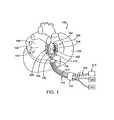
- FIG. 1is a perspective view illustration of a human heart and an ablation device in position for performing an ablation procedure, according to one embodiment of the invention.
- FIG. 2is a perspective view of an ablation device, according to one embodiment of the invention.
- FIG. 2 ais a perspective view of the ablation device shown in FIG. 2 , with the ablation member removed.
- FIG. 3is a bottom-surface view of an ablation device, according to one embodiment of the invention.
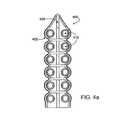
- FIG. 4is a perspective view of a flexible, elongate ablation device with two rows of suction apertures, according to one embodiment of the invention.
- FIG. 4 ais a bottom-surface view of the ablation device as shown in FIG. 4 , with the ablation member removed.
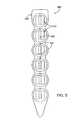
- FIG. 5is a bottom-side view of a flexible, elongate ablation device with one row of suction apertures, according to one embodiment of the invention.
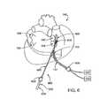
- FIG. 6is a perspective view of a human heart and an ablation device in position for performing an ablation procedure, according to one embodiment of the invention.
- FIG. 7is a perspective view of an elongate shaft ablation device, according to one embodiment of the invention.
- FIG. 7 ais a perspective view of the distal end of a shaft as in FIG. 6 , with straight jaws, according to one embodiment of the invention.
- FIG. 8is a perspective view of a human heart and an elongate shaft ablation device in position for ablating cardiac tissue, according to one embodiment of the invention.
- FIG. 9is a block diagram of a method for ablating tissue according to one embodiment of the invention.
- FIG. 10depicts aspects of an ablation device according to embodiments of the present invention.
- the present inventionrelates generally to medical devices and methods and more specifically to devices and methods for ablating cardiac tissue for treating cardiac arrhythmias such as atrial fibrillation.
- Ablation of cardiac tissue in various patternshas been shown to disrupt conduction pathways in the heart to ameliorate or eliminate AF or other arrhythmias.
- the devices and methodswill often be used to ablate epicardial tissue in the vicinity of at least one pulmonary vein, but various embodiments may be used to ablate other cardiac tissues in other locations on a heart.
- ablation devices of the inventioninclude at least one tissue contacting member for contacting a portion of the epicardial tissue of a heart, securing means for securing the ablation device to the tissue and at least one ablation member coupled with the contacting member for ablating at least a portion of the tissue.
- the deviceshave features which enable the device to attach to the epicardial surface with sufficient strength to allow the tissue to be stabilized via the device. For example, some embodiments may use suction force to secure the device to epicardial tissue and stabilize a beating heart to enable a beating heart ablation procedure.
- inventionsmay include other optional features, such as sensors for sensing whether tissue has been ablated, a support member with an arm for connecting the device to a positioning device, cooling apparatus for cooling epicardial tissue, visualization devices and/or the like.
- Some embodiments of the deviceare introducible into a patient via minimally invasive means, such as a minimally invasive incision, sheath, trocar or the like.
- Methods of the inventiongenerally include contacting a device with epicardial tissue, using a tissue contacting member on the device to secure the device to the tissue, and ablating the tissue with an ablation member on the device.
- the methodfurther includes additional steps such as positioning the device on the epicardial tissue, stabilizing cardiac tissue, cooling cardiac tissue, positioning the device using a positioning device, visualizing epicardial tissue with an imaging device and/or the like.
- the devices and methodsmay be used in veterinary or research contexts, to treat various heart conditions other than AF, to ablate cardiac tissue other than the epicardium and/or in any other suitable manner or context.
- an ablation device 100is shown in position for ablating epicardial tissue on a human heart 140 .
- a top view of ablation device 100is shown, the visible components of device 100 including a tissue contacting member 102 coupled with a suction connector 216 and a support member 104 having a support arm 106 .
- Tissue contacting member 102also includes multiple artery securing arms 108 for securing one or more coronary arteries.
- Suction connector 216is coupled with a suction cannula 112 , which in turn is coupled with a suction source 120 .
- Support arm 106is coupled via a clamp 116 to a positioner 114 , which in turn is coupled to a stabilizing device 118 for stabilizing positioner 114 .
- ablation device 100is coupled, via a wire 110 , to an energy source 122 .
- ablation device 100may be introduced into a patient through a minimally invasive introducer device, such as a sheath 124 , trocar or the like, as is represented in FIG. 1 by a simplified representation of sheath 124 .
- ablation device 100is shown in a position partially encircling the right superior pulmonary vein 142 and the right inferior pulmonary vein 144 .
- a positionis only one possible configuration for treating heart 140 .
- both of the right pulmonary veins 142 , 144may be completely encircled, only one may be partially or completely encircled, the left superior 148 and/or left inferior 150 pulmonary veins may be partially or completely encircled and/or various patterns may be ablated on the left atrium 146 , the right atrium 152 and/or the right and left ventricles (not labeled).
- Any ablation pattern suitable for heart treatmentmay be accomplished by one or more embodiments of the present invention.
- the following descriptions of various embodimentsshould not be interpreted to narrow the scope of the invention as set forth in the claims.
- ablation device 100includes at least one tissue contacting member 102 coupled with at least one ablation member (not shown in FIG. 1 ).
- tissue contacting member 102One embodiment of a device which may be used as tissue contacting member 102 is described in U.S. patent application Ser. No. 60/182,048, filed on Feb. 11, 2000, the entire contents of which is hereby incorporated by reference.
- Ablation device 100 shown in FIG. 1actually includes two tissue contacting members 102 , one on either side of the right pulmonary veins 142 , 144 . Tissue contacting members 102 may be coupled together via support member 104 and suction connector 216 .
- tissue contacting member 102may include only one member, more than two members, a coupling member disposed between multiple arms and/or the like.
- tissue contacting member 102may be conical, linear, shaped as a flat pad or a flat elongate member or may have any other suitable configuration.
- tissue contacting members 102may have any suitable size and dimensions.
- tissue contacting members 102 and device 100in general have a shape and dimensions to contact and ablate epicardial tissue on heart 140 in a pattern partial encircling the right pulmonary veins 142 , 144 . Many other configurations and sizes are possible, as described further below.
- Tissue contacting members 102may be manufactured from any suitable material, such as a polymer, plastic, ceramic, a combination of materials or the like.
- tissue contacting members 102are manufactured from a liquid molded silicone rubber.
- the material used to make tissue contacting members 102is chosen to allow the members 102 to be at least partially deformable or malleable.
- Deformable tissue contacting members 102may allow ablation device 100 to be inserted into a patient and/or advanced to a surgical site within the patient via a minimally invasive incision or a minimally invasive introducer device, such as sheath 124 .
- tissue contacting members 102may also allow device 100 to conform to a surface of heart 140 , to enhance ablation of epicardial or other cardiac tissue.
- tissue contacting members 102include one or more artery securing arms 108 , for securing, exposing and/or occluding one or more coronary arteries via silastic tubing attached between the artery and securing arm 108 .
- Securing arms 108are generally made of the same material(s) as tissue contacting members 102 but may also suitably comprise other materials.
- tissue contacting members 102are coupled with support member 104 .
- Support member 104may be made of any suitable biocompatible material, such as titanium, stainless steel, nickel titanium alloy (Nitinol) or the like.
- Support member 104may be coupled with tissue contacting members 102 by any suitable means, such as but not limited to one or more adhesive substances, placement of a portion of support member 104 within a sleeve on tissue contacting members 102 or a combination of both.
- support member 104may also be malleable or deformable to allow for insertion of ablation device 100 through a minimally invasive sheath 124 and/or for enhancing conformability of device 100 to a surface of heart 140 .
- Support member 104typically includes at least one support arm 106 or similar protrusion or multiple protrusions for removably coupling ablation device 100 with positioner 114 or one or more other positioning devices.
- Positioner 114may comprise a flexible, positioning arm, with attachment means such as clamp 116 for attaching to support arm 106 and stabilizing device 118 for stabilizing positioner 114 .
- a flexible, articulating positioner 114may be of the type which rigidifies when tensile force is applied, such as via a tensioning wire. Any other suitable positioner 114 may alternatively be used.
- device 100may not include support member 104 .
- Such devices 100may incorporate a connection arm onto a tissue contacting member 102 , may be positioned on heart 140 using a positioning device inserted through a separate incision, or may be positioned or manipulated by a physician or other user via any other suitable means.
- Tissue contacting members 102may also be coupled with one or more suction cannulas 112 to provide suction for enhancing contact of ablation device 100 with epicardial tissue.
- tissue contacting members 102may be directly coupled to one or more cannulas 112 or may be connected via one or more suction connectors 216 .
- a V-shaped suction connectoris used to couple the two tissue contacting members 102 with a common cannula 112 .
- Cannula 112is connected to suction source 120 , which may be a conventional wall suction or stand-alone suction source.
- cannula 112may be any suitable conventional cannula 112 , which are well known to those skilled in the art.
- Suction connector 216is typically comprised of the same material(s) as tissue contacting members 102 , but may also be made of a material or materials used to make cannula 112 .
- Suction connector 216may further include a nozzle 218 ( FIG. 2 ) for connecting to cannula 112 .
- Ablation device 100also includes at least one ablation member 210 ( FIG. 2 ).
- Ablation member 210typically receives energy from a separate energy source 122 , although ablation members 210 with internal energy sources are also contemplated. Where a separate energy source 122 is used, ablation member 210 may be coupled with source 122 by any suitable means. In one embodiment, for example, ablation member 210 may be coupled to energy source 122 with wire 110 . Wire 110 may be any suitable connector, such as fiber optic cable, electric cable, coaxial cable, ultrasound transmission device or the like. As is described further below, any suitable energy may be provided by energy source 122 for ablation and any means for transmitting energy to ablation member 210 is contemplated within the scope of the invention. In some embodiments, for example, energy may be transmitted remotely, so that no wires or other similar connecting devices are required. In other embodiments, radio frequency energy may be provided by an RF energy source and transmitted to ablation member 210 via conventional electrical wire(s) 110 .
- ablation member 210may be configured to transmit energy of any suitable quantity or force. For example, in some embodiments sufficient energy will be transmitted through ablation member 210 to ablate only epicardial tissue on a heart. In other embodiments, sufficient energy may be transmitted to cause one or more layers beneath the epicardial tissue to be ablated. In some embodiments, for example, one or more transmural lesions (across the entire wall of the heart) may be ablated. Typically, an amount of energy transmitted through ablation member 210 will be adjustable to create an desired ablation depth.
- a minimally invasive introducer sheath 124may be used for introducing one or more of the components shown in FIG. 1 into a patient.
- a sheathneed not be used and instead only a minimally invasive incision is used.
- multiple minimally invasive incisions and/or sheaths 124may be used for introducing various devices into a patient.
- one sheath 124may be used for introducing ablation device 100 and another sheath 124 may be used for introducing positioner 114 .
- devices and methods of the present inventionare often suitable for minimally invasive procedures, they may also typically be used in open surgical procedures, either with or without cardiopulmonary bypass, in various embodiments.
- tissue contacting surfaces 224may be given any configuration and sizes to contact cardiac tissue in an area around the tissue to be ablated.
- tissue contacting surface 224 on one tissue contacting member 102may have a length of approximately 1.25 in. and a width of approximately 0.5 in., with a space between the two tissue contacting surfaces measuring approximately 0.4 in.
- surfaces 224may be flat and smooth. In other embodiments, surfaces 224 are textured, curvilinear or otherwise shaped to enhance contact of tissue contacting members 102 with heart 140 . Some embodiments may further include one or more surface features 222 . Such features 222 may enhance friction between tissue contacting surfaces 224 and epicardial tissue and/or may provide an area for placement of additional features, such as irrigation apertures for cooling tissue or the like.
- Ablation member 210may include one or more ablation members for transmitting one or more of a variety of ablation agents to epicardium or other cardiac tissue.
- ablation member 210may comprise a single, continuous, RF ablation coil or wire for transmitting RF energy to cardiac tissue.
- ablation member 210may be multiple radio frequency devices or one or more cryogenic devices, ultrasound devices, laser devices, thermo-electric chip devices, chemical agent delivery devices, biological agent delivery devices, light-activated agent devices, thermal devices, microwave devices, or ablating drug delivery devices. Other suitable ablation devices are also contemplated within the scope of the invention.
- radio frequency ablation members 210may be bipolar or unipolar in various embodiments. In conjunction with any of these various embodiments, energy source 122 may provide any of the above-listed types of ablative energy or substance, any combination thereof or any other suitable ablative energy or substance.
- Ablation member 210may be given any configuration or size for ablating cardiac tissue.
- ablation member 210has two linear portions disposed along most of the lengths of contacting surfaces 224 of tissue contacting members 102 , and the linear portions are continuous with a curved portion 226 so that ablation member 210 is generally U-shaped.
- ablation member 210may continue proximally from tissue contacting members 102 in one or more arms 230 which eventually connect to wire 110 or other connective device.
- curved portion 226may be eliminated so that ablation member 210 comprises two linear ablation members connected to wire 110 via arms 230 .
- arms 230may be eliminated and ablation member 210 may be coupled directly to wire 110 without interposing arms.
- ablation members 210 and tissue contacting member 102may have any shapes, sizes, configurations or combinations of shapes and sizes to produce a desired ablation pattern on epicardial or other tissue of a heart.
- ablation members 210 and tissue contacting members 102are configured to partially or completely encircle or surround one pulmonary vein. In other embodiments, they may be configured to partially or completely surround two pulmonary veins on the same side of the heart, such as the left superior and left inferior pulmonary veins. In still other embodiments, the right and left inferior pulmonary veins or the right and left superior pulmonary veins may be partially or wholly encircled.
- all four pulmonary veinsmay be partially or completely encircled by ablation members 210 and tissue contacting member 102 .
- ablation member 210 or tissue contacting member 102may be steerable. Steerability means that an ablation member 210 or tissue contacting member 102 may be adjusted to fit around or next to one or more pulmonary veins or to otherwise assume a desired configuration.
- some embodimentsmay include a pull wire coupled with ablation member 210 and/or tissue contacting member 102 . The pull wire, when pulled, deflects ablation member 210 and/or tissue contacting member 102 to one side or around a curved structure.
- Other embodimentsmay include pushable wires, combinations of flexible and stiff portion and/or the like to provide steerability.
- tissue contacting members 102 and ablation members 210are contemplated for achieving such ablation patterns.
- a retractable RF coil 240 or other retractable ablation devicemay be incorporated into or used in conjunction with ablation member 210 as shown in FIG. 2 .
- Retractable coil 240could be housed within tissue contacting member 102 , for example, and could be released when desired to surround or encircled one or two pulmonary veins.
- ablation member 210in some embodiments comprises multiple thermoelectric chips disposed in a pattern on tissue contacting members 102 .
- ablation device 100 and ablation member 210are often shown as being generally U-shaped, many other configurations are possible. As described further below, a ablation device 100 may be conical in shape, with ablation member 210 being disposed in a circle at the base of the cone which contacts cardiac tissue. In other embodiments, device 100 may be configured as a flat patch and one or more linear or curvilinear ablation members 210 may be incorporated into the patch.
- ablation device 100may include a combination of multiple ablation members 210 to ablate a pattern on heart 140 such as: a first linear ablation member for contacting heart tissue between a left pulmonary vein and a right pulmonary vein; a second linear ablation member for contacting heart tissue at a location approximating a line extending to the atrioventricular groove; and a third linear ablation member for contacting heart tissue on a left atrial appendage.
- one or more of ablation members 210may overlap one another.
- each membermay be controllable on a separate radio frequency channel or other energy transmission channel.
- Tissue contacting members 102optionally include one or more attachment means for enhancing contact of ablation device 100 with epicardial or other cardiac tissue.
- one or more suction apertures 212are used.
- Each suction aperture 212generally includes a depressed surface and a small suction hole. The suction hole is connected to a lumen (not shown) within tissue contacting member 102 , and the lumen is then couplable with a suction cannula 122 or connector 216 for connecting to cannula 122 .
- Suction apertures 212may be given any suitable configuration, size or pattern.
- suction holesmay be disposed on tissue contacting member 102 is a largely linear pattern, as in FIG. 2 .
- suction aperturesmay be arranged in two parallel lines such that ablation member 210 is disposed between the two parallel lines of suction apertures 212 .
- ablation device 100may include one tissue contacting member 102 having a conical shape, with the base of the cone contacting epicardial tissue and the entire conical tissue contacting member 102 acting as one suction aperture.
- suction forcemay be applied via suction apertures 210 with sufficient strength to allow for stabilization and/or positioning of heart 140 .
- a physicianmay place ablation device 100 on a beating heart 140 , apply suction, and hold heart 140 is a relatively stable or reduced-motion position while performing an ablation procedure.
- the physicianmay also (or alternatively) turn or otherwise move heart 140 , using ablation device 100 , such as when a different angle of heart 140 would be advantageous for viewing or treating a portion of heart 140 .
- suction force applied through suction apertures 212may be of sufficient strength to dissect through one or more layers of adipose tissue covering epicardial tissue.
- suction apertures 212may allow for improved contact of the epicardial tissue by device and, thus, improved ablation.
- suction apertures 212may be replaced or supplemented by other means for securing ablation device 100 to epicardial tissue.
- an adhesivemay be applied to tissue contacting surfaces 224 .
- Such adhesives or other securing meansmay also be sufficiently strong, in some embodiments, to allow for positioning and/or stabilization of heart 140 .
- Tissue contacting members 102may also include one or more sensors 214 for sensing when tissue has been ablated.
- Sensors 214may include one or more thermal sensors, electrical sensors, thermoelectric sensors, microchips, thermistors, thermocouples and ultrasonic sensors. As shown in FIG. 2 , some embodiments include two or more paired sensors 214 , with one sensor of each pair on one side of ablation member 210 and the other sensor on the opposite side. In some embodiments, one sensor 214 transmits a signal through epicardial tissue to its paired sensor 214 . If epicardial tissue between the two paired sensors 214 has been ablated, then energy will transmit poorly through that ablated tissue. Thus, the receiving sensor 214 will receive reduced or no energy transmitted from the transmitting sensor 214 .
- tissue between two paired sensorshas not been ablated, the signal should travel through the tissue with only slight reduction in strength.
- paired sensors 214By using such paired sensors 214 and comparing signals received in different pairs, areas of ablation can be compared, to determine if all desired areas for ablation have been sufficiently ablated.
- Other configurations one or more sensors 214may also be used.
- tissue contacting members 102include a linear trough 250 in which ablation member 210 is placed, either removably or permanently. Positioning ablation member 210 in trough 250 may provide improved contact between ablation member 210 and epicardial tissue while also providing ablation device 100 with durability.
- Surface features 222are again shown in FIG. 2 a . These features may simply enhance contact of tissue contacting members 102 with epicardial tissue or may also contain additional features, such as sensors, irrigation apertures for allowing passage of irrigation fluid for cooling ablated tissue, small suction apertures and/or the like.
- ablation device 100may further include at least one cooling member for cooling a portion of ablated epicardial tissue, epicardial tissue surrounding an ablated area, other nearby tissues and/or a portion of device 100 .
- Cooling membersare not shown in the drawing figures, for purposes of clarity.
- a cooling membermay comprise any suitable device for cooling a tissue.
- cooling memberincludes at least one inlet port, for allowing introduction of a cooling substance into the member, a hollow internal cooling member, and at least one outlet port for allowing egress of the cooling substance.
- the cooling substanceitself may be carbon dioxide, any other suitable gas, saline or any other suitable liquid.
- the hollow cooling membercomprises a tubular member disposed within tissue contacting member 102 in general proximity with ablation member 210 .
- cooling membermay comprise a chamber for containing cooling substance or a series of irrigation holes for allowing cooling substance to flow out of tissue contacting member 102 to contact ablated or other epicardial tissue.
- Many other suitable cooling apparatusare contemplated for use within the scope of the present invention.
- Ablation device 300includes a tissue contacting member 302 , coupled with an ablation member 310 and a support member 304 .
- tissue contacting memberincludes a tissue contacting surface 324 , tissue attaching means including multiple suction apertures 312 and multiple artery securing arms 308 .
- Tissue contacting member 302is removably couplable with a suction cannula 318 via a V-shaped suction connector 316 .
- Ablation member 310is coupled with energy transmitting wire 314 for coupling with an energy source (not shown).
- Support member 304includes a support arm 306 (shown partially in dotted lines, since it extends on the opposite side of tissue contacting member 302 ) for coupling device 300 with a positioning device.
- tissue contacting member 302 , ablation member 310 and support member 304are all generally shaped as a square with a central area 303 and a top area 305 left open.
- tissue contacting member 302 , ablation member 310 and support member 304are all generally shaped as a square with a central area 303 and a top area 305 left open.
- Such a configurationmay be used, for example, to contact and ablate epicardial tissue almost completely encircling one or more pulmonary veins. Leaving top area 305 open may allow device 300 to be positioned around such veins or other vessels while still providing almost circumferential ablation.
- either central area 303 , top area 305 or bothmay be closed to provide for different contact and/or ablation patterns on epicardial tissue.
- one or more hingesmay be positioned on ablation device 300 to allow top area 305 to be closed after positioning device 300 around one or two pulmonary veins.
- any configuration, shape, size, dimensions or the likeare contemplated within the scope of the invention.
- tissue contacting member 402may be made of any suitable, flexible material, such as a silicone, polyurethane, polycarbonate, another suitable polymer or combination of polymers or the like.
- Tissue contacting member 402generally includes a tissue contacting surface 424 having multiple suction apertures 412 .
- Tissue contacting surface 424may be slightly concave (as shown), flat or may have any other suitable shape.
- Suction apertures 412are disposed in two parallel lines, one line on either side of ablation member 410 and communicate with suction lumens 414 and 416 .
- Suction lumens 414 , 416may be coupled with one or more suction cannulas or similar devices for providing suction force through suction apertures 412 .
- Other embodimentsmay include one common suction lumen for connection to a suction cannula.
- ablation member 410comprises a linear radio frequency coil.
- Ablation member 410may extend beyond the length of tissue contacting member 402 , either in a proximal or distal direction and may be coupled with a source of energy via a wire (not shown) or other connection device.
- one or more of the features described above, such as support members, retractable ablation elements, sensors, cooling members, positioning arms and/or the likemay be incorporated into or used with ablation device 400 .
- ablation device 400may simply include tissue contacting member 402 and linear ablation member 410 .
- Such an embodimentmay be advantageous for introduction through a narrow, minimally invasive introducer sheath, due to the device's flexibility and relatively small size.
- device 400may measure approximately 3.25 in. in length and approximately 0.9 in. wide and may further be deformable to a narrower configuration for insertion through a sheath.
- device 400may be sufficiently flexible to conform to curved surfaces of heart 140 , allowing for enhanced contact with and ablation of epicardial tissue.
- itmay sometimes be advantageous to ablate epicardial tissue in a linear pattern or in multiple line.
- Ablation device 400may be movable, to allow ablation in a first line, a second line, a third line and/or the like.
- tissue contacting member 402may include a trough 420 in which ablation member 410 may be positioned.
- ablation member 410may be a removable piece which may be removably attached to tissue contacting member 402 , at least partially disposed within trough 420 , so that one ablation member 410 may be used with multiple tissue contacting members 402 , one after another, for example if tissue contacting members 402 are single-use, disposable devices.
- FIG. 5shows yet another embodiment of ablation device 500 , including a tissue contacting member without an ablation member being shown.
- Device 500is similar to ablation device 400 , but tissue contacting member 502 has one row of suction apertures 512 rather than two and ablation member, placed in ablation trough 520 , overlays suction apertures 512 .
- Suction holes 522 shown in suction apertures 512demonstrate that the apertures sometimes include both a depressed or concave surface and one or more holes communicating with a suction lumen.
- Device 500may be advantageous for forming one or more linear ablations on heart 140 when there is minimal space in which to manipulate device 500 and/or when a narrow, minimally invasive incision or sheath is desired for insertion of device 500 .
- Device 500may be manufactured from any suitable material or combination of materials, such as those described above, may use any suitable form of ablation member and may include various additional features as desired.
- ablation device 400as described with reference to FIGS. 4 and 4 a is shown in position for performing epicardial ablation on a human heart 140 .
- ablation device 400may be placed in any desired position on heart 140 for ablating epicardial tissue.
- devicemay be placed adjacent one or both of the right pulmonary veins 142 , 144 , adjacent one or both of the left pulmonary veins 148 , 150 , or in any other suitable location.
- ablation device 400may be used to ablate tissue in a linear pattern at one location and then may be moved to ablated tissue in a linear pattern in another location.
- ablation device 400may be introduced into a patient via a minimally invasive device, such as a sheath 630 or trocar, and may be coupled with a source of suction 120 via a suction cannula 112 and with a source of ablative energy 122 via a wire 110 or other connective device.
- a minimally invasive devicesuch as a sheath 630 or trocar
- Ablative device 400may be positioned on heart 140 via a positioning device 602 which is introduced via a second minimally invasive incision or second sheath 620 .
- Second sheath 620may be placed at any suitable location on the patient to allow access to ablation device with the positioning device 602 .
- Positioning device 602may then be introduced through sheath and advanced to the position of ablation device 400 .
- Positioning device 602may then be used to secure device 400 , such as by opposable jaws 610 or any other suitable means, and position device 400 in a desired location on heart 140 .
- positioning devicemay further be used to reposition device 400 to perform ablation in multiple locations on heart 140 .
- the proximal end of positioning device 602may include a handle 604 for holding and manipulating device 602 and one or more actuators 606 , such as a trigger for opening and closing opposable jaws 610 or other distally positioned end effectors of device 602 .
- actuators 606such as a trigger for opening and closing opposable jaws 610 or other distally positioned end effectors of device 602 .
- Examples of positioning device 602may include, but are not limited to, conventional minimally invasive surgical devices such as laparoscopic surgical devices and the like.
- ablation device 700suitably includes at least one elongate shaft 702 having a proximal end 724 and a distal end 726 , a jaw member 704 coupled with shaft 702 near distal end 726 , at least one ablation member 712 , 714 coupled with jaw member 704 , and a handle 706 and at least one actuator 708 , 710 near the proximal end 724 for manipulating device 700 , opening and closing the jaw member, activating ablation member 712 , 714 and the like.
- Device 700is generally configured to be introduced through a minimally invasive sheath, trocar or incision, though it may also be used in open surgical procedures.
- Shaft 702may be made of any suitable material, such as metal, ceramic, polymers or any combination thereof, and may be rigid along its entire length or rigid in parts and flexible in one or more parts.
- the shaftmay be malleable, may articulate about at least one joint and/or may be steerable for positioning the device.
- the ablation memberis coupled with a portion of the shaft.
- Jaw member 704may be disposed on or near distal end 726 of shaft 702 and is generally configured to open and close to grasp epicardial or other tissue between the opposing jaws.
- jaw member 704may be coupled with shaft 702 at a hinge point 730 to allow for such opening and closing motion.
- An ablation memberis coupled with at least part of jaw member 704 .
- the ablation membermay use any suitable energy source for ablating tissue.
- multiple ablation members 712 , 714may be used.
- one electrode 712 of a bipolar ablation membermay be coupled with one opposing jaw and another electrode 714 may be coupled with the other opposing jaw.
- ablation members 712 , 714may include one unipolar ablation device or any of the ablation devices described with reference to various embodiments above.
- the jaw member and/or the ablation membermay be shaped to contact and ablate the epicardial tissue in a pattern such as, but not limited to, a U-shaped pattern, an L-shaped pattern, a circular pattern or a linear pattern.
- Actuators 708 , 710may have one or more various functions, such as opening and closing jaw member 704 , activating ablation members 712 , 714 , changing an angle of orientation of jaw member 704 , straightening or bending jaw member 704 and/or the like.
- One actuator 710for example, may comprise a trigger-like actuator while another actuator 708 may comprise a turnable dial.
- jaw member 704may have any suitable configuration for contacting a surface of a heart, for grasping epicardial or other tissue to be ablated and/or for placing ablation members 712 , 714 in contact with tissue to be ablated.
- jaw members 714may be straight, curved, bent or otherwise configured for contacting, grasping and/or ablating tissue.
- jaw member 704may be adjustable via an actuator 708 , 710 , so as to allow their shapes to be bent, straightened or the like during a procedure. With reference to FIG. 7 a , one embodiment of a straight jaw member 718 may allow jaw member 718 to be retracted within shaft (arrows).
- ablation members 720 , 722 on such straight jaw members 718may be bipolar RF members, unipolar RF members or any other suitable ablation devices.
- the devicemay further include an insulation member at least partially surrounding the device to protect body structures in the vicinity of the epicardial tissue to be ablated from damage due to heat or electrical current.
- the ablation membermay be adjustable to deliver two or more varying amounts of ablative energy to two or more locations on the epicardial tissue.
- Various embodimentsmay further include at least one sensor for sensing a quantity of ablation provided by the ablation member to the tissue.
- FIG. 8shows ablation device 700 , as just described, in a position for performing an ablation procedure on epicardial tissue of heart 140 .
- Device as shownwill ablate in a pattern approximating two lines adjacent the right pulmonary veins 142 , 144 .
- jaw member 704 and ablation members 712 , 714could alternatively be configured in any other suitable shape, size or configuration to ablate in other patterns on heart 140 .
- device 700may be moved to a variety of positions to ablate multiple patterns in multiple locations on the epicardial tissue.
- a method for ablating cardiac tissuesuitably includes contacting cardiac tissue with an ablation device 910 , securing the device to the tissue 920 and ablating at least a portion of the contacted, secured tissue 930 .
- contacting the cardiac tissue 910is preceded by advancing the device into the patient through a minimally invasive introducer device.
- Contacting the device with the tissue 910may include positioning the device using a positioning arm or other positioning device.
- securing the device to the tissue 920may also comprise invaginating a portion of epicardial tissue partially within one or more suction apertures and/or may include using one or more suction apertures to dissect through fatty tissue disposed over epicardium. Securing the device 920 may also involve securing with enough force to allow stabilization and/or positioning of the heart itself. And ablation of epicardial tissue 930 may involve ablation in any location or pattern as described above with reference to the inventive devices. Therefore, the descriptions of various methods provided herein are offered for exemplary purposes only and should not be interpreted to limit the scope of the invention as described in the claims.
- a method for ablating epicardial tissuemay include imaging the epicardial tissue and an area surrounding the tissue to be ablated, using a visualization device. Such a device may be coupled with the ablation device or may be a separate imaging device.
- an insufflation devicemay be inserted between the epicardium and the pericardium and insufflation fluid or gas may be introduced to form a space between the epicardium and pericardium. The space may be used to enhance visualization, allow for freer manipulation of devices near the site for ablation and the like.
- Another aspectmay include sensing ablation of epicardial tissue with one or more sensors, as described above.
- tissuemay optionally be cooled via a cooling member and/or irrigation of fluid into contact with the tissue.
- ablationis achieved and/or enhanced by delivery of one or more drugs to the tissue.
- a methodfirst includes advancing an ablation device through a minimally invasive introducer device into a patient and to a location for ablating epicardial tissue. The device is then contacted with the epicardial tissue and positioned on the tissue with a positioning arm or other device inserted through the same or a separate minimally invasive introducer or incision. Positioning device, in some embodiments, may be a flexible, rigidifying positioner which allows for positioning and then stabilizing with the same device.
- the ablation devicemay be placed in any suitable location for ablating epicardial tissue. In one embodiment, for example, ablation device will contact tissue at least partially encircling two pulmonary veins, such as the right superior and right inferior pulmonary veins. The ablation device may contact epicardial tissue directly adjacent the bases of the veins but may be configured to maintain a safe distance between the ablation member on the device and the actual veins.
- the devicemay be secured to the tissue by securing means, such as suction or adhesive.
- the devicemay be secured to the tissue sufficiently in some embodiments to allow the heart to be stabilized and/or positioned using the device and a positioner.
- a beating heartmay be stabilized to reduce or eliminate motion during an ablation procedure or may be pulled, turned or otherwise moved into an advantageous position for ablating, visualizing or treating the heart.
- Suction forcemay also be supplied in sufficient strength to dissect through a layer of adipose tissue overlying the epicardial tissue, which may provide improved contact of an ablation member with the epicardial tissue.
- tissuemay be ablated by delivering energy to an ablation member (or members) on the device.
- energymay include any suitable energy and may additionally or alternatively include one or more ablative drugs.
- tissuemay be cooled via cooling means and/or ablation of tissue may be sensed with one or more sensors.
- the devicemay be removed and placed in another location on the heart for an additional procedure or may be removed from the patient altogether.
- ablation device 1000comprises a largely flexible device which includes a tissue contacting member or tissue securing member 1002 and an ablation member or energy transmission member 1010 .
- device 1000may include at least one needle 1005 coupled with the energy transmission member 1010 for insertion into the heart tissue to enhance the application of energy to the heart tissue.
- the energyis transmitted from a tip of each needle 1005 .
- the needle 1005may be retractable.
- Tissue contacting member 1002may be made of any suitable, flexible material, such as a silicone, polyurethane, polycarbonate, another suitable polymer or combination of polymers or the like.
- Tissue contacting member 1002generally includes a tissue contacting surface 1024 having multiple suction apertures 1012 .
- Tissue contacting surface 1024may be slightly concave (as shown), flat or may have any other suitable shape.
- Suction apertures 1012are disposed in two parallel lines, one line on either side of ablation member 1010 and communicate with suction lumens 1014 and 1016 .
- Suction lumens 1014 , 1016may be coupled with one or more suction cannulas or similar devices for providing suction force through suction apertures 1012 .
- Other embodimentsmay include one common suction lumen for connection to a suction cannula.
- FIG. 10shows an ablation device 1000 .
- tissue contacting members 1002are coupled with support member 1004 .
- Support member 1004may be coupled with tissue contacting member 1002 by any suitable means, such as but not limited to one or more adhesive substances, placement of a portion of support member 1004 within a sleeve 1005 on tissue contacting member 1002 or a combination of both.
- Tissue contacting members 1002may be coupled together via support member 1004 .
Landscapes
- Health & Medical Sciences (AREA)
- Life Sciences & Earth Sciences (AREA)
- Surgery (AREA)
- Engineering & Computer Science (AREA)
- General Health & Medical Sciences (AREA)
- Veterinary Medicine (AREA)
- Public Health (AREA)
- Physics & Mathematics (AREA)
- Nuclear Medicine, Radiotherapy & Molecular Imaging (AREA)
- Animal Behavior & Ethology (AREA)
- Biomedical Technology (AREA)
- Heart & Thoracic Surgery (AREA)
- Medical Informatics (AREA)
- Molecular Biology (AREA)
- Otolaryngology (AREA)
- Plasma & Fusion (AREA)
- Biophysics (AREA)
- Radiology & Medical Imaging (AREA)
- Pathology (AREA)
- Optics & Photonics (AREA)
- Electromagnetism (AREA)
- Cardiology (AREA)
- Surgical Instruments (AREA)
Abstract
Description
Claims (13)
Priority Applications (6)
| Application Number | Priority Date | Filing Date | Title |
|---|---|---|---|
| US12/255,076US8535307B2 (en) | 2001-12-04 | 2008-10-21 | Cardiac treatment devices and methods |
| US12/971,774US9072522B2 (en) | 2001-12-04 | 2010-12-17 | Adjustable clamp systems and methods |
| US14/024,434US20140012254A1 (en) | 2001-12-04 | 2013-09-11 | Cardiac treatment devices and methods |
| US14/740,514US9445864B2 (en) | 2001-12-04 | 2015-06-16 | Adjustable clamp systems and methods |
| US15/271,078US10398495B2 (en) | 2001-12-04 | 2016-09-20 | Adjustable clamp systems and methods |
| US16/160,755US11304748B2 (en) | 2001-12-04 | 2018-10-15 | Cardiac treatment devices and methods |
Applications Claiming Priority (5)
| Application Number | Priority Date | Filing Date | Title |
|---|---|---|---|
| US33707001P | 2001-12-04 | 2001-12-04 | |
| US10/272,446US6849075B2 (en) | 2001-12-04 | 2002-10-15 | Cardiac ablation devices and methods |
| US10/410,618US7226448B2 (en) | 2001-12-04 | 2003-04-08 | Cardiac treatment devices and methods |
| US11/148,611US7819867B2 (en) | 2001-12-04 | 2005-06-08 | Cardiac treatment devices and methods |
| US12/255,076US8535307B2 (en) | 2001-12-04 | 2008-10-21 | Cardiac treatment devices and methods |
Related Parent Applications (1)
| Application Number | Title | Priority Date | Filing Date |
|---|---|---|---|
| US11/148,611ContinuationUS7819867B2 (en) | 2001-12-04 | 2005-06-08 | Cardiac treatment devices and methods |
Related Child Applications (1)
| Application Number | Title | Priority Date | Filing Date |
|---|---|---|---|
| US14/024,434ContinuationUS20140012254A1 (en) | 2001-12-04 | 2013-09-11 | Cardiac treatment devices and methods |
Publications (2)
| Publication Number | Publication Date |
|---|---|
| US20090076501A1 US20090076501A1 (en) | 2009-03-19 |
| US8535307B2true US8535307B2 (en) | 2013-09-17 |
Family
ID=33298313
Family Applications (5)
| Application Number | Title | Priority Date | Filing Date |
|---|---|---|---|
| US10/410,618Expired - LifetimeUS7226448B2 (en) | 2001-12-04 | 2003-04-08 | Cardiac treatment devices and methods |
| US11/148,611Active2026-11-15US7819867B2 (en) | 2001-12-04 | 2005-06-08 | Cardiac treatment devices and methods |
| US12/255,076Expired - LifetimeUS8535307B2 (en) | 2001-12-04 | 2008-10-21 | Cardiac treatment devices and methods |
| US14/024,434AbandonedUS20140012254A1 (en) | 2001-12-04 | 2013-09-11 | Cardiac treatment devices and methods |
| US16/160,755Expired - LifetimeUS11304748B2 (en) | 2001-12-04 | 2018-10-15 | Cardiac treatment devices and methods |
Family Applications Before (2)
| Application Number | Title | Priority Date | Filing Date |
|---|---|---|---|
| US10/410,618Expired - LifetimeUS7226448B2 (en) | 2001-12-04 | 2003-04-08 | Cardiac treatment devices and methods |
| US11/148,611Active2026-11-15US7819867B2 (en) | 2001-12-04 | 2005-06-08 | Cardiac treatment devices and methods |
Family Applications After (2)
| Application Number | Title | Priority Date | Filing Date |
|---|---|---|---|
| US14/024,434AbandonedUS20140012254A1 (en) | 2001-12-04 | 2013-09-11 | Cardiac treatment devices and methods |
| US16/160,755Expired - LifetimeUS11304748B2 (en) | 2001-12-04 | 2018-10-15 | Cardiac treatment devices and methods |
Country Status (2)
| Country | Link |
|---|---|
| US (5) | US7226448B2 (en) |
| WO (1) | WO2004091373A2 (en) |
Cited By (2)
| Publication number | Priority date | Publication date | Assignee | Title |
|---|---|---|---|---|
| US11191547B2 (en) | 2018-01-26 | 2021-12-07 | Syntheon 2.0, LLC | Left atrial appendage clipping device and methods for clipping the LAA |
| US11793524B2 (en) | 2019-05-03 | 2023-10-24 | Medtronic, Inc. | Recapturable left atrial appendage clipping device and methods for recapturing a left atrial appendage clip |
Families Citing this family (249)
| Publication number | Priority date | Publication date | Assignee | Title |
|---|---|---|---|---|
| US7445594B1 (en) | 1995-09-20 | 2008-11-04 | Medtronic, Inc. | Method and apparatus for temporarily immobilizing a local area of tissue |
| BR9913759A (en)* | 1998-09-15 | 2001-06-12 | Medtronic Inc | System to temporarily immobilize an area of tissue, and system to stabilize tissue |
| US11229472B2 (en) | 2001-06-12 | 2022-01-25 | Cilag Gmbh International | Modular battery powered handheld surgical instrument with multiple magnetic position sensors |
| US7338441B2 (en)* | 2001-09-06 | 2008-03-04 | Houser Russell A | Superelastic/shape memory tissue stabilizers and surgical instruments |
| US12121289B2 (en)* | 2008-05-09 | 2024-10-22 | Atricure, Inc. | Conduction block systems and methods |
| US7399300B2 (en)* | 2001-12-04 | 2008-07-15 | Endoscopic Technologies, Inc. | Cardiac ablation devices and methods |
| US7749157B2 (en)* | 2001-12-04 | 2010-07-06 | Estech, Inc. (Endoscopic Technologies, Inc.) | Methods and devices for minimally invasive cardiac surgery for atrial fibrillation |
| US7226448B2 (en)* | 2001-12-04 | 2007-06-05 | Estech, Inc. (Endoscopic Technologies, Inc.) | Cardiac treatment devices and methods |
| US7591818B2 (en) | 2001-12-04 | 2009-09-22 | Endoscopic Technologies, Inc. | Cardiac ablation devices and methods |
| US9072522B2 (en)* | 2001-12-04 | 2015-07-07 | Atricure, Inc. | Adjustable clamp systems and methods |
| US8235990B2 (en) | 2002-06-14 | 2012-08-07 | Ncontact Surgical, Inc. | Vacuum coagulation probes |
| US6893442B2 (en) | 2002-06-14 | 2005-05-17 | Ablatrics, Inc. | Vacuum coagulation probe for atrial fibrillation treatment |
| US7572257B2 (en)* | 2002-06-14 | 2009-08-11 | Ncontact Surgical, Inc. | Vacuum coagulation and dissection probes |
| US7063698B2 (en) | 2002-06-14 | 2006-06-20 | Ncontact Surgical, Inc. | Vacuum coagulation probes |
| US9439714B2 (en)* | 2003-04-29 | 2016-09-13 | Atricure, Inc. | Vacuum coagulation probes |
| US7494460B2 (en)* | 2002-08-21 | 2009-02-24 | Medtronic, Inc. | Methods and apparatus providing suction-assisted tissue engagement through a minimally invasive incision |
| AU2003296379A1 (en)* | 2002-12-06 | 2004-06-30 | Estech, Inc. (Endoscopic Technologies, Inc.) | Methods and devices for cardiac surgery |
| DE602004012232T2 (en)* | 2003-01-31 | 2009-03-12 | Smith & Nephew, Inc., Andover | CARTILAGE TREATMENT PROBE |
| US8066700B2 (en)* | 2003-01-31 | 2011-11-29 | Smith & Nephew, Inc. | Cartilage treatment probe |
| US7074218B2 (en)* | 2003-06-30 | 2006-07-11 | Ethicon, Inc. | Multi-modality ablation device |
| US7238179B2 (en)* | 2003-10-30 | 2007-07-03 | Medical Cv, Inc. | Apparatus and method for guided ablation treatment |
| US7232437B2 (en)* | 2003-10-30 | 2007-06-19 | Medical Cv, Inc. | Assessment of lesion transmurality |
| US7238180B2 (en)* | 2003-10-30 | 2007-07-03 | Medicalcv Inc. | Guided ablation with end-fire fiber |
| WO2005044124A1 (en) | 2003-10-30 | 2005-05-19 | Medical Cv, Inc. | Apparatus and method for laser treatment |
| US8182501B2 (en) | 2004-02-27 | 2012-05-22 | Ethicon Endo-Surgery, Inc. | Ultrasonic surgical shears and method for sealing a blood vessel using same |
| US20060079879A1 (en) | 2004-10-08 | 2006-04-13 | Faller Craig N | Actuation mechanism for use with an ultrasonic surgical instrument |
| US20060271035A1 (en)* | 2005-05-27 | 2006-11-30 | Cardima, Inc. | Bipolar tissue dessication system and method |
| US20070073281A1 (en)* | 2005-09-16 | 2007-03-29 | Medicalcv, Inc. | Guided ablation with motion control |
| US20070073277A1 (en) | 2005-09-16 | 2007-03-29 | Medicalcv, Inc. | Controlled guided ablation treatment |
| US20070073280A1 (en)* | 2005-09-16 | 2007-03-29 | Medicalcv, Inc. | End-fire guided ablation |
| US20070073278A1 (en) | 2005-09-16 | 2007-03-29 | Johnson Kevin C | Cardiac Ablation Dosing |
| US20070191713A1 (en) | 2005-10-14 | 2007-08-16 | Eichmann Stephen E | Ultrasonic device for cutting and coagulating |
| US20070135686A1 (en)* | 2005-12-14 | 2007-06-14 | Pruitt John C Jr | Tools and methods for epicardial access |
| US7621930B2 (en) | 2006-01-20 | 2009-11-24 | Ethicon Endo-Surgery, Inc. | Ultrasound medical instrument having a medical ultrasonic blade |
| US20070198046A1 (en)* | 2006-02-17 | 2007-08-23 | Medicalcv, Inc. | Surgical visualization tool |
| AU2007248456A1 (en)* | 2006-05-05 | 2007-11-15 | The Cleveland Clinic Foundation | Apparatus and method for stabilizing body tissue |
| JP5054116B2 (en)* | 2006-11-09 | 2012-10-24 | エヌコンタクト サージカル, インコーポレイテッド | Vacuum coagulation probe |
| US10166066B2 (en) | 2007-03-13 | 2019-01-01 | University Of Virginia Patent Foundation | Epicardial ablation catheter and method of use |
| WO2008118737A1 (en) | 2007-03-22 | 2008-10-02 | University Of Virginia Patent Foundation | Electrode catheter for ablation purposes and related method thereof |
| US11058354B2 (en) | 2007-03-19 | 2021-07-13 | University Of Virginia Patent Foundation | Access needle with direct visualization and related methods |
| US9468396B2 (en) | 2007-03-19 | 2016-10-18 | University Of Virginia Patent Foundation | Systems and methods for determining location of an access needle in a subject |
| WO2011103456A2 (en) | 2010-02-18 | 2011-08-25 | University Of Virginia Patent Foundation | System, method, and computer program product for simulating epicardial electrophysiology procedures |
| BRPI0809127B8 (en) | 2007-03-19 | 2021-06-22 | Univ Virginia Patent Foundation | devices and methods for accessing one or more locations and detecting pressure at one or more locations |
| US8142461B2 (en) | 2007-03-22 | 2012-03-27 | Ethicon Endo-Surgery, Inc. | Surgical instruments |
| US8057498B2 (en) | 2007-11-30 | 2011-11-15 | Ethicon Endo-Surgery, Inc. | Ultrasonic surgical instrument blades |
| US8911460B2 (en) | 2007-03-22 | 2014-12-16 | Ethicon Endo-Surgery, Inc. | Ultrasonic surgical instruments |
| US8216221B2 (en)* | 2007-05-21 | 2012-07-10 | Estech, Inc. | Cardiac ablation systems and methods |
| US8523889B2 (en) | 2007-07-27 | 2013-09-03 | Ethicon Endo-Surgery, Inc. | Ultrasonic end effectors with increased active length |
| US8808319B2 (en) | 2007-07-27 | 2014-08-19 | Ethicon Endo-Surgery, Inc. | Surgical instruments |
| US9044261B2 (en) | 2007-07-31 | 2015-06-02 | Ethicon Endo-Surgery, Inc. | Temperature controlled ultrasonic surgical instruments |
| US8512365B2 (en) | 2007-07-31 | 2013-08-20 | Ethicon Endo-Surgery, Inc. | Surgical instruments |
| US8430898B2 (en) | 2007-07-31 | 2013-04-30 | Ethicon Endo-Surgery, Inc. | Ultrasonic surgical instruments |
| EP2217157A2 (en) | 2007-10-05 | 2010-08-18 | Ethicon Endo-Surgery, Inc. | Ergonomic surgical instruments |
| US20100241185A1 (en) | 2007-11-09 | 2010-09-23 | University Of Virginia Patent Foundation | Steerable epicardial pacing catheter system placed via the subxiphoid process |
| US10010339B2 (en) | 2007-11-30 | 2018-07-03 | Ethicon Llc | Ultrasonic surgical blades |
| US10136909B2 (en)* | 2007-12-20 | 2018-11-27 | Atricure, Inc. | Magnetic introducer systems and methods |
| US8353907B2 (en) | 2007-12-21 | 2013-01-15 | Atricure, Inc. | Ablation device with internally cooled electrodes |
| US8998892B2 (en) | 2007-12-21 | 2015-04-07 | Atricure, Inc. | Ablation device with cooled electrodes and methods of use |
| US9603674B2 (en)* | 2008-05-30 | 2017-03-28 | The Regents Of The University Of California | Method to protect the esophagus and other mediastinal structures during cardiac and thoracic interventions |
| US9089360B2 (en) | 2008-08-06 | 2015-07-28 | Ethicon Endo-Surgery, Inc. | Devices and techniques for cutting and coagulating tissue |
| US8295902B2 (en)* | 2008-11-11 | 2012-10-23 | Shifamed Holdings, Llc | Low profile electrode assembly |
| US9795442B2 (en) | 2008-11-11 | 2017-10-24 | Shifamed Holdings, Llc | Ablation catheters |
| US20100168568A1 (en)* | 2008-12-30 | 2010-07-01 | St. Jude Medical, Atrial Fibrillation Division Inc. | Combined Diagnostic and Therapeutic Device Using Aligned Energy Beams |
| US8430875B2 (en) | 2009-05-19 | 2013-04-30 | Estech, Inc. (Endoscopic Technologies, Inc.) | Magnetic navigation systems and methods |
| US9700339B2 (en) | 2009-05-20 | 2017-07-11 | Ethicon Endo-Surgery, Inc. | Coupling arrangements and methods for attaching tools to ultrasonic surgical instruments |
| US8920369B2 (en) | 2009-06-24 | 2014-12-30 | Shifamed Holdings, Llc | Steerable delivery sheaths |
| AU2010266027B2 (en)* | 2009-06-24 | 2015-05-07 | Shifamed Holdings, Llc | Steerable medical delivery devices and methods of use |
| US20100331838A1 (en)* | 2009-06-25 | 2010-12-30 | Estech, Inc. (Endoscopic Technologies, Inc.) | Transmurality clamp systems and methods |
| US8663220B2 (en) | 2009-07-15 | 2014-03-04 | Ethicon Endo-Surgery, Inc. | Ultrasonic surgical instruments |
| US8876712B2 (en) | 2009-07-29 | 2014-11-04 | Edwards Lifesciences Corporation | Intracardiac sheath stabilizer |
| US9572624B2 (en) | 2009-08-05 | 2017-02-21 | Atricure, Inc. | Bipolar belt systems and methods |
| US10123821B2 (en) | 2009-09-10 | 2018-11-13 | Atricure, Inc. | Scope and magnetic introducer systems and methods |
| US9642534B2 (en) | 2009-09-11 | 2017-05-09 | University Of Virginia Patent Foundation | Systems and methods for determining location of an access needle in a subject |
| US9050093B2 (en) | 2009-10-09 | 2015-06-09 | Ethicon Endo-Surgery, Inc. | Surgical generator for ultrasonic and electrosurgical devices |
| US10441345B2 (en) | 2009-10-09 | 2019-10-15 | Ethicon Llc | Surgical generator for ultrasonic and electrosurgical devices |
| US10172669B2 (en) | 2009-10-09 | 2019-01-08 | Ethicon Llc | Surgical instrument comprising an energy trigger lockout |
| US11090104B2 (en) | 2009-10-09 | 2021-08-17 | Cilag Gmbh International | Surgical generator for ultrasonic and electrosurgical devices |
| WO2011075328A1 (en) | 2009-12-14 | 2011-06-23 | Mayo Foundation For Medical Education And Research | Device and method for treating cardiac disorders by modulating autonomic response |
| US11229479B2 (en) | 2009-12-18 | 2022-01-25 | Atricure, Inc. | Adjustable clamp systems and methods |
| US8951272B2 (en) | 2010-02-11 | 2015-02-10 | Ethicon Endo-Surgery, Inc. | Seal arrangements for ultrasonically powered surgical instruments |
| US8486096B2 (en) | 2010-02-11 | 2013-07-16 | Ethicon Endo-Surgery, Inc. | Dual purpose surgical instrument for cutting and coagulating tissue |
| US8469981B2 (en) | 2010-02-11 | 2013-06-25 | Ethicon Endo-Surgery, Inc. | Rotatable cutting implement arrangements for ultrasonic surgical instruments |
| US8740898B2 (en)* | 2010-03-22 | 2014-06-03 | Covidien Lp | Surgical forceps |
| AU2011232335A1 (en) | 2010-03-24 | 2012-10-11 | Shifamed Holdings, Llc | Intravascular tissue disruption |
| US8834518B2 (en) | 2010-04-12 | 2014-09-16 | Ethicon Endo-Surgery, Inc. | Electrosurgical cutting and sealing instruments with cam-actuated jaws |
| US8709035B2 (en) | 2010-04-12 | 2014-04-29 | Ethicon Endo-Surgery, Inc. | Electrosurgical cutting and sealing instruments with jaws having a parallel closure motion |
| US9655677B2 (en) | 2010-05-12 | 2017-05-23 | Shifamed Holdings, Llc | Ablation catheters including a balloon and electrodes |
| AU2011252976A1 (en) | 2010-05-12 | 2012-11-08 | Shifamed Holdings, Llc | Low profile electrode assembly |
| US8685020B2 (en) | 2010-05-17 | 2014-04-01 | Ethicon Endo-Surgery, Inc. | Surgical instruments and end effectors therefor |
| GB2480498A (en) | 2010-05-21 | 2011-11-23 | Ethicon Endo Surgery Inc | Medical device comprising RF circuitry |
| US9005199B2 (en) | 2010-06-10 | 2015-04-14 | Ethicon Endo-Surgery, Inc. | Heat management configurations for controlling heat dissipation from electrosurgical instruments |
| US8795327B2 (en) | 2010-07-22 | 2014-08-05 | Ethicon Endo-Surgery, Inc. | Electrosurgical instrument with separate closure and cutting members |
| US9192431B2 (en) | 2010-07-23 | 2015-11-24 | Ethicon Endo-Surgery, Inc. | Electrosurgical cutting and sealing instrument |
| US8979890B2 (en) | 2010-10-01 | 2015-03-17 | Ethicon Endo-Surgery, Inc. | Surgical instrument with jaw member |
| US9072518B2 (en) | 2011-05-31 | 2015-07-07 | Atricure, Inc. | High-voltage pulse ablation systems and methods |
| US9259265B2 (en) | 2011-07-22 | 2016-02-16 | Ethicon Endo-Surgery, Llc | Surgical instruments for tensioning tissue |
| US9044243B2 (en) | 2011-08-30 | 2015-06-02 | Ethcon Endo-Surgery, Inc. | Surgical cutting and fastening device with descendible second trigger arrangement |
| CN106823131B (en) | 2011-09-30 | 2019-12-20 | 柯惠有限合伙公司 | Energy transfer device and method of use |
| US9333025B2 (en) | 2011-10-24 | 2016-05-10 | Ethicon Endo-Surgery, Llc | Battery initialization clip |
| WO2013119545A1 (en) | 2012-02-10 | 2013-08-15 | Ethicon-Endo Surgery, Inc. | Robotically controlled surgical instrument |
| US9439668B2 (en) | 2012-04-09 | 2016-09-13 | Ethicon Endo-Surgery, Llc | Switch arrangements for ultrasonic surgical instruments |
| US8961550B2 (en) | 2012-04-17 | 2015-02-24 | Indian Wells Medical, Inc. | Steerable endoluminal punch |
| US20140005705A1 (en) | 2012-06-29 | 2014-01-02 | Ethicon Endo-Surgery, Inc. | Surgical instruments with articulating shafts |
| US20140005640A1 (en) | 2012-06-28 | 2014-01-02 | Ethicon Endo-Surgery, Inc. | Surgical end effector jaw and electrode configurations |
| US9326788B2 (en) | 2012-06-29 | 2016-05-03 | Ethicon Endo-Surgery, Llc | Lockout mechanism for use with robotic electrosurgical device |
| US9820768B2 (en) | 2012-06-29 | 2017-11-21 | Ethicon Llc | Ultrasonic surgical instruments with control mechanisms |
| US9393037B2 (en) | 2012-06-29 | 2016-07-19 | Ethicon Endo-Surgery, Llc | Surgical instruments with articulating shafts |
| US9198714B2 (en) | 2012-06-29 | 2015-12-01 | Ethicon Endo-Surgery, Inc. | Haptic feedback devices for surgical robot |
| US9226767B2 (en) | 2012-06-29 | 2016-01-05 | Ethicon Endo-Surgery, Inc. | Closed feedback control for electrosurgical device |
| US9351754B2 (en) | 2012-06-29 | 2016-05-31 | Ethicon Endo-Surgery, Llc | Ultrasonic surgical instruments with distally positioned jaw assemblies |
| US9408622B2 (en) | 2012-06-29 | 2016-08-09 | Ethicon Endo-Surgery, Llc | Surgical instruments with articulating shafts |
| US20140005702A1 (en) | 2012-06-29 | 2014-01-02 | Ethicon Endo-Surgery, Inc. | Ultrasonic surgical instruments with distally positioned transducers |
| EP2900158B1 (en) | 2012-09-28 | 2020-04-15 | Ethicon LLC | Multi-function bi-polar forceps |
| US9095367B2 (en) | 2012-10-22 | 2015-08-04 | Ethicon Endo-Surgery, Inc. | Flexible harmonic waveguides/blades for surgical instruments |
| US20140135804A1 (en) | 2012-11-15 | 2014-05-15 | Ethicon Endo-Surgery, Inc. | Ultrasonic and electrosurgical devices |
| US10226273B2 (en) | 2013-03-14 | 2019-03-12 | Ethicon Llc | Mechanical fasteners for use with surgical energy devices |
| US10098694B2 (en) | 2013-04-08 | 2018-10-16 | Apama Medical, Inc. | Tissue ablation and monitoring thereof |
| US10349824B2 (en) | 2013-04-08 | 2019-07-16 | Apama Medical, Inc. | Tissue mapping and visualization systems |
| KR20150140760A (en) | 2013-04-08 | 2015-12-16 | 아파마 메디칼, 인크. | Cardiac ablation catheters and methods of use thereof |
| WO2014172398A1 (en)* | 2013-04-15 | 2014-10-23 | Mayo Foundation For Medical Education And Research | Method and apparatus for percutaneous epicardial ablation of cardiac ganglionated plexi without myocardial injury |
| US9295514B2 (en) | 2013-08-30 | 2016-03-29 | Ethicon Endo-Surgery, Llc | Surgical devices with close quarter articulation features |
| US9814514B2 (en) | 2013-09-13 | 2017-11-14 | Ethicon Llc | Electrosurgical (RF) medical instruments for cutting and coagulating tissue |
| US9861428B2 (en) | 2013-09-16 | 2018-01-09 | Ethicon Llc | Integrated systems for electrosurgical steam or smoke control |
| US20150080876A1 (en)* | 2013-09-16 | 2015-03-19 | Ethoicon Endo-Surgery, Inc | Integrated systems for electrosurgical steam or smoke control |
| US9265926B2 (en) | 2013-11-08 | 2016-02-23 | Ethicon Endo-Surgery, Llc | Electrosurgical devices |
| US9526565B2 (en) | 2013-11-08 | 2016-12-27 | Ethicon Endo-Surgery, Llc | Electrosurgical devices |
| GB2521228A (en) | 2013-12-16 | 2015-06-17 | Ethicon Endo Surgery Inc | Medical device |
| GB2521229A (en) | 2013-12-16 | 2015-06-17 | Ethicon Endo Surgery Inc | Medical device |
| US9795436B2 (en) | 2014-01-07 | 2017-10-24 | Ethicon Llc | Harvesting energy from a surgical generator |
| US9408660B2 (en) | 2014-01-17 | 2016-08-09 | Ethicon Endo-Surgery, Llc | Device trigger dampening mechanism |
| US9554854B2 (en) | 2014-03-18 | 2017-01-31 | Ethicon Endo-Surgery, Llc | Detecting short circuits in electrosurgical medical devices |
| DE102014004290A1 (en)* | 2014-03-26 | 2015-10-01 | Olympus Winter & Ibe Gmbh | Urological instrument |
| US10463421B2 (en) | 2014-03-27 | 2019-11-05 | Ethicon Llc | Two stage trigger, clamp and cut bipolar vessel sealer |
| US10092310B2 (en) | 2014-03-27 | 2018-10-09 | Ethicon Llc | Electrosurgical devices |
| US10524852B1 (en) | 2014-03-28 | 2020-01-07 | Ethicon Llc | Distal sealing end effector with spacers |
| US9737355B2 (en) | 2014-03-31 | 2017-08-22 | Ethicon Llc | Controlling impedance rise in electrosurgical medical devices |
| US9913680B2 (en) | 2014-04-15 | 2018-03-13 | Ethicon Llc | Software algorithms for electrosurgical instruments |
| US9757186B2 (en) | 2014-04-17 | 2017-09-12 | Ethicon Llc | Device status feedback for bipolar tissue spacer |
| US9700333B2 (en) | 2014-06-30 | 2017-07-11 | Ethicon Llc | Surgical instrument with variable tissue compression |
| US10285724B2 (en) | 2014-07-31 | 2019-05-14 | Ethicon Llc | Actuation mechanisms and load adjustment assemblies for surgical instruments |
| US9877776B2 (en) | 2014-08-25 | 2018-01-30 | Ethicon Llc | Simultaneous I-beam and spring driven cam jaw closure mechanism |
| US10194976B2 (en) | 2014-08-25 | 2019-02-05 | Ethicon Llc | Lockout disabling mechanism |
| US10194972B2 (en) | 2014-08-26 | 2019-02-05 | Ethicon Llc | Managing tissue treatment |
| US10639092B2 (en) | 2014-12-08 | 2020-05-05 | Ethicon Llc | Electrode configurations for surgical instruments |
| US10092348B2 (en) | 2014-12-22 | 2018-10-09 | Ethicon Llc | RF tissue sealer, shear grip, trigger lock mechanism and energy activation |
| US9848937B2 (en) | 2014-12-22 | 2017-12-26 | Ethicon Llc | End effector with detectable configurations |
| US10111699B2 (en) | 2014-12-22 | 2018-10-30 | Ethicon Llc | RF tissue sealer, shear grip, trigger lock mechanism and energy activation |
| US10159524B2 (en) | 2014-12-22 | 2018-12-25 | Ethicon Llc | High power battery powered RF amplifier topology |
| US10245095B2 (en) | 2015-02-06 | 2019-04-02 | Ethicon Llc | Electrosurgical instrument with rotation and articulation mechanisms |
| US10342602B2 (en) | 2015-03-17 | 2019-07-09 | Ethicon Llc | Managing tissue treatment |
| US10321950B2 (en) | 2015-03-17 | 2019-06-18 | Ethicon Llc | Managing tissue treatment |
| US10595929B2 (en) | 2015-03-24 | 2020-03-24 | Ethicon Llc | Surgical instruments with firing system overload protection mechanisms |
| US10420537B2 (en) | 2015-03-27 | 2019-09-24 | Shifamed Holdings, Llc | Steerable medical devices, systems, and methods of use |
| US10314638B2 (en) | 2015-04-07 | 2019-06-11 | Ethicon Llc | Articulating radio frequency (RF) tissue seal with articulating state sensing |
| US10117702B2 (en) | 2015-04-10 | 2018-11-06 | Ethicon Llc | Surgical generator systems and related methods |
| US10130410B2 (en) | 2015-04-17 | 2018-11-20 | Ethicon Llc | Electrosurgical instrument including a cutting member decouplable from a cutting member trigger |
| JP6820864B2 (en) | 2015-04-24 | 2021-01-27 | カリラ メディカル インコーポレイテッド | Manipulable medical devices, systems and usage |
| US9872725B2 (en) | 2015-04-29 | 2018-01-23 | Ethicon Llc | RF tissue sealer with mode selection |
| US11020140B2 (en) | 2015-06-17 | 2021-06-01 | Cilag Gmbh International | Ultrasonic surgical blade for use with ultrasonic surgical instruments |
| US11141213B2 (en) | 2015-06-30 | 2021-10-12 | Cilag Gmbh International | Surgical instrument with user adaptable techniques |
| US10034704B2 (en) | 2015-06-30 | 2018-07-31 | Ethicon Llc | Surgical instrument with user adaptable algorithms |
| US10898256B2 (en) | 2015-06-30 | 2021-01-26 | Ethicon Llc | Surgical system with user adaptable techniques based on tissue impedance |
| US10357303B2 (en) | 2015-06-30 | 2019-07-23 | Ethicon Llc | Translatable outer tube for sealing using shielded lap chole dissector |
| US11129669B2 (en) | 2015-06-30 | 2021-09-28 | Cilag Gmbh International | Surgical system with user adaptable techniques based on tissue type |
| US11051873B2 (en) | 2015-06-30 | 2021-07-06 | Cilag Gmbh International | Surgical system with user adaptable techniques employing multiple energy modalities based on tissue parameters |
| US10154852B2 (en) | 2015-07-01 | 2018-12-18 | Ethicon Llc | Ultrasonic surgical blade with improved cutting and coagulation features |
| US10194973B2 (en) | 2015-09-30 | 2019-02-05 | Ethicon Llc | Generator for digitally generating electrical signal waveforms for electrosurgical and ultrasonic surgical instruments |
| US10959771B2 (en) | 2015-10-16 | 2021-03-30 | Ethicon Llc | Suction and irrigation sealing grasper |
| US10595930B2 (en) | 2015-10-16 | 2020-03-24 | Ethicon Llc | Electrode wiping surgical device |
| CN108366715A (en) | 2015-11-09 | 2018-08-03 | 施菲姆德控股有限责任公司 | Steering assembly and application method for medical treatment device |
| EP4302713A3 (en) | 2015-11-16 | 2024-03-13 | Boston Scientific Scimed, Inc. | Energy delivery devices |
| US10179022B2 (en) | 2015-12-30 | 2019-01-15 | Ethicon Llc | Jaw position impedance limiter for electrosurgical instrument |
| US10959806B2 (en) | 2015-12-30 | 2021-03-30 | Ethicon Llc | Energized medical device with reusable handle |
| US10575892B2 (en) | 2015-12-31 | 2020-03-03 | Ethicon Llc | Adapter for electrical surgical instruments |
| US11129670B2 (en) | 2016-01-15 | 2021-09-28 | Cilag Gmbh International | Modular battery powered handheld surgical instrument with selective application of energy based on button displacement, intensity, or local tissue characterization |
| US10716615B2 (en) | 2016-01-15 | 2020-07-21 | Ethicon Llc | Modular battery powered handheld surgical instrument with curved end effectors having asymmetric engagement between jaw and blade |
| US11229471B2 (en) | 2016-01-15 | 2022-01-25 | Cilag Gmbh International | Modular battery powered handheld surgical instrument with selective application of energy based on tissue characterization |
| US11051840B2 (en) | 2016-01-15 | 2021-07-06 | Ethicon Llc | Modular battery powered handheld surgical instrument with reusable asymmetric handle housing |
| US12193698B2 (en) | 2016-01-15 | 2025-01-14 | Cilag Gmbh International | Method for self-diagnosing operation of a control switch in a surgical instrument system |
| US10555769B2 (en) | 2016-02-22 | 2020-02-11 | Ethicon Llc | Flexible circuits for electrosurgical instrument |
| US10646269B2 (en) | 2016-04-29 | 2020-05-12 | Ethicon Llc | Non-linear jaw gap for electrosurgical instruments |
| US10485607B2 (en) | 2016-04-29 | 2019-11-26 | Ethicon Llc | Jaw structure with distal closure for electrosurgical instruments |
| US10856934B2 (en) | 2016-04-29 | 2020-12-08 | Ethicon Llc | Electrosurgical instrument with electrically conductive gap setting and tissue engaging members |
| US10987156B2 (en) | 2016-04-29 | 2021-04-27 | Ethicon Llc | Electrosurgical instrument with electrically conductive gap setting member and electrically insulative tissue engaging members |
| US10702329B2 (en) | 2016-04-29 | 2020-07-07 | Ethicon Llc | Jaw structure with distal post for electrosurgical instruments |
| US10456193B2 (en) | 2016-05-03 | 2019-10-29 | Ethicon Llc | Medical device with a bilateral jaw configuration for nerve stimulation |
| US10245064B2 (en) | 2016-07-12 | 2019-04-02 | Ethicon Llc | Ultrasonic surgical instrument with piezoelectric central lumen transducer |
| US10893883B2 (en) | 2016-07-13 | 2021-01-19 | Ethicon Llc | Ultrasonic assembly for use with ultrasonic surgical instruments |
| US10842522B2 (en) | 2016-07-15 | 2020-11-24 | Ethicon Llc | Ultrasonic surgical instruments having offset blades |
| US10376305B2 (en) | 2016-08-05 | 2019-08-13 | Ethicon Llc | Methods and systems for advanced harmonic energy |
| US10201352B2 (en)* | 2016-08-08 | 2019-02-12 | Atricure, Inc. | Robotic Assisted clip applier |
| US10285723B2 (en) | 2016-08-09 | 2019-05-14 | Ethicon Llc | Ultrasonic surgical blade with improved heel portion |
| USD847990S1 (en) | 2016-08-16 | 2019-05-07 | Ethicon Llc | Surgical instrument |
| US10952759B2 (en) | 2016-08-25 | 2021-03-23 | Ethicon Llc | Tissue loading of a surgical instrument |
| US10736649B2 (en) | 2016-08-25 | 2020-08-11 | Ethicon Llc | Electrical and thermal connections for ultrasonic transducer |
| US10751117B2 (en) | 2016-09-23 | 2020-08-25 | Ethicon Llc | Electrosurgical instrument with fluid diverter |
| US10603064B2 (en) | 2016-11-28 | 2020-03-31 | Ethicon Llc | Ultrasonic transducer |
| US11266430B2 (en) | 2016-11-29 | 2022-03-08 | Cilag Gmbh International | End effector control and calibration |
| US11033325B2 (en) | 2017-02-16 | 2021-06-15 | Cilag Gmbh International | Electrosurgical instrument with telescoping suction port and debris cleaner |
| US10799284B2 (en) | 2017-03-15 | 2020-10-13 | Ethicon Llc | Electrosurgical instrument with textured jaws |
| US11497546B2 (en) | 2017-03-31 | 2022-11-15 | Cilag Gmbh International | Area ratios of patterned coatings on RF electrodes to reduce sticking |
| US10603117B2 (en) | 2017-06-28 | 2020-03-31 | Ethicon Llc | Articulation state detection mechanisms |
| US10820920B2 (en) | 2017-07-05 | 2020-11-03 | Ethicon Llc | Reusable ultrasonic medical devices and methods of their use |
| US11033323B2 (en) | 2017-09-29 | 2021-06-15 | Cilag Gmbh International | Systems and methods for managing fluid and suction in electrosurgical systems |
| US11490951B2 (en) | 2017-09-29 | 2022-11-08 | Cilag Gmbh International | Saline contact with electrodes |
| US11484358B2 (en) | 2017-09-29 | 2022-11-01 | Cilag Gmbh International | Flexible electrosurgical instrument |
| JP2022525823A (en) | 2019-01-10 | 2022-05-20 | アトリキュア, インコーポレイテッド | Surgical forceps |
| JP7189971B2 (en)* | 2019-01-28 | 2022-12-14 | オリンパス株式会社 | Electrode unit and endoscope system |
| US11723729B2 (en) | 2019-06-27 | 2023-08-15 | Cilag Gmbh International | Robotic surgical assembly coupling safety mechanisms |
| US11376082B2 (en) | 2019-06-27 | 2022-07-05 | Cilag Gmbh International | Robotic surgical system with local sensing of functional parameters based on measurements of multiple physical inputs |
| US11607278B2 (en) | 2019-06-27 | 2023-03-21 | Cilag Gmbh International | Cooperative robotic surgical systems |
| US11547468B2 (en) | 2019-06-27 | 2023-01-10 | Cilag Gmbh International | Robotic surgical system with safety and cooperative sensing control |
| US11413102B2 (en) | 2019-06-27 | 2022-08-16 | Cilag Gmbh International | Multi-access port for surgical robotic systems |
| US11612445B2 (en) | 2019-06-27 | 2023-03-28 | Cilag Gmbh International | Cooperative operation of robotic arms |
| US11751862B2 (en) | 2019-10-14 | 2023-09-12 | Terumo Cardiovascular Systems Corporation | Multifunction quick connect socket for surgical retraction tools |
| US11317899B2 (en) | 2019-10-14 | 2022-05-03 | Terumo Cardiovascular Systems Corporation | Ball-to-shaft quick connect adapter for surgical retraction tools |
| US12114912B2 (en) | 2019-12-30 | 2024-10-15 | Cilag Gmbh International | Non-biased deflectable electrode to minimize contact between ultrasonic blade and electrode |
| US11779329B2 (en) | 2019-12-30 | 2023-10-10 | Cilag Gmbh International | Surgical instrument comprising a flex circuit including a sensor system |
| US11452525B2 (en) | 2019-12-30 | 2022-09-27 | Cilag Gmbh International | Surgical instrument comprising an adjustment system |
| US20210196362A1 (en) | 2019-12-30 | 2021-07-01 | Ethicon Llc | Electrosurgical end effectors with thermally insulative and thermally conductive portions |
| US11786291B2 (en) | 2019-12-30 | 2023-10-17 | Cilag Gmbh International | Deflectable support of RF energy electrode with respect to opposing ultrasonic blade |
| US11950797B2 (en) | 2019-12-30 | 2024-04-09 | Cilag Gmbh International | Deflectable electrode with higher distal bias relative to proximal bias |
| US12076006B2 (en) | 2019-12-30 | 2024-09-03 | Cilag Gmbh International | Surgical instrument comprising an orientation detection system |
| US12336747B2 (en) | 2019-12-30 | 2025-06-24 | Cilag Gmbh International | Method of operating a combination ultrasonic / bipolar RF surgical device with a combination energy modality end-effector |
| US20210196357A1 (en) | 2019-12-30 | 2021-07-01 | Ethicon Llc | Electrosurgical instrument with asynchronous energizing electrodes |
| US12053224B2 (en) | 2019-12-30 | 2024-08-06 | Cilag Gmbh International | Variation in electrode parameters and deflectable electrode to modify energy density and tissue interaction |
| US11937863B2 (en) | 2019-12-30 | 2024-03-26 | Cilag Gmbh International | Deflectable electrode with variable compression bias along the length of the deflectable electrode |
| US11812957B2 (en) | 2019-12-30 | 2023-11-14 | Cilag Gmbh International | Surgical instrument comprising a signal interference resolution system |
| US12082808B2 (en) | 2019-12-30 | 2024-09-10 | Cilag Gmbh International | Surgical instrument comprising a control system responsive to software configurations |
| US11786294B2 (en) | 2019-12-30 | 2023-10-17 | Cilag Gmbh International | Control program for modular combination energy device |
| US11944366B2 (en) | 2019-12-30 | 2024-04-02 | Cilag Gmbh International | Asymmetric segmented ultrasonic support pad for cooperative engagement with a movable RF electrode |
| US11986201B2 (en) | 2019-12-30 | 2024-05-21 | Cilag Gmbh International | Method for operating a surgical instrument |
| US11684412B2 (en) | 2019-12-30 | 2023-06-27 | Cilag Gmbh International | Surgical instrument with rotatable and articulatable surgical end effector |
| US11660089B2 (en) | 2019-12-30 | 2023-05-30 | Cilag Gmbh International | Surgical instrument comprising a sensing system |
| US11779387B2 (en) | 2019-12-30 | 2023-10-10 | Cilag Gmbh International | Clamp arm jaw to minimize tissue sticking and improve tissue control |
| US12262937B2 (en) | 2019-12-30 | 2025-04-01 | Cilag Gmbh International | User interface for surgical instrument with combination energy modality end-effector |
| US11911063B2 (en) | 2019-12-30 | 2024-02-27 | Cilag Gmbh International | Techniques for detecting ultrasonic blade to electrode contact and reducing power to ultrasonic blade |
| US12064109B2 (en) | 2019-12-30 | 2024-08-20 | Cilag Gmbh International | Surgical instrument comprising a feedback control circuit |
| US11937866B2 (en) | 2019-12-30 | 2024-03-26 | Cilag Gmbh International | Method for an electrosurgical procedure |
| US12343063B2 (en) | 2019-12-30 | 2025-07-01 | Cilag Gmbh International | Multi-layer clamp arm pad for enhanced versatility and performance of a surgical device |
| US12023086B2 (en) | 2019-12-30 | 2024-07-02 | Cilag Gmbh International | Electrosurgical instrument for delivering blended energy modalities to tissue |
| US11696776B2 (en) | 2019-12-30 | 2023-07-11 | Cilag Gmbh International | Articulatable surgical instrument |
| EP4108197A1 (en) | 2021-06-24 | 2022-12-28 | Gradient Denervation Technologies | Systems for treating tissue |
| US11931026B2 (en) | 2021-06-30 | 2024-03-19 | Cilag Gmbh International | Staple cartridge replacement |
| US12358136B2 (en) | 2021-06-30 | 2025-07-15 | Cilag Gmbh International | Grasping work determination and indications thereof |
| US11974829B2 (en) | 2021-06-30 | 2024-05-07 | Cilag Gmbh International | Link-driven articulation device for a surgical device |
| US11957342B2 (en) | 2021-11-01 | 2024-04-16 | Cilag Gmbh International | Devices, systems, and methods for detecting tissue and foreign objects during a surgical operation |
| CN115530791B (en)* | 2022-12-02 | 2023-03-10 | 中国医学科学院北京协和医院 | Intracardiac shunt electrical impedance image analysis method and system based on saline contrast imaging |
| WO2024159040A2 (en)* | 2023-01-26 | 2024-08-02 | Method Ai, Inc. | Organ attachment system |
Citations (112)
| Publication number | Priority date | Publication date | Assignee | Title |
|---|---|---|---|---|
| US3745998A (en) | 1971-01-06 | 1973-07-17 | Bio Medical Syst Inc | Vacuum formed support structures and immobilizer devices |
| US4224929A (en) | 1977-11-08 | 1980-09-30 | Olympus Optical Co., Ltd. | Endoscope with expansible cuff member and operation section |
| US4445892A (en) | 1982-05-06 | 1984-05-01 | Laserscope, Inc. | Dual balloon catheter device |
| US4961738A (en) | 1987-01-28 | 1990-10-09 | Mackin Robert A | Angioplasty catheter with illumination and visualization within angioplasty balloon |
| US4991578A (en) | 1989-04-04 | 1991-02-12 | Siemens-Pacesetter, Inc. | Method and system for implanting self-anchoring epicardial defibrillation electrodes |
| US5055100A (en)* | 1989-06-19 | 1991-10-08 | Eugene Olsen | Suction attachment for electrosurgical instruments or the like |
| US5122137A (en)* | 1990-04-27 | 1992-06-16 | Boston Scientific Corporation | Temperature controlled rf coagulation |
| US5263493A (en)* | 1992-02-24 | 1993-11-23 | Boaz Avitall | Deflectable loop electrode array mapping and ablation catheter for cardiac chambers |
| US5336252A (en) | 1992-06-22 | 1994-08-09 | Cohen Donald M | System and method for implanting cardiac electrical leads |
| US5368591A (en)* | 1988-10-28 | 1994-11-29 | Prutech Research And Development Partnership Ii | Heated balloon catheters |
| US5385148A (en)* | 1993-07-30 | 1995-01-31 | The Regents Of The University Of California | Cardiac imaging and ablation catheter |
| US5405376A (en)* | 1993-08-27 | 1995-04-11 | Medtronic, Inc. | Method and apparatus for ablation |
| US5409483A (en) | 1993-01-22 | 1995-04-25 | Jeffrey H. Reese | Direct visualization surgical probe |
| US5423805A (en) | 1992-02-05 | 1995-06-13 | Angeion Corporation | Laser catheter with moveable integral fixation wires |
| US5503617A (en) | 1994-07-19 | 1996-04-02 | Jako; Geza J. | Retractor and method for direct access endoscopic surgery |
| US5593405A (en) | 1994-07-16 | 1997-01-14 | Osypka; Peter | Fiber optic endoscope |
| US5672153A (en) | 1992-08-12 | 1997-09-30 | Vidamed, Inc. | Medical probe device and method |
| US5727569A (en) | 1996-02-20 | 1998-03-17 | Cardiothoracic Systems, Inc. | Surgical devices for imposing a negative pressure to fix the position of cardiac tissue during surgery |
| US5782746A (en) | 1996-02-15 | 1998-07-21 | Wright; John T. M. | Local cardiac immobilization surgical device |
| US5807243A (en) | 1994-08-31 | 1998-09-15 | Heartport, Inc. | Method for isolating a surgical site |
| US5807395A (en)* | 1993-08-27 | 1998-09-15 | Medtronic, Inc. | Method and apparatus for RF ablation and hyperthermia |
| US5836311A (en) | 1995-09-20 | 1998-11-17 | Medtronic, Inc. | Method and apparatus for temporarily immobilizing a local area of tissue |
| US5865730A (en) | 1997-10-07 | 1999-02-02 | Ethicon Endo-Surgery, Inc. | Tissue stabilization device for use during surgery having remotely actuated feet |
| WO1999042044A1 (en)* | 1998-02-19 | 1999-08-26 | Conway-Stuart Medical, Inc. | Electrosurgical sphincter treatment apparatus |
| US5976132A (en) | 1997-10-10 | 1999-11-02 | Morris; James R. | Bipolar surgical shears |
| US6006755A (en)* | 1994-06-24 | 1999-12-28 | Edwards; Stuart D. | Method to detect and treat aberrant myoelectric activity |
| US6013027A (en) | 1997-10-07 | 2000-01-11 | Ethicon Endo-Surgery, Inc. | Method for using a tissue stabilization device during surgery |
| US6036685A (en) | 1996-03-29 | 2000-03-14 | Eclipse Surgical Technologies. Inc. | Lateral- and posterior-aspect method for laser-assisted transmyocardial revascularization and other surgical applications |
| US6036641A (en) | 1996-02-20 | 2000-03-14 | Cardiothoracic System, Inc. | Surgical instruments for stabilizing the beating heart during coronary artery bypass graft surgery |
| US6039733A (en) | 1995-09-19 | 2000-03-21 | Valleylab, Inc. | Method of vascular tissue sealing pressure control |
| US6071274A (en)* | 1996-12-19 | 2000-06-06 | Ep Technologies, Inc. | Loop structures for supporting multiple electrode elements |
| US6086586A (en) | 1998-09-14 | 2000-07-11 | Enable Medical Corporation | Bipolar tissue grasping apparatus and tissue welding method |
| US6092528A (en)* | 1994-06-24 | 2000-07-25 | Edwards; Stuart D. | Method to treat esophageal sphincters |
| US6110106A (en) | 1998-06-24 | 2000-08-29 | Biomax Technologies, Inc. | Endoscopes and methods relating to direct viewing of a target tissue |
| US6161543A (en) | 1993-02-22 | 2000-12-19 | Epicor, Inc. | Methods of epicardial ablation for creating a lesion around the pulmonary veins |
| US6231570B1 (en)* | 1997-05-15 | 2001-05-15 | Hosheng Tu | Electrode catheter system for tissue ablation |
| US6231518B1 (en)* | 1998-05-26 | 2001-05-15 | Comedicus Incorporated | Intrapericardial electrophysiological procedures |
| US6237605B1 (en) | 1996-10-22 | 2001-05-29 | Epicor, Inc. | Methods of epicardial ablation |
| US6241726B1 (en)* | 1997-05-21 | 2001-06-05 | Irvine Biomedical, Inc. | Catheter system having a tip section with fixation means |
| US6251065B1 (en) | 1998-03-17 | 2001-06-26 | Gary S. Kochamba | Methods and apparatus for stabilizing tissue |
| US6254598B1 (en)* | 1994-06-24 | 2001-07-03 | Curon Medical, Inc. | Sphincter treatment apparatus |
| US6277065B1 (en) | 1998-03-20 | 2001-08-21 | Boston Scientific Corporation | Anchoring and positioning device and method for an endoscope |
| US6296630B1 (en)* | 1998-04-08 | 2001-10-02 | Biocardia, Inc. | Device and method to slow or stop the heart temporarily |
| US20010031961A1 (en)* | 2000-04-27 | 2001-10-18 | Hooven Michael D. | Method for transmural ablation |
| US6309349B1 (en) | 1996-04-10 | 2001-10-30 | Endoscopic Technologies, Inc. | Surgical retractor and stabilizing device and method for use |
| US6314962B1 (en)* | 1996-10-22 | 2001-11-13 | Epicor, Inc. | Method of ablating tissue around the pulmonary veins |
| US6338738B1 (en) | 1999-08-31 | 2002-01-15 | Edwards Lifesciences Corp. | Device and method for stabilizing cardiac tissue |
| US6338712B2 (en) | 1997-09-17 | 2002-01-15 | Origin Medsystems, Inc. | Device to permit offpump beating heart coronary bypass surgery |
| US6346077B1 (en) | 1996-02-20 | 2002-02-12 | Cardiothoracic Systems, Inc. | Surgical instrument for stabilizing the beating heart during coronary artery bypass graft surgery |
| US20020026094A1 (en) | 1993-02-22 | 2002-02-28 | Roth Alex T. | Devices for less-invasive intracardiac interventions |
| US6352534B1 (en)* | 1997-09-30 | 2002-03-05 | Boston Scientific Corporation | Deflectable interstitial ablation device |
| US20020056460A1 (en) | 1993-02-22 | 2002-05-16 | Boyd Stephen W. | Devices and methods for port-access multivessel coronary artery bypass surgery |
| US6390976B1 (en) | 1997-09-17 | 2002-05-21 | Origin Medsystems, Inc. | System to permit offpump beating heart coronary bypass surgery |
| US20020068855A1 (en) | 1993-02-22 | 2002-06-06 | Daniel S. Christopher | Endoscopic retraction system and method |
| US20020099390A1 (en) | 1999-05-20 | 2002-07-25 | Kaplan Aaron V. | Methods and apparatus for transpericardial left atrial appendage closure |
| US20020123747A1 (en)* | 2001-03-01 | 2002-09-05 | Wentzel David E. | Device and method for percutaneous myocardial revascularization |
| US20020139379A1 (en)* | 1998-02-19 | 2002-10-03 | Curon Medical, Inc. | Method for treating a sphincter |
| US20020143326A1 (en)* | 2000-02-11 | 2002-10-03 | Lotek, Inc. | Surgical devices and methods for use in tissue ablation procedures |
| US6463332B1 (en) | 1999-09-17 | 2002-10-08 | Core Medical, Inc. | Method and system for pericardial enhancement |
| US6475179B1 (en)* | 2000-11-10 | 2002-11-05 | New England Medical Center | Tissue folding device for tissue ablation, and method thereof |
| US20020177846A1 (en) | 2001-03-06 | 2002-11-28 | Mulier Peter M.J. | Vaporous delivery of thermal energy to tissue sites |
| US20030009080A1 (en) | 1999-09-07 | 2003-01-09 | Steven Peng | Organ manipulator having suction member supported with freedom to move relative to its support |
| US20030010346A1 (en) | 1999-01-21 | 2003-01-16 | Anthony Paolitto | Surgical apparatus and method for performing transabdominal cardiac surgery |
| US6511416B1 (en) | 1999-08-03 | 2003-01-28 | Cardiothoracic Systems, Inc. | Tissue stabilizer and methods of use |
| US6514250B1 (en) | 2000-04-27 | 2003-02-04 | Medtronic, Inc. | Suction stabilized epicardial ablation devices |
| US6522905B2 (en) | 1993-03-11 | 2003-02-18 | Jawahar M. Desai | Apparatus and method for cardiac ablation |
| US6524338B1 (en) | 2000-08-25 | 2003-02-25 | Steven R. Gundry | Method and apparatus for stapling an annuloplasty band in-situ |
| US6527767B2 (en) | 1998-05-20 | 2003-03-04 | New England Medical Center | Cardiac ablation system and method for treatment of cardiac arrhythmias and transmyocardial revascularization |
| US20030060685A1 (en)* | 2001-09-06 | 2003-03-27 | Houser Russell A. | Superelastic/shape memory tissue stabilizers and surgical instruments |
| US20030065320A1 (en)* | 2001-09-28 | 2003-04-03 | Wellman Parris S. | System and method for performing cardiac tissue ablation |
| US6544263B2 (en) | 1996-05-11 | 2003-04-08 | C. R. Bard, Inc. | Ablation catheter |
| US20030069572A1 (en)* | 2001-09-28 | 2003-04-10 | Wellman Parris S. | Transmural ablation tool and method |
| US6584360B2 (en)* | 2000-04-27 | 2003-06-24 | Medtronic Inc. | System and method for assessing transmurality of ablation lesions |
| US6595989B1 (en) | 1999-05-11 | 2003-07-22 | Atrionix, Inc. | Balloon anchor wire |
| US6599237B1 (en) | 2000-01-10 | 2003-07-29 | Errol O. Singh | Instrument and method for facilitating endoscopic examination and surgical procedures |
| US20030158463A1 (en) | 1999-11-09 | 2003-08-21 | Intuitive Surgical, Inc. | Endoscopic beating-heart stabilizer and vessel occlusion fastener |
| US20030158464A1 (en) | 2001-12-04 | 2003-08-21 | Estech, Inc. (Endoscopic Technologies, Inc.) | Methods & devices for minimally invasive cardiac surgery for atrial fibrillation |
| US20030181890A1 (en)* | 2002-03-22 | 2003-09-25 | Schulze Dale R. | Medical device that removably attaches to a bodily organ |
| US6645202B1 (en)* | 1996-10-22 | 2003-11-11 | Epicor Medical, Inc. | Apparatus and method for ablating tissue |
| US20040002747A1 (en)* | 2002-06-28 | 2004-01-01 | Ethicon, Inc. | Device and method to expand treatment array |
| US6758809B2 (en) | 2002-06-06 | 2004-07-06 | Medtronic, Inc. | Surgical tool for engagement of body tissue |
| US20050010079A1 (en) | 2002-12-06 | 2005-01-13 | Estech, Inc. | Methods and devices for cardiac surgery |
| US6849075B2 (en)* | 2001-12-04 | 2005-02-01 | Estech, Inc. | Cardiac ablation devices and methods |
| US6890295B2 (en) | 2002-10-31 | 2005-05-10 | Medtronic, Inc. | Anatomical space access tools and methods |
| US20050119653A1 (en) | 2003-12-02 | 2005-06-02 | Swanson David K. | Surgical methods and apparatus for forming lesions in tissue and confirming whether a therapeutic lesion has been formed |
| US20050119654A1 (en) | 2003-12-02 | 2005-06-02 | Swanson David K. | Clamp based methods and apparatus for forming lesions in tissue and confirming whether a therapeutic lesion has been formed |
| US20050187546A1 (en)* | 2001-09-19 | 2005-08-25 | Curon Medical, Inc. | Systems and methods for treating tissue regions of the body |
| US20050240175A1 (en) | 2001-12-04 | 2005-10-27 | Estech, Inc. (Endoscopic Technologies, Inc.) | Cardiac treatment devices and methods |
| US20050245926A1 (en)* | 1998-02-19 | 2005-11-03 | Curon Medical, Inc. | Sphincter treatment apparatus |
| US20060015165A1 (en) | 2001-12-04 | 2006-01-19 | Bertolero Arthur A | Conduction block verification probe and method of use |
| US20060025756A1 (en)* | 2000-01-19 | 2006-02-02 | Francischelli David E | Methods of using high intensity focused ultrasound to form an ablated tissue area |
| US20060025762A1 (en)* | 2004-05-14 | 2006-02-02 | Mohan Ashik A | Ablation probe with stabilizing member |
| US7018328B2 (en) | 2000-02-11 | 2006-03-28 | Endoscopic Technologies, Inc. | Tissue stabilizer |
| US20060084969A1 (en)* | 2003-01-22 | 2006-04-20 | Csaba Truckai | Endovascular catheter and method of use |
| US20060155272A1 (en) | 2005-01-08 | 2006-07-13 | Boston Scientific Scimed, Inc. | Apparatus and methods for forming lesions in tissue and applying stimulation energy to tissue in which lesions are formed |
| US20060229594A1 (en)* | 2000-01-19 | 2006-10-12 | Medtronic, Inc. | Method for guiding a medical device |
| US20070078453A1 (en)* | 2005-10-04 | 2007-04-05 | Johnson Kristin D | System and method for performing cardiac ablation |
| US7237555B2 (en) | 1998-03-17 | 2007-07-03 | Estech | Tissue stabilization and ablation devices and methods |
| US7250047B2 (en)* | 2002-08-16 | 2007-07-31 | Lumenis Ltd. | System and method for treating tissue |
| US20080039746A1 (en)* | 2006-05-25 | 2008-02-14 | Medtronic, Inc. | Methods of using high intensity focused ultrasound to form an ablated tissue area containing a plurality of lesions |
| US7338434B1 (en) | 2002-08-21 | 2008-03-04 | Medtronic, Inc. | Method and system for organ positioning and stabilization |
| US7399300B2 (en)* | 2001-12-04 | 2008-07-15 | Endoscopic Technologies, Inc. | Cardiac ablation devices and methods |
| US20080294154A1 (en) | 2007-05-21 | 2008-11-27 | Estech, Inc. | Cardiac ablation systems and methods |
| US20090043302A1 (en)* | 2004-06-21 | 2009-02-12 | Curon Medical, Inc. | Systems and methods for treating tissue regions of the body |
| US20090163768A1 (en) | 2007-12-20 | 2009-06-25 | Estech, Inc. | Magnetic introducer systems and methods |
| US20090163910A1 (en)* | 2007-12-21 | 2009-06-25 | Sliwa John W | Template System and Methods |
| US7608072B2 (en)* | 2003-12-02 | 2009-10-27 | Boston Scientific Scimed, Inc. | Surgical methods and apparatus for maintaining contact between tissue and electrophysiology elements and confirming whether a therapeutic lesion has been formed |
| US20090281541A1 (en) | 2008-05-09 | 2009-11-12 | Estech, Inc. | Conduction block systems and methods |
| US7628780B2 (en)* | 2001-01-13 | 2009-12-08 | Medtronic, Inc. | Devices and methods for interstitial injection of biologic agents into tissue |
| US20100057074A1 (en)* | 2008-09-02 | 2010-03-04 | Roman Ricardo D | Irrigated Ablation Catheter System and Methods |
| US20100114087A1 (en)* | 1998-02-19 | 2010-05-06 | Edwards Stuart D | Methods and devices for treating urinary incontinence |
| US20120123411A1 (en)* | 2010-11-12 | 2012-05-17 | Estech, Inc. (Endoscopic Technologies, Inc.) | Stabilized ablation systems and methods |
Family Cites Families (2)
| Publication number | Priority date | Publication date | Assignee | Title |
|---|---|---|---|---|
| US6485057B1 (en)* | 1997-12-16 | 2002-11-26 | Nsk Autoliv Co., Ltd. | Automotive passenger restraint and protection apparatus and seatbelt protraction and retraction amount-detecting device |
| US6893425B2 (en)* | 2002-03-04 | 2005-05-17 | Dornoch Medical Systems, Inc. | High volume liquid waste collection and disposal system |
- 2003
- 2003-04-08USUS10/410,618patent/US7226448B2/ennot_activeExpired - Lifetime
- 2004
- 2004-04-08WOPCT/US2004/011251patent/WO2004091373A2/enactiveApplication Filing
- 2005
- 2005-06-08USUS11/148,611patent/US7819867B2/enactiveActive
- 2008
- 2008-10-21USUS12/255,076patent/US8535307B2/ennot_activeExpired - Lifetime
- 2013
- 2013-09-11USUS14/024,434patent/US20140012254A1/ennot_activeAbandoned
- 2018
- 2018-10-15USUS16/160,755patent/US11304748B2/ennot_activeExpired - Lifetime
Patent Citations (141)
| Publication number | Priority date | Publication date | Assignee | Title |
|---|---|---|---|---|
| US3745998A (en) | 1971-01-06 | 1973-07-17 | Bio Medical Syst Inc | Vacuum formed support structures and immobilizer devices |
| US4224929A (en) | 1977-11-08 | 1980-09-30 | Olympus Optical Co., Ltd. | Endoscope with expansible cuff member and operation section |
| US4445892A (en) | 1982-05-06 | 1984-05-01 | Laserscope, Inc. | Dual balloon catheter device |
| US4961738A (en) | 1987-01-28 | 1990-10-09 | Mackin Robert A | Angioplasty catheter with illumination and visualization within angioplasty balloon |
| US5368591A (en)* | 1988-10-28 | 1994-11-29 | Prutech Research And Development Partnership Ii | Heated balloon catheters |
| US4991578A (en) | 1989-04-04 | 1991-02-12 | Siemens-Pacesetter, Inc. | Method and system for implanting self-anchoring epicardial defibrillation electrodes |
| US5055100A (en)* | 1989-06-19 | 1991-10-08 | Eugene Olsen | Suction attachment for electrosurgical instruments or the like |
| US5122137A (en)* | 1990-04-27 | 1992-06-16 | Boston Scientific Corporation | Temperature controlled rf coagulation |
| US5423805A (en) | 1992-02-05 | 1995-06-13 | Angeion Corporation | Laser catheter with moveable integral fixation wires |
| US5263493A (en)* | 1992-02-24 | 1993-11-23 | Boaz Avitall | Deflectable loop electrode array mapping and ablation catheter for cardiac chambers |
| US5336252A (en) | 1992-06-22 | 1994-08-09 | Cohen Donald M | System and method for implanting cardiac electrical leads |
| US5672153A (en) | 1992-08-12 | 1997-09-30 | Vidamed, Inc. | Medical probe device and method |
| US5409483A (en) | 1993-01-22 | 1995-04-25 | Jeffrey H. Reese | Direct visualization surgical probe |
| US20020026094A1 (en) | 1993-02-22 | 2002-02-28 | Roth Alex T. | Devices for less-invasive intracardiac interventions |
| US6161543A (en) | 1993-02-22 | 2000-12-19 | Epicor, Inc. | Methods of epicardial ablation for creating a lesion around the pulmonary veins |
| US20020056460A1 (en) | 1993-02-22 | 2002-05-16 | Boyd Stephen W. | Devices and methods for port-access multivessel coronary artery bypass surgery |
| US20020068855A1 (en) | 1993-02-22 | 2002-06-06 | Daniel S. Christopher | Endoscopic retraction system and method |
| US6522905B2 (en) | 1993-03-11 | 2003-02-18 | Jawahar M. Desai | Apparatus and method for cardiac ablation |
| US5385148A (en)* | 1993-07-30 | 1995-01-31 | The Regents Of The University Of California | Cardiac imaging and ablation catheter |
| US5405376A (en)* | 1993-08-27 | 1995-04-11 | Medtronic, Inc. | Method and apparatus for ablation |
| US5807395A (en)* | 1993-08-27 | 1998-09-15 | Medtronic, Inc. | Method and apparatus for RF ablation and hyperthermia |
| US20070032788A1 (en)* | 1994-06-24 | 2007-02-08 | Curon Medical, Inc. | Sphincter treatment apparatus |
| US6006755A (en)* | 1994-06-24 | 1999-12-28 | Edwards; Stuart D. | Method to detect and treat aberrant myoelectric activity |
| US20010034518A1 (en)* | 1994-06-24 | 2001-10-25 | Curon Medical, Inc. | Sphincter treatment apparatus |
| US6254598B1 (en)* | 1994-06-24 | 2001-07-03 | Curon Medical, Inc. | Sphincter treatment apparatus |
| US6092528A (en)* | 1994-06-24 | 2000-07-25 | Edwards; Stuart D. | Method to treat esophageal sphincters |
| US5593405A (en) | 1994-07-16 | 1997-01-14 | Osypka; Peter | Fiber optic endoscope |
| US5503617A (en) | 1994-07-19 | 1996-04-02 | Jako; Geza J. | Retractor and method for direct access endoscopic surgery |
| US5807243A (en) | 1994-08-31 | 1998-09-15 | Heartport, Inc. | Method for isolating a surgical site |
| US6482151B1 (en) | 1994-08-31 | 2002-11-19 | Heartport, Inc. | Method of performing a procedure on a coronary artery |
| US6039733A (en) | 1995-09-19 | 2000-03-21 | Valleylab, Inc. | Method of vascular tissue sealing pressure control |
| US6364826B1 (en) | 1995-09-20 | 2002-04-02 | Medtronic, Inc. | Method and apparatus for temporarily immobilizing a local area of tissue |
| US6334843B1 (en) | 1995-09-20 | 2002-01-01 | Medtronic, Inc. | Method and apparatus for temporarily immobilizing a local area of tissue |
| US6350229B1 (en) | 1995-09-20 | 2002-02-26 | Medtronic, Inc. | Method and apparatus for temporarily immobilizing a local area of tissue |
| US6371906B1 (en) | 1995-09-20 | 2002-04-16 | Medtronic, Inc. | Method and apparatus for temporarily immobilizing a local area of tissue |
| US6464630B1 (en) | 1995-09-20 | 2002-10-15 | Medtronic, Inc. | Method and apparatus for temporarily immobilizing a local area of tissue |
| US6336898B1 (en) | 1995-09-20 | 2002-01-08 | Medtronic, Inc. | Method and apparatus for temporarily immobilizing a local area of tissue |
| US6328688B1 (en) | 1995-09-20 | 2001-12-11 | Medtronic, Inc. | Method and apparatus for temporarily immobilizing a local area of tissue |
| US6394948B1 (en)* | 1995-09-20 | 2002-05-28 | Medtronic, Inc. | Method and apparatus for temporarily immobilizing a local area of tissue |
| US5927284A (en) | 1995-09-20 | 1999-07-27 | Medtronic, Inc | Method and apparatus for temporarily immobilizing a local area of tissue |
| US5836311A (en) | 1995-09-20 | 1998-11-17 | Medtronic, Inc. | Method and apparatus for temporarily immobilizing a local area of tissue |
| US6015378A (en) | 1995-09-20 | 2000-01-18 | Medtronic, Inc. | Method and apparatus for temporarily immobilizing a local area tissue |
| US5782746A (en) | 1996-02-15 | 1998-07-21 | Wright; John T. M. | Local cardiac immobilization surgical device |
| US5727569A (en) | 1996-02-20 | 1998-03-17 | Cardiothoracic Systems, Inc. | Surgical devices for imposing a negative pressure to fix the position of cardiac tissue during surgery |
| US6346077B1 (en) | 1996-02-20 | 2002-02-12 | Cardiothoracic Systems, Inc. | Surgical instrument for stabilizing the beating heart during coronary artery bypass graft surgery |
| US20020099270A1 (en) | 1996-02-20 | 2002-07-25 | Taylor Charles S. | Device for sealing a vessel during coronary artery bypass surgery |
| US6036641A (en) | 1996-02-20 | 2000-03-14 | Cardiothoracic System, Inc. | Surgical instruments for stabilizing the beating heart during coronary artery bypass graft surgery |
| US6036685A (en) | 1996-03-29 | 2000-03-14 | Eclipse Surgical Technologies. Inc. | Lateral- and posterior-aspect method for laser-assisted transmyocardial revascularization and other surgical applications |
| US6309349B1 (en) | 1996-04-10 | 2001-10-30 | Endoscopic Technologies, Inc. | Surgical retractor and stabilizing device and method for use |
| US6544263B2 (en) | 1996-05-11 | 2003-04-08 | C. R. Bard, Inc. | Ablation catheter |
| US6237605B1 (en) | 1996-10-22 | 2001-05-29 | Epicor, Inc. | Methods of epicardial ablation |
| US6645202B1 (en)* | 1996-10-22 | 2003-11-11 | Epicor Medical, Inc. | Apparatus and method for ablating tissue |
| US6314962B1 (en)* | 1996-10-22 | 2001-11-13 | Epicor, Inc. | Method of ablating tissue around the pulmonary veins |
| US6484727B1 (en) | 1996-10-22 | 2002-11-26 | Epicor, Inc. | Apparatus and method for diagnosis and therapy of electrophysiological disease |
| US6071274A (en)* | 1996-12-19 | 2000-06-06 | Ep Technologies, Inc. | Loop structures for supporting multiple electrode elements |
| US6231570B1 (en)* | 1997-05-15 | 2001-05-15 | Hosheng Tu | Electrode catheter system for tissue ablation |
| US6241726B1 (en)* | 1997-05-21 | 2001-06-05 | Irvine Biomedical, Inc. | Catheter system having a tip section with fixation means |
| US6338712B2 (en) | 1997-09-17 | 2002-01-15 | Origin Medsystems, Inc. | Device to permit offpump beating heart coronary bypass surgery |
| US6390976B1 (en) | 1997-09-17 | 2002-05-21 | Origin Medsystems, Inc. | System to permit offpump beating heart coronary bypass surgery |
| US6352534B1 (en)* | 1997-09-30 | 2002-03-05 | Boston Scientific Corporation | Deflectable interstitial ablation device |
| US5865730A (en) | 1997-10-07 | 1999-02-02 | Ethicon Endo-Surgery, Inc. | Tissue stabilization device for use during surgery having remotely actuated feet |
| US6013027A (en) | 1997-10-07 | 2000-01-11 | Ethicon Endo-Surgery, Inc. | Method for using a tissue stabilization device during surgery |
| US5976132A (en) | 1997-10-10 | 1999-11-02 | Morris; James R. | Bipolar surgical shears |
| WO1999042044A1 (en)* | 1998-02-19 | 1999-08-26 | Conway-Stuart Medical, Inc. | Electrosurgical sphincter treatment apparatus |
| US20100114087A1 (en)* | 1998-02-19 | 2010-05-06 | Edwards Stuart D | Methods and devices for treating urinary incontinence |
| US20020139379A1 (en)* | 1998-02-19 | 2002-10-03 | Curon Medical, Inc. | Method for treating a sphincter |
| US20050245926A1 (en)* | 1998-02-19 | 2005-11-03 | Curon Medical, Inc. | Sphincter treatment apparatus |
| US20070233226A1 (en) | 1998-03-17 | 2007-10-04 | Estech | Tissue stabilization and ablation devices and methods |
| US7237555B2 (en) | 1998-03-17 | 2007-07-03 | Estech | Tissue stabilization and ablation devices and methods |
| US7594915B2 (en) | 1998-03-17 | 2009-09-29 | Endoscopic Technologies, Inc. | Tissue stabilization and ablation devices and methods |
| US6251065B1 (en) | 1998-03-17 | 2001-06-26 | Gary S. Kochamba | Methods and apparatus for stabilizing tissue |
| US6277065B1 (en) | 1998-03-20 | 2001-08-21 | Boston Scientific Corporation | Anchoring and positioning device and method for an endoscope |
| US6296630B1 (en)* | 1998-04-08 | 2001-10-02 | Biocardia, Inc. | Device and method to slow or stop the heart temporarily |
| US6527767B2 (en) | 1998-05-20 | 2003-03-04 | New England Medical Center | Cardiac ablation system and method for treatment of cardiac arrhythmias and transmyocardial revascularization |
| US6231518B1 (en)* | 1998-05-26 | 2001-05-15 | Comedicus Incorporated | Intrapericardial electrophysiological procedures |
| US6110106A (en) | 1998-06-24 | 2000-08-29 | Biomax Technologies, Inc. | Endoscopes and methods relating to direct viewing of a target tissue |
| US6086586A (en) | 1998-09-14 | 2000-07-11 | Enable Medical Corporation | Bipolar tissue grasping apparatus and tissue welding method |
| US20030010346A1 (en) | 1999-01-21 | 2003-01-16 | Anthony Paolitto | Surgical apparatus and method for performing transabdominal cardiac surgery |
| US6595989B1 (en) | 1999-05-11 | 2003-07-22 | Atrionix, Inc. | Balloon anchor wire |
| US20020099390A1 (en) | 1999-05-20 | 2002-07-25 | Kaplan Aaron V. | Methods and apparatus for transpericardial left atrial appendage closure |
| US6511416B1 (en) | 1999-08-03 | 2003-01-28 | Cardiothoracic Systems, Inc. | Tissue stabilizer and methods of use |
| US6338738B1 (en) | 1999-08-31 | 2002-01-15 | Edwards Lifesciences Corp. | Device and method for stabilizing cardiac tissue |
| US20030009080A1 (en) | 1999-09-07 | 2003-01-09 | Steven Peng | Organ manipulator having suction member supported with freedom to move relative to its support |
| US6463332B1 (en) | 1999-09-17 | 2002-10-08 | Core Medical, Inc. | Method and system for pericardial enhancement |
| US20030158463A1 (en) | 1999-11-09 | 2003-08-21 | Intuitive Surgical, Inc. | Endoscopic beating-heart stabilizer and vessel occlusion fastener |
| US6599237B1 (en) | 2000-01-10 | 2003-07-29 | Errol O. Singh | Instrument and method for facilitating endoscopic examination and surgical procedures |
| US20060025756A1 (en)* | 2000-01-19 | 2006-02-02 | Francischelli David E | Methods of using high intensity focused ultrasound to form an ablated tissue area |
| US20060229594A1 (en)* | 2000-01-19 | 2006-10-12 | Medtronic, Inc. | Method for guiding a medical device |
| US8221402B2 (en)* | 2000-01-19 | 2012-07-17 | Medtronic, Inc. | Method for guiding a medical device |
| US20020143326A1 (en)* | 2000-02-11 | 2002-10-03 | Lotek, Inc. | Surgical devices and methods for use in tissue ablation procedures |
| US7018328B2 (en) | 2000-02-11 | 2006-03-28 | Endoscopic Technologies, Inc. | Tissue stabilizer |
| US6663622B1 (en)* | 2000-02-11 | 2003-12-16 | Iotek, Inc. | Surgical devices and methods for use in tissue ablation procedures |
| US20020032440A1 (en)* | 2000-04-27 | 2002-03-14 | Hooven Michael D. | Transmural ablation device and method |
| US6584360B2 (en)* | 2000-04-27 | 2003-06-24 | Medtronic Inc. | System and method for assessing transmurality of ablation lesions |
| US6514250B1 (en) | 2000-04-27 | 2003-02-04 | Medtronic, Inc. | Suction stabilized epicardial ablation devices |
| US7818039B2 (en)* | 2000-04-27 | 2010-10-19 | Medtronic, Inc. | Suction stabilized epicardial ablation devices |
| US20010031961A1 (en)* | 2000-04-27 | 2001-10-18 | Hooven Michael D. | Method for transmural ablation |
| US6524338B1 (en) | 2000-08-25 | 2003-02-25 | Steven R. Gundry | Method and apparatus for stapling an annuloplasty band in-situ |
| US6475179B1 (en)* | 2000-11-10 | 2002-11-05 | New England Medical Center | Tissue folding device for tissue ablation, and method thereof |
| US7628780B2 (en)* | 2001-01-13 | 2009-12-08 | Medtronic, Inc. | Devices and methods for interstitial injection of biologic agents into tissue |
| US20020123747A1 (en)* | 2001-03-01 | 2002-09-05 | Wentzel David E. | Device and method for percutaneous myocardial revascularization |
| US20020177846A1 (en) | 2001-03-06 | 2002-11-28 | Mulier Peter M.J. | Vaporous delivery of thermal energy to tissue sites |
| US20030060685A1 (en)* | 2001-09-06 | 2003-03-27 | Houser Russell A. | Superelastic/shape memory tissue stabilizers and surgical instruments |
| US20050187546A1 (en)* | 2001-09-19 | 2005-08-25 | Curon Medical, Inc. | Systems and methods for treating tissue regions of the body |
| US20110077550A1 (en)* | 2001-09-19 | 2011-03-31 | Mederi Therapeutics, Inc. | Systems and methods for treating tissue regions of the body |
| US20030065320A1 (en)* | 2001-09-28 | 2003-04-03 | Wellman Parris S. | System and method for performing cardiac tissue ablation |
| US6652518B2 (en)* | 2001-09-28 | 2003-11-25 | Ethicon, Inc. | Transmural ablation tool and method |
| US20030069572A1 (en)* | 2001-09-28 | 2003-04-10 | Wellman Parris S. | Transmural ablation tool and method |
| US7542807B2 (en) | 2001-12-04 | 2009-06-02 | Endoscopic Technologies, Inc. | Conduction block verification probe and method of use |
| US7399300B2 (en)* | 2001-12-04 | 2008-07-15 | Endoscopic Technologies, Inc. | Cardiac ablation devices and methods |
| US6849075B2 (en)* | 2001-12-04 | 2005-02-01 | Estech, Inc. | Cardiac ablation devices and methods |
| US20060015165A1 (en) | 2001-12-04 | 2006-01-19 | Bertolero Arthur A | Conduction block verification probe and method of use |
| US20050240175A1 (en) | 2001-12-04 | 2005-10-27 | Estech, Inc. (Endoscopic Technologies, Inc.) | Cardiac treatment devices and methods |
| US7226448B2 (en)* | 2001-12-04 | 2007-06-05 | Estech, Inc. (Endoscopic Technologies, Inc.) | Cardiac treatment devices and methods |
| US20090076537A1 (en) | 2001-12-04 | 2009-03-19 | Estech, Inc. (Endoscopic Technologies, Inc. ) | Methods and devices for minimally invasive cardiac surgery for atrial fibrillation |
| US20030158464A1 (en) | 2001-12-04 | 2003-08-21 | Estech, Inc. (Endoscopic Technologies, Inc.) | Methods & devices for minimally invasive cardiac surgery for atrial fibrillation |
| US7223239B2 (en)* | 2002-03-22 | 2007-05-29 | Ethicon Endo-Surgery, Inc. | Medical device that removably attaches to a bodily organ |
| US20030181890A1 (en)* | 2002-03-22 | 2003-09-25 | Schulze Dale R. | Medical device that removably attaches to a bodily organ |
| US6758809B2 (en) | 2002-06-06 | 2004-07-06 | Medtronic, Inc. | Surgical tool for engagement of body tissue |
| US20040002747A1 (en)* | 2002-06-28 | 2004-01-01 | Ethicon, Inc. | Device and method to expand treatment array |
| US7250047B2 (en)* | 2002-08-16 | 2007-07-31 | Lumenis Ltd. | System and method for treating tissue |
| US7338434B1 (en) | 2002-08-21 | 2008-03-04 | Medtronic, Inc. | Method and system for organ positioning and stabilization |
| US6890295B2 (en) | 2002-10-31 | 2005-05-10 | Medtronic, Inc. | Anatomical space access tools and methods |
| US20050010079A1 (en) | 2002-12-06 | 2005-01-13 | Estech, Inc. | Methods and devices for cardiac surgery |
| US20060084969A1 (en)* | 2003-01-22 | 2006-04-20 | Csaba Truckai | Endovascular catheter and method of use |
| US20050119653A1 (en) | 2003-12-02 | 2005-06-02 | Swanson David K. | Surgical methods and apparatus for forming lesions in tissue and confirming whether a therapeutic lesion has been formed |
| US20050119654A1 (en) | 2003-12-02 | 2005-06-02 | Swanson David K. | Clamp based methods and apparatus for forming lesions in tissue and confirming whether a therapeutic lesion has been formed |
| US7608072B2 (en)* | 2003-12-02 | 2009-10-27 | Boston Scientific Scimed, Inc. | Surgical methods and apparatus for maintaining contact between tissue and electrophysiology elements and confirming whether a therapeutic lesion has been formed |
| US20060025762A1 (en)* | 2004-05-14 | 2006-02-02 | Mohan Ashik A | Ablation probe with stabilizing member |
| US20090275939A1 (en)* | 2004-05-14 | 2009-11-05 | Cardima, Inc. | Ablation probe with stabilizing member |
| US20090043302A1 (en)* | 2004-06-21 | 2009-02-12 | Curon Medical, Inc. | Systems and methods for treating tissue regions of the body |
| US20060155272A1 (en) | 2005-01-08 | 2006-07-13 | Boston Scientific Scimed, Inc. | Apparatus and methods for forming lesions in tissue and applying stimulation energy to tissue in which lesions are formed |
| US20070078453A1 (en)* | 2005-10-04 | 2007-04-05 | Johnson Kristin D | System and method for performing cardiac ablation |
| US20080039746A1 (en)* | 2006-05-25 | 2008-02-14 | Medtronic, Inc. | Methods of using high intensity focused ultrasound to form an ablated tissue area containing a plurality of lesions |
| US20090048591A1 (en) | 2007-05-21 | 2009-02-19 | Estech, Inc. | Cardiac ablation systems and methods |
| US20080294154A1 (en) | 2007-05-21 | 2008-11-27 | Estech, Inc. | Cardiac ablation systems and methods |
| US20090163768A1 (en) | 2007-12-20 | 2009-06-25 | Estech, Inc. | Magnetic introducer systems and methods |
| US20090163910A1 (en)* | 2007-12-21 | 2009-06-25 | Sliwa John W | Template System and Methods |
| US20090281541A1 (en) | 2008-05-09 | 2009-11-12 | Estech, Inc. | Conduction block systems and methods |
| US20100057074A1 (en)* | 2008-09-02 | 2010-03-04 | Roman Ricardo D | Irrigated Ablation Catheter System and Methods |
| US20120123411A1 (en)* | 2010-11-12 | 2012-05-17 | Estech, Inc. (Endoscopic Technologies, Inc.) | Stabilized ablation systems and methods |
Non-Patent Citations (2)
| Title |
|---|
| Borst, Cornelius, et al., "Coronary artery bypass grafting without cardiopulmonary bypass and without interruption of native coronary flow using a novel anastomosis site restraining device ("Octopus")," JACC vol. 27, No. 6, May 1996, pp. 1356-1364. |
| Jansen, Erik, et al., "Less Invasive off-pump CABG using a suction device for immobilization: The Octopus method," European Journal of Cardiothoracic surgery 12 (1997) pp. 406-412. |
Cited By (4)
| Publication number | Priority date | Publication date | Assignee | Title |
|---|---|---|---|---|
| US11191547B2 (en) | 2018-01-26 | 2021-12-07 | Syntheon 2.0, LLC | Left atrial appendage clipping device and methods for clipping the LAA |
| US11712249B2 (en) | 2018-01-26 | 2023-08-01 | Syntheon 2.0, LLC | Left atrial appendage clipping device and methods for clipping the LAA |
| US11793524B2 (en) | 2019-05-03 | 2023-10-24 | Medtronic, Inc. | Recapturable left atrial appendage clipping device and methods for recapturing a left atrial appendage clip |
| US12171438B2 (en) | 2019-05-03 | 2024-12-24 | Medtronic, Inc. | Recapturable left atrial appendage clipping device and methods for recapturing a left atrial appendage clip |
Also Published As
| Publication number | Publication date |
|---|---|
| US20040102771A1 (en) | 2004-05-27 |
| WO2004091373A3 (en) | 2005-11-17 |
| US20140012254A1 (en) | 2014-01-09 |
| US11304748B2 (en) | 2022-04-19 |
| US7819867B2 (en) | 2010-10-26 |
| US20050240175A1 (en) | 2005-10-27 |
| US20190105104A1 (en) | 2019-04-11 |
| US20090076501A1 (en) | 2009-03-19 |
| US7226448B2 (en) | 2007-06-05 |
| WO2004091373A2 (en) | 2004-10-28 |
Similar Documents
| Publication | Publication Date | Title |
|---|---|---|
| US11304748B2 (en) | Cardiac treatment devices and methods | |
| US6849075B2 (en) | Cardiac ablation devices and methods | |
| US12369977B2 (en) | Stabilized ablation systems and methods | |
| US7399300B2 (en) | Cardiac ablation devices and methods | |
| US8545498B2 (en) | Cardiac ablation devices and methods | |
| US8419729B2 (en) | Cardiac ablation devices and methods | |
| US7542807B2 (en) | Conduction block verification probe and method of use | |
| US6663622B1 (en) | Surgical devices and methods for use in tissue ablation procedures | |
| EP1689285A2 (en) | Cardiac ablation devices and methods |
Legal Events
| Date | Code | Title | Description |
|---|---|---|---|
| AS | Assignment | Owner name:SILICON VALLEY BANK, CALIFORNIA Free format text:SECURITY AGREEMENT;ASSIGNOR:ENDOSCOPIC TECHNOLOGIES, INC.;REEL/FRAME:023586/0227 Effective date:20091125 Owner name:SILICON VALLEY BANK,CALIFORNIA Free format text:SECURITY AGREEMENT;ASSIGNOR:ENDOSCOPIC TECHNOLOGIES, INC.;REEL/FRAME:023586/0227 Effective date:20091125 | |
| AS | Assignment | Owner name:NXT CAPITAL, LLC, ITS SUCCESSORS AND ASSIGNS, ILLI Free format text:SECURITY AGREEMENT;ASSIGNOR:ENDOSCOPIC TECHNOLOGIES, INC.;REEL/FRAME:027468/0759 Effective date:20111230 Owner name:NXT CAPITAL, LLC, ITS SUCCESSORS AND ASSIGNS, ILLINOIS Free format text:SECURITY AGREEMENT;ASSIGNOR:ENDOSCOPIC TECHNOLOGIES, INC.;REEL/FRAME:027468/0759 Effective date:20111230 | |
| AS | Assignment | Owner name:NXT CAPITAL SBIC, LP, ITS SUCCESSORS AND ASSIGNS, ILLINOIS Free format text:ASSIGNMENT OF SECURITY INTEREST;ASSIGNOR:NXT CAPITAL, LLC;REEL/FRAME:027786/0529 Effective date:20120229 Owner name:NXT CAPITAL SBIC, LP, ITS SUCCESSORS AND ASSIGNS, Free format text:ASSIGNMENT OF SECURITY INTEREST;ASSIGNOR:NXT CAPITAL, LLC;REEL/FRAME:027786/0529 Effective date:20120229 | |
| AS | Assignment | Owner name:ENDOSCOPIC TECHNOLOGIES, INC., CALIFORNIA Free format text:RELEASE BY SECURED PARTY;ASSIGNOR:NXT CAPITAL SBIC, LP;REEL/FRAME:030097/0652 Effective date:20130321 | |
| AS | Assignment | Owner name:ENDOSCOPIC TECHNOLOGIES, INC., CALIFORNIA Free format text:RELEASE BY SECURED PARTY;ASSIGNOR:SILICON VALLEY BANK;REEL/FRAME:030127/0554 Effective date:20130321 | |
| STCF | Information on status: patent grant | Free format text:PATENTED CASE | |
| AS | Assignment | Owner name:SILICON VALLEY BANK, COLORADO Free format text:SECURITY INTEREST;ASSIGNORS:ATRICURE, INC.;ATRICURE, LLC;ENDOSCOPIC TECHNOLOGIES, LLC;REEL/FRAME:032812/0032 Effective date:20140424 | |
| FEPP | Fee payment procedure | Free format text:PAT HOLDER NO LONGER CLAIMS SMALL ENTITY STATUS, ENTITY STATUS SET TO UNDISCOUNTED (ORIGINAL EVENT CODE: STOL); ENTITY STATUS OF PATENT OWNER: LARGE ENTITY | |
| AS | Assignment | Owner name:ATRICURE, INC., OHIO Free format text:ASSIGNMENT OF ASSIGNORS INTEREST;ASSIGNOR:ENDOSCOPIC TECHNOLOGIES, LLC;REEL/FRAME:038315/0335 Effective date:20160311 | |
| AS | Assignment | Owner name:SILICON VALLEY BANK, CALIFORNIA Free format text:SECOND AMENDED AND RESTATED JOINT INTELLECTUAL PROPERTY SECURITY AGREEMENT;ASSIGNORS:ATRICURE, INC.;ATRICURE, LLC;ENDOSCOPIC TECHNOLOGIES, LLC;AND OTHERS;REEL/FRAME:038520/0062 Effective date:20160425 | |
| FPAY | Fee payment | Year of fee payment:4 | |
| AS | Assignment | Owner name:SILICON VALLEY BANK, CALIFORNIA Free format text:SECURITY INTEREST;ASSIGNORS:ATRICURE, INC.;ATRICURE, LLC;ENDOSCOPIC TECHNOLOGIES, LLC;AND OTHERS;REEL/FRAME:047951/0496 Effective date:20180223 | |
| MAFP | Maintenance fee payment | Free format text:PAYMENT OF MAINTENANCE FEE, 8TH YEAR, LARGE ENTITY (ORIGINAL EVENT CODE: M1552); ENTITY STATUS OF PATENT OWNER: LARGE ENTITY Year of fee payment:8 | |
| AS | Assignment | Owner name:SENTREHEART LLC, OHIO Free format text:RELEASE BY SECURED PARTY;ASSIGNOR:SILICON VALLEY BANK, A DIVISION OF FIRST-CITIZENS BANK & TRUST COMPANY;REEL/FRAME:066256/0797 Effective date:20240105 Owner name:NCONTACT SURGICAL, LLC, OHIO Free format text:RELEASE BY SECURED PARTY;ASSIGNOR:SILICON VALLEY BANK, A DIVISION OF FIRST-CITIZENS BANK & TRUST COMPANY;REEL/FRAME:066256/0797 Effective date:20240105 Owner name:ENDOSCOPIC TECHNOLOGIES, LLC, OHIO Free format text:RELEASE BY SECURED PARTY;ASSIGNOR:SILICON VALLEY BANK, A DIVISION OF FIRST-CITIZENS BANK & TRUST COMPANY;REEL/FRAME:066256/0797 Effective date:20240105 Owner name:ATRICURE, LLC, OHIO Free format text:RELEASE BY SECURED PARTY;ASSIGNOR:SILICON VALLEY BANK, A DIVISION OF FIRST-CITIZENS BANK & TRUST COMPANY;REEL/FRAME:066256/0797 Effective date:20240105 Owner name:ATRICURE, INC., OHIO Free format text:RELEASE BY SECURED PARTY;ASSIGNOR:SILICON VALLEY BANK, A DIVISION OF FIRST-CITIZENS BANK & TRUST COMPANY;REEL/FRAME:066256/0797 Effective date:20240105 | |
| FEPP | Fee payment procedure | Free format text:MAINTENANCE FEE REMINDER MAILED (ORIGINAL EVENT CODE: REM.); ENTITY STATUS OF PATENT OWNER: LARGE ENTITY |