US8535284B2 - Drainage pump unit - Google Patents
Drainage pump unitDownload PDFInfo
- Publication number
- US8535284B2 US8535284B2US12/300,983US30098308AUS8535284B2US 8535284 B2US8535284 B2US 8535284B2US 30098308 AUS30098308 AUS 30098308AUS 8535284 B2US8535284 B2US 8535284B2
- Authority
- US
- United States
- Prior art keywords
- attachment part
- drainage
- pump
- pump unit
- unit according
- Prior art date
- Legal status (The legal status is an assumption and is not a legal conclusion. Google has not performed a legal analysis and makes no representation as to the accuracy of the status listed.)
- Active, expires
Links
Images


Classifications
- A—HUMAN NECESSITIES
- A61—MEDICAL OR VETERINARY SCIENCE; HYGIENE
- A61M—DEVICES FOR INTRODUCING MEDIA INTO, OR ONTO, THE BODY; DEVICES FOR TRANSDUCING BODY MEDIA OR FOR TAKING MEDIA FROM THE BODY; DEVICES FOR PRODUCING OR ENDING SLEEP OR STUPOR
- A61M1/00—Suction or pumping devices for medical purposes; Devices for carrying-off, for treatment of, or for carrying-over, body-liquids; Drainage systems
- A61M1/60—Containers for suction drainage, adapted to be used with an external suction source
- A61M1/63—Containers for suction drainage, adapted to be used with an external suction source with means for emptying the suction container, e.g. by interrupting suction
- A—HUMAN NECESSITIES
- A61—MEDICAL OR VETERINARY SCIENCE; HYGIENE
- A61M—DEVICES FOR INTRODUCING MEDIA INTO, OR ONTO, THE BODY; DEVICES FOR TRANSDUCING BODY MEDIA OR FOR TAKING MEDIA FROM THE BODY; DEVICES FOR PRODUCING OR ENDING SLEEP OR STUPOR
- A61M27/00—Drainage appliance for wounds or the like, i.e. wound drains, implanted drains
- A—HUMAN NECESSITIES
- A61—MEDICAL OR VETERINARY SCIENCE; HYGIENE
- A61M—DEVICES FOR INTRODUCING MEDIA INTO, OR ONTO, THE BODY; DEVICES FOR TRANSDUCING BODY MEDIA OR FOR TAKING MEDIA FROM THE BODY; DEVICES FOR PRODUCING OR ENDING SLEEP OR STUPOR
- A61M1/00—Suction or pumping devices for medical purposes; Devices for carrying-off, for treatment of, or for carrying-over, body-liquids; Drainage systems
- A61M1/80—Suction pumps
Definitions
- the inventionrelates to a drainage pump unit according to the preamble of Patent Claim 1 .
- Drainage pump systemsare used to aspirate body liquids and fluids in the medical field, for example during or after surgical interventions, but also in wound drainage, thorax drainage or liposuction. These drainage pump systems usually have a suction pump, one or more fluid collection containers and a drainage tube connection between patient and fluid collection container.
- the fluid collection containercan be secured releasable on the housing of the drainage pump or can be connected to the pump via a vacuum tube.
- a fluid collection container of this kindwith a rigid cover and with a flexible bag secured thereon is known, for example, from EP 0 861 668 and WO 01/24846.
- EP 0 466 334discloses a drainage line with a drainage catheter and an airtight sleeve surrounding the catheter. At both of its ends, the catheter is connected to an attachment part. A connector for a gas analyzer is provided on the patient-side attachment part.
- U.S. Pat. No. 5,738,656uses a double-lumen tube, one lumen forming the drainage line, and the second lumen being an air conduit which, at the patient-side end, opens into the drainage line.
- This lumencan additionally be used as a measurement line for determining flow differences or pressure differences. In this way, the drainage procedure can be optimally monitored and also automatically controlled.
- a service line connected to the patient-side end of the drainage tubeis used to flush the drainage line, in order to avoid or to eliminate occlusion of the line by aspirated clots or tissues.
- U.S. Pat. No. 6,626,827describes a drainage tube unit with two tubes, which drainage tube unit has a y-shaped attachment part at the pump-side end. At the patient-side end, the two tubes open into two independent attachment parts.
- U.S. Pat. No. 5,029,580discloses a drainage tube unit with a double-lumen tube, which contains a drainage line and an air delivery line. At the patient-side end, the tube has internal through-openings that connect the two lines to each other. At its ends, this tube is provided with a pump-side attachment part and a patient-side attachment part. Further connection possibilities are also provided in these attachment parts.
- U.S. Pat. No. 5,134,996discloses a multi-lumen drainage tube which is surrounded by a sleeve and which, at its two ends, is provided with attachment parts.
- these connectorsby virtue of their attachment parts, avoid incorrect manipulations, they nevertheless have a relatively complicated structure, particularly since they are composed of a plurality of individual parts.
- theycan also only be used with a double-lumen catheter tube, in particular only with a tube that has a specially designed patient-side end.
- these drainage tube unitscannot be used more than once and are discarded as disposable parts after one use, they have to be as inexpensive as possible.
- a disadvantage of the systems according to the prior artis, furthermore, that the drainage tubes always have to be removed from the fluid collection container when the latter is emptied. This causes unnecessary disturbance of the patient.
- the drainage pump unit according to the invention for aspirating body fluids by means of a suction pumpcomprises a drainage pump device with a pump housing for receiving the suction pump, and a fluid collection container that can be secured releasably on the pump housing.
- the drainage pump unitalso comprises a pump-side attachment part which has a connection element for connection to a patient-side drainage tube.
- the attachment partis held releasably on the pump housing and it has a connector piece onto which an attachment opening of the fluid collection container can be fitted.
- the attachment partcan have an attachment opening into which a connector piece of the fluid collection container can be inserted.
- the connection element and the connector piece or attachment openingare connected to each other via a drainage channel extending through the attachment part.
- the fluid collection containercan be removed and emptied or replaced, without the drainage tube having to be removed. It can remain inserted in the pump housing. The patient is therefore not inconvenienced, since the drainage tube does not have to be touched or moved.
- connection between pump-side attachment part and fluid collection containeris preferably made directly, i.e. without intermediate tubes or intermediate conduits.
- the pump housingpreferably has a recess in which the attachment part is held releasably and, in particular, into which it can be plugged. In this way, the attachment part is held securely and is also not moved upon release of the fluid collection container.
- the recessis located in a wall of the pump housing directed towards the fluid collection container.
- the recesspreferably extends as far as an edge of the wall and thus forms a corner piece. It is advantageous if the edge is an upper edge.
- the attachment partis preferably held in a form-fit engagement in the recess of the pump housing.
- the recess in the pump housingpreferably has a substantially cuboid shape, and the attachment part has a substantially cuboid main body.
- connection element and the connector piece or attachment openingare arranged on two different sides of the attachment part, in particular on two sides lying at right angles to each other.
- the pump-side attachment partis preferably designed in one piece.
- the pump-side attachment part or pump-side end connectorhas a patient-side connection element for connection to a service tube, a pump-side connection element for connection to a service unit arranged in the pump housing, and a service channel that connects these two connection means and extends through the attachment part.
- the patient-side connection element for connection to the service tube and the connection element for connection to the patient-side drainage tubeare preferably arranged on the same side of the attachment part.
- the connection between pump-side attachment part and pump housingis also preferably made without connection tubes or intermediate tubes.
- FIG. 1shows a perspective view of a drainage tube unit according to the invention
- FIG. 2shows a perspective view through a drainage tube unit according to FIG. 1 when sectioned in the longitudinal direction;
- FIG. 3shows a longitudinal section through the drainage tube unit according to FIG. 1 ;
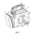
- FIG. 4shows a perspective view of a drainage pump device with a variation of a pump-side attachment part of the drainage tube unit according to the invention
- FIG. 5shows a perspective view of a variation of the pump housing with its seat for the pump-side attachment part
- FIG. 6shows a perspective view of the fluid collection container with its attachment opening for pluggable connection to the attachment part
- FIG. 7shows a perspective view of the drainage pump device shown in FIG. 4 , looking into the interior of the housing.
- FIG. 1shows a drainage tube unit as used in the drainage aspiration devices mentioned at the outset. It is composed mainly of a tube system 1 with two or more tubes 10 , 11 , a pump-side attachment part 2 and preferably, but not necessarily, a patient-side attachment part 3 . According to the invention, however, an individual single-lumen drainage tube can also be used.
- the tubes 10 , 11 shown hereare preferably single-lumen tubes independent of each other. They are preferably made of silicone or PVC. They extend separate from each other at their ends. Between the ends, they can be adhesively bonded to each other, welded to each other or otherwise connected. In the figures, the tubes are not shown at their full length and are instead interrupted.
- the two tubespreferably have different diameters.
- the thicker tube 10forms an underpressure and drainage line for aspirating the body fluid.
- the thinner tube 11forms a service line which, for example, permits the above-described or similar pressure measurement and/or cleaning of the drainage line. Both applications can be carried out jointly but one after the other if the suction unit at the pump-side end of the service line has a valve which is closed for the underpressure measurement during the aspiration procedure. During the cleaning mode, however, the valve is opened.
- the service linecan also be used in other known ways.
- the two tubes 10 , 11preferably extend parallel to each other along approximately the entire length, and their ends in particular open out in parallel, but spaced apart from each other, into the respective attachment parts or elements 2 , 3 . Spaced apart means that they can bear on each other or that they can leave a space free between them. At least in one of the two parts, they protrude inwards on the same face of the attachment part. The ends are inserted into the attachment parts 2 , 3 , adhesively bonded in them or otherwise secured.
- Pump-sidein this context, however, simply means remote from the patient.
- the attachment partcan instead also be arranged in a fluid collection container or other unit remote from the patient. Therefore, where the term pump-side is used below, this also means the container side.
- the pump-side attachment part 2is preferably made of plastic by injection moulding, and it is preferably designed in one piece.
- the part 2has a substantially cuboid main body 2 , which is here provided with a peripheral flange 21 . With this flange 21 , the part 2 can be introduced with a form fit into a corresponding recess of the pump housing and held therein, as is shown in FIG. 4 .
- the attachment part 2has two channels 24 , 25 , and the pump-side ends of the drainage and service tubes 10 , 11 are inserted into the mouth openings that lie parallel to each other but spaced apart from each other.
- a filter 6is preferably arranged in the pump-side service channel 25 .
- Thisfor example, is a hydrophobic filter and/or a bacterial filter.
- the service channel 25then narrows and bends off at right angles with respect to the mouth. It ends in a service inlet 23 that protrudes in the form of a connector piece from the main body 22 .
- This service inlet 23serves for connection to a service unit of the suction device.
- the pump-side drainage channel 24also bends off at right angles with respect to its mouth and likewise ends in a connector piece, the pump-side drainage outlet 20 , protruding from the main body 22 .
- This outlet 20serves for connection to a fluid collection container.
- the outlet 20is here arranged at right angles to the mouth of the tube 10 , but it can also be arranged on a different face of the main body 22 than the mouth face. The same applies for the service inlet 23 in relation to the mouth of the service tube 10 .
- the aspirated fluidpasses through the drainage outlet 20 into the container.
- a peripheral groovecan be provided round the drainage outlet 20 in the main body 22 .
- the groovecan be provided with a sealing ring.
- the drainage outlet 20is preferably arranged on a face of the main body 22 that lies opposite the face with the service inlet 23 .
- a more simply configured partcan also be used that is held on or in the pump housing 4 .
- the service channel and the service attachmentscan be dispensed with if only an individual drainage tube and no service tubes are to be attached.
- a patient-side attachment part 3On the patient side, it is possible, but not necessary, for a patient-side attachment part 3 to be present. If it is present, it is preferably also made of plastic by injection moulding. It too is preferably designed in one piece. A variant with a service tube is described below. It goes without saying that the part has a simpler design, particularly without connection channel and service channel, if no service channel is to be connected, but instead only an individual drainage tube.
- the patient-side attachment part 3has a main body 30 with two mouths for the patient-side ends of the drainage tube 10 and of the service tube 11 , which mouths are parallel to each other but spaced apart from each other.
- a patient-side drainage inlet 31formed integrally on this main body 30 , has a conical shape and is provided with steps and narrows towards its free end. It has a Christmas tree shape in cross section.
- the drainage inlet 31preferably extends approximately in axial alignment with the mouth of the patient-side end of the drainage tube 10 , such that the patient-side drainage channel 37 in the interior of the attachment part extends approximately in a straight line.
- the patient-side end of the service tube 11opens into a mouth of a patient-side service channel 35 , which preferably has a smaller diameter than the drainage channel 37 .
- the channel 37also like all the other channels described, has a step that serves as an abutment for the tube 11 .
- the mouths described aboveare understood as extending as far as these steps.
- connection channel 36ends in the main body 30 and there opens into a connection channel 36 , which is preferably perpendicular to the service channel 23 .
- the connection channel 36has the same diameter as or preferably a smaller diameter than the service channel 35 . It terminates at one end in a right-angled bend in the drainage channel 37 , preferably at the step to the mouth. Its other end forms an opening 34 to the outside, which opening 34 is preferably arranged perpendicular to the mouths in the main body 30 .
- This opening 34is closed by a sealing closure 32 , in this case a stopper.
- a sealing closure 32in this case a stopper.
- itis shown still in the open state, it is preferably already closed in this configuration, In fact it is preferably already closed on ejection from the injection moulding machine, that is to say long before the tubes 10 , 11 are secured.
- the sealing closure 32is preferably produced in one piece with the rest of the attachment part 3 and, as is shown, is therefore connected to the main body 30 via a band 33 . This opening permits the one-piece production of this attachment part.
- FIG. 4shows a drainage pump device with which the drainage tube unit is preferably used. It serves to aspirate body liquids or fluids in the medical field, for example during or after surgical interventions, but also for wound drainage, thorax drainage, or for liposuction.
- the tube unitcan also be used in other drainage pump devices. It is preferable, but not essential, that the fluid collection container and, in the case of service tubes, also the pump unit can be connected to each other by means of the pump-side attachment part 2 without further intermediate lines.
- the drainage pump device shown herehas a pump housing 4 which accommodates a vacuum pump or suction pump 60 , as shown in FIG. 7 , and electronics for operating the pump and for evaluating measured values obtained by way of the service tube.
- the pump housing 4preferably has a cuboid shape with a front wall 40 , a rear wall 41 , a handle 42 and feet 46 .
- On an upper face of the housing 4there is an operating panel 45 for operating the pump, preferably with a display.
- This fluid collection container 5is preferably composed of two container halves 50 , 51 and is made of a transparent plastic.
- the container 5can be secured releasably on the pump housing 4 , preferably being swiveled in and engaged in this position.
- the front wall 40 and the rear wall 41 of the pump housing 4have upper and lower slide guides in which upper and lower securing pins 52 of the container 5 engage. Only one upper pin can be seen in the figure. The lower pins are already engaged, as can be seen from the oblique position of the container 5 .
- the container 5has a hook 53 which is directed towards the housing 4 and in which a flip switch 44 of the housing 4 engages with a corresponding projection. In this way, the container 5 is fixed releasably on the housing 4 .
- the flip switch 44comprises a hook 44 ′ which engages with a recess 53 ′ of the fluid collection container 5 shown in FIG. 6 .
- a suction connector 47is provided on the housing 4 . It has the shape of a nozzle, which engages in a corresponding opening of the container 5 . In this way, an underpressure can be generated in the container 5 by means of the suction pump.
- the housing 4also has a substantially cuboid recess 49 into which the pump-side attachment part 2 of the drainage tube unit can be inserted and is held releasably therein with a form fit.
- the recess 48comprises plane side walls, so that the pump-side attachment part should comprise, contrary to the attachment part shown in FIGS. 1 to 3 , plane side walls as well.
- the recess 49comprises two plane and parallel to each other extending side walls and a curved, concave side wall connecting these two.
- This recess 49matches the embodiment according to FIGS. 1 to 3 .
- the container-side drainage outlet 20 of the attachment part 2 of both variantsis oriented towards the container 5 . Through it the aspirated fluid passes into the container 5 .
- the fluid collection container 5has a corresponding attachment opening 54 .
- the attachment part 2can also be provided with an opening and the fluid collection container can be provided with a connector piece that matches said opening.
- a sealed connectionis established, with a sealing means preferably being provided on at least one side, i.e. on the side of the attachment part or on the side of the fluid collection container.
- the sealing meansis preferably a sealing ring made of an elastomer material.
- itis an elastomer sealing ring 7 as shown in FIG. 3 .
- other known ways of making a plug-type connection air-tight and liquid-tightare possible.
- the tube system 1 with the two tubes 10 , 11opens into the pump-side attachment part 2 .
- the tube system 1 in this exampleis routed along the housing 4 in a channel 420 arranged on the handle 42 .
- the pump housing 4has a service opening 48 for receiving the service inlet 23 of the pump-side attachment part 2 .
- the service inlet 23 of the attachment part 2protrudes into the pump housing 4 and is connected to a corresponding control and/or evaluation unit.
- an air-tight or liquid-tight connectionis also present here.
- connector piece and openingcan be provided the other way round.
- the pump-side attachment partcan be inserted in the housing or held on the latter at another place.
- the attachmentscan, for example, be at another angle to one another.
- the pump-side attachment partcan be designed, for example, with a conical, cylindrical or other suitable shape.
- the drainage pump unit according to the inventionallows the fluid collection container to be replaced or emptied without removing the drainage tube and, therefore, without disturbing the patient.
Landscapes
- Health & Medical Sciences (AREA)
- Heart & Thoracic Surgery (AREA)
- Hematology (AREA)
- Anesthesiology (AREA)
- Biomedical Technology (AREA)
- Engineering & Computer Science (AREA)
- Life Sciences & Earth Sciences (AREA)
- Animal Behavior & Ethology (AREA)
- General Health & Medical Sciences (AREA)
- Public Health (AREA)
- Veterinary Medicine (AREA)
- Vascular Medicine (AREA)
- Otolaryngology (AREA)
- External Artificial Organs (AREA)
- Orthopedics, Nursing, And Contraception (AREA)
Abstract
Description
- 1 tube system
- 10 drainage tube
- 11 service tube
- 2 pump-side attachment part
- 20 pump-side drainage outlet
- 21 flange
- 22 main body
- 23 pump-side service inlet
- 24 pump-side drainage channel
- 25 pump-side service channel
- 3 patient-side attachment part
- 30 main body
- 31 patient-side drainage inlet
- 32 sealing cover
- 33 band
- 34 opening
- 35 patient-side service channel
- 36 connection channel
- 37 patient-side drainage channel
- 4 pump housing
- 40 front wall
- 41 rear wall
- 42 handle
- 420 channel
- 43 slide guide
- 44 flip switch
- 44′ hook
- 45 operating panel
- 46 foot
- 47 suction connector
- 48 service inlet
- 49 recess
- 5 fluid collection container
- 50 first half of container
- 51 second half of container
- 52 securing pin
- 53 hook
- 53′ recess
- 54 attachment opening
- 6 filter
- 7 sealing ring
- 60 suction pump assembly
Claims (13)
Applications Claiming Priority (3)
| Application Number | Priority Date | Filing Date | Title |
|---|---|---|---|
| CH8232007 | 2007-05-22 | ||
| CH823/07 | 2007-05-22 | ||
| PCT/CH2008/000225WO2008141471A1 (en) | 2007-05-22 | 2008-05-16 | Drainage pump unit |
Publications (2)
| Publication Number | Publication Date |
|---|---|
| US20100174227A1 US20100174227A1 (en) | 2010-07-08 |
| US8535284B2true US8535284B2 (en) | 2013-09-17 |
Family
ID=38512449
Family Applications (2)
| Application Number | Title | Priority Date | Filing Date |
|---|---|---|---|
| US12/598,841Active2030-06-08US8491550B2 (en) | 2007-05-22 | 2008-05-16 | Drainage tube unit |
| US12/300,983Active2029-07-19US8535284B2 (en) | 2007-05-22 | 2008-05-16 | Drainage pump unit |
Family Applications Before (1)
| Application Number | Title | Priority Date | Filing Date |
|---|---|---|---|
| US12/598,841Active2030-06-08US8491550B2 (en) | 2007-05-22 | 2008-05-16 | Drainage tube unit |
Country Status (14)
| Country | Link |
|---|---|
| US (2) | US8491550B2 (en) |
| EP (2) | EP2152334B1 (en) |
| JP (2) | JP5634863B2 (en) |
| KR (2) | KR101503757B1 (en) |
| CN (2) | CN101678201B (en) |
| AR (2) | AR066654A1 (en) |
| AU (2) | AU2008253526B2 (en) |
| BR (2) | BRPI0810321A2 (en) |
| CA (2) | CA2685991C (en) |
| ES (1) | ES2569069T5 (en) |
| PL (1) | PL2146774T3 (en) |
| RU (2) | RU2474442C2 (en) |
| TW (2) | TWI503136B (en) |
| WO (2) | WO2008141470A1 (en) |
Cited By (41)
| Publication number | Priority date | Publication date | Assignee | Title |
|---|---|---|---|---|
| WO2017194383A1 (en) | 2016-05-11 | 2017-11-16 | Medela Holding Ag | Diaphragm vacuum pump |
| US10219814B2 (en) | 2013-12-13 | 2019-03-05 | Rex Medical, L.P. | Aspiration system for thrombectomy procedures |
| US10702634B2 (en) | 2014-09-29 | 2020-07-07 | Centese, Inc. | Devices and methods for managing chest drainage |
| USD967409S1 (en) | 2020-07-15 | 2022-10-18 | Purewick Corporation | Urine collection apparatus cover |
| US11529252B2 (en) | 2018-05-01 | 2022-12-20 | Purewick Corporation | Fluid collection garments |
| US11628086B2 (en) | 2016-07-27 | 2023-04-18 | Purewick Corporation | Apparatus and methods for receiving discharged urine |
| US11801186B2 (en) | 2020-09-10 | 2023-10-31 | Purewick Corporation | Urine storage container handle and lid accessories |
| US11806266B2 (en) | 2014-03-19 | 2023-11-07 | Purewick Corporation | Apparatus and methods for receiving discharged urine |
| US11865030B2 (en) | 2021-01-19 | 2024-01-09 | Purewick Corporation | Variable fit fluid collection devices, systems, and methods |
| US11925575B2 (en) | 2021-02-26 | 2024-03-12 | Purewick Corporation | Fluid collection devices having a sump between a tube opening and a barrier, and related systems and methods |
| US11938053B2 (en) | 2018-05-01 | 2024-03-26 | Purewick Corporation | Fluid collection devices, systems, and methods |
| US11944740B2 (en) | 2018-05-01 | 2024-04-02 | Purewick Corporation | Fluid collection devices, related systems, and related methods |
| US12029677B2 (en) | 2021-04-06 | 2024-07-09 | Purewick Corporation | Fluid collection devices having a collection bag, and related systems and methods |
| US12029678B2 (en) | 2016-07-27 | 2024-07-09 | Purewick Corporation | Male urine collection device using wicking material |
| US12042423B2 (en) | 2020-10-07 | 2024-07-23 | Purewick Corporation | Fluid collection systems including at least one tensioning element |
| US12048644B2 (en) | 2020-11-03 | 2024-07-30 | Purewick Corporation | Apparatus for receiving discharged urine |
| US12048643B2 (en) | 2020-05-27 | 2024-07-30 | Purewick Corporation | Fluid collection assemblies including at least one inflation device and methods and systems of using the same |
| US12070432B2 (en) | 2020-11-11 | 2024-08-27 | Purewick Corporation | Urine collection system including a flow meter and related methods |
| US12121468B2 (en) | 2014-03-19 | 2024-10-22 | Purewick Corporation | Apparatus and methods for receiving discharged urine |
| US12138196B2 (en) | 2014-03-19 | 2024-11-12 | Purewick Corporation | Apparatus and methods for receiving discharged urine |
| US12138195B2 (en) | 2020-04-10 | 2024-11-12 | Purewick Corporation | Fluid collection assemblies including one or more leak prevention features |
| US12150885B2 (en) | 2021-05-26 | 2024-11-26 | Purewick Corporation | Fluid collection system including a cleaning system and methods |
| US12156792B2 (en) | 2020-09-10 | 2024-12-03 | Purewick Corporation | Fluid collection assemblies including at least one inflation device |
| US12161579B2 (en) | 2014-03-19 | 2024-12-10 | Purewick Corporation | Apparatus and methods for receiving discharged urine |
| US12178735B2 (en) | 2021-02-09 | 2024-12-31 | Purewick Corporation | Noise reduction for a urine suction system |
| US12193962B2 (en) | 2016-06-02 | 2025-01-14 | Purewick Corporation | Using wicking material to collect liquid for transport |
| US12208031B2 (en) | 2020-10-21 | 2025-01-28 | Purewick Corporation | Adapters for fluid collection devices |
| US12233003B2 (en) | 2021-04-29 | 2025-02-25 | Purewick Corporation | Fluid collection assemblies including at least one length adjusting feature |
| US12245967B2 (en) | 2020-11-18 | 2025-03-11 | Purewick Corporation | Fluid collection assemblies including an adjustable spine |
| US12251333B2 (en) | 2021-05-21 | 2025-03-18 | Purewick Corporation | Fluid collection assemblies including at least one inflation device and methods and systems of using the same |
| US12257173B2 (en) | 2017-01-31 | 2025-03-25 | Purewick Corporation | Apparatus and methods for receiving discharged urine |
| US12257174B2 (en) | 2020-10-21 | 2025-03-25 | Purewick Corporation | Fluid collection assemblies including at least one of a protrusion or at least one expandable material |
| US12268627B2 (en) | 2021-01-06 | 2025-04-08 | Purewick Corporation | Fluid collection assemblies including at least one securement body |
| US12274638B2 (en) | 2018-05-01 | 2025-04-15 | Purewick Corporation | Fluid collection devices, related systems, and related methods |
| US12295876B2 (en) | 2018-05-01 | 2025-05-13 | Purewick Corporation | Fluid collection devices and methods of using the same |
| US12324767B2 (en) | 2021-05-24 | 2025-06-10 | Purewick Corporation | Fluid collection assembly including a customizable external support and related methods |
| US12329364B2 (en) | 2019-07-19 | 2025-06-17 | Purewick Corporation | Fluid collection devices including at least one shape memory material |
| US12350190B2 (en) | 2020-01-03 | 2025-07-08 | Purewick Corporation | Urine collection devices having a relatively wide portion and an elongated portion and related methods |
| US12350187B2 (en) | 2020-08-11 | 2025-07-08 | Purewick Corporation | Fluid collection assemblies defining waist and leg openings |
| US12419778B2 (en) | 2019-06-21 | 2025-09-23 | Purewick Corporation | Fluid collection devices including a base securement area, and related systems and methods |
| US12440371B2 (en) | 2021-08-05 | 2025-10-14 | Purewick Corporation | Fluid collection system including a garment and a fluid collection device |
Families Citing this family (63)
| Publication number | Priority date | Publication date | Assignee | Title |
|---|---|---|---|---|
| GB0224986D0 (en) | 2002-10-28 | 2002-12-04 | Smith & Nephew | Apparatus |
| US11298453B2 (en) | 2003-10-28 | 2022-04-12 | Smith & Nephew Plc | Apparatus and method for wound cleansing with actives |
| GB0508531D0 (en) | 2005-04-27 | 2005-06-01 | Smith & Nephew | Sai with ultrasound |
| EP1905465B2 (en) | 2006-09-28 | 2013-11-27 | Smith & Nephew, Inc. | Portable wound therapy system |
| CN101678201B (en)* | 2007-05-22 | 2012-12-26 | 美德乐控股公司 | Drainage tube unit |
| GB0715212D0 (en)* | 2007-08-06 | 2007-09-12 | Smith & Nephew | Apparatus |
| GB0722820D0 (en) | 2007-11-21 | 2008-01-02 | Smith & Nephew | Vacuum assisted wound dressing |
| WO2009067711A2 (en) | 2007-11-21 | 2009-05-28 | T.J. Smith & Nephew, Limited | Suction device and dressing |
| ES2715605T3 (en) | 2007-11-21 | 2019-06-05 | Smith & Nephew | Wound dressing |
| GB0723876D0 (en) | 2007-12-06 | 2008-01-16 | Smith & Nephew | Apparatus and method for topical negative pressure therapy |
| US20130096518A1 (en) | 2007-12-06 | 2013-04-18 | Smith & Nephew Plc | Wound filling apparatuses and methods |
| GB0723875D0 (en) | 2007-12-06 | 2008-01-16 | Smith & Nephew | Wound management |
| GB0723872D0 (en) | 2007-12-06 | 2008-01-16 | Smith & Nephew | Apparatus for topical negative pressure therapy |
| US11253399B2 (en) | 2007-12-06 | 2022-02-22 | Smith & Nephew Plc | Wound filling apparatuses and methods |
| US8021347B2 (en) | 2008-07-21 | 2011-09-20 | Tyco Healthcare Group Lp | Thin film wound dressing |
| US9033942B2 (en) | 2008-03-07 | 2015-05-19 | Smith & Nephew, Inc. | Wound dressing port and associated wound dressing |
| US8298200B2 (en) | 2009-06-01 | 2012-10-30 | Tyco Healthcare Group Lp | System for providing continual drainage in negative pressure wound therapy |
| ES2658263T3 (en) | 2008-08-08 | 2018-03-09 | Smith & Nephew, Inc. | Continuous fiber wound dressing |
| US8162907B2 (en) | 2009-01-20 | 2012-04-24 | Tyco Healthcare Group Lp | Method and apparatus for bridging from a dressing in negative pressure wound therapy |
| US20100324516A1 (en) | 2009-06-18 | 2010-12-23 | Tyco Healthcare Group Lp | Apparatus for Vacuum Bridging and/or Exudate Collection |
| CH702195A1 (en) | 2009-11-05 | 2011-05-13 | Medela Holding Ag | Drainage pump unit |
| AU2010341491B2 (en) | 2009-12-22 | 2015-05-14 | Smith & Nephew, Inc. | Apparatuses and methods for negative pressure wound therapy |
| US8801684B2 (en) | 2010-02-16 | 2014-08-12 | Medela Holding Ag | Coupling part of a drainage tube unit |
| CH702752A1 (en)* | 2010-02-16 | 2011-08-31 | Medela Holding Ag | Coupling part of a drainage tube unit. |
| USRE48117E1 (en) | 2010-05-07 | 2020-07-28 | Smith & Nephew, Inc. | Apparatuses and methods for negative pressure wound therapy |
| US9622670B2 (en) | 2010-07-09 | 2017-04-18 | Potrero Medical, Inc. | Method and apparatus for pressure measurement |
| WO2012033906A2 (en) | 2010-09-09 | 2012-03-15 | University Of Florida Research Foundation Inc. | Context-sensitive flow interrupter and drainage outflow optimization system |
| CA140188S (en) | 2010-10-15 | 2011-11-07 | Smith & Nephew | Medical dressing |
| CA140189S (en) | 2010-10-15 | 2011-11-07 | Smith & Nephew | Medical dressing |
| RU2016111981A (en) | 2010-12-22 | 2018-11-27 | Смит Энд Нефью, Инк. | DEVICE AND METHOD FOR TREATING RAS WITH NEGATIVE PRESSURE |
| USD714433S1 (en) | 2010-12-22 | 2014-09-30 | Smith & Nephew, Inc. | Suction adapter |
| CH704423A1 (en) | 2011-01-17 | 2012-07-31 | Medela Holding Ag | Drainage pump unit. |
| US9662058B2 (en) | 2011-03-07 | 2017-05-30 | Potrero Medical, Inc. | Sensing Foley catheter |
| CH705248A1 (en) | 2011-07-07 | 2013-01-15 | Medela Holding Ag | Thoracic drainage device with reduced backpressure. |
| TWI569788B (en)* | 2011-11-22 | 2017-02-11 | 優你 嬌美股份有限公司 | Disposable disposable diaper |
| JP6400570B2 (en) | 2012-05-23 | 2018-10-10 | スミス アンド ネフュー ピーエルシーSmith & Nephew Public Limited Company | Apparatus and method for local negative pressure closure therapy |
| CN108186200B (en) | 2012-08-01 | 2021-08-10 | 史密夫及内修公开有限公司 | Wound dressing |
| WO2014020440A1 (en) | 2012-08-01 | 2014-02-06 | Smith & Nephew Plc | Wound dressing |
| CH707857A1 (en) | 2013-04-02 | 2014-10-15 | Medela Holding Ag | Device with a flow channel. |
| US10010658B2 (en) | 2013-05-10 | 2018-07-03 | Smith & Nephew Plc | Fluidic connector for irrigation and aspiration of wounds |
| KR101496209B1 (en)* | 2013-05-25 | 2015-02-26 | 서현배 | Electronic aspirator |
| JP6634661B2 (en) | 2014-01-07 | 2020-01-22 | ポトレロ メディカル,インコーポレイテッド | Systems, instruments and methods for draining and analyzing body fluids |
| EP3096824A1 (en) | 2014-01-24 | 2016-11-30 | Cole Research&Design, Inc. | Oral suction device |
| US11090183B2 (en) | 2014-11-25 | 2021-08-17 | Purewick Corporation | Container for collecting liquid for transport |
| EP2959926A1 (en) | 2014-06-26 | 2015-12-30 | Medela Holding AG | Medical suction pump and fluid-collection container |
| SG11201701818YA (en) | 2014-09-28 | 2017-04-27 | Potrero Medical Inc | Systems, devices and methods for sensing physiologic data and draining and analyzing bodily fluids |
| KR20160105709A (en) | 2015-02-28 | 2016-09-07 | 서현배 | Indirect suction type portable aspirator |
| KR20160115619A (en) | 2015-03-28 | 2016-10-06 | 서현배 | Indirect suction type vacuum drainage system |
| US10076594B2 (en) | 2015-05-18 | 2018-09-18 | Smith & Nephew Plc | Fluidic connector for negative pressure wound therapy |
| WO2017007660A1 (en)* | 2015-07-03 | 2017-01-12 | Merit Medical Systems, Inc. | Devices and methods for fluid infusion, drainage and collection |
| US10391275B2 (en) | 2015-11-17 | 2019-08-27 | Potrero Medical, Inc. | Systems, devices and methods for draining and analyzing bodily fluids |
| CN115054413A (en) | 2016-09-29 | 2022-09-16 | 美国医疗设备有限公司 | Method of adjusting effective length of stent and prosthesis delivery catheter assembly |
| EP4467111A3 (en) | 2017-03-15 | 2025-03-05 | Merit Medical Systems, Inc. | Transluminal stents |
| GB201718014D0 (en) | 2017-11-01 | 2017-12-13 | Smith & Nephew | Dressing for negative pressure wound therapy with filter |
| GB201811449D0 (en) | 2018-07-12 | 2018-08-29 | Smith & Nephew | Apparatuses and methods for negative pressure wound therapy |
| CN111214750A (en)* | 2019-12-03 | 2020-06-02 | 徐州辉眸医疗科技有限公司 | Medical drainage tube |
| GB202000574D0 (en) | 2020-01-15 | 2020-02-26 | Smith & Nephew | Fluidic connectors for negative pressure wound therapy |
| KR102458412B1 (en)* | 2021-01-15 | 2022-10-25 | 연세대학교 산학협력단 | Device for checking intrathoracic pressure and device for inserting thoracic cavity included therein |
| CN112545773B (en)* | 2021-01-25 | 2021-11-26 | 哈尔滨医科大学 | Novel clinical medicine first aid is supplementary device |
| CN112915301A (en)* | 2021-03-03 | 2021-06-08 | 周义龙 | Multifunctional medical drainage and flushing device and operation method thereof |
| US11938054B2 (en) | 2021-03-10 | 2024-03-26 | Purewick Corporation | Bodily waste and fluid collection with sacral pad |
| KR102602742B1 (en) | 2023-06-19 | 2023-11-14 | 백영진 | Nasal catheter to prevent negative pressure |
| KR102832129B1 (en)* | 2025-01-23 | 2025-07-09 | 최형찬 | Apparatus for suctioning and exhausting surgery cleaning liquid |
Citations (20)
| Publication number | Priority date | Publication date | Assignee | Title |
|---|---|---|---|---|
| US3957052A (en) | 1974-09-13 | 1976-05-18 | Medical Development Corporation | Pumping-syringe |
| US4883476A (en) | 1988-01-07 | 1989-11-28 | Bioresearch, Inc. | Drainage device with disposable collection chamber |
| US5466229A (en)* | 1993-08-06 | 1995-11-14 | Davstar, Inc. | Fluid collection system |
| WO1996005873A1 (en) | 1994-08-22 | 1996-02-29 | Kinetic Concepts Inc. | Wound drainage equipment |
| US5507734A (en) | 1986-10-07 | 1996-04-16 | Deknatel Technology Corporation | Drainage device |
| GB2307180A (en) | 1995-11-14 | 1997-05-21 | Kci Medical Ltd | Portable pump for draining fluid from a wound dressing |
| WO1998030270A1 (en) | 1997-01-07 | 1998-07-16 | C.R. Bard, Inc. | System for aspirating and irrigating tract wounds |
| DE29911438U1 (en) | 1999-07-01 | 2000-12-21 | Madaus AG, 51109 Köln | Suction device for body fluids, especially for secretions in the trachea |
| US20010031943A1 (en) | 2000-03-03 | 2001-10-18 | Urie Robert Graham | Apparatus for assisting wound healing |
| US6352525B1 (en) | 1999-09-22 | 2002-03-05 | Akio Wakabayashi | Portable modular chest drainage system |
| EP1184043A1 (en) | 2000-08-28 | 2002-03-06 | Medela AG | Mini suction pump |
| US6358218B1 (en) | 1999-01-29 | 2002-03-19 | Atrium Medical Corporation | Fluid-recovery system with integrally molded components |
| US20020161317A1 (en) | 1999-11-29 | 2002-10-31 | Risk James R. | Wound treatment apparatus |
| GB2378734A (en) | 2001-08-14 | 2003-02-19 | Carmeli Adahan | Disposable pump with detachable motor |
| US20030163101A1 (en) | 2002-02-28 | 2003-08-28 | Say Samuel L. | Portable battery operated aspirator |
| US20040024360A1 (en) | 2000-08-28 | 2004-02-05 | Andy Greter | Suction pump |
| WO2005061025A1 (en) | 2003-12-22 | 2005-07-07 | Medela Holding Ag | Drainage apparatus and method |
| US20050171495A1 (en) | 2004-01-29 | 2005-08-04 | Austin Timothy W. | Waste collection unit with manifold interface assembly |
| US20060036221A1 (en) | 2004-08-10 | 2006-02-16 | Watson Richard L Jr | Chest tube drainage system |
| WO2007128156A2 (en) | 2006-05-09 | 2007-11-15 | Medela Holding Ag | Suction pump unit |
Family Cites Families (27)
| Publication number | Priority date | Publication date | Assignee | Title |
|---|---|---|---|---|
| US635252A (en)* | 1891-09-30 | 1899-10-17 | Lyman D Howard | Electric railway. |
| US3749090A (en) | 1971-06-09 | 1973-07-31 | Stewart Research | Combination aspirator and fluid delivering surgical instrument |
| US3889675A (en) | 1974-06-25 | 1975-06-17 | Stewart Research | Suction-irrigator |
| JPS6069139U (en)* | 1983-10-19 | 1985-05-16 | 住友ベークライト株式会社 | medical catheter |
| JP2676344B2 (en) | 1987-07-13 | 1997-11-12 | 日本サ−ボ株式会社 | Multi-phase linear stepping motor |
| US5101817A (en) | 1989-08-04 | 1992-04-07 | Nellcor, Inc. | Airway adapter for use with closed suction catheter system |
| US5140983A (en)* | 1990-04-11 | 1992-08-25 | Jinotti Walter J | Multi purpose catheter assembly |
| US5029580A (en) | 1990-07-18 | 1991-07-09 | Ballard Medical Products | Medical aspirating apparatus with multi-lumen catheter tube and methods |
| JP3123750B2 (en)* | 1990-11-13 | 2001-01-15 | 株式会社ニデック | Perfusion suction device |
| US5134996A (en) | 1991-01-09 | 1992-08-04 | Smiths Industries Medical Systems, Inc. | Inspiration and expiration indicator for a suction catheter |
| DK8391A (en)* | 1991-01-18 | 1992-07-19 | Uno Plast As | Suction pump for use in extraction of body fluids from the body cavity |
| US5370610A (en)* | 1993-02-09 | 1994-12-06 | Reynolds; James R. | Surgical drainage tube system |
| DE4306478A1 (en) | 1993-03-02 | 1994-09-08 | Wolfgang Dr Wagner | Drainage device, in particular pleural drainage device, and drainage method |
| US5462522A (en) | 1993-04-19 | 1995-10-31 | Olympus Optical Co., Ltd. | Ultrasonic therapeutic apparatus |
| US6261276B1 (en)* | 1995-03-13 | 2001-07-17 | I.S.I. International, Inc. | Apparatus for draining surgical wounds |
| US6200292B1 (en) | 1996-06-18 | 2001-03-13 | C. R. Bard, Inc. | Suction and irrigation handpiece and tip |
| ATE288769T1 (en) | 1997-02-26 | 2005-02-15 | Medela Ag | DEVICE FOR SUCTION OF LIQUIDS |
| DE19913713C2 (en) | 1999-03-26 | 2001-04-12 | Heraeus Med Gmbh | Plug connection, especially for suction devices |
| FI116200B (en) | 1999-10-01 | 2005-10-14 | Serres Oy | Sugpåseanordning |
| GB9926538D0 (en) | 1999-11-09 | 2000-01-12 | Kci Medical Ltd | Multi-lumen connector |
| US6626827B1 (en) | 2000-09-01 | 2003-09-30 | C. R. Bard, Inc. | Fluid management assembly for use in endoscopic procedures |
| AU2002359828A1 (en) | 2001-12-26 | 2003-07-24 | Hill-Rom Services Inc. | Vented vacuum bandage and method |
| US7163531B2 (en)* | 2002-08-19 | 2007-01-16 | Baxter International, Inc. | User-friendly catheter connection adapters for optimized connection to multiple lumen catheters |
| FR2853836B1 (en) | 2003-04-16 | 2006-01-06 | Crossject | NEEDLELESS SYRINGE WITH OPTIMIZED INJECTOR-RECEPTACLE |
| US6883347B2 (en)† | 2003-09-23 | 2005-04-26 | Zahid Hussain Ayub | End bonnets for shell and tube DX evaporator |
| RU2283000C2 (en)* | 2003-11-19 | 2006-09-10 | Центр "Биоинженерия" Ран | Method for protein production |
| CN101678201B (en)* | 2007-05-22 | 2012-12-26 | 美德乐控股公司 | Drainage tube unit |
- 2008
- 2008-05-16CNCN2008800170039Apatent/CN101678201B/enactiveActive
- 2008-05-16USUS12/598,841patent/US8491550B2/enactiveActive
- 2008-05-16PLPL08748354Tpatent/PL2146774T3/enunknown
- 2008-05-16CACA2685991Apatent/CA2685991C/enactiveActive
- 2008-05-16BRBRPI0810321-6A2Apatent/BRPI0810321A2/ennot_activeApplication Discontinuation
- 2008-05-16JPJP2010508686Apatent/JP5634863B2/enactiveActive
- 2008-05-16EPEP08748355.8Apatent/EP2152334B1/enactiveActive
- 2008-05-16CNCN2008800170217Apatent/CN101678157B/enactiveActive
- 2008-05-16ESES08748354.1Tpatent/ES2569069T5/enactiveActive
- 2008-05-16AUAU2008253526Apatent/AU2008253526B2/enactiveActive
- 2008-05-16WOPCT/CH2008/000224patent/WO2008141470A1/enactiveApplication Filing
- 2008-05-16RURU2009145030/14Apatent/RU2474442C2/ennot_activeIP Right Cessation
- 2008-05-16EPEP08748354.1Apatent/EP2146774B2/enactiveActive
- 2008-05-16USUS12/300,983patent/US8535284B2/enactiveActive
- 2008-05-16CACA2684148Apatent/CA2684148C/enactiveActive
- 2008-05-16KRKR1020097022547Apatent/KR101503757B1/enactiveActive
- 2008-05-16JPJP2010508685Apatent/JP5314006B2/enactiveActive
- 2008-05-16AUAU2008253527Apatent/AU2008253527B2/enactiveActive
- 2008-05-16WOPCT/CH2008/000225patent/WO2008141471A1/enactiveApplication Filing
- 2008-05-16BRBRPI0810289-9Apatent/BRPI0810289A2/ennot_activeApplication Discontinuation
- 2008-05-16KRKR1020097024323Apatent/KR101494349B1/enactiveActive
- 2008-05-16RURU2009145028/14Apatent/RU2474436C2/ennot_activeIP Right Cessation
- 2008-05-20TWTW097118471Apatent/TWI503136B/ennot_activeIP Right Cessation
- 2008-05-21ARARP080102144Apatent/AR066654A1/ennot_activeApplication Discontinuation
- 2008-05-21TWTW097118646Apatent/TWI481427B/ennot_activeIP Right Cessation
- 2008-05-21ARARP080102145Apatent/AR066655A1/ennot_activeApplication Discontinuation
Patent Citations (27)
| Publication number | Priority date | Publication date | Assignee | Title |
|---|---|---|---|---|
| US3957052A (en) | 1974-09-13 | 1976-05-18 | Medical Development Corporation | Pumping-syringe |
| US5507734A (en) | 1986-10-07 | 1996-04-16 | Deknatel Technology Corporation | Drainage device |
| US4883476A (en) | 1988-01-07 | 1989-11-28 | Bioresearch, Inc. | Drainage device with disposable collection chamber |
| US5466229A (en)* | 1993-08-06 | 1995-11-14 | Davstar, Inc. | Fluid collection system |
| WO1996005873A1 (en) | 1994-08-22 | 1996-02-29 | Kinetic Concepts Inc. | Wound drainage equipment |
| EP1219311A2 (en) | 1994-08-22 | 2002-07-03 | Kinetic Concepts, Inc. | Canister |
| GB2307180A (en) | 1995-11-14 | 1997-05-21 | Kci Medical Ltd | Portable pump for draining fluid from a wound dressing |
| WO1998030270A1 (en) | 1997-01-07 | 1998-07-16 | C.R. Bard, Inc. | System for aspirating and irrigating tract wounds |
| JP2001507971A (en) | 1997-01-07 | 2001-06-19 | シー・アール・バード・インク | Device for suction and irrigation of tubular wounds |
| US6394996B1 (en) | 1997-01-07 | 2002-05-28 | C. R. Bard, Inc. | System for aspirating and irrigating tract wounds |
| US6358218B1 (en) | 1999-01-29 | 2002-03-19 | Atrium Medical Corporation | Fluid-recovery system with integrally molded components |
| DE29911438U1 (en) | 1999-07-01 | 2000-12-21 | Madaus AG, 51109 Köln | Suction device for body fluids, especially for secretions in the trachea |
| US6352525B1 (en) | 1999-09-22 | 2002-03-05 | Akio Wakabayashi | Portable modular chest drainage system |
| US20020058915A1 (en) | 1999-09-22 | 2002-05-16 | Akio Wakabayashi | Portable modular chest drainage system |
| US20020161317A1 (en) | 1999-11-29 | 2002-10-31 | Risk James R. | Wound treatment apparatus |
| US6755807B2 (en) | 1999-11-29 | 2004-06-29 | Hill-Rom Services, Inc. | Wound treatment apparatus |
| US20010031943A1 (en) | 2000-03-03 | 2001-10-18 | Urie Robert Graham | Apparatus for assisting wound healing |
| EP1184043A1 (en) | 2000-08-28 | 2002-03-06 | Medela AG | Mini suction pump |
| US20040024360A1 (en) | 2000-08-28 | 2004-02-05 | Andy Greter | Suction pump |
| US20040208756A1 (en) | 2001-08-14 | 2004-10-21 | Carmeli Adahan | Compact vacuum pump |
| GB2378734A (en) | 2001-08-14 | 2003-02-19 | Carmeli Adahan | Disposable pump with detachable motor |
| WO2003016719A1 (en) | 2001-08-14 | 2003-02-27 | Carmeli Adahan | A compact vacuum pump |
| US20030163101A1 (en) | 2002-02-28 | 2003-08-28 | Say Samuel L. | Portable battery operated aspirator |
| WO2005061025A1 (en) | 2003-12-22 | 2005-07-07 | Medela Holding Ag | Drainage apparatus and method |
| US20050171495A1 (en) | 2004-01-29 | 2005-08-04 | Austin Timothy W. | Waste collection unit with manifold interface assembly |
| US20060036221A1 (en) | 2004-08-10 | 2006-02-16 | Watson Richard L Jr | Chest tube drainage system |
| WO2007128156A2 (en) | 2006-05-09 | 2007-11-15 | Medela Holding Ag | Suction pump unit |
Non-Patent Citations (5)
| Title |
|---|
| English translation of the Int. Search Report and Written Opinion for International App. No. PCT/CH2007/000220, dated Dec. 4, 2008. |
| English translation of the Int. Search Report and Written Opinion for International App. No. PCT/CH2008/000225, completed Sep. 3, 2008. |
| English translation of the International Preliminary Report on Patentability for corresponding International App. No. PCT/CH2008/000225. |
| International Preliminary Report on Patentability for PCT/CH2007/000220 mailed on Dec. 10, 2008, issued Dec. 10, 2008. |
| International Search Report from European Application 09012685 mailed Dec. 11, 2009. |
Cited By (52)
| Publication number | Priority date | Publication date | Assignee | Title |
|---|---|---|---|---|
| US10219814B2 (en) | 2013-12-13 | 2019-03-05 | Rex Medical, L.P. | Aspiration system for thrombectomy procedures |
| US10772644B2 (en) | 2013-12-13 | 2020-09-15 | Rex Medical L.P. | Aspiration system for thrombectomy procedures |
| US12239567B2 (en) | 2014-03-19 | 2025-03-04 | Purewick Corporation | Apparatus and methods for receiving discharged urine |
| US12138196B2 (en) | 2014-03-19 | 2024-11-12 | Purewick Corporation | Apparatus and methods for receiving discharged urine |
| US12161579B2 (en) | 2014-03-19 | 2024-12-10 | Purewick Corporation | Apparatus and methods for receiving discharged urine |
| US12324765B2 (en) | 2014-03-19 | 2025-06-10 | Purewick Corporation | Apparatus and methods for receiving discharged urine |
| US12171685B2 (en) | 2014-03-19 | 2024-12-24 | Purewick Corporation | Apparatus and methods for receiving discharged urine |
| US11806266B2 (en) | 2014-03-19 | 2023-11-07 | Purewick Corporation | Apparatus and methods for receiving discharged urine |
| US12121468B2 (en) | 2014-03-19 | 2024-10-22 | Purewick Corporation | Apparatus and methods for receiving discharged urine |
| US11679196B2 (en) | 2014-09-29 | 2023-06-20 | Centese, Inc. | Devices and methods for managing chest drainage |
| US10702634B2 (en) | 2014-09-29 | 2020-07-07 | Centese, Inc. | Devices and methods for managing chest drainage |
| US11147909B2 (en) | 2016-05-11 | 2021-10-19 | Medela Holding Ag | Diaphragm vacuum pump |
| WO2017194383A1 (en) | 2016-05-11 | 2017-11-16 | Medela Holding Ag | Diaphragm vacuum pump |
| US12193962B2 (en) | 2016-06-02 | 2025-01-14 | Purewick Corporation | Using wicking material to collect liquid for transport |
| US11628086B2 (en) | 2016-07-27 | 2023-04-18 | Purewick Corporation | Apparatus and methods for receiving discharged urine |
| US12029678B2 (en) | 2016-07-27 | 2024-07-09 | Purewick Corporation | Male urine collection device using wicking material |
| US12257173B2 (en) | 2017-01-31 | 2025-03-25 | Purewick Corporation | Apparatus and methods for receiving discharged urine |
| US11944740B2 (en) | 2018-05-01 | 2024-04-02 | Purewick Corporation | Fluid collection devices, related systems, and related methods |
| US12295876B2 (en) | 2018-05-01 | 2025-05-13 | Purewick Corporation | Fluid collection devices and methods of using the same |
| US12274638B2 (en) | 2018-05-01 | 2025-04-15 | Purewick Corporation | Fluid collection devices, related systems, and related methods |
| US11529252B2 (en) | 2018-05-01 | 2022-12-20 | Purewick Corporation | Fluid collection garments |
| US12285352B2 (en) | 2018-05-01 | 2025-04-29 | Purewick Corporation | Fluid collection devices, systems, and methods |
| US11938053B2 (en) | 2018-05-01 | 2024-03-26 | Purewick Corporation | Fluid collection devices, systems, and methods |
| US12419778B2 (en) | 2019-06-21 | 2025-09-23 | Purewick Corporation | Fluid collection devices including a base securement area, and related systems and methods |
| US12329364B2 (en) | 2019-07-19 | 2025-06-17 | Purewick Corporation | Fluid collection devices including at least one shape memory material |
| US12350190B2 (en) | 2020-01-03 | 2025-07-08 | Purewick Corporation | Urine collection devices having a relatively wide portion and an elongated portion and related methods |
| US12138195B2 (en) | 2020-04-10 | 2024-11-12 | Purewick Corporation | Fluid collection assemblies including one or more leak prevention features |
| US12048643B2 (en) | 2020-05-27 | 2024-07-30 | Purewick Corporation | Fluid collection assemblies including at least one inflation device and methods and systems of using the same |
| USD967409S1 (en) | 2020-07-15 | 2022-10-18 | Purewick Corporation | Urine collection apparatus cover |
| US12350187B2 (en) | 2020-08-11 | 2025-07-08 | Purewick Corporation | Fluid collection assemblies defining waist and leg openings |
| US12156792B2 (en) | 2020-09-10 | 2024-12-03 | Purewick Corporation | Fluid collection assemblies including at least one inflation device |
| US11801186B2 (en) | 2020-09-10 | 2023-10-31 | Purewick Corporation | Urine storage container handle and lid accessories |
| US12042423B2 (en) | 2020-10-07 | 2024-07-23 | Purewick Corporation | Fluid collection systems including at least one tensioning element |
| US12208031B2 (en) | 2020-10-21 | 2025-01-28 | Purewick Corporation | Adapters for fluid collection devices |
| US12257174B2 (en) | 2020-10-21 | 2025-03-25 | Purewick Corporation | Fluid collection assemblies including at least one of a protrusion or at least one expandable material |
| US12048644B2 (en) | 2020-11-03 | 2024-07-30 | Purewick Corporation | Apparatus for receiving discharged urine |
| US12290485B2 (en) | 2020-11-11 | 2025-05-06 | Purewick Corporation | Urine collection system including a flow meter and related methods |
| US12070432B2 (en) | 2020-11-11 | 2024-08-27 | Purewick Corporation | Urine collection system including a flow meter and related methods |
| US12245967B2 (en) | 2020-11-18 | 2025-03-11 | Purewick Corporation | Fluid collection assemblies including an adjustable spine |
| US12268627B2 (en) | 2021-01-06 | 2025-04-08 | Purewick Corporation | Fluid collection assemblies including at least one securement body |
| US12186229B2 (en) | 2021-01-19 | 2025-01-07 | Purewick Corporation | Variable fit fluid collection devices, systems, and methods |
| US11865030B2 (en) | 2021-01-19 | 2024-01-09 | Purewick Corporation | Variable fit fluid collection devices, systems, and methods |
| US12178735B2 (en) | 2021-02-09 | 2024-12-31 | Purewick Corporation | Noise reduction for a urine suction system |
| US11925575B2 (en) | 2021-02-26 | 2024-03-12 | Purewick Corporation | Fluid collection devices having a sump between a tube opening and a barrier, and related systems and methods |
| US12245966B2 (en) | 2021-02-26 | 2025-03-11 | Purewick Corporation | Fluid collection devices having a sump between a tube opening and a barrier, and related systems and methods |
| US12029677B2 (en) | 2021-04-06 | 2024-07-09 | Purewick Corporation | Fluid collection devices having a collection bag, and related systems and methods |
| US12233003B2 (en) | 2021-04-29 | 2025-02-25 | Purewick Corporation | Fluid collection assemblies including at least one length adjusting feature |
| US12251333B2 (en) | 2021-05-21 | 2025-03-18 | Purewick Corporation | Fluid collection assemblies including at least one inflation device and methods and systems of using the same |
| US12324767B2 (en) | 2021-05-24 | 2025-06-10 | Purewick Corporation | Fluid collection assembly including a customizable external support and related methods |
| US12150885B2 (en) | 2021-05-26 | 2024-11-26 | Purewick Corporation | Fluid collection system including a cleaning system and methods |
| US12440371B2 (en) | 2021-08-05 | 2025-10-14 | Purewick Corporation | Fluid collection system including a garment and a fluid collection device |
| US12440370B2 (en) | 2021-10-19 | 2025-10-14 | Purewick Corporation | Apparatus with compressible casing for receiving discharged urine |
Also Published As
Similar Documents
| Publication | Publication Date | Title |
|---|---|---|
| US8535284B2 (en) | Drainage pump unit | |
| US8529530B2 (en) | Drainage pump unit | |
| US8801684B2 (en) | Coupling part of a drainage tube unit | |
| EP3110465B1 (en) | Aspirators | |
| US9700378B2 (en) | Endoscope lens cleaning device | |
| KR101787707B1 (en) | Coupling part of a drainage tube unit | |
| US10617798B2 (en) | Device for aspirating and transferring blood | |
| HK1136791B (en) | Drainage tube unit |
Legal Events
| Date | Code | Title | Description |
|---|---|---|---|
| AS | Assignment | Owner name:MEDELA HOLDING AG, SWITZERLAND Free format text:ASSIGNMENT OF ASSIGNORS INTEREST;ASSIGNORS:RAMELLA, IVO;JODER, FABIAN;REEL/FRAME:024102/0537 Effective date:20090302 | |
| FEPP | Fee payment procedure | Free format text:PAYOR NUMBER ASSIGNED (ORIGINAL EVENT CODE: ASPN); ENTITY STATUS OF PATENT OWNER: LARGE ENTITY | |
| STCF | Information on status: patent grant | Free format text:PATENTED CASE | |
| FEPP | Fee payment procedure | Free format text:PAYER NUMBER DE-ASSIGNED (ORIGINAL EVENT CODE: RMPN); ENTITY STATUS OF PATENT OWNER: LARGE ENTITY Free format text:PAYOR NUMBER ASSIGNED (ORIGINAL EVENT CODE: ASPN); ENTITY STATUS OF PATENT OWNER: LARGE ENTITY | |
| FEPP | Fee payment procedure | Free format text:PAYER NUMBER DE-ASSIGNED (ORIGINAL EVENT CODE: RMPN); ENTITY STATUS OF PATENT OWNER: LARGE ENTITY Free format text:PAYOR NUMBER ASSIGNED (ORIGINAL EVENT CODE: ASPN); ENTITY STATUS OF PATENT OWNER: LARGE ENTITY | |
| FPAY | Fee payment | Year of fee payment:4 | |
| MAFP | Maintenance fee payment | Free format text:PAYMENT OF MAINTENANCE FEE, 8TH YEAR, LARGE ENTITY (ORIGINAL EVENT CODE: M1552); ENTITY STATUS OF PATENT OWNER: LARGE ENTITY Year of fee payment:8 | |
| MAFP | Maintenance fee payment | Free format text:PAYMENT OF MAINTENANCE FEE, 12TH YEAR, LARGE ENTITY (ORIGINAL EVENT CODE: M1553); ENTITY STATUS OF PATENT OWNER: LARGE ENTITY Year of fee payment:12 |