US8534570B2 - Adaptive structures, systems incorporating same and related methods - Google Patents
Adaptive structures, systems incorporating same and related methodsDownload PDFInfo
- Publication number
- US8534570B2 US8534570B2US13/072,518US201113072518AUS8534570B2US 8534570 B2US8534570 B2US 8534570B2US 201113072518 AUS201113072518 AUS 201113072518AUS 8534570 B2US8534570 B2US 8534570B2
- Authority
- US
- United States
- Prior art keywords
- adaptive
- temperature
- structures
- coolant
- adaptive structures
- Prior art date
- Legal status (The legal status is an assumption and is not a legal conclusion. Google has not performed a legal analysis and makes no representation as to the accuracy of the status listed.)
- Active, expires
Links
Images


Classifications
- B—PERFORMING OPERATIONS; TRANSPORTING
- B64—AIRCRAFT; AVIATION; COSMONAUTICS
- B64C—AEROPLANES; HELICOPTERS
- B64C1/00—Fuselages; Constructional features common to fuselages, wings, stabilising surfaces or the like
- B64C1/38—Constructions adapted to reduce effects of aerodynamic or other external heating
- B—PERFORMING OPERATIONS; TRANSPORTING
- B64—AIRCRAFT; AVIATION; COSMONAUTICS
- B64C—AEROPLANES; HELICOPTERS
- B64C3/00—Wings
- B64C3/36—Structures adapted to reduce effects of aerodynamic or other external heating
- B—PERFORMING OPERATIONS; TRANSPORTING
- B64—AIRCRAFT; AVIATION; COSMONAUTICS
- B64C—AEROPLANES; HELICOPTERS
- B64C30/00—Supersonic type aircraft
- B—PERFORMING OPERATIONS; TRANSPORTING
- B64—AIRCRAFT; AVIATION; COSMONAUTICS
- B64G—COSMONAUTICS; VEHICLES OR EQUIPMENT THEREFOR
- B64G1/00—Cosmonautic vehicles
- B64G1/22—Parts of, or equipment specially adapted for fitting in or to, cosmonautic vehicles
- B64G1/52—Protection, safety or emergency devices; Survival aids
- B64G1/58—Thermal protection, e.g. heat shields
- B—PERFORMING OPERATIONS; TRANSPORTING
- B64—AIRCRAFT; AVIATION; COSMONAUTICS
- B64G—COSMONAUTICS; VEHICLES OR EQUIPMENT THEREFOR
- B64G1/00—Cosmonautic vehicles
- B64G1/22—Parts of, or equipment specially adapted for fitting in or to, cosmonautic vehicles
- B64G1/40—Arrangements or adaptations of propulsion systems
- B64G1/4005—Air-breathing propulsion
- Y—GENERAL TAGGING OF NEW TECHNOLOGICAL DEVELOPMENTS; GENERAL TAGGING OF CROSS-SECTIONAL TECHNOLOGIES SPANNING OVER SEVERAL SECTIONS OF THE IPC; TECHNICAL SUBJECTS COVERED BY FORMER USPC CROSS-REFERENCE ART COLLECTIONS [XRACs] AND DIGESTS
- Y10—TECHNICAL SUBJECTS COVERED BY FORMER USPC
- Y10T—TECHNICAL SUBJECTS COVERED BY FORMER US CLASSIFICATION
- Y10T137/00—Fluid handling
- Y10T137/1624—Destructible or deformable element controlled
- Y10T137/1797—Heat destructible or fusible
- Y10T137/1812—In fluid flow path
- Y—GENERAL TAGGING OF NEW TECHNOLOGICAL DEVELOPMENTS; GENERAL TAGGING OF CROSS-SECTIONAL TECHNOLOGIES SPANNING OVER SEVERAL SECTIONS OF THE IPC; TECHNICAL SUBJECTS COVERED BY FORMER USPC CROSS-REFERENCE ART COLLECTIONS [XRACs] AND DIGESTS
- Y10—TECHNICAL SUBJECTS COVERED BY FORMER USPC
- Y10T—TECHNICAL SUBJECTS COVERED BY FORMER US CLASSIFICATION
- Y10T137/00—Fluid handling
- Y10T137/1624—Destructible or deformable element controlled
- Y10T137/1797—Heat destructible or fusible
- Y10T137/1819—Safety cut-off
- Y10T137/1834—With external closing means
Definitions
- the present inventionis related generally to adaptive structures, systems incorporating such adaptive structures and related methods. More particularly, the present invention is related to mechanisms and structures constructed and operative at the microscale that may be used individually or as part of a system for adapting and responding to environmental changes including time varying and location varying environmental parameters.
- a structureexperiences time varied and location varied state changes. Such state changes may be heavily influenced by the environment in which the structure is placed or is operating. For example, there are numerous structures that experience a change in temperature, with the temperature varying from one location of the structure to another (i.e., temperature gradients and localized heating or cooling of the structure), and wherein the structure experiences changes in temperature at different times. In other words, such a temperature or other condition is often transient and asymmetric in multiple dimensions.
- one structure that is desirably maintained within a certain temperature rangeincludes the leading edge of a wing foil on supersonic or hypersonic aerospace vehicle.
- the wall (or some other component) of an engine that is associated with high-speed aerospace vehiclesexperiences substantial temperature variations and may require some form of thermal management for effective operation of the vehicle.
- the acceleration pattern of the vehicle and numerous other parameterssuch surfaces and structures may experience very substantial temperature increases, with such increases sometimes occurring at a rather rapid pace and in a non-uniform manner.
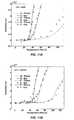
- FIG. 1which illustrates the large temporal variations of heat load on the external skin of a hypersonic vehicle for a typical mission, shows that the maximum convective heat transfer coefficient, “h” and the adiabatic wall temperature, T aw occur at different times in the trajectory of such a vehicle (note that the speed of such a vehicle after 95 seconds is approximately Mach 3).
- hthe maximum convective heat transfer coefficient
- T awthe adiabatic wall temperature
- Numerous other structureslikewise function more effectively if maintained within a desired temperature range (or within other specified parameter limits) but suffer from similar inefficiencies in maintaining the desired parameters.
- other examples of structureswhere it is desirable to maintain the structure within a specified temperature range includes gas turbine blades, nuclear reactors, combustors, heat exchangers, rocket engines and various components of aerospace vehicles including hypersonic vehicles.
- the number of components and structures that require some kind of parameter (e.g., thermal) management, and wherein the parameter is transient and asymmetricalis virtually limitless.
- a thermal management systemincludes a skin panel having a first surface, a second surface and at least one micropore extending from the first surface and the second surface.
- a flow pathextends between a source of coolant and the at least one micropore.
- At least one adaptive structureis associated with the at least one micropore and is configured to alter a flow rate of coolant through the at least one micropore responsive to temperature sensed by the at least one adaptive structure.
- an adaptive structurein accordance with another embodiment of the present invention, includes a first structure and at least one microstructure associated with the first structure.
- the at least one microstructureincludes a microscale beam configured to be displaced relative to the first structure upon the adaptive structure being exposed to a specified temperature.
- a method of cooling a structureincludes providing a source of coolant and flowing coolant from the source to a skin panel associated with the structure and through at least one micropore formed in the skin panel.
- An adaptive structureis associated with the at least one micropore and a temperature is sensed by the adaptive structure.
- a flow of coolant through the at least one microporeis altered by the adaptive structure responsive to the sensed temperature.
- FIG. 1is a graph related to heating issues and thermal management of an aerospace vehicle.
- FIG. 2Ashows an aerospace vehicle in accordance with an embodiment of the present invention
- FIG. 2Eshows a cross-sectional view of a microstructure utilized in conjunction with the structure set forth in FIGS. 2B-2D ;
- FIG. 2Gshows a plan view of yet another microstructure in accordance with a further embodiment of the present invention.
- FIGS. 5A and 5Billustrate equivalent loadings of pinned-pinned beams
- FIG. 8shows nondimensional stress components for a beam
- FIGS. 10A and 10Bare schematics of an experimental setup
- the actuatormay include a flap or a beam 120 formed of a desired material and exhibiting a desired shape such that, in reaction to an increase in temperature, and as indicated by a dashed line, the beam 120 deflects away from the opening 122 of its associated pore 116 (e.g., due to thermal expansion of the beam 120 or a portion thereof), enabling the flow rate of coolant 110 through the pore 116 to increase. Upon a decrease in temperature, the beam 120 may deflect back toward the opening 122 of the pore 116 , again changing the flow rate of coolant through the pore 116 .
- the beam 120may be configured to deflect, or be displaced, upon sensing of one or more threshold temperatures to provide a flow rate of coolant 110 that is adequate to transfer a desired amount of heat away from the structure (e.g., the engine wall 102 ) and maintain the structure within a specified temperature range. Moreover, not only may the beam 120 be configured to be actuated at a desired temperature (or within a desired temperature range), but the beam 120 may also be configured to be displaced in accordance with a desired relationship with the temperature variation of the structure (e.g., the engine wall 102 ). For example, the beam 120 may be configured to exhibit a linear or a nonlinear displacement relationship with the temperature variation of the associated structure depending on specific cooling needs.
- Such tailoring of the flap or the beam 120may be accomplished, for example, by tailoring the geometric configuration of the flap or the beam 120 , by tailoring the material from which the flap or the beam 120 is formed, through the manner in which the flap or the beam 120 is coupled to an underlying material, or a combination of such techniques.
- the self-regulating skin panel 114may be fabricated using microfabrication processes utilized in the semiconductor and microeletromechanical systems (MEMS) industries as will be appreciated by those of ordinary skill in the art.
- MEMSmicroeletromechanical systems
- Such processesmay include, for example, film deposition, lithographic patterning, and etching to create planar arrays of devices or adaptive structures having micron (or micrometer) scale features on or through, for example, a Si or SiC substrate.
- the skin panels 114may be mounted to coolant distribution webs, which may be integrally formed with the structure that is being cooled (e.g., the engine wall 102 ) such as, for example, through fusion bonding, brazing, or glass bead fusing.
- the adaptive structure 118 ′includes an actuator in the form of an elongated slender beam 120 ′ that, rather than being free at one end (or cantilevered at a single end thereof), is constrained at both ends, causing the beam to buckle in the middle upon actuation thereof.
- the actuator or beam 120 ′when in a nonactuated state, such as when the temperature of an associated structure is below a threshold temperature, the actuator or beam 120 ′ remains in an unactuated state (as shown in dashed lines) to prevent, or at least limit, the flow of coolant 110 through an associated pore (not shown in FIG. 2F ).
- the actuator or beam 120 ′When actuated, the actuator or beam 120 ′ buckles such that the central portion thereof deflects away from the skin panel 114 to increase the flow rate of coolant through the associated pore. It is additionally noted that, in the embodiment shown in FIG. 2F , the actuator or beam 120 ′ is not located on the surface of the skin panel 114 that is exposed to the heat source, but is located on an opposing side thereof.
- the adaptive structure 118 ′′includes a beam having a main body portion 130 sized and configured to cover, or at least substantially cover, the opening 122 of an associated pore 116 .
- One or more lateral displacement members 132are coupled with the main body portion 130 and attached to, or otherwise integrated with, the skin panel 114 .
- the displacement members 132may be appendages from the main body portion 130 and substantially integrally formed therewith, or they may be coupled to the main body portion 130 by some other means.
- the displacement members 132When the structure (e.g., engine wall 102 ( FIG. 2A )) to which the adaptive structure 118 ′′ is attached exhibits a temperature below a threshold level, the displacement members 132 remain in a first, nonactuated position (shown in dashed lines) such that the main body portion 130 covers, or at least partially covers, the opening 122 of the pore 116 to prevent or limit flow of coolant 110 therefrom. Upon reaching or exceeding a threshold temperature, the displacement members 132 deflect laterally relative to the pore 116 to expose a larger area of the opening 122 and increase the flow rate of the coolant 110 .
- a threshold temperatureUpon reaching or exceeding a threshold temperature, the displacement members 132 deflect laterally relative to the pore 116 to expose a larger area of the opening 122 and increase the flow rate of the coolant 110 .
- the adaptive structure 118 ′′deflects laterally (i.e., in a direction that is generally parallel with respect to a surface of skin panel 114 with which the adaptive structure 118 ′′ is associated). This is in contrast to the embodiment previously described wherein the beam 120 is displaced away from or toward the surface of the skin panel 114 .
- FIG. 2Han enlarged portion of air foil 104 is shown which incorporates an adaptive structure 140 in accordance with yet another embodiment of the present invention.
- a flow pathsuch as an air flow path within a portion of an engine
- a cooling techniqueincludes impingement cooling or wall cooling wherein coolant is sprayed against (or otherwise contacts) a backside or a surface of the structure that is relatively remote from the source of heat to which the structure is exposed.
- thermocouple 144 or other devicemay be embedded in or otherwise be associated with a portion of the air foil 104 to sense a change in temperature experienced by the air foil 104 at a particular location.
- thermocouple 144Due to the thermoelectric effect employed by the thermocouple 144 (generally the effect of converting a temperature differential to an electrical voltage and vice versa, as will be appreciated by those of ordinary skill in the art), an electrical voltage may be established via an electrical conductor 146 to actuate a beam 148 or other displaceable component of the adaptive structure 140 .
- the beam 148may be disposed within a coolant flow path 150 such that, prior to actuation (such as shown by dashed lines) the beam 148 or a portion thereof prevents, or at least limits, the flow of coolant 110 that is to impinge upon the back surface 152 of the air foil 104 or other structure.
- the beam 148Upon application of the voltage from the thermocouple 144 , the beam 148 is displaced (such as indicated by solid lines) such that the flow rate of coolant 110 is increased.
- the displaceable component or beam 148may be formed from a shape memory alloy (SMA).
- SMAshape memory alloy
- the displaceable component or beam 148may be formed of an SMA material including nickel and titanium.
- Nitinola material commercially known as Nitinol, which includes approximately 55% nickel by weight and approximately 45% titanium by weight.
- the SMAis a material that is deformed and then, when heated, returns to its original form or shape.
- the adaptive structure 140can be viewed as a combination of a sensor, an actuator, and a control subsystem. Using MEMS technology, these functions may be integrated on a chip to provide autonomous, local thermal management. As already mentioned, numerous approaches are possible to implement such a device or adaptive structure for sensing, actuation, and control.
- thermomechanical control approachmay be used (i.e., without electronics) such as has been described with particular reference to FIGS. 2E and 2F .
- a local increase in wall temperaturewill lead to a mechanical deformation (via thermal expansion), which in turn affects the coolant flow rate.
- analog or digital electronicsmay limit the control algorithms to the simplest strategies, such as proportional control.
- the thermomechanical implementationcan be extremely simple, reliable, completely autonomous, require no external wiring, and be suitable for use in high temperature environments.
- differential thermal expansionmay be used as a mechanical actuation and control mechanism.
- thermal expansiondue to temperature gradients, results in non-uniform expansion of the adaptive structure (or actuating component thereof).
- Such a mechanismmay be implemented using SiC and used in high temperature environments. Additionally, such an approach enables the adaptive structure to exhibit a substantially linear response. It is noted, however, the differential expansion conventionally results in rather small deflections and such a mechanism is rather sensitive to temperature distributions.
- Bimorph thermal expansionis similar to differential thermal expansion, but utilizes multiple materials having different thermal expansion coefficients so as to induce non-uniform deformation. Deflections of a larger magnitude, as compared to differential expansion, are possible using bimorph expansion and such a mechanism is less sensitive to temperature distribution. However, response of bimorph structures is moderately nonlinear and construction of a structure based on bimorph expansion is more involved because it inherently requires the use of two high temperature materials (e.g., two different metallic materials).
- Shape memory alloysare unique materials that undergo a material property phase transformation in their crystal structure that is temperature dependent. This phase transformation is responsible for the shape memory and superelastic properties of these alloys. These metallic materials possess the ability to return to some previously defined shape or size when subjected to certain temperature characteristics. SMAs can be plastically deformed at some relatively low temperature and can then be returned to their original shape once exposed to some higher temperature. When the SMA is heated above its transformation temperature, it can recover a preset shape and size; upon cooling, the SMA returns to an alternate shape.
- the transformation temperature for NiTiranges from 30° F. to 250° F. and can occur either by direct heat or by applying an electric current that generates heat (ohmic heating).
- Thin film NiTican also be superelastic and, in a certain state, behaves like rubber in that it is capable of attaining extreme angles and may be deformed into small shapes. In its opposite state, the NiTi material resorts to a different shape and is very rigid. NiTi is very flexible and possesses the largest energy density of any active material, generating a large force during the shape changing process.
- examplesinclude direct thermal sensing, conductive thermal sensing and thermoelectric approaches.
- Direct thermal sensingincludes exposing the adaptive structure, or at least the actuator component thereof, directly to the heat source (e.g., hot gases). Such an approach provides relative certainty in the results of the sensing.
- the heat sourcee.g., hot gases.
- direct sensingdepending on the environment in which the sensor is exposed, may require the use of high temperature materials in the adaptive structure.
- sensemeans the passive or active recognition by an element or feature or a combination of elements or features of an adaptive structure, of one or more stimuli in the form of variations in selected parameters such as, for example, temperature, such recognition being usable to initiate or vary a response by the adaptive structure.
- Thermoelectric sensingincludes sensing the temperature of a structure, for example, at or near a surface that is exposed to the heat source using a thermocouple or similar device to establish an electric potential.
- a thermocouple or similar deviceto establish an electric potential.
- Embodiments of the present inventionmay also be used for in applications other than thermal management systems.
- various types of flow controlsmay be managed by embodiments of the present invention.
- One exampleincludes control of impulse thrust of, for example, a missile or rocket, enabling directional thrust to be effected through a desired surface of the missile or rocket and providing the rocket or missile with a high degree of maneuverability.
- such adaptive microstructuresmay be utilized in sensing flow separation about an air foil and responding to such flow separation in a desired manner.
- ⁇ MP bh ⁇ [ 1 + 3 ⁇ ( e / h ) ⁇ sec ⁇ ( L 2 ⁇ P / EI ) ] . ( 7 )
- Equations (4) and (7)define the beam central deflection and maximum stress as a function of axial load. An additional relation is needed to relate the axial force, P, to the average beam temperature rise, ⁇ T.
- ⁇is the difference in the coefficient of thermal expansion between the beam and the substrate
- ⁇ Tis the average temperature rise of the beam
- ⁇ Ais the axial stress
- ⁇ ′is the strain due to beam elongation:
- ⁇ ′l - L L , ( 9 ) where l is defined as the deformed beam length, which is given by:
- ⁇ T cra Critical Temperature Rise
- FIGS. 6 , 7 and 9provide succinct nondimensional design curves for the implementation of thermally actuated buckled beams in MEMS systems. These curves, along with the preceding analysis, capture the complex and highly nonlinear behavior exhibited in thermally buckled beams.
- the beam shape, central deflection and state of stresshave all been modeled as they vary with temperature rise and eccentricity.
- Thickness, eccentricity and surface roughness measurementswere taken using a profilometer.
- the surface roughnesswas ⁇ 1 ⁇ m, while the variation in thickness across a single beam was measured to be ⁇ 2 ⁇ m for the beams tested in this work.
- the theoretical results shown hereare obtained by evaluating the nondimensional predictions for each beam's specific geometry and adjusting to account for the residual stress.
- the designed tensile residual stress in the beamswill lead to an actuation temperature offset. A small rise in temperature will be required to overcome the tensile stress imparted during microfabrication.
- the resultant temperature offsetswere used to determine the residual tensile stress in the nickel deposition for the two sets of beams fabricated. Beams A, B and C were offset by a temperature difference of approximately 27° C., while beams D, E and F were offset by a temperature difference of approximately 31° C.
- the corresponding residual tensile stressesare 5 MPa (megapascals) and 62 MPa, respectively, for the two sets. These stresses are in good agreement with the predicted values.
- a high purity bath of the composition and operating conditions used in this workhas been reported to produce depositions with residual tensile stresses of 55 MPa or less.
- FIGS. 12A and 12Bshow relatively good agreement between the theoretical predictions and the measured deflections.
- the 30 ⁇ m beams(A, B and C) show a larger amount of scatter in the data than that of the 60 ⁇ m beams (D, E and F). This is explained by the sensitivity of the optical probe measurements; the thinner beams have smaller deflections leading to higher percent errors.
- the beams tested in the current workwere scanned with a profilometer before and after thermal actuation to examine the onset and effect of plastic deformation.
- the central deflection of the beams after returning back to ambient conditionsis listed in Table 3 along with the calculated maximum stress experienced by each beam.
- a nickel electroplating bath of the composition and operating conditions used in this workhas been reported to produce depositions with yield strengths of 400 MPa to 600 MPa.
- Table 3shows the onset of an appreciable hysteresis effect occurring around 450 MPa for the beams tested in this work.
- FIGS. 13A and 13Bshow good repeatability of the test results for beams actuated with negligible plastic deformation.
Landscapes
- Engineering & Computer Science (AREA)
- Aviation & Aerospace Engineering (AREA)
- Physics & Mathematics (AREA)
- Fluid Mechanics (AREA)
- Mechanical Engineering (AREA)
- Thermal Sciences (AREA)
- Health & Medical Sciences (AREA)
- Critical Care (AREA)
- Emergency Medicine (AREA)
- General Health & Medical Sciences (AREA)
- Remote Sensing (AREA)
- Micromachines (AREA)
Abstract
Description
which has the following solution:
Maximum Stress
yields the maximum stress in the buckled beam:
where l is defined as the deformed beam length, which is given by:
and the strain term in Eq. (8) can, therefore, be rewritten as:
which defines the relationship between applied axial load and average temperature rise of the beam.
Nondimensional Design Curves
a Critical Temperature Rise, ΔTcr, can be defined by evaluating Eq. (8) at the critical load, noting that for a perfect beam prior to buckling, there is no deflection and, therefore, no associated strain term, ε′:
| TABLE 1 |
| Beam Geometries |
| Beam | Length (L) | Thickness (h) | Eccentricity (e) |
| A | 1000 | 30 μm | 1.5 | ||
| B | |||||
| 2000 | 30 μm | 1.5 | |||
| C | |||||
| 3000 | 30 μm | 1.5 | |||
| D | |||||
| 2000 | 60 μm | 0.75 | |||
| E | |||||
| 3000 | 60 μm | 0.75 | μm | ||
| F | 4000 | μm+ | 60 μm | 0.75 | μm |
| TABLE 2 |
| Process conditions for nickel electroplating |
| with a sulfur activated anode & mechanical agitation |
| Composition | Operating Conditions | ||
| 500 | g/L | Ni (SO3NH2)2 | pH value | 4-4.5 | ||
| 30 | g/L | H3BO3 | Temperature | 35° C. | ||
| 3 | g/L | Laurel Sulfate | Cur. Dens. | 10 mA/cm2 | ||
Experimental Setup
| TABLE 3 |
| Permanent deflection due to plastic deformation and the corresponding |
| calculated maximum stress for each beam geometry |
| Permanent Deflection | Calculated Maximum Stress | |
| Beam | (μm) | (MPa) |
| A | 1.25 | 400 |
| B | 1.00 | 150 |
| C | 0.50 | 75 |
| D | 10.25 | 450 |
| E | 4.00 | 250 |
| F | 2.00 | 150 |
Repeatability
Claims (9)
Priority Applications (1)
| Application Number | Priority Date | Filing Date | Title |
|---|---|---|---|
| US13/072,518US8534570B2 (en) | 2005-11-04 | 2011-03-25 | Adaptive structures, systems incorporating same and related methods |
Applications Claiming Priority (3)
| Application Number | Priority Date | Filing Date | Title |
|---|---|---|---|
| US73398005P | 2005-11-04 | 2005-11-04 | |
| US11/556,988US7913928B2 (en) | 2005-11-04 | 2006-11-06 | Adaptive structures, systems incorporating same and related methods |
| US13/072,518US8534570B2 (en) | 2005-11-04 | 2011-03-25 | Adaptive structures, systems incorporating same and related methods |
Related Parent Applications (1)
| Application Number | Title | Priority Date | Filing Date |
|---|---|---|---|
| US11/556,988ContinuationUS7913928B2 (en) | 2005-11-04 | 2006-11-06 | Adaptive structures, systems incorporating same and related methods |
Publications (2)
| Publication Number | Publication Date |
|---|---|
| US20110284645A1 US20110284645A1 (en) | 2011-11-24 |
| US8534570B2true US8534570B2 (en) | 2013-09-17 |
Family
ID=38089754
Family Applications (2)
| Application Number | Title | Priority Date | Filing Date |
|---|---|---|---|
| US11/556,988Active2029-11-30US7913928B2 (en) | 2005-11-04 | 2006-11-06 | Adaptive structures, systems incorporating same and related methods |
| US13/072,518Active2027-02-05US8534570B2 (en) | 2005-11-04 | 2011-03-25 | Adaptive structures, systems incorporating same and related methods |
Family Applications Before (1)
| Application Number | Title | Priority Date | Filing Date |
|---|---|---|---|
| US11/556,988Active2029-11-30US7913928B2 (en) | 2005-11-04 | 2006-11-06 | Adaptive structures, systems incorporating same and related methods |
Country Status (1)
| Country | Link |
|---|---|
| US (2) | US7913928B2 (en) |
Cited By (2)
| Publication number | Priority date | Publication date | Assignee | Title |
|---|---|---|---|---|
| US20150354907A1 (en)* | 2012-11-28 | 2015-12-10 | The Boeing Company | High heat transfer rate reusable thermal protection system |
| US10231360B2 (en) | 2016-11-09 | 2019-03-12 | Lockheed Martin Corporation | Dual-mode passive thermal management system and method |
Families Citing this family (11)
| Publication number | Priority date | Publication date | Assignee | Title |
|---|---|---|---|---|
| US8783337B2 (en)* | 2006-12-01 | 2014-07-22 | The Invention Science Fund I Llc | System for changing the convective heat transfer coefficient for a surface |
| US9002484B2 (en)* | 2006-12-01 | 2015-04-07 | The Invention Science Fund I Llc | System and method for deforming surfaces |
| EP3827174A1 (en) | 2018-07-24 | 2021-06-02 | Deep Science, LLC | Systems and methods for active control of surface drag |
| CN113039367B (en) | 2018-11-06 | 2023-08-04 | 深度科学有限责任公司 | System and method for actively controlling surface drag using wall coupling |
| CN113165733B (en) | 2018-11-30 | 2024-12-17 | 深度科学有限责任公司 | System and method for actively controlling surface drag using selective wave generation |
| CN110697023A (en)* | 2019-11-19 | 2020-01-17 | 中国飞机强度研究所 | Wing trailing edge bending degree structure |
| US11905983B2 (en) | 2020-01-23 | 2024-02-20 | Deep Science, Llc | Systems and methods for active control of surface drag using electrodes |
| US12065236B2 (en) | 2020-01-23 | 2024-08-20 | Enterprise Science Fund, Llc | Systems and methods for active control of surface drag using intermittent or variable actuation |
| WO2022177960A1 (en) | 2021-02-17 | 2022-08-25 | Deep Science, Llc | In-plane transverse momentum injection to disrupt large-scale eddies in a turbulent boundary layer |
| US20250084834A1 (en)* | 2023-09-08 | 2025-03-13 | Hamilton Sundstrand Corporation | Aircraft flow control device formed of thermally adaptive materials and a thermoelectric junction |
| US12384515B2 (en) | 2023-09-08 | 2025-08-12 | Hamilton Sundstrand Corporation | Airfoil formed of thermally adaptive materials and a thermoelectric junction |
Citations (82)
| Publication number | Priority date | Publication date | Assignee | Title |
|---|---|---|---|---|
| US3436017A (en) | 1967-05-04 | 1969-04-01 | Dynair Ltd | Temperature fluid control valves |
| US3690065A (en) | 1970-10-12 | 1972-09-12 | Louis Bucalo | Thermal actuator and method of making |
| US3808833A (en) | 1973-04-03 | 1974-05-07 | Us Navy | Compact transpiration cooling system |
| US3908936A (en) | 1974-10-22 | 1975-09-30 | Us Air Force | Multiple fluid flow proportioning system |
| US4581624A (en) | 1984-03-01 | 1986-04-08 | Allied Corporation | Microminiature semiconductor valve |
| JPS6189998A (en) | 1984-10-11 | 1986-05-08 | Mitsubishi Heavy Ind Ltd | Hydraulic machine |
| US4739952A (en) | 1986-08-04 | 1988-04-26 | The United States Of America As Represented By The Secretary Of The Army | Integral cooling system for high-temperature missile structures |
| US4821997A (en) | 1986-09-24 | 1989-04-18 | The Board Of Trustees Of The Leland Stanford Junior University | Integrated, microminiature electric-to-fluidic valve and pressure/flow regulator |
| US4824073A (en) | 1986-09-24 | 1989-04-25 | Stanford University | Integrated, microminiature electric to fluidic valve |
| US4943032A (en) | 1986-09-24 | 1990-07-24 | Stanford University | Integrated, microminiature electric to fluidic valve and pressure/flow regulator |
| US4966646A (en) | 1986-09-24 | 1990-10-30 | Board Of Trustees Of Leland Stanford University | Method of making an integrated, microminiature electric-to-fluidic valve |
| US5050838A (en) | 1990-07-31 | 1991-09-24 | Hewlett-Packard Company | Control valve utilizing mechanical beam buckling |
| US5054522A (en) | 1989-05-29 | 1991-10-08 | Burkert Gmbh Werk Ingelfingen | Microvalve |
| US5058856A (en) | 1991-05-08 | 1991-10-22 | Hewlett-Packard Company | Thermally-actuated microminiature valve |
| US5065978A (en) | 1988-04-27 | 1991-11-19 | Dragerwerk Aktiengesellschaft | Valve arrangement of microstructured components |
| US5074629A (en) | 1988-10-26 | 1991-12-24 | Stanford University | Integrated variable focal length lens and its applications |
| US5082242A (en) | 1989-12-27 | 1992-01-21 | Ulrich Bonne | Electronic microvalve apparatus and fabrication |
| US5209291A (en) | 1991-06-28 | 1993-05-11 | Hughes Aircraft Company | Cooling apparatus for optical devices |
| US5291830A (en) | 1992-10-30 | 1994-03-08 | Lockheed Corporation | Dual-mode semi-passive nosetip for a hypersonic weapon |
| US5333831A (en) | 1993-02-19 | 1994-08-02 | Hewlett-Packard Company | High performance micromachined valve orifice and seat |
| WO1995008716A2 (en) | 1993-09-24 | 1995-03-30 | Rosemount Analytical Inc. | Micromachined valve apparatus |
| GB2292608A (en) | 1994-08-24 | 1996-02-28 | Hewlett Packard Co | Microactuator |
| US5702618A (en) | 1993-10-04 | 1997-12-30 | Research International, Inc. | Methods for manufacturing a flow switch |
| WO1998004108A1 (en) | 1996-07-22 | 1998-01-29 | Northrop Grumman Corporation | Microchannel cooling using aviation fuels for airborne electronics |
| US5785295A (en) | 1996-08-27 | 1998-07-28 | Industrial Technology Research Institute | Thermally buckling control microvalve |
| US5825275A (en) | 1995-10-27 | 1998-10-20 | University Of Maryland | Composite shape memory micro actuator |
| US5899067A (en) | 1996-08-21 | 1999-05-04 | Hageman; Brian C. | Hydraulic engine powered by introduction and removal of heat from a working fluid |
| WO1999024744A1 (en) | 1997-11-12 | 1999-05-20 | California Institute Of Technology | Micromachined parylene membrane valve and pump |
| US5909078A (en) | 1996-12-16 | 1999-06-01 | Mcnc | Thermal arched beam microelectromechanical actuators |
| WO1999039120A1 (en) | 1998-01-29 | 1999-08-05 | University Of Pittsburgh | Thermal expansion-induced fluid control for microfluidic devices |
| US5954079A (en) | 1996-04-30 | 1999-09-21 | Hewlett-Packard Co. | Asymmetrical thermal actuation in a microactuator |
| US5955817A (en) | 1996-12-16 | 1999-09-21 | Mcnc | Thermal arched beam microelectromechanical switching array |
| US5969736A (en) | 1998-07-14 | 1999-10-19 | Hewlett-Packard Company | Passive pressure regulator for setting the pressure of a liquid to a predetermined pressure differential below a reference pressure |
| JP2000054122A (en) | 1998-08-03 | 2000-02-22 | Agency Of Ind Science & Technol | Production of titanium-nickel shape memory alloy thin film by substrate heating |
| US6039262A (en)* | 1998-09-14 | 2000-03-21 | The United States Of America As Represented By The Secretary Of The Army | Passive bimetallic actuator for heat transfer |
| US6070851A (en) | 1998-06-08 | 2000-06-06 | Industrial Technology Research Institute | Thermally buckling linear micro structure |
| EP1031735A2 (en) | 1999-02-23 | 2000-08-30 | Matsushita Electric Works, Ltd. | Microactuator |
| US6149123A (en) | 1996-09-27 | 2000-11-21 | Redwood Microsystems, Inc. | Integrated electrically operable micro-valve |
| US6168395B1 (en) | 1996-02-10 | 2001-01-02 | Fraunhofer-Gesellschaft Zur Foerderung Der Angewandten Forschung E.V. | Bistable microactuator with coupled membranes |
| WO2001001025A2 (en) | 1999-06-28 | 2001-01-04 | California Institute Of Technology | Microfabricated elastomeric valve and pump systems |
| US6345792B2 (en)* | 1998-03-31 | 2002-02-12 | Continuum Dynamics, Inc. | Actuating device with at least three stable positions |
| US6375901B1 (en) | 1998-06-29 | 2002-04-23 | Agilent Technologies, Inc. | Chemico-mechanical microvalve and devices comprising the same |
| US6386507B2 (en) | 1999-09-01 | 2002-05-14 | Jds Uniphase Corporation | Microelectromechanical valves including single crystalline material components |
| US6427948B1 (en)* | 2000-10-30 | 2002-08-06 | Michael Campbell | Controllable vortex generator |
| US20020177891A1 (en) | 2001-04-26 | 2002-11-28 | Parodi Juan Carlos | Endoluminal device and method for fabricating same |
| US6494433B2 (en) | 2000-06-06 | 2002-12-17 | The Regents Of The University Of Michigan | Thermally activated polymer device |
| US20030002994A1 (en) | 2001-03-07 | 2003-01-02 | Johnson A. David | Thin film shape memory alloy actuated flow controller |
| US6527003B1 (en) | 2000-11-22 | 2003-03-04 | Industrial Technology Research | Micro valve actuator |
| US20030098899A1 (en) | 2001-11-29 | 2003-05-29 | Samsung Electronics Co., Ltd. | Ink-jet printhead and manufacturing method thereof |
| US6590267B1 (en) | 2000-09-14 | 2003-07-08 | Mcnc | Microelectromechanical flexible membrane electrostatic valve device and related fabrication methods |
| US6613560B1 (en) | 1994-10-19 | 2003-09-02 | Agilent Technologies, Inc. | PCR microreactor for amplifying DNA using microquantities of sample fluid |
| US20030175947A1 (en) | 2001-11-05 | 2003-09-18 | Liu Robin Hui | Enhanced mixing in microfluidic devices |
| US6626417B2 (en) | 2001-02-23 | 2003-09-30 | Becton, Dickinson And Company | Microfluidic valve and microactuator for a microvalve |
| US6629820B2 (en) | 2001-06-26 | 2003-10-07 | Micralyne Inc. | Microfluidic flow control device |
| EP0708331B1 (en) | 1994-10-19 | 2004-03-24 | Agilent Technologies, Inc. (a Delaware corporation) | Fully integrated miniaturized planar liquid sample handling and analysis device |
| US20040076531A1 (en) | 2001-11-19 | 2004-04-22 | Ngk Insulators, Ltd. | Circuit changeover switch |
| US20040086427A1 (en) | 2002-10-31 | 2004-05-06 | Childers Winthrop D. | Microfluidic system utilizing thin-film layers to route fluid |
| US6761420B2 (en) | 1998-09-03 | 2004-07-13 | Ge Novasensor | Proportional micromechanical device |
| US6764166B2 (en) | 1997-07-15 | 2004-07-20 | Silverbrook Research Pty Ltd. | Ejecting ink using shape memory alloys |
| WO2004092581A1 (en) | 2003-04-15 | 2004-10-28 | Board Of Trustees Operating Michigan State University | Prestrained thin-film shape memory actuator using polymeric substrates |
| WO2004109163A2 (en) | 2003-06-06 | 2004-12-16 | Wouter Van Der Wijngaart | A micromachined knife gate valve for high-flow pressure regulation applications |
| US6877528B2 (en) | 2002-04-17 | 2005-04-12 | Cytonome, Inc. | Microfluidic system including a bubble valve for regulating fluid flow through a microchannel |
| US6883337B2 (en) | 2000-06-02 | 2005-04-26 | University Of Florida Research Foundation, Inc. | Thermal management device |
| US20050095143A1 (en) | 2003-11-04 | 2005-05-05 | Alcatel | Pumping apparatus using thermal transpiration micropumps |
| US20050116798A1 (en) | 2002-11-01 | 2005-06-02 | Bintoro Jemmy S. | Single substrate electromagnetic actuator |
| EP1544524A1 (en) | 2003-12-18 | 2005-06-22 | Ford Global Technologies, LLC, A subsidary of Ford Motor Company | Valve with a closing member comprising shape memory material and use of such a valve |
| US20050153273A1 (en) | 2001-08-06 | 2005-07-14 | Vanderbilt University | Device and methods for monitoring the status of at least one cell |
| US6953240B2 (en) | 2002-05-15 | 2005-10-11 | Eastman Kodak Company | Snap-through thermal actuator |
| WO2005107938A2 (en) | 2004-05-02 | 2005-11-17 | Fluidigm Corporation | Thermal reaction device and method for using the same |
| WO2005112156A2 (en) | 2004-05-14 | 2005-11-24 | Cambridge Consultants Limited | Apparatus for cooling a device comprising a fuel cell |
| US6988706B2 (en) | 2003-12-17 | 2006-01-24 | General Electric Company | Piezoelectric microvalve |
| US7011288B1 (en) | 2001-12-05 | 2006-03-14 | Microstar Technologies Llc | Microelectromechanical device with perpendicular motion |
| US7055781B2 (en) | 2003-06-05 | 2006-06-06 | The Boeing Company | Cooled insulation surface temperature control system |
| US7086604B2 (en) | 2002-07-12 | 2006-08-08 | Rolls-Royce Plc | Gate arrangement |
| US7118910B2 (en) | 2001-11-30 | 2006-10-10 | Fluidigm Corporation | Microfluidic device and methods of using same |
| US7125103B2 (en) | 1997-07-15 | 2006-10-24 | Silverbrook Research Pty Ltd | Fluid ejection device with a through-chip micro-electromechanical actuator |
| US7143762B2 (en) | 2003-02-07 | 2006-12-05 | Queen's University At Kingston | Method and apparatus for solar collector with integral stagnation temperature control |
| US7152960B2 (en) | 1997-07-15 | 2006-12-26 | Silverbrook Research Pty Ltd | Micro-electromechanical valve having transformable valve actuator |
| US7177505B2 (en) | 2004-03-04 | 2007-02-13 | Rosemount Inc. | MEMS-based actuator devices using electrets |
| US7188931B2 (en) | 2004-11-22 | 2007-03-13 | Eastman Kodak Company | Doubly-anchored thermal actuator having varying flexural rigidity |
| WO2007056267A2 (en) | 2005-11-04 | 2007-05-18 | The Trustees Of Columbia University In The City Of New York | Thermally actuated valves, photovoltaic cells and arrays comprising same, and methods for producing same |
| US7243705B2 (en) | 2005-03-01 | 2007-07-17 | Intel Corporation | Integrated circuit coolant microchannel with compliant cover |
- 2006
- 2006-11-06USUS11/556,988patent/US7913928B2/enactiveActive
- 2011
- 2011-03-25USUS13/072,518patent/US8534570B2/enactiveActive
Patent Citations (88)
| Publication number | Priority date | Publication date | Assignee | Title |
|---|---|---|---|---|
| US3436017A (en) | 1967-05-04 | 1969-04-01 | Dynair Ltd | Temperature fluid control valves |
| US3690065A (en) | 1970-10-12 | 1972-09-12 | Louis Bucalo | Thermal actuator and method of making |
| US3808833A (en) | 1973-04-03 | 1974-05-07 | Us Navy | Compact transpiration cooling system |
| US3908936A (en) | 1974-10-22 | 1975-09-30 | Us Air Force | Multiple fluid flow proportioning system |
| US4581624A (en) | 1984-03-01 | 1986-04-08 | Allied Corporation | Microminiature semiconductor valve |
| JPS6189998A (en) | 1984-10-11 | 1986-05-08 | Mitsubishi Heavy Ind Ltd | Hydraulic machine |
| US4739952A (en) | 1986-08-04 | 1988-04-26 | The United States Of America As Represented By The Secretary Of The Army | Integral cooling system for high-temperature missile structures |
| US4966646A (en) | 1986-09-24 | 1990-10-30 | Board Of Trustees Of Leland Stanford University | Method of making an integrated, microminiature electric-to-fluidic valve |
| US4824073A (en) | 1986-09-24 | 1989-04-25 | Stanford University | Integrated, microminiature electric to fluidic valve |
| US4943032A (en) | 1986-09-24 | 1990-07-24 | Stanford University | Integrated, microminiature electric to fluidic valve and pressure/flow regulator |
| US4821997A (en) | 1986-09-24 | 1989-04-18 | The Board Of Trustees Of The Leland Stanford Junior University | Integrated, microminiature electric-to-fluidic valve and pressure/flow regulator |
| EP0261972B1 (en) | 1986-09-24 | 1992-12-23 | The Board Of Trustees Of The Leland Stanford Junior University | Integrated, microminiature electric-to-fluidic valve and pressure/flow regulator and method of making same |
| US5065978A (en) | 1988-04-27 | 1991-11-19 | Dragerwerk Aktiengesellschaft | Valve arrangement of microstructured components |
| US5074629A (en) | 1988-10-26 | 1991-12-24 | Stanford University | Integrated variable focal length lens and its applications |
| US5054522A (en) | 1989-05-29 | 1991-10-08 | Burkert Gmbh Werk Ingelfingen | Microvalve |
| US5082242A (en) | 1989-12-27 | 1992-01-21 | Ulrich Bonne | Electronic microvalve apparatus and fabrication |
| US5050838A (en) | 1990-07-31 | 1991-09-24 | Hewlett-Packard Company | Control valve utilizing mechanical beam buckling |
| US5058856A (en) | 1991-05-08 | 1991-10-22 | Hewlett-Packard Company | Thermally-actuated microminiature valve |
| US5209291A (en) | 1991-06-28 | 1993-05-11 | Hughes Aircraft Company | Cooling apparatus for optical devices |
| US5291830A (en) | 1992-10-30 | 1994-03-08 | Lockheed Corporation | Dual-mode semi-passive nosetip for a hypersonic weapon |
| US5333831A (en) | 1993-02-19 | 1994-08-02 | Hewlett-Packard Company | High performance micromachined valve orifice and seat |
| WO1995008716A2 (en) | 1993-09-24 | 1995-03-30 | Rosemount Analytical Inc. | Micromachined valve apparatus |
| US5702618A (en) | 1993-10-04 | 1997-12-30 | Research International, Inc. | Methods for manufacturing a flow switch |
| GB2292608A (en) | 1994-08-24 | 1996-02-28 | Hewlett Packard Co | Microactuator |
| US5529279A (en) | 1994-08-24 | 1996-06-25 | Hewlett-Packard Company | Thermal isolation structures for microactuators |
| US6613560B1 (en) | 1994-10-19 | 2003-09-02 | Agilent Technologies, Inc. | PCR microreactor for amplifying DNA using microquantities of sample fluid |
| EP0708331B1 (en) | 1994-10-19 | 2004-03-24 | Agilent Technologies, Inc. (a Delaware corporation) | Fully integrated miniaturized planar liquid sample handling and analysis device |
| US5825275A (en) | 1995-10-27 | 1998-10-20 | University Of Maryland | Composite shape memory micro actuator |
| US6168395B1 (en) | 1996-02-10 | 2001-01-02 | Fraunhofer-Gesellschaft Zur Foerderung Der Angewandten Forschung E.V. | Bistable microactuator with coupled membranes |
| US5954079A (en) | 1996-04-30 | 1999-09-21 | Hewlett-Packard Co. | Asymmetrical thermal actuation in a microactuator |
| WO1998004108A1 (en) | 1996-07-22 | 1998-01-29 | Northrop Grumman Corporation | Microchannel cooling using aviation fuels for airborne electronics |
| US5899067A (en) | 1996-08-21 | 1999-05-04 | Hageman; Brian C. | Hydraulic engine powered by introduction and removal of heat from a working fluid |
| US5785295A (en) | 1996-08-27 | 1998-07-28 | Industrial Technology Research Institute | Thermally buckling control microvalve |
| US6149123A (en) | 1996-09-27 | 2000-11-21 | Redwood Microsystems, Inc. | Integrated electrically operable micro-valve |
| US5909078A (en) | 1996-12-16 | 1999-06-01 | Mcnc | Thermal arched beam microelectromechanical actuators |
| US5955817A (en) | 1996-12-16 | 1999-09-21 | Mcnc | Thermal arched beam microelectromechanical switching array |
| US6114794A (en) | 1996-12-16 | 2000-09-05 | Cronos Integrated Microsystems, Inc. | Thermal arched beam microelectromechanical valve |
| US7152960B2 (en) | 1997-07-15 | 2006-12-26 | Silverbrook Research Pty Ltd | Micro-electromechanical valve having transformable valve actuator |
| US6764166B2 (en) | 1997-07-15 | 2004-07-20 | Silverbrook Research Pty Ltd. | Ejecting ink using shape memory alloys |
| US7066575B2 (en) | 1997-07-15 | 2006-06-27 | Silverbrook Research Pty Ltd | Micro-electromechanical fluid ejection device having a buckle-resistant actuator |
| US7125103B2 (en) | 1997-07-15 | 2006-10-24 | Silverbrook Research Pty Ltd | Fluid ejection device with a through-chip micro-electromechanical actuator |
| WO1999024744A1 (en) | 1997-11-12 | 1999-05-20 | California Institute Of Technology | Micromachined parylene membrane valve and pump |
| WO1999039120A1 (en) | 1998-01-29 | 1999-08-05 | University Of Pittsburgh | Thermal expansion-induced fluid control for microfluidic devices |
| US6345792B2 (en)* | 1998-03-31 | 2002-02-12 | Continuum Dynamics, Inc. | Actuating device with at least three stable positions |
| US6070851A (en) | 1998-06-08 | 2000-06-06 | Industrial Technology Research Institute | Thermally buckling linear micro structure |
| US6375901B1 (en) | 1998-06-29 | 2002-04-23 | Agilent Technologies, Inc. | Chemico-mechanical microvalve and devices comprising the same |
| US5969736A (en) | 1998-07-14 | 1999-10-19 | Hewlett-Packard Company | Passive pressure regulator for setting the pressure of a liquid to a predetermined pressure differential below a reference pressure |
| JP2000054122A (en) | 1998-08-03 | 2000-02-22 | Agency Of Ind Science & Technol | Production of titanium-nickel shape memory alloy thin film by substrate heating |
| US6761420B2 (en) | 1998-09-03 | 2004-07-13 | Ge Novasensor | Proportional micromechanical device |
| US6039262A (en)* | 1998-09-14 | 2000-03-21 | The United States Of America As Represented By The Secretary Of The Army | Passive bimetallic actuator for heat transfer |
| EP1031735A2 (en) | 1999-02-23 | 2000-08-30 | Matsushita Electric Works, Ltd. | Microactuator |
| WO2001001025A2 (en) | 1999-06-28 | 2001-01-04 | California Institute Of Technology | Microfabricated elastomeric valve and pump systems |
| US6386507B2 (en) | 1999-09-01 | 2002-05-14 | Jds Uniphase Corporation | Microelectromechanical valves including single crystalline material components |
| US6883337B2 (en) | 2000-06-02 | 2005-04-26 | University Of Florida Research Foundation, Inc. | Thermal management device |
| US6494433B2 (en) | 2000-06-06 | 2002-12-17 | The Regents Of The University Of Michigan | Thermally activated polymer device |
| US6590267B1 (en) | 2000-09-14 | 2003-07-08 | Mcnc | Microelectromechanical flexible membrane electrostatic valve device and related fabrication methods |
| US6427948B1 (en)* | 2000-10-30 | 2002-08-06 | Michael Campbell | Controllable vortex generator |
| US6527003B1 (en) | 2000-11-22 | 2003-03-04 | Industrial Technology Research | Micro valve actuator |
| US6626417B2 (en) | 2001-02-23 | 2003-09-30 | Becton, Dickinson And Company | Microfluidic valve and microactuator for a microvalve |
| US20030002994A1 (en) | 2001-03-07 | 2003-01-02 | Johnson A. David | Thin film shape memory alloy actuated flow controller |
| US20020177891A1 (en) | 2001-04-26 | 2002-11-28 | Parodi Juan Carlos | Endoluminal device and method for fabricating same |
| US6629820B2 (en) | 2001-06-26 | 2003-10-07 | Micralyne Inc. | Microfluidic flow control device |
| US20050153273A1 (en) | 2001-08-06 | 2005-07-14 | Vanderbilt University | Device and methods for monitoring the status of at least one cell |
| US20030175947A1 (en) | 2001-11-05 | 2003-09-18 | Liu Robin Hui | Enhanced mixing in microfluidic devices |
| US20040076531A1 (en) | 2001-11-19 | 2004-04-22 | Ngk Insulators, Ltd. | Circuit changeover switch |
| US20030098899A1 (en) | 2001-11-29 | 2003-05-29 | Samsung Electronics Co., Ltd. | Ink-jet printhead and manufacturing method thereof |
| US7118910B2 (en) | 2001-11-30 | 2006-10-10 | Fluidigm Corporation | Microfluidic device and methods of using same |
| US7011288B1 (en) | 2001-12-05 | 2006-03-14 | Microstar Technologies Llc | Microelectromechanical device with perpendicular motion |
| US6877528B2 (en) | 2002-04-17 | 2005-04-12 | Cytonome, Inc. | Microfluidic system including a bubble valve for regulating fluid flow through a microchannel |
| US6953240B2 (en) | 2002-05-15 | 2005-10-11 | Eastman Kodak Company | Snap-through thermal actuator |
| US7086604B2 (en) | 2002-07-12 | 2006-08-08 | Rolls-Royce Plc | Gate arrangement |
| US20040086427A1 (en) | 2002-10-31 | 2004-05-06 | Childers Winthrop D. | Microfluidic system utilizing thin-film layers to route fluid |
| US20050116798A1 (en) | 2002-11-01 | 2005-06-02 | Bintoro Jemmy S. | Single substrate electromagnetic actuator |
| US7143762B2 (en) | 2003-02-07 | 2006-12-05 | Queen's University At Kingston | Method and apparatus for solar collector with integral stagnation temperature control |
| WO2004092581A1 (en) | 2003-04-15 | 2004-10-28 | Board Of Trustees Operating Michigan State University | Prestrained thin-film shape memory actuator using polymeric substrates |
| US7055781B2 (en) | 2003-06-05 | 2006-06-06 | The Boeing Company | Cooled insulation surface temperature control system |
| WO2004109163A2 (en) | 2003-06-06 | 2004-12-16 | Wouter Van Der Wijngaart | A micromachined knife gate valve for high-flow pressure regulation applications |
| US20050095143A1 (en) | 2003-11-04 | 2005-05-05 | Alcatel | Pumping apparatus using thermal transpiration micropumps |
| US6988706B2 (en) | 2003-12-17 | 2006-01-24 | General Electric Company | Piezoelectric microvalve |
| EP1544524A1 (en) | 2003-12-18 | 2005-06-22 | Ford Global Technologies, LLC, A subsidary of Ford Motor Company | Valve with a closing member comprising shape memory material and use of such a valve |
| US7177505B2 (en) | 2004-03-04 | 2007-02-13 | Rosemount Inc. | MEMS-based actuator devices using electrets |
| WO2005107938A2 (en) | 2004-05-02 | 2005-11-17 | Fluidigm Corporation | Thermal reaction device and method for using the same |
| WO2005112156A2 (en) | 2004-05-14 | 2005-11-24 | Cambridge Consultants Limited | Apparatus for cooling a device comprising a fuel cell |
| US7188931B2 (en) | 2004-11-22 | 2007-03-13 | Eastman Kodak Company | Doubly-anchored thermal actuator having varying flexural rigidity |
| US7243705B2 (en) | 2005-03-01 | 2007-07-17 | Intel Corporation | Integrated circuit coolant microchannel with compliant cover |
| WO2007056267A2 (en) | 2005-11-04 | 2007-05-18 | The Trustees Of Columbia University In The City Of New York | Thermally actuated valves, photovoltaic cells and arrays comprising same, and methods for producing same |
| WO2007056267A3 (en) | 2005-11-04 | 2007-08-23 | Univ Columbia | Thermally actuated valves, photovoltaic cells and arrays comprising same, and methods for producing same |
| US20090095927A1 (en) | 2005-11-04 | 2009-04-16 | Mccarthy Matthew | Thermally actuated valves, photovoltaic cells and arrays comprising same, and methods for producing same |
Non-Patent Citations (21)
| Title |
|---|
| Angell, James B., et al., "Silicon Micromechanical Devices," Scientific American, Apr. 1983, pp. 44-55. |
| Becker, Mike, et al., "Electrostatic beam actuator for switching applications fabricated by Ni-microelectroplating and thermal postprocessing," Proc. of SPIE, vol. 4981, 2003, pp. 71-82. |
| Gabriel, K.J., et al., "A Micro Rotary Actuator Using Shape Memory Alloys," Sensors and Actuators, vol. 15, 1988, pp. 95-102. |
| Goll, C., et al., "An electrostatically actuated polymer microvalve equipped with a movable membrane electrode," J. Micromech. Microeng., vol. 7, 1997, pp. 224-226. |
| Jerman, Hal, "Electrically-Activated, Micromachined Diaphragm Valves," IEEE Solid-State Sensor and Actuator Workshop, 1990, pp. 65-69. |
| Jeung, Won-Kyu, et al., "Large Displacement Out-Of-Plane Bimorph Actuator for Optical Application," Key Engineering Materials, vols. 326-328, 2006, pp. 1383-1386. |
| Kohl, M., et al., "Development of Microactuators Based on the Shape Memory Effect," Internat'l. Conference on Martensitic Transformations, Journal de Physique IV, Colloque C8, Supplement of Journal de Physique III, No. 12, vol. 5, Dec. 1995, pp. C8-1187 through C8-1192. |
| Kohl, M., et al., "Development of stress-optimised shape memory microvalves," Sensors and Actuators, vol. 72, 1999, pp. 243-250. |
| Kohl, M., et al., "SMA microactuators for microvalve applications," J. Phys. IV France, vol. 115, 2004, pp. 333-342. |
| Kohl, Manfred, et al., "Shape memory micromechanisms for microvalve applications," Smart Structures and Materials 2004: Active Materials: Behavior and Mechanics, Proceedings of SPIE, vol. 5387, Mar. 15-18, 2004, pp. 106-117. |
| Krulevitch, P., et al., "Thin Film Shape Memory Alloy Microactuators," 1996 ASME Internat'l Mechanical Engineering Congress and Exposition, Micro-Electro-Mechanical Systems (MEMS), DSC-vol. 59, 1996, pp. 301-306. |
| Lisec, T., et al., "Thermally Driven Microvalve with Buckling Behaviour for Pneumatic Applications," IEEE, 0/7803-1833-1/94, 1994, pp. 13-17. |
| McCarthy et al., U.S. Appl. No. 60/802,380, filed May 22, 2006. |
| McCarthy et al., U.S. Appl. No. 60/817,673, filed Jun. 30, 2006. |
| McCarthy et al., U.S. Appl. No. 60/830,500, filed Jul. 13, 2006. |
| McCarthy, Matthew, et al., "Characterization and Modeling of Thermal Buckling in Eccentrically Loaded Microfabricated Nickel Beams for Adaptive Cooling," 2005 ASME Internat'l. Mechanical Engineering Congress and Exposition, Micro-Electro-Mechanical Systems, MEMS-vol. 7, Nov. 5-11, 2005, pp. 689-698. |
| Shoji, Shuchi, et al., "Microflow devices and systems," J. Micromech. Microeng., vol. 4, 1994, pp. 157-171. |
| Tabib-Azar, M., et al., "Applications of TiNi thin film shape memory alloys in micro-opto-electro-mechanical systems," Sensors and Actuators, vol. 77, 1999, pp. 34-38. |
| Takagi, Toshiyuki, et al., "A Study of an Electromagnetic Induced Heating Type SMA Valve," The Japan Society of Mechanical Engineering, 74th Edition, Lecture Presentation, Research Paper (I), 1997, 2 pages. |
| Takagi, Toshiyuki, et al., "Electromagneto Thermo-Structural Analysis of an ARSME Plate," Japanese Mechanical Society Papers Collection, 1998, pp. 182-189. |
| Tani, J., et al., "Application of shape memory alloy with all-round effect to flow control values," 4th European Conference on Smart Structures and Materials in Conjunction with the 2nd Internat'l. Conference on Micromechanics, Intelligent Materials and Robotics, Harrogate, UK, Jul. 6-8, 1998, pp. 337-340. |
Cited By (3)
| Publication number | Priority date | Publication date | Assignee | Title |
|---|---|---|---|---|
| US20150354907A1 (en)* | 2012-11-28 | 2015-12-10 | The Boeing Company | High heat transfer rate reusable thermal protection system |
| US9493228B2 (en)* | 2012-11-28 | 2016-11-15 | The Boeing Company | High heat transfer rate reusable thermal protection system |
| US10231360B2 (en) | 2016-11-09 | 2019-03-12 | Lockheed Martin Corporation | Dual-mode passive thermal management system and method |
Also Published As
| Publication number | Publication date |
|---|---|
| US7913928B2 (en) | 2011-03-29 |
| US20070113932A1 (en) | 2007-05-24 |
| US20110284645A1 (en) | 2011-11-24 |
Similar Documents
| Publication | Publication Date | Title |
|---|---|---|
| US8534570B2 (en) | Adaptive structures, systems incorporating same and related methods | |
| US20170066519A1 (en) | Thermally graded adaptive multifunctional cellular structures with shape memory alloys | |
| Takahashi et al. | Marangoni effect in microbubble systems | |
| Mueller et al. | Design, analysis and fabrication of a vaporizing liquid micro-thruster | |
| Scheller et al. | A combined smart-materials approach for next-generation airfoils | |
| Varadarajan et al. | Adaptive shape control of laminated composite plates using piezoelectric materials | |
| Hill et al. | Actuator grouping optimization on flexible space reflectors | |
| Jiao et al. | Extremely sharp bending and recoverability of nanoscale plates with honeycomb corrugation | |
| McCarthy et al. | Thermal buckling of eccentric microfabricated nickel beams as temperature regulated nonlinear actuators for flow control | |
| Tsao et al. | An integrated MEMS system for turbulent boundary layer control | |
| Calkins et al. | Subsonic jet noise reduction variable geometry chevron | |
| US20090095927A1 (en) | Thermally actuated valves, photovoltaic cells and arrays comprising same, and methods for producing same | |
| DeCastro et al. | System-level design of a shape memory alloy actuator for active clearance control in the high-pressure turbine | |
| Oh et al. | Active shape control of a double-plate structures using piezoceramicsand SMA wires | |
| Kim et al. | Development of two types of in-plane motion actuators with modular design and application to morphing wings | |
| Eckstein et al. | Thermally driven morphing with hybrid laminates and metal matrix composites | |
| Srinivasan et al. | Effect of heat transfer on materials selection for bimaterial electrothermal actuators | |
| Mabe et al. | Variable area jet nozzle using shape memory alloy actuators in an antagonistic design | |
| Necib et al. | The smart materials and their applications in the engineering fields | |
| Sassen et al. | An improved in-plane thermal folded V-beam actuator for optical fibre alignment | |
| Enikov et al. | Analytical and experimental analysis of folded beam and V-shaped thermal microactuators | |
| Ding et al. | Thermo-structural analysis of space structures using Fourier tube elements | |
| US8299411B2 (en) | Control surface actuation system | |
| McCarthy et al. | Characterization and modeling of thermal buckling in eccentrically loaded microfabricated nickel beams for adaptive cooling | |
| Beasley et al. | Design and packaging for a microelectromechanical thermal switch radiator |
Legal Events
| Date | Code | Title | Description |
|---|---|---|---|
| AS | Assignment | Owner name:BANK OF AMERICA, N.A., CALIFORNIA Free format text:INTELLECTUAL PROPERTY SECURITY AGREEMENT SUPPLEMENT;ASSIGNOR:ALLIANT TECHSYSTEMS, INC.;REEL/FRAME:026196/0900 Effective date:20110331 | |
| FEPP | Fee payment procedure | Free format text:PAYOR NUMBER ASSIGNED (ORIGINAL EVENT CODE: ASPN); ENTITY STATUS OF PATENT OWNER: LARGE ENTITY | |
| STCF | Information on status: patent grant | Free format text:PATENTED CASE | |
| AS | Assignment | Owner name:BANK OF AMERICA, N.A., CALIFORNIA Free format text:SECURITY AGREEMENT;ASSIGNORS:ALLIANT TECHSYSTEMS INC.;CALIBER COMPANY;EAGLE INDUSTRIES UNLIMITED, INC.;AND OTHERS;REEL/FRAME:031731/0281 Effective date:20131101 | |
| CC | Certificate of correction | ||
| AS | Assignment | Owner name:WELLS FARGO BANK, NATIONAL ASSOCIATION, AS ADMINISTRATIVE AGENT, NORTH CAROLINA Free format text:SECURITY AGREEMENT;ASSIGNORS:ORBITAL ATK, INC.;ORBITAL SCIENCES CORPORATION;REEL/FRAME:036732/0170 Effective date:20150929 Owner name:WELLS FARGO BANK, NATIONAL ASSOCIATION, AS ADMINIS Free format text:SECURITY AGREEMENT;ASSIGNORS:ORBITAL ATK, INC.;ORBITAL SCIENCES CORPORATION;REEL/FRAME:036732/0170 Effective date:20150929 | |
| AS | Assignment | Owner name:ORBITAL ATK, INC. (F/K/A ALLIANT TECHSYSTEMS INC.), VIRGINIA Free format text:RELEASE BY SECURED PARTY;ASSIGNOR:BANK OF AMERICA, N.A.;REEL/FRAME:036816/0624 Effective date:20150929 Owner name:EAGLE INDUSTRIES UNLIMITED, INC., MISSOURI Free format text:RELEASE BY SECURED PARTY;ASSIGNOR:BANK OF AMERICA, N.A.;REEL/FRAME:036816/0624 Effective date:20150929 Owner name:FEDERAL CARTRIDGE CO., MINNESOTA Free format text:RELEASE BY SECURED PARTY;ASSIGNOR:BANK OF AMERICA, N.A.;REEL/FRAME:036816/0624 Effective date:20150929 Owner name:AMMUNITION ACCESSORIES, INC., ALABAMA Free format text:RELEASE BY SECURED PARTY;ASSIGNOR:BANK OF AMERICA, N.A.;REEL/FRAME:036816/0624 Effective date:20150929 Owner name:ALLIANT TECHSYSTEMS INC., VIRGINIA Free format text:RELEASE BY SECURED PARTY;ASSIGNOR:BANK OF AMERICA, N.A.;REEL/FRAME:036816/0624 Effective date:20150929 Owner name:ORBITAL ATK, INC. (F/K/A ALLIANT TECHSYSTEMS INC.) Free format text:RELEASE BY SECURED PARTY;ASSIGNOR:BANK OF AMERICA, N.A.;REEL/FRAME:036816/0624 Effective date:20150929 | |
| FPAY | Fee payment | Year of fee payment:4 | |
| AS | Assignment | Owner name:ORBITAL ATK, INC., MINNESOTA Free format text:CHANGE OF NAME;ASSIGNOR:ALLIANT TECHSYSTEMS INC.;REEL/FRAME:044824/0466 Effective date:20150209 | |
| AS | Assignment | Owner name:ORBITAL ATK, INC., VIRGINIA Free format text:TERMINATION AND RELEASE OF SECURITY INTEREST IN PATENTS;ASSIGNOR:WELLS FARGO BANK, NATIONAL ASSOCIATION, AS ADMINISTRATIVE AGENT;REEL/FRAME:046477/0874 Effective date:20180606 | |
| AS | Assignment | Owner name:NORTHROP GRUMMAN INNOVATION SYSTEMS, INC., MINNESOTA Free format text:CHANGE OF NAME;ASSIGNOR:ORBITAL ATK, INC.;REEL/FRAME:047400/0381 Effective date:20180606 Owner name:NORTHROP GRUMMAN INNOVATION SYSTEMS, INC., MINNESO Free format text:CHANGE OF NAME;ASSIGNOR:ORBITAL ATK, INC.;REEL/FRAME:047400/0381 Effective date:20180606 | |
| AS | Assignment | Owner name:NORTHROP GRUMMAN INNOVATION SYSTEMS LLC, MINNESOTA Free format text:CHANGE OF NAME;ASSIGNOR:NORTHROP GRUMMAN INNOVATION SYSTEMS, INC.;REEL/FRAME:055223/0425 Effective date:20200731 | |
| AS | Assignment | Owner name:NORTHROP GRUMMAN SYSTEMS CORPORATION, MINNESOTA Free format text:ASSIGNMENT OF ASSIGNORS INTEREST;ASSIGNOR:NORTHROP GRUMMAN INNOVATION SYSTEMS LLC;REEL/FRAME:055256/0892 Effective date:20210111 | |
| MAFP | Maintenance fee payment | Free format text:PAYMENT OF MAINTENANCE FEE, 8TH YEAR, LARGE ENTITY (ORIGINAL EVENT CODE: M1552); ENTITY STATUS OF PATENT OWNER: LARGE ENTITY Year of fee payment:8 | |
| MAFP | Maintenance fee payment | Free format text:PAYMENT OF MAINTENANCE FEE, 12TH YEAR, LARGE ENTITY (ORIGINAL EVENT CODE: M1553); ENTITY STATUS OF PATENT OWNER: LARGE ENTITY Year of fee payment:12 |