US8534425B2 - Method for regulating the level of a section of an oil tray comprising at least two sections - Google Patents
Method for regulating the level of a section of an oil tray comprising at least two sectionsDownload PDFInfo
- Publication number
- US8534425B2 US8534425B2US12/442,420US44242007AUS8534425B2US 8534425 B2US8534425 B2US 8534425B2US 44242007 AUS44242007 AUS 44242007AUS 8534425 B2US8534425 B2US 8534425B2
- Authority
- US
- United States
- Prior art keywords
- oil
- oil sump
- sump section
- baffle plate
- section
- Prior art date
- Legal status (The legal status is an assumption and is not a legal conclusion. Google has not performed a legal analysis and makes no representation as to the accuracy of the status listed.)
- Active, expires
Links
Images

Classifications
- F—MECHANICAL ENGINEERING; LIGHTING; HEATING; WEAPONS; BLASTING
- F16—ENGINEERING ELEMENTS AND UNITS; GENERAL MEASURES FOR PRODUCING AND MAINTAINING EFFECTIVE FUNCTIONING OF MACHINES OR INSTALLATIONS; THERMAL INSULATION IN GENERAL
- F16H—GEARING
- F16H57/00—General details of gearing
- F16H57/04—Features relating to lubrication or cooling or heating
- F16H57/0447—Control of lubricant levels, e.g. lubricant level control dependent on temperature
- F—MECHANICAL ENGINEERING; LIGHTING; HEATING; WEAPONS; BLASTING
- F16—ENGINEERING ELEMENTS AND UNITS; GENERAL MEASURES FOR PRODUCING AND MAINTAINING EFFECTIVE FUNCTIONING OF MACHINES OR INSTALLATIONS; THERMAL INSULATION IN GENERAL
- F16H—GEARING
- F16H57/00—General details of gearing
- F16H57/04—Features relating to lubrication or cooling or heating
- F16H57/042—Guidance of lubricant
- F16H57/0421—Guidance of lubricant on or within the casing, e.g. shields or baffles for collecting lubricant, tubes, pipes, grooves, channels or the like
- F16H57/0423—Lubricant guiding means mounted or supported on the casing, e.g. shields or baffles for collecting lubricant, tubes or pipes
- F—MECHANICAL ENGINEERING; LIGHTING; HEATING; WEAPONS; BLASTING
- F16—ENGINEERING ELEMENTS AND UNITS; GENERAL MEASURES FOR PRODUCING AND MAINTAINING EFFECTIVE FUNCTIONING OF MACHINES OR INSTALLATIONS; THERMAL INSULATION IN GENERAL
- F16H—GEARING
- F16H57/00—General details of gearing
- F16H57/04—Features relating to lubrication or cooling or heating
- F16H57/045—Lubricant storage reservoirs, e.g. reservoirs in addition to a gear sump for collecting lubricant in the upper part of a gear case
- F16H57/0453—Section walls to divide a gear sump
- F—MECHANICAL ENGINEERING; LIGHTING; HEATING; WEAPONS; BLASTING
- F16—ENGINEERING ELEMENTS AND UNITS; GENERAL MEASURES FOR PRODUCING AND MAINTAINING EFFECTIVE FUNCTIONING OF MACHINES OR INSTALLATIONS; THERMAL INSULATION IN GENERAL
- F16H—GEARING
- F16H57/00—General details of gearing
- F16H57/04—Features relating to lubrication or cooling or heating
- F16H57/0457—Splash lubrication
Definitions
- the present inventionconcerns a method for regulating the oil level in a section of an oil sump of a splash-lubricated transmission that comprises at least two oil sump sections.
- the inventionconcerns a device for regulating the oil level in a section of an oil sump of a splash-lubricated transmission that comprises at least two oil sump sections, and in particular a device for implementing the method according to the invention.
- the purpose of the present inventionis to indicate a method for regulating the oil level in a section of an oil sump of a splash-lubricated transmission that comprises at least two oil sump sections, which ensures adequate lubrication and cooling of the gearwheels of the transmission.
- a device for regulating the oil level in a section of an oil sump that comprises at least two oil sump sectionsis provided, which is suitable for implementing the method according to the invention.
- the oil splashing off a gearwheel immersed in one section of the oil sumpis specifically deflected into another oil sump section.
- the oil splashing off a gearwheel immersed in the sumpis deflected into an adjacent oil sump section, these two sections being separated by a baffle plate, the oil passing through the baffle plate via an opening located above the desired oil level.
- a deflector deviceis provided, preferably arranged directly on the baffle plate under the gearwheel from which the oil is coming. Oil is drawn out of the sump by the rotating gearwheel and flung off radially. It is then deflected upward and to the side by the deflector device, which is preferably formed as a bowl, so that the oil passes through the opening in the baffle plate to the back of the latter.
- the deflector devicecan also be made in some other suitable form.
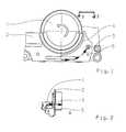
- FIG. 1Schematic front view of the device according to the invention for regulating the oil level in a section of an oil sump that comprises at least two oil sump sections;
- FIG. 2A partial schematic side view of the device according to the invention, along a section line 2-2 of in FIG. 1 , for regulating the oil level in a section of an oil sump that comprises at least two oil sump sections.
- FIGS. 1 and 2show a gearwheel 1 which rotates in the direction indicated by the arrow in a first oil sump section A of a splash-lubricating oil sump, the first oil sump section A being separated from a second oil sump section B by a baffle plate 2 .
- an opening 3is provided in the baffle plate 2 above the oil level desired in the second, adjacent oil sump section B, through which the splashed oil is deflected into the second oil sump section B.
- a preferably curved deflector device 4is provided to deflect the splashed oil, and is positioned directly on the baffle plate 2 under the gearwheel 1 from which the oil is coming. Oil is drawn out of the first oil sump A by the gearwheel, directed radially, and deflected by the deflector device 4 upward and to the side so that it passes through the opening 3 , to the back of the baffle plate 2 and into the adjacent second oil sump section B where, as shown in FIG. 2 , the oil is accommodated and maintained in the second sump section B at a higher oil level than the oil level in the first oil sump section A.
- the direction of movement of the oilis indicated in the figures by the arrows 5 .
Landscapes
- Engineering & Computer Science (AREA)
- General Engineering & Computer Science (AREA)
- Mechanical Engineering (AREA)
- General Details Of Gearings (AREA)
Abstract
Description
- 1 Gearwheel
- 2 Baffle plate
- 3 Opening
- 4 Deflector device
- 5 Oil movement direction
- A First Oil Sump
- B Second Oil Sump
Claims (12)
Applications Claiming Priority (4)
| Application Number | Priority Date | Filing Date | Title |
|---|---|---|---|
| DE102006045240.2 | 2006-09-26 | ||
| DE102006045240 | 2006-09-26 | ||
| DE102006045240ADE102006045240A1 (en) | 2006-09-26 | 2006-09-26 | A method of level control of an oil sump portion of an oil sump having at least two oil sump portions |
| PCT/EP2007/059182WO2008037566A1 (en) | 2006-09-26 | 2007-09-03 | Method for regulating the level of a section of an oil tray comprising at least two sections |
Publications (2)
| Publication Number | Publication Date |
|---|---|
| US20090314580A1 US20090314580A1 (en) | 2009-12-24 |
| US8534425B2true US8534425B2 (en) | 2013-09-17 |
Family
ID=38657011
Family Applications (1)
| Application Number | Title | Priority Date | Filing Date |
|---|---|---|---|
| US12/442,420Active2029-03-02US8534425B2 (en) | 2006-09-26 | 2007-09-03 | Method for regulating the level of a section of an oil tray comprising at least two sections |
Country Status (5)
| Country | Link |
|---|---|
| US (1) | US8534425B2 (en) |
| EP (1) | EP2066926B1 (en) |
| CN (1) | CN101517274B (en) |
| DE (1) | DE102006045240A1 (en) |
| WO (1) | WO2008037566A1 (en) |
Cited By (9)
| Publication number | Priority date | Publication date | Assignee | Title |
|---|---|---|---|---|
| US20130019707A1 (en)* | 2011-01-24 | 2013-01-24 | Tomoyuki Ebihara | Electric transaxle |
| US20130145879A1 (en)* | 2011-12-08 | 2013-06-13 | Aisin Seiki Kabushiki Kaisha | Power transmission device |
| US11320039B2 (en)* | 2018-04-18 | 2022-05-03 | Sumitomo Heavy Industries, Ltd. | Gear device |
| US11525504B2 (en)* | 2018-01-26 | 2022-12-13 | Borgwarner Inc. | Drive train design for electric driven vehicles |
| US20240026965A1 (en)* | 2022-07-21 | 2024-01-25 | Dr. Ing. H.C. F. Porsche Aktiengesellschaft | Transmission device for a motor vehicle |
| US20240110622A1 (en)* | 2021-06-25 | 2024-04-04 | Vitesco Technologies Germany Gmbh | Oil distributor, axle drive and motor vehicle |
| US12129919B2 (en)* | 2022-12-14 | 2024-10-29 | Dana Italia S.R.L. | Systems for lubricant distribution |
| US12215774B2 (en)* | 2022-11-28 | 2025-02-04 | Dana Italia S.R.L. | Systems and methods for gearbox fluid reservoir |
| US12359716B1 (en)* | 2024-03-04 | 2025-07-15 | Fca Us Llc | Electric drive module dual sump arrangement for oil management |
Families Citing this family (11)
| Publication number | Priority date | Publication date | Assignee | Title |
|---|---|---|---|---|
| JP5116805B2 (en)* | 2010-06-08 | 2013-01-09 | ジヤトコ株式会社 | Gear lubrication structure |
| CN103363081B (en)* | 2013-07-10 | 2015-10-28 | 湖南三一路面机械有限公司 | Gear-box and engineering machinery |
| US9470303B2 (en) | 2013-10-08 | 2016-10-18 | Sikorsky Aircraft Corporation | Self scavenging gear shield |
| CN104776191B (en)* | 2015-04-02 | 2017-02-22 | 清华大学 | Method for processing gear model in splash lubrication modeling process |
| US10208848B2 (en)* | 2015-07-29 | 2019-02-19 | GM Global Technology Operations LLC | Gear baffle |
| US10221937B2 (en) | 2016-04-05 | 2019-03-05 | United Technologies Corporation | Slotted oil baffle for gears |
| DE102016207456A1 (en)* | 2016-04-29 | 2017-11-02 | Zf Friedrichshafen Ag | Displacement body in a vehicle transmission |
| US10364880B2 (en) | 2017-01-05 | 2019-07-30 | United Technologies Corporation | Oil quieting direction control baffle |
| US10859152B2 (en)* | 2017-11-13 | 2020-12-08 | Zhejiang Xin Precision Mach Co., Ltd. | Pure electric vehicle transmission with novel lubrication structure |
| DE102018207664A1 (en)* | 2018-05-16 | 2019-11-21 | Zf Friedrichshafen Ag | Oil tank in an automatic transmission of a motor vehicle |
| JP7683557B2 (en)* | 2022-07-12 | 2025-05-27 | トヨタ自動車株式会社 | Lubricating device for vehicle power transmission |
Citations (25)
| Publication number | Priority date | Publication date | Assignee | Title |
|---|---|---|---|---|
| GB222863A (en) | 1923-10-01 | 1925-07-23 | Vickers Electrical Co Ltd | Improvements relating to power transmission mechanism |
| US1554081A (en)* | 1923-03-23 | 1925-09-15 | Gen Electric | Self-oiling gearing |
| DE1047820B (en) | 1954-08-31 | 1958-12-31 | Eisen & Stahlind Ag | Lubricating device for bevel gears in rail vehicles with cardan shaft drive |
| DE1801917A1 (en) | 1968-10-09 | 1970-05-27 | Daimler Benz Ag | Gearbox that works with oil sump lubrication, especially differential gear for the final drive of motor vehicles |
| US3529698A (en)* | 1967-05-05 | 1970-09-22 | Gen Electric | Self-operating lubrication system for gear drive units |
| US4270497A (en)* | 1979-08-22 | 1981-06-02 | Valerio Robert M | Oil pan for internal combustion engines |
| GB2103301A (en) | 1981-06-11 | 1983-02-16 | Gkn Axles | Cooling axle lubricants |
| US4721184A (en)* | 1987-01-28 | 1988-01-26 | Ingersoll-Rand Company | Oil control system |
| US4745816A (en)* | 1985-04-01 | 1988-05-24 | Toyota Jidosha Kabushiki Kaisha | Lubrication mechanism of gear transmission |
| US4938184A (en)* | 1989-09-21 | 1990-07-03 | General Motors Corporation | Engine oil return system |
| US4986235A (en)* | 1989-04-03 | 1991-01-22 | Nissan Motor Co., Ltd. | Oil pan for internal combustion engine |
| DE4321655A1 (en) | 1993-06-30 | 1995-01-12 | Rudolf Stegherr | Device for lubricating high speed gear mechanisms by oil transport brought about by the rotating gearwheels themselves |
| FR2744508A1 (en) | 1996-02-07 | 1997-08-08 | Renault | ARRANGEMENT FOR THE LUBRICATION OF A GEAR TRAIN AND MOTOR VEHICLE GEARBOX COMPRISING SUCH AN ARRANGEMENT |
| DE10034561A1 (en) | 1999-07-21 | 2001-02-01 | Meritor Heavy Vehicle Sys Ltd | Device to control amount of gearbox lubricant in gearbox housing of vehicle has housing with sealed inner section containing lubricant and gearwheel in housing which turns through lubricant, forcing lubricant over wall. |
| DE10032510A1 (en) | 1999-07-12 | 2001-02-08 | Scania Cv Ab | Transmission for heavy vehicle, with oil feed unit for at least one gear wheel pair |
| EP1128095A1 (en) | 2000-02-22 | 2001-08-29 | Eaton Corporation | Gear isolation shroud for transmission |
| US6340012B1 (en)* | 1999-05-07 | 2002-01-22 | Nissan Motor Co., Ltd. | Oil pan for internal combustion engine |
| DE10051356A1 (en) | 2000-10-17 | 2002-04-25 | Daimler Chrysler Ag | Transmission for reciprocating piston engine has oil sump with additional oil reservoir in connection with oil pump, and dry sump circuit for transmission component lubrication |
| DE10260354A1 (en) | 2001-12-21 | 2003-07-17 | Magna Steyr Fahrzeugtechnik Ag | Axle gear with cast housing has seatings for bearings, and vertical partition separating subsidiary and main chambers and openings and transverse ridge |
| DE10223927A1 (en) | 2001-12-28 | 2003-07-17 | Visteon Global Tech Inc | Fluid pump mechanism for use in existing helical gearboxes |
| US20040144597A1 (en) | 2003-01-28 | 2004-07-29 | Frank Metelues | Lubrication arrangement for final drive unit |
| EP1452778A2 (en) | 2003-02-27 | 2004-09-01 | GETRAG Getriebe- und Zahnradfabrik Hermann Hagenmeyer GmbH & Cie KG | Automated gearbox for motor vehicles |
| WO2005059409A1 (en) | 2003-12-17 | 2005-06-30 | Deere & Company | Gearbox arrangement for a vehicle |
| US20060063633A1 (en) | 2004-09-23 | 2006-03-23 | Turner Gary A | Enhanced lubrication system for drive axle assemblies |
| US7213682B2 (en)* | 2003-11-19 | 2007-05-08 | General Motors Corporation | Hydraulic fluid storage apparatus for a transmission |
Family Cites Families (1)
| Publication number | Priority date | Publication date | Assignee | Title |
|---|---|---|---|---|
| CN2549265Y (en)* | 2002-06-25 | 2003-05-07 | 荆州市巨鲸传动机械有限公司 | Three stage planet-gear speed reducer with complete internal lubrication |
- 2006
- 2006-09-26DEDE102006045240Apatent/DE102006045240A1/ennot_activeWithdrawn
- 2007
- 2007-09-03EPEP07803168Apatent/EP2066926B1/ennot_activeNot-in-force
- 2007-09-03CNCN2007800357337Apatent/CN101517274B/ennot_activeExpired - Fee Related
- 2007-09-03USUS12/442,420patent/US8534425B2/enactiveActive
- 2007-09-03WOPCT/EP2007/059182patent/WO2008037566A1/enactiveApplication Filing
Patent Citations (30)
| Publication number | Priority date | Publication date | Assignee | Title |
|---|---|---|---|---|
| US1554081A (en)* | 1923-03-23 | 1925-09-15 | Gen Electric | Self-oiling gearing |
| GB222863A (en) | 1923-10-01 | 1925-07-23 | Vickers Electrical Co Ltd | Improvements relating to power transmission mechanism |
| DE1047820B (en) | 1954-08-31 | 1958-12-31 | Eisen & Stahlind Ag | Lubricating device for bevel gears in rail vehicles with cardan shaft drive |
| US3529698A (en)* | 1967-05-05 | 1970-09-22 | Gen Electric | Self-operating lubrication system for gear drive units |
| DE1801917A1 (en) | 1968-10-09 | 1970-05-27 | Daimler Benz Ag | Gearbox that works with oil sump lubrication, especially differential gear for the final drive of motor vehicles |
| US4270497A (en)* | 1979-08-22 | 1981-06-02 | Valerio Robert M | Oil pan for internal combustion engines |
| GB2103301A (en) | 1981-06-11 | 1983-02-16 | Gkn Axles | Cooling axle lubricants |
| US4745816A (en)* | 1985-04-01 | 1988-05-24 | Toyota Jidosha Kabushiki Kaisha | Lubrication mechanism of gear transmission |
| US4721184A (en)* | 1987-01-28 | 1988-01-26 | Ingersoll-Rand Company | Oil control system |
| US4986235A (en)* | 1989-04-03 | 1991-01-22 | Nissan Motor Co., Ltd. | Oil pan for internal combustion engine |
| US4938184A (en)* | 1989-09-21 | 1990-07-03 | General Motors Corporation | Engine oil return system |
| DE4321655A1 (en) | 1993-06-30 | 1995-01-12 | Rudolf Stegherr | Device for lubricating high speed gear mechanisms by oil transport brought about by the rotating gearwheels themselves |
| FR2744508A1 (en) | 1996-02-07 | 1997-08-08 | Renault | ARRANGEMENT FOR THE LUBRICATION OF A GEAR TRAIN AND MOTOR VEHICLE GEARBOX COMPRISING SUCH AN ARRANGEMENT |
| US6340012B1 (en)* | 1999-05-07 | 2002-01-22 | Nissan Motor Co., Ltd. | Oil pan for internal combustion engine |
| DE10032510A1 (en) | 1999-07-12 | 2001-02-08 | Scania Cv Ab | Transmission for heavy vehicle, with oil feed unit for at least one gear wheel pair |
| US6299561B1 (en)* | 1999-07-21 | 2001-10-09 | Meritor Heavy Vehicle Systems, Llc | Device for controlling level of gear lubricant as a function of speed |
| DE10034561A1 (en) | 1999-07-21 | 2001-02-01 | Meritor Heavy Vehicle Sys Ltd | Device to control amount of gearbox lubricant in gearbox housing of vehicle has housing with sealed inner section containing lubricant and gearwheel in housing which turns through lubricant, forcing lubricant over wall. |
| US6374951B1 (en) | 2000-02-22 | 2002-04-23 | Eaton Corporation | Gear isolation shroud for transmission |
| EP1128095A1 (en) | 2000-02-22 | 2001-08-29 | Eaton Corporation | Gear isolation shroud for transmission |
| US6644439B2 (en) | 2000-10-17 | 2003-11-11 | Daimlerchrysler Ag | Transmission for an internal combustion engine |
| DE10051356A1 (en) | 2000-10-17 | 2002-04-25 | Daimler Chrysler Ag | Transmission for reciprocating piston engine has oil sump with additional oil reservoir in connection with oil pump, and dry sump circuit for transmission component lubrication |
| DE10260354A1 (en) | 2001-12-21 | 2003-07-17 | Magna Steyr Fahrzeugtechnik Ag | Axle gear with cast housing has seatings for bearings, and vertical partition separating subsidiary and main chambers and openings and transverse ridge |
| DE10223927A1 (en) | 2001-12-28 | 2003-07-17 | Visteon Global Tech Inc | Fluid pump mechanism for use in existing helical gearboxes |
| US6616432B2 (en)* | 2001-12-28 | 2003-09-09 | Visteon Global Technologies, Inc. | Fluid pump mechanism for use in existing helical gearsets |
| US20040144597A1 (en) | 2003-01-28 | 2004-07-29 | Frank Metelues | Lubrication arrangement for final drive unit |
| DE102004004079A1 (en) | 2003-01-28 | 2004-08-05 | Dana Corp., Toledo | Endachsenantriebseinheit |
| EP1452778A2 (en) | 2003-02-27 | 2004-09-01 | GETRAG Getriebe- und Zahnradfabrik Hermann Hagenmeyer GmbH & Cie KG | Automated gearbox for motor vehicles |
| US7213682B2 (en)* | 2003-11-19 | 2007-05-08 | General Motors Corporation | Hydraulic fluid storage apparatus for a transmission |
| WO2005059409A1 (en) | 2003-12-17 | 2005-06-30 | Deere & Company | Gearbox arrangement for a vehicle |
| US20060063633A1 (en) | 2004-09-23 | 2006-03-23 | Turner Gary A | Enhanced lubrication system for drive axle assemblies |
Cited By (13)
| Publication number | Priority date | Publication date | Assignee | Title |
|---|---|---|---|---|
| US20130019707A1 (en)* | 2011-01-24 | 2013-01-24 | Tomoyuki Ebihara | Electric transaxle |
| US8899381B2 (en)* | 2011-01-24 | 2014-12-02 | Kanzaki Kokyukoki Mfg. Co., Ltd. | Electric transaxle |
| US20130145879A1 (en)* | 2011-12-08 | 2013-06-13 | Aisin Seiki Kabushiki Kaisha | Power transmission device |
| US11525504B2 (en)* | 2018-01-26 | 2022-12-13 | Borgwarner Inc. | Drive train design for electric driven vehicles |
| US11320039B2 (en)* | 2018-04-18 | 2022-05-03 | Sumitomo Heavy Industries, Ltd. | Gear device |
| US20240110622A1 (en)* | 2021-06-25 | 2024-04-04 | Vitesco Technologies Germany Gmbh | Oil distributor, axle drive and motor vehicle |
| US12331827B2 (en)* | 2021-06-25 | 2025-06-17 | Vitesco Technologies Germany Gmbh | Oil distributor, axle drive and motor vehicle |
| US20240026965A1 (en)* | 2022-07-21 | 2024-01-25 | Dr. Ing. H.C. F. Porsche Aktiengesellschaft | Transmission device for a motor vehicle |
| US12429127B2 (en)* | 2022-07-21 | 2025-09-30 | Dr. Ing. H.C. F. Porsche Aktiengesellschaft | Transmission device for a motor vehicle |
| US12215774B2 (en)* | 2022-11-28 | 2025-02-04 | Dana Italia S.R.L. | Systems and methods for gearbox fluid reservoir |
| US12129919B2 (en)* | 2022-12-14 | 2024-10-29 | Dana Italia S.R.L. | Systems for lubricant distribution |
| US20240401690A1 (en)* | 2022-12-14 | 2024-12-05 | Dana Italia S.R.L. | Systems for lubricant distribution |
| US12359716B1 (en)* | 2024-03-04 | 2025-07-15 | Fca Us Llc | Electric drive module dual sump arrangement for oil management |
Also Published As
| Publication number | Publication date |
|---|---|
| WO2008037566A1 (en) | 2008-04-03 |
| EP2066926A1 (en) | 2009-06-10 |
| CN101517274B (en) | 2012-11-28 |
| EP2066926B1 (en) | 2011-06-29 |
| DE102006045240A1 (en) | 2008-04-03 |
| US20090314580A1 (en) | 2009-12-24 |
| CN101517274A (en) | 2009-08-26 |
Similar Documents
| Publication | Publication Date | Title |
|---|---|---|
| US8534425B2 (en) | Method for regulating the level of a section of an oil tray comprising at least two sections | |
| EP1635090B1 (en) | Oil discharge structure | |
| US6223858B1 (en) | Transmission lubricating device | |
| DE102009010282B4 (en) | Dry sump oil tank assembly for a vehicle | |
| CN107387735B (en) | Lightweight gearbox body with automatic lubricating oil collection and distribution function | |
| JP5920235B2 (en) | Vehicle drive device | |
| JP7119784B2 (en) | transmission oil gutter | |
| CN102494115A (en) | Bearing lubricating structure of driving gear shaft of gear box for urban rail traffic vehicle | |
| JP2017502233A (en) | Vehicle power transmission unit (PTU) with oiling path | |
| CN103307262A (en) | Final decelerator | |
| CN110088508A (en) | For guiding the device of lubricating oil in the hollow shaft of gearbox | |
| US5725072A (en) | Speed change gear device with lubricating auxiliary vessel | |
| DE102010010411A1 (en) | Gear box i.e. axle gear box, for conducting drive torque of engine to e.g. front drive axle of wheels of motor car, has gear wheel for carrying lubrication oil that is conducted from lubricant reservoir to gear box locations over channels | |
| CN107208777B (en) | Oil groove and the speed changer for having the oil groove | |
| CN109973635B (en) | Oil injection and splash mixed lubrication system of integral high-speed gear box | |
| ES2221349T3 (en) | LUBRICATION DEVICE FOR REDUCER OF SEVERAL STAGES. | |
| CN204004339U (en) | Retarder and bearing lubrication thereof and cooling unit | |
| CN211474848U (en) | Oil collecting baffle of gear | |
| JP2013167296A (en) | Lubricating structure of rotary electric machine | |
| CN108351018A (en) | Oil guide boots and transmissions equipped with oil guide boots | |
| JP3693566B2 (en) | Lubrication structure of differential gear | |
| CN203239418U (en) | Lower crank case oil baffle plate | |
| JP2021162136A (en) | Lubricating structure of transmission | |
| RU2776432C2 (en) | Gearbox for agricultural working machine and agricultural working machine | |
| TWI863221B (en) | Vehicle crankcase device |
Legal Events
| Date | Code | Title | Description |
|---|---|---|---|
| AS | Assignment | Owner name:ZF FRIEDRICHSHAFEN AG, GERMANY Free format text:ASSIGNMENT OF ASSIGNORS INTEREST;ASSIGNORS:GLUCK, MARTIN;JABS, SVEN;REEL/FRAME:022453/0587;SIGNING DATES FROM 20090204 TO 20090206 Owner name:ZF FRIEDRICHSHAFEN AG, GERMANY Free format text:ASSIGNMENT OF ASSIGNORS INTEREST;ASSIGNORS:GLUCK, MARTIN;JABS, SVEN;SIGNING DATES FROM 20090204 TO 20090206;REEL/FRAME:022453/0587 | |
| AS | Assignment | Owner name:ZF FRIEDRICHSHAFEN AG, GERMANY Free format text:ASSIGNMENT OF ASSIGNORS INTEREST;ASSIGNOR:ZF FRIEDRICHSHAFEN AG;REEL/FRAME:025200/0194 Effective date:20101021 Owner name:DR. ING. H.C. F. PORSCHE AKTIENGESELLSCHAFT, GERMA Free format text:ASSIGNMENT OF ASSIGNORS INTEREST;ASSIGNOR:ZF FRIEDRICHSHAFEN AG;REEL/FRAME:025200/0194 Effective date:20101021 | |
| FEPP | Fee payment procedure | Free format text:PAYOR NUMBER ASSIGNED (ORIGINAL EVENT CODE: ASPN); ENTITY STATUS OF PATENT OWNER: LARGE ENTITY | |
| STCF | Information on status: patent grant | Free format text:PATENTED CASE | |
| FEPP | Fee payment procedure | Free format text:PAYER NUMBER DE-ASSIGNED (ORIGINAL EVENT CODE: RMPN); ENTITY STATUS OF PATENT OWNER: LARGE ENTITY Free format text:PAYOR NUMBER ASSIGNED (ORIGINAL EVENT CODE: ASPN); ENTITY STATUS OF PATENT OWNER: LARGE ENTITY | |
| FPAY | Fee payment | Year of fee payment:4 | |
| MAFP | Maintenance fee payment | Free format text:PAYMENT OF MAINTENANCE FEE, 8TH YEAR, LARGE ENTITY (ORIGINAL EVENT CODE: M1552); ENTITY STATUS OF PATENT OWNER: LARGE ENTITY Year of fee payment:8 | |
| FEPP | Fee payment procedure | Free format text:MAINTENANCE FEE REMINDER MAILED (ORIGINAL EVENT CODE: REM.); ENTITY STATUS OF PATENT OWNER: LARGE ENTITY |