US8534079B2 - Freezer with liquid cryogen refrigerant and method - Google Patents
Freezer with liquid cryogen refrigerant and methodDownload PDFInfo
- Publication number
- US8534079B2 US8534079B2US12/726,910US72691010AUS8534079B2US 8534079 B2US8534079 B2US 8534079B2US 72691010 AUS72691010 AUS 72691010AUS 8534079 B2US8534079 B2US 8534079B2
- Authority
- US
- United States
- Prior art keywords
- purge
- heat exchanger
- line
- storage chamber
- exhaust
- Prior art date
- Legal status (The legal status is an assumption and is not a legal conclusion. Google has not performed a legal analysis and makes no representation as to the accuracy of the status listed.)
- Active - Reinstated, expires
Links
- 239000007788liquidSubstances0.000titleclaimsabstractdescription67
- 239000003507refrigerantSubstances0.000titleclaimsabstractdescription30
- 238000000034methodMethods0.000titledescription3
- 238000010926purgeMethods0.000claimsabstractdescription81
- 238000004891communicationMethods0.000claimsabstractdescription35
- 238000009413insulationMethods0.000claimsabstractdescription14
- 230000015572biosynthetic processEffects0.000claimsabstractdescription6
- 239000007789gasSubstances0.000claimsdescription64
- IJGRMHOSHXDMSA-UHFFFAOYSA-NAtomic nitrogenChemical compoundN#NIJGRMHOSHXDMSA-UHFFFAOYSA-N0.000claimsdescription44
- 238000001816coolingMethods0.000claimsdescription28
- 229910052757nitrogenInorganic materials0.000claimsdescription21
- 238000005057refrigerationMethods0.000description5
- 239000003570airSubstances0.000description3
- 238000004378air conditioningMethods0.000description2
- 229910001873dinitrogenInorganic materials0.000description2
- 239000011152fibreglassSubstances0.000description2
- 239000011494foam glassSubstances0.000description2
- 239000000463materialSubstances0.000description2
- 238000012546transferMethods0.000description2
- 230000008016vaporizationEffects0.000description2
- 239000012080ambient airSubstances0.000description1
- 239000012620biological materialSubstances0.000description1
- 238000010276constructionMethods0.000description1
- 239000000112cooling gasSubstances0.000description1
- 238000012864cross contaminationMethods0.000description1
- 230000001419dependent effectEffects0.000description1
- 238000007599dischargingMethods0.000description1
- 239000012774insulation materialSubstances0.000description1
- 238000012986modificationMethods0.000description1
- 230000004048modificationEffects0.000description1
- 238000012545processingMethods0.000description1
- 238000013022ventingMethods0.000description1
- XLYOFNOQVPJJNP-UHFFFAOYSA-NwaterSubstancesOXLYOFNOQVPJJNP-UHFFFAOYSA-N0.000description1
Images

Classifications
- F—MECHANICAL ENGINEERING; LIGHTING; HEATING; WEAPONS; BLASTING
- F25—REFRIGERATION OR COOLING; COMBINED HEATING AND REFRIGERATION SYSTEMS; HEAT PUMP SYSTEMS; MANUFACTURE OR STORAGE OF ICE; LIQUEFACTION SOLIDIFICATION OF GASES
- F25D—REFRIGERATORS; COLD ROOMS; ICE-BOXES; COOLING OR FREEZING APPARATUS NOT OTHERWISE PROVIDED FOR
- F25D3/00—Devices using other cold materials; Devices using cold-storage bodies
- F25D3/10—Devices using other cold materials; Devices using cold-storage bodies using liquefied gases, e.g. liquid air
- F25D3/105—Movable containers
- F—MECHANICAL ENGINEERING; LIGHTING; HEATING; WEAPONS; BLASTING
- F25—REFRIGERATION OR COOLING; COMBINED HEATING AND REFRIGERATION SYSTEMS; HEAT PUMP SYSTEMS; MANUFACTURE OR STORAGE OF ICE; LIQUEFACTION SOLIDIFICATION OF GASES
- F25D—REFRIGERATORS; COLD ROOMS; ICE-BOXES; COOLING OR FREEZING APPARATUS NOT OTHERWISE PROVIDED FOR
- F25D21/00—Defrosting; Preventing frosting; Removing condensed or defrost water
- F25D21/04—Preventing the formation of frost or condensate
- F—MECHANICAL ENGINEERING; LIGHTING; HEATING; WEAPONS; BLASTING
- F25—REFRIGERATION OR COOLING; COMBINED HEATING AND REFRIGERATION SYSTEMS; HEAT PUMP SYSTEMS; MANUFACTURE OR STORAGE OF ICE; LIQUEFACTION SOLIDIFICATION OF GASES
- F25D—REFRIGERATORS; COLD ROOMS; ICE-BOXES; COOLING OR FREEZING APPARATUS NOT OTHERWISE PROVIDED FOR
- F25D21/00—Defrosting; Preventing frosting; Removing condensed or defrost water
- F25D21/06—Removing frost
- F25D21/10—Removing frost by spraying with fluid
- F—MECHANICAL ENGINEERING; LIGHTING; HEATING; WEAPONS; BLASTING
- F25—REFRIGERATION OR COOLING; COMBINED HEATING AND REFRIGERATION SYSTEMS; HEAT PUMP SYSTEMS; MANUFACTURE OR STORAGE OF ICE; LIQUEFACTION SOLIDIFICATION OF GASES
- F25D—REFRIGERATORS; COLD ROOMS; ICE-BOXES; COOLING OR FREEZING APPARATUS NOT OTHERWISE PROVIDED FOR
- F25D29/00—Arrangement or mounting of control or safety devices
- F25D29/001—Arrangement or mounting of control or safety devices for cryogenic fluid systems
- G—PHYSICS
- G01—MEASURING; TESTING
- G01N—INVESTIGATING OR ANALYSING MATERIALS BY DETERMINING THEIR CHEMICAL OR PHYSICAL PROPERTIES
- G01N1/00—Sampling; Preparing specimens for investigation
- G01N1/28—Preparing specimens for investigation including physical details of (bio-)chemical methods covered elsewhere, e.g. G01N33/50, C12Q
- G01N1/42—Low-temperature sample treatment, e.g. cryofixation
- F—MECHANICAL ENGINEERING; LIGHTING; HEATING; WEAPONS; BLASTING
- F25—REFRIGERATION OR COOLING; COMBINED HEATING AND REFRIGERATION SYSTEMS; HEAT PUMP SYSTEMS; MANUFACTURE OR STORAGE OF ICE; LIQUEFACTION SOLIDIFICATION OF GASES
- F25D—REFRIGERATORS; COLD ROOMS; ICE-BOXES; COOLING OR FREEZING APPARATUS NOT OTHERWISE PROVIDED FOR
- F25D2700/00—Means for sensing or measuring; Sensors therefor
- F25D2700/12—Sensors measuring the inside temperature
Definitions
- the present inventiongenerally relates to freezers and, more particularly, to freezers that use liquid cryogen as a refrigerant.
- Freezers for storing biological specimens, samples, materials, products and the likeoften use cryogenic liquids as a refrigerant.
- Such freezerstypically feature a reservoir of a liquid cryogen, such as liquid nitrogen, in the bottom of the freezer storage chamber with the product stored above the reservoir or partly submerged with in the cryogenic liquid.
- the freezerstypically also feature a double-walled, vacuum insulated construction so that the storage chamber is well insulated.
- Such freezersprovide storage temperatures ranging from approximately ⁇ 90° C. to ⁇ 195° C.
- a disadvantage of prior art liquid cryogen freezersis that the temperature cannot be directly controlled.
- the temperatureis controlled by maintaining the amount of cryogenic liquid in the reservoir.
- the temperature of the freezer storage compartmentthus varies dependent upon the amount of liquid cryogen in the freezer.
- a further disadvantage of prior art liquid cryogen freezersis that there is some concern that submerging biological specimens in the cryogenic liquid presents a risk of cross-contamination between specimen containers. Even when the stored specimen containers are placed in the cold vapor above the cryogenic liquid reservoir, there is still the potential for the specimen containers to come into contact with, or be submerged within, the cryogenic liquid if the freezer is overfilled with the cryogenic liquid.
- freezersthat use mechanical refrigeration systems in place of a liquid cryogen reservoir.
- the mechanical refrigeration systemstypically include a compressor, an evaporator, a condenser and a fan. Air is circulated through the storage chamber and across a cooling coil to maintain the desired temperature in the freezer storage chamber.
- the freezersnormally do not feature vacuum insulation and employ materials such as foam and/or fiberglass insulation to insulate the storage chamber. Such freezers typically provide storage temperatures in the ⁇ 40° C. to ⁇ 80° C. range.
- a disadvantage of the mechanical freezeris that the mechanical refrigeration system requires a significant amount of electrical power to maintain the desired temperature within the freezer storage chamber. Furthermore, mechanical refrigeration systems remove heat from the storage chamber and reject it to the environment around the freezer. This adds significant heat to the room within which the freezer is stored so that additional air conditioning capacity is required for the room. This adds additional electrical power requirements to the facility. In addition, in the event of a power failure, the storage chamber will warm rapidly, which could result in the loss of the stored biological materials.
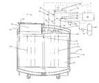
- FIG. 1is a schematic of an embodiment of the freezer with liquid cryogen refrigerant of the present invention
- FIG. 2is a flow chart showing the processing performed by the controller of FIG. 1 .
- FIG. 1An embodiment of the freezer with liquid cryogen refrigerant of the invention is indicated in general at 10 in FIG. 1 .
- the freezerincludes an inner vessel 12 which defines storage chamber 14 .
- An outer jacket 16generally surrounds the vessel 12 so that an insulation space 18 is defined between the inner vessel 12 and the outer jacket 16 .
- a vacuumis preferably drawn on the insulation space 18 so that the storage chamber 14 is insulated.
- the vacuum insulation space 18may be supplemented, or replaced, by insulation materials known in the art including, but not limited to, foam or fiberglass.
- An insulated plug or lid 20is removably positioned within an offset access opening 22 of the freezer which permits access to the storage chamber 14 .
- the lid 20is preferably mounted to the remaining portion of the freezer by hinged bracket 24 .
- a rotating tray 26is positioned within the storage chamber 14 and holds the items being stored while also providing access through offset access opening 22 when the lid 20 is open.
- the storage chamber 14 of the freezer, and thus the items stored therein,are cooled by a heat exchanger positioned within a top portion of the storage chamber.
- the heat exchangerpreferably takes the form of a cooling coil 28 , but alternative heat exchanger components or structures could be used instead.
- a storage container 29 containing a supply of liquid cryogen refrigerantis in communication with the inlet 30 of feed line 32 .
- Feed line 32communicates with the inlet of cooling coil 28 .
- liquid nitrogenis discussed below as the liquid cryogen refrigerant, it should be understood that alternative cryogenic liquids could be substituted for the liquid nitrogen.
- the liquid nitrogenis pressurized for transfer to the inlet 30 of the feed line 32 such as by a pump 33 .
- the liquid nitrogencould be stored under pressure in storage container 29 so that no pump is needed.
- Other alternatives for supplying cryogenic liquid under pressureare known in the art and may be used as well.
- Controller 34may be a microprocessor or any other electronic control device known in the art. As illustrated by block 43 of FIG. 2 , the controller 34 of FIG. 1 opens the automated bypass valve 42 so that liquid nitrogen flows through the inlet 30 of feed line 32 .
- bypass line 38having an outlet 40 also communicates with a portion of the feed line 32 positioned between the inlet of the cooling coil 28 and the inlet 30 of the feed line.
- the temperature of the gas entering the feed line 32is monitored by feed temperature sensor 44 , which also communicates with controller 34 .
- controller 34When the temperature of the incoming gas (indicated as T G in decision block 45 of FIG. 2 ) has cooled to a temperature below that of the freezer storage chamber 14 (indicated as T CH in decision block 45 of FIG. 2 ), the controller closes bypass valve 42 and a purge gas valve 46 is opened, as indicated at 48 and 50 , respectively, in FIG. 2 .
- liquid nitrogen refrigerantflows through the cooling coil 28 .
- the liquid nitrogen flowing through the cooling coilis colder than the gas inside of storage chamber 14 so that it absorbs heat from inside of the chamber. As the liquid nitrogen absorbs the heat, it is vaporized and exits the heat exchanger taking the absorbed heat with it.
- the resulting cold gas surrounding the heat exchanger inside the storage chambercirculates throughout the chamber via natural convection. More specifically, the higher density cold gas from the top portion of the chamber within which the cooling coil is positioned descends (arrows 51 a ) thus forcing warmer lower density gas to rise (arrows 51 b ) to be cooled by the cooling coil.
- the open purge gas valve 46is positioned on the outlet side of the heat exchanger.
- the vaporized nitrogen refrigerantexits the outlet of the heat exchanger through exit line 52 and travels into purge line 54 , since exhaust valve 56 is in a closed condition.
- Purge line 54is provided with purge outlets 62 positioned adjacent to and over the cooling coil so that the nitrogen gas exits the purge line as a purge gas and provides additional cooling to the storage chamber 14 .
- ice formation on the exterior surface of the cooling coil 28can insulate it from the storage chamber of the freezer and reduce the coil's cooling effectiveness.
- the nitrogen purge gas exiting the purge outlets 62 above the cooling coil 28is a dry gas. This dry nitrogen purge gas displaces ambient air (which could contain water) from the space around the exterior surface of the cooling coil to reduce the possibility of ice forming on the coil.
- the purgetypically continues until a sufficient amount of dry nitrogen purge gas is introduced to the chamber to displace any moist air in the chamber.
- the controller 34monitors the temperature of the purge gas via a purge gas temperature sensor 64 .
- T P in decision block 66 of FIG. 2the temperature of the purge gas traveling through purge line 54 is cooled to the minimum desired temperature of the storage chamber of the freezer (indicated as T Dmin in decision block 66 of FIG. 2 )
- the purge gas valve 46is closed by the controller 34 , as indicated at 72 in FIG. 2 .
- the cooling gas exhaust valve 56is opened by the controller 34 , as indicated at 73 in FIG. 2 , to vent nitrogen gas from the cooling coil external to the freezer via the exhaust line 74 and exhaust vent 76 .
- the cooling coil 28is at a temperature less than that of the gas inside of the storage chamber 14 , convection cooling will occur.
- the controller 34monitors the exhaust gas temperature via an exhaust gas temperature sensor 82 .
- T E in decision block 78 of FIG. 2the temperature of the nitrogen exhaust gas flowing through exit line 52 and exhaust line 74 (indicated as T E in decision block 78 of FIG. 2 ) cools to a temperature approximately 10° C. to 20° C. below the minimum desired storage chamber temperature of the storage chamber (indicated as T Dmin ⁇ X in decision block 78 of FIG. 2 )
- the exhaust valve 56is closed by the controller, as indicated at 84 in FIG. 2 , so that the flow of liquid nitrogen into the cooling coil is paused.
- the nitrogen (liquid or gaseous) in the cooling coilthen absorbs heat from the chamber and expands or evaporates so that no-flow cooling is accomplished.
- the predetermined amount X above and in decision block 78 of FIG. 2is preferably approximately 10° C. to 20° C., alternative temperature amounts may be used instead.
- the exhaust gas temperature sensor 82is positioned external to the freezer. As a result, it is warmed by ambient external air while there is no flow through the cooling coil 28 . Once the exhaust gas temperature sensor detects that the gas within line 52 has warmed above the maximum desired storage chamber temperature (indicated as T Dmax in decision block 86 of FIG. 2 ), the exhaust valve 56 is again opened by the controller.
- the exhaust valve 56is cycled in accordance with the above until the freezer storage chamber 14 cools to the minimum desired temperature as measured by a chamber temperature sensor 92 . At that time, as indicated at decision block 94 , all valves are closed and the controller simply monitors the storage chamber temperature.
- the freezer of FIGS. 1 and 2therefore removes heat from the storage chamber by vaporizing the liquid nitrogen in the cooling coil and then venting the gas outside of the freezer, and outside of the room within which the freezer is located, if desired.
- the gas created by vaporizing the liquid nitrogencan only be warmed to the temperature of the freezer storage chamber instead of above ambient as is the case with the refrigerant of a typical prior art mechanical freezer. As a result, no heat is added to the room within which the freezer is located to increase the air conditioning required for the room.
- the freezer of FIGS. 1 and 2also allows for control of the freezer temperature, not possible with typical prior art liquid cryogen freezers, without the disadvantages of a mechanical freezer.
- the freezer of FIGS. 1 and 2prevents the stored product from making contact with and/or being submerged within the liquid cryogen by removing the liquid cryogen from the storage chamber of the freezer.
- the freezer of FIGS. 1 and 2also eliminates the mechanical refrigeration components used by typical prior art mechanical freezers and thus the associated large electrical power requirements. Minimal power is required by the freezer of FIGS. 1 and 2 to operate the controller that monitors and controls the freezer and the associated solenoid valves required for operation.
- the freezer of FIGS. 1 and 2is not immediately effected. Since the freezer incorporates a vacuum-insulated storage chamber, the storage chamber temperature is maintained over a longer period of time, thus requiring infrequent cooling cycles as opposed to the continuous cooling required by typical prior art mechanical freezers. This provides sufficient time to address power failure issues before the storage temperature inside the freezer is effected.
Landscapes
- Engineering & Computer Science (AREA)
- Chemical & Material Sciences (AREA)
- Physics & Mathematics (AREA)
- Combustion & Propulsion (AREA)
- Mechanical Engineering (AREA)
- Thermal Sciences (AREA)
- General Engineering & Computer Science (AREA)
- Life Sciences & Earth Sciences (AREA)
- Health & Medical Sciences (AREA)
- Analytical Chemistry (AREA)
- Biochemistry (AREA)
- General Health & Medical Sciences (AREA)
- General Physics & Mathematics (AREA)
- Immunology (AREA)
- Pathology (AREA)
- Devices That Are Associated With Refrigeration Equipment (AREA)
- Filling Or Discharging Of Gas Storage Vessels (AREA)
Abstract
Description
Claims (22)
Priority Applications (5)
| Application Number | Priority Date | Filing Date | Title |
|---|---|---|---|
| US12/726,910US8534079B2 (en) | 2010-03-18 | 2010-03-18 | Freezer with liquid cryogen refrigerant and method |
| JP2011056795AJP5806486B2 (en) | 2010-03-18 | 2011-03-15 | Freezer and method using liquid cryogen refrigerant |
| EP11250313.1AEP2372274B1 (en) | 2010-03-18 | 2011-03-16 | Freezer with liquid cryogen refrigerant and method |
| KR1020110023820AKR101797242B1 (en) | 2010-03-18 | 2011-03-17 | Freezer with liquid cryogen refrigerant and method |
| CN201110065907.2ACN102192626B (en) | 2010-03-18 | 2011-03-18 | Freezer with liquid cryogen refrigerant and method |
Applications Claiming Priority (1)
| Application Number | Priority Date | Filing Date | Title |
|---|---|---|---|
| US12/726,910US8534079B2 (en) | 2010-03-18 | 2010-03-18 | Freezer with liquid cryogen refrigerant and method |
Publications (2)
| Publication Number | Publication Date |
|---|---|
| US20110225984A1 US20110225984A1 (en) | 2011-09-22 |
| US8534079B2true US8534079B2 (en) | 2013-09-17 |
Family
ID=44123236
Family Applications (1)
| Application Number | Title | Priority Date | Filing Date |
|---|---|---|---|
| US12/726,910Active - Reinstated2031-03-03US8534079B2 (en) | 2010-03-18 | 2010-03-18 | Freezer with liquid cryogen refrigerant and method |
Country Status (5)
| Country | Link |
|---|---|
| US (1) | US8534079B2 (en) |
| EP (1) | EP2372274B1 (en) |
| JP (1) | JP5806486B2 (en) |
| KR (1) | KR101797242B1 (en) |
| CN (1) | CN102192626B (en) |
Cited By (3)
| Publication number | Priority date | Publication date | Assignee | Title |
|---|---|---|---|---|
| US20160276187A1 (en)* | 2015-03-20 | 2016-09-22 | Gudeng Precision Industrial Co., Ltd | Operating methods of purge devices for containers |
| WO2023003611A1 (en)* | 2021-07-20 | 2023-01-26 | Corey John A | Dual-mode ultralow and/or cryogenic temperature storage device |
| US11566834B2 (en) | 2019-05-13 | 2023-01-31 | Abt Holding Company | Apparatus and method for cryostorage and manipulation of a plurality of container units |
Families Citing this family (12)
| Publication number | Priority date | Publication date | Assignee | Title |
|---|---|---|---|---|
| CN103271764B (en)* | 2013-06-09 | 2015-01-07 | 山东大学 | Liquid nitrogen spraying beam flow and stability accurately controlled device |
| EP3325978B1 (en)* | 2015-07-20 | 2024-01-24 | Azenta US, Inc. | Automated vault module |
| CN105737471B (en)* | 2016-02-04 | 2018-08-31 | 上海理工大学 | Quickly cooling portable biometric sample Cord blood case |
| CN106196878A (en)* | 2016-08-04 | 2016-12-07 | 航天新长征电动汽车技术有限公司 | A kind of refrigerating device and liquid nitrogen refrigerating method thereof |
| US10330378B2 (en)* | 2017-09-19 | 2019-06-25 | Reflect Scientific Inc. | Freezer with remote management |
| JP7115836B2 (en) | 2017-11-07 | 2022-08-09 | エム・ブイ・イー・バイオロジカル・ソリューションズ・ユー・エス・リミテッド・ライアビリティ・カンパニー | cryogenic refrigerator |
| KR20240172232A (en)* | 2018-05-20 | 2024-12-09 | 아베야테크, 엘엘씨 | Cryogenic storage unit |
| CN109764594B (en)* | 2019-01-29 | 2020-07-14 | 成都航空职业技术学院 | Low-temperature freezing treatment device |
| CN112780203A (en)* | 2021-01-29 | 2021-05-11 | 西南石油大学 | Device for continuously cooling deep high-temperature drilling fluid by using cooling fluid |
| KR102703483B1 (en)* | 2022-02-17 | 2024-09-06 | 에스케이하이닉스 주식회사 | Cooling device and method of operating cooling device |
| KR102792442B1 (en)* | 2022-09-20 | 2025-04-09 | (주)에코엔테크 | Smart liquid nitrogen box |
| CN115751815B (en)* | 2022-11-22 | 2024-01-19 | 杭州爱唯生命科技有限公司 | Multi-temperature storage liquid nitrogen refrigerator and switching method |
Citations (31)
| Publication number | Priority date | Publication date | Assignee | Title |
|---|---|---|---|---|
| US2007251A (en)* | 1934-04-14 | 1935-07-09 | Atmospheric Nitrogen Corp | Process and apparatus for dispensing measured quantities of liquefied gas |
| US3166913A (en)* | 1962-07-30 | 1965-01-26 | Elmwood Liquid Products Inc | Method for refrigerating |
| US3640082A (en) | 1970-06-08 | 1972-02-08 | Hughes Aircraft Co | Cryogenic refrigerator cycle |
| US3782133A (en)* | 1972-08-14 | 1974-01-01 | Air Liquide | Low temperature storage vessel |
| US4277949A (en) | 1979-06-22 | 1981-07-14 | Air Products And Chemicals, Inc. | Cryostat with serviceable refrigerator |
| US4317665A (en) | 1980-12-22 | 1982-03-02 | Air Products And Chemicals, Inc. | Cryogenic freezing system |
| US4343634A (en)* | 1981-03-23 | 1982-08-10 | Union Carbide Corporation | Process for operating a fluidized bed |
| US4344291A (en) | 1980-04-28 | 1982-08-17 | Liquid Carbonic Corporation | Cryogenic cabinet freezer |
| US4528819A (en) | 1984-05-08 | 1985-07-16 | Air Products And Chemicals, Inc. | Exhaust control for cryogenic freezer |
| US4621500A (en)* | 1984-10-18 | 1986-11-11 | Conterm International Terminals, Inc. | Refrigeration system |
| US4739623A (en) | 1987-06-11 | 1988-04-26 | Liquid Carbonic Corporation | Liquid cryogen freezer and method of operating same |
| US4991402A (en)* | 1987-11-12 | 1991-02-12 | Saia Iii Louis P | Portable self-contained cooler/freezer apparatus for use on common carrier type unrefrigerated truck lines and the like |
| US5327729A (en)* | 1992-09-25 | 1994-07-12 | Iwatani Sangyo Kabushiki Kaisha | Simplified apparatus for producing liquid nitrogen |
| US5373702A (en)* | 1993-07-12 | 1994-12-20 | Minnesota Valley Engineering, Inc. | LNG delivery system |
| US5396777A (en) | 1990-10-01 | 1995-03-14 | General Cryogenics Incorporated | Defrost controller |
| US5605049A (en) | 1991-09-13 | 1997-02-25 | Air Products And Chemicals, Inc. | Exhaust system for a cryogenic freezer |
| US5694776A (en) | 1996-01-30 | 1997-12-09 | The Boc Group, Inc. | Refrigeration method and apparatus |
| US6006525A (en)* | 1997-06-20 | 1999-12-28 | Tyree, Jr.; Lewis | Very low NPSH cryogenic pump and mobile LNG station |
| US6432174B1 (en) | 2000-11-13 | 2002-08-13 | Westinghouse Savannah River | Induced natural convection thermal cycling device |
| US6438969B1 (en) | 2001-07-12 | 2002-08-27 | General Electric Company | Cryogenic cooling refrigeration system for rotor having a high temperature super-conducting field winding and method |
| US6484516B1 (en) | 2001-12-07 | 2002-11-26 | Air Products And Chemicals, Inc. | Method and system for cryogenic refrigeration |
| US20030019224A1 (en) | 2001-06-04 | 2003-01-30 | Thermo King Corporation | Control method for a self-powered cryogen based refrigeration system |
| US20030029179A1 (en) | 2001-07-03 | 2003-02-13 | Vander Woude David J. | Cryogenic temperature control apparatus and method |
| US20040000153A1 (en) | 2001-05-16 | 2004-01-01 | Bagley Alan W. | Device and method for operating a refrigeration cycle without evaporator icing |
| US20040020228A1 (en) | 2002-07-30 | 2004-02-05 | Thermo King Corporation | Method and apparatus for moving air through a heat exchanger |
| US20050086974A1 (en) | 2003-07-18 | 2005-04-28 | General Electric Company | Cryogenic cooling system and method with cold storage device |
| US20050120736A1 (en) | 2002-04-24 | 2005-06-09 | Volker Kamm | Device for removing gas from freezing installations by suction |
| US20060053825A1 (en) | 2004-09-14 | 2006-03-16 | Stephen Owen | Ultra-low temperature storage system |
| US20060065004A1 (en) | 2004-09-29 | 2006-03-30 | The Boc Group, Inc. | Backup cryogenic refrigeration system |
| US20060168976A1 (en) | 2001-10-26 | 2006-08-03 | Flynn Kevin P | Methods of freezeout prevention and temperature control for very low temperature mixed refrigerant systems |
| US20090266100A1 (en) | 2008-04-28 | 2009-10-29 | Thermo King Corporation | Closed and open loop cryogenic refrigeration system |
Family Cites Families (11)
| Publication number | Priority date | Publication date | Assignee | Title |
|---|---|---|---|---|
| CA840082A (en)* | 1970-04-28 | B. Wulf James | Intransit liquefied gas refrigeration system | |
| JPS4615727Y1 (en)* | 1968-04-26 | 1971-06-01 | ||
| US3714793A (en)* | 1971-01-18 | 1973-02-06 | Union Carbide Corp | Intransit liquefied gas refrigeration system |
| JPS58166197A (en)* | 1982-03-26 | 1983-10-01 | Teisan Kk | Method of preventing intrusion of atmospheric air into heat-insulating container |
| JPH04291492A (en)* | 1991-03-20 | 1992-10-15 | Fuji Electric Co Ltd | vending machine cooling system |
| JP3003124U (en)* | 1994-04-15 | 1994-10-18 | 岩谷産業株式会社 | Refrigerant transfer pipe to moving body |
| JP3061530B2 (en)* | 1994-05-23 | 2000-07-10 | 株式会社東洋製作所 | Method and apparatus for suppressing frost growth of cooler in freezing chamber |
| NO300241B1 (en)* | 1995-11-14 | 1997-04-28 | Kvaerner Asa | Process for cooling containers and a cooling system for carrying out the process |
| JP3050830B2 (en)* | 1997-03-26 | 2000-06-12 | 日本原子力研究所 | Cryostat |
| US5960636A (en)* | 1997-11-14 | 1999-10-05 | Air Products And Chemicals, Inc. | Method and apparatus for precooling a mass prior to immersion in a cryogenic liquid |
| EP1617129A3 (en)* | 2004-07-14 | 2008-03-05 | Chart, Inc. | Cryogenic dewar |
- 2010
- 2010-03-18USUS12/726,910patent/US8534079B2/enactiveActive - Reinstated
- 2011
- 2011-03-15JPJP2011056795Apatent/JP5806486B2/enactiveActive
- 2011-03-16EPEP11250313.1Apatent/EP2372274B1/enactiveActive
- 2011-03-17KRKR1020110023820Apatent/KR101797242B1/enactiveActive
- 2011-03-18CNCN201110065907.2Apatent/CN102192626B/enactiveActive
Patent Citations (32)
| Publication number | Priority date | Publication date | Assignee | Title |
|---|---|---|---|---|
| US2007251A (en)* | 1934-04-14 | 1935-07-09 | Atmospheric Nitrogen Corp | Process and apparatus for dispensing measured quantities of liquefied gas |
| US3166913A (en)* | 1962-07-30 | 1965-01-26 | Elmwood Liquid Products Inc | Method for refrigerating |
| US3640082A (en) | 1970-06-08 | 1972-02-08 | Hughes Aircraft Co | Cryogenic refrigerator cycle |
| US3782133A (en)* | 1972-08-14 | 1974-01-01 | Air Liquide | Low temperature storage vessel |
| US4277949A (en) | 1979-06-22 | 1981-07-14 | Air Products And Chemicals, Inc. | Cryostat with serviceable refrigerator |
| US4356707A (en) | 1980-04-28 | 1982-11-02 | Liquid Carbonic Corporation | Cryogenic cabinet freezer |
| US4344291A (en) | 1980-04-28 | 1982-08-17 | Liquid Carbonic Corporation | Cryogenic cabinet freezer |
| US4317665A (en) | 1980-12-22 | 1982-03-02 | Air Products And Chemicals, Inc. | Cryogenic freezing system |
| US4343634A (en)* | 1981-03-23 | 1982-08-10 | Union Carbide Corporation | Process for operating a fluidized bed |
| US4528819A (en) | 1984-05-08 | 1985-07-16 | Air Products And Chemicals, Inc. | Exhaust control for cryogenic freezer |
| US4621500A (en)* | 1984-10-18 | 1986-11-11 | Conterm International Terminals, Inc. | Refrigeration system |
| US4739623A (en) | 1987-06-11 | 1988-04-26 | Liquid Carbonic Corporation | Liquid cryogen freezer and method of operating same |
| US4991402A (en)* | 1987-11-12 | 1991-02-12 | Saia Iii Louis P | Portable self-contained cooler/freezer apparatus for use on common carrier type unrefrigerated truck lines and the like |
| US5396777A (en) | 1990-10-01 | 1995-03-14 | General Cryogenics Incorporated | Defrost controller |
| US5605049A (en) | 1991-09-13 | 1997-02-25 | Air Products And Chemicals, Inc. | Exhaust system for a cryogenic freezer |
| US5327729A (en)* | 1992-09-25 | 1994-07-12 | Iwatani Sangyo Kabushiki Kaisha | Simplified apparatus for producing liquid nitrogen |
| US5373702A (en)* | 1993-07-12 | 1994-12-20 | Minnesota Valley Engineering, Inc. | LNG delivery system |
| US5694776A (en) | 1996-01-30 | 1997-12-09 | The Boc Group, Inc. | Refrigeration method and apparatus |
| US6006525A (en)* | 1997-06-20 | 1999-12-28 | Tyree, Jr.; Lewis | Very low NPSH cryogenic pump and mobile LNG station |
| US6432174B1 (en) | 2000-11-13 | 2002-08-13 | Westinghouse Savannah River | Induced natural convection thermal cycling device |
| US20040000153A1 (en) | 2001-05-16 | 2004-01-01 | Bagley Alan W. | Device and method for operating a refrigeration cycle without evaporator icing |
| US20030019224A1 (en) | 2001-06-04 | 2003-01-30 | Thermo King Corporation | Control method for a self-powered cryogen based refrigeration system |
| US20030029179A1 (en) | 2001-07-03 | 2003-02-13 | Vander Woude David J. | Cryogenic temperature control apparatus and method |
| US6438969B1 (en) | 2001-07-12 | 2002-08-27 | General Electric Company | Cryogenic cooling refrigeration system for rotor having a high temperature super-conducting field winding and method |
| US20060168976A1 (en) | 2001-10-26 | 2006-08-03 | Flynn Kevin P | Methods of freezeout prevention and temperature control for very low temperature mixed refrigerant systems |
| US6484516B1 (en) | 2001-12-07 | 2002-11-26 | Air Products And Chemicals, Inc. | Method and system for cryogenic refrigeration |
| US20050120736A1 (en) | 2002-04-24 | 2005-06-09 | Volker Kamm | Device for removing gas from freezing installations by suction |
| US20040020228A1 (en) | 2002-07-30 | 2004-02-05 | Thermo King Corporation | Method and apparatus for moving air through a heat exchanger |
| US20050086974A1 (en) | 2003-07-18 | 2005-04-28 | General Electric Company | Cryogenic cooling system and method with cold storage device |
| US20060053825A1 (en) | 2004-09-14 | 2006-03-16 | Stephen Owen | Ultra-low temperature storage system |
| US20060065004A1 (en) | 2004-09-29 | 2006-03-30 | The Boc Group, Inc. | Backup cryogenic refrigeration system |
| US20090266100A1 (en) | 2008-04-28 | 2009-10-29 | Thermo King Corporation | Closed and open loop cryogenic refrigeration system |
Cited By (5)
| Publication number | Priority date | Publication date | Assignee | Title |
|---|---|---|---|---|
| US20160276187A1 (en)* | 2015-03-20 | 2016-09-22 | Gudeng Precision Industrial Co., Ltd | Operating methods of purge devices for containers |
| US9543176B2 (en)* | 2015-03-20 | 2017-01-10 | Gudeng Precision Industrial Co., Ltd. | Operating methods of purge devices for containers |
| US11566834B2 (en) | 2019-05-13 | 2023-01-31 | Abt Holding Company | Apparatus and method for cryostorage and manipulation of a plurality of container units |
| WO2023003611A1 (en)* | 2021-07-20 | 2023-01-26 | Corey John A | Dual-mode ultralow and/or cryogenic temperature storage device |
| US11867446B2 (en) | 2021-07-20 | 2024-01-09 | John A. Corey | Dual-mode ultralow and/or cryogenic temperature storage device |
Also Published As
| Publication number | Publication date |
|---|---|
| EP2372274A2 (en) | 2011-10-05 |
| EP2372274A3 (en) | 2013-09-25 |
| KR20110105353A (en) | 2011-09-26 |
| US20110225984A1 (en) | 2011-09-22 |
| KR101797242B1 (en) | 2017-11-13 |
| JP2011196678A (en) | 2011-10-06 |
| CN102192626A (en) | 2011-09-21 |
| JP5806486B2 (en) | 2015-11-10 |
| EP2372274B1 (en) | 2016-05-11 |
| CN102192626B (en) | 2015-07-01 |
Similar Documents
| Publication | Publication Date | Title |
|---|---|---|
| US8534079B2 (en) | Freezer with liquid cryogen refrigerant and method | |
| US5337579A (en) | Portable self-contained cooler/freezer apparatus for use on airplanes, common carrier type unrefrigerated truck lines, and the like | |
| US5125237A (en) | Portable self-contained cooler/freezer apparatus for use on airplanes, common carrier type unrefrigerated truck lines, and the like | |
| US20250264264A1 (en) | Cryogenic freezer | |
| US4991402A (en) | Portable self-contained cooler/freezer apparatus for use on common carrier type unrefrigerated truck lines and the like | |
| US12313324B2 (en) | Cryogenic freezer | |
| JP2019187257A (en) | Freezing storage system | |
| CA2138658C (en) | Portable self-contained cooler/freezer for use on airplanes, common carrier unrefrigerated trucks | |
| US11867446B2 (en) | Dual-mode ultralow and/or cryogenic temperature storage device | |
| HK1158301A (en) | Freezer with liquid cryogen refrigerant and method | |
| JP7288117B2 (en) | cryogenic refrigerator | |
| DK2711601T3 (en) | Process for filling a refrigerant tank in a refrigerator and refrigerator | |
| KR20180063429A (en) | A Container of Accumulating Cool Air | |
| JPH0375468A (en) | Cold storage type cold warehouse | |
| KR100200895B1 (en) | A refrigerator | |
| CN219037266U (en) | Refrigerator with a refrigerator body | |
| CA1143581A (en) | Process and apparatus for cryogenic treatment of materials | |
| JP2023106552A (en) | cryogenic refrigerator | |
| AU720961B2 (en) | Portable self-contained cooler/freezer for use on airplanes, common carrier unrefrigerated trucks | |
| JPH09203575A (en) | Cold storage apparatus | |
| EP3244144A1 (en) | Isothermal container for transporting perishable food-stuffs | |
| CN120385183A (en) | refrigerator | |
| JPH04186077A (en) | Cold storage type insulated plant | |
| EP0475933A4 (en) | Portable self-contained cooler/freezer apparatus for use on common carrier type unrefrigerated truck lines and the like |
Legal Events
| Date | Code | Title | Description |
|---|---|---|---|
| AS | Assignment | Owner name:CHART INC., OHIO Free format text:ASSIGNMENT OF ASSIGNORS INTEREST;ASSIGNOR:BROOKS, JEFFREY S.;REEL/FRAME:024328/0499 Effective date:20100318 | |
| AS | Assignment | Owner name:JPMORGAN CHASE BANK, N.A., AS ADMINISTRATIVE AGENT Free format text:SECURITY AGREEMENT;ASSIGNOR:CHART INC.;REEL/FRAME:024424/0115 Effective date:20100518 | |
| REMI | Maintenance fee reminder mailed | ||
| LAPS | Lapse for failure to pay maintenance fees | Free format text:PATENT EXPIRED FOR FAILURE TO PAY MAINTENANCE FEES (ORIGINAL EVENT CODE: EXP.) | |
| FP | Lapsed due to failure to pay maintenance fee | Effective date:20170917 | |
| PRDP | Patent reinstated due to the acceptance of a late maintenance fee | Effective date:20171128 | |
| FEPP | Fee payment procedure | Free format text:PETITION RELATED TO MAINTENANCE FEES GRANTED (ORIGINAL EVENT CODE: PMFG) Free format text:PETITION RELATED TO MAINTENANCE FEES FILED (ORIGINAL EVENT CODE: PMFP) Free format text:SURCHARGE, PETITION TO ACCEPT PYMT AFTER EXP, UNINTENTIONAL (ORIGINAL EVENT CODE: M1558) | |
| MAFP | Maintenance fee payment | Free format text:PAYMENT OF MAINTENANCE FEE, 4TH YEAR, LARGE ENTITY (ORIGINAL EVENT CODE: M1551) Year of fee payment:4 | |
| STCF | Information on status: patent grant | Free format text:PATENTED CASE | |
| AS | Assignment | Owner name:MVE BIOLOGICAL SOLUTIONS US, TENNESSEE Free format text:PATENT ASSIGNMENT;ASSIGNORS:CHART INDUSTRIES, INC.;CHART INC.;REEL/FRAME:054084/0363 Effective date:20201001 | |
| MAFP | Maintenance fee payment | Free format text:PAYMENT OF MAINTENANCE FEE, 8TH YEAR, LARGE ENTITY (ORIGINAL EVENT CODE: M1552); ENTITY STATUS OF PATENT OWNER: LARGE ENTITY Year of fee payment:8 | |
| MAFP | Maintenance fee payment | Free format text:PAYMENT OF MAINTENANCE FEE, 12TH YEAR, LARGE ENTITY (ORIGINAL EVENT CODE: M1553); ENTITY STATUS OF PATENT OWNER: LARGE ENTITY Year of fee payment:12 |