US8533921B2 - Spiral assembly tool - Google Patents
Spiral assembly toolDownload PDFInfo
- Publication number
- US8533921B2 US8533921B2US12/815,915US81591510AUS8533921B2US 8533921 B2US8533921 B2US 8533921B2US 81591510 AUS81591510 AUS 81591510AUS 8533921 B2US8533921 B2US 8533921B2
- Authority
- US
- United States
- Prior art keywords
- washer
- spiral
- component
- longitudinal axis
- drive mechanism
- Prior art date
- Legal status (The legal status is an assumption and is not a legal conclusion. Google has not performed a legal analysis and makes no representation as to the accuracy of the status listed.)
- Active, expires
Links
Images


Classifications
- A—HUMAN NECESSITIES
- A61—MEDICAL OR VETERINARY SCIENCE; HYGIENE
- A61F—FILTERS IMPLANTABLE INTO BLOOD VESSELS; PROSTHESES; DEVICES PROVIDING PATENCY TO, OR PREVENTING COLLAPSING OF, TUBULAR STRUCTURES OF THE BODY, e.g. STENTS; ORTHOPAEDIC, NURSING OR CONTRACEPTIVE DEVICES; FOMENTATION; TREATMENT OR PROTECTION OF EYES OR EARS; BANDAGES, DRESSINGS OR ABSORBENT PADS; FIRST-AID KITS
- A61F2/00—Filters implantable into blood vessels; Prostheses, i.e. artificial substitutes or replacements for parts of the body; Appliances for connecting them with the body; Devices providing patency to, or preventing collapsing of, tubular structures of the body, e.g. stents
- A61F2/02—Prostheses implantable into the body
- A61F2/30—Joints
- A61F2/46—Special tools for implanting artificial joints
- A61F2/4637—Special tools for implanting artificial joints for connecting or disconnecting two parts of a prosthesis
- A—HUMAN NECESSITIES
- A61—MEDICAL OR VETERINARY SCIENCE; HYGIENE
- A61F—FILTERS IMPLANTABLE INTO BLOOD VESSELS; PROSTHESES; DEVICES PROVIDING PATENCY TO, OR PREVENTING COLLAPSING OF, TUBULAR STRUCTURES OF THE BODY, e.g. STENTS; ORTHOPAEDIC, NURSING OR CONTRACEPTIVE DEVICES; FOMENTATION; TREATMENT OR PROTECTION OF EYES OR EARS; BANDAGES, DRESSINGS OR ABSORBENT PADS; FIRST-AID KITS
- A61F2/00—Filters implantable into blood vessels; Prostheses, i.e. artificial substitutes or replacements for parts of the body; Appliances for connecting them with the body; Devices providing patency to, or preventing collapsing of, tubular structures of the body, e.g. stents
- A61F2/02—Prostheses implantable into the body
- A61F2/30—Joints
- A61F2002/30001—Additional features of subject-matter classified in A61F2/28, A61F2/30 and subgroups thereof
- A61F2002/30316—The prosthesis having different structural features at different locations within the same prosthesis; Connections between prosthetic parts; Special structural features of bone or joint prostheses not otherwise provided for
- A61F2002/30329—Connections or couplings between prosthetic parts, e.g. between modular parts; Connecting elements
- A61F2002/30331—Connections or couplings between prosthetic parts, e.g. between modular parts; Connecting elements made by longitudinally pushing a protrusion into a complementarily-shaped recess, e.g. held by friction fit
- A61F2002/30332—Conically- or frustoconically-shaped protrusion and recess
- A—HUMAN NECESSITIES
- A61—MEDICAL OR VETERINARY SCIENCE; HYGIENE
- A61F—FILTERS IMPLANTABLE INTO BLOOD VESSELS; PROSTHESES; DEVICES PROVIDING PATENCY TO, OR PREVENTING COLLAPSING OF, TUBULAR STRUCTURES OF THE BODY, e.g. STENTS; ORTHOPAEDIC, NURSING OR CONTRACEPTIVE DEVICES; FOMENTATION; TREATMENT OR PROTECTION OF EYES OR EARS; BANDAGES, DRESSINGS OR ABSORBENT PADS; FIRST-AID KITS
- A61F2/00—Filters implantable into blood vessels; Prostheses, i.e. artificial substitutes or replacements for parts of the body; Appliances for connecting them with the body; Devices providing patency to, or preventing collapsing of, tubular structures of the body, e.g. stents
- A61F2/02—Prostheses implantable into the body
- A61F2/30—Joints
- A61F2002/30001—Additional features of subject-matter classified in A61F2/28, A61F2/30 and subgroups thereof
- A61F2002/30316—The prosthesis having different structural features at different locations within the same prosthesis; Connections between prosthetic parts; Special structural features of bone or joint prostheses not otherwise provided for
- A61F2002/30535—Special structural features of bone or joint prostheses not otherwise provided for
- A61F2002/30604—Special structural features of bone or joint prostheses not otherwise provided for modular
- A—HUMAN NECESSITIES
- A61—MEDICAL OR VETERINARY SCIENCE; HYGIENE
- A61F—FILTERS IMPLANTABLE INTO BLOOD VESSELS; PROSTHESES; DEVICES PROVIDING PATENCY TO, OR PREVENTING COLLAPSING OF, TUBULAR STRUCTURES OF THE BODY, e.g. STENTS; ORTHOPAEDIC, NURSING OR CONTRACEPTIVE DEVICES; FOMENTATION; TREATMENT OR PROTECTION OF EYES OR EARS; BANDAGES, DRESSINGS OR ABSORBENT PADS; FIRST-AID KITS
- A61F2/00—Filters implantable into blood vessels; Prostheses, i.e. artificial substitutes or replacements for parts of the body; Appliances for connecting them with the body; Devices providing patency to, or preventing collapsing of, tubular structures of the body, e.g. stents
- A61F2/02—Prostheses implantable into the body
- A61F2/30—Joints
- A61F2/32—Joints for the hip
- A61F2/36—Femoral heads ; Femoral endoprostheses
- A61F2/3609—Femoral heads or necks; Connections of endoprosthetic heads or necks to endoprosthetic femoral shafts
- A61F2002/3652—Connections of necks to shafts
- A—HUMAN NECESSITIES
- A61—MEDICAL OR VETERINARY SCIENCE; HYGIENE
- A61F—FILTERS IMPLANTABLE INTO BLOOD VESSELS; PROSTHESES; DEVICES PROVIDING PATENCY TO, OR PREVENTING COLLAPSING OF, TUBULAR STRUCTURES OF THE BODY, e.g. STENTS; ORTHOPAEDIC, NURSING OR CONTRACEPTIVE DEVICES; FOMENTATION; TREATMENT OR PROTECTION OF EYES OR EARS; BANDAGES, DRESSINGS OR ABSORBENT PADS; FIRST-AID KITS
- A61F2/00—Filters implantable into blood vessels; Prostheses, i.e. artificial substitutes or replacements for parts of the body; Appliances for connecting them with the body; Devices providing patency to, or preventing collapsing of, tubular structures of the body, e.g. stents
- A61F2/02—Prostheses implantable into the body
- A61F2/30—Joints
- A61F2/32—Joints for the hip
- A61F2/36—Femoral heads ; Femoral endoprostheses
- A61F2/3662—Femoral shafts
- A61F2/3672—Intermediate parts of shafts
- A61F2002/3674—Connections of proximal parts to distal parts
- A—HUMAN NECESSITIES
- A61—MEDICAL OR VETERINARY SCIENCE; HYGIENE
- A61F—FILTERS IMPLANTABLE INTO BLOOD VESSELS; PROSTHESES; DEVICES PROVIDING PATENCY TO, OR PREVENTING COLLAPSING OF, TUBULAR STRUCTURES OF THE BODY, e.g. STENTS; ORTHOPAEDIC, NURSING OR CONTRACEPTIVE DEVICES; FOMENTATION; TREATMENT OR PROTECTION OF EYES OR EARS; BANDAGES, DRESSINGS OR ABSORBENT PADS; FIRST-AID KITS
- A61F2/00—Filters implantable into blood vessels; Prostheses, i.e. artificial substitutes or replacements for parts of the body; Appliances for connecting them with the body; Devices providing patency to, or preventing collapsing of, tubular structures of the body, e.g. stents
- A61F2/02—Prostheses implantable into the body
- A61F2/30—Joints
- A61F2/46—Special tools for implanting artificial joints
- A61F2/4603—Special tools for implanting artificial joints for insertion or extraction of endoprosthetic joints or of accessories thereof
- A61F2002/4629—Special tools for implanting artificial joints for insertion or extraction of endoprosthetic joints or of accessories thereof connected to the endoprosthesis or implant via a threaded connection
- A—HUMAN NECESSITIES
- A61—MEDICAL OR VETERINARY SCIENCE; HYGIENE
- A61F—FILTERS IMPLANTABLE INTO BLOOD VESSELS; PROSTHESES; DEVICES PROVIDING PATENCY TO, OR PREVENTING COLLAPSING OF, TUBULAR STRUCTURES OF THE BODY, e.g. STENTS; ORTHOPAEDIC, NURSING OR CONTRACEPTIVE DEVICES; FOMENTATION; TREATMENT OR PROTECTION OF EYES OR EARS; BANDAGES, DRESSINGS OR ABSORBENT PADS; FIRST-AID KITS
- A61F2220/00—Fixations or connections for prostheses classified in groups A61F2/00 - A61F2/26 or A61F2/82 or A61F9/00 or A61F11/00 or subgroups thereof
- A61F2220/0025—Connections or couplings between prosthetic parts, e.g. between modular parts; Connecting elements
- A61F2220/0033—Connections or couplings between prosthetic parts, e.g. between modular parts; Connecting elements made by longitudinally pushing a protrusion into a complementary-shaped recess, e.g. held by friction fit
- Y—GENERAL TAGGING OF NEW TECHNOLOGICAL DEVELOPMENTS; GENERAL TAGGING OF CROSS-SECTIONAL TECHNOLOGIES SPANNING OVER SEVERAL SECTIONS OF THE IPC; TECHNICAL SUBJECTS COVERED BY FORMER USPC CROSS-REFERENCE ART COLLECTIONS [XRACs] AND DIGESTS
- Y10—TECHNICAL SUBJECTS COVERED BY FORMER USPC
- Y10T—TECHNICAL SUBJECTS COVERED BY FORMER US CLASSIFICATION
- Y10T29/00—Metal working
- Y10T29/49—Method of mechanical manufacture
- Y10T29/49826—Assembling or joining
- Y—GENERAL TAGGING OF NEW TECHNOLOGICAL DEVELOPMENTS; GENERAL TAGGING OF CROSS-SECTIONAL TECHNOLOGIES SPANNING OVER SEVERAL SECTIONS OF THE IPC; TECHNICAL SUBJECTS COVERED BY FORMER USPC CROSS-REFERENCE ART COLLECTIONS [XRACs] AND DIGESTS
- Y10—TECHNICAL SUBJECTS COVERED BY FORMER USPC
- Y10T—TECHNICAL SUBJECTS COVERED BY FORMER US CLASSIFICATION
- Y10T29/00—Metal working
- Y10T29/53—Means to assemble or disassemble
- Y10T29/53796—Puller or pusher means, contained force multiplying operator
- Y10T29/5383—Puller or pusher means, contained force multiplying operator having fluid operator
- Y—GENERAL TAGGING OF NEW TECHNOLOGICAL DEVELOPMENTS; GENERAL TAGGING OF CROSS-SECTIONAL TECHNOLOGIES SPANNING OVER SEVERAL SECTIONS OF THE IPC; TECHNICAL SUBJECTS COVERED BY FORMER USPC CROSS-REFERENCE ART COLLECTIONS [XRACs] AND DIGESTS
- Y10—TECHNICAL SUBJECTS COVERED BY FORMER USPC
- Y10T—TECHNICAL SUBJECTS COVERED BY FORMER US CLASSIFICATION
- Y10T29/00—Metal working
- Y10T29/53—Means to assemble or disassemble
- Y10T29/53796—Puller or pusher means, contained force multiplying operator
- Y10T29/53848—Puller or pusher means, contained force multiplying operator having screw operator
- Y10T29/53857—Central screw, work-engagers around screw
- Y10T29/53878—Tubular or tube segment forms work-engager
- Y10T29/53883—Screw threaded work-engager
Definitions
- the present inventionrelates generally to the field of orthopedics, and more particularly, to an implant for use in arthroplasty.
- Joint replacement surgeryis quite common and enables many individuals to function properly when it would not be otherwise possible to do so.
- Artificial jointsare usually comprised of metal, ceramic and/or plastic components that are fixed to existing bone.
- joint arthroplastyis a well-known surgical procedure by which a diseased and/or damaged joint is replaced with a prosthetic joint.
- the ends or distal portions of the bones adjacent to the jointare resected or a portion of the distal part of the bone is removed and the artificial joint is secured thereto.
- Such bone prosthesesinclude components of artificial joints such as elbows, hips, knees and shoulders.
- the anatomy of the bone into which the prosthesis is to be implantedmay vary somewhat from patient to patient. Such variations may be due to, for example, the patient's age, size and gender.
- the patient's femurmay be relatively long or relatively short thereby requiring use of a femoral prosthesis which includes a stem that is relatively long or short, respectively.
- the stemin certain cases, such as when use of a relatively long stem length is required, the stem must also be bowed in order to conform to the anatomy of the patient's femoral canal.
- a modular prosthesisis constructed in modular form so that the individual elements or figures of the prosthesis can be selected to fit the needs of a given patient's anatomy.
- modular prostheseshave been designed which include a proximal neck component which can be assembled to any one of numerous distal stem components in order to create an assembly which fits the needs of a given patient's anatomy.
- a proximal neck componentwhich can be assembled to any one of numerous distal stem components in order to create an assembly which fits the needs of a given patient's anatomy.
- Such a designallows the distal stem component to be selected and thereafter implanted in the patient's bone in a position which conforms to the patient's anatomy while also allowing for a limited degree of independent positioning of the proximal neck component relative to the patient's pelvis.
- a number of locking mechanismshave heretofore been designed to lock the components of a modular prosthesis to one another.
- a number of modular prostheseshave heretofore been designed to include a distal stem component which has an upwardly extending post which is received into a bore defined distal neck component.
- a relatively long fastenersuch as a screw or bolt is utilized to secure the post with the bore.
- Other methods of securing modular componentsinclude the impacting of one component onto the other. This method has highly variable results.
- the proximal bodymay include an internal taper which mates with an external taper on the distal stem.
- Such a taper connectionmay be used in conjunction with additional securing means, for example, a threaded connection or may be used alone. It is important that the tapered connection be secure. For example, the proper amount of force must be applied to the tapered connection to properly secure the tapered connection so that the connection can withstand the forces associated with the operation of the stem.
- an assembly tool for assembly of a first component of a prosthesis to a second component of the prosthesis for use in joint arthroplastyincludes a first member operably associated with the first component.
- the first memberdefines a first member longitudinal axis thereof.
- a second memberis operably associated with the second component, and the second member defines a second member longitudinal axis thereof.
- a washer systemis also included and is coupled to the second member.
- a drive mechanismis coupled to washer system, such that as the drive mechanism is activated, the washer system rotates about the second member longitudinal axis and expands along the second member longitudinal axis, wherein such movement further causes the second member to move relative to the first member along the second member longitudinal axis.
- a method for assembling a first component of a prosthesis to a second component of the prosthesis for use in joint arthroplastyincludes using an assembly tool having a first member and a second member.
- the second memberdefines a second member longitudinal axis.
- the assembly toolalso includes a washer system coupled to the second member and a drive mechanism coupled to the washer system.
- the first component of the prosthesisis inserted onto the second component of the prosthesis.
- the second member of the assembly toolis secured onto the second component of the prosthesis.
- the drive mechanismis activated, causing the second member to move relative to the first member along the second member longitudinal axis.
- an assembly tool for assembly of a first component of a prosthesis to a second component of the prosthesis for use in joint arthroplastyincludes a first member operably associated with the first component.
- the first memberdefines a first member longitudinal axis thereof.
- a second memberis operably associated with the second component.
- the second memberdefines a second member longitudinal axis thereof, and the second member includes a tensile rod.
- a drive mechanismis coupled to the second member, such that as the drive mechanism is activated and reaches a predetermined load, the tension member breaks.
- FIG. 1is a see-through perspective view of an assembly tool according to one embodiment of the present invention.
- FIG. 2is see-through view of the assembly tool of FIG. 1 coupled to a modular implant.
- FIG. 3is an enlarged see-through view of FIG. 2 .
- FIG. 4is a perspective view of the assembly tool according to one embodiment of the present invention.
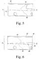
- FIG. 5is a perspective view of the washer assembly of FIG. 1 .
- FIG. 6is a perspective view of the washer assembly of FIG. 5 in a rotated position.
- FIG. 7is a cut-away view of a tensile rod assembly of the assembly tool of FIG. 1 .
- FIG. 7 ais a close-up view of a washer system and a pull rod according to one embodiment of the present invention.
- FIG. 8is a flow chart of the method for using the assembly tool according to one embodiment of the present invention.
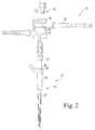
- FIG. 1is a perspective view of an assembly tool 10 according to one embodiment of the present invention.
- the assembly tool 10includes a first member 12 and a second member 14 . Coupled to the second member 14 is a washer system 16 .
- a drive mechanism 18is coupled to the washer system 16 .
- the first member 12has a first member longitudinal axis 20 and the second member 14 has a second member longitudinal axis 22 .
- the first member longitudinal axis 20 and the second member longitudinal axis 22are co-incident.
- the two axes 20 , 22may be parallel or offset at an angle from one another.
- the drive mechanism 18As the drive mechanism 18 is activated, it causes the washer system 16 to rotate about the second member longitudinal axis 22 .
- the drive mechanismis a handle that is ratcheted about the second member longitudinal axis 22 .
- itcould be a longitudinal handle, a Hudson connection that connects to a power source, or other known drive mechanism that would cause the washer system 16 to rotate about the second member longitudinal axis 22 .
- the modular implant 23includes a first component 24 (or a proximal or neck component) and a second component 26 (or a distal or stem component).
- the first member 12 of the assembly tool 10includes a distal end 28 that abuts a proximal end 30 of the neck component 24 .
- other connection meansmay be used.
- the distal end 28may include threads that engage a threaded end of the proximal end 30 of the neck component 24 .
- the connection meansmay be a retractable button/recess system, a slotted l-shaped recess and rod system, an undercut, an expandable collet system, or any other known engagement system.
- a distal end 32 of the second member 14engages a proximal end 34 of the stem component 26 .
- the distal end 32 of the second member 14is threaded and fits inside a threaded bore of the proximal end 34 of the stem component 26 .
- the distal end 32 of the second member 14may have the threaded bore and the proximal end 34 of the stem component may be threaded.
- other known means of connecting piecesmay be used.
- an expandable colletmay be used.
- the connection meansmay be a retractable button/recess system, an undercut, a slotted l-shaped recess and rod system, an expandable collet system, or any other known engagement system.
- the second member 14also includes a proximal end 36 ( FIG. 2 ).
- the proximal end 36includes a knob 68 ( FIG. 4 ).
- the knob 68is coupled to the threaded distal end 32 , such that as the knob 68 is rotated about the second member longitudinal axis 22 , the threaded distal end 32 is threaded into the threaded bore proximal end 34 of the stem component 26 .
- the washer system 16includes a first spiral washer 40 and a second spiral washer 42 .
- the first spiral washer 40is coupled to the drive mechanism 18 and includes a first spiral ramp 44 and the second spiral washer 42 is coupled to the second member 14 and the first spiral washer 40 and includes a second spiral ramp 46 ( FIG. 5 ).
- the first spiral ramp 44abuts the second spiral ramp 46 .
- the washer system 16has an overall starting height of h. As the first spiral ramp 44 is rotated relative to the second spiral ramp 46 , the ramps engage one another, creating a gap 48 between the first spiral washer 40 and the second spiral washer 42 .
- the gap 48is of a distance D. As shown in FIGS.
- the washers 40 , 42begin by being flush against one another. However, as the first spiral washer 40 is rotated, the spiral ramps 44 , 46 are rotated enlarging the height of the two washers 40 , 42 . The distance D of the gap 48 remains the same. In FIG. 6 , the overall height of the washer system 16 is now H, which is larger than h. This change in height is generated by the opposing spiral ramps 44 , 46 engaging one another, creating a washer system 16 with a variable height.
- the first washer 40includes a ratchet end 50 that opposes the spiral ramp 44 .
- the first washer 40is coupled to a ratchet washer 52 .
- the ratchet washer 52is connected to the handle 18 .
- One side 54 of the ratchet washer 52is ratcheted and mates with the ratchet end 50 of the first washer.
- the handle 18is turned, the ratchets on the ratchet washer 52 and first spiral washer 40 engage one another, causing the first spiral washer 40 to rotate.
- the second spiral washer 42is fixed, the two spiral ramps 44 , 46 engage and cause the first spiral washer 40 to become raised (by a height D) relative to the second spiral washer 42 .
- the second member 14includes a sacrificial member 56 , which in this case is a tensile rod or shear pin.
- the tensile rod 56includes an intentional weak spot or breakage point 58 .
- the breakage point 58can only tolerate up to a specific tension. After that load (or tension) is reached, the breakage point 58 breaks, leaving two separate pieces 60 , 62 .
- the tensile rod 56links an upper part 64 of the second member 14 to a lower part 66 of the second member 14 .
- tensionis created.
- the knob 68is turned to first thread the threaded end 32 of the second member 14 to the stem component 26 .
- the knob 68is coupled to the first spiral washer 40 in any number of known methods.
- the knob 68includes a pull rod 68 a having a shoulder 68 b .
- the shoulder 68 bis coupled to a counterbore 40 a in the first spiral washer 40 , such that as the first spiral washer 40 rotates and moves upwards along the longitudinal axis 22 , the knob 68 also moves upwards.
- a bearing 69is located between the shoulder 68 b and the counterbore 40 a .
- the bearing 69 illustratedis a rolling bearing and reduces the friction and torsional force felt by the pull rod 68 a (and thus the sacrificial member 56 ).
- the linear force at which the sacrificial member 56 will breakis kept more consistent.
- other types of bearingsmay be used.
- no bearing 69may be used and the shoulder 68 b abuts the counterbore 40 a directly.
- the knob 68also moves upwards. Because the knob 68 and threaded end 32 are coupled to one another and the threaded end is fixed within the stem component, the movement of the knob 68 creates tension along the second member 14 . Once the tension reaches a certain force (or load), the tensile rod 56 will break at the breakage point 58 . A loud noise will be heard; also the knob 68 will become loose. The tensile rod 56 breaking is important because it signals to the user that enough force has been applied. In this embodiment, the tensile rod 56 is fixed to break at a predetermined force.
- that forceis between about 2000 lbf and about 2500 lbf, and preferably at about 2250 lbf.
- the knob 68may also be used to disengage the ratchet washer 52 from the ratchet end 50 of the first washer 40 .
- the two halves 60 , 62 of the tensile rod 56are each fitted into slotted openings 70 , 72 , respectively, of the second member 14 .
- a sleeve 74fits around the tensile rod 56 .
- the first half 60 and the second half 62each include a rib 76 , 78 respectively, that extends outwardly.
- the ribs 76 , 78each fit within a recess 80 a , 80 b of the sleeve 74 .
- the ribs 76 , 78also engage an edge 82 , 84 of the recesses 80 a , 80 b .
- both the first and second halves 60 , 62remain contained within the sleeve 74 . Even though the first and second halves 60 , 62 are no longer connected directly to one another, rotation of one will cause the other to rotate.
- the knob 68is rotated, the slotted opening 70 rotates. This rotation causes the first half 60 of the tensile rod 56 to rotate.
- the first half 60rotates, it engages the edge 82 of the sleeve 74 , causing the sleeve 74 to rotate.
- the edge 84engages the second half 62 , causing the second half 62 to rotate.
- the second half 62 rotatingengages the slotted opening 72 , causing the lower portion 66 of the second member 14 to rotate, disengaging the threaded end 32 from the stem component 26 .
- the two halves 60 , 62 of the tensile rod 56are keyed together, such that even after the halves 60 , 62 break, they are still coupled together. Then, when one half rotates, the other half also is forced to rotate.
- the tensile rod 56is held by the second member. However, in other embodiments, it may be held by the first member. Also, any known containment method may be used. Alternatively, the tensile rod 56 need not be contained.
- the sacrificial member 56may not be a tensile rod, but could be a torsional member. Once loads are applied on a longitudinal axis, the torsional member feels rotational force (e.g., a torsional spring). The torsional spring could be weakened so as to break at a certain force. In other embodiments, the sacrificial member 56 could be designed to fail in both axial and torsional directions.
- the assembly tool 10may be made from stainless steel.
- the tensile rod 56are made from 440C stainless steel, while all other components are made from 17-4 stainless steel.
- the assembly tool 10may be made of plastic, with only the washer system 16 and the tensile rod 56 being made of stainless steel. In other embodiments, other metals may be used.
- the tensile rod 56could be made from plastic, ceramic, or other polymer.
- the sleeve 74could also be made of plastic or other polymer.
- the assembly tool 10may entirely be made of a single composite material.
- the tensile rod 56could be a small fixture with a shear pin.
- the distal end 28 of the first member 12could include dimples that would create impressions on the proximal end of the neck component 24 .
- the impressionswould serve as a direct correlation to the force applied to the modular construct, much like those produced by a Rockwell hardness test machine.
- the spherical dimples on 28could be positioned (clocked), such that, 3-impressions would be created in each use, regardless of the instrument-to-implant orientation.
- the physical size of the dimpleswould be predetermined, based on the material hardness of the proximal body. Other dimension (other than spherical) dimples could also be used. Alternatively, a number other than three dimples may be used.
- a biasing mechanismsuch as a wave spring or other type of spring, used to keep the ratchet washer 52 engaged with the ratchet end 50 of the first washer 40 .
- Other springsmay be used in the device to cause the first washer 40 to spring back after being ratcheted.
- the springmay be a constant force spring.
- FIG. 8a flow chart describing the method of using the assembly tool 10 is shown.
- the proximal componentis inserted on to the stem component.
- the distal end of the second memberis inserted into the opening of the stem component at step s 102 .
- the distal end of the first memberabuts the proximal end of the first component.
- the knobis rotated threading the distal end of the second member into the stem component.
- the drive mechanismis then turned, causing the knob to move upward (step s 106 ), as described above.
- step s 110the knob is rotated to disengage the threaded distal end from the stem component and the assembly tool is removed from the proximal and stem components (step s 112 ).
Landscapes
- Health & Medical Sciences (AREA)
- Transplantation (AREA)
- Orthopedic Medicine & Surgery (AREA)
- Heart & Thoracic Surgery (AREA)
- Cardiology (AREA)
- Oral & Maxillofacial Surgery (AREA)
- Engineering & Computer Science (AREA)
- Biomedical Technology (AREA)
- Physical Education & Sports Medicine (AREA)
- Vascular Medicine (AREA)
- Life Sciences & Earth Sciences (AREA)
- Animal Behavior & Ethology (AREA)
- General Health & Medical Sciences (AREA)
- Public Health (AREA)
- Veterinary Medicine (AREA)
- Prostheses (AREA)
Abstract
Description
Claims (12)
Priority Applications (5)
| Application Number | Priority Date | Filing Date | Title |
|---|---|---|---|
| US12/815,915US8533921B2 (en) | 2010-06-15 | 2010-06-15 | Spiral assembly tool |
| EP11169798AEP2397111B1 (en) | 2010-06-15 | 2011-06-14 | Orthopaedic prosthesis assembly tool |
| JP2011132097AJP5819109B2 (en) | 2010-06-15 | 2011-06-14 | Spiral assembly tool |
| US13/655,015US9101495B2 (en) | 2010-06-15 | 2012-10-18 | Spiral assembly tool |
| US14/788,865US10166118B2 (en) | 2010-06-15 | 2015-07-01 | Spiral assembly tool |
Applications Claiming Priority (1)
| Application Number | Priority Date | Filing Date | Title |
|---|---|---|---|
| US12/815,915US8533921B2 (en) | 2010-06-15 | 2010-06-15 | Spiral assembly tool |
Related Child Applications (1)
| Application Number | Title | Priority Date | Filing Date |
|---|---|---|---|
| US13/655,015Continuation-In-PartUS9101495B2 (en) | 2010-06-15 | 2012-10-18 | Spiral assembly tool |
Publications (2)
| Publication Number | Publication Date |
|---|---|
| US20110302760A1 US20110302760A1 (en) | 2011-12-15 |
| US8533921B2true US8533921B2 (en) | 2013-09-17 |
Family
ID=44303227
Family Applications (3)
| Application Number | Title | Priority Date | Filing Date |
|---|---|---|---|
| US12/815,915Active2030-11-24US8533921B2 (en) | 2010-06-15 | 2010-06-15 | Spiral assembly tool |
| US13/655,015Active2031-05-09US9101495B2 (en) | 2010-06-15 | 2012-10-18 | Spiral assembly tool |
| US14/788,865Active2031-03-28US10166118B2 (en) | 2010-06-15 | 2015-07-01 | Spiral assembly tool |
Family Applications After (2)
| Application Number | Title | Priority Date | Filing Date |
|---|---|---|---|
| US13/655,015Active2031-05-09US9101495B2 (en) | 2010-06-15 | 2012-10-18 | Spiral assembly tool |
| US14/788,865Active2031-03-28US10166118B2 (en) | 2010-06-15 | 2015-07-01 | Spiral assembly tool |
Country Status (3)
| Country | Link |
|---|---|
| US (3) | US8533921B2 (en) |
| EP (1) | EP2397111B1 (en) |
| JP (1) | JP5819109B2 (en) |
Cited By (4)
| Publication number | Priority date | Publication date | Assignee | Title |
|---|---|---|---|---|
| US9937048B2 (en) | 2015-01-15 | 2018-04-10 | Depuy Ireland Unlimited Company | Femoral stem including an anchor to facilitate assembly and implantation |
| US10022234B2 (en) | 2015-01-15 | 2018-07-17 | Depuy Ireland Unlimited Company | Assembly tool |
| US11207197B2 (en) | 2019-08-01 | 2021-12-28 | DePuy Synthes Products, Inc. | Orthopaedic surgical instrument for total hip arthroplasty and associated orthopaedic surgical method of use |
| US12414857B2 (en) | 2015-08-19 | 2025-09-16 | Depuy Ireland Unlimited Company | Alignment guide |
Families Citing this family (10)
| Publication number | Priority date | Publication date | Assignee | Title |
|---|---|---|---|---|
| US8556912B2 (en) | 2007-10-30 | 2013-10-15 | DePuy Synthes Products, LLC | Taper disengagement tool |
| US8518050B2 (en) | 2007-10-31 | 2013-08-27 | DePuy Synthes Products, LLC | Modular taper assembly device |
| US8533921B2 (en) | 2010-06-15 | 2013-09-17 | DePuy Synthes Products, LLC | Spiral assembly tool |
| US9095452B2 (en) | 2010-09-01 | 2015-08-04 | DePuy Synthes Products, Inc. | Disassembly tool |
| ES2635496T3 (en) | 2011-04-06 | 2017-10-04 | Depuy Synthes Products Llc | Modular Orthopedic Hip Prosthesis |
| EP2724693B1 (en)* | 2012-10-18 | 2016-04-13 | DePuy Synthes Products, LLC | Orthopaedic prosthesis assembly tool |
| GB201705917D0 (en) | 2017-04-12 | 2017-05-24 | Davidson Craig | Femoral trialling kit and assembly |
| DE102018100075A1 (en)* | 2018-01-03 | 2019-07-04 | Rz-Medizintechnik Gmbh | Surgical instrument |
| CA3175946A1 (en) | 2020-05-21 | 2021-11-25 | Good News Medical Co., Ltd. | Device for alleviating obstructive sleep apnea |
| US12127955B2 (en) | 2021-04-29 | 2024-10-29 | Depuy Ireland Unlimited Company | Trial component and method |
Citations (52)
| Publication number | Priority date | Publication date | Assignee | Title |
|---|---|---|---|---|
| US3810312A (en) | 1971-11-11 | 1974-05-14 | Const Supply Co | Alignment instrument |
| US3889558A (en) | 1974-02-19 | 1975-06-17 | Gorden E Duncan | Shock absorber nut removing tool |
| US4305394A (en) | 1980-12-22 | 1981-12-15 | Bertuch Jr Charles J | Acetabular cup positioning instrument |
| US4601289A (en) | 1985-04-02 | 1986-07-22 | Dow Corning Wright | Femoral trial prosthesis/rasp assembly |
| US4959066A (en) | 1989-02-24 | 1990-09-25 | Zimmer, Inc. | Femoral osteotomy guide assembly |
| US5002581A (en) | 1989-11-03 | 1991-03-26 | Dow Corning Wright Corporation | Modular hip joint prosthesis with adjustable anteversion |
| US5002578A (en) | 1990-05-04 | 1991-03-26 | Venus Corporation | Modular hip stem prosthesis apparatus and method |
| US5057112A (en) | 1990-01-04 | 1991-10-15 | Intermedics Orthopedics, Inc. | Pneumatically powered orthopedic broach |
| US5190550A (en) | 1990-08-02 | 1993-03-02 | Exactech, Inc. | Locking surgical tool handle system |
| US5342363A (en) | 1992-11-30 | 1994-08-30 | Wright Medical Technology, Inc. | Medical instrument and procedure |
| US5352231A (en) | 1992-11-23 | 1994-10-04 | Danek Medical, Inc. | Nut starter wrench for orthopedic fixation system |
| US5409492A (en) | 1993-08-09 | 1995-04-25 | Stelkast Incorporated | System for coupling an implant to a tool for inserting and removing the implant |
| US5540687A (en) | 1993-05-19 | 1996-07-30 | Fairley; Jeffrey D. | Device for the distraction of bones |
| US5653765A (en) | 1994-07-01 | 1997-08-05 | Ortho Development Corporation | Modular prosthesis |
| US5858020A (en) | 1995-12-05 | 1999-01-12 | Metagen, Llc | Modular prosthesis |
| US5876459A (en) | 1996-08-30 | 1999-03-02 | Powell; Douglas Hunter | Adjustable modular orthopedic implant |
| US5938701A (en) | 1996-11-15 | 1999-08-17 | Hiernard; Bruno | Extraction device |
| EP1000595A1 (en) | 1998-11-11 | 2000-05-17 | Società per Azioni SAMO | Extractor for removing the bioceramic insert from the acetabular cup of a hip prosthesis |
| US6080162A (en) | 1998-09-28 | 2000-06-27 | Depuy Orthopaedics, Inc. | Modular orthopaedic clamping tool |
| US6110179A (en) | 1998-03-02 | 2000-08-29 | Benoist Girard Sas | Prosthesis inserter |
| US6165177A (en) | 1998-12-24 | 2000-12-26 | Depuy Orthopaedics, Inc. | Alignment guide for insertion of stem prosthesis |
| US6193759B1 (en) | 1997-03-26 | 2001-02-27 | Depuy Orthopaedics, Inc. | Modular long stem hip trial |
| US6238435B1 (en) | 2000-03-10 | 2001-05-29 | Bristol-Myers Squibb Co | Assembly tool for prosthetic implant |
| DE20114835U1 (en) | 2001-09-03 | 2001-12-06 | Merete Medical GmbH, 12247 Berlin | Adapter and puller for hip joints |
| US6330845B1 (en) | 2000-05-17 | 2001-12-18 | Bristol-Myers Squibb | Wrench for an implant |
| US6361563B2 (en) | 1999-09-01 | 2002-03-26 | Wright Medical Technology, Inc. | Radial head implant system including modular implant and modular radial head locking instrument |
| US6491696B1 (en) | 1998-05-20 | 2002-12-10 | Medicon Chirurgiemechaniker-Genossenschaft | Device for distracting bone segments, especially in the area of a jaw |
| US20030149487A1 (en) | 2002-02-04 | 2003-08-07 | Doubler Robert L. | Skeletal fixation device with linear connection |
| US6706072B2 (en) | 2000-11-08 | 2004-03-16 | Depuy Orthopaedics, Inc. | Modular prosthesis having a stem component with a counterbored cavity defined therein and associated method |
| US20040054373A1 (en) | 2002-05-09 | 2004-03-18 | Serra Michael A. | Modular implant assembly tool |
| US20040073315A1 (en) | 2002-04-25 | 2004-04-15 | Justin Daniel F. | Modular bone implant, tools, and method |
| US6743235B2 (en) | 2002-10-15 | 2004-06-01 | Goli V. Subba Rao | Modular instrument for positioning acetabular prosthetic socket |
| US20040122440A1 (en) | 2002-12-20 | 2004-06-24 | Daniels David W. | Instrument and associated method of trialing for modular hip stems |
| US20040122439A1 (en) | 2002-12-20 | 2004-06-24 | Dwyer Kimberly A. | Adjustable biomechanical templating & resection instrument and associated method |
| US20040122437A1 (en) | 2002-12-20 | 2004-06-24 | Dwyer Kimberly A. | Alignment device for modular implants and method |
| US20040122525A1 (en) | 2002-12-20 | 2004-06-24 | Daniels David W. | Modular hip stems and associated method of trialing |
| US20040267267A1 (en) | 2003-06-25 | 2004-12-30 | Daniels David Wayne | Non-linear reamer for bone preparation and associated method |
| US20040267373A1 (en) | 2003-06-25 | 2004-12-30 | Dwyer Kimberly Ann | Assembly tool for modular implants and associated method |
| US20050033444A1 (en) | 2003-06-25 | 2005-02-10 | Jones Michael C. | Assembly tool for modular implants and associated method |
| US6883217B2 (en) | 2002-12-13 | 2005-04-26 | Zimmer Technology, Inc. | Apparatus for disassembling mating taper connections |
| US6905515B1 (en) | 2003-12-27 | 2005-06-14 | Zimmer Technology, Inc. | Junction for a modular implant |
| US7066042B2 (en)* | 2004-01-07 | 2006-06-27 | Sanford L.P. | Advancing/retracting mechanism |
| US20060217737A1 (en) | 2003-03-24 | 2006-09-28 | Orthometer A/S | System, method and tool for ensuring correct insertion of an artificial hip joint |
| US20060260440A1 (en) | 2005-05-23 | 2006-11-23 | Custom Spine, Inc. | Ratcheting torque wrench |
| US20070005144A1 (en) | 2005-06-30 | 2007-01-04 | Leisinger Steven R | Expandable acetabular liner extraction device, cup assembly and associated method |
| US7188556B1 (en)* | 2004-10-12 | 2007-03-13 | Pilling Weck Incorporated | Rotatable hand tool with a torque controller and method |
| US20070123908A1 (en) | 2003-06-25 | 2007-05-31 | Depuy Products, Inc. | Assembly tool for modular implants, kit and associated method |
| WO2007098549A1 (en) | 2006-03-03 | 2007-09-07 | Portland Orthopaedics Limited | Multi function hammer |
| US20090112216A1 (en) | 2007-10-30 | 2009-04-30 | Leisinger Steven R | Taper disengagement tool |
| US20090112218A1 (en) | 2007-10-31 | 2009-04-30 | Mccleary Larry G | Modular taper assembly device |
| FR2926212A1 (en) | 2008-01-16 | 2009-07-17 | Evolutis Sa | Prosthetic articulation implant for bones, has hemispherical head with arrangements cooperating with extraction unit for extracting head with respect to collar from polar zone of head, where extraction unit is constituted by return spring |
| US7585329B2 (en) | 2006-11-28 | 2009-09-08 | Depuy Products, Inc. | Modular proximal body trial |
Family Cites Families (502)
| Publication number | Priority date | Publication date | Assignee | Title |
|---|---|---|---|---|
| US422013A (en) | 1890-02-25 | Cannon-wheel remover | ||
| US650795A (en) | 1900-01-17 | 1900-05-29 | William T Maxwell | Boring implement. |
| US742521A (en) | 1901-12-12 | 1903-10-27 | John W Terry | Spring-bed. |
| US784243A (en) | 1904-05-28 | 1905-03-07 | Haywood S Winkler | Wrench. |
| US1029402A (en) | 1911-04-11 | 1912-06-11 | Richard H Ritter | Milling attachment for drill-presses. |
| US1241846A (en) | 1916-06-21 | 1917-10-02 | Edward H Grons | Cam-shaft-bearing remover. |
| US1383304A (en) | 1920-04-27 | 1921-07-05 | Thomas B Hughes | Feeding mechanism for plates and the like |
| US1423649A (en) | 1920-06-26 | 1922-07-25 | Sylvester Brown Shepherd | Fertilizer distributer |
| US1661682A (en) | 1922-03-08 | 1928-03-06 | Fisk Rubber Co | Wrench mechanism |
| US1534692A (en) | 1924-06-14 | 1925-04-21 | Davis William Daniel | Hydro-auto-helicopter |
| US1551557A (en) | 1925-07-17 | 1925-09-01 | Henry gtjttin | |
| US2234824A (en) | 1939-02-06 | 1941-03-11 | Robert P Kingston | Bushing puller |
| US2248054A (en) | 1939-06-07 | 1941-07-08 | Becker Joseph | Screw driver |
| US2487331A (en) | 1947-12-05 | 1949-11-08 | Paragon Products Corp | Bushing remover |
| US2631584A (en) | 1948-07-22 | 1953-03-17 | Alfred T Purificato | Fracture securing instrument |
| US2626023A (en) | 1948-12-24 | 1953-01-20 | Chicago Pneumatic Tool Co | Drill post |
| US2661033A (en) | 1952-03-05 | 1953-12-01 | United Engineering Company | Roll shifting means for resaw devices |
| US2711196A (en) | 1953-06-01 | 1955-06-21 | David M Daniel | Tilting arbor band saw |
| US2902596A (en) | 1953-06-11 | 1959-09-01 | Bendix Aviat Corp | Transceiver for multi-channel radio communication systems |
| US2834382A (en) | 1953-07-13 | 1958-05-13 | Ernest Roe | Gripper for wire tying machine |
| US2834099A (en) | 1953-10-08 | 1958-05-13 | Western Electric Co | Apparatus for inserting and removing pins |
| US3101875A (en) | 1954-06-04 | 1963-08-27 | Michel David Daniel | Valve and dispensing apparatus for pressure containers and the like |
| US2864282A (en) | 1954-11-08 | 1958-12-16 | Nat Broach & Mach | Method of crown finishing the teeth of internal gears |
| US2895154A (en) | 1955-02-09 | 1959-07-21 | Belcher David Daniel | Paint roller cleaner |
| NL113890C (en) | 1955-07-27 | |||
| US2856637A (en) | 1956-04-30 | 1958-10-21 | Nat Broach & Mach | Method of making a gear finishing tool |
| US2914224A (en) | 1956-08-09 | 1959-11-24 | Michel David Daniel | Valve assembly for pressure containers and the like |
| US3059278A (en) | 1957-08-12 | 1962-10-23 | Nat Broach & Mach | Apparatus for making hones |
| US2977726A (en) | 1957-04-22 | 1961-04-04 | Nat Broach & Mach | Gear honing tool |
| US2994461A (en) | 1957-07-02 | 1961-08-01 | Michel David Daniel | Dispensing apparatus |
| US2944373A (en) | 1958-03-03 | 1960-07-12 | Nat Broach & Mach | Grinder with compensating trimming mechanism |
| US2974699A (en) | 1958-03-05 | 1961-03-14 | Basic Vegets Le Products Inc | Onion topper and slicer |
| US2957610A (en) | 1958-03-21 | 1960-10-25 | Michel David Daniel | Dispensing apparatus |
| US2975944A (en) | 1958-06-04 | 1961-03-21 | Michel David Daniel | Foam valve assembly |
| US3071862A (en) | 1958-06-23 | 1963-01-08 | Nat Broach & Mach | Involute checker |
| US2994988A (en) | 1958-07-07 | 1961-08-08 | Nat Broach & Mach | Gear grinder guiding and incremental feeding means |
| US2981035A (en) | 1958-11-24 | 1961-04-25 | Nat Broach & Mach | Grinder |
| US3048307A (en) | 1959-08-24 | 1962-08-07 | Michel David Daniel | Device for dispensing aerated products |
| US3077877A (en) | 1959-12-21 | 1963-02-19 | Nat Broach & Mach | Hone dressing apparatus |
| US3092934A (en) | 1960-07-01 | 1963-06-11 | Nat Broach & Mach | Method and apparatus for finishing gears |
| US3092935A (en) | 1960-09-06 | 1963-06-11 | Nat Broach & Mach | Method and apparatus for finishing gears |
| US3135136A (en) | 1960-10-03 | 1964-06-02 | Nat Broach & Mach | Indexing mechanism |
| US3250745A (en) | 1961-08-04 | 1966-05-10 | Nopco Chem Co | Alkylated bisphenol alkylene oxide adduct based polyurethane prepolymers |
| US3200484A (en) | 1962-04-16 | 1965-08-17 | Robert C Garman | Axle puller |
| US3177507A (en) | 1962-05-24 | 1965-04-13 | Buell Ind Inc | Bolt pointer |
| US3180532A (en) | 1964-06-18 | 1965-04-27 | Clayton Corp Of Delaware | Tamper-proof cover for a container |
| US3300833A (en) | 1965-01-11 | 1967-01-31 | Nat Broach & Mach | Serrated gear shaving tool |
| US3220311A (en) | 1965-01-11 | 1965-11-30 | Nat Broach & Mach | Relief shaving |
| US3301134A (en) | 1965-03-24 | 1967-01-31 | Nat Broach & Mach | Incremental hob shift mechanism |
| US3293987A (en) | 1965-06-01 | 1966-12-27 | Nat Broach & Mach | Method of gear shaving |
| US3331115A (en) | 1965-09-13 | 1967-07-18 | Nat Broach & Mach | Pot broach |
| US3319526A (en) | 1965-10-14 | 1967-05-16 | Nat Broach & Mach | Gear shaving machine |
| US3424783A (en) | 1966-05-06 | 1969-01-28 | Grace W R & Co | Aminonitrile synthesis |
| US3451111A (en) | 1966-08-08 | 1969-06-24 | Lear Siegler Inc | Gear shaving cutter and the method of using the same |
| US3335639A (en) | 1966-11-14 | 1967-08-15 | Nat Broach & Mach | Method and apparatus for producing a shaving cutter |
| US3443478A (en) | 1967-02-08 | 1969-05-13 | Lear Siegler Inc | Gear shaving machine |
| US3479387A (en) | 1967-09-26 | 1969-11-18 | Grace W R & Co | Process for preparing n-methylglycinonitrile |
| US3499920A (en) | 1967-12-21 | 1970-03-10 | Grace W R & Co | Process for preparing n-methylglycinonitrile |
| US3479388A (en) | 1967-12-26 | 1969-11-18 | Grace W R & Co | Process for preparing n-methylglycinonitrile |
| US3483175A (en) | 1968-01-05 | 1969-12-09 | Grace W R & Co | Polymers containing beta-haloisocyanate groups |
| US3494752A (en) | 1968-03-04 | 1970-02-10 | Lear Siegler Inc | Method of manufacturing metal bonded abrasive gear hones |
| US3541868A (en) | 1968-04-08 | 1970-11-24 | Robert M Hall | Surgical impactor-extractor appliance |
| US3679728A (en) | 1968-08-13 | 1972-07-25 | Grace W R & Co | Process for preparing methylenebisiminodiacetonitrile |
| US3679729A (en) | 1968-08-13 | 1972-07-25 | Grace W R & Co | Continuous process for preparing methylenebisiminodiacetonitrile |
| US3580027A (en) | 1968-12-02 | 1971-05-25 | Lear Siegler Inc | Gear rolling |
| US3580029A (en) | 1968-12-05 | 1971-05-25 | Lear Siegler Inc | Rolling chamfers on gear teeth |
| US3668139A (en) | 1968-12-10 | 1972-06-06 | Grace W R & Co | Catalyst and method of polyester polymerization |
| US3633583A (en) | 1969-08-22 | 1972-01-11 | Meyer Fishbein | Orthopedic single-blade bone cutter |
| US3629981A (en) | 1969-10-06 | 1971-12-28 | Joseph S Mccaffery | Adjustable height structure cover for manholes and the like |
| US3631703A (en) | 1969-10-15 | 1972-01-04 | Lear Siegler Inc | Gear rolling die and method of use |
| US3604235A (en) | 1969-10-30 | 1971-09-14 | Lear Siegler Inc | Rolling of tapered gears |
| US3673887A (en) | 1970-09-23 | 1972-07-04 | Lear Siegler Inc | Indexable adjustable abutment |
| US3691718A (en) | 1970-09-28 | 1972-09-19 | Gen Foods Corp | Pouch forming apparatus and method |
| US3705513A (en) | 1970-11-19 | 1972-12-12 | Lear Siegler Inc | Rolling high helix pinions |
| US3700957A (en) | 1971-01-13 | 1972-10-24 | Grace W R & Co | Flame retardant polyester plasticizer containing 2,2-dibromomethylene-1,3-propanediol |
| US3754586A (en) | 1971-05-10 | 1973-08-28 | D Daniels | Process and apparatus for making shakes |
| US3869394A (en) | 1971-06-11 | 1975-03-04 | Grace W R & Co | Lubricant composition and method |
| US3749365A (en) | 1972-01-26 | 1973-07-31 | Brammell Inc | Primary opening apparatus |
| US3862483A (en) | 1972-10-10 | 1975-01-28 | Kenneth D Kloster | Special arbor press tool |
| US3912727A (en) | 1972-11-22 | 1975-10-14 | Grace W R & Co | Preparation of phenothiazines |
| US3849322A (en) | 1973-05-22 | 1974-11-19 | Grace W R & Co | Alkylated tertiary amines as high-temperature antioxidants for ester base lubricants |
| DE2340546A1 (en) | 1973-08-10 | 1975-02-27 | Pfaudler Werke Ag | METALLIC IMPLANT AND PROCEDURE FOR ITS MANUFACTURING |
| CH593674A5 (en) | 1974-09-11 | 1977-12-15 | Friedrichsfeld Gmbh | |
| US4051559A (en) | 1974-12-27 | 1977-10-04 | Mahay & Cie | Total prosthesis of the hip |
| US4009712A (en) | 1975-08-07 | 1977-03-01 | The Sampson Corporation | Fluted hip nail implant system for orthopaedic surgery |
| DE2543723C3 (en) | 1975-10-01 | 1978-04-06 | Aesculap-Werke Ag Vormals Jetter & Scheerer, 7200 Tuttlingen | Milling tool for surgical purposes |
| USD246507S (en) | 1976-03-01 | 1977-11-29 | International Business Machines Corporation | Container for liquids |
| FR2349319A2 (en) | 1976-04-26 | 1977-11-25 | Rambert Andre | HIP PROSTHESIS |
| US4035988A (en) | 1976-06-04 | 1977-07-19 | General Foods Corporation | Vacuum pocket-opening turret |
| GB1601576A (en) | 1977-06-01 | 1981-10-28 | Howmedica | Elbow prosthesis |
| US4150909A (en) | 1978-01-09 | 1979-04-24 | Daniel David W | Breakwater system |
| USD258957S (en) | 1978-05-22 | 1981-04-21 | Discovision Associates | Keyboard housing |
| USD257533S (en) | 1978-05-22 | 1980-11-18 | Discovision Associates | Video disk player |
| US4686978A (en) | 1978-08-07 | 1987-08-18 | Wadsworth Thomas G | Instrumentation for implantation of an elbow prosthesis |
| US4420864A (en) | 1979-12-12 | 1983-12-20 | Omco, Inc. | Bolt type lock puller |
| USD267151S (en) | 1980-05-01 | 1982-12-07 | International Business Machines Corporation | Typewriter |
| DE3023942C2 (en) | 1980-06-26 | 1985-05-15 | Waldemar Link (Gmbh & Co), 2000 Hamburg | Implant for insertion between the vertebral body of the spine and forceps for insertion and distraction of the same |
| USD266768S (en) | 1980-12-23 | 1982-11-02 | International Business Machines Corporation | Typewriter |
| US4398074A (en) | 1981-06-12 | 1983-08-09 | Oak Industries Inc. | Low profile switch having a sealed interior |
| US4457306A (en) | 1982-05-05 | 1984-07-03 | Howmedica, Inc. | Tool and method for engaging two members of a joint prosthesis |
| USD275006S (en) | 1983-01-05 | 1984-08-07 | AT&T Bell Telephone Laboratories | Telephone handset |
| US4473070A (en) | 1983-01-05 | 1984-09-25 | Regents Of The University Of Michigan | Intramedullary reamer |
| AU89064S (en) | 1983-01-21 | 1984-06-14 | British Gas Corp | Transmitter unit |
| AU89063S (en) | 1983-01-21 | 1984-06-14 | British Gas Corp | Detector receiver unit |
| US4538886A (en) | 1983-04-19 | 1985-09-03 | Stellar Energy Ststems, Inc. | Circular arc solar concentrator |
| US4458420A (en)* | 1983-07-20 | 1984-07-10 | Davis Kurtis D | Shear pin hilt for knife |
| US4608055A (en) | 1984-01-12 | 1986-08-26 | Mayo Foundation | Femoral component for hip prosthesis |
| USD285073S (en) | 1984-04-09 | 1986-08-12 | At&T Bell Laboratories | Telephone handset |
| USD285198S (en) | 1984-04-09 | 1986-08-19 | At&T Technologies, Inc. | Telephone base |
| GB8409714D0 (en) | 1984-04-13 | 1984-05-23 | Finsbury Instr Ltd | Hip implant |
| DE3417609A1 (en) | 1984-05-11 | 1985-11-14 | Waldemar Link (Gmbh & Co), 2000 Hamburg | ARRANGEMENT FOR PRODUCING ANATOMICALLY APPROPRIATE ENDOPROTHESIS |
| US4686971A (en) | 1984-11-19 | 1987-08-18 | Harris William H | Method and apparatus for extraction of prostheses |
| FR2576777B1 (en) | 1985-01-31 | 1987-03-06 | Rhenter Jean Luc | TOTAL HIP PROSTHESIS WITH PRIMARY FIXING |
| USD290399S (en) | 1985-03-04 | 1987-06-16 | Zimmer, Inc. | Combined driver and extractor for intramedullary pins or the like |
| GB8516167D0 (en) | 1985-06-26 | 1985-07-31 | Finsbury Instr Ltd | Surgical tool |
| USD286198S (en) | 1985-08-02 | 1986-10-14 | Bancroft Joseph C | Vent latch jamb |
| US4710946A (en) | 1985-08-06 | 1987-12-01 | Amoco Corporation | Method and apparatus for X-ray video fluoroscopic analysis of rock samples |
| DE3538654A1 (en) | 1985-10-28 | 1987-04-30 | Mecron Med Prod Gmbh | DRILLING SYSTEM CONTAINING A DRILL GUIDE FOR THE INSERTION OF AN ENDOPROTHESIS AND RELATED PROSTHESIS |
| USD287494S (en) | 1986-01-06 | 1986-12-30 | At&T Information Systems | Telephone stand |
| USD286285S (en) | 1986-01-06 | 1986-10-21 | At&T Information Systems Inc. | Telephone stand |
| EP0239711B1 (en) | 1986-04-02 | 1989-05-24 | Franz Plasser Bahnbaumaschinen-Industriegesellschaft m.b.H. | Mobile plant cleaning the ballast of a track with means to distribute said ballast |
| USD289155S (en) | 1986-05-30 | 1987-04-07 | At&T Information Systems | Telephone answering device |
| EP0257359B1 (en) | 1986-08-15 | 1991-11-27 | Boehringer Mannheim Corporation | Modular hip prosthesis |
| US5080685A (en) | 1986-08-15 | 1992-01-14 | Boehringer Mannheim Corporation | Modular hip prosthesis |
| US4716894A (en) | 1986-08-27 | 1988-01-05 | Zimmer, Inc. | Acetabular cup inserting instrument |
| CH670198A5 (en) | 1986-10-02 | 1989-05-31 | Sulzer Ag | |
| FR2606628B1 (en) | 1986-11-13 | 1995-07-21 | Bataille Jacques | MULTI-PIECE HIP JOINT PROSTHESES |
| JPH0547184Y2 (en) | 1987-03-04 | 1993-12-10 | ||
| US5197989A (en) | 1987-09-03 | 1993-03-30 | Hinckfuss Bruce W | Two stage joint prosthesis |
| USD313233S (en) | 1987-11-02 | 1990-12-25 | At&T Bell Laboratories | Telephone answering set |
| FR2626212B1 (en) | 1988-01-22 | 1990-06-15 | Canadair Inc | METHOD AND DEVICE FOR MOLDING AND COOKING COMPOSITE MATERIAL FOR FORMING A REINFORCED COATING PANEL |
| DE3809793A1 (en) | 1988-03-23 | 1989-10-05 | Link Waldemar Gmbh Co | SURGICAL INSTRUMENT SET |
| USD303114S (en) | 1988-03-28 | 1989-08-29 | American Telephone And Telegraph Company, At&T Information Systems | Telephone set |
| US4923422A (en) | 1988-04-06 | 1990-05-08 | Zenith Electronics Corporation | Process for an improved tension mask support structure |
| US4891545A (en) | 1988-04-06 | 1990-01-02 | Zenith Electronics Corporation | Faceplate front assembly with improved tension mask support structure |
| USD304587S (en) | 1988-09-21 | 1989-11-14 | American Telephone And Telegraph Company | Telephone dialer adjunct |
| US4938773A (en) | 1989-01-18 | 1990-07-03 | Strand John A | Hip joint prosthesis |
| US5016858A (en) | 1989-01-24 | 1991-05-21 | Mitchell William D | Hydraulic lift mechanism for camper shells |
| US5047033A (en) | 1989-02-08 | 1991-09-10 | Smith & Nephew Richards Inc. | Mill and guide apparatus for preparation of a hip prosthesis |
| USRE38058E1 (en) | 1989-02-08 | 2003-04-01 | Smith & Nephew, Inc. | Mill and guide apparatus for preparation of a hip prosthesis |
| US5108452A (en) | 1989-02-08 | 1992-04-28 | Smith & Nephew Richards Inc. | Modular hip prosthesis |
| US4969911A (en) | 1989-02-17 | 1990-11-13 | United States Manufacturing Company | Adjustable prosthetic joint with alignment means |
| US5061271A (en) | 1989-02-27 | 1991-10-29 | Boehringer Mannheim Corporation | Tool for separating components of a modular joint prosthesis |
| US4997621A (en) | 1989-03-13 | 1991-03-05 | General Electric Company | Lower tie plate with stepped holes to control pressure drop and flow distribution |
| US5062845A (en) | 1989-05-10 | 1991-11-05 | Spine-Tech, Inc. | Method of making an intervertebral reamer |
| USD315343S (en) | 1989-08-11 | 1991-03-12 | At&T Bell Laboratories | Facsimile transceiver |
| US4917530A (en) | 1989-08-31 | 1990-04-17 | Boehringer Mannheim Corporation | Structural joint |
| US5060505A (en) | 1989-09-12 | 1991-10-29 | Sensors, Inc. | Non-dispersive infrared gas analyzer system |
| US5184017A (en) | 1989-09-12 | 1993-02-02 | Sensors, Inc. | Method and apparatus for detecting a component gas in a sample |
| US5135529A (en) | 1989-11-03 | 1992-08-04 | Dow Corning Wright Corporation | Instrument for implanting modular hip joint prosthesis with adjustable anteversion and method of using said instrument |
| US5201882A (en) | 1989-11-03 | 1993-04-13 | Paxson Robert D | Modular hip joint prosthesis with adjustable anteversion |
| US5171244A (en) | 1990-01-08 | 1992-12-15 | Caspari Richard B | Methods and apparatus for arthroscopic prosthetic knee replacement |
| USD319439S (en) | 1990-04-19 | 1991-08-27 | At&T Bell Laboratories | Adjunct answering machine |
| USD320985S (en) | 1990-04-19 | 1991-10-22 | At&T Bell Laboratories | Integrated answering machine |
| USD318051S (en) | 1990-04-23 | 1991-07-09 | At&T Bell Laboratories | Telephone stand |
| CA2084095C (en) | 1990-06-01 | 2002-04-02 | David Clark Kelman | Metal/composite hybrid orthopedic implants |
| US5033180A (en) | 1990-07-25 | 1991-07-23 | Colson Fred T | Bearing puller |
| US5047035A (en) | 1990-08-10 | 1991-09-10 | Mikhail Michael W E | System for performing hip prosthesis revision surgery |
| US5100407A (en) | 1990-09-04 | 1992-03-31 | Pfizer Hospital Products Group, Inc. | Modular trial hip replacement system |
| USD337639S (en) | 1990-11-21 | 1993-07-20 | Zimmer, Inc. | Combined impactor and extractor for prosthetic implants |
| GB9026592D0 (en) | 1990-12-06 | 1991-01-23 | Meswania Jayantilal M | Surgical instrument |
| US5020519A (en) | 1990-12-07 | 1991-06-04 | Zimmer, Inc. | Sagittal approximator |
| US5049150A (en) | 1990-12-27 | 1991-09-17 | Zimmer, Inc. | Tool for gripping a bone fragment |
| US5217462A (en) | 1991-03-05 | 1993-06-08 | Pfizer Hospital Products Group, Inc. | Screw and driver |
| US5053037A (en) | 1991-03-07 | 1991-10-01 | Smith & Nephew Richards Inc. | Femoral instrumentation for long stem surgery |
| USD323657S (en) | 1991-04-08 | 1992-02-04 | At&T Bell Laboratories | Telephone station having a touch-screen display |
| US5190548A (en) | 1991-04-10 | 1993-03-02 | Linvatec Corporation | Surgical reamer |
| US5218814A (en) | 1991-06-14 | 1993-06-15 | Deere & Company | Engine and transaxle module |
| USD340461S (en) | 1991-06-14 | 1993-10-19 | Deere & Company | Vehicle body |
| US5099714A (en) | 1991-06-14 | 1992-03-31 | Deere & Company | Rack and pinion steering mechanism |
| US5162626A (en) | 1991-06-14 | 1992-11-10 | Deere & Company | Seat switch mud flap activator integrally mounted to the seat |
| US5171055A (en) | 1991-06-14 | 1992-12-15 | Deere & Company | Vehicle seat mechanism |
| US5133588A (en) | 1991-06-14 | 1992-07-28 | Deere & Company | Seat assembly with integral fuel tank |
| USD338473S (en) | 1991-06-14 | 1993-08-17 | Deere & Company | Vehicle structure |
| US5238267A (en) | 1991-06-14 | 1993-08-24 | Deere & Company | Vehicle structure |
| US5258098A (en) | 1991-06-17 | 1993-11-02 | Cycam, Inc. | Method of production of a surface adapted to promote adhesion |
| SE9102216D0 (en) | 1991-07-23 | 1991-07-23 | Astra Ab | HIP JOINT PROSTHESIS |
| US5658349A (en) | 1991-07-29 | 1997-08-19 | Joint Medical Products Corporation | Prosthetic joint system for bone replacement |
| US5457100A (en) | 1991-12-02 | 1995-10-10 | Daniel; David G. | Method for treatment of recurrent paroxysmal neuropsychiatric |
| US5169401A (en) | 1991-12-20 | 1992-12-08 | Zimmer, Inc. | Surgical reamer assembly |
| US5344423A (en) | 1992-02-06 | 1994-09-06 | Zimmer, Inc. | Apparatus and method for milling bone |
| US5507833A (en) | 1992-02-10 | 1996-04-16 | Kim-Med, Inc. | Hip replacement system and method for implanting the same |
| US5342366A (en) | 1992-02-19 | 1994-08-30 | Biomet, Inc. | Surgical instruments for hip revision |
| EP0558203A1 (en) | 1992-02-20 | 1993-09-01 | Wright Medical Technology, Inc. | Modular trial instrument with interlock mechanism |
| US5422478A (en) | 1992-04-17 | 1995-06-06 | Fiberoptic Sensor Technologies, Inc. | Fiberoptic pressure sensor having drift correction means for insitu calibration |
| US5247171A (en) | 1992-04-17 | 1993-09-21 | Fiberoptic Sensor Technologies, Inc. | Drift correction for fiberoptic pressure sensors |
| US5207680A (en) | 1992-05-11 | 1993-05-04 | Zimmer, Inc. | Front milling guide for use in orthopaedic surgery |
| US5331124A (en) | 1992-07-20 | 1994-07-19 | Methode Electronics, Inc. | Wireless floating horn switch |
| US5372209A (en) | 1992-07-28 | 1994-12-13 | Dcd, Ltd. | Polycentric reamer |
| US5336226A (en) | 1992-08-11 | 1994-08-09 | Chapman Lake Instruments, Inc. | Bone face cutter |
| CH685533A5 (en) | 1992-10-13 | 1995-08-15 | Philipp Rolf Kropf Albert Geis | Modular hip prosthesis stem. |
| US5951606A (en) | 1992-11-20 | 1999-09-14 | Burke; Dennis W. | Centering device for femoral implant and method and apparatus for implementation thereof |
| DE69331586T2 (en) | 1992-11-20 | 2002-10-24 | Dennis W. Burke | IMPROVED FEMORAL CUFF IMPLANT |
| US5290313A (en) | 1992-11-23 | 1994-03-01 | Zimmer, Inc. | Offset prosthetic stem extension |
| FR2699400B1 (en) | 1992-12-18 | 1995-02-24 | Medinov Sa | Humeral stem for shoulder prosthesis. |
| US5403320A (en) | 1993-01-07 | 1995-04-04 | Venus Corporation | Bone milling guide apparatus and method |
| USD346979S (en) | 1993-02-11 | 1994-05-17 | Zimmer, Inc. | Bone milling template |
| US5507824A (en) | 1993-02-23 | 1996-04-16 | Lennox; Dennis W. | Adjustable prosthetic socket component, for articulating anatomical joints |
| USD353394S (en) | 1993-03-02 | 1994-12-13 | M&R Marking Systems, Inc. | Dater hand stamp |
| USD355187S (en) | 1993-03-04 | 1995-02-07 | At&T Corp. | Telephone answering machine |
| USD355186S (en) | 1993-03-04 | 1995-02-07 | At&T Corp. | Telephone answering machine |
| USD352521S (en) | 1993-03-10 | 1994-11-15 | M&R Marking Systems, Inc. | Pre-inked mount |
| USD357315S (en) | 1993-03-15 | 1995-04-11 | Zimmer, Inc. | Bone milling template |
| US5908423A (en) | 1993-05-27 | 1999-06-01 | Howmedica, Inc. | Flexible medullary reaming system |
| US5540694A (en) | 1993-06-01 | 1996-07-30 | Joint Medical Products Corporation | Instrument for cutting bone |
| GB2279017B (en) | 1993-06-18 | 1996-09-18 | Paul Costain | Quick coupling cue stick |
| US5420910B1 (en) | 1993-06-29 | 1998-02-17 | Airtouch Communications Inc | Method and apparatus for fraud control in cellular telephone systems utilizing rf signature comparison |
| US5950121A (en) | 1993-06-29 | 1999-09-07 | Airtouch Communications, Inc. | Method and apparatus for fraud control in cellular telephone systems |
| US5474559A (en) | 1993-07-06 | 1995-12-12 | Zimmer, Inc. | Femoral milling instrumentation for use in total knee arthroplasty with optional cutting guide attachment |
| CA2126627C (en) | 1993-07-06 | 2005-01-25 | Kim C. Bertin | Femoral milling instrumentation for use in total knee arthroplasty with optional cutting guide attachment |
| US5476466A (en) | 1993-07-20 | 1995-12-19 | Zimmer, Inc. | Orthopaedic positioning instrument |
| US5405404A (en) | 1993-10-07 | 1995-04-11 | Intermedics Orthopedics, Inc. | Instrument for disassembling a bipolar hip prosthesis |
| US5468243A (en) | 1993-10-27 | 1995-11-21 | Halpern; Alan A. | Femoral superior neck remodelling means and method |
| US6197065B1 (en) | 1993-11-01 | 2001-03-06 | Biomet, Inc. | Method and apparatus for segmental bone replacement |
| US7141073B2 (en) | 1993-11-01 | 2006-11-28 | Biomet, Inc. | Compliant fixation of external prosthesis |
| US5415659A (en) | 1993-12-01 | 1995-05-16 | Amei Technologies Inc. | Spinal fixation system and pedicle clamp |
| US5345483A (en) | 1993-12-02 | 1994-09-06 | General Electric Company | Lower tie plate strainers having double plate with offset holes for boiling water reactors |
| WO1995020982A1 (en) | 1994-02-01 | 1995-08-10 | Howmedica Inc. | Coated femoral stem prosthesis |
| US5653764A (en) | 1994-02-17 | 1997-08-05 | Murphy; Stephen B. | Modular hip prosthesis with discrete selectable angular orientation |
| US5527316A (en) | 1994-02-23 | 1996-06-18 | Stone; Kevin T. | Surgical reamer |
| US5593451A (en) | 1994-06-01 | 1997-01-14 | Implex Corp. | Prosthetic device and method of implantation |
| US5519929A (en) | 1994-06-06 | 1996-05-28 | Bleckman; Wilbert C. | Tool for removing faucet compression gasket |
| USD359064S (en) | 1994-06-07 | 1995-06-06 | M&R Marking Systems, Inc. | Handle for a pre-inked mount |
| US5496324A (en) | 1994-06-20 | 1996-03-05 | Zimmer, Inc. | Proximal body milling apparatus |
| JPH09507652A (en) | 1994-06-30 | 1997-08-05 | ハウメディカ・インコーポレーテッド | Modular femoral trial hip replacement system |
| US5755803A (en) | 1994-09-02 | 1998-05-26 | Hudson Surgical Design | Prosthetic implant |
| US5810827A (en) | 1994-09-02 | 1998-09-22 | Hudson Surgical Design, Inc. | Method and apparatus for bony material removal |
| US5643271A (en) | 1994-09-09 | 1997-07-01 | Sulzer Orthopedics Inc. | Angled orthopedic surfacer and guide |
| US5534005A (en) | 1994-10-05 | 1996-07-09 | Smith & Nephew Richards, Inc. | Surgical milling system |
| US5528640A (en) | 1994-11-07 | 1996-06-18 | General Electric Company | Low pressure double offset plate catcher for a nuclear reactor |
| US5697932A (en) | 1994-11-09 | 1997-12-16 | Osteonics Corp. | Bone graft delivery system and method |
| DE4442204A1 (en) | 1994-11-19 | 1996-05-23 | Artos Med Produkte | Modular joint prosthesis |
| DE4442205A1 (en) | 1994-11-19 | 1996-05-23 | Artos Med Produkte | Modular hip prosthesis |
| USD365824S (en) | 1994-12-05 | 1996-01-02 | At&T Corp. | Cradle for a telephone handset |
| USD364621S (en) | 1994-12-05 | 1995-11-28 | At&T Corp. | Telephone stand |
| US5607431A (en) | 1995-02-09 | 1997-03-04 | Howmedica Inc. | Prosthetic hip implantation method and apparatus |
| CA2168509A1 (en) | 1995-02-13 | 1996-08-14 | Gregory C. Stalcup | Orthopaedic milling guide with cutter lockout |
| US5609642A (en) | 1995-02-15 | 1997-03-11 | Smith & Nephew Richards Inc. | Tibial trial prosthesis and bone preparation system |
| IT1273952B (en) | 1995-02-22 | 1997-07-11 | Francesco Caracciolo | TOTAL ANATOMICAL PROSTHESIS OF THE HIP |
| US5645607A (en) | 1995-03-02 | 1997-07-08 | Zimmer, Inc. | Hip stem provisional having adjustable neck offsets |
| US5593411A (en) | 1995-03-13 | 1997-01-14 | Zimmer, Inc. | Orthopaedic milling guide for milling intersecting planes |
| ES2236792T3 (en) | 1995-03-27 | 2005-07-16 | Sdgi Holdings, Inc. | IMPLANTS OF SPINAL FUSION AND INSTRUMENTS FOR INSERTION AND REVIEW. |
| US5600892A (en) | 1995-06-01 | 1997-02-11 | Peugh; Glenn H. | Dual side drywall panel cutter |
| USD379578S (en) | 1995-07-19 | 1997-06-03 | Wolfcraft, Inc. | Drywall screw bit driver |
| FR2737107B1 (en) | 1995-07-26 | 1997-09-05 | Medinov Sa | ASSEMBLY DEVICE BETWEEN TWO PARTS OF A PROSTHETIC ELEMENT IN PARTICULAR |
| USD376527S (en) | 1995-07-27 | 1996-12-17 | Wolfcraft, Inc. | Rip fence and cutting guide |
| USD387962S (en) | 1995-08-11 | 1997-12-23 | Wolfcraft, Inc. | Corner sander attachment |
| US5601563A (en) | 1995-08-25 | 1997-02-11 | Zimmer, Inc. | Orthopaedic milling template with attachable cutting guide |
| US5663993A (en) | 1995-10-12 | 1997-09-02 | General Electric Company | Water rod flow metering within the water rod lower end plug |
| US5752972A (en) | 1995-11-09 | 1998-05-19 | Hoogeboom; Thomas J. | Modular endoscopic surgical instrument |
| US5607269A (en) | 1995-11-21 | 1997-03-04 | Osteotech, Inc. | Bone milling apparatus |
| US5766261A (en) | 1996-02-01 | 1998-06-16 | Osteonics Corp. | Femoral revision broach with modular trial components and method |
| US5669812A (en) | 1996-02-21 | 1997-09-23 | Braden Manufacturing | Exhaust gas diffuser interface |
| WO1997030641A1 (en) | 1996-02-21 | 1997-08-28 | Smith & Nephew Inc. | Posterior stabilized/constrained reamer guide |
| US5653714A (en) | 1996-02-22 | 1997-08-05 | Zimmer, Inc. | Dual slide cutting guide |
| JPH1080095A (en) | 1996-09-05 | 1998-03-24 | Unisia Jecs Corp | Feed screw mechanism, electric motor using the same, and method of manufacturing feed screw mechanism |
| US5715672A (en) | 1996-04-01 | 1998-02-10 | Braden Manufacturing | Exhaust silencer panel for gas turbine |
| US6263998B1 (en) | 1996-04-01 | 2001-07-24 | Braden Manufacturing, L.L.C. | Exhaust silencer panel |
| DE19613078A1 (en) | 1996-04-02 | 1997-10-09 | Franz Prof Dr Med Copf | Prosthesis part |
| US5683395A (en) | 1996-04-26 | 1997-11-04 | Mikhail; W. E. Michael | System for performing hip prothesis revision surgery |
| USD387963S (en) | 1996-05-10 | 1997-12-23 | Stephen Clark | Nail cap attachment for nail gun |
| US5966599A (en) | 1996-05-21 | 1999-10-12 | Lsi Logic Corporation | Method for fabricating a low trigger voltage silicon controlled rectifier and thick field device |
| US6013082A (en) | 1996-06-07 | 2000-01-11 | Johnson & Johnson Professional, Inc. | Extraction device |
| US5935172A (en) | 1996-06-28 | 1999-08-10 | Johnson & Johnson Professional, Inc. | Prosthesis with variable fit and strain distribution |
| US5735857A (en) | 1996-07-22 | 1998-04-07 | Bristol-Myers Squibb Co. | Prosthetic gripping instrument |
| US5824097A (en) | 1996-07-23 | 1998-10-20 | Johnson & Johnson Professional, Inc. | Medical fastening system |
| US5782921A (en) | 1996-07-23 | 1998-07-21 | Johnson & Johnson Professional, Inc. | Modular knee prosthesis |
| US6159214A (en) | 1996-07-31 | 2000-12-12 | Michelson; Gary K. | Milling instrumentation and method for preparing a space between adjacent vertebral bodies |
| US5906644A (en) | 1996-08-30 | 1999-05-25 | Powell; Douglas Hunter | Adjustable modular orthopedic implant |
| USD392534S (en) | 1996-09-23 | 1998-03-24 | Wolfcraft Gmbh | Drill stand |
| WO1998014994A1 (en) | 1996-09-30 | 1998-04-09 | Lsi Logic Corporation | Semiconductor fabrication |
| US6609900B2 (en) | 1996-09-30 | 2003-08-26 | Terumo Cardiovascular Systems Corporation | Dynamic brake with backlash control for peristaltic pump |
| US5879391A (en) | 1996-09-30 | 1999-03-09 | Johnson & Johnson Professional, Inc. | Modular prosthesis |
| US5725592A (en) | 1996-10-29 | 1998-03-10 | Hayes Medical, Inc. | Modular prosthesis having neck component connected to stem component through cavity in body component |
| GB9623294D0 (en) | 1996-11-08 | 1997-01-08 | Depuy Int Ltd | A broach for shaping a medullary cavity in a bone |
| US5804886A (en) | 1996-11-12 | 1998-09-08 | Methode Electronics, Inc. | Electronic switch with insert molding and method of manufacturing same |
| US5993455A (en) | 1996-11-13 | 1999-11-30 | Noble; Philip C. | Surgical broach and methods for preparing the medullary cavity of a femur in hip arthroplasty |
| US5810830A (en) | 1996-11-13 | 1998-09-22 | Howmedica Inc. | Machining assembly and methods for preparing the medullary cavity of a femur in hip arthroplasty |
| US6059528A (en) | 1996-11-22 | 2000-05-09 | United Technologies Corporation | Electronic propeller control system |
| US6058301A (en) | 1996-11-27 | 2000-05-02 | Airtouch Communications, Inc. | Cellular fraud prevention using selective roaming |
| USD392866S (en) | 1996-12-23 | 1998-03-31 | Wolfcraft Gmbh | Tool mounting base |
| US7534263B2 (en) | 2001-05-25 | 2009-05-19 | Conformis, Inc. | Surgical tools facilitating increased accuracy, speed and simplicity in performing joint arthroplasty |
| DE19704598C1 (en) | 1997-02-07 | 1998-06-18 | Bruker Analytische Messtechnik | Process for obtaining an optical FT spectrum |
| US5728128A (en) | 1997-02-11 | 1998-03-17 | Wright Medical Technology, Inc. | Femoral neck anteversion guide |
| NL1005251C2 (en) | 1997-02-11 | 1998-08-12 | Petrus Tarasius Jose Spierings | Shredder, in particular for shredding bone, as well as a drum provided with shredding elements usable in the shredder. |
| US5858828A (en) | 1997-02-18 | 1999-01-12 | Symbios, Inc. | Use of MEV implantation to form vertically modulated N+ buried layer in an NPN bipolar transistor |
| US5850162A (en) | 1997-02-20 | 1998-12-15 | Harris Corporation | Linearization of an amplifier employing modified feedforward correction |
| DE19708703C2 (en) | 1997-02-24 | 2002-01-24 | Co Don Ag | Surgical cutlery |
| DE19711532C1 (en) | 1997-03-20 | 1998-10-22 | Philipp Dr Med Lubinus | Milling cutter tool for clearing the femoral medullary cavity and hip prosthesis to be inserted in this space |
| US6549242B1 (en) | 1997-04-04 | 2003-04-15 | Harris Corporation | Combining adjacent TV channels for transmission by a common antenna |
| US6181925B1 (en) | 1997-04-09 | 2001-01-30 | Cellco Partnership | Method and apparatus for fraud control in a cellular telephone switch |
| US5792143A (en) | 1997-04-21 | 1998-08-11 | Biomet, Inc | Neck length measuring device and method of using same for implanting a hip prosthesis |
| US5860969A (en) | 1997-04-30 | 1999-01-19 | Biomet, Inc. | Version adjustment instrument for modular femoral components and method of using same |
| CH692178A5 (en) | 1997-05-22 | 2002-03-15 | Precimed Sa | Cutters for medical purposes. |
| US6139581A (en) | 1997-06-06 | 2000-10-31 | Depuy Orthopaedics, Inc. | Posterior compensation tibial tray |
| US6846314B2 (en) | 1997-07-01 | 2005-01-25 | Ira L. Shapira | Method and apparatus for extracting bone marrow |
| US5976147A (en) | 1997-07-11 | 1999-11-02 | Johnson & Johnson Professional, Inc | Modular instrumentation for bone preparation and implant trial reduction of orthopedic implants |
| US6054895A (en) | 1997-08-27 | 2000-04-25 | Harris Corporation | Apparatus and method for pre-distortion correction of a power amplifier stage |
| US5849015A (en) | 1997-09-11 | 1998-12-15 | Bristol-Myers Squibb Company | Orthopaedic stem inserter with quick release lever and ratchet |
| US5941706A (en) | 1997-10-20 | 1999-08-24 | Ura; Robert S. | Variable depth medical drill and method of making the same |
| US5976188A (en) | 1997-10-21 | 1999-11-02 | Johnson & Johnson Professional, Inc. | Modular prosthesis system with hybrid fixation |
| US5954460A (en) | 1997-12-08 | 1999-09-21 | Wolfcraft Gmbh | Drill stand |
| US5919195A (en) | 1998-01-20 | 1999-07-06 | Johnson & Johnson Professional, Inc. | Oblong acetabular component instrumentation |
| US6428578B2 (en) | 1998-03-18 | 2002-08-06 | Sct Incorporated | Modular prosthesis and connector therefor |
| US6258095B1 (en) | 1998-03-28 | 2001-07-10 | Stryker Technologies Corporation | Methods and tools for femoral intermedullary revision surgery |
| US6048365A (en) | 1998-04-01 | 2000-04-11 | Sulzer Orthopedics Inc. | Implantable orthopedic prosthesis having keyed taper connector |
| US6428541B1 (en) | 1998-04-09 | 2002-08-06 | Sdgi Holdings, Inc. | Method and instrumentation for vertebral interbody fusion |
| US20040010319A1 (en) | 1998-04-14 | 2004-01-15 | Osteoimplant Technology Inc. | Intrinsic stability in a total hip stem |
| US6974483B2 (en) | 1998-04-14 | 2005-12-13 | Encore Medical Corporation | Modular neck for femur replacement surgery |
| US5996812A (en) | 1998-04-20 | 1999-12-07 | Seville Classics, Inc. | Organizer assembly |
| US5957925A (en) | 1998-05-20 | 1999-09-28 | Bristol-Myers Squibb Co. | Orthopaedic milling instrument |
| US5976145A (en) | 1998-06-01 | 1999-11-02 | Johnson & Johnson Professional, Inc. | Calcar milling guide and system |
| US5997419A (en) | 1998-06-04 | 1999-12-07 | Daniels; David | Ball hitting practice device |
| US6193725B1 (en) | 1998-06-12 | 2001-02-27 | Theodore I. Macey | Method and apparatus for removing a rod from tissue of an organism |
| US6241847B1 (en) | 1998-06-30 | 2001-06-05 | Lsi Logic Corporation | Method and apparatus for detecting a polishing endpoint based upon infrared signals |
| US6077783A (en) | 1998-06-30 | 2000-06-20 | Lsi Logic Corporation | Method and apparatus for detecting a polishing endpoint based upon heat conducted through a semiconductor wafer |
| US5973064A (en) | 1998-07-07 | 1999-10-26 | Miliken Research Corporation | Colored polyester thermoplastic materials comprised of poly(oxyalkylenated) compounds as colorants and specific surfactants as diluents |
| US6372520B1 (en) | 1998-07-10 | 2002-04-16 | Lsi Logic Corporation | Sonic assisted strengthening of gate oxides |
| US6149687A (en) | 1998-07-10 | 2000-11-21 | Sulzer Orthopedics Inc. | Offset trial stem |
| US6206884B1 (en) | 1998-07-15 | 2001-03-27 | Medidea, Llc | Reduction-based joint replacement apparatus and methods |
| US6063123A (en) | 1998-07-22 | 2000-05-16 | Sulzer Orthopedics Inc. | Acetabular insert extractor and method for use |
| US6071311A (en) | 1998-08-14 | 2000-06-06 | Johnson & Johnson Professional, Inc. | Cylindrical box femoral stem |
| US6352466B1 (en) | 1998-08-31 | 2002-03-05 | Micron Technology, Inc. | Method and apparatus for wireless transfer of chemical-mechanical planarization measurements |
| US6162226A (en) | 1998-09-25 | 2000-12-19 | Depuy Orthopaedics, Inc. | Long bone reamer with depth stop indicator |
| US6069048A (en) | 1998-09-30 | 2000-05-30 | Lsi Logic Corporation | Reduction of silicon defect induced failures as a result of implants in CMOS and other integrated circuits |
| AU760821B2 (en) | 1998-10-02 | 2003-05-22 | Synthes Gmbh | Spinal disc space distractor |
| US6201253B1 (en) | 1998-10-22 | 2001-03-13 | Lsi Logic Corporation | Method and apparatus for detecting a planarized outer layer of a semiconductor wafer with a confocal optical system |
| US6264699B1 (en) | 1998-11-23 | 2001-07-24 | Depuy Orthopaedics, Inc. | Modular stem and sleeve prosthesis |
| US6270502B1 (en) | 1998-12-11 | 2001-08-07 | Smith & Nephew, Inc. | Methods and instruments for performing radial impacting |
| US6121147A (en) | 1998-12-11 | 2000-09-19 | Lsi Logic Corporation | Apparatus and method of detecting a polishing endpoint layer of a semiconductor wafer which includes a metallic reporting substance |
| US6235590B1 (en) | 1998-12-18 | 2001-05-22 | Lsi Logic Corporation | Fabrication of differential gate oxide thicknesses on a single integrated circuit chip |
| GB9828085D0 (en) | 1998-12-18 | 1999-02-17 | Benoist Girard & Cie | Femoral component |
| US6139584A (en) | 1998-12-22 | 2000-10-31 | Depuy Orthopaedics, Inc. | Proximal femoral sleeve for a revision hip prosthesis |
| US6179116B1 (en) | 1999-01-25 | 2001-01-30 | Wolfcraft Gmbh | Bearing stand |
| US6120507A (en) | 1999-01-29 | 2000-09-19 | Bristol-Myers Squibb Company | Instrument and method for seating prosthesis |
| US6258093B1 (en) | 1999-02-01 | 2001-07-10 | Garland U. Edwards | Surgical reamer cutter |
| DE60018712T2 (en) | 1999-02-03 | 2006-03-16 | Synthes Ag Chur, Chur | SURGICAL DRILL |
| DE19908153A1 (en) | 1999-02-25 | 2000-08-31 | Wolfcraft Gmbh | Device for cutting workpieces |
| US6126694A (en) | 1999-03-05 | 2000-10-03 | Sulzer Orthopedics Inc. | Universal distal broach and stem trial |
| WO2000057820A1 (en) | 1999-03-31 | 2000-10-05 | Stocks Gregory W | Joint prosthesis assembly and method for installing same |
| US6366422B1 (en) | 1999-04-01 | 2002-04-02 | Storage Technology Corporation | Helical scan tape drive error recovery using track profile mapping |
| US6117138A (en) | 1999-04-16 | 2000-09-12 | Sulzer Orthopedics Inc. | Instruments for forming bony cavity for implantable femoral, hip prosthesis |
| US6702854B1 (en) | 1999-06-01 | 2004-03-09 | Apex Surgical, Llc | Implantable joint prosthesis |
| DE19926923A1 (en) | 1999-06-14 | 2000-12-21 | Ceramtec Ag | Modular socket for a ball joint prosthesis |
| US6090146A (en) | 1999-06-16 | 2000-07-18 | Bristol-Myers Squibb Company | Fastener for a modular implant |
| US6242978B1 (en) | 1999-06-30 | 2001-06-05 | Harris Corporation | Method and apparatus for linearizing an amplifier |
| US6187012B1 (en) | 1999-07-08 | 2001-02-13 | Medidea, Llc | Prosthetic element removal apparatus and methods |
| MXPA02000375A (en)* | 1999-07-14 | 2002-07-30 | Novoste Corp | Radioactive source train. |
| US6355532B1 (en) | 1999-10-06 | 2002-03-12 | Lsi Logic Corporation | Subtractive oxidation method of fabricating a short-length and vertically-oriented channel, dual-gate, CMOS FET |
| US6310410B1 (en) | 1999-10-15 | 2001-10-30 | Texas Instruments Incorporated | Method and apparatus for reducing source voltage deviation in hot plug applications |
| CA2313551A1 (en) | 1999-10-21 | 2001-04-21 | International Business Machines Corporation | Wafer integrated rigid support ring |
| US6224605B1 (en) | 1999-11-24 | 2001-05-01 | Bristol-Myers Squibb Co. | Orthopaedic instrumentation assembly and method of using same |
| DE10014401C2 (en) | 1999-11-25 | 2001-10-04 | Steinicke Maschinen Und Werkze | Puller for loosening individual parts of an endoprosthesis |
| FR2802799B1 (en) | 1999-12-23 | 2002-08-16 | Depuy France | SHOULDER PROSTHESIS KIT |
| US6383188B2 (en) | 2000-02-15 | 2002-05-07 | The Spineology Group Llc | Expandable reamer |
| US6740090B1 (en) | 2000-02-16 | 2004-05-25 | Trans1 Inc. | Methods and apparatus for forming shaped axial bores through spinal vertebrae |
| US7258692B2 (en) | 2000-03-07 | 2007-08-21 | Zimmer, Inc. | Method and apparatus for reducing femoral fractures |
| US6319286B1 (en) | 2000-03-13 | 2001-11-20 | Exactech, Inc | Modular hip prosthesis |
| US20050234559A1 (en) | 2000-03-13 | 2005-10-20 | Jose Fernandez | Modular hip prosthesis |
| US6514260B1 (en) | 2000-03-15 | 2003-02-04 | Sdgi Holdings, Inc. | Methods and instruments for laparoscopic spinal surgery |
| US6600516B1 (en) | 2000-04-21 | 2003-07-29 | Harris Corporation | Digital RF transmitter system employing both digital pre-correction and analog pre-correction |
| US6676706B1 (en) | 2000-04-26 | 2004-01-13 | Zimmer Technology, Inc. | Method and apparatus for performing a minimally invasive total hip arthroplasty |
| US6991656B2 (en) | 2000-04-26 | 2006-01-31 | Dana Mears | Method and apparatus for performing a minimally invasive total hip arthroplasty |
| US6679917B2 (en) | 2000-05-01 | 2004-01-20 | Arthrosurface, Incorporated | System and method for joint resurface repair |
| US6478800B1 (en) | 2000-05-08 | 2002-11-12 | Depuy Acromed, Inc. | Medical installation tool |
| WO2001088836A1 (en) | 2000-05-18 | 2001-11-22 | Commwell, Inc. | Method and apparatus for remote medical monitoring incorporating video processing and system of motor tasks |
| US6568618B1 (en) | 2000-05-23 | 2003-05-27 | Quantum Corporation | Half-inch tape drive in half high form factor |
| US6258097B1 (en) | 2000-06-02 | 2001-07-10 | Bristol-Myers Squibb Co | Head center instrument and method of using the same |
| US6232721B1 (en) | 2000-06-19 | 2001-05-15 | Harris Corporation | Inductive output tube (IOT) amplifier system |
| ATE288725T1 (en) | 2000-06-30 | 2005-02-15 | Synthes Ag | DEVICE FOR INJECTING BONE CEMENT |
| DE50103598D1 (en) | 2000-07-07 | 2004-10-21 | Ct Pulse Orthopedics Ltd | Ball extractor for stem prostheses |
| WO2002007653A1 (en) | 2000-07-20 | 2002-01-31 | Depuy Orthopaedics, Inc. | Modular femoral stem component for a hip joint prosthesis |
| DE10036984A1 (en) | 2000-07-29 | 2002-02-07 | Klaus Draenert | Modular revision prosthesis |
| USD450304S1 (en) | 2000-08-11 | 2001-11-13 | Wolfcraft Gmbh | Switch box |
| US6360798B1 (en) | 2000-08-11 | 2002-03-26 | Wolfcraft Gmbh | Router tables |
| USD443882S1 (en) | 2000-08-11 | 2001-06-19 | Wolfcraft Gmbh | Router table |
| US6419147B1 (en) | 2000-08-23 | 2002-07-16 | David L. Daniel | Method and apparatus for a combined mechanical and metallurgical connection |
| US7204851B2 (en) | 2000-08-30 | 2007-04-17 | Sdgi Holdings, Inc. | Method and apparatus for delivering an intervertebral disc implant |
| US6505684B2 (en) | 2000-10-20 | 2003-01-14 | Schlumberger Technology Corporation | Hydraulic actuator |
| JP2002153479A (en) | 2000-11-17 | 2002-05-28 | Takenaka:Kk | Bone screw |
| GB2370041C (en) | 2000-12-15 | 2007-01-25 | Stanmore Implants Worldwide | A modular system for formation of a prosthesis |
| EP1222903B1 (en) | 2001-01-12 | 2005-01-19 | Link Spine Group, Inc. | Surgical instrument for implanting an intervertebral prosthesis |
| US6517581B2 (en) | 2001-01-25 | 2003-02-11 | Zimmer, Inc. | Method and apparatus for preparing a femur to receive a modular prosthetic femoral component |
| US7686807B2 (en) | 2001-03-22 | 2010-03-30 | Interventional Spine, Inc. | Tool for bone fixation device |
| US7927332B2 (en) | 2004-11-12 | 2011-04-19 | Acumed Llc | Bone reamer |
| US6488713B1 (en) | 2001-04-25 | 2002-12-03 | Biomet, Inc. | Hip joint prosthesis with integral bearing extraction member |
| US6422816B1 (en) | 2001-05-21 | 2002-07-23 | Hamilton Sundstrand Corporation | Variable pitch propeller control system |
| US6382276B1 (en) | 2001-05-22 | 2002-05-07 | Wolfcraft, Inc. | Router table adapter base plate |
| USD467485S1 (en) | 2001-05-22 | 2002-12-24 | Wolfcraft, Inc. | Router table adapter base plate |
| US6746451B2 (en) | 2001-06-01 | 2004-06-08 | Lance M. Middleton | Tissue cavitation device and method |
| US6355068B1 (en) | 2001-06-07 | 2002-03-12 | Hammill Manufacturing Co. | Sight gauge modular joint and method |
| US6723102B2 (en) | 2001-06-14 | 2004-04-20 | Alexandria Research Technologies, Llc | Apparatus and method for minimally invasive total joint replacement |
| USD457176S1 (en) | 2001-06-18 | 2002-05-14 | Wolfcraft, Inc. | Router table |
| US6565029B2 (en) | 2001-06-20 | 2003-05-20 | Quantum Corp. | Method of detecting and correcting for slippage of a tape media in a tape storage device |
| US6856029B1 (en) | 2001-06-22 | 2005-02-15 | Lsi Logic Corporation | Process independent alignment marks |
| US6744243B2 (en) | 2001-06-28 | 2004-06-01 | Texas Instruments Incorporated | System and method for dynamically regulating a step down power supply |
| US20040017085A1 (en) | 2001-07-16 | 2004-01-29 | David Daniels | Decorative necktie knot |
| JP2003038507A (en) | 2001-08-01 | 2003-02-12 | Showa Ika Kohgyo Co Ltd | Implant for bone joining implement |
| FR2828397A1 (en) | 2001-08-09 | 2003-02-14 | Jacques Afriat | Kit for fitting replacement hip comprises drill with shaft which fits into medullary canal of femur, distal conical bit and slanting proximal conical bit being used to widen top of canal |
| US6406217B1 (en) | 2001-08-10 | 2002-06-18 | Lee Masonry Products, Llc | Lifting and placing device for seabed mats |
| US6422562B1 (en) | 2001-09-06 | 2002-07-23 | David D. Daniel | Word game |
| US6700359B2 (en) | 2001-09-12 | 2004-03-02 | Texas Instruments Incorporated | Method for simultaneous output ramp up of multiple regulators |
| USD458947S1 (en) | 2001-09-28 | 2002-06-18 | S-B Power Tool Company | Table saw |
| US6692530B2 (en) | 2001-10-17 | 2004-02-17 | Hammill Manufacturing Co. | Split sleeve modular joint |
| US6793208B1 (en) | 2001-11-09 | 2004-09-21 | Charles W. Riddle, Jr. | Tool system for repairing eyeglasses |
| US6645214B2 (en) | 2001-11-12 | 2003-11-11 | Depuy Orthopaedics, Inc. | Apparatus and method for bone positioning |
| USD469671S1 (en) | 2001-11-15 | 2003-02-04 | S-B Power Tool Company | Cordless electric rotary hand tool |
| USD468180S1 (en) | 2001-11-15 | 2003-01-07 | S-B Power Tool Corporation | Electric powered rotary saw tool |
| US6589285B2 (en) | 2001-11-20 | 2003-07-08 | Centerpulse Orthopedics Inc. | Apparatus for, and method of, providing hip prosthesis implantation |
| US6947272B2 (en) | 2001-11-20 | 2005-09-20 | Texas Instruments Incorporated | Inrush current control method using a dual current limit power switch |
| FR2832624B1 (en) | 2001-11-23 | 2004-08-27 | Science Medecine Sa | FEMALE ROD FOR HIP PROSTHESIS |
| JP4249412B2 (en) | 2001-12-27 | 2009-04-02 | Necエレクトロニクス株式会社 | Semiconductor memory device |
| US6699289B2 (en) | 2001-12-31 | 2004-03-02 | Depuy Orthopaedics, Inc. | Augmented glenoid component having an interrupted surface and associated method for securing the augmented glenoid component to a glenoid surface of a scapula |
| JP4384498B2 (en) | 2002-02-08 | 2009-12-16 | チャナ,ガーシャラン,シン | Improved surgical device and method of use |
| US7090677B2 (en) | 2002-02-12 | 2006-08-15 | Medicine Lodge, Inc. | Surgical milling instrument for shaping a bone cavity |
| US6746487B2 (en) | 2002-03-06 | 2004-06-08 | Smith & Nephew, Inc. | Intramedullary trial fixation device |
| US6811376B2 (en) | 2002-03-19 | 2004-11-02 | Hamilton Sundstrand | Actuation system for a controllable pitch propeller |
| US8323700B2 (en) | 2002-03-29 | 2012-12-04 | Warsaw Orthopedic, Inc. | Method of making bone particles |
| US6949101B2 (en) | 2002-03-29 | 2005-09-27 | Depuy Orthopaedics, Inc. | Medical instrument for milling a curved path in bone and procedure |
| US6824552B2 (en) | 2002-04-03 | 2004-11-30 | Stryker Corporation | Surgical cutting accessory with nickel titanium alloy cutting head |
| US20040236342A1 (en) | 2002-04-23 | 2004-11-25 | Ferree Bret A. | Device to assess ADR motion |
| US6902583B2 (en) | 2002-04-25 | 2005-06-07 | Medicinelodge, Inc. | Tripartite attachment mechanism and method for a modular prosthesis |
| WO2003092513A1 (en) | 2002-04-30 | 2003-11-13 | Precimed S.A. | Reamer spindle for minimally invasive joint surgery |
| AU2003253602A1 (en) | 2002-05-09 | 2003-11-11 | Hayes Medical, Inc. | Bone milling instrument |
| US20040054419A1 (en) | 2002-05-09 | 2004-03-18 | Serra Michael A. | System for trial implantation of a femoral hip prosthesis |
| US6840944B2 (en) | 2002-05-21 | 2005-01-11 | Loubert Suddaby | Vertebral body end plate cutter |
| FR2839878B1 (en) | 2002-05-23 | 2005-02-04 | Beguec Pierre Le | DEVICE FOR PREPARING A FEMALE FUTURE FOR THE IMPLANTATION OF A PROSTHESIS |
| US7273491B2 (en) | 2002-05-30 | 2007-09-25 | Cordis Corporation | Means and method for treating an intimal dissection after stent implantation |
| US6875218B2 (en) | 2002-06-10 | 2005-04-05 | Zimmer Austin, Inc. | Elongated driving bit attachable to a driving instrument and method of use for minimally invasive hip surgery |
| US7037311B2 (en) | 2002-07-12 | 2006-05-02 | Zimmer Technology, Inc. | Tool for gripping an orthopedic implant |
| US6786931B2 (en) | 2002-08-27 | 2004-09-07 | Depuy Products, Inc. | Device, system and method for separation of modular orthopaedic elements |
| US20040058997A1 (en) | 2002-09-24 | 2004-03-25 | David Gordon Daniel | Method for treatment of disorders of personal attachment and deficient social interaction |
| BR0215890A (en) | 2002-09-24 | 2005-07-26 | Gumlink As | Biodegradable chewing gum comprising at least one high molecular weight biodegradable polymer |
| US7273499B2 (en) | 2002-09-30 | 2007-09-25 | Depuy Products, Inc. | Modular trial mechanism |
| US20040066217A1 (en) | 2002-10-02 | 2004-04-08 | Daniels David G. | Apparatus and method for providing a signal having a controlled transition characteristic |
| GB0223582D0 (en) | 2002-10-11 | 2002-11-20 | Depuy Int Ltd | A reamer assembly |
| US7004946B2 (en) | 2002-10-30 | 2006-02-28 | Symmetry Medical, Inc. | Acetabular cup impactor |
| WO2004043271A1 (en) | 2002-11-08 | 2004-05-27 | Sdgi Holdings, Inc. | Transpedicular intervertebral disk access methods and devices |
| US6870160B1 (en) | 2002-11-13 | 2005-03-22 | Lsi Logic Corporation | Method and apparatus for monitoring the condition of a lubricating medium |
| JP2004188013A (en) | 2002-12-12 | 2004-07-08 | Olympus Corp | High-frequency treatment tool |
| US6926740B2 (en) | 2002-12-13 | 2005-08-09 | Depuy Products, Inc. | Modular orthopaedic implant apparatus and method |
| US6812792B2 (en) | 2003-01-02 | 2004-11-02 | Harris Corporation | Precorrection of a nonlinear amplifier |
| DE20300988U1 (en) | 2003-01-23 | 2003-04-03 | stryker Trauma GmbH, 24232 Schönkirchen | Drilling tool for bone, especially the proximal femur |
| US6990713B2 (en)* | 2003-01-27 | 2006-01-31 | Lisle Corporation | Steering column pivot pin removal tool |
| US7001392B2 (en) | 2003-01-29 | 2006-02-21 | Howmedica Osteonics Corp. | Apparatus and method for preparing bone for antirotational implantation of an orthopedic endoprosthesis |
| US20040162560A1 (en) | 2003-02-19 | 2004-08-19 | Raynor Donald E. | Implant device including threaded locking mechanism |
| BRPI0408872A (en) | 2003-03-31 | 2006-04-11 | Depuy Spine Inc | method and apparatus for inserting artificial discs |
| US7080027B2 (en) | 2003-04-17 | 2006-07-18 | Targetrx, Inc. | Method and system for analyzing the effectiveness of marketing strategies |
| US7601155B2 (en) | 2003-05-20 | 2009-10-13 | Petersen Thomas D | Instruments and method for minimally invasive surgery for total hips |
| US7074224B2 (en) | 2003-06-25 | 2006-07-11 | Depuy Products, Inc. | Modular tapered reamer for bone preparation and associated method |
| US6977000B2 (en) | 2003-06-30 | 2005-12-20 | Depuy Products, Inc. | Modular trial neck segment |
| US7468078B2 (en) | 2003-07-03 | 2008-12-23 | Zimmer, Inc. | Modular hip prosthesis |
| USD505611S1 (en) | 2003-07-07 | 2005-05-31 | Henredon Furniture Industries, Inc. | Drawer pull |
| USD497499S1 (en) | 2003-07-07 | 2004-10-26 | Henredron Furniture Industries, Inc. | Table base |
| US20050015049A1 (en) | 2003-07-16 | 2005-01-20 | Rioux Robert F. | Temporary tissue spacer and pretreatment balloon |
| US6990691B2 (en) | 2003-07-18 | 2006-01-31 | Depuy Products, Inc. | Head gear apparatus |
| US20050081910A1 (en) | 2003-08-22 | 2005-04-21 | Danielson David T. | High efficiency tandem solar cells on silicon substrates using ultra thin germanium buffer layers |
| US6923813B2 (en) | 2003-09-03 | 2005-08-02 | Kyphon Inc. | Devices for creating voids in interior body regions and related methods |
| GB2406056B (en) | 2003-09-17 | 2007-07-11 | Corin Ltd | Prosthetic cup |
| WO2005034817A1 (en) | 2003-10-09 | 2005-04-21 | Apex Surgical, Llc | Tapered joint prosthesis |
| US6925924B2 (en) | 2003-10-14 | 2005-08-09 | Molycorp Inc. | Method and apparatus to improve perforating effectiveness using a unique multiple point initiated shaped charge perforator |
| US7785328B2 (en) | 2003-12-30 | 2010-08-31 | Depuy Products, Inc. | Minimally invasive bone miller apparatus |
| US7833228B1 (en) | 2004-01-05 | 2010-11-16 | Biomet Manufacturing Corp. | Method and instrumentation for performing minimally invasive hip arthroplasty |
| US7879042B2 (en) | 2004-03-05 | 2011-02-01 | Depuy Products, Inc. | Surface replacement extractor device and associated method |
| JP4213609B2 (en) | 2004-03-09 | 2009-01-21 | 昭和医科工業株式会社 | Rod fixing aid |
| US7640307B2 (en) | 2004-04-19 | 2009-12-29 | Bigstring Corporation | Universal recallable, erasable, secure and timed delivery email |
| FR2869217B1 (en) | 2004-04-23 | 2006-08-04 | Calamel Serge | GLENOIDAL IMPLANT FOR TOTAL REVERSE SHOULDER PROSTHESIS, AND TOTAL REVERSE SHOULDER PROSTHESIS COMPRISING THE SAME |
| US7632273B2 (en) | 2004-06-29 | 2009-12-15 | Depuy Products, Inc. | Minimally invasive bone broach |
| US20060015110A1 (en) | 2004-07-15 | 2006-01-19 | Pepper John R | Cutting device |
| GB0420347D0 (en) | 2004-09-13 | 2004-10-13 | Finsbury Dev Ltd | Tool |
| GB0426503D0 (en) | 2004-12-02 | 2005-01-05 | Orthosonics Ltd | Improved osteotome |
| US7425214B1 (en) | 2005-03-03 | 2008-09-16 | Howmedica Osteonics Corp. | Hip arthroplasty trialing apparatus with adjustable proximal trial and method |
| US7785331B2 (en) | 2005-06-30 | 2010-08-31 | Depuy Products, Inc. | Acetabular liner extraction device, kit and associated method |
| JP2007061154A (en) | 2005-08-29 | 2007-03-15 | Noas Medical Co Ltd | Bone drilling |
| GB0517945D0 (en) | 2005-09-03 | 2005-10-12 | Depuy Int Ltd | An orthopaedic joint prosthesis implant kit |
| US8790413B2 (en) | 2005-10-27 | 2014-07-29 | Zimmer, Inc. | Orthopaedic implant sleeve and method |
| DE202006000845U1 (en) | 2006-01-17 | 2006-04-13 | Eska Implants Gmbh & Co. | Setting instrument for making conical joint between modular parts has casing, driving piston with piston rod, tensioning device and actuating device whereby at second end of driving piston, an impulse directing device is arranged |
| US20090228012A1 (en) | 2006-02-16 | 2009-09-10 | Universite Libre De Bruxelles | Surgical boring tool set |
| AU2007226703B2 (en) | 2006-03-10 | 2013-10-03 | Smith & Nephew, Inc. | System and Method for Removing Bone |
| US8192453B2 (en) | 2006-03-16 | 2012-06-05 | Valla Joseph R | Surgical cutting tool and system |
| US20070260315A1 (en) | 2006-05-03 | 2007-11-08 | Foley Kevin T | Devices and methods for disc height restoration |
| US8303601B2 (en) | 2006-06-07 | 2012-11-06 | Stryker Spine | Collet-activated distraction wedge inserter |
| US7373709B2 (en)* | 2006-07-17 | 2008-05-20 | Gef Holdings Pty Ltd. | Method of installing a blind threaded fastener |
| US20080077156A1 (en) | 2006-09-25 | 2008-03-27 | Erik Emstad | Surgical distractor and delivery instrument |
| US8597298B2 (en) | 2006-09-29 | 2013-12-03 | DePuy Synthes Products, LLC | Proximal reamer |
| US7753350B2 (en)* | 2006-10-09 | 2010-07-13 | Barziza Samuel W | T-slot block modules for milling machines and method of use |
| US20080114367A1 (en) | 2006-11-10 | 2008-05-15 | Syberspine Limited | Method and relaxable distracters for in-situ formation of intervertebral disc prosthesis |
| EP2094197B8 (en) | 2006-12-07 | 2016-03-09 | IHip Surgical, LLC | Apparatus for total hip replacement |
| US8435244B2 (en) | 2007-05-02 | 2013-05-07 | Zimmer, Inc. | Orthopedic tool for altering the connection between orthopedic components |
| GB0716464D0 (en) | 2007-08-23 | 2007-10-03 | Smith & Nephew | Medical device and method |
| WO2009046121A2 (en) | 2007-10-01 | 2009-04-09 | Smith & Nephew, Inc. | Method and apparatus for preparing bone for a prosthetic device |
| GB0721386D0 (en) | 2007-10-31 | 2007-12-12 | Finsbury Dev Ltd | Tool |
| EP2367485B8 (en) | 2008-10-21 | 2015-05-27 | Arthrex, Inc. | Apparatus for performing an open wedge, high tibial osteotomy |
| US20100107829A1 (en)* | 2008-10-30 | 2010-05-06 | Nemcomed, Inc. | Torque limiting driver |
| JP5212069B2 (en) | 2008-12-12 | 2013-06-19 | 株式会社富士通ゼネラル | Molded electric motor and air conditioner outdoor unit equipped with the same |
| US20100168752A1 (en) | 2008-12-29 | 2010-07-01 | Edwards Jon M | Orthopaedic cutting tool having a chemically etched metal insert and method of manufacturing |
| US20110054628A1 (en) | 2009-08-26 | 2011-03-03 | Banks Stephen A | Reflex fixation geometry revision and reconstruction system reverse articulation |
| EP2480143A4 (en) | 2009-09-24 | 2014-11-19 | Medicinelodge Inc Dba Imds Co Innovation | Surgical rasping systems and methods |
| US8533921B2 (en) | 2010-06-15 | 2013-09-17 | DePuy Synthes Products, LLC | Spiral assembly tool |
| US9095452B2 (en) | 2010-09-01 | 2015-08-04 | DePuy Synthes Products, Inc. | Disassembly tool |
| ES2635496T3 (en) | 2011-04-06 | 2017-10-04 | Depuy Synthes Products Llc | Modular Orthopedic Hip Prosthesis |
| DE202012102017U1 (en) | 2012-06-01 | 2013-09-03 | Peter Brehm | Device for biasing a cone connection |
- 2010
- 2010-06-15USUS12/815,915patent/US8533921B2/enactiveActive
- 2011
- 2011-06-14EPEP11169798Apatent/EP2397111B1/enactiveActive
- 2011-06-14JPJP2011132097Apatent/JP5819109B2/enactiveActive
- 2012
- 2012-10-18USUS13/655,015patent/US9101495B2/enactiveActive
- 2015
- 2015-07-01USUS14/788,865patent/US10166118B2/enactiveActive
Patent Citations (72)
| Publication number | Priority date | Publication date | Assignee | Title |
|---|---|---|---|---|
| US3810312A (en) | 1971-11-11 | 1974-05-14 | Const Supply Co | Alignment instrument |
| US3889558A (en) | 1974-02-19 | 1975-06-17 | Gorden E Duncan | Shock absorber nut removing tool |
| US4305394A (en) | 1980-12-22 | 1981-12-15 | Bertuch Jr Charles J | Acetabular cup positioning instrument |
| US4601289A (en) | 1985-04-02 | 1986-07-22 | Dow Corning Wright | Femoral trial prosthesis/rasp assembly |
| US4959066A (en) | 1989-02-24 | 1990-09-25 | Zimmer, Inc. | Femoral osteotomy guide assembly |
| US5002581A (en) | 1989-11-03 | 1991-03-26 | Dow Corning Wright Corporation | Modular hip joint prosthesis with adjustable anteversion |
| US5057112A (en) | 1990-01-04 | 1991-10-15 | Intermedics Orthopedics, Inc. | Pneumatically powered orthopedic broach |
| US5002578A (en) | 1990-05-04 | 1991-03-26 | Venus Corporation | Modular hip stem prosthesis apparatus and method |
| US5190550A (en) | 1990-08-02 | 1993-03-02 | Exactech, Inc. | Locking surgical tool handle system |
| US5352231A (en) | 1992-11-23 | 1994-10-04 | Danek Medical, Inc. | Nut starter wrench for orthopedic fixation system |
| US5342363A (en) | 1992-11-30 | 1994-08-30 | Wright Medical Technology, Inc. | Medical instrument and procedure |
| US5540687A (en) | 1993-05-19 | 1996-07-30 | Fairley; Jeffrey D. | Device for the distraction of bones |
| US5409492A (en) | 1993-08-09 | 1995-04-25 | Stelkast Incorporated | System for coupling an implant to a tool for inserting and removing the implant |
| US5653765A (en) | 1994-07-01 | 1997-08-05 | Ortho Development Corporation | Modular prosthesis |
| US5858020A (en) | 1995-12-05 | 1999-01-12 | Metagen, Llc | Modular prosthesis |
| US5876459A (en) | 1996-08-30 | 1999-03-02 | Powell; Douglas Hunter | Adjustable modular orthopedic implant |
| US5938701A (en) | 1996-11-15 | 1999-08-17 | Hiernard; Bruno | Extraction device |
| US6193759B1 (en) | 1997-03-26 | 2001-02-27 | Depuy Orthopaedics, Inc. | Modular long stem hip trial |
| US6110179A (en) | 1998-03-02 | 2000-08-29 | Benoist Girard Sas | Prosthesis inserter |
| US6491696B1 (en) | 1998-05-20 | 2002-12-10 | Medicon Chirurgiemechaniker-Genossenschaft | Device for distracting bone segments, especially in the area of a jaw |
| US6080162A (en) | 1998-09-28 | 2000-06-27 | Depuy Orthopaedics, Inc. | Modular orthopaedic clamping tool |
| EP1000595A1 (en) | 1998-11-11 | 2000-05-17 | Società per Azioni SAMO | Extractor for removing the bioceramic insert from the acetabular cup of a hip prosthesis |
| US6165177A (en) | 1998-12-24 | 2000-12-26 | Depuy Orthopaedics, Inc. | Alignment guide for insertion of stem prosthesis |
| US6361563B2 (en) | 1999-09-01 | 2002-03-26 | Wright Medical Technology, Inc. | Radial head implant system including modular implant and modular radial head locking instrument |
| US6238435B1 (en) | 2000-03-10 | 2001-05-29 | Bristol-Myers Squibb Co | Assembly tool for prosthetic implant |
| US6330845B1 (en) | 2000-05-17 | 2001-12-18 | Bristol-Myers Squibb | Wrench for an implant |
| US20040172139A1 (en) | 2000-11-08 | 2004-09-02 | Dwyer Kimberly A. | Self-locking modular prosthesis |
| US6706072B2 (en) | 2000-11-08 | 2004-03-16 | Depuy Orthopaedics, Inc. | Modular prosthesis having a stem component with a counterbored cavity defined therein and associated method |
| DE20114835U1 (en) | 2001-09-03 | 2001-12-06 | Merete Medical GmbH, 12247 Berlin | Adapter and puller for hip joints |
| US20030149487A1 (en) | 2002-02-04 | 2003-08-07 | Doubler Robert L. | Skeletal fixation device with linear connection |
| US20040073315A1 (en) | 2002-04-25 | 2004-04-15 | Justin Daniel F. | Modular bone implant, tools, and method |
| US20090187251A1 (en) | 2002-04-25 | 2009-07-23 | Zimmer Technology, Inc. | Modular bone implant, tools, and method |
| US20060027027A1 (en) | 2002-05-09 | 2006-02-09 | Serra Michael A | Modular implant assembly tool |
| US20040054373A1 (en) | 2002-05-09 | 2004-03-18 | Serra Michael A. | Modular implant assembly tool |
| US6743235B2 (en) | 2002-10-15 | 2004-06-01 | Goli V. Subba Rao | Modular instrument for positioning acetabular prosthetic socket |
| US6883217B2 (en) | 2002-12-13 | 2005-04-26 | Zimmer Technology, Inc. | Apparatus for disassembling mating taper connections |
| US20040122525A1 (en) | 2002-12-20 | 2004-06-24 | Daniels David W. | Modular hip stems and associated method of trialing |
| US20040122439A1 (en) | 2002-12-20 | 2004-06-24 | Dwyer Kimberly A. | Adjustable biomechanical templating & resection instrument and associated method |
| EP1435223A1 (en) | 2002-12-20 | 2004-07-07 | DePuy Products, Inc. | Instrument for trialing for modular hip stems |
| EP1435223B1 (en) | 2002-12-20 | 2010-08-25 | DePuy Products, Inc. | Instrument for trialing for modular hip stems |
| US7022141B2 (en) | 2002-12-20 | 2006-04-04 | Depuy Products, Inc. | Alignment device for modular implants and method |
| US20040122437A1 (en) | 2002-12-20 | 2004-06-24 | Dwyer Kimberly A. | Alignment device for modular implants and method |
| US20040122440A1 (en) | 2002-12-20 | 2004-06-24 | Daniels David W. | Instrument and associated method of trialing for modular hip stems |
| US20060217737A1 (en) | 2003-03-24 | 2006-09-28 | Orthometer A/S | System, method and tool for ensuring correct insertion of an artificial hip joint |
| US20090307887A1 (en) | 2003-06-25 | 2009-12-17 | Depuy Products, Inc. | Assembly tool for modular implants and associated method |
| US7582092B2 (en) | 2003-06-25 | 2009-09-01 | Depuy Products, Inc. | Assembly tool for modular implants and associated method |
| US20050033444A1 (en) | 2003-06-25 | 2005-02-10 | Jones Michael C. | Assembly tool for modular implants and associated method |
| US20040267373A1 (en) | 2003-06-25 | 2004-12-30 | Dwyer Kimberly Ann | Assembly tool for modular implants and associated method |
| US20080091212A1 (en)* | 2003-06-25 | 2008-04-17 | Depuy Products, Inc. | Assembly tool for modular implants and associated method |
| US20070123908A1 (en) | 2003-06-25 | 2007-05-31 | Depuy Products, Inc. | Assembly tool for modular implants, kit and associated method |
| US20040267267A1 (en) | 2003-06-25 | 2004-12-30 | Daniels David Wayne | Non-linear reamer for bone preparation and associated method |
| US7297166B2 (en) | 2003-06-25 | 2007-11-20 | Depuy Products, Inc. | Assembly tool for modular implants and associated method |
| EP1522284A3 (en) | 2003-10-09 | 2005-06-22 | Zimmer Technology, Inc. | Modular bone implant and tools |
| EP1522284A2 (en) | 2003-10-09 | 2005-04-13 | Zimmer Technology, Inc. | Modular bone implant and tools |
| EP1522284B1 (en) | 2003-10-09 | 2008-12-24 | Zimmer Technology, Inc. | Modular bone implant and tools |
| US6905515B1 (en) | 2003-12-27 | 2005-06-14 | Zimmer Technology, Inc. | Junction for a modular implant |
| US7066042B2 (en)* | 2004-01-07 | 2006-06-27 | Sanford L.P. | Advancing/retracting mechanism |
| US7188556B1 (en)* | 2004-10-12 | 2007-03-13 | Pilling Weck Incorporated | Rotatable hand tool with a torque controller and method |
| US7363838B2 (en)* | 2005-05-23 | 2008-04-29 | Custom Spine, Inc. | Ratcheting torque wrench |
| US20060260440A1 (en) | 2005-05-23 | 2006-11-23 | Custom Spine, Inc. | Ratcheting torque wrench |
| US20070005144A1 (en) | 2005-06-30 | 2007-01-04 | Leisinger Steven R | Expandable acetabular liner extraction device, cup assembly and associated method |
| WO2007098549A1 (en) | 2006-03-03 | 2007-09-07 | Portland Orthopaedics Limited | Multi function hammer |
| EP1905396A1 (en) | 2006-09-29 | 2008-04-02 | DePuy Products, Inc. | Assembly tool for modular orthopaedic implants |
| US7585329B2 (en) | 2006-11-28 | 2009-09-08 | Depuy Products, Inc. | Modular proximal body trial |
| EP2055273A1 (en) | 2007-10-30 | 2009-05-06 | DePuy Products, Inc. | Taper disengagement tool |
| US20090112216A1 (en) | 2007-10-30 | 2009-04-30 | Leisinger Steven R | Taper disengagement tool |
| EP2055273B1 (en) | 2007-10-30 | 2010-12-01 | DePuy Products, Inc. | Taper disengagement tool |
| EP2057969A2 (en) | 2007-10-31 | 2009-05-13 | Depuy Products, Inc. | Modular Taper Assembly Device |
| US20090112218A1 (en) | 2007-10-31 | 2009-04-30 | Mccleary Larry G | Modular taper assembly device |
| EP2057969A3 (en) | 2007-10-31 | 2010-03-24 | Depuy Products, Inc. | Modular Taper Assembly Device |
| EP2057969B1 (en) | 2007-10-31 | 2011-05-11 | DePuy Products, Inc. | Modular Taper Assembly Device |
| FR2926212A1 (en) | 2008-01-16 | 2009-07-17 | Evolutis Sa | Prosthetic articulation implant for bones, has hemispherical head with arrangements cooperating with extraction unit for extracting head with respect to collar from polar zone of head, where extraction unit is constituted by return spring |
Non-Patent Citations (3)
| Title |
|---|
| European Search Report for Corresponding Patent Application No. EPO11169798.3-2310 Dated Aug. 10, 2011, 7 Pages. |
| European SR From Corresponding EPO Pat App. 11175823.1-2310, Dated Nov. 25, 2011, (7 Pages). |
| Zimmer Metasul LDH Large Diameter Head Surgical Technique, Enhancing Stability and Increasing Range of Motion, Available At Least As Early As Sep. 28, 2006 (19 pages). |
Cited By (7)
| Publication number | Priority date | Publication date | Assignee | Title |
|---|---|---|---|---|
| US9937048B2 (en) | 2015-01-15 | 2018-04-10 | Depuy Ireland Unlimited Company | Femoral stem including an anchor to facilitate assembly and implantation |
| US10022234B2 (en) | 2015-01-15 | 2018-07-17 | Depuy Ireland Unlimited Company | Assembly tool |
| US10085838B2 (en) | 2015-01-15 | 2018-10-02 | Depuy Ireland Unlimited Company | Assembly tool |
| US10368996B2 (en) | 2015-01-15 | 2019-08-06 | Depuy Ireland Unlimited Company | Assembly tool |
| US12414857B2 (en) | 2015-08-19 | 2025-09-16 | Depuy Ireland Unlimited Company | Alignment guide |
| US11207197B2 (en) | 2019-08-01 | 2021-12-28 | DePuy Synthes Products, Inc. | Orthopaedic surgical instrument for total hip arthroplasty and associated orthopaedic surgical method of use |
| US12343267B2 (en) | 2019-08-01 | 2025-07-01 | DePuy Synthes Products, Inc. | Orthopaedic surgical instrument for total hip arthroplasty and associated orthopaedic surgical method of use |
Also Published As
| Publication number | Publication date |
|---|---|
| US10166118B2 (en) | 2019-01-01 |
| US20110302760A1 (en) | 2011-12-15 |
| EP2397111B1 (en) | 2013-03-20 |
| JP2012000460A (en) | 2012-01-05 |
| US20130041417A1 (en) | 2013-02-14 |
| EP2397111A1 (en) | 2011-12-21 |
| US20150297360A1 (en) | 2015-10-22 |
| JP5819109B2 (en) | 2015-11-18 |
| US9101495B2 (en) | 2015-08-11 |
Similar Documents
| Publication | Publication Date | Title |
|---|---|---|
| US8533921B2 (en) | Spiral assembly tool | |
| US8556912B2 (en) | Taper disengagement tool | |
| EP2057969B1 (en) | Modular Taper Assembly Device | |
| EP3598957B1 (en) | Baseplate of a modular shoulder joint prosthesis | |
| US10292837B2 (en) | Disassembly tool | |
| EP2484315B1 (en) | Minimally invasive total hip replacement | |
| AU782023B2 (en) | Modular femoral stem component for a hip joint prosthesis | |
| US5984970A (en) | Arthroplasty joint assembly | |
| US20030204269A1 (en) | Triapartite attachment mechanism and method for a modular prosthesis | |
| WO2003084432A2 (en) | Liner assembly for prosthetic components | |
| US10772735B2 (en) | Distal radioulnar joint prosthesis and method of use | |
| EP2724693B1 (en) | Orthopaedic prosthesis assembly tool |
Legal Events
| Date | Code | Title | Description |
|---|---|---|---|
| AS | Assignment | Owner name:DEPUY PRODUCTS, INC., INDIANA Free format text:ASSIGNMENT OF ASSIGNORS INTEREST;ASSIGNORS:LEISINGER, STEVEN R;HUFF, DANIEL N;MCNULTY, DONALD E;AND OTHERS;REEL/FRAME:026054/0624 Effective date:20100615 | |
| AS | Assignment | Owner name:DEPUY SYNTHES PRODUCTS, LLC, MASSACHUSETTS Free format text:CHANGE OF NAME;ASSIGNOR:HAND INNOVATIONS LLC;REEL/FRAME:030352/0536 Effective date:20121231 Owner name:HAND INNOVATIONS LLC, FLORIDA Free format text:ASSIGNMENT OF ASSIGNORS INTEREST;ASSIGNOR:DEPUY SPINE, LLC;REEL/FRAME:030352/0518 Effective date:20121230 Owner name:DEPUY SPINE, LLC, MASSACHUSETTS Free format text:ASSIGNMENT OF ASSIGNORS INTEREST;ASSIGNOR:DEPUY PRODUCTS, INC.;REEL/FRAME:030352/0370 Effective date:20121230 | |
| STCF | Information on status: patent grant | Free format text:PATENTED CASE | |
| CC | Certificate of correction | ||
| FPAY | Fee payment | Year of fee payment:4 | |
| MAFP | Maintenance fee payment | Free format text:PAYMENT OF MAINTENANCE FEE, 8TH YEAR, LARGE ENTITY (ORIGINAL EVENT CODE: M1552); ENTITY STATUS OF PATENT OWNER: LARGE ENTITY Year of fee payment:8 | |
| MAFP | Maintenance fee payment | Free format text:PAYMENT OF MAINTENANCE FEE, 12TH YEAR, LARGE ENTITY (ORIGINAL EVENT CODE: M1553); ENTITY STATUS OF PATENT OWNER: LARGE ENTITY Year of fee payment:12 |