US8532962B2 - Approach for planning, designing and observing building systems - Google Patents
Approach for planning, designing and observing building systemsDownload PDFInfo
- Publication number
- US8532962B2 US8532962B2US12/646,416US64641609AUS8532962B2US 8532962 B2US8532962 B2US 8532962B2US 64641609 AUS64641609 AUS 64641609AUS 8532962 B2US8532962 B2US 8532962B2
- Authority
- US
- United States
- Prior art keywords
- building
- view
- objects
- display
- floors
- Prior art date
- Legal status (The legal status is an assumption and is not a legal conclusion. Google has not performed a legal analysis and makes no representation as to the accuracy of the status listed.)
- Active, expires
Links
Images


Classifications
- G—PHYSICS
- G06—COMPUTING OR CALCULATING; COUNTING
- G06F—ELECTRIC DIGITAL DATA PROCESSING
- G06F30/00—Computer-aided design [CAD]
- G—PHYSICS
- G06—COMPUTING OR CALCULATING; COUNTING
- G06F—ELECTRIC DIGITAL DATA PROCESSING
- G06F30/00—Computer-aided design [CAD]
- G06F30/10—Geometric CAD
- G06F30/13—Architectural design, e.g. computer-aided architectural design [CAAD] related to design of buildings, bridges, landscapes, production plants or roads
Definitions
- the inventionpertains to building systems and particularly to planning, designing and observing building systems. More particularly, the invention pertains to tools for planning, designing and observing building systems.
- the inventionis an approach which may enable users to plan, design and observe various building systems in an abstract and intuitive view, such as with a map view.
- virtually all facility information and objectsmay be displayed as simple shapes (e.g., rectangles).
- a usermay provide shapes and rearrange positions of these shapes quickly to reflect a desired space relationship.
- Objectse.g., components, devices, controllers, and the like
- the map viewmay be used together with a tree view and a list view to provide alternative design ways. Changes made in any of the views may be synchronized with the other views.
- Various presentations of the facilitymay be provided.
- FIG. 1is a basic flow diagram of blocks for a plan and design of an example structure
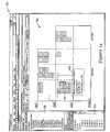
- FIG. 2is a diagram of a dialog box showing building information
- FIG. 3is a diagram of the dialog box showing more building information
- FIG. 4is a diagram of tree-map like facility model showing several floors and their respective areas
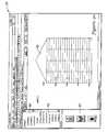
- FIG. 5is a diagram of a screen containing an insert of a table metaphor for creating a building with a capability for dragging a cell down or to the right to define a number of floors and areas, respectively;
- FIG. 6is a diagram showing a view of a facility model which may be modified
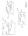
- FIG. 7is a diagram showing a plan view of the floors of the facility model where the shape, size and location of an area may be graphically changed;
- FIG. 8is a diagram showing how the tree-map view is adjusted to reflect a real space relationship among the areas of various floors
- FIG. 9is a diagram showing a screen on which objects can be displayed in various ways in a map view by clicking on a button that can, for instance, highlight or non-highlight, or show or hide, select or deselect a type of object in the map view to reveal various features of the object so as to help one to use a map view easily, and the objects may be displayed as labels and the same type of objects can be grouped together as a stack;
- FIG. 10is a diagram of a screen where there may be a defining object associations to a map view, for example, assigning a plant to a controller;
- FIG. 11is a diagram of a screen where assigning a plant to a controller may result in some contextual information about one or more of the items;
- FIG. 12is a diagram indicating that once an association is defined, such as that between a controller and a plant, the association may be reflected on the map view;
- FIG. 13is a diagram showing an assignment of devices to a controller and controllers to a network
- FIG. 14is a diagram showing objects which may be assigned to a certain channel where a connection line from the objects to the network channel may be auto-generated;
- FIG. 15is a diagram showing that by operating a map view, a riser diagram for a building or facility can be generated according to a predefined format
- FIG. 16is a high level diagram of a general data model of a map view
- FIG. 17shows a tree view, a facility model (map view) and a list view where data may be displayed and synchronized among views;
- FIG. 18is a diagram showing a concrete presentation of a building or facility model (map view), a list view and a tree view;
- FIG. 19is a diagram illustrating a facility that has multiple buildings
- FIG. 20is a diagram of a screen 21 showing a side map view of a building and revealing objects in it;
- FIG. 21is a diagram showing a map view of a building which may be navigated by a zoom and pan operation or by scroll bars, or by clicking on a target facility tree mode;
- FIG. 22is a diagram of various illustrative example presentations, although other kinds of presentations may be used, for facilitating design and analysis of a building structure.
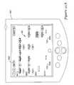
- FIGS. 23 a and 23 bare diagrams of a small screen or hand-held device, such as an illustrative example of a personal digital assistant (PDA), showing several kinds of map views of a building structure.
- PDApersonal digital assistant
- HVAC control solutionse.g., HVAC control solutions, fire detection and alarm systems, and so forth.
- a type of metaphoris to let users work with a tree structure.
- a large problem for users working with a tree structureis that the tree structure cannot indicate to users the space relationship of locations or objects. For example, when there are two tree nodes, a location A and a location B; users still do not necessarily know whether location A and location B are close to each other or far away. The same situation applies to a controller A and a controller B. Yet, this information is very critical to plan and design work. For example, without knowing a space relationship of the devices, users cannot know how the devices are distributed in the facility. Therefore, users cannot know how to distribute controllers and network, which devices are controlled by which controller, and so forth.
- CAD drawingsusually be used to get the space relationship, but this kind of cross reference may make the work inefficient, and CAD drawings may actually be an over-kill for this task.
- the tree structurecan be a very abstract view. This view does not necessarily provide users an intuitive way to plan and design various building systems efficiently and easily.
- CAD drawingsAnother type of metaphor needs users to work on CAD drawings in the CAD tools. For example, there may be ways that relate to a tool to help a user design various building systems, e.g., fire detection and alarm system.
- CAD toolse.g., AutoCAD tool
- CAD drawingsin the plan and design of various building systems.
- Usersmust be familiar with CAD tools, which may be burdensome to them. Some users may not be able to use CAD tools.
- CAD toolsmight be an overkill for satisfying users' needs in planning and designing an HVAC control solution, since there may be many unnecessary features which can lead to system performance issues.
- CAD drawings for a certain projectmay not necessarily be available, e.g., for a legacy project, often one cannot conveniently get just any CAD drawing. Users may need to go to the site to understand the facility model.
- working on CAD drawingsis not necessarily a good idea because of their high level of detail.
- a facility sitemay have multiple CAD drawings, e.g., one drawing for each floor.
- working on CAD drawingsdoes not necessarily provide a user the big picture. For example, when users need to deal with a cross floor situation, they may need to switch between different drawings back and forth which can be time consuming and inefficient.
- integrating with CAD toolsmay indicate a need to purchase a CAD tool which will increase the cost of a system design. Additionally, CAD drawings might be too complex to be displayed in the small screen devices.
- the present approachmay enable users to plan and design various building systems in an abstract and intuitive view, such as with a map view.
- virtually all facility informationis displayed as simple shapes (e.g., rectangles).
- Objectsi.e., devices and controllers
- Objectsmay be placed, moved around, and associated with each other on a facility layer.
- the table metaphor and wizardmay be provided for users to create shapes quickly and easily to reflect a facility model.
- Other featuresmay also be provided in this view to help users plan and design various building systems efficiently and easily, e.g., grouping similar objects to avoid visual clutter, contextual capacity information, to help the users assign objects to controllers, and so forth.
- map viewmay be used together with a tree view and a list view to provide different alternative design ways for users. Changes made in any of the views may be synchronized with other views.
- the map viewmay also be used in some small screen, mobile, permanently situated, or hand-held devices, such as for example a PDA. It may be easier for users to work with the map view in the small screen, mobile, permanently situated, or hand-held devices, rather than with a tree structure on a large display or CAD drawings.
- FIG. 1is a basic flow diagram of blocks in an order of 11 through 15 for a plan and design of a structure.
- a basic facility structuremay be created.
- shapes and their positions in the facilitymay be adjusted as needed, as indicated in block 12 .
- objects in a target locationmay be created. Associations of the objects may be defined according to block 14 .
- Related reports, drawings and a control programmay be generated at block 15 .
- Blocks 11 and 12may concern creating a facility model.
- Blocks 13 , 14 and 15may concern designing a control system.
- FIGS. 2-4show screens involving the use of wizard, one approach noted herein.
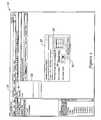
- FIG. 2shows a display or screen 21 .
- a usermay click on “Insert” 22 and select “Building” from a drop down menu 23 .
- the usermay command to create a building using the main menu in screen 21 , as shown.
- the usermay then define building information, for example, a building type and name, and a number of floors, at spaces 24 , 25 and 26 , respectively, of dialog box 27 .
- Dialog box 27 of FIG. 2shows step one of building information. Step two of building information may be shown by dialog box 27 in FIG. 3 .
- the number of areas required for each floormay be selected at space 28 .
- Each floormay be given a name in space 28 .
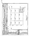
- the usermay click a “Finish” button 29 to display a created model building 34 in a small map view 31 in screen or display 21 of FIG. 4 .
- the usermay adjust the area layout in map view 31 .
- Another buildingmay be added by starting with a select click of a mouse cursor or arrow 41 on a button 32 in box 27 of screen 21 in FIG. 3 .
- View 31 in this Figuremay reveal the tree-map like facility model 34 showing first through third floors with areas A through L.
- a usermay modify facility model 34 .
- the usermay merge or split some areas, or delete or insert areas as shown by a mouse arrow 41 on block 35 .
- a palette 36shows a list revealing a tree of the project, the building name, e.g., “Gallia High School”, and the floors and the areas on each of the floors.
- FIG. 5shows screen 21 revealing a use of the table metaphor, a second approach for planning and designing a structure.
- the usermay obtain an insert table metaphor 38 and create a building by dragging a cell 39 down or to the right to define a number of floors and areas, respectively.
- FIG. 6shows a result which is a view 42 of a facility model 44 which may resemble model 34 in FIG. 4 .
- Model 44is a tree-like map which may be modified by merging or splitting some areas, or deleting or inserting areas as shown by mouse arrow 41 on block 35 .
- a tree of the facility model 44is shown in palette 36 of screen 21 in FIG. 6 .
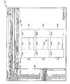
- FIG. 7indicates that the user may adjust the shape of each area and their locations to reflect their real space relationship, via a graphic editing technique.
- FIG. 7shows a plan view 52 of the floors of the facility model 44 .
- a usermay move and resize an area 45 , change the shape of the area by editing its vertex, moving one of the vertexes, and so on.
- the area 45may be listed as area G on the second floor.
- the adjacent areas E, F and Hbecome adjusted to maintain common walls relative to area 45 .
- FIG. 8shows the other first and third floors becoming adjusted to reflect the same floor plan of the vertically corresponding areas, so that the floors of the same building may be congruent relative to each other.
- the tree-map like viewmay be adjusted to reflect a real space relationship of the floors and areas.
- FIG. 9is a diagram showing a screen 21 on which objects can be displayed in various ways in a map view by clicking on a button that can, for instance, highlight, show or hide, or select or deselect a type of object in the map view to reveal various features of the object so as to help one to use a map view easily.
- the objectsmay be displayed as labels and the same type of objects can be grouped together as a stack.
- Object typesmay be differentiated by their shapes and colors.
- a usermay click on an object, such as a “VAV W/RH” 47 , to get a clearer view. Such click may result in a dialog box 48 which permits the object 47 or objects to be expanded as indicated by the mouse cursor 41 being clicked on label 49 entitled “Expand Group”.
- Other items which may be clicked on in box 48 relative to a selected objectmay involve “Assign to Network Channel”, “Collapse Group”, “Wiring type”, “New” and “Properties”.
- a usermay create a new object 51 and assign it to a target area 55 of, for example, level 1 .
- a usermay drag-and-drop a target object 51 from a library palette 54 to the target area 55 . Otherwise, the user may select the target area, such as area 55 as an instance, and then command to create a target object through a context menu.
- Each of the objects or devicesmay have a database associated which includes information like points, part number, standard control program, schematics, operator screen graphics, and so forth. This information may help to automatically generate many kinds of reports for a control solution.
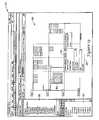
- a usermay define object associations to the map view; for example, assign a plant 56 to a controller 57 .
- Palette 36 of the tree listingshows the association of controller 57 with plant “AHU-1-01” 56 in an area B of the upper level in map view 53 .
- the systemmay provide the user some contextual information such as a point of connection, memory status, communication status, and so forth.
- An example of contextual informationis shown proximate to plant 56 and controller 57 .
- FIG. 12indicates that once an association is defined, such as that between controller 57 and plant 56 , it may be reflected on the map view 53 as well.
- associationsuch as that between controller 57 and plant 56 , it may be reflected on the map view 53 as well.
- FIG. 13Another example of association, in a network view 62 of FIG. 13 , a user may assign devices to a controller or assign controllers to a network.
- Network view 62 in FIG. 13is another version of map view 53 in preceding Figures.
- a dialog box 48may appear relative to, for instance, a controller, which has a label 61 “Assign to Network Channel” which might be extended to show a choice of channels.
- the choice in FIG. 13may consist of router A channel 1 and router A channel 2 . There may be other channels to choose from if a user so desires.
- FIG. 14is a diagram showing objects 64 which may be assigned to channel 1 of router A.
- the connection line from the objects 64 to the network channelmay be auto-generated based on a defined assignment or association.
- the systemmay provide contextual information 65 to facilitate the assignment or association.
- Information 65may indicate the assigned objects, bus traffic, a communication rate, and additional items as needed.
- FIG. 15reveals a riser diagram 66 of the facility.
- a riser diagrammay reveal components, such as devices and controllers, connection lines, and so forth in the areas of the floors.
- Diagram 66may be automatically generated by the system.
- Various reports, such as diagram 66 , drawings and a control programmay automatically be generated by the system.
- the diagramshows that by operating a map view, a riser diagram for a building or facility can be generated automatically according to a predefined format;
- FIG. 16is a high level diagram of a general data model of a map view.
- a map view 67may be presented in different ways. Examples of ways may consist of a network map or view, a riser view, a 3D perspective view, and so on.
- a facility 68Following map view 67 is a facility 68 .
- Facility 68may be a stadium, a building, or several buildings.
- Areas 69may follow facility 68 .
- An area 69may be multiple floors, one floor, several rooms or one room.
- One areamay contain other areas.
- Objects 71 and object groups 72may follow areas 69 .
- Objects 71may vary much for different building systems. For example, objects may be controllers, panels, plants, devices, and so on. For each object, its related data may be associated in the backend, such as a product number, data points, control programs, and so on.
- FIG. 17shows a tree view 73 , a facility model 74 and a list view 75 .
- Facility model 74may be like or regarded as a tree view. There may be an automatic generation and synchronization among and between tree view 73 , map view 74 and list view 75 .
- FIG. 17is an example of how data are displayed and synchronized among views 73 , 74 and 75 . Through the way presented, live data may be fed to map view 74 to show a dynamical presentation. Correlation of the nomenclature A 1 , A 2 , A 11 , A 12 , A 21 , A 22 , A 23 and Objects ⁇ 2 of view 73 may be noted relative to A 1 , A 2 , A 1 . 1 , A 1 . 2 , A 2 . 1 , A 2 . 2 , A 2 . 3 and Objects ⁇ 2 of views 74 and 75 .
- FIG. 18illustrates examples of three types of views—a traditional tree view example 76 , a map view example 77 and a list view example 78 .
- View 77may be a graphical view of a tree structure, a riser be or be like an abstract facility model, and be a complex building simply reduced into cross-sections which are rectangular.
- View 78as a list view, may be or be like an Excel spreadsheet integrated with a hierarchical structure.
- FIG. 19is a screen 21 which illustrates where one facility may have multiple buildings.
- building 81may be a school having three floors
- building 82may be a structure having six floors
- building 83may be an office building having twenty floors.
- FIG. 20is a screen 21 showing a side map view 86 of building 83 .
- a usermay command to display one of the buildings 81 , 82 and 83 , as in the present example.
- Devices in the displayed buildingmay be grouped and color coded according to their type.
- Objects inside a location of the buildingmay be automatically arranged to provide a clear view.
- Palette 87indicates an overview of the facility and the building selected for display.
- FIG. 21shows screen 21 showing detailed information of displayed building 83 .
- a usermay navigate to the target by a zoom and pan operation, or by scroll bars. Or instead, the user may navigate to the target by clicking on the facility tree mode. When zooming in a view of the target or a portion of it, more detailed information may be displayed. Floors between the fifth and eleventh are displayed in screen 21 .
- the overview palette 87 portion of screen 21may indicate a location 90 of the detailed portion of map view 86 .
- FIG. 22is a diagram of advanced presentations of a map view to facilitate design and analysis of a structure.
- Presentation 91may be regarded as a flat (default) map view of, for example, first and second floors 94 and 95 , respectively, of a building.
- the first floor 94may have objects 88 and 89 .
- the second floor 95may have objects 96 , 97 and 98 .
- Presentation 92may be regarded as a perspective map view of the first and second floors 94 and 95 with objects 88 , 89 , 96 , 97 and 98 .
- the perspective presentation 92may help to provide more vertical information about the floors and their respective objects.
- the perspective presentation of the floorsmay be at an angular view along an optical axis having an angle not parallel or vertical relative to a major surface of the respective floors.
- Presentation 93may be regarded as an overlay map view. Such presentation may help a user with some complex analysis and design relative to the floors and their objects.
- the overlapping plan viewsshow the objects of each floor with a graphic feature (e.g., color, shading, or shape) identifying the objects of each floor and objects of two or more floors having a vertical overlap.
- Floor 95appears overlaid on floor 94 .
- the objects of both floorsare shown.
- Object 89 of floor 94appears to be overlaid by object 97 of floor 95 .
- An example of overlaid objectsmay be sinks.
- One reason for sinks to overlay each othermay be the sinks can easily share common plumbing, i.e., water lines and drainage pipes.
- FIGS. 23 a and 23 bare diagrams showing an application of the present approach to mobile devices, e.g., a PDA.
- PDA 101 of FIG. 23 amay have an example map view similar to map view 53 of FIG. 9 .
- PDA 101 of FIG. 23 bmay show an example map view of the PDA of FIG. 23 a being zoomed in from 20% to 80% as noted by an indicator 102 .
- Map viewsshow illustrative example uses of PDA's. Map views may also be used in smart phones. Other mobile devices may be utilized for map views and design activities associated with them. In small screen mobile devices, a map view may show the relationship between areas and objects in an intuitive way. It should be much easier for a user to work on the map view, rather than on the tree-structure or CAD drawings.
- Tools 103including a drop-down menu 105 , and other menu 104 information may be available on mobile devices.
Landscapes
- Engineering & Computer Science (AREA)
- Physics & Mathematics (AREA)
- Geometry (AREA)
- Theoretical Computer Science (AREA)
- General Physics & Mathematics (AREA)
- Computer Hardware Design (AREA)
- Evolutionary Computation (AREA)
- General Engineering & Computer Science (AREA)
- Structural Engineering (AREA)
- Computational Mathematics (AREA)
- Civil Engineering (AREA)
- Mathematical Analysis (AREA)
- Mathematical Optimization (AREA)
- Pure & Applied Mathematics (AREA)
- Architecture (AREA)
- User Interface Of Digital Computer (AREA)
Abstract
Description
The invention pertains to building systems and particularly to planning, designing and observing building systems. More particularly, the invention pertains to tools for planning, designing and observing building systems.
The invention is an approach which may enable users to plan, design and observe various building systems in an abstract and intuitive view, such as with a map view. In this view, virtually all facility information and objects may be displayed as simple shapes (e.g., rectangles). Just by some drag-and-drop, a user may provide shapes and rearrange positions of these shapes quickly to reflect a desired space relationship. Objects (e.g., components, devices, controllers, and the like) may be placed, moved around, copied and duplicated, and associated with each other on a facility layer or floor. Further, the map view may be used together with a tree view and a list view to provide alternative design ways. Changes made in any of the views may be synchronized with the other views. Various presentations of the facility may be provided.
There are many tools designed to help users to plan and design various building systems, e.g., HVAC control solutions, fire detection and alarm systems, and so forth.
Generally, two types of metaphor are provided among existing tools. One type of metaphor is to let users work with a tree structure. A large problem for users working with a tree structure is that the tree structure cannot indicate to users the space relationship of locations or objects. For example, when there are two tree nodes, a location A and a location B; users still do not necessarily know whether location A and location B are close to each other or far away. The same situation applies to a controller A and a controller B. Yet, this information is very critical to plan and design work. For example, without knowing a space relationship of the devices, users cannot know how the devices are distributed in the facility. Therefore, users cannot know how to distribute controllers and network, which devices are controlled by which controller, and so forth. Usually, users will refer to CAD drawings to get the space relationship, but this kind of cross reference may make the work inefficient, and CAD drawings may actually be an over-kill for this task. In addition, the tree structure can be a very abstract view. This view does not necessarily provide users an intuitive way to plan and design various building systems efficiently and easily.
Another type of metaphor needs users to work on CAD drawings in the CAD tools. For example, there may be ways that relate to a tool to help a user design various building systems, e.g., fire detection and alarm system. However, there may be several issues for users to work relative to CAD tools (e.g., AutoCAD tool) and CAD drawings in the plan and design of various building systems. First, Users must be familiar with CAD tools, which may be burdensome to them. Some users may not be able to use CAD tools. Second, CAD tools might be an overkill for satisfying users' needs in planning and designing an HVAC control solution, since there may be many unnecessary features which can lead to system performance issues. Third, sometimes, the CAD drawings for a certain project may not necessarily be available, e.g., for a legacy project, often one cannot conveniently get just any CAD drawing. Users may need to go to the site to understand the facility model. Fourth, working on CAD drawings is not necessarily a good idea because of their high level of detail. Usually a facility site may have multiple CAD drawings, e.g., one drawing for each floor. In these cases, working on CAD drawings does not necessarily provide a user the big picture. For example, when users need to deal with a cross floor situation, they may need to switch between different drawings back and forth which can be time consuming and inefficient. Also, integrating with CAD tools may indicate a need to purchase a CAD tool which will increase the cost of a system design. Additionally, CAD drawings might be too complex to be displayed in the small screen devices.
In view of the issues listed herein, there appears to be a need to provide a graphical and intuitive metaphor for users to plan and design various building systems more efficiently with a big picture understanding having both a logical relationship and a spatial relationship.
The present approach may enable users to plan and design various building systems in an abstract and intuitive view, such as with a map view. In this view, virtually all facility information is displayed as simple shapes (e.g., rectangles). Just by some drag-and-drop, a user may rearrange the positions of these shapes quickly to reflect their space relationship. Objects (i.e., devices and controllers) may be placed, moved around, and associated with each other on a facility layer. Through this way, users may plan and design a building system graphically and intuitively, meanwhile, they can avoid the overwhelming information of other approaches such as those involving CAD tools.
Several approaches, for example, the table metaphor and wizard, may be provided for users to create shapes quickly and easily to reflect a facility model. Other features may also be provided in this view to help users plan and design various building systems efficiently and easily, e.g., grouping similar objects to avoid visual clutter, contextual capacity information, to help the users assign objects to controllers, and so forth.
Further, the present map view may be used together with a tree view and a list view to provide different alternative design ways for users. Changes made in any of the views may be synchronized with other views.
The map view may also be used in some small screen, mobile, permanently situated, or hand-held devices, such as for example a PDA. It may be easier for users to work with the map view in the small screen, mobile, permanently situated, or hand-held devices, rather than with a tree structure on a large display or CAD drawings.
To get alarge map view 31 of a facility model, the user may select or click abutton 33 entitled “Map View”, with themouse cursor 41 inscreen 21 ofFIG. 4 .View 31 in this Figure may reveal the tree-map likefacility model 34 showing first through third floors with areas A through L. A user may modifyfacility model 34. For example, the user may merge or split some areas, or delete or insert areas as shown by amouse arrow 41 onblock 35. Apalette 36 shows a list revealing a tree of the project, the building name, e.g., “Gallia High School”, and the floors and the areas on each of the floors.
In themap view 53, a user may create anew object 51 and assign it to a target area55 of, for example,level 1. A user may drag-and-drop atarget object 51 from alibrary palette 54 to the target area55. Otherwise, the user may select the target area, such as area55 as an instance, and then command to create a target object through a context menu.
Each of the objects or devices may have a database associated which includes information like points, part number, standard control program, schematics, operator screen graphics, and so forth. This information may help to automatically generate many kinds of reports for a control solution.
InFIG. 10 , a user may define object associations to the map view; for example, assign aplant 56 to acontroller 57.Palette 36 of the tree listing shows the association ofcontroller 57 with plant “AHU-1-01”56 in an area B of the upper level inmap view 53.
As indicated inFIG. 11 , when assigning a plant to a controller, the system may provide the user some contextual information such as a point of connection, memory status, communication status, and so forth. An example of contextual information is shown proximate to plant56 andcontroller 57.
Another example of association, in anetwork view 62 ofFIG. 13 , a user may assign devices to a controller or assign controllers to a network.Network view 62 inFIG. 13 is another version ofmap view 53 in preceding Figures. Adialog box 48 may appear relative to, for instance, a controller, which has alabel 61 “Assign to Network Channel” which might be extended to show a choice of channels. The choice inFIG. 13 may consist ofrouter A channel 1 androuter A channel 2. There may be other channels to choose from if a user so desires.
In the present specification, some of the matter may be of a hypothetical or prophetic nature although stated in another manner or tense.
Although the present system has been described with respect to at least one illustrative example, many variations and modifications will become apparent to those skilled in the art upon reading the specification. It is therefore the intention that the appended claims be interpreted as broadly as possible in view of the prior art to include all such variations and modifications.
Claims (21)
1. A computer-implemented method for designing a building system, comprising:
defining, using a computer, building information; and
developing, using the computer, building information; and
wherein:
defining, using the computer, building information comprises:
selecting a building from a category from a drop down menu on a display in communication with the computer;
selecting a type of building from a dialog box; and
selecting a building; and
developing, using the computer, building information comprises:
selecting a number of floors for the building from the dialog box;
in the dialog box, a user giving a name to each of the floors;
designating areas for each floor; and
further comprising:
representing the building and floors with a map view diagram shown on the display; and
dragging and dropping geometrical shapes on the diagram to represent objects in the building and to reflect space relationships among the objects and wherein if the building is represented with a tree view and a list view, then the map view can be automatically generated and synchronized with the tree view and list view.
2. The method ofclaim 1 , further comprising using an insert table metaphor in the display to select the number of floors and a number of areas by dragging a cell in the insert table.
3. The method ofclaim 1 , wherein:
the space relationships indicate the objects as distinguished from each other in the building; and
the objects are components, devices and controllers which can be placed, moved around, connected, and associated with each other.
4. The method ofclaim 1 , further comprising:
adjusting the shape, size, position and location of each area, as needed, on each floor; and
inserting, merging, splitting and/or deleting areas as needed.
5. The method ofclaim 4 , further comprising adjusting areas on various floors and their space relationship relative to areas on other floors so that the floors of the building are congruent, or otherwise, as desired, relative to each other.
6. The method ofclaim 1 , further comprising:
dragging and dropping geometrical shapes, representing one or more new objects, on an area of a floor in the diagram of the building; and
adjusting as needed a location of each new object after its representative shape has been dropped in an area.
7. The method ofclaim 6 , further comprising differentiating types of objects with graphical features on the geometrical shapes.
8. The method ofclaim 7 , further comprising:
expanding or collapsing a group of objects as necessary to obtain a clearer view of the objects in the display;
selecting or deselecting a type of objects; and
showing or hiding a type of objects.
9. The method ofclaim 7 , further comprising:
providing a database for information of each object;
defining associations of objects as represented in the map view diagram on the display; and
wherein:
an association of an object with another object can provide contextual information from the database of the one or more objects; and
contextual information comprises connection, memory status and communication status.
10. The method ofclaim 9 , wherein:
a connection among objects is auto-generated based on a defined association; and
the contextual information is provided for facilitating the defined association.
11. The method ofclaim 6 , wherein:
a riser diagram showing the objects and their connections is automatically generated; and
reports, drawings and a control program of the building are automatically generated.
12. A display view, displayed on a display in communication with a computer configured to execute instructions, for a building system comprising:
a map view of a building displayed on the display;
a tree view of the building displayed on the display; and
a list view of the building displayed on the display; and
wherein a computer executes instructions stored on a non-transitory computer readable medium to:
synchronize live data of all three views; and feed said synchronized live data to the map view to show a dynamical presentation.
13. The display view ofclaim 12 , wherein:
the tree view comprises different tree structures;
the map view is a tree map having a graphical view of a tree structure, riser-like abstract building model, and a building reduced into cross sections; and
the list view is a spreadsheet integrated with a hierarchical structure.
14. The display view ofclaim 12 , wherein:
one or more buildings are displayed;
a building has one or more locations in it;
the one or more locations have objects which can be automatically arranged as necessary for a clearer view of the objects; and
objects are grouped and graphically coded according to type.
15. The display view ofclaim 14 , wherein:
the one or more buildings, including locations and areas, can be navigated about on a display;
a user can navigate to a destination in the building on the display by a zoom and pan operation or by clicking on the destination; and
upon arriving at the destination, information about the destination is shown on the display.
16. A system for design and presentation, using a computer, of a building having two or more floors, comprising a design of the building presented with a tree view and a list view; wherein a map view of the building can be automatically generated and synchronized with the tree view and the list view:
a flat presentation of a building on a display in communication with a computer;
and
wherein the computer executes instructions stored on a non-transitory computer readable medium to show on the display of the flat presentation of a building:
a plan view for each floor of a design of a building; and
objects of the respective floors in the respective plan views of the design of the building.
17. The system ofclaim 16 , further comprising:
a perspective presentation of the design of the building on the display; and
wherein the computer executes instructions stored on a non-transitory computer readable medium to show on the display of the perspective presentation of the design of the building:
an angular view of the floors along an optical axis having an angle not parallel or vertical relative to a major surface of the respective floors; and
objects of the respective floors in a spatial relationship to each other.
18. The system ofclaim 17 , further comprising:
an overlay presentation of the design of the building on the display; and
wherein the computer executes instructions stored on a non-transitory computer readable medium to shown the display of the overlay presentation of the design of the building:
overlapping plan views of the floors; and
objects of each floor with a graphic feature identifying the objects of each floor and objects of two or more floors having a vertical overlap.
19. The system ofclaim 18 , wherein the flat presentation, the perspective presentation and the overlay presentation are used for viewing and designing the building and floors, and for placement of objects in the building.
20. The system ofclaim 18 , wherein:
the views, presentations and diagrams of the building or portions of the design of the building can be displayed on a screen of a small screen device;
zoom and navigation features of the small screen device can be applied to the views, presentations and diagrams; and
the small screen device can be a hand-held, mobile, or permanently situated device.
21. A computer-implemented method for designing a building system, comprising:
defining, using a computer, building information; and
developing, using the computer, building information; and
wherein:
defining, using the computer, building information comprises:
selecting a building from a category from a drop down menu on a display;
selecting a type of building from a dialog box; and
selecting a building; and
developing, using the computer, building information comprises:
selecting a number of floors for the building from the the dialog box;
naming the floors;
designating areas for each floor; and
further comprising:
representing the building and floors with a map view diagram shown on the display; and
dragging and dropping geometrical shapes on the diagram to represent objects in the building and to reflect space relationships among the objects; and
wherein if a building model and objects are generated from a list view or a tree view, then a map view of the building model and objects can be generated and synchronized with the tree view or list view.
Priority Applications (1)
| Application Number | Priority Date | Filing Date | Title |
|---|---|---|---|
| US12/646,416US8532962B2 (en) | 2009-12-23 | 2009-12-23 | Approach for planning, designing and observing building systems |
Applications Claiming Priority (1)
| Application Number | Priority Date | Filing Date | Title |
|---|---|---|---|
| US12/646,416US8532962B2 (en) | 2009-12-23 | 2009-12-23 | Approach for planning, designing and observing building systems |
Publications (2)
| Publication Number | Publication Date |
|---|---|
| US20110153279A1 US20110153279A1 (en) | 2011-06-23 |
| US8532962B2true US8532962B2 (en) | 2013-09-10 |
Family
ID=44152314
Family Applications (1)
| Application Number | Title | Priority Date | Filing Date |
|---|---|---|---|
| US12/646,416Active2031-10-05US8532962B2 (en) | 2009-12-23 | 2009-12-23 | Approach for planning, designing and observing building systems |
Country Status (1)
| Country | Link |
|---|---|
| US (1) | US8532962B2 (en) |
Cited By (21)
| Publication number | Priority date | Publication date | Assignee | Title |
|---|---|---|---|---|
| US20120259594A1 (en)* | 2011-04-08 | 2012-10-11 | Azam Khan | Bim based 3-d visualization |
| US20120296610A1 (en)* | 2011-05-17 | 2012-11-22 | Ebenezer Hailemariam | Occupant centric capture and visualization of building performance data |
| US20130246037A1 (en)* | 2012-03-15 | 2013-09-19 | Kenneth Paul Ceglia | Methods and apparatus for monitoring operation of a system asset |
| US20130338969A1 (en)* | 2012-06-14 | 2013-12-19 | Paul Landes | Structural Representation and Facilitation of Manipulation Thereof Via Implicit Vertex Relationships |
| US9262048B1 (en)* | 2014-01-21 | 2016-02-16 | Utec Survey, Inc. | System for monitoring and displaying a plurality of tagged telecommunication assets |
| US9374870B2 (en) | 2012-09-12 | 2016-06-21 | Sensity Systems Inc. | Networked lighting infrastructure for sensing applications |
| US9456293B2 (en) | 2013-03-26 | 2016-09-27 | Sensity Systems Inc. | Sensor nodes with multicast transmissions in lighting sensory network |
| US9582671B2 (en) | 2014-03-06 | 2017-02-28 | Sensity Systems Inc. | Security and data privacy for lighting sensory networks |
| US9619124B2 (en) | 2013-06-10 | 2017-04-11 | Honeywell International Inc. | Frameworks, devices and methods configured for enabling gesture-based controlled display for facility information and content in respect of a multi-level facility |
| US9672006B2 (en) | 2013-06-10 | 2017-06-06 | Honeywell International Inc. | Frameworks, devices and methods configured for enabling a multi-modal user interface configured to display facility information |
| US9746370B2 (en) | 2014-02-26 | 2017-08-29 | Sensity Systems Inc. | Method and apparatus for measuring illumination characteristics of a luminaire |
| US9804735B2 (en) | 2013-06-10 | 2017-10-31 | Honeywell International Inc. | Frameworks, devices and methods configured for enabling transition of content in a user interface between a map-bound layer and a map-unbound layer |
| US9933297B2 (en) | 2013-03-26 | 2018-04-03 | Sensity Systems Inc. | System and method for planning and monitoring a light sensory network |
| US10362112B2 (en) | 2014-03-06 | 2019-07-23 | Verizon Patent And Licensing Inc. | Application environment for lighting sensory networks |
| US10417570B2 (en) | 2014-03-06 | 2019-09-17 | Verizon Patent And Licensing Inc. | Systems and methods for probabilistic semantic sensing in a sensory network |
| US10474240B2 (en) | 2013-06-10 | 2019-11-12 | Honeywell International Inc. | Frameworks, devices and methods configured for enabling gesture-based interaction between a touch/gesture controlled display and other networked devices |
| US20210200910A1 (en)* | 2018-09-13 | 2021-07-01 | Carrier Corporation | Fire detection system tool for constraint compliant placement of fire equipment |
| US11086491B1 (en) | 2020-01-21 | 2021-08-10 | Honeywell International Inc. | Systems and methods for displaying video streams on a display |
| US11397519B2 (en)* | 2019-11-27 | 2022-07-26 | Sap Se | Interface controller and overlay |
| US11511142B2 (en) | 2018-09-13 | 2022-11-29 | Carrier Corporation | Fire detection system—end-to-end solution for fire detection design framework |
| US11977805B2 (en) | 2014-11-12 | 2024-05-07 | Honeywell International Inc. | Systems and methods for displaying facility information |
Families Citing this family (27)
| Publication number | Priority date | Publication date | Assignee | Title |
|---|---|---|---|---|
| US8990049B2 (en) | 2010-05-03 | 2015-03-24 | Honeywell International Inc. | Building structure discovery and display from various data artifacts at scene |
| US8538687B2 (en) | 2010-05-04 | 2013-09-17 | Honeywell International Inc. | System for guidance and navigation in a building |
| US8773946B2 (en) | 2010-12-30 | 2014-07-08 | Honeywell International Inc. | Portable housings for generation of building maps |
| US9342928B2 (en) | 2011-06-29 | 2016-05-17 | Honeywell International Inc. | Systems and methods for presenting building information |
| US8621394B2 (en) | 2011-08-26 | 2013-12-31 | Nokia Corporation | Method, apparatus and computer program product for displaying items on multiple floors in multi-level maps |
| AU2013203521B2 (en) | 2012-08-13 | 2016-05-26 | Auto-Measure Pty Limited | Building modelling system |
| US20140068445A1 (en)* | 2012-09-06 | 2014-03-06 | Sap Ag | Systems and Methods for Mobile Access to Enterprise Work Area Information |
| US9058583B2 (en) | 2012-09-06 | 2015-06-16 | Sap Se | Systems and methods for mobile access to item information |
| US8947437B2 (en)* | 2012-09-15 | 2015-02-03 | Honeywell International Inc. | Interactive navigation environment for building performance visualization |
| KR102015586B1 (en)* | 2013-04-23 | 2019-08-28 | 한화테크윈 주식회사 | Apparatus for automatic mapping of monitoring and control point for energy management of the large complex building in a graphic widget |
| KR101912795B1 (en)* | 2013-04-29 | 2018-10-29 | 한화테크윈 주식회사 | 3D building information providing device |
| US10114537B2 (en) | 2013-06-10 | 2018-10-30 | Honeywell International Inc. | Frameworks, devices and methods configured for enabling touch/gesture controlled display for facility information and content with resolution dependent display and persistent content positioning |
| US10454783B2 (en) | 2014-02-05 | 2019-10-22 | Apple Inc. | Accessory management system using environment model |
| US10177933B2 (en) | 2014-02-05 | 2019-01-08 | Apple Inc. | Controller networks for an accessory management system |
| EP3493509B1 (en) | 2014-02-05 | 2020-10-21 | Apple Inc. | Uniform communication protocols for communication between controllers and accessories |
| CN106462123B (en)* | 2014-05-30 | 2020-12-22 | 苹果公司 | Attachment management system using environment model |
| US10206170B2 (en) | 2015-02-05 | 2019-02-12 | Apple Inc. | Dynamic connection path detection and selection for wireless controllers and accessories |
| US10831332B2 (en)* | 2017-02-23 | 2020-11-10 | The Florida International University Board Of Trustees | User interface element for building interior previewing and navigation |
| CN107132968A (en)* | 2017-04-27 | 2017-09-05 | 上海烟草集团有限责任公司 | System for carrying out planar hull modelling to spatial scene |
| US20180314408A1 (en)* | 2017-04-28 | 2018-11-01 | General Electric Company | Systems and methods for managing views of computer-aided design models |
| JP6957977B2 (en)* | 2017-05-25 | 2021-11-02 | 富士通株式会社 | Information processing device, installation position determination program and its method |
| US10496508B2 (en) | 2017-06-02 | 2019-12-03 | Apple Inc. | Accessory communication control |
| US11805009B2 (en) | 2018-06-03 | 2023-10-31 | Apple Inc. | Configuring accessory network connections |
| US10595073B2 (en) | 2018-06-03 | 2020-03-17 | Apple Inc. | Techniques for authorizing controller devices |
| CN110895614A (en) | 2018-09-13 | 2020-03-20 | 开利公司 | Fire Extinguishing System-Pipeline Design AI Aid and Visualization Tool |
| CN110895619A (en) | 2018-09-13 | 2020-03-20 | 开利公司 | Fire extinguishing system-end-to-end solution for fire extinguishing sales and design |
| CN110895632A (en) | 2018-09-13 | 2020-03-20 | 开利公司 | Fire Extinguishing System - System and Method for Optimal Nozzle Placement |
Citations (123)
| Publication number | Priority date | Publication date | Assignee | Title |
|---|---|---|---|---|
| US5719561A (en) | 1995-10-25 | 1998-02-17 | Gilbert R. Gonzales | Tactile communication device and method |
| US5745126A (en) | 1995-03-31 | 1998-04-28 | The Regents Of The University Of California | Machine synthesis of a virtual video camera/image of a scene from multiple video cameras/images of the scene in accordance with a particular perspective on the scene, an object in the scene, or an event in the scene |
| US5857986A (en) | 1996-05-24 | 1999-01-12 | Moriyasu; Hiro | Interactive vibrator for multimedia |
| US6006161A (en) | 1996-08-02 | 1999-12-21 | Aisin Aw Co., Ltd. | Land vehicle navigation system with multi-screen mode selectivity |
| US6334211B1 (en) | 1989-09-29 | 2001-12-25 | Hitachi, Ltd. | Method for visual programming with aid of animation |
| JP2001356813A (en) | 2000-06-14 | 2001-12-26 | Chiyoda Corp | Plant maintenance support system |
| US20020055384A1 (en) | 1992-03-05 | 2002-05-09 | Armstrong Brad A. | Proportional controls used with displayed imagery |
| US20030083957A1 (en) | 1995-06-16 | 2003-05-01 | Shari B. Olefson | Method and apparatus for selection and viewing real estate properties |
| US20030214400A1 (en) | 2002-05-16 | 2003-11-20 | Fujitsu Limited | Monitoring system realizing high performance with reduced processing loads |
| US20040021569A1 (en) | 2001-11-21 | 2004-02-05 | Robert Lepkofker | Personnel and resource tracking method and system for enclosed spaces |
| US6710706B1 (en) | 1997-12-09 | 2004-03-23 | Sound Foresight Limited | Spatial awareness device |
| US6720921B2 (en) | 2002-02-15 | 2004-04-13 | Allen E. Ripingill, Jr. | Position location and tracking method and system employing low frequency radio signal processing |
| US20040233192A1 (en) | 2003-05-22 | 2004-11-25 | Hopper Stephen A. | Focally-controlled imaging system and method |
| US20050010460A1 (en) | 2003-02-12 | 2005-01-13 | Masanobu Mizoguchi | Facilities control system and method of controlling facilities |
| US6876951B2 (en) | 1998-12-29 | 2005-04-05 | Wireless Valley Communications, Inc. | Method for creating a computer model and measurement database of a wireless communication network |
| WO2005033912A2 (en)* | 2003-03-28 | 2005-04-14 | Designquik L.L.C. | Integrated computer aided design tool |
| US6900762B2 (en) | 2002-09-30 | 2005-05-31 | Lucent Technologies Inc. | Methods and apparatus for location determination based on dispersed radio frequency tags |
| US6924787B2 (en) | 2000-04-17 | 2005-08-02 | Immersion Corporation | Interface for controlling a graphical image |
| JP2005242531A (en) | 2004-02-25 | 2005-09-08 | Hitachi Ltd | Installation work management system using 3D-CAD |
| JP2005311563A (en) | 2004-04-20 | 2005-11-04 | Victor Co Of Japan Ltd | Monitoring method |
| US6965312B2 (en) | 1999-06-07 | 2005-11-15 | Traptec Corporation | Firearm shot helmet detection system and method of use |
| US20050264558A1 (en) | 2004-06-01 | 2005-12-01 | Vesely Michael A | Multi-plane horizontal perspective hands-on simulator |
| US20050267900A1 (en) | 2004-03-30 | 2005-12-01 | Osman Ahmed | Method and system for organizing data relating to a home |
| US20060009862A1 (en) | 2004-06-28 | 2006-01-12 | Raphael Imhof | Method and apparatus for accessing a building system model |
| US20060029256A1 (en) | 2004-08-09 | 2006-02-09 | Takashi Miyoshi | Method of generating image and device |
| US7002551B2 (en) | 2002-09-25 | 2006-02-21 | Hrl Laboratories, Llc | Optical see-through augmented reality modified-scale display |
| US20060044307A1 (en) | 2004-08-24 | 2006-03-02 | Kyuman Song | System and method for visually representing project metrics on 3-dimensional building models |
| US20060061752A1 (en) | 2004-07-11 | 2006-03-23 | Rafael-Armament Development Authority Ltd. | Information sensing and sharing system for supporting rescue operations from burning buildings |
| US20060073455A1 (en) | 2004-09-30 | 2006-04-06 | Cardiac Pacemakers, Inc. | Virtual reality based prototyping system for medical devices |
| US7062722B1 (en) | 2000-08-22 | 2006-06-13 | Bruce Carlin | Network-linked interactive three-dimensional composition and display of saleable objects in situ in viewer-selected scenes for purposes of promotion and procurement |
| US7096120B2 (en) | 2002-08-06 | 2006-08-22 | Hewlett-Packard Development Company, L.P. | Method and arrangement for guiding a user along a target path |
| US7102510B2 (en) | 2003-06-03 | 2006-09-05 | Procon, Inc. | Asset location tracking system |
| US7111783B2 (en) | 2004-06-25 | 2006-09-26 | Board Of Trustees Operating Michigan State University | Automated dimensional inspection |
| US7132928B2 (en) | 2003-10-01 | 2006-11-07 | Perricone Nicholas V | Threat detection system interface |
| US7139685B2 (en) | 2000-11-03 | 2006-11-21 | Siemens Aktiengesellschaft | Video-supported planning of equipment installation and/or room design |
| US20060265664A1 (en)* | 2005-05-17 | 2006-11-23 | Hitachi, Ltd. | System, method and computer program product for user interface operations for ad-hoc sensor node tracking |
| US7146218B2 (en) | 2000-12-12 | 2006-12-05 | The Trustees Of The University Of Pennsylvania | Adaptive method and apparatus for forecasting and controlling neurological disturbances under a multi-level control |
| US20060282235A1 (en)* | 2001-05-15 | 2006-12-14 | Metron Media, Inc. | System for creating measured drawings |
| US20070001904A1 (en) | 2005-05-09 | 2007-01-04 | Ehud Mendelson | System and method navigating indoors and outdoors without GPS. utilizing a network of sensors |
| US7200639B1 (en) | 1999-11-15 | 2007-04-03 | International Bussiness Machines Corporation | Remote control system, server-client system, server for controlling terminal device, terminal device operating method, device information sharing method, storage media, and program transmission apparatus |
| US7246044B2 (en)* | 2000-09-13 | 2007-07-17 | Matsushita Electric Works, Ltd. | Method for aiding space design using network, system therefor, and server computer of the system |
| US7246008B2 (en) | 2001-09-12 | 2007-07-17 | General Electric Company | High resolution tracking of mobile assets |
| JP2007183432A (en) | 2006-01-06 | 2007-07-19 | Toyota Motor Corp | Automatic travel map creation device and automatic travel device. |
| US20070201421A1 (en) | 2005-12-09 | 2007-08-30 | Honeywell International, Inc. | Method and apparatus for location estimation |
| US20070205886A1 (en) | 2006-03-01 | 2007-09-06 | Huseth Steve D | RF/acoustic person locator system |
| US20070239352A1 (en) | 2006-04-10 | 2007-10-11 | Microsoft Corporation | Embedded dynamic map generation |
| US20070239350A1 (en) | 2006-04-07 | 2007-10-11 | Zumsteg Philip J | Multi-function tracking device with robust asset tracking system |
| US20070250199A1 (en)* | 1999-08-31 | 2007-10-25 | Shingo Akasaka | Remote order acceptance design system and elevator remote order acceptance method |
| US7292908B2 (en) | 2004-10-13 | 2007-11-06 | Robotic Built Structures, Inc. | Systems and methods for manufacturing customized prefabricated buildings including arbitrarily modularizing a building specification without using any pre-defined modules |
| US7301648B2 (en) | 2000-01-28 | 2007-11-27 | Intersense, Inc. | Self-referenced tracking |
| US7304442B2 (en) | 2003-12-02 | 2007-12-04 | Walter R. Colwell | Three component protective head gear powered by a rechargeable battery |
| US20070279210A1 (en) | 2006-06-06 | 2007-12-06 | Honeywell International Inc. | Time-dependent classification and signaling of evacuation route safety |
| US7308323B2 (en) | 2004-09-10 | 2007-12-11 | Siemens Building Technologies, Inc. | Configuration output system |
| JP2007333998A (en) | 2006-06-15 | 2007-12-27 | Hitachi Ltd | Automatic map generator |
| US20080033645A1 (en) | 2006-08-03 | 2008-02-07 | Jesse Sol Levinson | Pobabilistic methods for mapping and localization in arbitrary outdoor environments |
| US20080040669A1 (en) | 2006-08-08 | 2008-02-14 | Honeywell International Inc. | Audio-based presentation system |
| US20080062167A1 (en) | 2006-09-13 | 2008-03-13 | International Design And Construction Online, Inc. | Computer-based system and method for providing situational awareness for a structure using three-dimensional modeling |
| US20080068267A1 (en) | 2006-09-14 | 2008-03-20 | Huseth Steve D | Cost effective communication infrastructure for location sensing |
| US20080077326A1 (en) | 2006-05-31 | 2008-03-27 | Funk Benjamin E | Method and System for Locating and Monitoring First Responders |
| US7358458B2 (en) | 2005-01-25 | 2008-04-15 | Lincoln Global, Inc. | Methods and apparatus for tactile communication in an arc processing system |
| US20080122696A1 (en) | 2006-11-28 | 2008-05-29 | Huseth Steve D | Low cost fire fighter tracking system |
| US7383148B2 (en) | 2004-03-25 | 2008-06-03 | Siemens Building Technologies, Inc. | Method and apparatus for graphically displaying a building system |
| US7382281B2 (en) | 2004-03-01 | 2008-06-03 | Sensys Networks, Inc. | Method and apparatus reporting a vehicular sensor waveform in a wireless vehicular sensor network |
| US7389207B2 (en) | 2000-12-08 | 2008-06-17 | Tracker R & D, Llc | System for dynamic and automatic building mapping |
| US20080158256A1 (en) | 2006-06-26 | 2008-07-03 | Lockheed Martin Corporation | Method and system for providing a perspective view image by intelligent fusion of a plurality of sensor data |
| US7420510B2 (en) | 2006-04-17 | 2008-09-02 | Honeywell International Inc. | Location and tracking of people with combined use of RF infrastructure and dead reckoning modules |
| US20080215524A1 (en) | 2006-05-02 | 2008-09-04 | Tele Atlas North America, Inc. | System and method for associating geographic location information from multiple sources |
| US20080220780A1 (en) | 2007-03-07 | 2008-09-11 | Honeywell International Inc. | Method for the automatic calibration of location anchors |
| US20080228039A1 (en) | 2007-03-12 | 2008-09-18 | Honeywell International Inc. | Semi-passive method and system for monitoring and determining the status of an unattended person |
| US20090040175A1 (en) | 2004-12-22 | 2009-02-12 | Rex Fang Xu | Input interface device with transformable form factor |
| US20090043504A1 (en) | 2007-05-31 | 2009-02-12 | Amrit Bandyopadhyay | System and method for locating, tracking, and/or monitoring the status of personnel and/or assets both indoors and outdoors |
| US20090046140A1 (en) | 2005-12-06 | 2009-02-19 | Microvision, Inc. | Mobile Virtual Reality Projector |
| US20090044808A1 (en) | 2007-07-30 | 2009-02-19 | Resmed Limited | Patient interface |
| US7496445B2 (en) | 2005-04-27 | 2009-02-24 | Proxemics, Llc | Wayfinding |
| US7512450B2 (en) | 2004-03-25 | 2009-03-31 | Siemens Building Technologies, Inc. | Method and apparatus for generating a building system model |
| US20090105006A1 (en) | 2007-10-23 | 2009-04-23 | Doyle Robert S | Training Apparatus for improving a golf swing |
| US7548833B2 (en) | 2004-03-25 | 2009-06-16 | Siemens Building Technologies, Inc. | Method and apparatus for graphical display of a condition in a building system with a mobile display unit |
| US7567844B2 (en) | 2006-03-17 | 2009-07-28 | Honeywell International Inc. | Building management system |
| US20090216775A1 (en) | 2008-02-22 | 2009-08-27 | Marc Gregory Ratliff | Platform for real-time tracking and analysis |
| US20090216438A1 (en) | 2008-02-21 | 2009-08-27 | Microsoft Corporation | Facility map framework |
| US7583275B2 (en) | 2002-10-15 | 2009-09-01 | University Of Southern California | Modeling and video projection for augmented virtual environments |
| US7596473B2 (en) | 2003-05-20 | 2009-09-29 | Interlego Ag | Method of constructing a virtual construction model |
| US7606579B2 (en) | 2005-12-01 | 2009-10-20 | Discrete Wireless, Inc. | Auto mapping through location based triggers |
| US20090265104A1 (en) | 2008-04-22 | 2009-10-22 | Itt Manufacturing Enterprises, Inc. | Navigation System and Method of Obtaining Accurate Navigational Information in Signal Challenging Environments |
| US7610910B2 (en) | 2004-03-25 | 2009-11-03 | Siemens Building Technologies, Inc. | Method and apparatus for controlling building component characteristics |
| US7612832B2 (en) | 2005-03-29 | 2009-11-03 | Microsoft Corporation | Method and system for video clip compression |
| US20090298024A1 (en) | 2008-05-28 | 2009-12-03 | Todd Batzler | Welding training system |
| US20090307255A1 (en)* | 2008-06-06 | 2009-12-10 | Johnson Controls Technology Company | Graphical management of building devices |
| US20100057354A1 (en) | 2008-08-28 | 2010-03-04 | Henry Chen | Method of Route Retrieval |
| US7715980B2 (en) | 2005-11-17 | 2010-05-11 | Microsoft Corporation | Schematic destination maps |
| GB2441434B (en) | 2006-08-29 | 2010-06-23 | David Charles Dewhurst | Audiotactile vision substitution system |
| US7764220B1 (en) | 2009-04-22 | 2010-07-27 | Raytheon Company | Synthetic aperture radar incorporating height filtering for use with land-based vehicles |
| US7774075B2 (en) | 2002-11-06 | 2010-08-10 | Lin Julius J Y | Audio-visual three-dimensional input/output |
| US7777666B2 (en) | 2008-06-04 | 2010-08-17 | Honeywell International Inc. | Celestial body mapping systems and methods |
| US7830250B2 (en) | 2007-10-22 | 2010-11-09 | Honeywell International Inc. | Apparatus and method for location estimation using power supply voltage levels of signal transmitters |
| US20100299065A1 (en) | 2008-07-25 | 2010-11-25 | Mays Joseph P | Link-node maps based on open area maps |
| US20110010134A1 (en)* | 2009-07-08 | 2011-01-13 | Graphisoft | Active building information modeling apparatus and method |
| US7898468B2 (en) | 2008-02-14 | 2011-03-01 | Raytheon Company | Radar imaging of buildings using model-based focusing and data-based focusing |
| US20110059698A1 (en) | 2008-04-10 | 2011-03-10 | Honeywell International Inc. | System and method for calibration of radio frequency location sensors |
| US20110082643A1 (en) | 2009-10-05 | 2011-04-07 | Honeywell International Inc. | Location enhancement system and method based on topology constraints |
| US20110112875A1 (en) | 2009-11-12 | 2011-05-12 | Bank Of America Corporation | Site survey and installation for remote facility management system |
| US20110137549A1 (en) | 2009-12-09 | 2011-06-09 | Qualcomm Incorporated | Method and apparatus for reducing instructions in an indoor navigation environment |
| US7962150B2 (en) | 2004-04-28 | 2011-06-14 | Lawrence Livermore National Security, Llc | Ultra-wideband radios for time-of-flight-ranging and network position estimation |
| US7973669B2 (en) | 2007-08-23 | 2011-07-05 | Honeywell International Inc. | Apparatus and method for wireless location sensing |
| US20110164768A1 (en) | 2010-01-06 | 2011-07-07 | Honeywell International Inc. | Acoustic user interface system and method for providing spatial location data |
| US7982614B2 (en) | 2008-08-18 | 2011-07-19 | Honeywell International Inc. | Method and apparatus for wireless asset tracking using asset tags with motion sensors |
| US8000892B2 (en) | 2007-06-12 | 2011-08-16 | Campus Destinations, Inc. | Pedestrian mapping system |
| US20110248847A1 (en) | 2010-04-08 | 2011-10-13 | Honeywell International Inc. | Mobile asset location in structure |
| US8041744B2 (en) | 2004-06-24 | 2011-10-18 | Tekla Corporation | Computer-aided modeling |
| US8040273B2 (en) | 2009-07-14 | 2011-10-18 | Raytheon Company | Radar for imaging of buildings |
| US20110268300A1 (en) | 2010-04-30 | 2011-11-03 | Honeywell International Inc. | Tactile-based guidance system |
| US20110270584A1 (en) | 2010-05-03 | 2011-11-03 | Honeywell International Inc. | Building structure discovery and display from various data artifacts at scene |
| US20110276264A1 (en) | 2010-05-04 | 2011-11-10 | Honeywell International Inc. | System for guidance and navigation in a building |
| US20110285851A1 (en) | 2010-05-20 | 2011-11-24 | Honeywell International Inc. | Intruder situation awareness system |
| US8089407B2 (en) | 2005-12-16 | 2012-01-03 | Alcatel Lucent | System and method for model-free position estimation and tracking |
| US8102423B2 (en) | 2004-08-10 | 2012-01-24 | Sri International | Method and system for performing adaptive image acquisition |
| US20120143495A1 (en) | 2010-10-14 | 2012-06-07 | The University Of North Texas | Methods and systems for indoor navigation |
| US20120173204A1 (en) | 2010-12-30 | 2012-07-05 | Honeywell International Inc. | Building map generation using location and tracking data |
| US20120169530A1 (en) | 2010-12-30 | 2012-07-05 | Honeywell International Inc. | Portable housings for generation of building maps |
| US20120194517A1 (en) | 2011-01-31 | 2012-08-02 | Microsoft Corporation | Using a Three-Dimensional Environment Model in Gameplay |
| US8279119B2 (en) | 2005-01-19 | 2012-10-02 | The Charles Stark Draper Laboratory, Inc. | Systems and methods for transparency mapping using multipath signals |
| US8289390B2 (en) | 2004-07-28 | 2012-10-16 | Sri International | Method and apparatus for total situational awareness and monitoring |
| US20120319903A1 (en) | 2011-06-15 | 2012-12-20 | Honeywell International Inc. | System and method for locating mobile devices |
- 2009
- 2009-12-23USUS12/646,416patent/US8532962B2/enactiveActive
Patent Citations (133)
| Publication number | Priority date | Publication date | Assignee | Title |
|---|---|---|---|---|
| US6334211B1 (en) | 1989-09-29 | 2001-12-25 | Hitachi, Ltd. | Method for visual programming with aid of animation |
| US20020055384A1 (en) | 1992-03-05 | 2002-05-09 | Armstrong Brad A. | Proportional controls used with displayed imagery |
| US5745126A (en) | 1995-03-31 | 1998-04-28 | The Regents Of The University Of California | Machine synthesis of a virtual video camera/image of a scene from multiple video cameras/images of the scene in accordance with a particular perspective on the scene, an object in the scene, or an event in the scene |
| US20030083957A1 (en) | 1995-06-16 | 2003-05-01 | Shari B. Olefson | Method and apparatus for selection and viewing real estate properties |
| US5719561A (en) | 1995-10-25 | 1998-02-17 | Gilbert R. Gonzales | Tactile communication device and method |
| US5857986A (en) | 1996-05-24 | 1999-01-12 | Moriyasu; Hiro | Interactive vibrator for multimedia |
| US6006161A (en) | 1996-08-02 | 1999-12-21 | Aisin Aw Co., Ltd. | Land vehicle navigation system with multi-screen mode selectivity |
| US6710706B1 (en) | 1997-12-09 | 2004-03-23 | Sound Foresight Limited | Spatial awareness device |
| US6876951B2 (en) | 1998-12-29 | 2005-04-05 | Wireless Valley Communications, Inc. | Method for creating a computer model and measurement database of a wireless communication network |
| US6965312B2 (en) | 1999-06-07 | 2005-11-15 | Traptec Corporation | Firearm shot helmet detection system and method of use |
| US20070250199A1 (en)* | 1999-08-31 | 2007-10-25 | Shingo Akasaka | Remote order acceptance design system and elevator remote order acceptance method |
| US7200639B1 (en) | 1999-11-15 | 2007-04-03 | International Bussiness Machines Corporation | Remote control system, server-client system, server for controlling terminal device, terminal device operating method, device information sharing method, storage media, and program transmission apparatus |
| US7301648B2 (en) | 2000-01-28 | 2007-11-27 | Intersense, Inc. | Self-referenced tracking |
| US6924787B2 (en) | 2000-04-17 | 2005-08-02 | Immersion Corporation | Interface for controlling a graphical image |
| JP2001356813A (en) | 2000-06-14 | 2001-12-26 | Chiyoda Corp | Plant maintenance support system |
| US7062722B1 (en) | 2000-08-22 | 2006-06-13 | Bruce Carlin | Network-linked interactive three-dimensional composition and display of saleable objects in situ in viewer-selected scenes for purposes of promotion and procurement |
| US7246044B2 (en)* | 2000-09-13 | 2007-07-17 | Matsushita Electric Works, Ltd. | Method for aiding space design using network, system therefor, and server computer of the system |
| US7139685B2 (en) | 2000-11-03 | 2006-11-21 | Siemens Aktiengesellschaft | Video-supported planning of equipment installation and/or room design |
| US7389207B2 (en) | 2000-12-08 | 2008-06-17 | Tracker R & D, Llc | System for dynamic and automatic building mapping |
| US7146218B2 (en) | 2000-12-12 | 2006-12-05 | The Trustees Of The University Of Pennsylvania | Adaptive method and apparatus for forecasting and controlling neurological disturbances under a multi-level control |
| US20060282235A1 (en)* | 2001-05-15 | 2006-12-14 | Metron Media, Inc. | System for creating measured drawings |
| US7246008B2 (en) | 2001-09-12 | 2007-07-17 | General Electric Company | High resolution tracking of mobile assets |
| US20040021569A1 (en) | 2001-11-21 | 2004-02-05 | Robert Lepkofker | Personnel and resource tracking method and system for enclosed spaces |
| US6720921B2 (en) | 2002-02-15 | 2004-04-13 | Allen E. Ripingill, Jr. | Position location and tracking method and system employing low frequency radio signal processing |
| US20030214400A1 (en) | 2002-05-16 | 2003-11-20 | Fujitsu Limited | Monitoring system realizing high performance with reduced processing loads |
| US7096120B2 (en) | 2002-08-06 | 2006-08-22 | Hewlett-Packard Development Company, L.P. | Method and arrangement for guiding a user along a target path |
| US7002551B2 (en) | 2002-09-25 | 2006-02-21 | Hrl Laboratories, Llc | Optical see-through augmented reality modified-scale display |
| US6900762B2 (en) | 2002-09-30 | 2005-05-31 | Lucent Technologies Inc. | Methods and apparatus for location determination based on dispersed radio frequency tags |
| US7583275B2 (en) | 2002-10-15 | 2009-09-01 | University Of Southern California | Modeling and video projection for augmented virtual environments |
| US7774075B2 (en) | 2002-11-06 | 2010-08-10 | Lin Julius J Y | Audio-visual three-dimensional input/output |
| US20050010460A1 (en) | 2003-02-12 | 2005-01-13 | Masanobu Mizoguchi | Facilities control system and method of controlling facilities |
| WO2005033912A2 (en)* | 2003-03-28 | 2005-04-14 | Designquik L.L.C. | Integrated computer aided design tool |
| US7596473B2 (en) | 2003-05-20 | 2009-09-29 | Interlego Ag | Method of constructing a virtual construction model |
| US20040233192A1 (en) | 2003-05-22 | 2004-11-25 | Hopper Stephen A. | Focally-controlled imaging system and method |
| US7102510B2 (en) | 2003-06-03 | 2006-09-05 | Procon, Inc. | Asset location tracking system |
| US7132928B2 (en) | 2003-10-01 | 2006-11-07 | Perricone Nicholas V | Threat detection system interface |
| US7304442B2 (en) | 2003-12-02 | 2007-12-04 | Walter R. Colwell | Three component protective head gear powered by a rechargeable battery |
| JP2005242531A (en) | 2004-02-25 | 2005-09-08 | Hitachi Ltd | Installation work management system using 3D-CAD |
| US7382281B2 (en) | 2004-03-01 | 2008-06-03 | Sensys Networks, Inc. | Method and apparatus reporting a vehicular sensor waveform in a wireless vehicular sensor network |
| US7383148B2 (en) | 2004-03-25 | 2008-06-03 | Siemens Building Technologies, Inc. | Method and apparatus for graphically displaying a building system |
| US7610910B2 (en) | 2004-03-25 | 2009-11-03 | Siemens Building Technologies, Inc. | Method and apparatus for controlling building component characteristics |
| US7512450B2 (en) | 2004-03-25 | 2009-03-31 | Siemens Building Technologies, Inc. | Method and apparatus for generating a building system model |
| US7548833B2 (en) | 2004-03-25 | 2009-06-16 | Siemens Building Technologies, Inc. | Method and apparatus for graphical display of a condition in a building system with a mobile display unit |
| US20050267900A1 (en) | 2004-03-30 | 2005-12-01 | Osman Ahmed | Method and system for organizing data relating to a home |
| JP2005311563A (en) | 2004-04-20 | 2005-11-04 | Victor Co Of Japan Ltd | Monitoring method |
| US7962150B2 (en) | 2004-04-28 | 2011-06-14 | Lawrence Livermore National Security, Llc | Ultra-wideband radios for time-of-flight-ranging and network position estimation |
| US20050264558A1 (en) | 2004-06-01 | 2005-12-01 | Vesely Michael A | Multi-plane horizontal perspective hands-on simulator |
| US8041744B2 (en) | 2004-06-24 | 2011-10-18 | Tekla Corporation | Computer-aided modeling |
| US7111783B2 (en) | 2004-06-25 | 2006-09-26 | Board Of Trustees Operating Michigan State University | Automated dimensional inspection |
| US7164972B2 (en) | 2004-06-28 | 2007-01-16 | Siemens Building Technologies, Inc. | Method and apparatus for representing a building system |
| US7664574B2 (en) | 2004-06-28 | 2010-02-16 | Siemens Industry, Inc. | Method for representing a building system enabling facility viewing for maintenance purposes |
| US20060009862A1 (en) | 2004-06-28 | 2006-01-12 | Raphael Imhof | Method and apparatus for accessing a building system model |
| US20060061752A1 (en) | 2004-07-11 | 2006-03-23 | Rafael-Armament Development Authority Ltd. | Information sensing and sharing system for supporting rescue operations from burning buildings |
| US7342648B2 (en) | 2004-07-11 | 2008-03-11 | Rafael Advanced Defense Systems Ltd. | Information sensing and sharing system for supporting rescue operations from burning buildings |
| US8289390B2 (en) | 2004-07-28 | 2012-10-16 | Sri International | Method and apparatus for total situational awareness and monitoring |
| US20060029256A1 (en) | 2004-08-09 | 2006-02-09 | Takashi Miyoshi | Method of generating image and device |
| US8102423B2 (en) | 2004-08-10 | 2012-01-24 | Sri International | Method and system for performing adaptive image acquisition |
| US20060044307A1 (en) | 2004-08-24 | 2006-03-02 | Kyuman Song | System and method for visually representing project metrics on 3-dimensional building models |
| US7308323B2 (en) | 2004-09-10 | 2007-12-11 | Siemens Building Technologies, Inc. | Configuration output system |
| US20060073455A1 (en) | 2004-09-30 | 2006-04-06 | Cardiac Pacemakers, Inc. | Virtual reality based prototyping system for medical devices |
| US7292908B2 (en) | 2004-10-13 | 2007-11-06 | Robotic Built Structures, Inc. | Systems and methods for manufacturing customized prefabricated buildings including arbitrarily modularizing a building specification without using any pre-defined modules |
| US20090040175A1 (en) | 2004-12-22 | 2009-02-12 | Rex Fang Xu | Input interface device with transformable form factor |
| US8279119B2 (en) | 2005-01-19 | 2012-10-02 | The Charles Stark Draper Laboratory, Inc. | Systems and methods for transparency mapping using multipath signals |
| US7358458B2 (en) | 2005-01-25 | 2008-04-15 | Lincoln Global, Inc. | Methods and apparatus for tactile communication in an arc processing system |
| US7612832B2 (en) | 2005-03-29 | 2009-11-03 | Microsoft Corporation | Method and system for video clip compression |
| US7496445B2 (en) | 2005-04-27 | 2009-02-24 | Proxemics, Llc | Wayfinding |
| US20070001904A1 (en) | 2005-05-09 | 2007-01-04 | Ehud Mendelson | System and method navigating indoors and outdoors without GPS. utilizing a network of sensors |
| US20100121567A1 (en) | 2005-05-09 | 2010-05-13 | Ehud Mendelson | System and method for providing indoor navigation and special local base sevice application for malls stores shopping centers and buildings utilize Bluetooth |
| US20060265664A1 (en)* | 2005-05-17 | 2006-11-23 | Hitachi, Ltd. | System, method and computer program product for user interface operations for ad-hoc sensor node tracking |
| US7715980B2 (en) | 2005-11-17 | 2010-05-11 | Microsoft Corporation | Schematic destination maps |
| US7606579B2 (en) | 2005-12-01 | 2009-10-20 | Discrete Wireless, Inc. | Auto mapping through location based triggers |
| US20090046140A1 (en) | 2005-12-06 | 2009-02-19 | Microvision, Inc. | Mobile Virtual Reality Projector |
| US7733836B2 (en) | 2005-12-09 | 2010-06-08 | Honeywell International Inc. | Method and apparatus for location estimation |
| US20070201421A1 (en) | 2005-12-09 | 2007-08-30 | Honeywell International, Inc. | Method and apparatus for location estimation |
| US8089407B2 (en) | 2005-12-16 | 2012-01-03 | Alcatel Lucent | System and method for model-free position estimation and tracking |
| JP2007183432A (en) | 2006-01-06 | 2007-07-19 | Toyota Motor Corp | Automatic travel map creation device and automatic travel device. |
| US20070205886A1 (en) | 2006-03-01 | 2007-09-06 | Huseth Steve D | RF/acoustic person locator system |
| US7567844B2 (en) | 2006-03-17 | 2009-07-28 | Honeywell International Inc. | Building management system |
| US20070239350A1 (en) | 2006-04-07 | 2007-10-11 | Zumsteg Philip J | Multi-function tracking device with robust asset tracking system |
| US20070239352A1 (en) | 2006-04-10 | 2007-10-11 | Microsoft Corporation | Embedded dynamic map generation |
| US7420510B2 (en) | 2006-04-17 | 2008-09-02 | Honeywell International Inc. | Location and tracking of people with combined use of RF infrastructure and dead reckoning modules |
| US20080215524A1 (en) | 2006-05-02 | 2008-09-04 | Tele Atlas North America, Inc. | System and method for associating geographic location information from multiple sources |
| US20080077326A1 (en) | 2006-05-31 | 2008-03-27 | Funk Benjamin E | Method and System for Locating and Monitoring First Responders |
| US7683793B2 (en) | 2006-06-06 | 2010-03-23 | Honeywell International Inc. | Time-dependent classification and signaling of evacuation route safety |
| US20070279210A1 (en) | 2006-06-06 | 2007-12-06 | Honeywell International Inc. | Time-dependent classification and signaling of evacuation route safety |
| JP2007333998A (en) | 2006-06-15 | 2007-12-27 | Hitachi Ltd | Automatic map generator |
| US20080158256A1 (en) | 2006-06-26 | 2008-07-03 | Lockheed Martin Corporation | Method and system for providing a perspective view image by intelligent fusion of a plurality of sensor data |
| US20080033645A1 (en) | 2006-08-03 | 2008-02-07 | Jesse Sol Levinson | Pobabilistic methods for mapping and localization in arbitrary outdoor environments |
| US20080040669A1 (en) | 2006-08-08 | 2008-02-14 | Honeywell International Inc. | Audio-based presentation system |
| US7545263B2 (en) | 2006-08-08 | 2009-06-09 | Honeywell International Inc. | Audio-based presentation system |
| GB2441434B (en) | 2006-08-29 | 2010-06-23 | David Charles Dewhurst | Audiotactile vision substitution system |
| US20080062167A1 (en) | 2006-09-13 | 2008-03-13 | International Design And Construction Online, Inc. | Computer-based system and method for providing situational awareness for a structure using three-dimensional modeling |
| US20080068267A1 (en) | 2006-09-14 | 2008-03-20 | Huseth Steve D | Cost effective communication infrastructure for location sensing |
| US20080122696A1 (en) | 2006-11-28 | 2008-05-29 | Huseth Steve D | Low cost fire fighter tracking system |
| US20080220780A1 (en) | 2007-03-07 | 2008-09-11 | Honeywell International Inc. | Method for the automatic calibration of location anchors |
| US20080228039A1 (en) | 2007-03-12 | 2008-09-18 | Honeywell International Inc. | Semi-passive method and system for monitoring and determining the status of an unattended person |
| US20090043504A1 (en) | 2007-05-31 | 2009-02-12 | Amrit Bandyopadhyay | System and method for locating, tracking, and/or monitoring the status of personnel and/or assets both indoors and outdoors |
| US8000892B2 (en) | 2007-06-12 | 2011-08-16 | Campus Destinations, Inc. | Pedestrian mapping system |
| US20110270654A1 (en) | 2007-06-12 | 2011-11-03 | Arup Banerjee | Pedestrian Mapping System |
| US20090044808A1 (en) | 2007-07-30 | 2009-02-19 | Resmed Limited | Patient interface |
| US20120130632A1 (en) | 2007-08-06 | 2012-05-24 | Amrit Bandyopadhyay | System and method for locating, tracking, and/or monitoring the status of personnel and/or assets both indoors and outdoors |
| US7973669B2 (en) | 2007-08-23 | 2011-07-05 | Honeywell International Inc. | Apparatus and method for wireless location sensing |
| US7830250B2 (en) | 2007-10-22 | 2010-11-09 | Honeywell International Inc. | Apparatus and method for location estimation using power supply voltage levels of signal transmitters |
| US20090105006A1 (en) | 2007-10-23 | 2009-04-23 | Doyle Robert S | Training Apparatus for improving a golf swing |
| US7898468B2 (en) | 2008-02-14 | 2011-03-01 | Raytheon Company | Radar imaging of buildings using model-based focusing and data-based focusing |
| US20090216438A1 (en) | 2008-02-21 | 2009-08-27 | Microsoft Corporation | Facility map framework |
| US20090216775A1 (en) | 2008-02-22 | 2009-08-27 | Marc Gregory Ratliff | Platform for real-time tracking and analysis |
| US20110059698A1 (en) | 2008-04-10 | 2011-03-10 | Honeywell International Inc. | System and method for calibration of radio frequency location sensors |
| US20090265104A1 (en) | 2008-04-22 | 2009-10-22 | Itt Manufacturing Enterprises, Inc. | Navigation System and Method of Obtaining Accurate Navigational Information in Signal Challenging Environments |
| US20090298024A1 (en) | 2008-05-28 | 2009-12-03 | Todd Batzler | Welding training system |
| US7777666B2 (en) | 2008-06-04 | 2010-08-17 | Honeywell International Inc. | Celestial body mapping systems and methods |
| US20090307255A1 (en)* | 2008-06-06 | 2009-12-10 | Johnson Controls Technology Company | Graphical management of building devices |
| US20100299065A1 (en) | 2008-07-25 | 2010-11-25 | Mays Joseph P | Link-node maps based on open area maps |
| US7982614B2 (en) | 2008-08-18 | 2011-07-19 | Honeywell International Inc. | Method and apparatus for wireless asset tracking using asset tags with motion sensors |
| US20100057354A1 (en) | 2008-08-28 | 2010-03-04 | Henry Chen | Method of Route Retrieval |
| US7764220B1 (en) | 2009-04-22 | 2010-07-27 | Raytheon Company | Synthetic aperture radar incorporating height filtering for use with land-based vehicles |
| US20110010134A1 (en)* | 2009-07-08 | 2011-01-13 | Graphisoft | Active building information modeling apparatus and method |
| US8040273B2 (en) | 2009-07-14 | 2011-10-18 | Raytheon Company | Radar for imaging of buildings |
| US8306748B2 (en) | 2009-10-05 | 2012-11-06 | Honeywell International Inc. | Location enhancement system and method based on topology constraints |
| US20110082643A1 (en) | 2009-10-05 | 2011-04-07 | Honeywell International Inc. | Location enhancement system and method based on topology constraints |
| US20110112875A1 (en) | 2009-11-12 | 2011-05-12 | Bank Of America Corporation | Site survey and installation for remote facility management system |
| US20110137549A1 (en) | 2009-12-09 | 2011-06-09 | Qualcomm Incorporated | Method and apparatus for reducing instructions in an indoor navigation environment |
| US20110164768A1 (en) | 2010-01-06 | 2011-07-07 | Honeywell International Inc. | Acoustic user interface system and method for providing spatial location data |
| US20110248847A1 (en) | 2010-04-08 | 2011-10-13 | Honeywell International Inc. | Mobile asset location in structure |
| US20110268300A1 (en) | 2010-04-30 | 2011-11-03 | Honeywell International Inc. | Tactile-based guidance system |
| US20110270584A1 (en) | 2010-05-03 | 2011-11-03 | Honeywell International Inc. | Building structure discovery and display from various data artifacts at scene |
| US20110276264A1 (en) | 2010-05-04 | 2011-11-10 | Honeywell International Inc. | System for guidance and navigation in a building |
| US20110285851A1 (en) | 2010-05-20 | 2011-11-24 | Honeywell International Inc. | Intruder situation awareness system |
| US20120143495A1 (en) | 2010-10-14 | 2012-06-07 | The University Of North Texas | Methods and systems for indoor navigation |
| US20120173204A1 (en) | 2010-12-30 | 2012-07-05 | Honeywell International Inc. | Building map generation using location and tracking data |
| US20120169530A1 (en) | 2010-12-30 | 2012-07-05 | Honeywell International Inc. | Portable housings for generation of building maps |
| US20120194517A1 (en) | 2011-01-31 | 2012-08-02 | Microsoft Corporation | Using a Three-Dimensional Environment Model in Gameplay |
| US20120319903A1 (en) | 2011-06-15 | 2012-12-20 | Honeywell International Inc. | System and method for locating mobile devices |
Non-Patent Citations (29)
| Title |
|---|
| "Incident Management IPT Requirements BAA for Topics Related to Geospatial Location Accountability and Navigation System for Emergency Responders (GLANSER)," Broad Agency Annoucement BAA09-02, pp. 1-34, Jan. 23, 2009. |
| Baronski, "New Sensor Signal Processor Paradigms: When One Pass Isn't Enough," HPEC, 19 pages, 2008. |
| Budroni et al., "Automated 3D Reconstruction of Interiors from Point Clouds," International Journal of Architechtural Computing, vol. 8, Issue 1, pp. 55-74, Mar. 2010. |
| Cinaz et al., "HeadSLAM-Simultaneous Localization and Mapping with Head-Mounted Inertial and Laser Range Sensors," IEEE pp. 3-10, 2008. |
| Davies et al., "Scalable, Distributed, Real-Time Map Generation", IEEE, Intelligent Transport Systems, p. 47-54, 2006. |
| Davison, "Real-Time Simultaneous Localisation and Mapping with a Single Camera," Proceedings of the Ninth IEEE International Conference on Computer Vision, pp. 1-8, 2003. |
| Engineering Acoustics, Inc., "Tactor Interface/Controller Advanced Evaluation Board Eval. 2.0", 2 pages, prior to Apr. 30, 2010. |
| Fischer et al., "Location and Navigation Support for Emergency Responders: A Survey," IEEE CS, pp. 38-47, 2010. |
| Henke, "The Table Metaphor: A Representation of a Class and Its Instances," 6 pages, 2005. |
| Honeywell, "Excel Building Supervisor-Integrated R7044 and FS90 Ver. 2.0," Operator Manual, 70 pages, Apr. 1995. |
| Honeywell, "Precision Indoor Personnel Location and Tracking for Emergency Responders," 20 pages, Aug. 3-4, 2009. |
| http://kpogre.sourceforge.net/tutorial03/index.html, "Tutorial 3-Create Table Using Wizard," 8 pages, published Feb. 8, 2007. |
| http://uic.edu/depts/accc/seminars/access2000-intro/tables.html, "Creating Tables with the Table Wizard-Access 2000 Introduction," 3 pages, published Jan. 24, 2001. |
| http://www.firerescuel.com/print.asp?act=print&vid=405845, "3-D Locator Featured at Washington Tech. Demonstration," 3 pages, Jun. 20, 2008. |
| http://www.sara.com/ISR/low-frequencyEM/magneticcommunication.html, "Magnetic Communications", 2 pages, Jun. 27, 2011. |
| Johnston et al., "Estimating Building Floor-Plans From Exterior Using Laser Scanners," SPIE IS&T vol. 6805, 11 pages, 2008. |
| Kumar et al., "Robot and Sensor Networks for First Responders," IEEE CS and IEEE ComSoc, pp. 24-33, Oct.-Dec. 2004. |
| Le et al., "Ultrawideband (UWB) Radar Imaging of Building Interior: Measurements and Predictions," IEEE Transactions on Geoscience and Remote Sensing, vol. 47, No. 5, pp. 1409-1420, May 2009. |
| Matsumoto, "Real-Time Multi-Sensor Localisation and Mapping Algorithms for Mobile Robots", 309 pages, 2009. |
| Rashidi, Parisa, "Smart Home Adaptation Based on Explicit and Implicit User Feedback", Dec. 2007, Electrical Engineering and Computer Science Department, Washington State University.* |
| Rau et al., "Geometrical Building Modeling and Its Application to the Ortho-Rectification for Aerial Images," Journal of Photogrammetry and Remote Sensing, vol. 9, No. 1, pp. 53-76, Mar. 2004. |
| Sacks, Rafael et al., "A Project Model for an Automated Building System: Design and Planning Phases", 1997, Automation in Construction 7, Elsevier Science B.V.* |
| Snavely et al., "Modeling the World from Internet Photo Collections," International Journal of Computer Vision, vol. 80, Issue 2, pp. 189-210, 2008. |
| Trane, "System Programming, Tracer Summit Version 14, BMTW-SVP01D-EN," 623 pages, 2002. |
| U.S. Appl. No. 13/538,677, filed Jun. 29, 2012. |
| Walker et al., "Development and Evaluation of a System for Wearable Audio Navigation", Proceedings of the Human Factors and Ergonomics Society 49th Annual Meeting, p. 1607-1609, 2005. |
| Wang et al., "Camera Localization and Building Reconstruction from Single Monocular Images," 8 pages, 2008. |
| www.automatedbuildings.com/news/may10/articles/lavelleenergy/1004271046061avelle.htm, "Virtual Building Energy Management Moving to Cloud-based Building Energy Management," 7 pages, May 2010. |
| Yagi et al., "Real-Time Generation of Environmental Map and Obstacle Avoidance Using Omnidirectional Image Sensor with Conic Mirror", IEEE, p. 160-165, 1991. |
Cited By (34)
| Publication number | Priority date | Publication date | Assignee | Title |
|---|---|---|---|---|
| US20120259594A1 (en)* | 2011-04-08 | 2012-10-11 | Azam Khan | Bim based 3-d visualization |
| US9292972B2 (en)* | 2011-05-17 | 2016-03-22 | Autodesk, Inc. | Occupant centric capture and visualization of building performance data |
| US20120296610A1 (en)* | 2011-05-17 | 2012-11-22 | Ebenezer Hailemariam | Occupant centric capture and visualization of building performance data |
| US20130246037A1 (en)* | 2012-03-15 | 2013-09-19 | Kenneth Paul Ceglia | Methods and apparatus for monitoring operation of a system asset |
| US10936762B2 (en)* | 2012-06-14 | 2021-03-02 | Here Global B.V. | Structural representation and facilitation of manipulation thereof via implicit vertex relationships |
| US9245065B2 (en)* | 2012-06-14 | 2016-01-26 | Here Global B.V. | Structural representation and facilitation of manipulation thereof via implicit vertex relationships |
| US20130338969A1 (en)* | 2012-06-14 | 2013-12-19 | Paul Landes | Structural Representation and Facilitation of Manipulation Thereof Via Implicit Vertex Relationships |
| US20180210974A1 (en)* | 2012-06-14 | 2018-07-26 | Here Global B.V. | Structural representation and facilitation of manipulation thereof via implicit vertex relationships |
| US9959373B2 (en) | 2012-06-14 | 2018-05-01 | Here Global B.V. | Structural representation and facilitation of manipulation thereof via implicit vertex relationships |
| US9699873B2 (en) | 2012-09-12 | 2017-07-04 | Sensity Systems Inc. | Networked lighting infrastructure for sensing applications |
| US9374870B2 (en) | 2012-09-12 | 2016-06-21 | Sensity Systems Inc. | Networked lighting infrastructure for sensing applications |
| US9959413B2 (en) | 2012-09-12 | 2018-05-01 | Sensity Systems Inc. | Security and data privacy for lighting sensory networks |
| US10158718B2 (en) | 2013-03-26 | 2018-12-18 | Verizon Patent And Licensing Inc. | Sensor nodes with multicast transmissions in lighting sensory network |
| US9933297B2 (en) | 2013-03-26 | 2018-04-03 | Sensity Systems Inc. | System and method for planning and monitoring a light sensory network |
| US9456293B2 (en) | 2013-03-26 | 2016-09-27 | Sensity Systems Inc. | Sensor nodes with multicast transmissions in lighting sensory network |
| US9804735B2 (en) | 2013-06-10 | 2017-10-31 | Honeywell International Inc. | Frameworks, devices and methods configured for enabling transition of content in a user interface between a map-bound layer and a map-unbound layer |
| US9672006B2 (en) | 2013-06-10 | 2017-06-06 | Honeywell International Inc. | Frameworks, devices and methods configured for enabling a multi-modal user interface configured to display facility information |
| US9619124B2 (en) | 2013-06-10 | 2017-04-11 | Honeywell International Inc. | Frameworks, devices and methods configured for enabling gesture-based controlled display for facility information and content in respect of a multi-level facility |
| US12039105B2 (en) | 2013-06-10 | 2024-07-16 | Honeywell International Inc. | Frameworks, devices and methods configured for enabling gesture-based interaction between a touch/gesture controlled display and other networked devices |
| US11175741B2 (en) | 2013-06-10 | 2021-11-16 | Honeywell International Inc. | Frameworks, devices and methods configured for enabling gesture-based interaction between a touch/gesture controlled display and other networked devices |
| US10474240B2 (en) | 2013-06-10 | 2019-11-12 | Honeywell International Inc. | Frameworks, devices and methods configured for enabling gesture-based interaction between a touch/gesture controlled display and other networked devices |
| US9262048B1 (en)* | 2014-01-21 | 2016-02-16 | Utec Survey, Inc. | System for monitoring and displaying a plurality of tagged telecommunication assets |
| US9746370B2 (en) | 2014-02-26 | 2017-08-29 | Sensity Systems Inc. | Method and apparatus for measuring illumination characteristics of a luminaire |
| US10791175B2 (en) | 2014-03-06 | 2020-09-29 | Verizon Patent And Licensing Inc. | Application environment for sensory networks |
| US10417570B2 (en) | 2014-03-06 | 2019-09-17 | Verizon Patent And Licensing Inc. | Systems and methods for probabilistic semantic sensing in a sensory network |
| US10362112B2 (en) | 2014-03-06 | 2019-07-23 | Verizon Patent And Licensing Inc. | Application environment for lighting sensory networks |
| US11544608B2 (en) | 2014-03-06 | 2023-01-03 | Verizon Patent And Licensing Inc. | Systems and methods for probabilistic semantic sensing in a sensory network |
| US11616842B2 (en) | 2014-03-06 | 2023-03-28 | Verizon Patent And Licensing Inc. | Application environment for sensory networks |
| US9582671B2 (en) | 2014-03-06 | 2017-02-28 | Sensity Systems Inc. | Security and data privacy for lighting sensory networks |
| US11977805B2 (en) | 2014-11-12 | 2024-05-07 | Honeywell International Inc. | Systems and methods for displaying facility information |
| US20210200910A1 (en)* | 2018-09-13 | 2021-07-01 | Carrier Corporation | Fire detection system tool for constraint compliant placement of fire equipment |
| US11511142B2 (en) | 2018-09-13 | 2022-11-29 | Carrier Corporation | Fire detection system—end-to-end solution for fire detection design framework |
| US11397519B2 (en)* | 2019-11-27 | 2022-07-26 | Sap Se | Interface controller and overlay |
| US11086491B1 (en) | 2020-01-21 | 2021-08-10 | Honeywell International Inc. | Systems and methods for displaying video streams on a display |
Also Published As
| Publication number | Publication date |
|---|---|
| US20110153279A1 (en) | 2011-06-23 |
Similar Documents
| Publication | Publication Date | Title |
|---|---|---|
| US8532962B2 (en) | Approach for planning, designing and observing building systems | |
| US20220375144A1 (en) | Generating functional insets for three-dimensional views of construction projects | |
| Bansal | Use of GIS and topology in the identification and resolution of space conflicts | |
| US10031640B2 (en) | Hierarchical filtering using spatial boundary of 3D objects | |
| US8914726B2 (en) | Visualizing a complex network based on a set of objects of interest | |
| Zhu et al. | A new reconstruction method for 3D buildings from 2D vector floor plan | |
| US20150338974A1 (en) | Definition and use of node-based points, lines and routes on touch screen devices | |
| CN109716294B (en) | User interface with removable mini-tab | |
| US20190095083A1 (en) | Map-like interface for an electronic design representation | |
| US7433744B2 (en) | Method and apparatus for spatially coordinating, storing and manipulating computer aided design drawings | |
| WO2011095980A1 (en) | Method and system for pipe routing and design including piping layout, isometrics, and bill of material | |
| US20250217547A1 (en) | Dynamic Dimensioning Indicators | |
| WO2020167562A1 (en) | Generating technical drawings from building information models | |
| EP3427167B1 (en) | Method for providing details to a computer aided design (cad) model, a computer program product and a server therefore | |
| US12387450B2 (en) | Visualization tool for cross sections | |
| US11574086B2 (en) | Generating technical drawings from building information models | |
| JP2960626B2 (en) | Plant equipment design and production support system | |
| WO2014167363A1 (en) | Systems and methods for interacting with a touch screen | |
| US20100257485A1 (en) | Object network alignment line | |
| JPH04205170A (en) | Drawing control unit | |
| JP2011138495A (en) | Knowledge management system | |
| Tickoo | AutoCAD MEP 2020 for Designers | |
| JP2598153B2 (en) | Drawing management method and apparatus | |
| WO2005052865A1 (en) | Modelling 3-d objects | |
| KR20200123566A (en) | Apparatus and method for calculating space occupancy in virtual space of three-dimensional design |
Legal Events
| Date | Code | Title | Description |
|---|---|---|---|
| AS | Assignment | Owner name:HONEYWELL INTERNATIONAL INC., NEW JERSEY Free format text:ASSIGNMENT OF ASSIGNORS INTEREST;ASSIGNORS:ZHANG, YAJUN EDWIN;JIN, ZHAO XIA;HUANG, JERRY QI;AND OTHERS;SIGNING DATES FROM 20091215 TO 20100115;REEL/FRAME:023801/0225 | |
| STCF | Information on status: patent grant | Free format text:PATENTED CASE | |
| FPAY | Fee payment | Year of fee payment:4 | |
| MAFP | Maintenance fee payment | Free format text:PAYMENT OF MAINTENANCE FEE, 8TH YEAR, LARGE ENTITY (ORIGINAL EVENT CODE: M1552); ENTITY STATUS OF PATENT OWNER: LARGE ENTITY Year of fee payment:8 | |
| MAFP | Maintenance fee payment | Free format text:PAYMENT OF MAINTENANCE FEE, 12TH YEAR, LARGE ENTITY (ORIGINAL EVENT CODE: M1553); ENTITY STATUS OF PATENT OWNER: LARGE ENTITY Year of fee payment:12 |