US8532828B2 - Gearbox noise reduction by electrical drive control - Google Patents
Gearbox noise reduction by electrical drive controlDownload PDFInfo
- Publication number
- US8532828B2 US8532828B2US12/266,757US26675708AUS8532828B2US 8532828 B2US8532828 B2US 8532828B2US 26675708 AUS26675708 AUS 26675708AUS 8532828 B2US8532828 B2US 8532828B2
- Authority
- US
- United States
- Prior art keywords
- signal
- noise
- torque
- damping
- drive train
- Prior art date
- Legal status (The legal status is an assumption and is not a legal conclusion. Google has not performed a legal analysis and makes no representation as to the accuracy of the status listed.)
- Active, expires
Links
- 230000009467reductionEffects0.000titledescription23
- 238000013016dampingMethods0.000claimsabstractdescription94
- 230000010363phase shiftEffects0.000claimsdescription18
- 238000000034methodMethods0.000claimsdescription17
- 230000005540biological transmissionEffects0.000claimsdescription12
- 230000008878couplingEffects0.000claimsdescription5
- 238000010168coupling processMethods0.000claimsdescription5
- 238000005859coupling reactionMethods0.000claimsdescription5
- 238000001914filtrationMethods0.000claimsdescription4
- 230000002706hydrostatic effectEffects0.000claimsdescription3
- 238000010897surface acoustic wave methodMethods0.000claimsdescription3
- 238000012545processingMethods0.000description13
- 238000005259measurementMethods0.000description12
- 230000000694effectsEffects0.000description10
- 230000005284excitationEffects0.000description8
- 230000004907fluxEffects0.000description7
- 238000010586diagramMethods0.000description6
- 238000012546transferMethods0.000description6
- 230000003321amplificationEffects0.000description5
- 238000003199nucleic acid amplification methodMethods0.000description5
- 230000008901benefitEffects0.000description4
- 230000008569processEffects0.000description4
- 230000004044responseEffects0.000description4
- 238000004804windingMethods0.000description4
- 230000000712assemblyEffects0.000description3
- 238000000429assemblyMethods0.000description3
- 238000012937correctionMethods0.000description3
- 230000000875corresponding effectEffects0.000description3
- 230000005534acoustic noiseEffects0.000description2
- 238000006243chemical reactionMethods0.000description2
- 230000001934delayEffects0.000description2
- 238000013461designMethods0.000description2
- 230000007613environmental effectEffects0.000description2
- 238000009434installationMethods0.000description2
- 230000003993interactionEffects0.000description2
- 230000035945sensitivityEffects0.000description2
- 230000003584silencerEffects0.000description2
- 230000001133accelerationEffects0.000description1
- 230000003044adaptive effectEffects0.000description1
- 238000004458analytical methodMethods0.000description1
- 238000013459approachMethods0.000description1
- 238000003491arrayMethods0.000description1
- 238000004364calculation methodMethods0.000description1
- 238000004590computer programMethods0.000description1
- 230000001143conditioned effectEffects0.000description1
- 230000001276controlling effectEffects0.000description1
- 230000005672electromagnetic fieldEffects0.000description1
- 238000005516engineering processMethods0.000description1
- 239000000284extractSubstances0.000description1
- 230000006870functionEffects0.000description1
- 230000006872improvementEffects0.000description1
- 230000002452interceptive effectEffects0.000description1
- 230000007246mechanismEffects0.000description1
- 238000012986modificationMethods0.000description1
- 230000004048modificationEffects0.000description1
- 230000010355oscillationEffects0.000description1
- 230000000737periodic effectEffects0.000description1
- 238000011160researchMethods0.000description1
- 230000009466transformationEffects0.000description1
Images


Classifications
- F—MECHANICAL ENGINEERING; LIGHTING; HEATING; WEAPONS; BLASTING
- F16—ENGINEERING ELEMENTS AND UNITS; GENERAL MEASURES FOR PRODUCING AND MAINTAINING EFFECTIVE FUNCTIONING OF MACHINES OR INSTALLATIONS; THERMAL INSULATION IN GENERAL
- F16H—GEARING
- F16H57/00—General details of gearing
- F16H57/0006—Vibration-damping or noise reducing means specially adapted for gearings
- G—PHYSICS
- G05—CONTROLLING; REGULATING
- G05D—SYSTEMS FOR CONTROLLING OR REGULATING NON-ELECTRIC VARIABLES
- G05D19/00—Control of mechanical oscillations, e.g. of amplitude, of frequency, of phase
- G05D19/02—Control of mechanical oscillations, e.g. of amplitude, of frequency, of phase characterised by the use of electric means
- B—PERFORMING OPERATIONS; TRANSPORTING
- B62—LAND VEHICLES FOR TRAVELLING OTHERWISE THAN ON RAILS
- B62D—MOTOR VEHICLES; TRAILERS
- B62D5/00—Power-assisted or power-driven steering
- B62D5/04—Power-assisted or power-driven steering electrical, e.g. using an electric servo-motor connected to, or forming part of, the steering gear
- B62D5/0457—Power-assisted or power-driven steering electrical, e.g. using an electric servo-motor connected to, or forming part of, the steering gear characterised by control features of the drive means as such
- B62D5/046—Controlling the motor
- B62D5/0463—Controlling the motor calculating assisting torque from the motor based on driver input
- G—PHYSICS
- G01—MEASURING; TESTING
- G01R—MEASURING ELECTRIC VARIABLES; MEASURING MAGNETIC VARIABLES
- G01R29/00—Arrangements for measuring or indicating electric quantities not covered by groups G01R19/00 - G01R27/00
- G01R29/26—Measuring noise figure; Measuring signal-to-noise ratio
- G10K11/1788—
- G—PHYSICS
- G10—MUSICAL INSTRUMENTS; ACOUSTICS
- G10K—SOUND-PRODUCING DEVICES; METHODS OR DEVICES FOR PROTECTING AGAINST, OR FOR DAMPING, NOISE OR OTHER ACOUSTIC WAVES IN GENERAL; ACOUSTICS NOT OTHERWISE PROVIDED FOR
- G10K2210/00—Details of active noise control [ANC] covered by G10K11/178 but not provided for in any of its subgroups
- G10K2210/10—Applications
- G10K2210/128—Vehicles
- G10K2210/1282—Automobiles
Definitions
- the inventionrelates generally to noise reduction, and more particularly to the reduction of noise in electrical drives.
- low frequencyrefers to noise in the audible frequency range from about 20 Hz to several hundred Hertz.
- the hearing range of most humansis typically about 20 Hz-20 KHz and termed the audible frequency range.
- gearboxes or drive trainsshall refer to systems that employ some form of assemblies that are used to transfer and/or convert torque and speed in conjunction with one or more shafts.
- Drive trainsare commonly used in implementations in diverse fields that include aviation, maritime, transportation, industrial, and energy.
- gearboxesare used for the rotors on helicopters, propeller shafts on ships, wind turbine shafts, vehicle transmissions, and various types of coupling involved with engines, motors and generators.
- the electrical drive trainstypically transfer torque and examples include a motor that transfers torque to a load and a generator that uses a rotating shaft to generate electrical power.
- One embodimentis a system for damping audible noise from a drive train, the system using a vibration or noise signal from the drive train, wherein an integrated damping circuit produces a damping torque signal.
- the damping torqueis a phase shifted and amplified version of the noise signal.
- An electric machineis coupled to the drive train, wherein the damping torque signal is applied to an air-gap torque signal of the electric machine thereby reducing the audible noise.
- the noise signalcan be at least one of a constant value, an estimated value, and a measured value.
- the noise signalis measured by at least one sensor, wherein the sensor can be at least one of a microphone, accelerometer, strain gauge, and surface acoustic wave device.
- the damping circuitcan be selected from at least one of the group consisting of filter, phase shifter, amplifier, summer, and limiter.
- the phase shifterin one example is a time delay circuit.
- the damping torquein one embodiment has a phase shift with respect to the noise signal of approximately 90 degrees.
- the drive traincan be selected from at least one of the group consisting of a gearbox, hydrostatic transmission, hydrodynamic transmission, chain drive, belt drive, and Cardan coupling.
- the systemcan include a converter coupled to the generator, wherein the converter combines the damping torque signal with the air-gap torque signal. Furthermore, a torque interface can be coupled between the damping circuit and the generator to condition the damping torque signal.
- the damping torqueis introduced to the generator proximate the high-speed shaft however the audible noise is substantially resulting from the low-speed shaft.
- Another featureincludes having the audible noise damped in real time.
- the damping torquedoes not have to be continuously applied, and can be intermittently applied to the air-gap torque signal.
- the damping signalhas a modulation frequency that is approximately a frequency of the noise signal.
- One embodimentis a method for damping audible noise from a drive train, comprising processing a noise signal from the drive train having a noise frequency, generating a corrective damping signal wherein the corrective damping signal has a phase shift and with a frequency approximately equal to the noise frequency, modulating a torque signal with the corrective damping signal to produce a modulated torque corrective signal, and applying the modulated torque corrective signal to an electrical machine coupled to the drive train thereby reducing the audible noise.
- the phase shiftcan be approximately 90 degrees lagging, and can be in the range of 30 degrees to 150 degrees according to one example.
- the processing, generating, modulating and applyingcan be intermittent.
- the methodcan further comprise repeating the steps of processing, generating, modulating and applying for at least one additional noise signal.
- the methodcan also include at least one of filtering, amplifying and limiting the corrective damping signal.
- the drive traincan include a gear assembly wherein the noise from the drive train includes a gear mesh noise.
- One technical effect of the systemis the reduction of audible noise of a drive train.
- One aspectincludes a computer program product for reducing audible noise on a drive train including the features noted herein.
- FIG. 1is a basic block diagram illustrating a noise damping system configured in accordance with one embodiment.
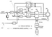
- FIG. 2Ais a basic block diagram illustrating a noise damping system configured in accordance with one embodiment.
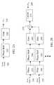
- FIG. 2Bis a basic block diagram illustrating a noise damping system configured in accordance with one embodiment.
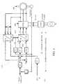
- FIG. 3is a basic block diagram illustrating a noise damping system configured in accordance with one embodiment.
- FIG. 4is a basic block diagram illustrating a torque interface configured in accordance with one embodiment.
- FIG. 5is a block diagram illustrating an embodiment of a direct torque interface.
- FIG. 6is a plot showing a simulated noise signal and the response of the generator, indicated by the correction signal applied to the generator by power electronics, resulting into a well-damped noise signal.
- FIG. 7is a flow chart illustrating the process flow for the noise damping system in accordance with one embodiment.
- gearboxesshall include the various forms of transmissions and drive trains that experience noise and vibration issues.
- the noise reductionis achieved by suppressing the effect of the noise excitation, such as the gear-mesh excitation, by using a noise reduction control circuit for the drive system.
- the noise reduction circuitgenerates a dynamic torque feedback signal with the same frequency as the noise signal but at a different phase, wherein the feedback signal is fed back to the air-gap torque of the system, such as electric motor or generator.
- electric machineshall refer to the various motors and generators that can be coupled to a drive train.
- variable speed drivessuch as variable speed drives or wind turbine drive trains. At some speeds these systems can cause vibrations at the frequency of acoustic resonant points. These small vibration amplitudes in some limited cases can have an environmental impact if the resulting vibration frequency is in the human audible frequency range, especially if the noise levels required by engineering standards are exceeded or close to required standards. At certain speeds of the turbine, there is a drastic noise increase that is based on a complex interaction of the elements of the drive train involving the resonance effects.
- the drive train 10can be a gearbox with associated shafts and coupling as well as other forms of gear assemblies and transmissions that transfer torque.
- the drive train 10is typically coupled to some form of device that accommodates the torque transfer such as a generator 20 in this example. While gear assemblies are used herein for illustrative purposes, there are other forms of transmissions (or torque converters) including hydrostatic transmissions, hydrodynamic transmissions, chain and belt drives, and Cardan couplings.
- a motor(not shown) may be coupled to the drive train.
- One aspectincludes a drive train that is a gearbox and generates noise excitation caused by the meshing gear.
- the sensor 30can be acoustic, mechanical or electrical and includes microphones to process acoustical energy, accelerometers and other devices to extract vibration energy, and surface acoustic wave devices to extract electrical energy.
- the sensor in one examplecan be defined by measurement categories such as force, acceleration, sensitivity, bandwidth, resolution, accuracy, linearity, directionality, environmentally dependency (e.g.: temperature and pressure), size, application, mounting.
- the output(s) from the sensorsis communicated to a control section that interprets the measured sensor signal.
- the vibration frequencycan be predetermined tonal region or frequency that is known to be a concern for the system or it can be a measured frequency.
- the sensorobtains just a frequency measurement and in another embodiment the sensor obtains a noise level and the frequency measurement.
- One aspectincludes a measurement of the frequency and noise level that is then used in a feedback circuit. The level or power of the noise level can be used to determine whether the system requires damping by comparing to a pre-determined limit, wherein the noise reduction would only occur when needed.
- the systemoperates with some measured frequency-response and a self-tuning phase lag.
- the vibration frequencyis obtained from the measurement and only the required phase lag for the damping torque needs to be processed.
- the senor 30is an acoustic sensor, and in one aspect the sensor is a microphone.
- a broadband microphonemay not properly discern the low frequency signals properly and some filtering, such as a lowpass filter or bandpass filter can limit the received frequency range by the microphone. Amplification of the signal is also within the scope and knowledge of the present system.
- filteringsuch as a lowpass filter or bandpass filter can limit the received frequency range by the microphone.
- Amplification of the signalis also within the scope and knowledge of the present system.
- One example employing a microphone for measuring gearbox noiseis described in the paper “ Vibration Analysis of the Windflow Turbine Gearbox ” by Commtest Instruments Ltd.
- a further mechanism for measuringincludes the use of accelerometers that measure structural vibration.
- Another sensor measurement embodimentis via a strain gauge that can sense deformation.
- the sensingis accomplished using surface acoustical wave (SAW) devices, bulk acoustic wave (BAW) devices, and micro-mechanical systems (MEMS) devices.
- SAWsurface acoustical wave
- BAWbulk acoustic wave
- MEMSmicro-mechanical systems
- the sensing section 30is coupled to a damping control circuit 40 .
- the damping circuit 40is typically integrated into either the drive train electronics or the generator electronics, such as with the converter controller.
- the sensor 30is typically proximate or coupled to the drive train 10 , and can transmit the measured signals by wire or wireless techniques.
- the information from the sensor 30is communicated for processing by the control or damping circuit 40 that uses the measured noise signals to generate a phase shifted corrective signal to dampen the noise.
- the sensed signal from the sensor 30can include noise frequency and noise power, frequency only or noise power only, depending upon design criteria. Furthermore, the sensing can be continuous, periodic, or based upon some manual or automatic event. In a general sense, the sensor measures the signal and the control section performs the subsequent processing.
- the output of the damping circuit 40is a dynamic torque signal ( ⁇ T ref ) that is typically coupled to the torque signal of the generator converter electronics 55 .
- ⁇ T refdynamic torque signal
- the torque signal of the converter electronicis modulated by the dynamic torque signal, wherein the modulation frequency of the dynamic torque signal is approximately the same as the excitation source causing the noise amplification problems—but with a different phase.
- a dynamic torque interfacecan process the signal from the damping circuit 40 resulting in a modulated corrective signal that is input to the converter 55 which can then be introduced to the generator 20 .
- the converter or converter controller 55applies the corrective signal to the air-gap torque of the generator 40 .
- a torque signalsuch as a DC signal level, that is modulated by the corrective signal wherein the modulation is at the frequency of the noise signal.
- the damping circuit 40 , torque interface and/or converter 55can be part of the existing converter controller section.
- the dynamic torquehas the same frequency as the one that is responsible for the noise effect but with a different phase and is transmitted to the generator 20 to effectuate a damping of the noise.
- the air-gap torquedampens gearbox noise using a signal modulated by the dynamic torque ( ⁇ T ref ).
- Electrical generatorstypically utilize a rotating magnetic field created by the field winding carried by the generator rotor. As the rotor turns, a torque is produced on the rotor, acting through an air gap that exists between the rotor and the stator, that results from the electromagnetic field interaction with the stator winding. This torque which is also referred to as air gap torque, is proportional to the electrical power produced by the generator at constant rotor angular velocity. The magnetic field interacts with the stator armature winding to produce voltage and current which can then be supplied to a load.
- air gap torqueand various air gap torque calculations in electrical machine processing is known to those skilled in the art.
- the phase shifted noise-damping signal 50 in one embodimentis superimposed or otherwise combined with the air-gap torque of the generator 20 .
- the introduction of the noise-damping signal to the electrical machinecan be accomplished in several manners, some of which are described in U.S. Pat. No. 7,173,399 and Published Patent Application No. U.S. 2006/0244425.
- FIG. 2AThere are several options for processing the dynamic torque signal for dampening the noise signal.
- the noise signal 205is input to a phase shifter 215 that changes the phase of the noise signal.
- the noise signal 205can be from the sensor of FIG. 1 and include at least one of a frequency and/or noise power level.
- the noise signalin one embodiment is a measured noise frequency and noise level and used in a feedback damping circuit to produce the torque signal.
- satisfactory dampingis achieved as long as the feedback signal is phase shifted by a delay of about T/4 for a phase shift of about 90 degrees lagging.
- the phase shift amountcan be in a range of about 0 ⁇ T ⁇ T/2, resulting into 0° ⁇ Phi ⁇ 180° would be appropriate to apply damping behavior to the drive train.
- the corresponding effect of dampingis proportional with sin(Phi), such that more torque is required to achieve the same results with pure adjusted phase shift compared to the more accurate phase shift.
- the processing of the dynamic torqueoperates with some tolerance about the noise frequency.
- the noise signalwas a 70 Hz component and varied by ⁇ 5 Hz
- the feedback circuitwould not be adversey affected.
- a frequency variation of 5°results in a phase shift variation of 6.43° and a gain reduction to 0.99 (sin(83.57°), instead of 1.00 (sin(90°), if system is perfectly adjusted to 90° @ 70 Hz. This is far more robust than most active noise cancellation approaches that have high sensitivity to the noise frequency.
- phase shiftingcan be accomplished in a number of ways including phase shifting circuits and time delay modules.
- phase shiftcan be achieved by digital schemes including software configured hardware such as Field Programmable Gate Arrays (FPGA) or Digital Signal Processors (DSP), Programmable Logic Devices (PLD) and Complex Programmable Logic Devices (CPLD) which can include using memory elements such as look up tables.
- FPGAField Programmable Gate Arrays
- DSPDigital Signal Processors
- PLDProgrammable Logic Devices
- CPLDComplex Programmable Logic Devices
- the robust nature of the feedback circuitpermits a fixed or constant value for the phase shifter instead of a measured value.
- the fixed or constant valuecould be, for example, a predetermined value, a factory value, an intermittent measured value or some combination thereof.
- phase shiftingis in the time domain.
- the 3.57 ms delayis also acceptable for a 65 Hz or 75 Hz noise signal, or the band of 70 Hz ⁇ 5 Hz.
- the phase shifted signalis then amplified by a gain stage 220 such as an amplifier, to boost the dampening signal to a sufficient level to properly cancel the noise or reduce it to an acceptable level.
- the gain stagecan be part of the feedback circuit using some measured or estimated noise level to provide some indication of the level for the damping signal.
- This phase shifted corrective signal (T ref ) 225is then used as an input to the torque interface and converter control system to dampen the noise signal.
- the gain leveldepends on the overall closed loop gain of the system including such features as the noise measurement, effective control loop gain, and mechanical “gain” of shaft.
- the systemuses a sensor to measure the level of the noise/vibration and can determine whether an acceptable level has been met.
- the sound pressure level or the strength of the noise signalcan be measured and the damping only occurs if the noise is above a certain threshold. If the damping effect is not properly mitigated, further iterations and/or amplification of the damping signal can be performed.
- one or more noise signals 240 , 235can be processed to dampen more than a single low frequency noise or vibration signal.
- the noisecan be from two or more frequency signals and require corresponding dampening.
- the damping circuitcomprises filtering of the sensed signal 230 , 235 by one or more filters 255 , 280 to focus on the vibration frequency of interest.
- a bandpass filtercan be used to isolate a frequency band within a region of the low frequency signal.
- the noise signal 230 , 235can be optionally filtered such as by a bandpass filter or low pass filter to reject interfering signals depending upon certain factors such as the desired signal of interest, the strength of the signals and the noise or interference.
- phase shift sections 260 , 285can then shift the one or more filtered noise signals to generate a phase shifted corrective noise signal.
- satisfactory dampingis achieved as long as the feedback signal is phase shifted by a delay of about 90 degrees lagging or T/4, however the phase shift can be in the range of about about 0 ⁇ T ⁇ T/2.
- the phase shifted corrective noise signalcan then be optionally amplified by one or more gain stages 265 , 290 .
- the resulting one or more phase shifted noise cancellation signalscan be summed by a summer 270 and can be further processed by an optional limiter 275 .
- the limiter 275may be used for safety reasons to avoid a resulting signal that might harm personnel or equipment.
- the noise damping phase shifted signal (T ref ) 295is then used as an input to the control system to address the noise signal.
- Structure-borne noise from wind systemstends to be force related radiated noise from wind turbine vibration structures such as blades, tower and nacelle that can be excited by dynamic forces created by drive train power conversion components such as the generator and gearbox.
- the generator and power electronicsare used to actively damp this tonality effect by generating a torque ripple at a noise frequency and with a different phase to counteract the potential noise issue.
- one embodiment of the systemworks to effectively damp the noise when there is a certain noise level. The damping is accomplished by a torque signal acting on the shaft that is modulated at the same frequency as the excitation source causing the noise amplification with a different phase. For example, damp noise amplification caused by gear mesh excitation at various speeds.
- An aspectis to avoid resonance peaks by introducing the damping torque via the generator winding (high speed shaft), even though the noise itself may be caused at the low speed shaft.
- Wind turbines with full power conversionhave an existing converter that can be used to apply the corrective torque signal and involve only minor retrofit.
- the low power damping signalcorrects the noise issue without undue power consumption.
- one aspectrelates to a wind converter 300 , wherein the noise reduction system suppresses noise effects generated by the drive train of the wind turbine.
- the wind converter 300typically has a number of blades 310 that rotate due to the force of the wind.
- the rotating blades 310cause the low speed shaft 315 to rotate at a relatively low speed but with great torque.
- a gearbox 320is coupled to the low speed shaft 315 and transfers the rotational energy to a high-speed shaft 325 .
- the drive train in this exampleincludes the low speed shaft 315 , the gearbox 320 , and the high-speed shaft 325 .
- the high-speed shaft 325is coupled to a generator 330 that generates the power that can be conditioned and electrically coupled to some electrical grid (not shown).
- One or more sensors 350may be positioned about the drive train at locations where the audible noise may be problematic. Locations for sensing noise and vibration could be at the gearbox torque arms, the gearbox housing, the rotor shaft (low-speed shaft), the main bearing carrying the rotor shaft, the base frame of the nacelle, or the tower. Multiple sensor types and locations may be useful when different natural frequencies are present along the drive train elements such as the gearbox 320 . For example, vibration or acoustic noise signals generated proximate the drive train, such as by the torque arms, can be sensed by the sensors 350 to detect the frequency and/or power of the noise signals.
- the damping controller 360generates an air-gap torque modulated signal that is applied to the controller 340 of the generator 330 thereby interacting with the high-speed shaft of the drive train in order to suppress torque components resulting at the low speed shaft of the drive train, which are excited by the gear meshing.
- Generators 330are ideally suited to excite or dampen alternating torque components by means of converter control, and the corrective noise signal can be thus introduced into the generator electronics.
- the torque signalaccording to one embodiment is introduced to the generator electronics by adding the analog or digital correction signal to a given torque reference signal interface, wherein the torque signal is part of the normal current/speed control loop.
- damping controller 360is integrated with the existing generator controller 340 such that the sensor measurements are communicated to the integrated converter/damping controller.
- the air-gap torque frequencycorresponds to the noise frequency but having a different phase.
- the total phase shiftcorresponds to about T/4 in order to achieve an electronically adjustable damping of the torque components exciting the noise.
- the dynamic torque phase-shifted corrective signalcan be superimposed to the air-gap torque signal of the generator.
- the phase shifted modulated damping signal 440 ⁇ T refis an input to current controller 450 .
- the current controller 450has a current reference 415 used by the current controller 450 to establish the proper operating conditions of the system.
- the damping signal 440is a modulated signal and is combined with the current reference 415 .
- the current controller 450controls the torque building current such that the modulated output signal 475 is an input to the modulator and converter 490 via a coordinate transformation.
- the converterapplies the modified reference signal 475 , which has the phase shifted noise damping signal component 440 , to the generator.
- FIG. 5is a further embodiment of a system for introducing the damping signal and reducing system noise is shown.
- the direct torque controller 500is coupled to the converter 585 that is coupled to the generator 590 .
- a torque reference 505that provides an indication of the torque of the generator.
- the torque reference 505can be based on estimates or measurements.
- a speed reference 510with is an input to a proportional-integral-derivative controller (PID controller).
- PID controllerproportional-integral-derivative controller
- the PIDis used to correct errors between the speed reference 510 and the actual speed 512 .
- the actual speed 512can be taken from sensors and may also come from an adaptive model (not shown).
- the torque reference 505is an input to a torque reference controller 525 .
- the torque reference controller 525also uses the speed output from the PID to generate the torque command signal that is an input to the torque/flux comparator 540 .
- the torque comparatorcompares an internal torque reference signal to an actual torque signal.
- the torque signal from the torque reference controller 525is modified with the modulated phase shifted noise-damping signal 550 .
- the damping signal 550is added to the output of the torque/flux comparator 540 .
- the output from the torque/flux comparatorcan include a torque status, torque control signals, and flux status.
- the optimum pulse selector 575 of the processor 570uses these signals to generate the optimal direct torque control signal that is then applied to the converter 585 .
- the output of the comparator 540is an input to a processing unit that performs the processing functions.
- the processing unitis broadly defined as any computing device or processor able to perform some computing.
- the torque or noise signal 610excites the structure to radiate the audible noise.
- torque and audible noisecan be seen as related aspects.
- the torque associated with a drive traintypically employs a counter-force to hold the system in balance, and for gearboxes, this counter-force is typically via the torque arm.
- the modulated damping signal 620is applied to the air-gap torque and as shown, the resulting noise response 610 from the structure (or transmission) is greatly reduced.
- the noise signalcan be a measurement from sensor technologies as detailed herein and may not necessarily be a torque measurement.
- the generator with the feedback signalcan be understood as a torque correction signal that is an input to the generator electronics that is combined with the torque reference signal.
- FIG. 7is a flow chart illustrating one aspect of a damping system showing the closed loop of the damping circuit processed in real time.
- the processcommences in one embodiment by processing a noise signal 705 .
- the noise signalcan be measured, intermittently measured or estimated.
- the acoustic or vibration signalis measured by sensors, wherein the sensor measurements can be taken at the torque arms of the drive train.
- the noise signalmay be filtered and amplified to obtain an improved noise signal in certain implementations.
- the noise signalis then phase-shifted 710 .
- One manner to shift the phaseis by a time delay, and according to one embodiment the phase shifter shifts the time delay about T/4 or lagging 90 degrees.
- the phase shiftershifts the time delay about T/4 or lagging 90 degrees.
- There are other examplessuch as a phase shift of about 90+360 degrees which is in connection with a helicopter drive that has a generator coupled to the drive train and with corresponding power electronics controlling the generator.
- the phase-shifted damping signalis then modulated to create a modulated torque signal 715 .
- the modulationcan be a sine wave with the frequency of the sine wave approximately the frequency of the noise.
- the modulated torque signalis applied in one embodiment to the control system of a converter 720 .
- An optional stepis to periodically (or upon some event) measure the noise signal and provide a corrective damping signal if the measured noise signal was above a certain threshold 725 .
- the thresholdwould depend upon certain conditions with the overall result being to reduce the environmental noise to a safe level. Multiple iterations might be undertaken until a satisfactory damping was accomplished.
- the noise reduction system for the wind turbine gearboxis a low cost solution using standard sensing equipment and electronics.
- Such a systemcan be integrated as a feature of new products or as a retrofit for wind turbines with “noisy” gearboxes or in neighborhoods where the noise level must be kept as low as possible.
- the systemcan also be applied to other drive train applications with noise issues, especially when gearboxes are involved.
- one embodimentprovides for applying the electronic silencer or noise reduction system without any apriori knowledge as to the cause of the noise signal.
- the actual noise sourceis difficult to extract, it does not matter what is causing the elevated audible noise, such as a 70 Hz component. All that is required is some knowledge of the acoustic or vibration signal.
- the noise signalin one aspect is measured such as employing a sensor at the torque arms.
- the noise signalmay be processed to get a better defined noise frequency component.
- the signalcan be amplified and/or filtered prior to being phase shifted.
- the phase shifted noise frequency signalis then used to modulate the generator air-gap torque by means of the installed voltage-source converter.
- the voltage-source converterin one example and typically has a torque controller.
- the current wind turbine systemsare a practical and efficient renewable energy source. Improvements to the system have increased efficiencies and have led to increased demands. In addition, the location of the wind turbine sites is getting closer to residences through windfarms or from homeowner or company site installations. In order to maintain public support for the wind turbines, the wind industry addresses any noise issues that may arise and have adequate remedies.
- gearboxes in relation to wind turbinesare relatively complex as the aerodynamic fluctuations cause large torque changes. As the wind turbines are increasing in size, the gearboxes are becoming larger and more complex. The larger gearboxes may be more prone to the mechanical noise generation issues.
- Such gearboxesinclude the multiple generator drive trains that can provide multiple power paths via multiple gear sets.
- the noise reduction system detailed hereinallows a reduction of noise in the drive trains such as gearboxes.
- the noise reductionis achieved by increasing the damping behavior of the structure at a frequency related to the noise excitation, such as gear-mesh excitation, by means of the noise reduction circuit for the electrical drive system.
- the noise reduction circuitgenerates a dynamic torque which can be superimposed to the air-gap torque of the electric generator, wherein the dynamic torque has the same frequency as the noise signal (for example, in the range 40-70 Hz), but a different phase.
- Another embodimentrelates to implementing the present silencer system for helicopters.
- the main rotor system of a helicopterincludes rotor blades mounted on a vertical shaft that project from the gearbox.
- the gearboxcomprises a number of gears that reduce the rotational speed of the helicopter's engine to the much slower rotational speed of the main rotor blades.
- the noise reduction systems detailed hereincan be implemented with the helicopter gearbox to shift the phase of the noise frequency such as using a phase shift of 90+360 degrees.
- a benefit of the noise reduction system detailed hereinis that it reduces the noise issues with minimal power consumption. Another feature is that it is implementable as a retrofit to existing systems such that only those systems requiring lower noise requirements would require a retrofit or factory installation.
- the present systemis not restricted to a single noise source. Rather, one embodiment of the present system does not care about the sources of the noise and uses a measured acoustic or vibration signal to create a cancelling noise signal that is phase shifted, and applied to the air-gap torque of the generator. There can be multiple noise outputs from the drive train and one or more corrective damping signals.
- noise reduction systemherein is that it can co-exist and operate in conjunction with other active and passive noise reduction implementations. It seeks to reduce noise that already exists on the system. It can target a particular tonal frequency band that would otherwise exist.
Landscapes
- Engineering & Computer Science (AREA)
- General Engineering & Computer Science (AREA)
- Mechanical Engineering (AREA)
- Physics & Mathematics (AREA)
- General Physics & Mathematics (AREA)
- Automation & Control Theory (AREA)
- Measurement Of Mechanical Vibrations Or Ultrasonic Waves (AREA)
- Wind Motors (AREA)
- Control Of Eletrric Generators (AREA)
- Vibration Prevention Devices (AREA)
Abstract
Description
Claims (21)
Applications Claiming Priority (3)
| Application Number | Priority Date | Filing Date | Title |
|---|---|---|---|
| EP07122882.9 | 2007-12-11 | ||
| EP07122882 | 2007-12-11 | ||
| EP07122882.9AEP2071213B1 (en) | 2007-12-11 | 2007-12-11 | Gearbox noise reduction by electrical drive control |
Publications (2)
| Publication Number | Publication Date |
|---|---|
| US20090149999A1 US20090149999A1 (en) | 2009-06-11 |
| US8532828B2true US8532828B2 (en) | 2013-09-10 |
Family
ID=39272714
Family Applications (1)
| Application Number | Title | Priority Date | Filing Date |
|---|---|---|---|
| US12/266,757Active2030-02-02US8532828B2 (en) | 2007-12-11 | 2008-11-07 | Gearbox noise reduction by electrical drive control |
Country Status (5)
| Country | Link |
|---|---|
| US (1) | US8532828B2 (en) |
| EP (1) | EP2071213B1 (en) |
| CN (1) | CN101493142B (en) |
| DK (1) | DK2071213T3 (en) |
| ES (1) | ES2528185T3 (en) |
Cited By (16)
| Publication number | Priority date | Publication date | Assignee | Title |
|---|---|---|---|---|
| US20120017856A1 (en)* | 2010-07-22 | 2012-01-26 | Robert Bosch Gmbh | Systems and methods for avoiding resonances excited by rotating components |
| US20130260692A1 (en)* | 2012-03-29 | 2013-10-03 | Bose Corporation | Automobile communication system |
| US20170302204A1 (en)* | 2016-04-14 | 2017-10-19 | General Electric Company | Wind Converter Control for Weak Grid |
| US20170342920A1 (en)* | 2015-01-12 | 2017-11-30 | Tula Technology, Inc. | Engine torque smoothing |
| US9995277B2 (en) | 2014-07-31 | 2018-06-12 | General Electric Company | System and method for controlling the operation of wind turbines |
| US10040446B2 (en)* | 2016-10-24 | 2018-08-07 | International Business Machines Corporation | Reducing noise generated by a motorized device |
| US10221786B2 (en) | 2015-01-12 | 2019-03-05 | Tula Technology, Inc. | Noise, vibration and harshness reduction in a skip fire engine control system |
| US10344692B2 (en) | 2015-01-12 | 2019-07-09 | Tula Technology, Inc. | Adaptive torque mitigation by micro-hybrid system |
| US10386869B2 (en)* | 2013-07-30 | 2019-08-20 | Trane International Inc. | Automated system to determine variable frequency drive skip frequency bands for vibration control |
| US10400744B2 (en) | 2016-04-28 | 2019-09-03 | General Electric Company | Wind turbine blade with noise reducing micro boundary layer energizers |
| US10436133B2 (en) | 2015-01-12 | 2019-10-08 | Tula Technology, Inc. | Engine torque smoothing |
| US10450863B2 (en) | 2016-06-02 | 2019-10-22 | General Electric Company | Turbine engine shaft torque sensing |
| US10578037B2 (en) | 2015-01-12 | 2020-03-03 | Tula Technology, Inc. | Adaptive torque mitigation by micro-hybrid system |
| US10788394B2 (en) | 2017-09-12 | 2020-09-29 | General Electric Company | Gearbox sensor arrangement |
| US10954877B2 (en) | 2017-03-13 | 2021-03-23 | Tula Technology, Inc. | Adaptive torque mitigation by micro-hybrid system |
| US11555461B2 (en) | 2020-10-20 | 2023-01-17 | Tula Technology, Inc. | Noise, vibration and harshness reduction in a skip fire engine control system |
Families Citing this family (30)
| Publication number | Priority date | Publication date | Assignee | Title |
|---|---|---|---|---|
| DE102008047476B4 (en)* | 2008-09-17 | 2020-02-06 | Bayerische Motoren Werke Aktiengesellschaft | Control device for compensating alternating torques of an internal combustion engine |
| RU2478802C2 (en)* | 2008-10-30 | 2013-04-10 | Вольво Ластвагнар Аб | Automatic control method of turbo-compound transmission ability to transfer torque moment |
| IT1399115B1 (en)* | 2010-04-01 | 2013-04-05 | Nuova Pignone S R L | SYSTEM AND METHOD OF DAMPING THE TORSIONAL WAY BASED ON A RECTIFIER |
| US8606410B2 (en)* | 2010-06-29 | 2013-12-10 | Headway Technologies, Inc. | Drive method for starting and operating a resonant scanning MEMS device at its resonant frequency |
| EP2463517B1 (en) | 2010-12-08 | 2014-06-25 | Siemens Aktiengesellschaft | Method and control system for reducing vibrations of a wind turbine |
| CN103161931B (en)* | 2011-12-14 | 2016-02-17 | 周登荣 | The controlling method of Feng Ta power station gearbox of generator |
| DK2651028T3 (en) | 2012-04-13 | 2019-05-13 | Siemens Gamesa Renewable Energy As | Assessment of toothing |
| US8933576B2 (en) | 2012-05-02 | 2015-01-13 | United Technologies Corporation | Hybrid friction wheel gearbox drivetrain for wind turbine applications |
| US9091250B2 (en) | 2012-05-02 | 2015-07-28 | United Technologies Corporation | Ultra high efficiency low friction drive chain for wind turbine applications |
| US8924109B2 (en)* | 2012-06-07 | 2014-12-30 | GM Global Technology Operations LLC | Vibration detection and mitigation in a vehicle |
| US8598725B1 (en) | 2012-06-11 | 2013-12-03 | United Technologies Corporation | Utilizing flux controllable PM electric machines for wind turbine applications |
| CN102982798B (en)* | 2012-12-07 | 2015-07-15 | 奇瑞汽车股份有限公司 | Noise reduction system of generator |
| US9200943B2 (en)* | 2013-07-17 | 2015-12-01 | GM Global Technology Operations LLC | Acoustic sensing system for a motor vehicle |
| US9683553B2 (en) | 2013-09-06 | 2017-06-20 | General Electric Company | System and method for monitoring wind turbine loading |
| DE102013219976A1 (en)* | 2013-10-02 | 2015-04-02 | Zf Friedrichshafen Ag | Method for damping powertrain vibrations in motor vehicles |
| US9890575B2 (en) | 2013-12-09 | 2018-02-13 | Viking Access Systems, Llc | Movable barrier operator with removable power supply module |
| US9708845B2 (en)* | 2014-03-05 | 2017-07-18 | Viking Access System, Llc. | Movable barrier operator employing MEMS-based inertial measuring unit for gathering barrier parameter data |
| DE102014222977A1 (en)* | 2014-11-11 | 2016-05-12 | Robert Bosch Gmbh | Apparatus and method for reducing gear noise |
| WO2016127147A1 (en) | 2015-02-06 | 2016-08-11 | Regents Of University Of Minnesota | Dual purpose no voltage winding design for bearingless ac homopolar and consequent pole motors and an ac homopolar flywheel energy storage system |
| DE102015008937A1 (en) | 2015-07-10 | 2017-01-12 | Daimler Ag | Method for operating a fuel cell system |
| DE102016219981A1 (en)* | 2016-10-13 | 2018-04-19 | Audi Ag | Method for adjusting an electric actuator |
| ES3014981T3 (en)* | 2018-11-16 | 2025-04-28 | Vestas Wind Sys As | Wind turbine noise masking |
| CN110427721B (en)* | 2019-08-09 | 2022-11-04 | 西北工业大学 | Topological optimization design method for low-noise gearbox structure |
| FR3106385B1 (en) | 2020-01-17 | 2022-01-14 | Psa Automobiles Sa | METHOD FOR CALIBRATION OF A GEAR CHANGE LAW AS A FUNCTION OF THE INDIVIDUAL MODES OF THE TRACTION CHAIN |
| CN113595457B (en)* | 2021-08-05 | 2024-03-22 | 浙江大学 | Wind turbine and its control system |
| CN113726236B (en)* | 2021-08-11 | 2024-06-28 | 上海电气风电集团股份有限公司 | Wind turbine generator set and its control system |
| CN114368268B (en)* | 2021-08-24 | 2023-11-03 | 华为数字能源技术有限公司 | A powertrain, noise suppression method and electric vehicle |
| US20250154931A1 (en)* | 2021-12-21 | 2025-05-15 | Vestas Wind Systems A/S | A method for reducing noise from wind turbine gearbox vibrations |
| WO2023155960A1 (en)* | 2022-02-17 | 2023-08-24 | Vestas Wind Systems A/S | Method of controlling tonal noise from a wind turbine |
| CN119156494A (en)* | 2022-05-03 | 2024-12-17 | 维斯塔斯风力系统集团公司 | Method of handling gearbox vibrations in a wind turbine |
Citations (88)
| Publication number | Priority date | Publication date | Assignee | Title |
|---|---|---|---|---|
| US3887853A (en)* | 1973-12-14 | 1975-06-03 | Eaton Corp | Stabilizing system for an inverter-driven induction motor |
| US4057714A (en)* | 1975-09-30 | 1977-11-08 | Kraftwerk Union Aktiengesellschaft | Durability or service-life monitoring device for a turbogenerator shaft |
| US4384246A (en)* | 1981-01-30 | 1983-05-17 | General Electric Company | Series-thyristor subsynchronous damper for power generators |
| US4506380A (en)* | 1982-07-07 | 1985-03-19 | Nissan Motor Company, Limited | Method and apparatus for controlling the sound field in a vehicle cabin or the like |
| US4567975A (en)* | 1984-02-17 | 1986-02-04 | Warner Electric Brake & Clutch Co. | Apparatus and method for controlling the engagement of a gap-type electromagnetic coupling and for alleviating engagement noise |
| US4695736A (en)* | 1985-11-18 | 1987-09-22 | United Technologies Corporation | Variable speed wind turbine |
| US4982825A (en)* | 1989-05-11 | 1991-01-08 | Sepal | Torque and air gap adjustment mechanism for spring engaged brake or clutch |
| US5049797A (en)* | 1990-07-02 | 1991-09-17 | Utah State University Foundation | Device and method for control of flexible link robot manipulators |
| US5112019A (en)* | 1991-02-04 | 1992-05-12 | Storz Instrument Company | Motorized IV pole assembly |
| US5117926A (en)* | 1990-02-20 | 1992-06-02 | Shell Oil Company | Method and system for controlling vibrations in borehole equipment |
| US5126641A (en)* | 1991-03-08 | 1992-06-30 | Westinghouse Electric Corp. | Bidirectional variable reluctance actuator and system for active attenuation of vibration and structure borne noise utilizing same |
| US5172717A (en)* | 1989-12-27 | 1992-12-22 | Otis Engineering Corporation | Well control system |
| US5310137A (en)* | 1992-04-16 | 1994-05-10 | United Technologies Corporation | Helicopter active noise control system |
| US5313407A (en)* | 1992-06-03 | 1994-05-17 | Ford Motor Company | Integrated active vibration cancellation and machine diagnostic system |
| US5398904A (en)* | 1993-03-31 | 1995-03-21 | Itt Corporation | Gear reducer |
| US5485523A (en)* | 1992-03-17 | 1996-01-16 | Fuji Jukogyo Kabushiki Kaisha | Active noise reduction system for automobile compartment |
| US5497313A (en)* | 1992-12-30 | 1996-03-05 | L'unite Hermetique | Switching method and apparatus for increasing efficiency of an inductive load and switching means supplying the load |
| EP0774411A2 (en) | 1995-11-18 | 1997-05-21 | Gkn Westland Helicopters Limited | Helicopter and method for reducing vibration of a helicopter fuselage |
| US5646350A (en)* | 1996-01-23 | 1997-07-08 | Computational Systems Inc. | Monitoring slow speed machinery using integrator and selective correction of frequency spectrum |
| US5677958A (en)* | 1993-07-07 | 1997-10-14 | Leistritz Ag & Co Abgastechnik | Active sound damper |
| US5711736A (en)* | 1994-06-03 | 1998-01-27 | Sony Corporation | Motor apparatus with reduction gear |
| WO1998030813A1 (en) | 1997-01-07 | 1998-07-16 | Gte Internetworking Incorporated | Active cancellation of noise at gear mesh frequencies for a gear assembly underload |
| US5802184A (en)* | 1996-08-15 | 1998-09-01 | Lord Corporation | Active noise and vibration control system |
| US5841254A (en)* | 1997-07-09 | 1998-11-24 | General Electric Company | Torque maximization and vibration control for AC locomotives |
| US5894220A (en)* | 1996-02-12 | 1999-04-13 | University Of Maryland | Apparatus for microscopic imaging of electrical and magnetic properties of room-temperature objects |
| US5961413A (en)* | 1997-02-27 | 1999-10-05 | Poclain Hydraulics | Hydraulic drive for construction machine |
| US6028402A (en)* | 1999-01-25 | 2000-02-22 | General Electric Company | Automatic rail characterization for adhesion system evaluation for AC locomotives |
| US6078673A (en)* | 1997-10-03 | 2000-06-20 | Hood Technology Corporation | Apparatus and method for active control of sound transmission through aircraft fuselage walls |
| US6091177A (en)* | 1999-03-22 | 2000-07-18 | Siemens Westinghouse Power Corporation | Spring mounting for an electric generator |
| US6105900A (en)* | 1997-12-23 | 2000-08-22 | Sikorsky Aircraft Corporation | Active noise control system for a helicopter gearbox mount |
| US6148784A (en)* | 1995-08-31 | 2000-11-21 | Isad Electronic Systems Gmbh & Co. Kg | Drive systems, especially for a motor vehicle, and method of operating same |
| US6163121A (en)* | 1999-01-29 | 2000-12-19 | General Electric Company | Torque maximization and vibration control for AC locomotives |
| US6308140B1 (en)* | 1996-05-20 | 2001-10-23 | Crane Nuclear, Inc. | Motor condition and performance analyzer |
| WO2002008055A1 (en) | 2000-07-21 | 2002-01-31 | Sikorsky Aircraft Corporation | System for active noise reduction |
| US6348751B1 (en)* | 1997-12-12 | 2002-02-19 | New Generation Motors Corporation | Electric motor with active hysteresis-based control of winding currents and/or having an efficient stator winding arrangement and/or adjustable air gap |
| US6405701B1 (en)* | 1995-08-31 | 2002-06-18 | Isad Electronic Systems Gmbh & Co. Kg | System for actively reducing rotational nonuniformity of a shaft, in particular, the drive shaft of an internal combustion engine, and method for this |
| US6439831B1 (en)* | 2000-04-20 | 2002-08-27 | Wayne Ernest Conrad | Method and apparatus for improving efficiency and/or altering acoustic signature of surface and submerged vessels |
| US20020198690A1 (en)* | 1996-02-06 | 2002-12-26 | The Regents Of The University Of California | System and method for characterizing, synthesizing, and/or canceling out acoustic signals from inanimate sound sources |
| US20030015359A1 (en)* | 2001-07-04 | 2003-01-23 | The Electric Motor Company Limited | Power generation means for a vehicle |
| US20030030338A1 (en)* | 2001-03-15 | 2003-02-13 | Eric Beishline | Belt driven electro-mechanical actuator |
| US20030074120A1 (en)* | 2001-10-11 | 2003-04-17 | Kleinau Julie A. | Method and apparatus for motor velocity measurement compensation in electric power steering damping |
| US20030093231A1 (en) | 2001-11-12 | 2003-05-15 | O-Jun Kwon | Method and apparatus for reducing engine chain vibration |
| US20030112980A1 (en)* | 2001-12-17 | 2003-06-19 | Siemens Vdo Automotive, Inc. | Digital filter modeling for active noise cancellation |
| US6751534B2 (en)* | 2000-12-21 | 2004-06-15 | Ford Global Technologies, Llc | System and method for providing feedback to a driver of a hybrid vehicle |
| US20040176213A1 (en)* | 2003-03-06 | 2004-09-09 | Luk Lamellen Und Kupplungsbau Beteiligungs Kg | Method for controlling a clutch |
| US20040237683A1 (en)* | 2003-05-31 | 2004-12-02 | Mikhail Amir S. | Distributed power train (DGD) with multiple power paths |
| US6865466B2 (en)* | 2000-04-27 | 2005-03-08 | American Axle & Manufacturing, Inc. | Active vibration cancellation of gear mesh vibration |
| US20050077793A1 (en)* | 2001-10-05 | 2005-04-14 | Seamus Garvey | Electrical machine having capability to generate lateral forces |
| US20050077800A1 (en)* | 2002-03-01 | 2005-04-14 | Tno | Electromechanical converter |
| WO2006007891A1 (en) | 2004-04-30 | 2006-01-26 | MAX-PLANCK-Gesellschaft zur Förderung der Wissenschaften e.V. | Device and method for exciting a torsional oscillation in a rotating drive train |
| US7013859B2 (en)* | 2001-11-15 | 2006-03-21 | Karl-Heinz Linnig Gmbh & Co. Kg | Device for damping torsional vibrations |
| US20060066110A1 (en)* | 2004-09-27 | 2006-03-30 | General Electric Company | Electrical machine with double-sided lamination stack |
| US20060066111A1 (en) | 2004-09-30 | 2006-03-30 | Shashikanth Suryanarayanan | Vibration damping system and method for variable speed wind turbines |
| US20060087270A1 (en)* | 2004-10-25 | 2006-04-27 | Jaroslav Spicka | Method of controlling an electric motor with oscillating output shaft, particularly for automobile wiper systems, and the arrangement of that electric motor |
| US20060118309A1 (en)* | 2002-07-23 | 2006-06-08 | Philip Head | Seabed installation apparatus |
| US20060197394A1 (en)* | 2005-01-31 | 2006-09-07 | Applegate Rodney W | Apparatus and system for driving a fan using a linear induction motor |
| US7106867B2 (en)* | 2001-05-08 | 2006-09-12 | Siemens Vdo Automotive Inc. | Active noise cancellation for a vehicle induction system having selectable engine noise profile |
| DE102005034678A1 (en) | 2005-04-13 | 2006-10-19 | Ford Global Technologies, LLC, Dearborn | System and method for controlling the moment of inertia reaction |
| US20060244425A1 (en) | 2003-06-13 | 2006-11-02 | Christof Sihler | Method and damping device for damping a torsional vibration in a rotating drivetrain |
| US7154193B2 (en)* | 2004-09-27 | 2006-12-26 | General Electric Company | Electrical machine with double-sided stator |
| US7154191B2 (en)* | 2004-06-30 | 2006-12-26 | General Electric Company | Electrical machine with double-sided rotor |
| US7173399B2 (en)* | 2005-04-19 | 2007-02-06 | General Electric Company | Integrated torsional mode damping system and method |
| US7180204B2 (en) | 2005-01-07 | 2007-02-20 | General Electric Company | Method and apparatus for wind turbine air gap control |
| US20070235247A1 (en)* | 2006-04-07 | 2007-10-11 | Nsk Ltd., | Electric power steering device |
| US7285926B2 (en)* | 2005-06-30 | 2007-10-23 | General Electric Company | System and method for locomotive adhesion control |
| US7370720B2 (en)* | 2001-12-28 | 2008-05-13 | Sunstar Giken Kabushiki Kaisha | Electromotive power assisted bicycle |
| US7423411B2 (en)* | 2006-05-05 | 2008-09-09 | General Electric Company | Resistive torsional mode damping system and method |
| US20080284575A1 (en)* | 1995-06-07 | 2008-11-20 | Automotive Technologies International, Inc. | Vehicle Diagnostic Techniques |
| US7464620B2 (en)* | 2004-11-11 | 2008-12-16 | Schukraoof North America | Actuator |
| US20090025488A1 (en)* | 2007-07-27 | 2009-01-29 | General Electric Company | Method and system for non-contact sensing of the torque of a shaft |
| US20090048747A1 (en)* | 2005-11-15 | 2009-02-19 | Stridsberg Powertrain Ab | Hybrid Vehicle With Soft Shafts |
| US20090079191A1 (en)* | 2007-09-26 | 2009-03-26 | General Electric Company | Electric power generation with magnetically geared machine |
| US20090110554A1 (en)* | 2004-05-03 | 2009-04-30 | Wind Energy Group, Inc. | Wind Turbine for Generating Electricity |
| US7542575B2 (en)* | 1998-04-08 | 2009-06-02 | Donnelly Corp. | Digital sound processing system for a vehicle |
| US7548008B2 (en)* | 2004-09-27 | 2009-06-16 | General Electric Company | Electrical machine with double-sided lamination stack |
| US20090232635A1 (en)* | 2008-03-12 | 2009-09-17 | General Electric Company | Independent sensing system for wind turbines |
| US7640808B2 (en)* | 2002-07-31 | 2010-01-05 | Saint-Gobain Glass France | Strip with acoustic damping properties |
| US7692322B2 (en)* | 2004-02-27 | 2010-04-06 | Mitsubishi Heavy Industries, Ltd. | Wind turbine generator, active damping method thereof, and windmill tower |
| US7692357B2 (en)* | 2004-12-16 | 2010-04-06 | General Electric Company | Electrical machines and assemblies including a yokeless stator with modular lamination stacks |
| US20100113164A1 (en)* | 2006-06-09 | 2010-05-06 | Sgf Suddeutsche Gelenkscheibenfabrik Gmbh & Co., Kg | Torque transmission device for the low vibration transmission of torque via at least one shaft |
| US7839049B2 (en)* | 2007-11-29 | 2010-11-23 | General Electric Company | Stator and stator tooth modules for electrical machines |
| US7839048B2 (en)* | 2004-09-27 | 2010-11-23 | General Electric Company | Electrical machine with double-sided stator |
| US7891461B2 (en)* | 2007-10-25 | 2011-02-22 | Honda Motor Co., Ltd. | Motor rotation angle detection device |
| US20110049902A1 (en)* | 2009-08-28 | 2011-03-03 | Fred Noah Miekka | Air cooled brushless wind alternator |
| US20110170701A1 (en)* | 2008-09-18 | 2011-07-14 | Honda Motor Co., Ltd | Active noise control device |
| US7992662B2 (en)* | 2006-01-18 | 2011-08-09 | General Electric Company | Vehicle and method of assembling same |
| US20120130580A1 (en)* | 2010-05-26 | 2012-05-24 | Asako Omote | Artificial engine sound control unit, approaching vehicle audible system, and electric vehicle having them |
| US8194873B2 (en)* | 2006-06-26 | 2012-06-05 | Davis Pan | Active noise reduction adaptive filter leakage adjusting |
- 2007
- 2007-12-11ESES07122882.9Tpatent/ES2528185T3/enactiveActive
- 2007-12-11DKDK07122882.9Tpatent/DK2071213T3/enactive
- 2007-12-11EPEP07122882.9Apatent/EP2071213B1/enactiveActive
- 2008
- 2008-11-07USUS12/266,757patent/US8532828B2/enactiveActive
- 2008-12-11CNCN2008101837130Apatent/CN101493142B/enactiveActive
Patent Citations (98)
| Publication number | Priority date | Publication date | Assignee | Title |
|---|---|---|---|---|
| US3887853A (en)* | 1973-12-14 | 1975-06-03 | Eaton Corp | Stabilizing system for an inverter-driven induction motor |
| US4057714A (en)* | 1975-09-30 | 1977-11-08 | Kraftwerk Union Aktiengesellschaft | Durability or service-life monitoring device for a turbogenerator shaft |
| US4384246A (en)* | 1981-01-30 | 1983-05-17 | General Electric Company | Series-thyristor subsynchronous damper for power generators |
| US4506380A (en)* | 1982-07-07 | 1985-03-19 | Nissan Motor Company, Limited | Method and apparatus for controlling the sound field in a vehicle cabin or the like |
| US4567975A (en)* | 1984-02-17 | 1986-02-04 | Warner Electric Brake & Clutch Co. | Apparatus and method for controlling the engagement of a gap-type electromagnetic coupling and for alleviating engagement noise |
| US4695736A (en)* | 1985-11-18 | 1987-09-22 | United Technologies Corporation | Variable speed wind turbine |
| US4982825A (en)* | 1989-05-11 | 1991-01-08 | Sepal | Torque and air gap adjustment mechanism for spring engaged brake or clutch |
| US5172717A (en)* | 1989-12-27 | 1992-12-22 | Otis Engineering Corporation | Well control system |
| US5117926A (en)* | 1990-02-20 | 1992-06-02 | Shell Oil Company | Method and system for controlling vibrations in borehole equipment |
| US5049797A (en)* | 1990-07-02 | 1991-09-17 | Utah State University Foundation | Device and method for control of flexible link robot manipulators |
| US5112019A (en)* | 1991-02-04 | 1992-05-12 | Storz Instrument Company | Motorized IV pole assembly |
| US5126641A (en)* | 1991-03-08 | 1992-06-30 | Westinghouse Electric Corp. | Bidirectional variable reluctance actuator and system for active attenuation of vibration and structure borne noise utilizing same |
| US5485523A (en)* | 1992-03-17 | 1996-01-16 | Fuji Jukogyo Kabushiki Kaisha | Active noise reduction system for automobile compartment |
| US5310137A (en)* | 1992-04-16 | 1994-05-10 | United Technologies Corporation | Helicopter active noise control system |
| US5313407A (en)* | 1992-06-03 | 1994-05-17 | Ford Motor Company | Integrated active vibration cancellation and machine diagnostic system |
| US5497313A (en)* | 1992-12-30 | 1996-03-05 | L'unite Hermetique | Switching method and apparatus for increasing efficiency of an inductive load and switching means supplying the load |
| US5398904A (en)* | 1993-03-31 | 1995-03-21 | Itt Corporation | Gear reducer |
| US5677958A (en)* | 1993-07-07 | 1997-10-14 | Leistritz Ag & Co Abgastechnik | Active sound damper |
| US5711736A (en)* | 1994-06-03 | 1998-01-27 | Sony Corporation | Motor apparatus with reduction gear |
| US20080284575A1 (en)* | 1995-06-07 | 2008-11-20 | Automotive Technologies International, Inc. | Vehicle Diagnostic Techniques |
| US6148784A (en)* | 1995-08-31 | 2000-11-21 | Isad Electronic Systems Gmbh & Co. Kg | Drive systems, especially for a motor vehicle, and method of operating same |
| US6405701B1 (en)* | 1995-08-31 | 2002-06-18 | Isad Electronic Systems Gmbh & Co. Kg | System for actively reducing rotational nonuniformity of a shaft, in particular, the drive shaft of an internal combustion engine, and method for this |
| EP0774411A2 (en) | 1995-11-18 | 1997-05-21 | Gkn Westland Helicopters Limited | Helicopter and method for reducing vibration of a helicopter fuselage |
| US5646350A (en)* | 1996-01-23 | 1997-07-08 | Computational Systems Inc. | Monitoring slow speed machinery using integrator and selective correction of frequency spectrum |
| US20020198690A1 (en)* | 1996-02-06 | 2002-12-26 | The Regents Of The University Of California | System and method for characterizing, synthesizing, and/or canceling out acoustic signals from inanimate sound sources |
| US5894220A (en)* | 1996-02-12 | 1999-04-13 | University Of Maryland | Apparatus for microscopic imaging of electrical and magnetic properties of room-temperature objects |
| US6308140B1 (en)* | 1996-05-20 | 2001-10-23 | Crane Nuclear, Inc. | Motor condition and performance analyzer |
| US5802184A (en)* | 1996-08-15 | 1998-09-01 | Lord Corporation | Active noise and vibration control system |
| US5809843A (en)* | 1997-01-07 | 1998-09-22 | Bbn Corporation | Active cancellation of noise at gear mesh frequencies for a gear assembly under load |
| WO1998030813A1 (en) | 1997-01-07 | 1998-07-16 | Gte Internetworking Incorporated | Active cancellation of noise at gear mesh frequencies for a gear assembly underload |
| US5961413A (en)* | 1997-02-27 | 1999-10-05 | Poclain Hydraulics | Hydraulic drive for construction machine |
| US5841254A (en)* | 1997-07-09 | 1998-11-24 | General Electric Company | Torque maximization and vibration control for AC locomotives |
| US6078673A (en)* | 1997-10-03 | 2000-06-20 | Hood Technology Corporation | Apparatus and method for active control of sound transmission through aircraft fuselage walls |
| US6348751B1 (en)* | 1997-12-12 | 2002-02-19 | New Generation Motors Corporation | Electric motor with active hysteresis-based control of winding currents and/or having an efficient stator winding arrangement and/or adjustable air gap |
| US6105900A (en)* | 1997-12-23 | 2000-08-22 | Sikorsky Aircraft Corporation | Active noise control system for a helicopter gearbox mount |
| US7853026B2 (en)* | 1998-04-08 | 2010-12-14 | Donnelly Corporation | Digital sound processing system for a vehicle |
| US7542575B2 (en)* | 1998-04-08 | 2009-06-02 | Donnelly Corp. | Digital sound processing system for a vehicle |
| US6028402A (en)* | 1999-01-25 | 2000-02-22 | General Electric Company | Automatic rail characterization for adhesion system evaluation for AC locomotives |
| US6163121A (en)* | 1999-01-29 | 2000-12-19 | General Electric Company | Torque maximization and vibration control for AC locomotives |
| US6091177A (en)* | 1999-03-22 | 2000-07-18 | Siemens Westinghouse Power Corporation | Spring mounting for an electric generator |
| US6439831B1 (en)* | 2000-04-20 | 2002-08-27 | Wayne Ernest Conrad | Method and apparatus for improving efficiency and/or altering acoustic signature of surface and submerged vessels |
| US6865466B2 (en)* | 2000-04-27 | 2005-03-08 | American Axle & Manufacturing, Inc. | Active vibration cancellation of gear mesh vibration |
| US6832973B1 (en)* | 2000-07-21 | 2004-12-21 | William A. Welsh | System for active noise reduction |
| WO2002008055A1 (en) | 2000-07-21 | 2002-01-31 | Sikorsky Aircraft Corporation | System for active noise reduction |
| US6751534B2 (en)* | 2000-12-21 | 2004-06-15 | Ford Global Technologies, Llc | System and method for providing feedback to a driver of a hybrid vehicle |
| US20030030338A1 (en)* | 2001-03-15 | 2003-02-13 | Eric Beishline | Belt driven electro-mechanical actuator |
| US7106867B2 (en)* | 2001-05-08 | 2006-09-12 | Siemens Vdo Automotive Inc. | Active noise cancellation for a vehicle induction system having selectable engine noise profile |
| US20030015359A1 (en)* | 2001-07-04 | 2003-01-23 | The Electric Motor Company Limited | Power generation means for a vehicle |
| US20050077793A1 (en)* | 2001-10-05 | 2005-04-14 | Seamus Garvey | Electrical machine having capability to generate lateral forces |
| US20030074120A1 (en)* | 2001-10-11 | 2003-04-17 | Kleinau Julie A. | Method and apparatus for motor velocity measurement compensation in electric power steering damping |
| US6658335B2 (en)* | 2001-10-11 | 2003-12-02 | Delphi Technologies, Inc. | Method and apparatus for motor velocity measurement compensation in electric power steering damping |
| US20030093231A1 (en) | 2001-11-12 | 2003-05-15 | O-Jun Kwon | Method and apparatus for reducing engine chain vibration |
| US7013859B2 (en)* | 2001-11-15 | 2006-03-21 | Karl-Heinz Linnig Gmbh & Co. Kg | Device for damping torsional vibrations |
| US7450725B2 (en)* | 2001-12-17 | 2008-11-11 | Mahle International Gmbh | Digital filter modeling for active noise cancellation |
| US20030112980A1 (en)* | 2001-12-17 | 2003-06-19 | Siemens Vdo Automotive, Inc. | Digital filter modeling for active noise cancellation |
| US7370720B2 (en)* | 2001-12-28 | 2008-05-13 | Sunstar Giken Kabushiki Kaisha | Electromotive power assisted bicycle |
| US20050077800A1 (en)* | 2002-03-01 | 2005-04-14 | Tno | Electromechanical converter |
| US20060118309A1 (en)* | 2002-07-23 | 2006-06-08 | Philip Head | Seabed installation apparatus |
| US7640808B2 (en)* | 2002-07-31 | 2010-01-05 | Saint-Gobain Glass France | Strip with acoustic damping properties |
| US20040176213A1 (en)* | 2003-03-06 | 2004-09-09 | Luk Lamellen Und Kupplungsbau Beteiligungs Kg | Method for controlling a clutch |
| US20040237683A1 (en)* | 2003-05-31 | 2004-12-02 | Mikhail Amir S. | Distributed power train (DGD) with multiple power paths |
| US20060244425A1 (en) | 2003-06-13 | 2006-11-02 | Christof Sihler | Method and damping device for damping a torsional vibration in a rotating drivetrain |
| US20100187820A1 (en)* | 2004-02-27 | 2010-07-29 | Mitsubishi Heavy Industries, Ltd. | Wind turbine generator, active damping method thereof, and windmill tower |
| US7692322B2 (en)* | 2004-02-27 | 2010-04-06 | Mitsubishi Heavy Industries, Ltd. | Wind turbine generator, active damping method thereof, and windmill tower |
| WO2006007891A1 (en) | 2004-04-30 | 2006-01-26 | MAX-PLANCK-Gesellschaft zur Förderung der Wissenschaften e.V. | Device and method for exciting a torsional oscillation in a rotating drive train |
| US20090110554A1 (en)* | 2004-05-03 | 2009-04-30 | Wind Energy Group, Inc. | Wind Turbine for Generating Electricity |
| US7154191B2 (en)* | 2004-06-30 | 2006-12-26 | General Electric Company | Electrical machine with double-sided rotor |
| US7830063B2 (en)* | 2004-06-30 | 2010-11-09 | General Electric Company | Electrical machine with double-sided rotor |
| US7548008B2 (en)* | 2004-09-27 | 2009-06-16 | General Electric Company | Electrical machine with double-sided lamination stack |
| US7839048B2 (en)* | 2004-09-27 | 2010-11-23 | General Electric Company | Electrical machine with double-sided stator |
| US7154193B2 (en)* | 2004-09-27 | 2006-12-26 | General Electric Company | Electrical machine with double-sided stator |
| US20060066110A1 (en)* | 2004-09-27 | 2006-03-30 | General Electric Company | Electrical machine with double-sided lamination stack |
| US20060066111A1 (en) | 2004-09-30 | 2006-03-30 | Shashikanth Suryanarayanan | Vibration damping system and method for variable speed wind turbines |
| US7309930B2 (en)* | 2004-09-30 | 2007-12-18 | General Electric Company | Vibration damping system and method for variable speed wind turbines |
| US7423352B2 (en)* | 2004-09-30 | 2008-09-09 | General Electric Company | Vibration damping method for variable speed wind turbines |
| US20060087270A1 (en)* | 2004-10-25 | 2006-04-27 | Jaroslav Spicka | Method of controlling an electric motor with oscillating output shaft, particularly for automobile wiper systems, and the arrangement of that electric motor |
| US7464620B2 (en)* | 2004-11-11 | 2008-12-16 | Schukraoof North America | Actuator |
| US7692357B2 (en)* | 2004-12-16 | 2010-04-06 | General Electric Company | Electrical machines and assemblies including a yokeless stator with modular lamination stacks |
| US7180204B2 (en) | 2005-01-07 | 2007-02-20 | General Electric Company | Method and apparatus for wind turbine air gap control |
| US20060197394A1 (en)* | 2005-01-31 | 2006-09-07 | Applegate Rodney W | Apparatus and system for driving a fan using a linear induction motor |
| US20060234829A1 (en) | 2005-04-13 | 2006-10-19 | Ford Global Technologies, Llc | System and method for inertial torque reaction management |
| DE102005034678A1 (en) | 2005-04-13 | 2006-10-19 | Ford Global Technologies, LLC, Dearborn | System and method for controlling the moment of inertia reaction |
| US7173399B2 (en)* | 2005-04-19 | 2007-02-06 | General Electric Company | Integrated torsional mode damping system and method |
| US7285926B2 (en)* | 2005-06-30 | 2007-10-23 | General Electric Company | System and method for locomotive adhesion control |
| US20090048747A1 (en)* | 2005-11-15 | 2009-02-19 | Stridsberg Powertrain Ab | Hybrid Vehicle With Soft Shafts |
| US7992662B2 (en)* | 2006-01-18 | 2011-08-09 | General Electric Company | Vehicle and method of assembling same |
| US20070235247A1 (en)* | 2006-04-07 | 2007-10-11 | Nsk Ltd., | Electric power steering device |
| US7423411B2 (en)* | 2006-05-05 | 2008-09-09 | General Electric Company | Resistive torsional mode damping system and method |
| US20100113164A1 (en)* | 2006-06-09 | 2010-05-06 | Sgf Suddeutsche Gelenkscheibenfabrik Gmbh & Co., Kg | Torque transmission device for the low vibration transmission of torque via at least one shaft |
| US8194873B2 (en)* | 2006-06-26 | 2012-06-05 | Davis Pan | Active noise reduction adaptive filter leakage adjusting |
| US20090025488A1 (en)* | 2007-07-27 | 2009-01-29 | General Electric Company | Method and system for non-contact sensing of the torque of a shaft |
| US20090079191A1 (en)* | 2007-09-26 | 2009-03-26 | General Electric Company | Electric power generation with magnetically geared machine |
| US7891461B2 (en)* | 2007-10-25 | 2011-02-22 | Honda Motor Co., Ltd. | Motor rotation angle detection device |
| US7839049B2 (en)* | 2007-11-29 | 2010-11-23 | General Electric Company | Stator and stator tooth modules for electrical machines |
| US20090232635A1 (en)* | 2008-03-12 | 2009-09-17 | General Electric Company | Independent sensing system for wind turbines |
| US20110170701A1 (en)* | 2008-09-18 | 2011-07-14 | Honda Motor Co., Ltd | Active noise control device |
| US20110049902A1 (en)* | 2009-08-28 | 2011-03-03 | Fred Noah Miekka | Air cooled brushless wind alternator |
| US20120130580A1 (en)* | 2010-05-26 | 2012-05-24 | Asako Omote | Artificial engine sound control unit, approaching vehicle audible system, and electric vehicle having them |
Non-Patent Citations (37)
| Title |
|---|
| Ait-Gougam, Y.; Ibtioven, R.; Touhami, O.; Louis, J.-P.; and Gabsi, M., "Inverse Modelling and Pulsating Torque Minimization of Salient Pole Non-Sinusoidal Sychronous Machines", Oct. 2006, Electric Power Systems Research, vol. 78, pp. 88-96.* |
| Backx, P.W., "Prototype Testing of the Electric Variable Transmission", Apr. 2008, Technische Universitie and Eindhoven, Department of Mechanical Engineering, Dynamics and Control Technology Group.* |
| Barton, R.S., "Mod-1 Wind Turbine Generator Analysis", 1978, Retrieved from the Internet on Nov. 28, 2012 at "http://ntrs.nasa.gov/archive/nasa/casi.ntrs.nsas.gov/19780011688-1978011688.pdf".* |
| Belkhayat, D.; Roger, D.; and Brudny, J.F., "Active Reduction of Magnetic Noise in Asynchrounous Machine Controlled by Stator Current Harmonics", Sep. 1997, 1997 Eight International Conference on Electrical Machines and Drives.* |
| Bill, R.C., "Advance Rotor Transmission Program", May 1990, 46th Annual American Helicopter Society Forum.* |
| Bindner, H., "Active Control: Wind Turbine Model", Jul. 1999, Riso National Laboratory, Roskilde, Denmark.* |
| Boldea, I., "Variable Speed Generators, Chapter 10: Permanent Magnet Synchronous Generator Systems", 2006, CRC Press 20052005, ISBN: 978-0-8493-5715-2.* |
| Buhl, T.; Thomsen, K.; Markou, H.; Mogensen, T.S.; Larsen, A.J.; Poulsen, N.K.; Politis, E.S.; Riziotis, V.; Engelen, T.G., "Design Guidelines for Integrated Aeroelastic Control of Wind Turbines-Task-12 Report", Dec. 2006, Risoe-R-1577, ISBN 87-550-3550-7.* |
| Cotrell, J. A Preliminary Evaluation of Multiple-Generator Drivetrain Configuration for Wind Turbines-Preprint; National Renewable Energy laboratory, Golden, Colorado; presented at the 21st American Society of mechanical Engineers (ASME) Wind Energy Symposium; Reno, Nevada, Jan. 14-17, 2003. |
| Coy, J.J.; Handschuh, R.F.; Lewicki, D.G.; Huff, R.G.; and Karchmer, A.M., "Identification and Proposed Control of Helicopter Transmission Noise at the Source", Mar. 1987, NASA/Army Rotorcraft Technical Center, NASA Ames Research Center.* |
| Curiac, S.S. and Singhal, S., "Magnetic Noise in Induction Motors", Jul. 2008, Proceedings of NCAD2008.* |
| Dr. Krull, Ing. Frank-D; Vibrations and Dynamic Behavior of Gearboxes in Drive Trains of Windturbines from Session 2: Simulation of Components; Dewek 2004-Proceedings. |
| Driesen, J.; and Belmans, R., "Electrical Motors/Generator Technology", 2005, Micro Gas Turbines, pp. 11/1-11/28, Educational Notes RTO-EN-AVT-131, Retrieved from the Internet on Nov. 28, 2012 at "www.rto.nato.int/abstracts.asp".* |
| Finley, W.R., "Noise in Induction Motors-Causes and Treatments", Nov. 1991, IEEE Transactions on Industry Applications, vol. 27, No. 6.* |
| Hameer, S., "A Comparative Study of Application of Continuously Variable Transmission to a Single Main Rotor Heavy Lift Helicopter", Dec. 2009, Thesis Dissertation, Georgia Institute of Technology, School of Aerospace Engineering.* |
| Hooft, E.L., "DOWEC Blade Pitch Control Algorithms for Blade Optimisation Purposes", Feb. 2001, Report No. ECN-CX-00-083, ECN Wind Energy.* |
| Hsu, J.S.; Woodson, H.H.; and Weldon, W.F., "Possible Errors in Measurement of Air-Gap Torque Pulsations of Induction Motors", Jul./Aug. 1991, IEEE Power Engineering Society 1991 Summer Meeting, San Diego, CA.* |
| Hsu, John S and Sorenson, Patrick L. Field Assessment of Induction Motor Efficiency Through Air-Gap Torque. IEEE Transactions on Energy Convention, vol. 13, No. 3, Sep. 1996, pp. 489-494. |
| Hwang, S.; Eom, J.; Hwang, G.; Jeong, W.; and Jung, Y., "Cogging Torque and Acoustic Noise Reduction in Permanent Magnet Motors by Teeth Pairing", Sep. 2000, IEEE Transactions on Magnetics, vol. 36, No. 5.* |
| Kobayashi, T.; Tajima, F.; Ito, M. and Shibukawa, S., "Effects of Slot Combination on Acoustic Noise for Induction Motors", Mar. 1997, IEEE Transactions on Magnetics, vol. 33, No. 2.* |
| Krishnan, R., "Switched Reluctance Motor Drives-Modeling, Simulation, Analysis, Design and Applications", 2001, CRC Press, CRC Press LLC, ISBN: 0-8493-0838-0.* |
| Leigh, Nigel. Vibration Analysis of the Windflow Turbine Gearbox. Commtest The Revolution; Commtest Instruments Ltd; 28b Moorhouse Avenue, Christchurch, New Zealand. |
| Lenski, J.W.; and Valco, M., "Advanced Rotorcraft Transmission (ART) Program Summary of Component Tests", Jul. 1992,, 28th Joint Propulsion Conference and Exhibit.* |
| Lenski, J.W.; and Valco, M., "Advanced Rotorcraft Transmission (ART) Program-Boeing Helicopters Status Report", Jun. 1991, 27th Joint Propulsion Conference.* |
| Lewicki, D.G. and Coy, J.J., "Helicopter Transmission Testing at NASA Lewis Research Center", Jun. 1987, Testing of Aerospace Transmission Conference, NASA Technical Memorandum 89912, AVSCOM, Technical Report 87-C-10.* |
| Li. Mingfeng; Lim, Teik C.;Shepard, W. Steve Jr.; and Guan, Y.H; Experimental Active Vibration Control of Gear Mesh Harmonics in a Power Recirculation Gearbox System Using a Piezoelectric Stack Actuator; Institute of Physics Publishing; Smart Mater, Struct. 14 (2005), pp. 917-927. |
| Mulijadi, E. and Green, J., "Cogging Torque Reduction in a Permanent Magnet Wind Turbine Generator", Jan. 2002, 21st American Society of Mechanical Engineers Wind Energy Symposium, NREL: National Renewable Energy Laboratory.* |
| Muljadi, E.; and Green, J., "Cogging Torque Reduction in a Permanent Magnet Wind Turbine Generator", Jan. 2002, 21st American Society of Mechanical Engineers Wind Energy Symposium, Reno, Nevada.* |
| Munoz, D.M., "Acoustic Noise in Vector Controlled Induction Motor Drives", 2001, Lund University Department of Industrial Electrical Engineering and Automation.* |
| Northern Power Systems, "The Gearbox Problem", Jul. 2009, Retrieved from the Internet on Nov. 7, 2012 at "www.northernpower.com".* |
| Petrovic, V.; Stankovic, A.M.; and Blasko, V., "Position Estimation in Salient P.M. Synchronous Motors Based on PWM Excitation Transcients", May 2003, IEEE Transactions on Industry Applications, vol. 39, No. 3.* |
| Rogers, Anthony L., Ph.D, et al.; Wind Turbine Acoustic Noise; Renewable Energy Research Laboratory, Department of mechanical and Industrial Engineering; University of Massachusetts at Amherst; Jun. 2002, Amended Jan. 2006. |
| Singh, G.K., "A Research Survey of Induction Motor Operation with Non-Sinusoidal Supply Wave Forms", May 2005, Electric Power Systems Research, No. 75, p. 200-213.* |
| Tsivitse, P.J.; and Veihsmann, P.R., "Polyphase Induction Motor Noise", May 1971, IEEE Transactions on Industry and General Application, vol. IGA-7, No. 3.* |
| Vestas Wind Systems A/S, "General Specification V90-3.0 MW, 50Hz, OptiSpeed(TM) Wind Turbine", Jan. 2005, Item No. 950011.R7, obtained online Aug. 15, 2011 at www.vestas.com.* |
| Vestas Wind Systems A/S, "General Specification V90-3.0 MW, 60Hz Variable Speed Turbine", Mar. 2004, Item No. 950010.R1, obtained online Aug. 15, 2011 at www.vestas.com.* |
| Vijayraghavan, P.; and Krishnan, R., "Noise in Electric Machines: A Review", Sep. 1999, IEEE Transactions on Industry Applications, vol. 35, No. 5.* |
Cited By (27)
| Publication number | Priority date | Publication date | Assignee | Title |
|---|---|---|---|---|
| US8985068B2 (en)* | 2010-07-22 | 2015-03-24 | Robert Bosch Gmbh | Systems and methods for avoiding resonances excited by rotating components |
| US20120017856A1 (en)* | 2010-07-22 | 2012-01-26 | Robert Bosch Gmbh | Systems and methods for avoiding resonances excited by rotating components |
| US20130260692A1 (en)* | 2012-03-29 | 2013-10-03 | Bose Corporation | Automobile communication system |
| US8892046B2 (en)* | 2012-03-29 | 2014-11-18 | Bose Corporation | Automobile communication system |
| US10386869B2 (en)* | 2013-07-30 | 2019-08-20 | Trane International Inc. | Automated system to determine variable frequency drive skip frequency bands for vibration control |
| US9995277B2 (en) | 2014-07-31 | 2018-06-12 | General Electric Company | System and method for controlling the operation of wind turbines |
| US10787979B2 (en) | 2015-01-12 | 2020-09-29 | Tula Technology, Inc. | Engine torque smoothing |
| US11136928B2 (en) | 2015-01-12 | 2021-10-05 | Tula Technology, Inc. | Noise, vibration and harshness reduction in a skip fire engine control system |
| US11359562B2 (en) | 2015-01-12 | 2022-06-14 | Tula Technology, Inc. | Noise, vibration and harshness reduction in a skip fire engine control system |
| US10196995B2 (en)* | 2015-01-12 | 2019-02-05 | Tula Technology, Inc. | Engine torque smoothing |
| US10221786B2 (en) | 2015-01-12 | 2019-03-05 | Tula Technology, Inc. | Noise, vibration and harshness reduction in a skip fire engine control system |
| US10344692B2 (en) | 2015-01-12 | 2019-07-09 | Tula Technology, Inc. | Adaptive torque mitigation by micro-hybrid system |
| US20170342920A1 (en)* | 2015-01-12 | 2017-11-30 | Tula Technology, Inc. | Engine torque smoothing |
| US11208964B2 (en) | 2015-01-12 | 2021-12-28 | Tula Technology, Inc. | Engine torque smoothing |
| US10436133B2 (en) | 2015-01-12 | 2019-10-08 | Tula Technology, Inc. | Engine torque smoothing |
| US10830166B2 (en) | 2015-01-12 | 2020-11-10 | Tula Technology, Inc. | Noise, vibration and harshness reduction in a skip fire engine control system |
| US10578037B2 (en) | 2015-01-12 | 2020-03-03 | Tula Technology, Inc. | Adaptive torque mitigation by micro-hybrid system |
| US20170302204A1 (en)* | 2016-04-14 | 2017-10-19 | General Electric Company | Wind Converter Control for Weak Grid |
| US9970417B2 (en)* | 2016-04-14 | 2018-05-15 | General Electric Company | Wind converter control for weak grid |
| US10400744B2 (en) | 2016-04-28 | 2019-09-03 | General Electric Company | Wind turbine blade with noise reducing micro boundary layer energizers |
| US10450863B2 (en) | 2016-06-02 | 2019-10-22 | General Electric Company | Turbine engine shaft torque sensing |
| US10719090B2 (en) | 2016-10-24 | 2020-07-21 | International Business Machines Corporation | Reducing noise generated by a motorized device |
| US10040446B2 (en)* | 2016-10-24 | 2018-08-07 | International Business Machines Corporation | Reducing noise generated by a motorized device |
| US10954877B2 (en) | 2017-03-13 | 2021-03-23 | Tula Technology, Inc. | Adaptive torque mitigation by micro-hybrid system |
| US10788394B2 (en) | 2017-09-12 | 2020-09-29 | General Electric Company | Gearbox sensor arrangement |
| US11287353B2 (en) | 2017-09-12 | 2022-03-29 | General Electric Company | Gearbox sensor arrangement |
| US11555461B2 (en) | 2020-10-20 | 2023-01-17 | Tula Technology, Inc. | Noise, vibration and harshness reduction in a skip fire engine control system |
Also Published As
| Publication number | Publication date |
|---|---|
| CN101493142A (en) | 2009-07-29 |
| EP2071213A1 (en) | 2009-06-17 |
| CN101493142B (en) | 2013-11-27 |
| US20090149999A1 (en) | 2009-06-11 |
| ES2528185T3 (en) | 2015-02-05 |
| EP2071213B1 (en) | 2014-12-03 |
| DK2071213T3 (en) | 2015-01-19 |
Similar Documents
| Publication | Publication Date | Title |
|---|---|---|
| US8532828B2 (en) | Gearbox noise reduction by electrical drive control | |
| US9160266B2 (en) | Method and device for damping torsional oscillations | |
| US8242617B2 (en) | Method and arrangement for damping of tower-oscillations | |
| RU2514977C2 (en) | Device to damp torsional oscillations and contraction circuit | |
| US5809843A (en) | Active cancellation of noise at gear mesh frequencies for a gear assembly under load | |
| EP1643122B1 (en) | Vibration damping system and method for variable speed wind turbines | |
| KR101822535B1 (en) | Tilt damping of a floating wind turbine | |
| US8860382B2 (en) | Method for damping torsional oscillations in a drive train component | |
| CN110023618A (en) | Damping wind turbine tower oscillations | |
| Zhao et al. | Experimental study on active structural acoustic control of rotating machinery using rotating piezo-based inertial actuators | |
| JP5839154B1 (en) | Drivetrain testing system | |
| AU2011234459A1 (en) | Rectifier and inverter based torsional mode damping system and method | |
| AU2011234461A1 (en) | Rectifier based torsional mode damping system and method | |
| RU2559200C2 (en) | System and method for torsional oscillation damping without usage of sensors | |
| Drew et al. | Torsional (rotational) vibration: Excitation of small rotating machines | |
| RU2540828C2 (en) | Dual pinion drive system | |
| White et al. | Active damping of torsional resonance in wind turbine drivetrains | |
| Guan et al. | Experimental analysis of an active vibration control system for gearboxes | |
| Bruha et al. | Torsional issues related to variable frequency control of elastic drive systems | |
| Reitmeier | Active control of gear mesh vibration using a permanent-magnet synchronous motor and simultaneous equation method | |
| Windisch et al. | Reducing noise and vibrations in wind power plants with DFIG and planetary gearbox through improved rotor current control |
Legal Events
| Date | Code | Title | Description |
|---|---|---|---|
| AS | Assignment | Owner name:GENERAL ELECTRIC COMPANY, NEW YORK Free format text:ASSIGNMENT OF ASSIGNORS INTEREST;ASSIGNORS:SCHRAMM, SIMON;SIHLER, CHRISTOF;HEMMELMANN, JAN;AND OTHERS;REEL/FRAME:021802/0796;SIGNING DATES FROM 20041024 TO 20081024 Owner name:GENERAL ELECTRIC COMPANY, NEW YORK Free format text:ASSIGNMENT OF ASSIGNORS INTEREST;ASSIGNORS:SCHRAMM, SIMON;SIHLER, CHRISTOF;HEMMELMANN, JAN;AND OTHERS;SIGNING DATES FROM 20041024 TO 20081024;REEL/FRAME:021802/0796 | |
| STCF | Information on status: patent grant | Free format text:PATENTED CASE | |
| FPAY | Fee payment | Year of fee payment:4 | |
| MAFP | Maintenance fee payment | Free format text:PAYMENT OF MAINTENANCE FEE, 8TH YEAR, LARGE ENTITY (ORIGINAL EVENT CODE: M1552); ENTITY STATUS OF PATENT OWNER: LARGE ENTITY Year of fee payment:8 | |
| AS | Assignment | Owner name:GE INFRASTRUCTURE TECHNOLOGY LLC, SOUTH CAROLINA Free format text:ASSIGNMENT OF ASSIGNORS INTEREST;ASSIGNOR:GENERAL ELECTRIC COMPANY;REEL/FRAME:065727/0001 Effective date:20231110 | |
| MAFP | Maintenance fee payment | Free format text:PAYMENT OF MAINTENANCE FEE, 12TH YEAR, LARGE ENTITY (ORIGINAL EVENT CODE: M1553); ENTITY STATUS OF PATENT OWNER: LARGE ENTITY Year of fee payment:12 |