US8532244B2 - System and method for determining coolant level and flow velocity in a nuclear reactor - Google Patents
System and method for determining coolant level and flow velocity in a nuclear reactorDownload PDFInfo
- Publication number
- US8532244B2 US8532244B2US11/762,986US76298607AUS8532244B2US 8532244 B2US8532244 B2US 8532244B2US 76298607 AUS76298607 AUS 76298607AUS 8532244 B2US8532244 B2US 8532244B2
- Authority
- US
- United States
- Prior art keywords
- reactor
- probe
- probes
- coolant
- downcomer
- Prior art date
- Legal status (The legal status is an assumption and is not a legal conclusion. Google has not performed a legal analysis and makes no representation as to the accuracy of the status listed.)
- Active - Reinstated, expires
Links
Images


Classifications
- G—PHYSICS
- G21—NUCLEAR PHYSICS; NUCLEAR ENGINEERING
- G21C—NUCLEAR REACTORS
- G21C17/00—Monitoring; Testing ; Maintaining
- G21C17/02—Devices or arrangements for monitoring coolant or moderator
- G21C17/032—Reactor-coolant flow measuring or monitoring
- G—PHYSICS
- G01—MEASURING; TESTING
- G01F—MEASURING VOLUME, VOLUME FLOW, MASS FLOW OR LIQUID LEVEL; METERING BY VOLUME
- G01F1/00—Measuring the volume flow or mass flow of fluid or fluent solid material wherein the fluid passes through a meter in a continuous flow
- G01F1/68—Measuring the volume flow or mass flow of fluid or fluent solid material wherein the fluid passes through a meter in a continuous flow by using thermal effects
- G01F1/684—Structural arrangements; Mounting of elements, e.g. in relation to fluid flow
- G01F1/688—Structural arrangements; Mounting of elements, e.g. in relation to fluid flow using a particular type of heating, cooling or sensing element
- G01F1/6888—Thermoelectric elements, e.g. thermocouples, thermopiles
- G—PHYSICS
- G01—MEASURING; TESTING
- G01F—MEASURING VOLUME, VOLUME FLOW, MASS FLOW OR LIQUID LEVEL; METERING BY VOLUME
- G01F23/00—Indicating or measuring liquid level or level of fluent solid material, e.g. indicating in terms of volume or indicating by means of an alarm
- G01F23/22—Indicating or measuring liquid level or level of fluent solid material, e.g. indicating in terms of volume or indicating by means of an alarm by measuring physical variables, other than linear dimensions, pressure or weight, dependent on the level to be measured, e.g. by difference of heat transfer of steam or water
- G01F23/24—Indicating or measuring liquid level or level of fluent solid material, e.g. indicating in terms of volume or indicating by means of an alarm by measuring physical variables, other than linear dimensions, pressure or weight, dependent on the level to be measured, e.g. by difference of heat transfer of steam or water by measuring variations of resistance of resistors due to contact with conductor fluid
- G01F23/241—Indicating or measuring liquid level or level of fluent solid material, e.g. indicating in terms of volume or indicating by means of an alarm by measuring physical variables, other than linear dimensions, pressure or weight, dependent on the level to be measured, e.g. by difference of heat transfer of steam or water by measuring variations of resistance of resistors due to contact with conductor fluid for discrete levels
- G01F23/242—Mounting arrangements for electrodes
- G—PHYSICS
- G01—MEASURING; TESTING
- G01F—MEASURING VOLUME, VOLUME FLOW, MASS FLOW OR LIQUID LEVEL; METERING BY VOLUME
- G01F23/00—Indicating or measuring liquid level or level of fluent solid material, e.g. indicating in terms of volume or indicating by means of an alarm
- G01F23/22—Indicating or measuring liquid level or level of fluent solid material, e.g. indicating in terms of volume or indicating by means of an alarm by measuring physical variables, other than linear dimensions, pressure or weight, dependent on the level to be measured, e.g. by difference of heat transfer of steam or water
- G01F23/24—Indicating or measuring liquid level or level of fluent solid material, e.g. indicating in terms of volume or indicating by means of an alarm by measuring physical variables, other than linear dimensions, pressure or weight, dependent on the level to be measured, e.g. by difference of heat transfer of steam or water by measuring variations of resistance of resistors due to contact with conductor fluid
- G01F23/246—Indicating or measuring liquid level or level of fluent solid material, e.g. indicating in terms of volume or indicating by means of an alarm by measuring physical variables, other than linear dimensions, pressure or weight, dependent on the level to be measured, e.g. by difference of heat transfer of steam or water by measuring variations of resistance of resistors due to contact with conductor fluid thermal devices
- G01F23/247—Indicating or measuring liquid level or level of fluent solid material, e.g. indicating in terms of volume or indicating by means of an alarm by measuring physical variables, other than linear dimensions, pressure or weight, dependent on the level to be measured, e.g. by difference of heat transfer of steam or water by measuring variations of resistance of resistors due to contact with conductor fluid thermal devices for discrete levels
- G—PHYSICS
- G01—MEASURING; TESTING
- G01F—MEASURING VOLUME, VOLUME FLOW, MASS FLOW OR LIQUID LEVEL; METERING BY VOLUME
- G01F23/00—Indicating or measuring liquid level or level of fluent solid material, e.g. indicating in terms of volume or indicating by means of an alarm
- G01F23/22—Indicating or measuring liquid level or level of fluent solid material, e.g. indicating in terms of volume or indicating by means of an alarm by measuring physical variables, other than linear dimensions, pressure or weight, dependent on the level to be measured, e.g. by difference of heat transfer of steam or water
- G01F23/28—Indicating or measuring liquid level or level of fluent solid material, e.g. indicating in terms of volume or indicating by means of an alarm by measuring physical variables, other than linear dimensions, pressure or weight, dependent on the level to be measured, e.g. by difference of heat transfer of steam or water by measuring the variations of parameters of electromagnetic or acoustic waves applied directly to the liquid or fluent solid material
- G01F23/284—Electromagnetic waves
- G—PHYSICS
- G01—MEASURING; TESTING
- G01P—MEASURING LINEAR OR ANGULAR SPEED, ACCELERATION, DECELERATION, OR SHOCK; INDICATING PRESENCE, ABSENCE, OR DIRECTION, OF MOVEMENT
- G01P5/00—Measuring speed of fluids, e.g. of air stream; Measuring speed of bodies relative to fluids, e.g. of ship, of aircraft
- G01P5/10—Measuring speed of fluids, e.g. of air stream; Measuring speed of bodies relative to fluids, e.g. of ship, of aircraft by measuring thermal variables
- G—PHYSICS
- G21—NUCLEAR PHYSICS; NUCLEAR ENGINEERING
- G21C—NUCLEAR REACTORS
- G21C17/00—Monitoring; Testing ; Maintaining
- G21C17/02—Devices or arrangements for monitoring coolant or moderator
- G21C17/035—Moderator- or coolant-level detecting devices
- Y—GENERAL TAGGING OF NEW TECHNOLOGICAL DEVELOPMENTS; GENERAL TAGGING OF CROSS-SECTIONAL TECHNOLOGIES SPANNING OVER SEVERAL SECTIONS OF THE IPC; TECHNICAL SUBJECTS COVERED BY FORMER USPC CROSS-REFERENCE ART COLLECTIONS [XRACs] AND DIGESTS
- Y02—TECHNOLOGIES OR APPLICATIONS FOR MITIGATION OR ADAPTATION AGAINST CLIMATE CHANGE
- Y02E—REDUCTION OF GREENHOUSE GAS [GHG] EMISSIONS, RELATED TO ENERGY GENERATION, TRANSMISSION OR DISTRIBUTION
- Y02E30/00—Energy generation of nuclear origin
- Y02E30/30—Nuclear fission reactors
Definitions
- the inventionrelates generally to an apparatus for determining fluid level and flow velocity in a single-phase and/or two-phase fluid system, and in particular to an apparatus for determining fluid level and flow velocity in a downcomer of a natural recirculation boiling water reactor (BWR) using a combination of electrical conductivity (EC) probes, thermal conductivity (TC) probes and one or more time-domain reflectometry (TDR) probes.
- BWRnatural recirculation boiling water reactor
- ECelectrical conductivity
- TCthermal conductivity
- TDRtime-domain reflectometry
- Boiling water nuclear reactorsgenerally comprise steam-generating plants in which reactor water coolant is circulated through a core of heat-producing fissionable nuclear fuel to transfer thermal energy from the fuel to the coolant, thereby generating a two-phase steam-water mixture emerging from the fuel core.
- reactor water coolantis circulated through a core of heat-producing fissionable nuclear fuel to transfer thermal energy from the fuel to the coolant, thereby generating a two-phase steam-water mixture emerging from the fuel core.
- steam-water separators and steam dryerspositioned downstream from and above the core, the upward-flowing mixture from the heating core becomes partitioned into its respective phases, whereupon the steam is piped from the reactor vessel for use in steam-driven turbines or other equipment while the liquid water phase is recycled as coolant water.
- reactor coolant wateris circulated continuously around a flow path as follows: up through a heat-producing fuel core; then up through an upper outlet plenum superimposed above the fuel core which serves to collect and channel all the coolant passing up through the fuel core. Then, the coolant water passes through an assembly of steam separators positioned above the core outlet plenum; and then travels finally back downward outside of the core, along an annular region, known as the “downcomer,” to recycle the liquid coolant and return it to the fuel core.
- the level of a liquidcan be determined using electrical conductivity (EC) probes.
- ECelectrical conductivity
- several waveformscan be used for interrogation.
- a constant voltage (AC)is imposed across a gap between two electrodes.
- the magnitude of the resulting currentis determined by the ability of the medium to conduct the current, where admittance is the reciprocal of impedance.
- a constant voltage (DC)is imposed across a gap between two electrodes. The magnitude of the resulting current is determined by the ability of the medium to conduct the current, where conductance is the reciprocal of resistance.
- a thin wave guidealso referred to as a probe
- a thin wave guideusually consists of one single long electromagnetic wave conductor or an array of long conductors, such as a metal rod, a steel cable, or a metal thin tube with a coaxially fixed metal rode in the middle.
- an impedance mismatchcauses part of the impulse energy to be reflected back up the probe to the circuitry (due to the mismatch of the dielectric property) which then calculates the fluid level from the time duration between the impulse sent and the impulse reflected (in nanoseconds).
- a boiling water reactorcomprises a reactor pressure vessel; a core shroud arranged concentrically inside the reactor pressure vessel to provide an annular downcomer forming a coolant flow path between a wall of the reactor pressure vessel and the core shroud; and a probe system for determining one of a water level and a flow velocity of fluid within the reactor.
- a probe system for detecting a water level and flow velocity of coolant in a nuclear reactorcomprises, in combination, a conductivity probe; and a time-domain reflectometer, wherein the probe system is at least partially arranged in a downcomer of the nuclear reactor.
- a method for measuring a level and flow velocity of coolant in a downcomer of a boiling water reactorcomprises the steps of:
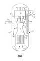
- FIG. 1is a diagram of a natural circulation type boiling water nuclear reactor incorporating a probe system for determining coolant level and flow velocity in the downcomer in accordance with an embodiment of the invention
- FIG. 2is a side view of one possible combination of the probe system that includes a plurality of thermal conductivity (TC) probes at desired locations within the downcomer;
- TCthermal conductivity
- FIG. 3is a side view of another possible combination of the probe system that includes a plurality of thermal conductivity (TC) probes and a plurality of electrical conductive (EC) probes at desired locations within the downcomer;
- TCthermal conductivity
- ECelectrical conductive
- FIG. 4is a side view of another possible combination of the probe system that includes a plurality of electrical conductivity (TC) probes at desired locations within the downcomer, and one or more time-domain reflectometer (TDR) probes; and
- TCelectrical conductivity
- TDRtime-domain reflectometer
- FIG. 5is a side view of yet another possible combination of the probe system that includes a plurality of thermal conductivity (TC) and electrical conductivity (EC) probes at desired locations within the downcomer, and one or more time-domain reflectometer (TDR) probes.
- TCthermal conductivity
- ECelectrical conductivity
- TDRtime-domain reflectometer
- a boiling water reactor 10comprises a reactor pressure vessel 12 having a feedwater inlet 14 for the introduction of recycled steam condensate and/or makeup coolant into the vessel 12 , and a steam outlet 16 for the discharge of produced steam for appropriate work, such as driving electricity-generating turbines.
- a core of heat-producing fissionable fuel 18is located within a lower area of the pressure vessel 12 .
- the fuel core 18is surrounded by a core shroud 20 spaced inward from the wall of the pressure vessel 12 to provide an annular downcomer 22 forming a coolant flow path between the vessel wall and the core shroud 20 .
- the open steam space 26may include a chimney 36 .
- the chimney 36 (if present) and the fuel core shroud 20are spaced radially inward from the wall of the reactor pressure vessel 12 to provide for the annular downcomer 22 , which forms a coolant flow path between the vessel wall and the shroud 20 and the chimney 36 (if present) defining the fuel core 18 and the core outlet plenum 24 , respectively.
- Feedwater coolantenters the pressure vessel 12 through inlet 14 and mixes with cycling liquid water coolant separated from steam by the steam separators 28 .
- the combined coolant waterflows downward in the annular downcomer 22 between the side wall of vessel 12 and the shroud 20 and chimney 36 (if present) to the bottom portion of the vessel 12 .
- the circulating coolant waterthen reverses its direction around the bottom of the core shroud 20 and flows upward through the lower core plenum and into and through the heat-producing core 18 of nuclear fuel, whereupon it emerges as a mixture of steam and liquid water into the core outlet plenum 24 .
- This recycling circuit of coolantis maintained continuously during operation of the reactor to remove heat from the fuel core 18 .
- the circulating coolantcomprising a mixture of steam and water from the fuel core, passes up through the core outlet plenum 24 and into the steam separators 28 , where separated steam phase is directed on upward to the dryers 34 and the liquid water phase is shunted laterally to rejoin the circulating coolant water flowing downward through the annular downcomer 22 to again repeat the cycle.
- One aspect of the inventionis to provide an accurate measurement of the flow velocity or flow rate and the coolant level 38 of the circulating coolant water flowing downward through the annular downcomer 22 , indicated by the arrows in FIG. 1 . This is accomplished by providing a probe system, shown generally at 40 , that is at least partially located within the downcomer 22 of the reactor 10 .
- the probe system 40comprises a combination of a plurality of electrical conductive (EC) probes 42 and/or a plurality of thermal conductivity (TC) probes 44 (also known as heated junction thermocouples (HJT), and one or more time-domain reflectometer (TDR) probes 46 .
- the EC probes 42 with a fixed cell constantare used to measure the electrical conductivity or impedance of the surrounding medium. As the electrical properties of steam and water are dramatically different (steam is less conductive than water), and the location of each EC probe 42 is known, the composition of the coolant flowing downward through the annular downcomer 22 can be determined.
- the coolant level 38 over a larger region of the annular downcomer 22can be determined at discrete points where the EC probes 42 are located.
- the electrical conductivity probes 42provide an indication of the coolant level 38 above and below two adjacent discrete EC probe elevations, except in rare cases in which the coolant level 38 is discernibly located exactly at a probe location.
- An example of an EC probe 42is a type commercially available from Solartron Mobrey Limited, Model No. TB/hyd009.
- the TC (or HJT) probes 44contain a plurality of resistance temperature devices that are employed to measure the thermal conductivity of the surrounding medium. As the thermal properties of steam and water are dramatically different (steam is less conductive than water), and the location of the probe 44 is known, the composition of the coolant flowing downward through the annular downcomer 22 can be inferred. By using a plurality of probes 44 vertically arranged at various known locations within the downcomer 22 , the coolant level 38 over a larger region of the annular downcomer 22 can be determined at discrete points where the TC (or HJT) probes 44 are located.
- the TC probes 44provide an indication of the coolant level 38 above and below two adjacent discrete TC probe elevations, except in rare cases in which the coolant level 38 is discernibly located exactly at a probe location.
- a flowing materialsuch as water or steam, strips more thermal energy from the probe 44 .
- the flow velocity of the coolant water flowing downward through the downcomer 22can be determined.
- An example of a TC probe 44is a type commercially available from Magnetrol International, Inc., Thermatel® Model No. TD1/TD2.
- the TDR probe 46emits one or more electromagnetic pulses down a cable or rod and measures the time delay of the pulse reflection that occurs due to dielectric differences between steam and water. As such, the TDR probe 46 is used to measure the liquid level of the coolant water flowing downward through the downcomer 22 .
- TDR probes 44are types commercially available from Magnetrol International, Inc., Eclipse® Enhanced Model No. 705, and Endress+Hauser, Inc., Model No. Levelflex M FMP41C and FMP45.
- the probe system 40comprises either a combination of EC probes 42 and TDR probes 46 , or a combination of TC probes 44 and TDR probes 46 , or a combination of EC probes 42 , TC probes 44 and TDR probes 46 . That is, the probe system 40 comprises a plurality of conductivity/resistivity probes (EC probes 42 and/or TC (or HJT) probes 44 ) and one or more TDR probes 46 , thereby minimizing the number of penetrations needed in the reactor vessel 12 .
- the EC probes 42 or TC (or HJT) probes 44are placed at desired locations for point water level measurement in conjunction with the TDR probes 46 . Both discontinuous measurements from the conductivity probes 42 , 44 and continuous measurements from the one or more TDR probes 46 are used to calibrate and correct the measurement for the coolant level within the downcomer 22 of the reactor 10 .
- the strengths of each type of probeare combined to provide a synergistic effect that optimizes response time, accuracy, fault determination and operation in a volatile (two phase) environment.
- the EC probes 42can be used in concert with the one or more TDR probes 46 to correct for deviations in water conductivity that may alter the accuracy of the TDR probe 46 .
- the changes in the dielectric constantinfluences the amplitude of the reflected impulse signal from the TDR probe 46 , so the compensation from change in the conductivity change measured by the probes 42 , 44 can be used to adjust the receiver sensitivity (and accuracy) of the TDR probe 46 .
- the combined information of the discrete conductivity probes 42 , 44 and the continuous TDR probes 46can be much more reliable and informative than measurements from conductivity probes and TDR probes alone.
- the TDR probes 46can measure the multiple reflections from the steam/foam interface and the foam/water interface, while the conductivity probes 42 , 44 can confirm the measured information from the TDR probes 46 with different conductivity measurements from the steam layer, the foam layer and the water layer.
- the probe system 40comprises a combination of a plurality of electrical conductive (EC) probes 42 and/or a plurality of thermal conductivity (TC) probes 44 (also known as heated junction thermocouples (HJT), and one or more time-domain reflectometer (TDR) probes 46 .
- ECelectrical conductive
- TCthermal conductivity
- TDRtime-domain reflectometer
- the probe system 40includes a plurality of EC probes 42 placed at desired locations that provide discrete sensing of the coolant level, and a plurality of TC probes 44 at desired locations that provide both discrete sensing of the coolant level and continuous sensing of coolant flow velocity within the downcomer 22 of the reactor 10 .
- the probe system 40includes a plurality of EC probes 42 placed at desired locations that provide discrete sensing of the coolant level, and a TDR probe 46 that extends from substantially the length of the probe system 40 for providing continuous sensing of the coolant level within the downcomer 22 of the reactor 10 .
- the probe system 40includes a plurality of EC probes 42 placed at desired locations that provide discrete sensing of the coolant level, and a plurality of TC probes 44 placed at desired locations that provide both discrete sensing of the coolant level 38 and continuous sensing of coolant flow within the downcomer 22 .
- the probe system 40also includes a TDR probe 46 that extends from substantially the length of the probe system 40 for providing continuous sensing of the coolant level within the downcomer 22 of the reactor 10 .
- the probe system 40determines the coolant level in the downcomer 22 of the reactor 10 . Additionally the TC probes 44 allow the determination of flow velocity. By doing so, the probe system 40 eliminates the need for a differential pressure system that is required in conventional reactor designs, thereby reducing cost and complexity of the reactor design.
- the inventionis not limited by the location of the probe system 40 , and that the invention can be used at other locations to determine the coolant level 38 and flow velocity for a two-phase coolant or a single-phase coolant.
- the probe system 40can be used to measure the water level and flow velocity in a steam generator of a pressurized water reactor (PWR).
- PWRpressurized water reactor
Landscapes
- Physics & Mathematics (AREA)
- Engineering & Computer Science (AREA)
- General Physics & Mathematics (AREA)
- Fluid Mechanics (AREA)
- Thermal Sciences (AREA)
- Plasma & Fusion (AREA)
- General Engineering & Computer Science (AREA)
- High Energy & Nuclear Physics (AREA)
- Electromagnetism (AREA)
- Aviation & Aerospace Engineering (AREA)
- Monitoring And Testing Of Nuclear Reactors (AREA)
Abstract
Description
Claims (8)
Priority Applications (5)
| Application Number | Priority Date | Filing Date | Title |
|---|---|---|---|
| US11/762,986US8532244B2 (en) | 2007-06-14 | 2007-06-14 | System and method for determining coolant level and flow velocity in a nuclear reactor |
| ES08157709TES2399678T3 (en) | 2007-06-14 | 2008-06-06 | System and procedure for determining the level and flow rate of the refrigerant in a nuclear reactor |
| EP08157709AEP2053614B1 (en) | 2007-06-14 | 2008-06-06 | System and method for determining coolant level and flow velocity in a nuclear reactor |
| CN2008100996676ACN101325091B (en) | 2007-06-14 | 2008-06-13 | System and method for determining coolant level and flow velocity in a nuclear reactor |
| JP2008154778AJP5639332B2 (en) | 2007-06-14 | 2008-06-13 | System for determining coolant level and flow velocity in a nuclear reactor |
Applications Claiming Priority (1)
| Application Number | Priority Date | Filing Date | Title |
|---|---|---|---|
| US11/762,986US8532244B2 (en) | 2007-06-14 | 2007-06-14 | System and method for determining coolant level and flow velocity in a nuclear reactor |
Publications (2)
| Publication Number | Publication Date |
|---|---|
| US20080310576A1 US20080310576A1 (en) | 2008-12-18 |
| US8532244B2true US8532244B2 (en) | 2013-09-10 |
Family
ID=39712302
Family Applications (1)
| Application Number | Title | Priority Date | Filing Date |
|---|---|---|---|
| US11/762,986Active - Reinstated2031-04-01US8532244B2 (en) | 2007-06-14 | 2007-06-14 | System and method for determining coolant level and flow velocity in a nuclear reactor |
Country Status (5)
| Country | Link |
|---|---|
| US (1) | US8532244B2 (en) |
| EP (1) | EP2053614B1 (en) |
| JP (1) | JP5639332B2 (en) |
| CN (1) | CN101325091B (en) |
| ES (1) | ES2399678T3 (en) |
Cited By (3)
| Publication number | Priority date | Publication date | Assignee | Title |
|---|---|---|---|---|
| US20100254505A1 (en)* | 2009-04-01 | 2010-10-07 | Ge-Hitachi Nuclear Energy Americas Llc | Methods and apparatuses for operating nuclear reactors and for determining power levels in the nuclear reactors |
| US20180277267A1 (en)* | 2017-03-27 | 2018-09-27 | Ge-Hitachi Nuclear Energy Americas Llc | Acoustic flowmeters and methods of using the same |
| TWI751682B (en)* | 2019-09-05 | 2022-01-01 | 美商西屋電器公司 | Detection apparatus, system, and method for detection of coolant flow rate and temperature in a nuclear environment |
Families Citing this family (15)
| Publication number | Priority date | Publication date | Assignee | Title |
|---|---|---|---|---|
| JP4850537B2 (en)* | 2006-02-27 | 2012-01-11 | 日立Geニュークリア・エナジー株式会社 | Temperature detector for natural circulation boiling water reactor |
| US9803510B2 (en)* | 2011-04-18 | 2017-10-31 | Holtec International | Autonomous self-powered system for removing thermal energy from pools of liquid heated by radioactive materials, and method of the same |
| US11569001B2 (en) | 2008-04-29 | 2023-01-31 | Holtec International | Autonomous self-powered system for removing thermal energy from pools of liquid heated by radioactive materials |
| US9250277B1 (en)* | 2011-03-21 | 2016-02-02 | Northrop Grumman Systems Corporation | Magnetically coupled, high resolution linear position sensor for use in high temperature, high pressure environment |
| WO2012149057A1 (en) | 2011-04-25 | 2012-11-01 | Holtec International, Inc. | Air-cooled heat exchanger and system and method of using the same to remove waste thermal energy from radioactive materials |
| US11504814B2 (en) | 2011-04-25 | 2022-11-22 | Holtec International | Air cooled condenser and related methods |
| JP5677274B2 (en)* | 2011-11-18 | 2015-02-25 | 株式会社東芝 | Reactor water level measurement system |
| JP5740288B2 (en)* | 2011-11-22 | 2015-06-24 | 株式会社東芝 | Reactor water level measurement system |
| FR2992718B1 (en)* | 2012-06-27 | 2014-07-18 | Elta | DEVICE FOR DETECTING THE LEVEL OF A LIQUID CONTAINED IN AN ENCLOSURE |
| US10512990B2 (en) | 2012-12-03 | 2019-12-24 | Holtec International, Inc. | Brazing compositions and uses thereof |
| JP6489904B2 (en)* | 2015-03-31 | 2019-03-27 | 株式会社関電工 | Reactor water level measurement method and apparatus during emergency |
| GB201520374D0 (en)* | 2015-11-19 | 2016-01-06 | Moog Controls Ltd | A method for releasing a fluid from a pressure vessel assembly |
| CN108511094B (en)* | 2017-02-28 | 2024-12-17 | 国核华清(北京)核电技术研发中心有限公司 | Device and method for monitoring reactor core liquid level and cavitation |
| DE102017119502B4 (en)* | 2017-08-25 | 2025-05-22 | Krohne S. A. S. | TDR level measuring device and method for operating a TDR level measuring device |
| KR101969329B1 (en)* | 2018-01-25 | 2019-04-17 | 한국원자력연구원 | Level measuring device |
Citations (26)
| Publication number | Priority date | Publication date | Assignee | Title |
|---|---|---|---|---|
| US3280627A (en) | 1963-05-27 | 1966-10-25 | American Radiator & Standard | Liquid level sensor |
| US4371790A (en) | 1980-09-19 | 1983-02-01 | Rmr Systems, Inc. | Fluid measuring system |
| US4440717A (en) | 1981-09-01 | 1984-04-03 | Combustion Engineering, Inc. | Heated junction thermocouple level measurement apparatus |
| US4592230A (en) | 1983-07-18 | 1986-06-03 | Scandpower, Inc. | Apparatus for and method of determining the liquid coolant level in a nuclear reactor |
| US4786857A (en) | 1986-04-24 | 1988-11-22 | Charles L. Mohr | Methods and apparatus for time domain reflectometry determination of relative proportion, fluid inventory and turbulence |
| US4859076A (en) | 1987-06-05 | 1989-08-22 | Westinghouse Electric Corp. | Differential temperature sensors |
| US4965041A (en) | 1986-10-08 | 1990-10-23 | Kurt Becker | Instrument for monitoring the cooling conditions in a light water reactor |
| US4977385A (en) | 1986-04-23 | 1990-12-11 | Mcqueen Malcolm M | Distributed RTD |
| US5073335A (en)* | 1990-07-10 | 1991-12-17 | General Electric Company | Bwr turbopump recirculation system |
| US5117216A (en) | 1986-04-23 | 1992-05-26 | Fluid Components, Inc. | Distributed RTD |
| US5134772A (en) | 1988-05-02 | 1992-08-04 | Fluid Components, Inc. | Method of making a U-shaped heated extended resistance temperature sensor |
| US5152049A (en) | 1988-05-02 | 1992-10-06 | Fluid Components, Inc. | Method of making a heated extended resistance temperature sensor |
| US5167153A (en) | 1986-04-23 | 1992-12-01 | Fluid Components, Inc. | Method of measuring physical phenomena using a distributed RTD |
| US5201223A (en) | 1988-05-02 | 1993-04-13 | Fluid Components, Inc. | Method of sensing fluid flow and level employing a heated extended resistance temperature sensor |
| US5211904A (en) | 1990-12-10 | 1993-05-18 | General Electric Company | In-vessel water level monitor for boiling water reactors |
| US5220514A (en) | 1990-04-11 | 1993-06-15 | Itt Corporation | Method & apparatus for liquid level conductance probe control unit with increased sensitivity |
| US5221916A (en) | 1988-05-02 | 1993-06-22 | Fluid Components, Inc. | Heated extended resistance temperature sensor |
| US5323430A (en)* | 1991-05-17 | 1994-06-21 | N.V. Tot Keuring Van Elektrotechnische Materialen (Kema) | Method and system for fine control of thermal power of a boiling water reactor with natural circulation |
| EP0618428A2 (en) | 1993-03-27 | 1994-10-05 | Solartron Group Limited | Fluid level sensing systems |
| EP0627615A1 (en) | 1993-05-29 | 1994-12-07 | Solartron Group Limited | Fluid level sensing systems |
| US5615573A (en) | 1994-07-08 | 1997-04-01 | The Boc Group, Inc. | Level detector |
| US5798698A (en) | 1995-03-07 | 1998-08-25 | Gestra Gmbh | Method of monitoring the level of a liquid in a container |
| US5913250A (en) | 1997-10-29 | 1999-06-15 | Fluid Components Intl | Pressure compensated thermal flow meter |
| US6208254B1 (en) | 1999-09-15 | 2001-03-27 | Fluid Components Intl | Thermal dispersion mass flow rate and liquid level switch/transmitter |
| US6219398B1 (en) | 1998-07-28 | 2001-04-17 | Ce Nuclear Power Llc | Heated junction thermocouple cable arrangement |
| WO2003095954A1 (en) | 2002-05-07 | 2003-11-20 | Framatome Anp Gmbh | Method for determining a position parameter for a boundary layer of a medium contained in a container |
Family Cites Families (6)
| Publication number | Priority date | Publication date | Assignee | Title |
|---|---|---|---|---|
| US4350968A (en)* | 1981-01-29 | 1982-09-21 | The United States Of America As Represented By The United States Department Of Energy | Liquid level detector |
| US4617168A (en)* | 1984-04-18 | 1986-10-14 | General Electric Company | Apparatus and method for reactor monitoring |
| JPS63223591A (en)* | 1987-03-13 | 1988-09-19 | 株式会社日立製作所 | natural circulation reactor |
| JP2001042080A (en)* | 1999-07-29 | 2001-02-16 | Toshiba Corp | Reactor process volume measurement device |
| JP4533670B2 (en)* | 2004-05-31 | 2010-09-01 | 株式会社東芝 | Boiling water reactor facilities |
| JP4656889B2 (en) | 2004-08-13 | 2011-03-23 | 日立Geニュークリア・エナジー株式会社 | Core flow measurement device |
- 2007
- 2007-06-14USUS11/762,986patent/US8532244B2/enactiveActive - Reinstated
- 2008
- 2008-06-06EPEP08157709Apatent/EP2053614B1/enactiveActive
- 2008-06-06ESES08157709Tpatent/ES2399678T3/enactiveActive
- 2008-06-13JPJP2008154778Apatent/JP5639332B2/enactiveActive
- 2008-06-13CNCN2008100996676Apatent/CN101325091B/enactiveActive
Patent Citations (31)
| Publication number | Priority date | Publication date | Assignee | Title |
|---|---|---|---|---|
| US3280627A (en) | 1963-05-27 | 1966-10-25 | American Radiator & Standard | Liquid level sensor |
| US4371790A (en) | 1980-09-19 | 1983-02-01 | Rmr Systems, Inc. | Fluid measuring system |
| US4440717A (en) | 1981-09-01 | 1984-04-03 | Combustion Engineering, Inc. | Heated junction thermocouple level measurement apparatus |
| US4592230A (en) | 1983-07-18 | 1986-06-03 | Scandpower, Inc. | Apparatus for and method of determining the liquid coolant level in a nuclear reactor |
| US4592230B1 (en) | 1983-07-18 | 1990-10-16 | Scandpower Inc | |
| US5167153A (en) | 1986-04-23 | 1992-12-01 | Fluid Components, Inc. | Method of measuring physical phenomena using a distributed RTD |
| US4977385A (en) | 1986-04-23 | 1990-12-11 | Mcqueen Malcolm M | Distributed RTD |
| US5355727A (en) | 1986-04-23 | 1994-10-18 | Fluid Components, Inc. | Method of making average mass flow velocity measurements |
| US5117216A (en) | 1986-04-23 | 1992-05-26 | Fluid Components, Inc. | Distributed RTD |
| US4786857A (en) | 1986-04-24 | 1988-11-22 | Charles L. Mohr | Methods and apparatus for time domain reflectometry determination of relative proportion, fluid inventory and turbulence |
| US4965041A (en) | 1986-10-08 | 1990-10-23 | Kurt Becker | Instrument for monitoring the cooling conditions in a light water reactor |
| US4859076A (en) | 1987-06-05 | 1989-08-22 | Westinghouse Electric Corp. | Differential temperature sensors |
| US5201223A (en) | 1988-05-02 | 1993-04-13 | Fluid Components, Inc. | Method of sensing fluid flow and level employing a heated extended resistance temperature sensor |
| US5134772A (en) | 1988-05-02 | 1992-08-04 | Fluid Components, Inc. | Method of making a U-shaped heated extended resistance temperature sensor |
| US5221916A (en) | 1988-05-02 | 1993-06-22 | Fluid Components, Inc. | Heated extended resistance temperature sensor |
| US5152049A (en) | 1988-05-02 | 1992-10-06 | Fluid Components, Inc. | Method of making a heated extended resistance temperature sensor |
| US5220514A (en) | 1990-04-11 | 1993-06-15 | Itt Corporation | Method & apparatus for liquid level conductance probe control unit with increased sensitivity |
| US5073335A (en)* | 1990-07-10 | 1991-12-17 | General Electric Company | Bwr turbopump recirculation system |
| US5211904A (en) | 1990-12-10 | 1993-05-18 | General Electric Company | In-vessel water level monitor for boiling water reactors |
| US5323430A (en)* | 1991-05-17 | 1994-06-21 | N.V. Tot Keuring Van Elektrotechnische Materialen (Kema) | Method and system for fine control of thermal power of a boiling water reactor with natural circulation |
| US5565851A (en) | 1993-03-27 | 1996-10-15 | Solartron Group Limited | Fluid level sensing systems |
| EP0618428A2 (en) | 1993-03-27 | 1994-10-05 | Solartron Group Limited | Fluid level sensing systems |
| EP0627615A1 (en) | 1993-05-29 | 1994-12-07 | Solartron Group Limited | Fluid level sensing systems |
| US5553494A (en) | 1993-05-29 | 1996-09-10 | Solartron Group Limited | Fluid level sensing systems |
| US5615573A (en) | 1994-07-08 | 1997-04-01 | The Boc Group, Inc. | Level detector |
| US5798698A (en) | 1995-03-07 | 1998-08-25 | Gestra Gmbh | Method of monitoring the level of a liquid in a container |
| US5913250A (en) | 1997-10-29 | 1999-06-15 | Fluid Components Intl | Pressure compensated thermal flow meter |
| US6219398B1 (en) | 1998-07-28 | 2001-04-17 | Ce Nuclear Power Llc | Heated junction thermocouple cable arrangement |
| US6208254B1 (en) | 1999-09-15 | 2001-03-27 | Fluid Components Intl | Thermal dispersion mass flow rate and liquid level switch/transmitter |
| US6628202B2 (en) | 1999-09-15 | 2003-09-30 | Fluid Components Intl | Thermal dispersion mass flow rate and liquid level switch/transmitter |
| WO2003095954A1 (en) | 2002-05-07 | 2003-11-20 | Framatome Anp Gmbh | Method for determining a position parameter for a boundary layer of a medium contained in a container |
Non-Patent Citations (1)
| Title |
|---|
| Persson, Magnus and Wraith, Jon M., Shaft-Mounted Time Domain Reflectometry Probe for Water Content and Electrical Conductivity Measurements, Vadose Zone Journal, p. 316-319, 2002, Soil Science Society of America.* |
Cited By (5)
| Publication number | Priority date | Publication date | Assignee | Title |
|---|---|---|---|---|
| US20100254505A1 (en)* | 2009-04-01 | 2010-10-07 | Ge-Hitachi Nuclear Energy Americas Llc | Methods and apparatuses for operating nuclear reactors and for determining power levels in the nuclear reactors |
| US9324465B2 (en) | 2009-04-01 | 2016-04-26 | Ge-Hitachi Nuclear Energy Americas Llc | Methods and apparatuses for operating nuclear reactors and for determining power levels in the nuclear reactors |
| US20180277267A1 (en)* | 2017-03-27 | 2018-09-27 | Ge-Hitachi Nuclear Energy Americas Llc | Acoustic flowmeters and methods of using the same |
| US10650931B2 (en)* | 2017-03-27 | 2020-05-12 | Ge-Hitachi Nuclear Energy Americas Llc | Acoustic flowmeters and methods of using the same |
| TWI751682B (en)* | 2019-09-05 | 2022-01-01 | 美商西屋電器公司 | Detection apparatus, system, and method for detection of coolant flow rate and temperature in a nuclear environment |
Also Published As
| Publication number | Publication date |
|---|---|
| CN101325091A (en) | 2008-12-17 |
| US20080310576A1 (en) | 2008-12-18 |
| EP2053614A3 (en) | 2011-01-05 |
| EP2053614B1 (en) | 2013-01-02 |
| CN101325091B (en) | 2013-08-28 |
| ES2399678T3 (en) | 2013-04-02 |
| JP5639332B2 (en) | 2014-12-10 |
| JP2008309792A (en) | 2008-12-25 |
| EP2053614A2 (en) | 2009-04-29 |
Similar Documents
| Publication | Publication Date | Title |
|---|---|---|
| US8532244B2 (en) | System and method for determining coolant level and flow velocity in a nuclear reactor | |
| US20130177122A1 (en) | Reactor Water-Level/Temperature Measurement Apparatus | |
| JP2007316059A (en) | Thermal fluid phenomenon simulation method and simulation test apparatus | |
| Pacio et al. | Advanced Thermal-Hydraulic experiments and instrumentation for heavy liquid metal reactors | |
| Xu et al. | CFD modeling development for DNB prediction of rod bundle with mixing vanes under PWR conditions | |
| Gui et al. | Experimental investigation on quenching behavior during reflooding in a 3× 3 dual-cooled annular rod bundle | |
| Eibeck | An experimental investigation of the heat transfer effects of a longitudinal vortex embedded in a turbulent boundary layer | |
| Dedov et al. | Hydrodynamics and heat transfer in swirl flow under conditions of one-side heating. Part 1: Pressure drop and single-phase heat transfer | |
| Kamide et al. | Sodium experiments of buoyancy-driven penetration flow into low-power subassemblies in a sodium-cooled fast reactor during natural circulation decay heat removal | |
| JP2001272494A (en) | A method for instantaneously measuring the void fraction in a flow path composed of two phases of gas and liquid. | |
| Del Moro et al. | ATHENA main heat exchanger conceptual design and thermal-hydraulic assessment with RELAP5 code | |
| Wantland et al. | Dynamic boiling tests in a 19-pin simulated LMFBR fuel assembly | |
| US11289221B2 (en) | Detection apparatus, system, and method for detection of coolant flow rate and temperature in a nuclear environment | |
| CN220794635U (en) | Electromagnetic boiler heat exchange efficiency testing device | |
| JPS58172540A (en) | void meter | |
| Liu et al. | Critical power characteristics in 37-rod tight lattice bundles under transient conditions | |
| Akiyama et al. | Study on post-BT heat transfer in a full scale bwr (8× 8) rod bundle | |
| Griffith et al. | Dryout front modeling for rod bundles | |
| Kawaji | Transient non-equilibrium two-phase flow: reflooding of a vertical flow channel | |
| Turnage | Progress Report for January-March 1980, NUREG/CR-1647 (ORNL/NUREG/TM-403),(September 1980). | |
| Carver et al. | INSTABILITIES IN FLOW THROUGH MULTIROD BUNDLES AND THEIR EFFECT ON DRYOUT. | |
| Cubizolles et al. | PWR bundle heat transfer tests in the OMEGA-2 test facility | |
| KR20250051433A (en) | Water level measuring apparatus for pressure tank and method thereof | |
| Paruya et al. | Simulation of oscillations in boiling flow in a natural circulation evaporator | |
| Hassan | Interpretation of conductivity-sensitive liquid-level transducer signals in a small break loss-of-coolant accident test facility |
Legal Events
| Date | Code | Title | Description |
|---|---|---|---|
| AS | Assignment | Owner name:GENERAL ELECTRIC COMPANY, NEW YORK Free format text:ASSIGNMENT OF ASSIGNORS INTEREST;ASSIGNORS:BRISSON, BRUCE WILLIAM;MORRIS, WILLIAM GUY;ZHENG, DANIAN;AND OTHERS;REEL/FRAME:019429/0769;SIGNING DATES FROM 20070604 TO 20070612 Owner name:GENERAL ELECTRIC COMPANY, NEW YORK Free format text:ASSIGNMENT OF ASSIGNORS INTEREST;ASSIGNORS:BRISSON, BRUCE WILLIAM;MORRIS, WILLIAM GUY;ZHENG, DANIAN;AND OTHERS;SIGNING DATES FROM 20070604 TO 20070612;REEL/FRAME:019429/0769 | |
| AS | Assignment | Owner name:GE-HITACHI NUCLEAR ENERGY AMERICAS LLC, NORTH CARO Free format text:ASSIGNMENT OF ASSIGNORS INTEREST;ASSIGNOR:GENERAL ELECTRIC COMPANY;REEL/FRAME:022083/0701 Effective date:20081009 | |
| FEPP | Fee payment procedure | Free format text:PAYOR NUMBER ASSIGNED (ORIGINAL EVENT CODE: ASPN); ENTITY STATUS OF PATENT OWNER: LARGE ENTITY | |
| STCF | Information on status: patent grant | Free format text:PATENTED CASE | |
| CC | Certificate of correction | ||
| REMI | Maintenance fee reminder mailed | ||
| FPAY | Fee payment | Year of fee payment:4 | |
| SULP | Surcharge for late payment | ||
| FEPP | Fee payment procedure | Free format text:MAINTENANCE FEE REMINDER MAILED (ORIGINAL EVENT CODE: REM.); ENTITY STATUS OF PATENT OWNER: LARGE ENTITY | |
| LAPS | Lapse for failure to pay maintenance fees | Free format text:PATENT EXPIRED FOR FAILURE TO PAY MAINTENANCE FEES (ORIGINAL EVENT CODE: EXP.); ENTITY STATUS OF PATENT OWNER: LARGE ENTITY | |
| STCH | Information on status: patent discontinuation | Free format text:PATENT EXPIRED DUE TO NONPAYMENT OF MAINTENANCE FEES UNDER 37 CFR 1.362 | |
| FP | Lapsed due to failure to pay maintenance fee | Effective date:20210910 | |
| PRDP | Patent reinstated due to the acceptance of a late maintenance fee | Effective date:20220101 | |
| FEPP | Fee payment procedure | Free format text:PETITION RELATED TO MAINTENANCE FEES FILED (ORIGINAL EVENT CODE: PMFP); ENTITY STATUS OF PATENT OWNER: LARGE ENTITY Free format text:PETITION RELATED TO MAINTENANCE FEES GRANTED (ORIGINAL EVENT CODE: PMFG); ENTITY STATUS OF PATENT OWNER: LARGE ENTITY Free format text:SURCHARGE, PETITION TO ACCEPT PYMT AFTER EXP, UNINTENTIONAL (ORIGINAL EVENT CODE: M1558); ENTITY STATUS OF PATENT OWNER: LARGE ENTITY | |
| MAFP | Maintenance fee payment | Free format text:PAYMENT OF MAINTENANCE FEE, 8TH YEAR, LARGE ENTITY (ORIGINAL EVENT CODE: M1552); ENTITY STATUS OF PATENT OWNER: LARGE ENTITY Year of fee payment:8 | |
| STCF | Information on status: patent grant | Free format text:PATENTED CASE | |
| FEPP | Fee payment procedure | Free format text:11.5 YR SURCHARGE- LATE PMT W/IN 6 MO, LARGE ENTITY (ORIGINAL EVENT CODE: M1556); ENTITY STATUS OF PATENT OWNER: LARGE ENTITY | |
| MAFP | Maintenance fee payment | Free format text:PAYMENT OF MAINTENANCE FEE, 12TH YEAR, LARGE ENTITY (ORIGINAL EVENT CODE: M1553); ENTITY STATUS OF PATENT OWNER: LARGE ENTITY Year of fee payment:12 |