US8532242B2 - Distributed antenna system with combination of both all digital transport and hybrid digital/analog transport - Google Patents
Distributed antenna system with combination of both all digital transport and hybrid digital/analog transportDownload PDFInfo
- Publication number
- US8532242B2 US8532242B2US12/913,179US91317910AUS8532242B2US 8532242 B2US8532242 B2US 8532242B2US 91317910 AUS91317910 AUS 91317910AUS 8532242 B2US8532242 B2US 8532242B2
- Authority
- US
- United States
- Prior art keywords
- analog
- spectrum
- digital
- unit
- bands
- Prior art date
- Legal status (The legal status is an assumption and is not a legal conclusion. Google has not performed a legal analysis and makes no representation as to the accuracy of the status listed.)
- Ceased, expires
Links
Images


Classifications
- H—ELECTRICITY
- H04—ELECTRIC COMMUNICATION TECHNIQUE
- H04B—TRANSMISSION
- H04B7/00—Radio transmission systems, i.e. using radiation field
- H04B7/24—Radio transmission systems, i.e. using radiation field for communication between two or more posts
- H04B7/26—Radio transmission systems, i.e. using radiation field for communication between two or more posts at least one of which is mobile
- H04B7/2603—Arrangements for wireless physical layer control
- H04B7/2606—Arrangements for base station coverage control, e.g. by using relays in tunnels
- H—ELECTRICITY
- H04—ELECTRIC COMMUNICATION TECHNIQUE
- H04B—TRANSMISSION
- H04B7/00—Radio transmission systems, i.e. using radiation field
- H04B7/14—Relay systems
- H04B7/15—Active relay systems
- H04B7/155—Ground-based stations
- H04B7/15507—Relay station based processing for cell extension or control of coverage area
- H—ELECTRICITY
- H04—ELECTRIC COMMUNICATION TECHNIQUE
- H04B—TRANSMISSION
- H04B1/00—Details of transmission systems, not covered by a single one of groups H04B3/00 - H04B13/00; Details of transmission systems not characterised by the medium used for transmission
- H04B1/38—Transceivers, i.e. devices in which transmitter and receiver form a structural unit and in which at least one part is used for functions of transmitting and receiving
- H04B1/40—Circuits
- H—ELECTRICITY
- H04—ELECTRIC COMMUNICATION TECHNIQUE
- H04B—TRANSMISSION
- H04B7/00—Radio transmission systems, i.e. using radiation field
- H04B7/02—Diversity systems; Multi-antenna system, i.e. transmission or reception using multiple antennas
- H04B7/022—Site diversity; Macro-diversity
Definitions
- the present applicationis related to commonly assigned and co-pending U.S. patent application Ser. No. 11/150,820 (hereafter “the '820 application”) entitled “PROVIDING WIRELESS COVERAGE INTO SUBSTANTIALLY CLOSED ENVIRONMENTS”, filed on Jun. 10, 2005 (currently pending).
- the present applicationis also related to commonly assigned and co-pending U.S. patent application Ser. No. 12/775,897 (hereafter “the '897 application”) entitled “PROVIDING WIRELESS COVERAGE INTO SUBSTANTIALLY CLOSED ENVIRONMENTS”, filed on May 7, 2010 (currently pending).
- the present applicationis also related to commonly assigned and co-pending U.S. patent application Ser. No.
- DASDistributed Antenna Systems
- a DASmay distribute antennas within a building.
- the antennasare typically connected to a radio frequency (RF) signal source, such as a service provider.
- RFradio frequency
- Various methods of transporting the RF signal from the RF signal source to the antennashave been implemented in the art.
- a communication systemincludes a master host unit, a first hybrid expansion unit coupled to the master host unit by a first digital communication link, a first analog remote antenna unit coupled to the first hybrid expansion unit by a first analog communication link, and a first digital remote antenna unit coupled to the master host unit by a second digital communication link.
- the master host unitis adapted to communicate analog signals with at least a first service provider interface using a first set of bands of analog spectrum.
- the master host unit and the first hybrid expansion unitare adapted to communicate first N-bit words of digitized spectrum over the first digital communication link.
- the first hybrid expansion unitis further adapted to convert between the first N-bit words of digitized spectrum and a second set of bands of analog spectrum.
- the first hybrid expansion unit and the first analog remote antenna unitare adapted to communicate the second set of bands of analog spectrum over the analog communication medium.
- the first analog remote antenna unitis further adapted to transmit and receive a first plurality of wireless signals over a first plurality of air interfaces.
- the master host unit and the first digital remote antenna unitare adapted to communicate second N-bit words of digitized spectrum over the second digital communication link.
- the first digital remote antenna unitis further adapted to convert between the second N-bit words of digitized spectrum and a third set of bands of analog spectrum.
- the first digital remote antenna unitif further adapted to transmit and receive second wireless signals over a second plurality of air interfaces.
- FIG. 1is a block diagram of one embodiment of a system for providing wireless coverage into a substantially enclosed environment.
- FIG. 2is a block diagram of one embodiment of a master host unit for the system of FIG. 1 .
- FIG. 3is a block diagram of one embodiment of a hybrid expansion unit for the system of FIG. 1 .
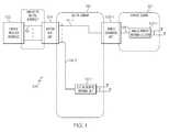
- FIG. 4is a block diagram of one embodiment of an analog remote antenna cluster for the system of FIG. 1 .
- FIG. 5is a block diagram of one embodiment of a master analog remote antenna unit for the analog remote antenna unit cluster of FIG. 4 .
- FIG. 6is a block diagram of one embodiment of a slave analog remote antenna unit for the analog remote antenna unit cluster of FIG. 4 .
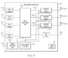
- FIG. 7is a block diagram of one embodiment of a digital remote antenna unit for the system of FIG. 1 .
- FIG. 8is a block diagram of one embodiment of a RF module for the digital remote antenna unit of FIG. 7 .
- FIG. 9is a block diagram of another embodiment of a system for providing wireless coverage into a substantially enclosed environment.
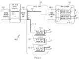
- FIG. 10is a block diagram of another embodiment of a system for providing wireless coverage into a substantially enclosed environment.
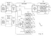
- FIG. 11is a block diagram of another embodiment of a system for providing wireless coverage into a substantially enclosed environment.
- FIG. 12is a block diagram of one embodiment of a digital expansion unit for the system of FIG. 8 .
- FIG. 13is a block diagram of another embodiment of a system for providing wireless coverage into a substantially enclosed environment.
- FIG. 14is a block diagram of another embodiment of a system for providing wireless coverage into a substantially enclosed environment.
- FIG. 1is a block diagram of one embodiment of a system 100 for providing wireless coverage into a substantially enclosed environment.
- the system 100includes at least one service provider interface 102 , at least one master host unit (MHU) 104 , at least one hybrid expansion unit (HEU) 106 , at least one analog remote antenna cluster (ARAC) 108 , and at least one digital remote antenna unit 110 .
- example system 100includes hybrid expansion unit 106 - 1 , analog remote antenna cluster 108 - 1 , and digital remote antenna unit 110 - 1 .
- Other example systemsinclude greater or fewer service provider interfaces 102 , master host units 104 , hybrid expansion units 106 , analog remote antenna clusters 108 , and digital remote antenna units 110 .
- Service provider interface 102may include an interface to one or more of a base transceiver station (BTS), a repeater, a bi-directional amplifier, a base station hotel or other appropriate interface for one or more service provider networks.
- BTSbase transceiver station
- service provider interface 102provides an interface to a plurality of services from one or more service providers. The services may operate using various wireless protocols and in various bands of frequency spectrum.
- the servicesmay include, but are not limited to, 800 MHz cellular service, 1.9 GHz Personal Communication Services (PCS), Specialized Mobile Radio (SMR) services, Enhanced Special Mobile Radio (ESMR) services at both 800 MHz and 900 MHz, 1800 MHz and 2100 MHz Advanced Wireless Services (AWS), 700 MHz uC/ABC Single Input Single Output (SISO) and Multiple Input Multiple Output (MIMO) services, two way paging services, video services, Public Safety (PS) services at 450 MHz, 900 MHz and 1800 MHz Global System for Mobile Communications (GSM), 2100 MHz Universal Mobile Telecommunications System (UMTS), Worldwide Interoperability for Microwave Access (WiMAX), 3rd Generation Partnership Projects (3GPP) Long Term Evolution (LTE), or other appropriate communication services.
- GSMGlobal System for Mobile Communications
- UMTSUniversal Mobile Telecommunications System
- WiMAXWorldwide Interoperability for Microwave Access
- 3GPP3rd Generation Partnership Projects Long Term Evolution
- service provider interface 102is connected to master host unit 104 over at least one analog communication link 112 .
- Each analog communication link 112includes two analog communication media, such as coaxial cables or fiber optic cables. One analog communication media is for downstream communication and the other is for upstream communication. The downstream and upstream analog communication media have been shown as a single analog communication link 112 for simplicity. In other embodiments, each analog communication link 112 only includes a single physical media, which is used to carry both the downlink and uplink streams between the service provider interface 102 and the master host unit 104 .
- the master host unit 104receives downstream bands of radio frequency (RF) spectrum from the at least one service provider interface 102 over the at least one analog communication link 112 .
- the master host unit 104sends upstream bands of radio frequency (RF) spectrum to the at least one service provider interface 102 over the at least one analog communication link 112 .
- the service provider interface 102 and the master host unit 104are connected over at least one digital communication link using at least one digital communication media.
- separate analog communications links 112are used for each service provider interface 102 .
- this disclosuredescribes at least one analog communication link 112 , the format of this interface is not essential to operation of system 100 .
- the master host unit 104converts the analog signal to a digital format as described below. If a digital interface is used, the master host unit 104 will either communicate the digital data as is or reformat the data into a representation that can be used for transport within the digital domain 116 described below.
- frequency division multiplexingFDM
- TDMtime division multiplexing
- WDMoptical wavelength division multiplexing
- System 100uses both digital and analog transport to extend the coverage of the wireless services into the substantially enclosed environment.
- system 100uses digital transport over at least one digital communication link 114 to transport digitized RF spectrum between the master host unit 104 and the at least one hybrid expansion unit 106 and between the master host unit 104 and the at least one digital expansion unit 124 .
- Each digital communication link 114includes two digital communication media, such as fiber optic cables.
- One digital communication mediumis for downstream communication and the other is for upstream communication.
- the downstream and upstream digital communication mediahave been shown as a single digital communication link 114 for simplicity.
- the areas of digital transportare called the digital domain 116 .
- digital transportcan be used to transport between other components as well and the digital domain 116 is more expansive.
- each digital communication link 114only includes a single physical media, which is used to carry both the downlink and uplink streams between the master host unit 104 and the at least one digital expansion unit 124 .
- optical multiplexing techniquesi.e., wavelength division multiplexing (WDM), coarse wavelength division multiplexing (CWDM), or dense wavelength division multiplexing (DWDM) are used to achieve a duplex connection over the single medium.
- While an optical fiberis used in the example system 100 , other appropriate communication media can also be used for the digital transport.
- other embodimentsuse free space optics, high speed copper or other wired, wireless, or optical communication media for digital transport instead of the optical fibers used in each of the at least one digital communication link 114 .
- the bands of RF spectrum provided by the service provider interface 102can be transported over long distances with minimal errors and more resiliency and robustness to signal loss and distortion of the physical medium.
- system 100may extend coverage for wireless services to buildings located significant distances from the service provider interface 102 .
- system 100uses analog transport over at least one analog communication link 118 between the at least one hybrid expansion unit 106 and the at least one analog remote antenna cluster 108 to extend the reach of the digital transport into the substantially enclosed environment.
- Each analog communication link 118includes two analog communication media, such as coaxial cable.
- One analog communication mediais for downstream communication and the other is for upstream communication.
- the downstream and upstream analog communication mediahave been shown as a single analog communication link 118 for simplicity.
- coaxial cableis used in the example system 100
- other appropriate communication mediacan also be used for the analog transport.
- the areas of analog transportare called the analog domain 120 .
- analog transportcan be used to transport between other components as well and the analog domain 120 is more expansive.
- each analog communication link 118only includes a single physical medium, which is used to carry both the downlink and uplink streams between each hybrid expansion unit 106 and each analog remote antenna cluster 108 .
- frequency division multiplexingFDM
- TDMtime division multiplexing
- WDMoptical wavelength division multiplexing
- the various components of system 100convert the various bands of RF spectrum between radio frequencies (RF), various intermediate frequencies (IF), digitized bands of RF spectrum, and digitized IF.
- RFradio frequencies
- IFintermediate frequencies
- the inventioncan be generalized to convert between analog and digital signals. These various conversions require that the digital domain 116 and the analog domain 120 be synchronized in time and frequency. Time synchronization is important to the sampling and reconstruction of the signals. Time synchronization is also important when time alignment of signals in the various parallel branches of the system is necessary. Frequency synchronization is important to maintaining the absolute frequency of the signals at the external interfaces of the system.
- a common reference clockis distributed throughout both the digital domain 116 and the analog domain 120 as described in detail below. This common clock allows for accurate conversion and recovery between RF, IF, digitized bands of RF spectrum, and digitized IF, or more broadly between analog spectrum and digital spectrum.
- FIG. 2is a block diagram of one embodiment of the Master host unit 104 of system 100 .
- Master host unit 104includes at least one digital-analog conversion unit (DACU) 202 , at least one digital multiplexing unit (DMU) 204 , at least one digital input-output unit (DIOU) 206 , at least one central processing unit (CPU) 208 , at least one master clock distribution unit (MCDU) 210 , and at least one power supply 212 .
- DACUdigital-analog conversion unit
- DMUdigital multiplexing unit
- DIOUdigital input-output unit
- CPUcentral processing unit
- MCDUmaster clock distribution unit
- power supply 212at least one power supply 212 .
- the example master host unit 104also includes at least one splitter/combiner 214 .
- the master host unit 104communicates at least one band of analog spectrum with the at least one service provider interface 102 .
- Each DACU 202is coupled with at least one service provider interface 102 .
- These couplingsmay be accomplished in various ways.
- service provider interface 102 - 1is directly coupled to DACU 202 - 1 through analog communication link 112 - 1 .
- service provider interface 102 - 2is coupled to a first side of splitter/combiner 214 - 1 through analog communication link 112 - 2
- DACU 202 - 2is coupled to a second side of splitter/combiner 214 - 1 through analog communication link 112 - 3
- DACU 202 - 3is coupled to the second side of splitter/combiner 214 - 1 through analog communication link 112 - 4 .
- service provider interface 102 - 3is coupled to a first side of splitter/combiner 214 - 2 through analog communication link 112 - 5
- service provider interface 102 -Nis coupled to the first side of splitter/combiner 214 - 2 through analog communication link 112 - 6
- DACU 202 -Nis coupled to a second side of splitter/combiner 214 - 2 through analog communication link 112 - 7 .
- each analog communication link 112 of system 100represents two analog media, one for downstream communication and one for upstream communication. In other embodiments, each link includes greater or fewer analog medium.
- the master host unitcommunicates at least one band of digital spectrum with at least one service provider interface across at least one digital communication link using digital data or digitized spectrum.
- the signals from the service provider interfaces 102 - 1 , 102 - 2 , 102 - 3 , through 102 -Nare first converted from analog to digital before being transmitted across the at least one digital communication link to the master host unit 104 .
- Each DACU 202operates to convert between at least one band of analog spectrum and N-bit words of digitized spectrum.
- each DACU 202is implemented with a Digital/Analog Radio Transceiver (DART board) commercially available from ADC Telecommunications, Inc. of Eden Prairie, Minn. as part of the FlexWaveTM Prism line of products.
- DART boardDigital/Analog Radio Transceiver
- the DART boardis also described in U.S. patent application Ser. No. 11/627,251, assigned to ADC Telecommunications, Inc., published in U.S. Patent Application Publication No. 2008/0181482, and incorporated herein by reference.
- the bands of analog spectruminclude signals in the frequency spectrum used to transport a wireless service, such as any of the wireless services described above.
- master host unit 104enables the aggregation and transmission of a plurality of services to a plurality of buildings or other structures so as to extend the wireless coverage of multiple services into the structures with a single platform.
- the DMU 204multiplexes N-bit words of digitized spectrum received from a plurality of DACU 202 (DACU 202 - 1 through DACU 202 -N) and outputs at least one multiplexed signal to at least one DIOU 206 (DIOU 206 - 1 through DIOU 206 -N).
- the DMU 204also demultiplexes at least one multiplexed signal received from at least one DIOU 206 and outputs demultiplexed N-bit words of digitized spectrum to a plurality of DACU 202 .
- each DMU 204is implemented with a Serialized RF (SeRF board) commercially available from ADC Telecommunications, Inc. of Eden Prairie, Minn.
- SeRF boardis also described in U.S. patent application Ser. No. 11/627,251, assigned to ADC Telecommunications, Inc., published in U.S. Patent Application Publication No. 2008/0181482, and incorporated herein by reference.
- Each DIOU 206communicates at least one digitized multiplexed signal across at least one digital communication link 114 (digital communication link 114 - 1 through digital communication link 114 -N) using digital transport.
- the digitized multiplexed signal communicated across the digital communication link 114includes N-bit words of digitized spectrum.
- Each DIOU 206also receives at least one digitized multiplexed signal from the at least one digital communication link 114 using digital transport and sends the at least one digitized multiplexed signal to the DMU 204 .
- the digital communication link 114 - 1is connected to hybrid expansion unit 106 - 1 and digital communication link 114 - 2 is connected to digital remote antenna unit 110 - 1 .
- DIOU 206 - 1communicates using digital transport with hybrid expansion unit 106 - 1 and DIOU 206 - 2 communicates using digital transport with digital remote antenna unit 110 - 1 .
- each digital communication link 114represents two digital media, one for downstream communication and one for upstream communication. In addition to carrying the digitized multiplexed signals, each digital communication link 114 may also used to communicate other types of information such as system management information, control information, configuration information and telemetry information.
- the hybrid expansion unit 106 and digital remote antenna unit 110are described in detail below.
- Master clock distribution unit 210generates a digital master reference clock signal. This signal is generated using any stable oscillator, such as a temperature compensated crystal oscillator (TCXO), an oven controlled crystal oscillator (OCXO), or a voltage controlled crystal oscillator (VCXO). In the embodiment shown in FIG. 2 , the stable oscillator is included in the master clock distribution unit 210 . In other embodiments, a reference clock external to the master host unit is used, such as a clock from a base station, a GPS unit, or a cesium atomic clock. In embodiments where digital data is communicated between service provider interface 102 and master host unit 104 , the master clock distribution unit 210 may derive the reference clock signal from the digital data stream itself or an external clock signal may be used.
- TCXOtemperature compensated crystal oscillator
- OXOoven controlled crystal oscillator
- VXOvoltage controlled crystal oscillator
- a reference clock external to the master host unitis used, such as a clock from a base station, a
- the digital master reference clock signalis supplied to each DACU 202 and each DMU 204 in the master host unit 104 .
- Each DACU 202uses the clock to convert between at least one band of analog spectrum and N-bit words of digitized spectrum.
- the DMU 204uses the clock to multiplex the various streams of N-bit words of digitized spectrum together and outputs the multiplexed signal to each DIOU 206 .
- the downstream digital data streams output by each DIOU 206are synchronized to the digital master reference clock signal.
- the digital master reference clock signalis distributed to each hybrid expansion unit 106 and each digital expansion unit 124 through each corresponding digital communication link 114 .
- CPU 208is used to control each DACU 202 and each DMU 204 .
- An input/output (I/O) line 216 coupled to CPU 208is used for network monitoring and maintenance.
- I/O line 216is an Ethernet port used for external communication with the system.
- Other communication protocolssuch as Universal Serial Bus (USB), IEEE 1394 (FireWire), and serial may also be used.
- Power supply 212is used to power various components within master host unit 104 .
- FIG. 3is a block diagram of one embodiment of a hybrid expansion unit 106 of system 100 .
- Hybrid expansion unit 106 of system 100includes at least one digital input-output unit (DIOU) 302 , at least one digital multiplexing unit (DMU) 304 , at least one digital-analog conversion unit (DACU) 306 , at least one analog multiplexing unit (AMU) 308 , at least one central processing unit (CPU) 310 , at least one digital expansion clock unit (DECU) 312 , at least one analog domain reference clock unit (ADRCU) 314 , and at least one power supply 316 .
- DIOUdigital input-output unit
- DMUdigital multiplexing unit
- DACUdigital-analog conversion unit
- AMUanalog multiplexing unit
- CPUcentral processing unit
- DECUdigital expansion clock unit
- ADRCUanalog domain reference clock unit
- Each hybrid expansion unit 106communicates at least one band of digitized spectrum with the master host unit 104 in the form of a multiplexed digitized signal containing N-bit words of digitized spectrum.
- the multiplexed digitized signalis received at the at least one DIOU 302 through at least one digital communication link 114 .
- only one DIOU 302 - 1is necessary if the hybrid expansion unit 106 is only coupled with a single upstream master host unit 104 (or single upstream digital expansion unit 124 as described in detail below).
- DIOU 302 - 2 through DIOU 302 -Nare optional.
- hybrid expansion unit 106has multiple DIOUs 302 (DIOU 302 - 1 through DIOU 302 -N) and is connected to multiple upstream master host units 104 or digital expansion units 124 through digital communication links 114 .
- hybrid expansion unit 106is connected to other hybrid expansion units through DIOU 302 .
- the hybrid expansion unit 106selects one DIOU 302 to extract the clock signal from.
- the at least one DIOU 302communicates the multiplexed digitized signal containing N-bit words of digitized spectrum to the DMU 304 .
- the DMU 304demultiplexes N-bit words of digitized spectrum received from the at least one DIOU 302 and sends N-bit words of digitized spectrum to the at least one DACU 306 .
- the at least one DACU 306converts the N-bit words of digitized spectrum to at least one band of analog spectrum. In some embodiments, the at least one DACU 306 converts the digitized signal back to the original analog frequency provided by the at least one service provider interface 102 .
- the at least one DACU 306converts the digitized signal to an intermediate frequency (IF) for transport across the at least one analog communication link 118 .
- IFintermediate frequency
- other componentsare included in the hybrid expansion unit 106 that frequency convert at least one band of analog spectrum output by the DACU 306 into an intermediate frequency for transport.
- Each DACU 306is coupled with the AMU 308 .
- Each DACU 306also converts at least one band of analog spectrum received from the AMU 308 into N-bit words of digitized spectrum.
- AMU 308receives multiple bands of analog spectrum from multiple DACU 306 and multiplexes the bands of analog spectrum together into at least one multiplexed analog signal including multiple bands of analog spectrum.
- all of the bands of analog spectrum from each DACU 306are included on each multiplexed signal output by AMU 308 .
- a subset of the bands of analog spectrum from a plurality of DACU 306are multiplexed onto one signal output on one of the at least one analog communication link 118
- a different subset of bands of analog spectrum from a plurality of DACU 306are multiplexed onto another signal output on another of the at least one analog communication link 118
- different combinations of bands of analog spectrum from various DACU 306are multiplexed onto various analog communication links 118 .
- each DACU 306converts a band of digitized spectrum to a different analog frequency from the other DACU 306 .
- Each band of analog spectrumis pre-assigned to a particular analog frequency.
- the AMU 308multiplexes the various pre-assigned analog frequencies together, in addition to the analog domain reference clock and any communication, control, or command signals and outputs them using at least one analog communication link 118 .
- each DACU 306converts a band of analog spectrum to the same analog frequency as the other DACU 306 .
- the AMU 308shifts the received signals into distinct analog frequencies and multiplexes them together and outputs them using at least one analog communication link 118 .
- the AMU 308multiplexes the analog frequencies received from each DACU 306 onto each analog communication link 118 .
- bands of frequency spectrum from certain DACU 306are selectively distributed to certain analog communication links 118 .
- analog communication link 118 - 1is coupled to analog remote antenna cluster 108 - 1 and only a first subset of bands of analog spectrum are transported using analog communication link 118 - 1 .
- analog communication link 118 - 2is coupled to analog remote antenna cluster 108 - 2 (shown in FIG. 8 and described below) and only a second subset of bands of analog spectrum are transported using analog communication link 118 - 2 .
- a first subset of bands of analog spectrumare transported to analog remote antenna cluster 108 - 1 using analog communication link 118 - 1 and a second subset of bands of analog spectrum are transported to the same analog remote antenna cluster 108 - 1 using analog communication link 118 - 2 . It is understood that these examples are not limiting and that other system hierarchies and structures are used in other embodiments.
- Each DMU 304 , DACU 306 , and AMU 308is synchronized with the other components of hybrid expansion unit 106 and system 100 generally.
- DIOU 302 - 1receives the data stream from a master host unit 104 via a digital communication link 114 in an optical format.
- DIOU 302 - 1converts the data stream from the optical format to an electrical format and passes the data stream onto the DMU 304 .
- the DMU 304extracts the digital master reference clock signal from the data stream itself. Because the data stream was synchronized with the digital master reference clock signal at the master host unit 104 , it can be recovered from the data stream itself.
- the extracted digital master reference clock signalis sent to the digital expansion clock unit 312 .
- Each DIOU 302is not required to be synchronized to the other parts of the hybrid expansion unit unless it performs some type of function that requires it to be synchronized. In one embodiment, the DIOU 302 performs the extraction of the digital master reference clock in which case it would be synchronized to the remainder of the hybrid expansion unit.
- the digital expansion clock unit 312receives the digital master reference clock signal extracted from the data stream received from the master host unit 104 .
- the digital expansion clock unit 312communicates the digital master reference clock signal to various components of the hybrid expansion unit 106 , including the DMU 304 and each DACU 306 .
- Each DMU 304 and DACU 306uses the digital master reference clock signal to synchronize itself with the system 100 .
- the digital expansion clock unit 312could receive a copy of the data stream from the DMU 304 and extract the digital master reference clock signal from the data stream itself.
- each DIOU 302is selectable and configurable, so that one DIOU 302 can be selected to receive the digital master reference clock signal and other DIOUs 302 can be used to send the digital master reference clock signal upstream to other system components, such as secondary master host units, digital expansion units, or other hybrid expansion units.
- the digital expansion clock unit 312distributes the digital master reference clock signal to the analog domain reference clock unit 314 .
- the analog domain reference clock unit 314in turn generates an analog domain reference clock signal based on the digital master reference clock signal.
- This analog domain reference clock signalis used to synchronize analog components in the hybrid expansion unit 106 , such as analog frequency conversion functions in the AMU 308 .
- the AMUmultiplexes the analog domain reference clock signal onto the multiplexed signals sent on each analog communication link 118 to the at least one analog remote antenna cluster 108 .
- the analog domain reference clock unit 314generates the analog domain reference clock signal by running the digital master reference clock signal through a phase locked loop circuit.
- the digital master reference clock signalis approximately 184.32 MHz and the analog domain reference clock signal is generated as a 30.72 MHz clock based on the 184.32 MHz digital master reference clock signal.
- the 30.72 MHz clockis multiplexed onto the multiplexed signals sent on each analog communication link 118 to at least one analog remote antenna cluster 108 .
- CPU 310is used to control each DMU 304 and each DACU 306 .
- An input/output (I/O) line 318 coupled to CPU 310is used for network monitoring and maintenance.
- I/O line 318is an Ethernet port used for external communication with the system.
- Power supply 316is used to power various components within hybrid expansion unit 106 .
- the AMU 308couples power onto the analog communication link 118 .
- This poweris then supplied through the analog communication link 118 to the downstream analog remote antenna cluster 108 , including master analog remote antenna unit 402 and slave analog remote antenna units 404 - 1 as described below.
- the power coupled onto the analog communication link 118is supplied from the power supply 316 .
- 28 volts DCis received by AMU 308 from the power supply 316 and is coupled to the analog communication link 118 by AMU 308 .
- the hybrid expansion unit 106 shown in FIG. 3sends and receives digital signals from the upstream and sends and receives analog signals in the downstream.
- both analog and digital signalscan be sent in the downstream across various media.
- a digital downstream output line(not shown) is connected to the downstream side of the DMU 304 and goes through a DIOU before being output in the downstream. This digital downstream line does not go through a DACU 306 or the AMU 308 .
- various other combinations of upstream and downstream digital and analog signalscan be aggregated, processed, routed.
- analog intermediate frequency (IF) spectrumis used to describe the analog signals transported in the analog domain 120 between the hybrid expansion units 106 and the analog remote antenna clusters 108 .
- the term analog IF spectrumis used to distinguish the signals from the analog RF spectrum format that is communicated to the service provider interface and the mobile devices over the air.
- Example system 100uses analog IF spectrum for transport within the analog domain 120 that is lower in frequency than the analog RF spectrum.
- the RF spectrumcan be transmitted at its native frequency within the analog domain 120 or using an analog IF spectrum that is higher in frequency than the analog RF spectrum.
- FIG. 4is a block diagram of one embodiment of an analog remote antenna cluster 108 for system 100 .
- Analog remote antenna cluster 108includes a master analog remote antenna unit 402 and a plurality of slave analog remote antenna units 404 - 1 through 404 -N. In other embodiments, other configurations are used instead of this master/slave configuration.
- the master analog remote antenna unit 402is coupled to at least one analog communication link 118 .
- the at least one coaxial cableincludes two coaxial cables.
- a first coaxial cableis used to transport downstream communication from a hybrid expansion unit 106 and the analog remote antenna cluster 108 , including the bands of downstream analog spectrum associated with the service providers.
- a second coaxial cableis used to transport upstream communication from the analog remote antenna cluster 108 to the hybrid expansion unit 106 , including the bands of upstream analog spectrum associated with the service providers.
- the downstream analog spectrum and the upstream analog spectrumare transported on separate coaxial cables in this example embodiment due to bandwidth limitations of the coaxial cable being used as media.
- a single analog communication link 118is used to transport both the downstream and upstream analog spectrum.
- the at least one analog communication link 118includes greater than two coaxial cables in order to transport even more bands.
- different mediasuch as twisted pair (i.e., unshielded twisted pair (UTP) or screened unshielded twisted pair (ScTP)), CATV fibers, or optical fibers are used to transport the analog signals instead of coaxial cables.
- each slave analog remote antenna unit 404 - 1 through 404 -Nreceive at least one band of analog RF spectrum from the master analog remote antenna unit 402 .
- Each slave analog remote antenna unit 404 - 1 through 404 -Nthen transmits and receives the at least one band of analog RF spectrum wirelessly across an air medium using at least one antenna.
- the slave analog remote antenna unit 404is discussed in further detail below.
- FIG. 5is a block diagram of one embodiment of a master analog remote antenna unit 402 from the analog remote antenna cluster 108 .
- Master analog remote antenna unit 402includes an analog interface unit (AIU) 502 , an IF signal conditioning unit 504 , an IF signal distribution unit 506 , a master remote reference clock 508 , a power supply 510 , and a controller 512 .
- AIUanalog interface unit
- IF signal conditioning unit 504an IF signal distribution unit 506
- master remote reference clock 508a master remote reference clock 508
- power supply 510a power supply 510
- controller 512a controller 512 .
- Other example embodiments of master analog remote antenna unitinclude greater or fewer components.
- the at least one analog communication link 118is connected to the master analog remote antenna unit 402 through the AIU 502 .
- One of the primary functions of the AIUis to handle any type of media conversion that may be necessary which in some embodiments may involve impedance transformation.
- the AIU 502performs impedance conversion from the 75 ohms of the coaxial cables carrying the downstream and upstream bands of analog spectrum to the 50 ohms used within the master analog remote antenna unit 402 .
- the AIU 502also includes a coupler that is used to extract the DC power received from the hybrid expansion unit 106 across the at least one analog communication link 118 .
- analog reference clock signalis extracted from the signal received from the hybrid expansion unit 106 across the at least one analog communication link 118 .
- This analog reference clock signalis sent to the master remote reference clock unit 508 .
- Any control signals received from the hybrid expansion unit 106 across the at least one analog communication link 118are also extracted and sent to the controller 512 .
- Power supply 510receives DC power from the AIU 502 and then generates the necessary DC power for operation of the various components onboard the master analog remote antenna unit 402 .
- master analog remote antenna unit 402does not need a separate power source other than the power that is received across the at least one analog communication link 118 .
- 28 volts DCis extracted from the signal received across the at least one analog communication link 118 by the AIU 502 . This 28 volts DC is then used by the power supply 510 to generate 5 volts DC and 12 volts DC to power the various devices in the master analog remote antenna unit.
- the power received across the analog communication link 118is sent by the power supply 510 to the IF signal distribution unit 506 where it is coupled onto the analog communication links 406 that connect to each slave analog remote antenna unit 404 so that each slave analog remote antenna units 404 can also derive power from the cable instead of having a separate external power source.
- power for both the master analog remote antenna unit 402 and each slave analog remote antenna unit 404is provided by the hybrid expansion unit 106 through the analog communication links 118 and 406 .
- the AIU 502extracts the clock signal and supplies it to the master remote reference clock unit 508 .
- the master remote reference clock unit 508refines the original clock signal received from the hybrid expansion unit 106 across the at least one analog communication link 118 .
- the master remote reference clock unit 508processes the clock signal through a phase locked loop to refine the signal. In this way, noise, distortion, and other undesirable elements are removed from the reference clock signal.
- the clock signalis processed through a filter to remove adjacent spurious signals.
- the refined signal output from the master remote reference clock unit 508is sent to the IF signal distribution unit 506 , where it is coupled onto the outputs of the IF signal distribution unit 506 that are connected to the slave analog remote antenna units 404 . In this way, the master reference clock signal is redistributed by the master analog remote antenna unit 402 to all the slave analog remote antenna units 404 .
- IF signal conditioning unit 504is configured to remove distortion in the analog IF signals that traverse the analog communication link 118 .
- IF signal conditioning unit 504performs cable equalization for signals sent and received across the at least one analog communication link 118 .
- the at least one analog communication link 118is generally quite long, causing the gain to vary as a function of frequency.
- IF signal conditioning unit 504adjusts for gain at various frequencies to equalize the gain profile.
- IF signal conditioning unit 504also performs filtering of the analog IF signals to remove adjacent interferers or spurious signals before the signals are propagated further through the system 100 .
- Controller 512receives control signals from the AIU 502 that are received from hybrid expansion unit 106 across the at least one analog communication link 118 . Controller 512 performs control management, monitoring, and can configure parameters for the various components of the master analog remote antenna unit 402 . In the example master analog remote antenna unit 402 , the controller 512 also drives the cable equalization algorithm.
- IF signal distribution unit 506is used to distribute the signals processed by the IF signal conditioning unit 504 to various slave analog remote antenna units 404 across analog communication links 406 - 1 through 406 -N. In the example embodiment shown in FIG. 5 , two bands are sent across each analog communication link 406 at two different analog IF frequencies. As noted above, the IF signal distribution unit 506 is also used to couple the DC power, the analog reference clock, and any other communication signals from the master analog remote antenna unit 402 onto analog communication link 406 . The IF signal conditioning occurs at the IF signal conditioning unit 504 before the various analog signals are distributed at the IF signal distribution unit 506 in the embodiment shown in FIG. 5 . In other embodiments, the IF signal conditioning could be done after the distribution of the analog signals.
- FIG. 6is a block diagram of one embodiment of a slave analog remote antenna unit 404 for the analog remote antenna unit cluster 108 .
- the slave analog remote antenna unit 404includes an analog interface unit (AIU) 602 , an IF signal conditioning unit 604 , a splitter/combiner 606 , a plurality of IF conditioners 608 , a plurality of frequency converters 610 , a plurality of RF conditioners 612 , a plurality of RF duplexers 614 , and a RF diplexer 616 . While the slave analog remote antenna unit 404 is described as a separate component, in some example embodiments, a slave analog remote antenna unit 404 is integrated with a master analog remote antenna unit 402 .
- AIUanalog interface unit
- the AIU 602is connected to the analog communication link 406 .
- the AIU 602includes a coupler that is used to extract the DC power received from the master analog remote antenna unit 402 across the analog communication link 406 .
- the AIU 602passes the extracted DC power to the power supply 620 .
- the power supply 620in turn powers the various components of the slave analog remote antenna unit 404 .
- the AIU 602also extracts control signals received from the master analog remote antenna unit 402 across the analog communication link 406 .
- the control signalsare sent by the AIU 602 to the controller 618 .
- the controller 618uses the control signals to control various components of the slave analog remote antenna unit 404 .
- the control signalsare used by the controller 618 to control the gain in the IF signal conditioning unit 604 . Adjustments may be made based on temperature changes and other dynamic factors.
- the control signalsare also used for the configuration of the subsequent frequency converters 610 , IF conditioners 608 , and RF conditioners 612
- the AIU 602also extracts the analog reference clock and sends it to the slave remote reference clock unit 622 .
- the slave remote reference clock unit 622refines the reference clock signal using a band pass filter.
- the reference clock signaldrives a phase locked loop to generate a refined reference clock signal.
- the slave remote reference clock unit 622distributes the refined reference clock signal to the local oscillator generator 624 , which generates local oscillator signals for the mixers used for frequency conversion.
- the local oscillator signalsare generated using a phase locked loop.
- the local oscillator generator 624generates four local oscillator frequencies for each of the carrier signals of a first and second band.
- a first local oscillator frequencyis used for downlink data in a first band and a second local oscillator frequency is used for the uplink data in the first band.
- a third local oscillator frequencyis used for the downlink data in a second band and a fourth local oscillator frequency is used for the uplink data in the second band.
- greater or fewer bandsare used and greater or fewer local oscillator signals are created by the local oscillator generator 624 .
- some embodimentsmay require diversity, so that two uplinks are needed for each downlink and three local oscillators would need to be generated for each band.
- the AIU 602is also used to impedance convert between the signal received on the analog communication link 406 and the signal processed by various components of the slave analog remote antenna unit 404 .
- the IF signal conditioning unit 604filters out noise, distortion, and other undesirable elements of the signal using amplification and filtering techniques.
- the IF signal conditioning unit 604passes the analog spectrum to the splitter/combiner 606 , where the various bands are split out of the signal in the downlink and combined together in the uplink.
- a first bandis split out and passed to the IF conditioner 608 - 1 and a second band is split out and passed to the IF conditioner 608 - 2 .
- a first bandis received from the IF conditioner 608 - 1
- a second bandis received from the IF conditioner 608 - 2
- the two upstream bandsare combined by the splitter/combiner 606 .
- IF conditioner 608 - 1passes the IF signal for band A to the frequency converter 610 - 1 .
- the frequency converter 610 - 1receives a downstream mixing frequency for band A from local oscillator generator 624 .
- the frequency converter 610 - 1uses the downstream mixing frequency for band A to convert the downstream IF signal for band A to a downstream RF signal for band A.
- the downstream RF signal for band Ais passed onto the RF conditioner 612 - 1 , which performs RF gain adjustment and filtering on the downstream RF signal for band A.
- the RF conditioner 612 - 1passes the downstream RF signal for band A to the RF duplexer 614 - 1 , where the downstream RF signal for band A is combined onto the same medium with an upstream RF signal for band A. Finally, the RF diplexer 616 combines band A and band B together. Thus, both band A and band B are transmitted and received across an air medium using a single antenna 626 . In other embodiments, multiple antennas are used. In one specific embodiment, the RF diplexer 616 is not necessary because band A and band B are transmitted and received using independent antennas. In other embodiments, the downstream signals are transmitted from one antenna and the upstream signals are received from another antenna. In embodiments with these types of alternative antenna configurations, the requirements and design of the RF duplexers 614 and the RF diplexers 616 will vary to meet the requirements of the antenna configuration.
- IF conditioner 608 - 2passes the IF signal for band B to the frequency converter 610 - 2 .
- the frequency converter 610 - 2receives a downstream mixing frequency for band B from local oscillator generator 624 .
- the frequency converter 610 - 2uses the downstream mixing frequency for band B to convert the downstream IF signal for band B to a downstream RF signal for band B.
- the downstream RF signal for band Bis passed onto the RF conditioner 612 - 2 , which performs more RF adjustment and filtering on the downstream RF signal for band B.
- the RF conditioner 612 - 2passes the downstream RF signal for band B to the RF duplexer 614 - 2 , where the downstream RF signal for band B is combined onto the same medium with an upstream RF signal for band B. Finally, the RF diplexer 616 combines band A and band B together as described above, such that both band A and band B are transmitted and received across an air medium using antenna 626 .
- antenna 626receives the RF signal for both band A and band B and passes both onto RF diplexer 616 which separates band A from band B. Then, band A is passed to RF duplexer 614 - 1 , where the upstream RF and downstream RF signals for band A are separated onto different signal lines. The upstream RF signal for band A is then passed to the RF conditioner 612 - 1 , which performs gain adjustment and filtering on the upstream RF signal for band A. Finally, the upstream RF signal for band A is passed to frequency converter 610 - 1 , which frequency converts the upstream RF signal for band A into an upstream IF signal for band A using an upstream mixing frequency generated by the local oscillator generator 624 .
- band Bis passed from the RF diplexer 616 to the RF duplexer 614 - 2 , where the upstream RF and downstream RF signals for band B are separated onto different signal lines.
- the upstream RF signal for band Bis then passed to the RF conditioner 612 - 1 , which performs gain adjustment and filtering on the upstream RF signal for band B.
- the upstream RF signal for band Bis passed to frequency converter 610 - 2 , which frequency converts the upstream RF signal for band B into an upstream IF signal for band B using an upstream mixing frequency generated by the local oscillator generator 624 .
- the functions of the master analog remote antenna unit 402 and the slave analog remote antenna unit 404 - 1are integrated into the same physical package, as depicted in FIG. 4 , some of the redundant functions in the master analog remote antenna unit 402 and the slave analog remote antenna unit 404 - 1 may be removed.
- the two unitsmay share the same controller and power supply.
- the slave remote reference clock 622may not be required as the signal from the master remote reference clock unit 508 could be routed directly to the local oscillator generator 624 .
- FIG. 7is a block diagram of one embodiment of a digital remote antenna unit 110 of system 100 .
- Digital remote antenna unit 110includes at least one digital input-output unit (DIOU) 702 , at least one digital multiplexing unit (DMU) 704 , at least one RF module 706 , at least one central processing unit (CPU) 708 , at least one digital remote clock unit (DRCU) 710 , and at least one power supply 712 .
- DIOUdigital input-output unit
- the digital output line 716allows daisy-chaining multiple digital remote antenna units 110 together.
- the digital output line 716 of one digital remote antenna unit 110can be coupled to the input of a DIOU 702 of another digital remote antenna unit 110 .
- the digital output line 716will be described in further detail below with regards to embodiments having daisy-chained digital remote antenna units 110 .
- Each digital remote antenna unit 110communicates at least one band of digitized spectrum with the master host unit 104 in the form of a multiplexed digitized signal containing N-bit words of digitized spectrum.
- the multiplexed digitized signalis received at the at least one DIOU 702 through at least one digital communication link 114 .
- only one DIOU 702 - 1is necessary if the digital remote antenna unit 110 is only coupled with a single upstream master host unit 104 (or single upstream digital expansion unit 124 as described in detail below).
- DIOU 702 - 1receives the data stream from a master host unit 104 via a digital communication link 114 in an optical format.
- DIOU 702 - 1converts the data stream from the optical format to an electrical format and passes the data stream onto the DMU 704 .
- DIOU 702 - 2 through DIOU 702 -Nare optional.
- digital remote antenna unit 110has multiple DIOUs 702 (DIOU 702 - 1 through DIOU 702 -N) and is connected to multiple upstream master host units 104 or digital expansion units 124 through digital communication links 114 .
- digital remote antenna unit 110is connected to digital expansion units 124 through DIOU 702 .
- the digital remote antenna unit 110selects one DIOU 702 to extract the clock signal from.
- the at least one DIOU 702communicates the multiplexed digitized signal containing N-bit words of digitized spectrum to the DMU 704 .
- the DMU 704demultiplexes N-bit words of digitized spectrum received from the at least one DIOU 702 and sends N-bit words of digitized spectrum across the at least one communication link 718 to the at least one RF module 706 (described in further detail with reference to FIG. 8 below).
- Each RF module 706is also coupled to the digital remote clock unit 710 by a communication link 722 .
- the DMU 704extracts the digital master reference clock signal from the data stream itself. Because the data stream was synchronized with the digital master reference clock signal at the master host unit 104 , it can be recovered from the data stream itself.
- the extracted digital master reference clock signalis sent to the digital remote clock unit 710 .
- the digital remote clock unit 710receives the digital master reference clock signal extracted from the data stream received from the master host unit 104 .
- the digital expansion clock unit 312communicates the digital master reference clock signal to various components of the digital remote antenna unit 110 , including the DMU 704 and each RF module 706 .
- Each DMU 704uses the digital master reference clock signal to synchronize itself with the system 100 .
- Each RF modulereceives the digital master reference clock signal from the digital remote clock unit 710 across a communication link 722 (i.e., communication link 722 - 1 , communication link 722 - 2 , and communication link 722 -N). While each communication link 718 and communications link 722 are shown as separate lines in FIG. 7 , in some embodiments a single multi-conductor cable is connected between the DMU 704 and each RF module 706 . This multi-conductor cable includes both the communication link 718 and communications link 722 and carries the clock signals, data signals, control/management signals, etc.
- each DIOU 702is selectable and configurable, so that one DIOU 702 can be selected to receive the digital master reference clock signal and other DIOUs 702 can be used to send the digital master reference clock signal upstream to other system components, such as secondary master host units, digital expansion units, hybrid expansion units, or other digital remote antenna units.
- Each DIOU 702is not required to be synchronized to the other parts of the digital remote antenna unit 110 unless it performs some type of function that requires it to be synchronized. In one embodiment, the DIOU 702 performs the extraction of the digital master reference clock in which case it would be synchronized to the remainder of the hybrid expansion unit.
- each RF module 706receives N-bit words of digitized spectrum and outputs an RF signal that is transmitted across an air medium using at least one respective antenna 720 .
- each RF module 706receives RF signals received across an air medium using the at least one respective antenna 720 and outputs N-bit words of digitized spectrum to the DMU 704 .
- each RF module 706converts between N-bit words of digitized spectrum and RF signals for a single band. In other embodiments, at least one RF module 706 converts between N-bit words of digitized spectrum and RF signals for multiple bands.
- each RF module 706is connected to a separate respective antenna 720 .
- splitters and combinersare used to couple the outputs of a plurality of RF modules 706 together to a single antenna.
- digital remote antenna unit 110include at least one DIOU 714 and at least one digital output line 716 that allow daisy-chaining multiple digital remote antenna units 110 together.
- DIOU 714is coupled to digital multiplexing unit 704 .
- DIOU 714converts the data stream coming from the DMU 704 from an electrical format to an optical format and outputs the data stream across digital output line 716 .
- DIOU 714converts the data stream coming across digital output line 716 from an optical format to an electrical format and passes the data stream onto the DMU 704 .
- a plurality of digital remote antenna units 110can be daisy-chained together using the digital output line 716 on at least one digital remote antenna unit 110 .
- CPU 708is used to control each DMU 704 and each RF module 706 . While the links between the CPU 708 and the DMU 704 and each RF module 706 are shown as separate links from the communication links 718 and the communications links 720 , it can be part of a multi-conductor cable as described above.
- An input/output (I/O) line 724 coupled to CPU 708is used for network monitoring and maintenance. Typically, I/O line 724 is an Ethernet port used for external communication with the system.
- Power supply 712is used to power various components within digital remote antenna unit 110 .
- FIG. 8is a block diagram of one embodiment of a RF module 706 for digital remote antenna unit 110 .
- the RF module 706includes a digital-analog conversion unit (DACU) 802 , an IF conditioner 804 , a frequency converter 806 , a RF conditioner 808 , a RF duplexer 810 , a RF module clock unit, a local oscillator generator 814 , and a controller 816 . While the RF module 706 is described as a separate component, in some example embodiments, some or all of the components included in RF module 706 are integrated directly in digital remote antenna unit 110 . In other embodiments, other components are used to perform the same or similar functions to the components of RF module 706 described below.
- DACUdigital-analog conversion unit
- the DACU 802is connected to a communication link 718 , where it communicates N-bit words of digitized spectrum with the DMU 704 .
- the DACU 802is also connected to the RF module clock unit 812 , where it receives a digital master reference clock signal from the digital remote clock unit 710 of the digital remote antenna unit 110 across a communication link 722 .
- DACU 802can also communicate to or from other components of the digital remote antenna unit 110 .
- the DACU 802converts between the N-bit words of digitized spectrum and an analog intermediate frequency (IF) spectrum using the digital master reference clock signal.
- IFintermediate frequency
- the analog intermediate frequency (IF)is passed through the IF conditioner 804 that filters, amplifies, and attenuates the IF spectrum prior to frequency up-conversion.
- the analog intermediate frequency (IF)is passed through the IF conditioner 804 that filters, amplifies, and attenuates the IF spectrum prior to analog to digital conversion by the DACU 802 .
- the RF module clock unit 812receives the digital master reference clock signal across the communication link 722 and distributes the signal to the DACU 802 .
- the RF module clock unit 812also generates an analog domain reference clock signal based on the digital master reference clock signal. This analog domain reference clock signal is used to synchronize analog components in the RF module 706 .
- the RF module clock unit 812generates the analog domain reference clock signal by running the digital master reference clock signal through a phase locked loop circuit. The generated analog domain reference clock signal is then passed onto the local oscillator generator 814 .
- the digital master reference clock signalis approximately 184.32 MHz and the analog domain reference clock signal is generated as a 30.72 MHz clock based on the 184.32 MHz digital master reference clock signal.
- the 30.72 MHz clockis sent to the local oscillator generator 814 .
- the frequency converter 806converts between IF spectrum and RF spectrum.
- the frequency converter 806is connected to the local oscillator generator 814 .
- the local oscillator generator 814receives the analog domain reference clock from the RF module clock unit 812 .
- the analog domain reference clock signalis first refined using a band pass filter or other appropriate filter.
- the analog domain reference clock signaldrives a phase locked loop to generate a refined reference clock signal.
- the local oscillator generator 824generates two local oscillator frequencies for each of the carrier signals of the band serviced by the RF module 706 . A first local oscillator frequency is used for downlink data and a second local oscillator frequency is used for the uplink data.
- While the RF module 706is described as only servicing a single band, other embodiments include greater numbers of bands where greater numbers of oscillator signals are created by the local oscillator generator 814 . For example, some embodiments may require diversity, so that two uplinks are needed for each downlink and three local oscillators would need to be generated for each band.
- the frequency converter 806uses the downstream mixing frequency to convert the downstream IF signal to a downstream RF signal.
- the downstream RF signalis passed onto the RF conditioner 808 , which performs RF gain adjustment and filtering on the downstream RF signal.
- the RF conditioner 808passes the downstream RF signal to the RF duplexer 810 , where the downstream RF signal is combined onto the same medium with the upstream RF signal.
- the RF signalsare transmitted and received across an air medium using a single antenna 720 .
- antenna 720receives the RF signal and passes it onto the RF duplexer 810 , where the upstream RF and downstream RF signals are separated onto different signal lines.
- the upstream RF signalis then passed to the RF conditioner 808 , which performs gain adjustment and filtering on the upstream RF signal.
- the upstream RF signalis passed to frequency converter 806 , which frequency converts the upstream RF signal into an upstream IF signal using the upstream mixing frequency generated by the local oscillator generator 814 .
- Each RF module 706 of example digital remote antenna unit 110uses a separate antenna 720 .
- RF diplexersare implemented downstream of multiple RF modules 706 , thereby allowing multiple RF bands to use a single antenna.
- multiple antennasare used for each RF module 706 .
- the downstream signalsare transmitted from one antenna and the upstream signals are received from another antenna.
- the requirements and design of the RF duplexers and any necessary RF diplexerswill vary to meet the requirements of the antenna configuration.
- While the frequency conversion described aboveis a two step process between digital and an IF analog signal and then between the IF analog signal and an RF analog signal, in other embodiments, a direct conversion occurs between the digital signals received on communication link 718 and the RF signals output across antenna 720 .
- the functionality of the DACU 802 , the IF conditioner 804 , and frequency converter 806may be combined or replaced with other appropriate components.
- the controller 816uses control and management signals received over a communication link 816 to control and manage various components of the RF module 706 .
- the control and management signalsare used by the controller 816 to control and manage the gain in the IF conditioner 804 . Adjustments may be made based on temperature changes and other dynamic factors.
- communication link 816is shown as a separate communication link, in some embodiments the communication link 816 is combined with the communication link 718 using a multi-conductor cable as described above with reference to FIG. 7 . In such embodiments, the multi-conductor cable couples the digital multiplexing unit 704 with each RF module 706 and the control and management messages are communicated over a pair of conductors in this cable.
- the multi-conductor cableis a generic communication link that combines the communication link 718 , the communication link 816 , and the communication link 722 into a single cable that interfaces each RF module 706 with the digital multiplexing unit 704 .
- the control signalsare also used for the configuration of the subsequent frequency converter 806 and RF conditioner 808 .
- all of the components of RF module 706are powered by the power supply 712 of the digital remote antenna unit 110 .
- a separate power supplyis included in each RF module 706 and is used to power the various components of RF module 706 .
- signal line power extractionis used to supply power to the RF module 706 .
- FIGS. 9-11 and 13 - 14are block diagrams of other embodiments of systems for providing wireless coverage into a substantially enclosed environment.
- the embodiments of FIGS. 9-11 and 13 - 14show various topologies as described below. Because the operation of the components of the various topologies is similar to that described above, only the differences based on topologies is described below.
- FIG. 9is a block diagram of another embodiment of a system 900 for providing wireless coverage into a substantially enclosed environment.
- the system 900includes the same components as system 100 , including at least one service provider interface 102 , at least one master host unit 104 , at least one hybrid expansion unit 106 , at least one analog remote antenna cluster 108 , and at least one digital remote antenna unit 110 .
- the differences between system 100 and system 900are only in topology.
- Example system 900differs from example system 100 because it includes hybrid expansion unit 106 - 1 , analog remote antenna cluster 108 - 1 , analog remote antenna cluster 108 - 2 , digital remote antenna unit 110 - 1 , digital remote antenna unit 110 - 2 , and digital remote antenna unit 110 - 3 .
- Analog remote antenna cluster 108 - 2operates in the same manner as analog remote antenna cluster 108 - 1 .
- Digital remote antenna unit 110 - 2 and digital remote antenna unit 110 - 3operate in the same manner as digital remote antenna unit 110 - 1 .
- At least one DIOU 702 of digital remote antenna unit 110 - 2is daisy chain connected to digital output line 716 of digital remote antenna unit 110 - 1 through a first digital remote antenna unit connection link 122 - 1 .
- at least one DIOU 702 of digital remote antenna unit 110 - 3is daisy chain connected to digital output line 716 of digital remote antenna unit 110 - 2 through a second digital remote antenna unit connection link 122 - 2 .
- FIG. 10is a block diagram of another embodiment of a system 1000 for providing wireless coverage into a substantially enclosed environment.
- the system 1000includes the same components as system 100 , including a first service provider interface 102 - 1 , a second service provider interface 102 - 2 , a master host unit 104 - 1 , a master host unit 104 - 2 , a hybrid expansion unit 106 - 1 , an analog remote antenna cluster 108 - 1 , a digital remote antenna unit 110 - 1 , and an analog communication link 112 - 1 .
- the differences between system 100 and system 1000are that system 1000 includes additional service provider interface 102 - 2 , master host unit 104 - 2 , and analog communication link 112 - 2 .
- Hybrid expansion unit 106 - 1is connected to both the master host unit 104 - 1 and the master host unit 104 - 2 , through digital communication link 114 - 1 and digital communication link 114 - 3 respectively.
- hybrid expansion unit 106 - 1includes DIOU 302 - 1 and DIOU 302 - 2 as shown in FIG. 3 .
- DIOU 302 - 1is coupled with digital communication link 114 - 1 and DIOU 302 - 2 is coupled with digital communication link 114 - 3 .
- DIOU 302 - 1 and DIOU 302 - 2are coupled to DMU 304 , which multiplexes and demultiplexes upstream and downstream signals together allowing various bands to be distributed from master host unit 104 - 1 and master host unit 104 - 2 through analog remote antenna cluster 108 - 1 .
- Other example systemsinclude greater or fewer service provider interfaces 102 , master host units 104 , hybrid expansion units 106 , analog remote antenna clusters 108 , and digital remote antenna units 110 .
- FIG. 11is a block diagram of another embodiment of a system 1100 for providing wireless coverage into a substantially enclosed environment.
- the system 1100includes the same components as system 100 , including a first service provider interface 102 - 1 , a master host unit 104 - 1 , a hybrid expansion unit 106 - 1 , an analog remote antenna cluster 108 - 1 , a digital remote antenna unit 110 - 1 , and an analog communication link 112 - 1 .
- the differences between system 100 and system 1100are that system 1100 includes analog remote antenna cluster 108 - 2 , a digital expansion unit 124 , digital remote antenna unit 110 - 4 , digital remote antenna unit 110 - 5 , digital remote antenna unit 110 - 6 , and digital remote antenna unit 110 - 7 .
- Analog remote antenna cluster 108 - 1is connected to hybrid expansion unit 106 - 1 through analog communication link 118 - 1 and analog remote antenna cluster 108 - 2 is connected to hybrid expansion unit 106 - 1 through analog communication link 118 - 2 .
- Digital expansion unit 124is connected to master host unit 104 - 1 through digital communication link 114 - 4 .
- Digital remote antenna unit 110 - 4is connected to digital expansion unit 124 through digital expansion communication link 126 - 1 .
- Digital remote antenna unit 110 - 5is connected to digital expansion unit 124 through digital expansion communication link 126 - 2 .
- Digital remote antenna unit 110 - 6is connected to digital expansion unit 124 through digital expansion communication link 126 - 3 .
- At least one DIOU 702 of digital remote antenna unit 110 - 7is daisy chain connected to digital output line 716 of digital remote antenna unit 110 - 6 through a digital remote antenna unit connection link 122 - 3 .
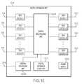
- FIG. 12is a block diagram of one embodiment of a digital expansion unit 124 of system 1200 .
- Digital expansion unit 124includes at least one digital input-output unit (DIOU) 1202 , at least one digital multiplexing unit (DMU) 1204 , at least one digital input-output unit (DIOU) 1206 , at least one central processing unit (CPU) 1208 , at least one digital expansion clock unit 1210 , and at least one power supply 1212 . It is understood that the DMU 1204 performs both multiplexing and demultiplexing functionality between the various upstream and downstream connections.
- the digital expansion unit 124communicates N-bit words of digitized spectrum between the master host unit 104 and at least one hybrid expansion unit 106 .
- Each DIOU 1202 (DIOU 1202 - 1 through DIOU 1202 -N) of the digital expansion unit 124operates to convert between optical signals received across a digital expansion communication link 126 and electrical signals processed within the digital expansion unit 124 .
- the converted signalsare passed from each DIOU 1202 to the DMU 1204 , where they are multiplexed together and output to at least one DIOU 1206 which converts the electrical signals to optical signals and outputs the optical signals to at least one hybrid expansion unit or another digital expansion unit for further distribution.
- each DIOU 1206converts optical signals received from a downstream hybrid expansion unit or digital expansion unit into electrical signals, which are passed onto the DMU 1204 .
- the DMU 1204takes the upstream signals and multiplexes them together and outputs them to at least one DIOU 1202 , which converts the electrical signals into optical signals and sends the optical signals across a digital expansion communication link 126 toward the master host unit.
- multiple digital expansion unitsare daisy chained for expansion in the digital domain.
- the CPU 1208is used to control each DMU 1204 .
- An input/output (I/O) line 1214 coupled to CPU 1208is used for network monitoring and maintenance.
- I/O line 1214is an Ethernet port used for external communication with the system.
- the DMU 1204extracts the digital master reference clock signal from any one digital data stream received at any one of the DIOU 1202 and DIOU 1206 and sends the digital master reference clock signal to the digital expansion clock unit 1210 .
- the digital expansion clock unit 1210then provides the digital master reference clock signal to other functions in the DMU that require a clock signal.
- Power supply 1212is used to power various components within digital expansion unit 124 .
- system 1100further includes additional service provider interface 102 - 3 and master host unit 104 - 3 .
- Master host unit 104 - 3is connected to service provider interface 102 - 3 with analog communication link 112 - 3 .
- Digital expansion unit 124is connected to master host unit 104 - 3 through digital communication link 114 - 5 .
- digital expansion unit 124includes DIOU 1202 - 1 and DIOU 1202 - 2 as shown in FIG. 12 .
- DIOU 1202 - 1is coupled with digital communication link 114 - 4
- DIOU 1202 - 2is coupled with digital communication link 114 - 5 .
- DIOU 1202 - 1 and DIOU 1202 - 2are coupled to DMU 1204 , which multiplexes and demultiplexes upstream and downstream signals together allowing various bands to be distributed from master host unit 104 - 1 and master host unit 104 - 3 through the analog remote antenna clusters 108 and the digital remote antenna units 110 .
- Other example systemsinclude greater or fewer service provider interfaces 102 , master host units 104 , hybrid expansion units 106 , analog remote antenna clusters 108 , digital remote antenna units 110 , and digital expansion units 124 .
- FIG. 13is a block diagram of another embodiment of a system 1300 for providing wireless coverage into a substantially enclosed environment.
- the system 1300includes some of the same components as system 1100 , including a first service provider interface 102 - 1 , a master host unit 104 - 1 , a hybrid expansion unit 106 - 1 , an analog remote antenna cluster 108 - 1 , an analog remote antenna cluster 108 - 2 , a digital expansion unit 124 , a digital remote antenna unit 110 - 6 , and a digital remote antenna unit 110 - 7 .
- system 1100also includes hybrid expansion unit 106 - 2 and analog remote antenna cluster 108 - 3 and 108 - 4 .
- Hybrid expansion unit 106 - 2is coupled to digital expansion unit 124 through digital expansion communication link 126 - 4 .
- Analog remote antenna cluster 108 - 3is connected to hybrid expansion unit 106 - 2 through analog communication link 118 - 3 and analog remote antenna cluster 108 - 4 is connected to hybrid expansion unit 106 - 2 through analog communication link 118 - 4 .
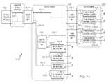
- FIG. 14is a block diagram of another embodiment of a system 1400 for providing wireless coverage into a substantially enclosed environment.
- the system 1400includes all of the same components as system 1300 and some additional components from system 900 , including service provider interface 102 - 1 , master host unit 104 - 1 , hybrid expansion unit 106 - 1 , hybrid expansion unit 106 - 2 , analog remote antenna cluster 108 - 1 , analog remote antenna cluster 108 - 2 , analog remote antenna cluster 108 - 3 , analog remote antenna cluster 108 - 4 , digital expansion unit 124 , digital remote antenna unit 110 - 1 , digital remote antenna unit 110 - 2 , digital remote antenna unit 110 - 6 , and digital remote antenna unit 110 - 7 .
- the various componentsincluding master host unit(s) 104 , hybrid expansion unit(s) 106 , analog remote antenna cluster(s) 108 , digital remote unit(s) 110 , and digital expansion unit(s) 124 , are shown as separate components. In some other example embodiments, some of these components can be combined into the same physical housing or structure and/or functionality can be ported from one component to another.
Landscapes
- Engineering & Computer Science (AREA)
- Computer Networks & Wireless Communication (AREA)
- Signal Processing (AREA)
- Mobile Radio Communication Systems (AREA)
- Transceivers (AREA)
- Selective Calling Equipment (AREA)
Abstract
Description
Claims (62)
Priority Applications (11)
| Application Number | Priority Date | Filing Date | Title |
|---|---|---|---|
| US12/913,179US8532242B2 (en) | 2010-10-27 | 2010-10-27 | Distributed antenna system with combination of both all digital transport and hybrid digital/analog transport |
| CN201610670195.XACN106301533B (en) | 2010-10-27 | 2011-10-25 | In conjunction with the distributing antenna system of digital transmission and digital-to-analog mixed transport |
| PCT/US2011/057575WO2012058182A1 (en) | 2010-10-27 | 2011-10-25 | Distributed antenna system with combination of both all digital transport and hybrid digital/analog transport |
| KR1020147017490AKR101729063B1 (en) | 2010-10-27 | 2011-10-25 | Distributed antenna system with combination of both all digital transport and hybrid digital/analog transport |
| EP19159426.6AEP3522395A1 (en) | 2010-10-27 | 2011-10-25 | Distributed antenna system |
| KR1020137013076AKR101460168B1 (en) | 2010-10-27 | 2011-10-25 | Distributed antenna system with combination of both all digital transport and hybrid digital/analog transport |
| CN201180063065.5ACN103299557B (en) | 2010-10-27 | 2011-10-25 | Distributed Antenna System Combining Full Digital Transmission and Digital/Analog Hybrid Transmission |
| EP11836933.9AEP2633634B1 (en) | 2010-10-27 | 2011-10-25 | Distributed antenna system with combination of both all digital transport and hybrid digital/analog transport |
| CA2815509ACA2815509C (en) | 2010-10-27 | 2011-10-25 | Distributed antenna system with combination of both all digital transport and hybrid digital/analog transport |
| US14/849,870USRE47160E1 (en) | 2010-10-27 | 2015-09-10 | Distributed antenna system with combination of both all digital transport and hybrid digital/analog transport |
| US16/215,391USRE48757E1 (en) | 2010-10-27 | 2018-12-10 | Distributed antenna system with combination of both all digital transport and hybrid digital/analog transport |
Applications Claiming Priority (1)
| Application Number | Priority Date | Filing Date | Title |
|---|---|---|---|
| US12/913,179US8532242B2 (en) | 2010-10-27 | 2010-10-27 | Distributed antenna system with combination of both all digital transport and hybrid digital/analog transport |
Related Parent Applications (1)
| Application Number | Title | Priority Date | Filing Date |
|---|---|---|---|
| US14/849,870ContinuationUSRE47160E1 (en) | 2010-10-27 | 2015-09-10 | Distributed antenna system with combination of both all digital transport and hybrid digital/analog transport |
Related Child Applications (2)
| Application Number | Title | Priority Date | Filing Date |
|---|---|---|---|
| US14/849,870ReissueUSRE47160E1 (en) | 2010-10-27 | 2015-09-10 | Distributed antenna system with combination of both all digital transport and hybrid digital/analog transport |
| US16/215,391ReissueUSRE48757E1 (en) | 2010-10-27 | 2018-12-10 | Distributed antenna system with combination of both all digital transport and hybrid digital/analog transport |
Publications (2)
| Publication Number | Publication Date |
|---|---|
| US20120106657A1 US20120106657A1 (en) | 2012-05-03 |
| US8532242B2true US8532242B2 (en) | 2013-09-10 |
Family
ID=45994350
Family Applications (3)
| Application Number | Title | Priority Date | Filing Date |
|---|---|---|---|
| US12/913,179CeasedUS8532242B2 (en) | 2010-10-27 | 2010-10-27 | Distributed antenna system with combination of both all digital transport and hybrid digital/analog transport |
| US14/849,870Active2032-01-17USRE47160E1 (en) | 2010-10-27 | 2015-09-10 | Distributed antenna system with combination of both all digital transport and hybrid digital/analog transport |
| US16/215,391Active2032-01-17USRE48757E1 (en) | 2010-10-27 | 2018-12-10 | Distributed antenna system with combination of both all digital transport and hybrid digital/analog transport |
Family Applications After (2)
| Application Number | Title | Priority Date | Filing Date |
|---|---|---|---|
| US14/849,870Active2032-01-17USRE47160E1 (en) | 2010-10-27 | 2015-09-10 | Distributed antenna system with combination of both all digital transport and hybrid digital/analog transport |
| US16/215,391Active2032-01-17USRE48757E1 (en) | 2010-10-27 | 2018-12-10 | Distributed antenna system with combination of both all digital transport and hybrid digital/analog transport |
Country Status (6)
| Country | Link |
|---|---|
| US (3) | US8532242B2 (en) |
| EP (2) | EP2633634B1 (en) |
| KR (2) | KR101460168B1 (en) |
| CN (2) | CN103299557B (en) |
| CA (1) | CA2815509C (en) |
| WO (1) | WO2012058182A1 (en) |
Cited By (60)
| Publication number | Priority date | Publication date | Assignee | Title |
|---|---|---|---|---|
| US20130107763A1 (en)* | 2011-10-28 | 2013-05-02 | Adc Telecommunications, Inc. | Distributed antenna system using time division duplexing scheme |
| US20150057039A1 (en)* | 2011-10-14 | 2015-02-26 | Qualcomm Incorporated | Distributed antenna systems and methods of wireless communications for facilitating simulcasting and de-simulcasting of downlink transmissions |
| US9037143B2 (en) | 2010-08-16 | 2015-05-19 | Corning Optical Communications LLC | Remote antenna clusters and related systems, components, and methods supporting digital data signal propagation between remote antenna units |
| US9042732B2 (en) | 2010-05-02 | 2015-05-26 | Corning Optical Communications LLC | Providing digital data services in optical fiber-based distributed radio frequency (RF) communication systems, and related components and methods |
| US9078218B1 (en) | 2014-03-27 | 2015-07-07 | Corning Optical Communications Wireless Ltd. | Gain measurement of distributed antenna system (DAS) segments during active communications employing autocorrelation on a combined test signal and communications signal |
| US9112611B2 (en) | 2009-02-03 | 2015-08-18 | Corning Optical Communications LLC | Optical fiber-based distributed antenna systems, components, and related methods for calibration thereof |
| US20150303998A1 (en)* | 2013-12-23 | 2015-10-22 | Dali Systems Co. Ltd. | Digital multiplexer in a distributed antenna system |
| US9178635B2 (en) | 2014-01-03 | 2015-11-03 | Corning Optical Communications Wireless Ltd | Separation of communication signal sub-bands in distributed antenna systems (DASs) to reduce interference |
| US9184843B2 (en) | 2011-04-29 | 2015-11-10 | Corning Optical Communications LLC | Determining propagation delay of communications in distributed antenna systems, and related components, systems, and methods |
| US9219879B2 (en) | 2009-11-13 | 2015-12-22 | Corning Optical Communications LLC | Radio-over-fiber (ROF) system for protocol-independent wired and/or wireless communication |
| US9240835B2 (en) | 2011-04-29 | 2016-01-19 | Corning Optical Communications LLC | Systems, methods, and devices for increasing radio frequency (RF) power in distributed antenna systems |
| US9247543B2 (en) | 2013-07-23 | 2016-01-26 | Corning Optical Communications Wireless Ltd | Monitoring non-supported wireless spectrum within coverage areas of distributed antenna systems (DASs) |
| US9253003B1 (en) | 2014-09-25 | 2016-02-02 | Corning Optical Communications Wireless Ltd | Frequency shifting a communications signal(S) in a multi-frequency distributed antenna system (DAS) to avoid or reduce frequency interference |
| US9312941B2 (en) | 2011-10-14 | 2016-04-12 | Qualcomm Incorporated | Base stations and methods for facilitating dynamic simulcasting and de-simulcasting in a distributed antenna system |
| US9319138B2 (en) | 2010-02-15 | 2016-04-19 | Corning Optical Communications LLC | Dynamic cell bonding (DCB) for radio-over-fiber (RoF)-based networks and communication systems and related methods |
| US9325429B2 (en) | 2011-02-21 | 2016-04-26 | Corning Optical Communications LLC | Providing digital data services as electrical signals and radio-frequency (RF) communications over optical fiber in distributed communications systems, and related components and methods |
| US9338823B2 (en) | 2012-03-23 | 2016-05-10 | Corning Optical Communications Wireless Ltd | Radio-frequency integrated circuit (RFIC) chip(s) for providing distributed antenna system functionalities, and related components, systems, and methods |
| US9357551B2 (en) | 2014-05-30 | 2016-05-31 | Corning Optical Communications Wireless Ltd | Systems and methods for simultaneous sampling of serial digital data streams from multiple analog-to-digital converters (ADCS), including in distributed antenna systems |
| US9385810B2 (en) | 2013-09-30 | 2016-07-05 | Corning Optical Communications Wireless Ltd | Connection mapping in distributed communication systems |
| US9420542B2 (en) | 2014-09-25 | 2016-08-16 | Corning Optical Communications Wireless Ltd | System-wide uplink band gain control in a distributed antenna system (DAS), based on per band gain control of remote uplink paths in remote units |
| US9455784B2 (en) | 2012-10-31 | 2016-09-27 | Corning Optical Communications Wireless Ltd | Deployable wireless infrastructures and methods of deploying wireless infrastructures |
| US9525488B2 (en) | 2010-05-02 | 2016-12-20 | Corning Optical Communications LLC | Digital data services and/or power distribution in optical fiber-based distributed communications systems providing digital data and radio frequency (RF) communications services, and related components and methods |
| US20160373232A1 (en)* | 2012-11-26 | 2016-12-22 | Commscope Technologies Llc | Timeslot mapping and/or aggregation element for digital radio frequency transport architecture |
| US9602210B2 (en) | 2014-09-24 | 2017-03-21 | Corning Optical Communications Wireless Ltd | Flexible head-end chassis supporting automatic identification and interconnection of radio interface modules and optical interface modules in an optical fiber-based distributed antenna system (DAS) |
| US9621293B2 (en) | 2012-08-07 | 2017-04-11 | Corning Optical Communications Wireless Ltd | Distribution of time-division multiplexed (TDM) management services in a distributed antenna system, and related components, systems, and methods |
| US9647758B2 (en) | 2012-11-30 | 2017-05-09 | Corning Optical Communications Wireless Ltd | Cabling connectivity monitoring and verification |
| US9661781B2 (en) | 2013-07-31 | 2017-05-23 | Corning Optical Communications Wireless Ltd | Remote units for distributed communication systems and related installation methods and apparatuses |
| US9673904B2 (en) | 2009-02-03 | 2017-06-06 | Corning Optical Communications LLC | Optical fiber-based distributed antenna systems, components, and related methods for calibration thereof |
| US9681313B2 (en) | 2015-04-15 | 2017-06-13 | Corning Optical Communications Wireless Ltd | Optimizing remote antenna unit performance using an alternative data channel |
| US9715157B2 (en) | 2013-06-12 | 2017-07-25 | Corning Optical Communications Wireless Ltd | Voltage controlled optical directional coupler |
| US9730228B2 (en) | 2014-08-29 | 2017-08-08 | Corning Optical Communications Wireless Ltd | Individualized gain control of remote uplink band paths in a remote unit in a distributed antenna system (DAS), based on combined uplink power level in the remote unit |
| US20170230101A1 (en)* | 2014-08-12 | 2017-08-10 | Kathrein-Werke Kg | Method and system for relaying telecommunications signals |
| US9775123B2 (en) | 2014-03-28 | 2017-09-26 | Corning Optical Communications Wireless Ltd. | Individualized gain control of uplink paths in remote units in a distributed antenna system (DAS) based on individual remote unit contribution to combined uplink power |
| US9807700B2 (en) | 2015-02-19 | 2017-10-31 | Corning Optical Communications Wireless Ltd | Offsetting unwanted downlink interference signals in an uplink path in a distributed antenna system (DAS) |
| US9813229B2 (en) | 2007-10-22 | 2017-11-07 | Corning Optical Communications Wireless Ltd | Communication system using low bandwidth wires |
| US9948349B2 (en) | 2015-07-17 | 2018-04-17 | Corning Optical Communications Wireless Ltd | IOT automation and data collection system |
| US9974074B2 (en) | 2013-06-12 | 2018-05-15 | Corning Optical Communications Wireless Ltd | Time-division duplexing (TDD) in distributed communications systems, including distributed antenna systems (DASs) |
| US10080178B2 (en) | 2006-12-26 | 2018-09-18 | Dali Wireless, Inc. | Distributed antenna system |
| US10096909B2 (en) | 2014-11-03 | 2018-10-09 | Corning Optical Communications Wireless Ltd. | Multi-band monopole planar antennas configured to facilitate improved radio frequency (RF) isolation in multiple-input multiple-output (MIMO) antenna arrangement |
| US10110308B2 (en) | 2014-12-18 | 2018-10-23 | Corning Optical Communications Wireless Ltd | Digital interface modules (DIMs) for flexibly distributing digital and/or analog communications signals in wide-area analog distributed antenna systems (DASs) |
| US10128951B2 (en) | 2009-02-03 | 2018-11-13 | Corning Optical Communications LLC | Optical fiber-based distributed antenna systems, components, and related methods for monitoring and configuring thereof |
| US10136200B2 (en) | 2012-04-25 | 2018-11-20 | Corning Optical Communications LLC | Distributed antenna system architectures |
| US10135533B2 (en) | 2014-11-13 | 2018-11-20 | Corning Optical Communications Wireless Ltd | Analog distributed antenna systems (DASS) supporting distribution of digital communications signals interfaced from a digital signal source and analog radio frequency (RF) communications signals |
| US10159074B2 (en) | 2010-09-14 | 2018-12-18 | Dali Wireless, Inc. | Remotely reconfigurable distributed antenna system and methods |
| US10187151B2 (en) | 2014-12-18 | 2019-01-22 | Corning Optical Communications Wireless Ltd | Digital-analog interface modules (DAIMs) for flexibly distributing digital and/or analog communications signals in wide-area analog distributed antenna systems (DASs) |
| US20190082243A1 (en)* | 2012-01-31 | 2019-03-14 | Dali Systems Co. Ltd. | Data transport in a virtualized distributed antenna system |
| US10236924B2 (en) | 2016-03-31 | 2019-03-19 | Corning Optical Communications Wireless Ltd | Reducing out-of-channel noise in a wireless distribution system (WDS) |
| US10499269B2 (en) | 2015-11-12 | 2019-12-03 | Commscope Technologies Llc | Systems and methods for assigning controlled nodes to channel interfaces of a controller |
| US10560214B2 (en) | 2015-09-28 | 2020-02-11 | Corning Optical Communications LLC | Downlink and uplink communication path switching in a time-division duplex (TDD) distributed antenna system (DAS) |
| US10659163B2 (en) | 2014-09-25 | 2020-05-19 | Corning Optical Communications LLC | Supporting analog remote antenna units (RAUs) in digital distributed antenna systems (DASs) using analog RAU digital adaptors |
| US10819477B2 (en) | 2016-10-07 | 2020-10-27 | Corning Optical Communications LLC | Digital wireless distributed communications system (WDCS) employing a centralized spectrum chunk construction of communications channels for distribution to remote units to reduce transmission data rates |
| USRE48342E1 (en) | 2010-07-28 | 2020-12-01 | Commscope Technologies Llc | Distributed digital reference clock |
| US10931377B2 (en) | 2012-02-28 | 2021-02-23 | Dali Systems Co. Ltd. | Hybrid data transport for a virtualized distributed antenna system |
| USRE48757E1 (en) | 2010-10-27 | 2021-09-28 | Commscope Technologies Llc | Distributed antenna system with combination of both all digital transport and hybrid digital/analog transport |
| US11159129B2 (en) | 2002-05-01 | 2021-10-26 | Dali Wireless, Inc. | Power amplifier time-delay invariant predistortion methods and apparatus |
| US11178609B2 (en) | 2010-10-13 | 2021-11-16 | Corning Optical Communications LLC | Power management for remote antenna units in distributed antenna systems |
| US11297603B2 (en) | 2010-08-17 | 2022-04-05 | Dali Wireless, Inc. | Neutral host architecture for a distributed antenna system |
| US11418155B2 (en) | 2002-05-01 | 2022-08-16 | Dali Wireless, Inc. | Digital hybrid mode power amplifier system |
| US11564110B2 (en) | 2011-11-07 | 2023-01-24 | Dali Wireless, Inc. | Soft hand-off and routing data in a virtualized distributed antenna system |
| US11563492B2 (en) | 2013-12-23 | 2023-01-24 | Dali Wireless, Inc. | Virtual radio access network using software-defined network of remotes and digital multiplexing switches |
Families Citing this family (23)
| Publication number | Priority date | Publication date | Assignee | Title |
|---|---|---|---|---|
| US8346091B2 (en)* | 2009-04-29 | 2013-01-01 | Andrew Llc | Distributed antenna system for wireless network systems |
| ES2399650B1 (en)* | 2010-11-29 | 2014-02-11 | Telefónica, S.A. | SYSTEM FOR THE INTERIOR DISTRIBUTION OF SIGNS ON FIBER OPTICS |
| US8462683B2 (en)* | 2011-01-12 | 2013-06-11 | Adc Telecommunications, Inc. | Distinct transport path for MIMO transmissions in distributed antenna systems |
| DE202013012858U1 (en) | 2012-08-09 | 2021-05-07 | Axel Wireless Ltd. | Capacity-centered digital distributed antenna system |
| US9750082B2 (en)* | 2013-10-07 | 2017-08-29 | Commscope Technologies Llc | Systems and methods for noise floor optimization in distributed antenna system with direct digital interface to base station |
| US9787457B2 (en)* | 2013-10-07 | 2017-10-10 | Commscope Technologies Llc | Systems and methods for integrating asynchronous signals in distributed antenna system with direct digital interface to base station |
| US9813266B2 (en)* | 2014-07-28 | 2017-11-07 | Benjamin Kim | Distributed combined junctional transformer |
| GB2529185B (en) | 2014-08-12 | 2021-03-03 | Kathrein Se | Method and system for relaying telecommunications signals wtih efficient joint capacity |
| CA2961696A1 (en) | 2014-09-23 | 2016-03-31 | Axell Wireless Ltd. | Automatic mapping and handling pim and other uplink interferences in digital distributed antenna systems |
| KR102233680B1 (en) | 2014-09-30 | 2021-03-30 | 한국전자통신연구원 | Central office device, remote site device, and communication method thoseof |
| WO2016098101A1 (en)* | 2014-12-18 | 2016-06-23 | Corning Optical Communications Wireless Ltd. | Distributing digital communications signals in analog distributed antenna systems (dass) using programmable head-end units |
| EP3238352A4 (en) | 2014-12-23 | 2018-08-22 | Axell Wireless Ltd. | Harmonizing noise aggregation and noise management in distributed antenna system |
| KR20160081122A (en)* | 2014-12-30 | 2016-07-08 | 주식회사 쏠리드 | Distributed antenna system for multiple-input multiple-output signal |
| KR102165085B1 (en)* | 2015-04-30 | 2020-10-13 | 주식회사 쏠리드 | Satellite signal relay system |
| KR101791636B1 (en)* | 2016-03-28 | 2017-10-30 | 주식회사 쏠리드 | Base station signal matching device, base station interface unit and distributed antenna system comprising the same |
| US10932261B2 (en)* | 2016-05-05 | 2021-02-23 | Huawei Technologies Co., Ltd. | Multi-band transmitter system incorporating a multi-band synthesizer |
| EP3252490B1 (en)* | 2016-06-03 | 2020-09-16 | Siemens Healthcare GmbH | Device and method for transporting radiofrequency-signals through a shielded, balanced line |
| US10904818B2 (en)* | 2017-02-15 | 2021-01-26 | Maven Wireless Sweden Ab | Distributed antenna system providing redundancy |
| KR102408468B1 (en)* | 2017-02-21 | 2022-06-14 | 메이븐 와이어리스 스웨덴 에이비 | Distributed Antenna Systems for Multi-Operator Networks |
| US10819568B2 (en) | 2017-06-26 | 2020-10-27 | Commscope Technologies Llc | System and method for configuring the ethernet network and RF connections for links between nodes of a distributed antenna system |
| KR102398387B1 (en)* | 2017-09-18 | 2022-05-16 | 프라운호퍼 게젤샤프트 쭈르 푀르데룽 데어 안겐반텐 포르슝 에. 베. | Reliable, low-latency transmission method of data over voice channels in telecommunication networks |
| US10805811B2 (en)* | 2017-12-18 | 2020-10-13 | Commscope Technologies Llc | Synchronization and fault management in a distributed antenna system |
| EP4016851B1 (en)* | 2020-12-18 | 2023-06-21 | Nxp B.V. | A system comprising multiple units |
Citations (114)
| Publication number | Priority date | Publication date | Assignee | Title |
|---|---|---|---|---|
| US4183054A (en) | 1977-09-30 | 1980-01-08 | Harris Corporation | Digital, frequency-translated, plural-channel, vestigial sideband television communication system |
| US4451916A (en) | 1980-05-12 | 1984-05-29 | Harris Corporation | Repeatered, multi-channel fiber optic communication network having fault isolation system |
| US4611323A (en) | 1983-05-24 | 1986-09-09 | Ant Nachrichtentechnik Gmbh | Method for transmitting digitally coded analog signals |
| US4628501A (en) | 1983-12-29 | 1986-12-09 | The United States Of America As Represented By The Secretary Of The Army | Optical communications systems |
| US4654843A (en) | 1982-09-17 | 1987-03-31 | U.S. Philips Corporation | Signal distribution system |
| US4691292A (en) | 1983-04-13 | 1987-09-01 | Rca Corporation | System for digital multiband filtering |
| US4999831A (en) | 1989-10-19 | 1991-03-12 | United Telecommunications, Inc. | Synchronous quantized subcarrier multiplexer for digital transport of video, voice and data |
| EP0391597A3 (en) | 1989-04-04 | 1992-01-08 | AT&T Corp. | Optical fiber microcellular mobile radio |
| US5193109A (en) | 1989-02-06 | 1993-03-09 | Pactel Corporation | Zoned microcell with sector scanning for cellular telephone system |
| CA2069462A1 (en) | 1992-01-09 | 1993-07-10 | Andrew S. Beasley | Rf repeater arrangement with reduced noise for wireless telephones |
| US5243598A (en) | 1991-04-02 | 1993-09-07 | Pactel Corporation | Microcell system in digital cellular |
| CA2138763A1 (en) | 1992-07-14 | 1994-01-20 | Andrew Beasley | Rf repeaters for time division duplex cordless telephone system |
| US5303287A (en) | 1992-08-13 | 1994-04-12 | Hughes Aircraft Company | Integrated personal/cellular communications system architecture |
| US5321849A (en) | 1991-05-22 | 1994-06-14 | Southwestern Bell Technology Resources, Inc. | System for controlling signal level at both ends of a transmission link based on a detected valve |
| US5321736A (en) | 1992-01-03 | 1994-06-14 | Pcs Microcell International Inc. | Distributed RF repeater arrangement for cordless telephones |
| US5339184A (en) | 1992-06-15 | 1994-08-16 | Gte Laboratories Incorporated | Fiber optic antenna remoting for multi-sector cell sites |
| CA2156046A1 (en) | 1993-06-23 | 1995-01-05 | Andrew Beasley | Cordless telephone system and zone switching control method |
| US5381459A (en) | 1991-07-29 | 1995-01-10 | Cable Television Laboratories, Inc. | System for distributing radio telephone signals over a cable television network |
| US5400391A (en) | 1990-09-17 | 1995-03-21 | Nec Corporation | Mobile communication system |
| US5461627A (en) | 1991-12-24 | 1995-10-24 | Rypinski; Chandos A. | Access protocol for a common channel wireless network |
| GB2289198B (en) | 1991-01-15 | 1996-01-10 | Rogers Cantel Inc | A remote antenna driver |
| CA2128842A1 (en) | 1994-07-26 | 1996-01-27 | Andrew Beasley | Wireless telephone systememploying switchboard-controlled lines |
| US5519691A (en) | 1994-06-03 | 1996-05-21 | At&T Corp. | Arrangement for and method of providing radio frequency access to a switching system |
| US5545397A (en) | 1991-10-23 | 1996-08-13 | Boron Biologicals, Inc. | Contrast agents and compositions for radiological imaging, and radiological imaging method utilizing same |
| US5566168A (en) | 1994-01-11 | 1996-10-15 | Ericsson Ge Mobile Communications Inc. | TDMA/FDMA/CDMA hybrid radio access methods |
| CA2158386A1 (en) | 1995-09-15 | 1997-03-16 | Andrew Beasley | Rf repeaters for tdma mobile telephone systems |
| CA2058737C (en) | 1992-01-03 | 1997-03-18 | Andrew S. Beasley | Rf repeater arrangement with improved frequency reuse for wireless telephones |
| US5621786A (en) | 1992-09-17 | 1997-04-15 | Adc Telecomminications, Inc. | Cellular communications system having passive handoff |
| US5634191A (en) | 1994-10-24 | 1997-05-27 | Pcs Microcell International, Inc. | Self-adjusting RF repeater arrangements for wireless telephone systems |
| CA2168681A1 (en) | 1996-02-02 | 1997-08-03 | Andrew Beasley | Rf repeaters for time division cordless telephone systems without timing signals |
| US5682256A (en) | 1988-11-11 | 1997-10-28 | British Telecommunications Public Limited Company | Communications system |
| US5687195A (en) | 1994-12-16 | 1997-11-11 | Electronics And Telecommunications Research Institute | Digital automatic gain controller for satellite transponder |
| US5732076A (en) | 1995-10-26 | 1998-03-24 | Omnipoint Corporation | Coexisting communication systems |
| US5761619A (en) | 1995-03-23 | 1998-06-02 | Telefoanktiebolaget Lm Ericsson | Distributed telecommunications system |
| US5765099A (en) | 1996-04-19 | 1998-06-09 | Georges; John B. | Distribution of radio-frequency signals through low bandwidth infrastructures |
| GB2320653A (en) | 1996-12-23 | 1998-06-24 | Northern Telecom Ltd | Mobile Communications Network Using Alternative Protocols |
| US5781541A (en) | 1995-05-03 | 1998-07-14 | Bell Atlantic Network Services, Inc. | CDMA system having time-distributed transmission paths for multipath reception |
| US5802173A (en) | 1991-01-15 | 1998-09-01 | Rogers Cable Systems Limited | Radiotelephony system |
| US5805983A (en) | 1996-07-18 | 1998-09-08 | Ericsson Inc. | System and method for equalizing the delay time for transmission paths in a distributed antenna network |
| US5809395A (en) | 1991-01-15 | 1998-09-15 | Rogers Cable Systems Limited | Remote antenna driver for a radio telephony system |
| US5822324A (en) | 1995-03-16 | 1998-10-13 | Bell Atlantic Network Services, Inc. | Simulcasting digital video programs for broadcast and interactive services |
| US5845199A (en) | 1996-12-05 | 1998-12-01 | Ericsson Inc. | Simulcasting system with diversity reception |
| US5867485A (en) | 1996-06-14 | 1999-02-02 | Bellsouth Corporation | Low power microcellular wireless drop interactive network |
| US5870392A (en) | 1995-12-28 | 1999-02-09 | Lucent Technologies Inc. | Microcell architecture |
| CA2215079A1 (en) | 1997-09-09 | 1999-03-09 | Andrew S. Beasley | Wireless loop system with enhanced access |
| US5890055A (en) | 1995-07-28 | 1999-03-30 | Lucent Technologies Inc. | Method and system for connecting cells and microcells in a wireless communications network |
| US5907544A (en) | 1996-05-10 | 1999-05-25 | Rypinski; Chandos A. | Hub controller architecture and function for a multiple access-point wireless communication network |
| US5987014A (en) | 1994-07-14 | 1999-11-16 | Stanford Telecommunications, Inc. | Multipath resistant, orthogonal code-division multiple access system |
| US6023628A (en) | 1992-08-05 | 2000-02-08 | Pcs Wireless, Inc. | Base stations for TDD telephony and methods for operating the same |
| EP0876073A3 (en) | 1997-05-01 | 2000-03-01 | AT&T Corp. | Dual-mode telephone for cordless and cellular networks |
| US6034950A (en) | 1996-12-27 | 2000-03-07 | Motorola Inc. | System packet-based centralized base station controller |
| US6108113A (en) | 1995-12-29 | 2000-08-22 | Mci Communications Corporation | Method and system for transporting ancillary network data |
| US6108626A (en) | 1995-10-27 | 2000-08-22 | Cselt-Centro Studi E Laboratori Telecomunicazioni S.P.A. | Object oriented audio coding |
| US6108550A (en) | 1997-06-13 | 2000-08-22 | Telefonaktienbolaget Lm Ericsson | Reuse of a physical control channel in a distributed cellular radio communication system |
| CA2134365C (en) | 1994-10-26 | 2000-10-03 | Andrew Beasley | Self-adjusting rf repeater arrangements for wireless telephone systems |
| JP2000333240A (en) | 2000-03-24 | 2000-11-30 | Kokusai Electric Co Ltd | Optical transmission system for mobile communication |
| US6157810A (en) | 1996-04-19 | 2000-12-05 | Lgc Wireless, Inc | Distribution of radio-frequency signals through low bandwidth infrastructures |
| US6157659A (en) | 1997-12-19 | 2000-12-05 | Nortel Networks Corporation | Method of and apparatus for multiplexing and demultiplexing digital signal streams |
| US6188693B1 (en) | 1996-02-14 | 2001-02-13 | Hitachi, Ltd. | ATM multiplexing apparatus, ATM demultiplexing apparatus, and communication network with the apparatus |
| GB2315959B (en) | 1996-08-01 | 2001-02-21 | Motorola Inc | Communications network node with switched channelizer architecture |
| US6222660B1 (en) | 1998-06-09 | 2001-04-24 | Tektronix, Inc. | Adaptive power supply for avalanche photodiode |
| US6226274B1 (en) | 1998-09-24 | 2001-05-01 | Omnipoint Corporation | Method and apparatus for multiple access communication |
| US6246675B1 (en) | 1995-11-14 | 2001-06-12 | Andrew Beasley | CDMA cordless telephone system and method of operation thereof |
| JP2001197012A (en) | 1999-10-27 | 2001-07-19 | Toyo Commun Equip Co Ltd | Optical transmission repeater and repeating system using same |
| US20010036163A1 (en) | 2000-03-27 | 2001-11-01 | Transcept Opencell, Inc. | Multi-protocol distributed wireless system architecture |
| US20010044292A1 (en) | 1999-12-22 | 2001-11-22 | Hyundai Electronics Industries Co., Ltd. | RF block of mobile communication base station |
| US6373887B1 (en) | 1998-06-30 | 2002-04-16 | Cisco Technology, Inc. | HTU-C clocking from a single source |
| US6377640B2 (en) | 1997-07-31 | 2002-04-23 | Stanford Syncom, Inc. | Means and method for a synchronous network communications system |
| US20020142739A1 (en) | 2001-03-27 | 2002-10-03 | Smith Andrew D. | Multi-channel peak power smoothing |
| US20020167954A1 (en) | 2001-05-11 | 2002-11-14 | P-Com, Inc. | Point-to-multipoint access network integrated with a backbone network |
| US20020191565A1 (en) | 2001-06-08 | 2002-12-19 | Sanjay Mani | Methods and systems employing receive diversity in distributed cellular antenna applications |
| US6498936B1 (en) | 1999-01-22 | 2002-12-24 | Ericsson Inc. | Methods and systems for coding of broadcast messages |
| US20030015943A1 (en) | 2001-06-28 | 2003-01-23 | Jong-Sun Kim | Rosen type piezoelectric transformer with multiple output electrodes, and stabilizer for multiple light source using that |
| JP2003023396A (en) | 2001-07-06 | 2003-01-24 | Hitachi Kokusai Electric Inc | Optical transmission equipment for mobile communication |
| US20030043928A1 (en) | 2001-02-01 | 2003-03-06 | Fuyun Ling | Coding scheme for a wireless communication system |
| US6567473B1 (en) | 1999-03-12 | 2003-05-20 | Aware, Inc. | Method for seamlessly changing power modes in a ADSL system |
| US20030203717A1 (en) | 1998-04-27 | 2003-10-30 | Chuprun Jeffery Scott | Satellite based data transfer and delivery system |
| US6667973B1 (en) | 1998-04-29 | 2003-12-23 | Zhone Technologies, Inc. | Flexible SONET access and transmission systems |
| US6674966B1 (en) | 1998-10-15 | 2004-01-06 | Lucent Technologies Inc. | Re-configurable fibre wireless network |
| US20040010609A1 (en) | 2000-02-08 | 2004-01-15 | Vilander Harri Tapani | Using internet protocol (IP) in radio access network |
| US20040032354A1 (en) | 2002-08-16 | 2004-02-19 | Yaron Knobel | Multi-band ultra-wide band communication method and system |
| US20040037565A1 (en) | 2002-08-22 | 2004-02-26 | Robin Young | Transport of signals over an optical fiber using analog RF multiplexing |
| US6704545B1 (en)* | 2000-07-19 | 2004-03-09 | Adc Telecommunications, Inc. | Point-to-multipoint digital radio frequency transport |
| US20040053602A1 (en) | 2002-09-18 | 2004-03-18 | Wurzburg Francis L. | Low-cost interoperable wireless multi-application and messaging service |
| US6729929B1 (en) | 1999-03-17 | 2004-05-04 | Cisco Systems, Inc. | Method and apparatus for controlling wireless networks |
| US20040106387A1 (en) | 2002-12-03 | 2004-06-03 | Adc Telecommunications, Inc. | Small signal threshold and proportional gain distributed digital communications |
| US20040106435A1 (en) | 2002-12-03 | 2004-06-03 | Adc Telecommunications, Inc. | Distributed digital antenna system |
| JP2004180220A (en) | 2002-11-29 | 2004-06-24 | Hitachi Kokusai Electric Inc | Radio station system |
| JP2004194351A (en) | 1999-02-05 | 2004-07-08 | Interdigital Technol Corp | Base station equipped with automatic cable loss compensation means |
| US6768745B1 (en) | 1998-04-29 | 2004-07-27 | Zhone Technologies, Inc. | Flexible SONET access and transmission system |
| US6785558B1 (en) | 2002-12-06 | 2004-08-31 | Lgc Wireless, Inc. | System and method for distributing wireless communication signals over metropolitan telecommunication networks |
| US20040198453A1 (en) | 2002-09-20 | 2004-10-07 | David Cutrer | Distributed wireless network employing utility poles and optical signal distribution |
| US20040203703A1 (en) | 2002-03-11 | 2004-10-14 | Fischer Larry G. | Distribution of wireless telephony and data signals in a substantially closed environment |
| US20040203339A1 (en) | 2002-12-03 | 2004-10-14 | Bauman Donald R. | Distributed signal summation and gain control |
| US20040219950A1 (en) | 2003-05-02 | 2004-11-04 | Jorma Pallonen | Antenna arrangement and base transceiver station |
| US6826163B2 (en) | 2001-06-08 | 2004-11-30 | Nextg Networks | Method and apparatus for multiplexing in a wireless communication infrastructure |
| US6826164B2 (en) | 2001-06-08 | 2004-11-30 | Nextg Networks | Method and apparatus for multiplexing in a wireless communication infrastructure |
| US6831901B2 (en) | 2002-05-31 | 2004-12-14 | Opencell Corporation | System and method for retransmission of data |
| US6865390B2 (en) | 2001-06-25 | 2005-03-08 | Lucent Technologies Inc. | Cellular communications system featuring a central radio pool/traffic router |
| US6917614B1 (en) | 1999-09-17 | 2005-07-12 | Arris International, Inc. | Multi-channel support for virtual private networks in a packet to ATM cell cable system |
| US20050250503A1 (en) | 2004-05-05 | 2005-11-10 | Cutrer David M | Wireless networks frequency reuse distance reduction |
| EP1214809B1 (en) | 1999-08-31 | 2006-03-01 | Motorola, Inc. | Method and system for measuring and adjusting the quality of an orthogonal transmit diversity signal |
| US20060066484A1 (en) | 2002-08-14 | 2006-03-30 | Skipper Wireless Inc. | Method and system for determining direction of transmission using multi-facet antenna |
| US20060094470A1 (en)* | 2004-11-01 | 2006-05-04 | Microwave Photonics, Inc. | Communications system and method |
| US20060121944A1 (en) | 2002-12-24 | 2006-06-08 | Flavio Buscaglia | Radio base station receiver having digital filtering and reduced sampling frequency |
| US20060153070A1 (en) | 2004-04-05 | 2006-07-13 | Delregno Nick | System and method for monitoring, controlling and provisioning a telecommunications access network |
| US20060172775A1 (en) | 2005-02-01 | 2006-08-03 | Adc Telecommunications, Inc. | Scalable distributed radio network |
| US20060193295A1 (en) | 2004-11-19 | 2006-08-31 | White Patrick E | Multi-access terminal with capability for simultaneous connectivity to multiple communication channels |
| US7127175B2 (en) | 2001-06-08 | 2006-10-24 | Nextg Networks | Method and apparatus for multiplexing in a wireless communication infrastructure |
| US20070008939A1 (en) | 2005-06-10 | 2007-01-11 | Adc Telecommunications, Inc. | Providing wireless coverage into substantially closed environments |
| US7205864B2 (en) | 2004-11-02 | 2007-04-17 | Nextg Networks, Inc. | Distributed matrix switch |
| US7289972B2 (en) | 2004-06-25 | 2007-10-30 | Virginia Tech Intellectual Properties, Inc. | Cognitive radio engine based on genetic algorithms in a network |
| US7733901B2 (en) | 1999-02-05 | 2010-06-08 | Tecore | Multi-protocol wireless communication apparatus and method |
| US20120027145A1 (en) | 2010-07-28 | 2012-02-02 | Adc Telecommunications, Inc. | Distributed digital reference clock |
Family Cites Families (48)
| Publication number | Priority date | Publication date | Assignee | Title |
|---|---|---|---|---|
| GB9008162D0 (en) | 1990-04-10 | 1990-06-06 | British Telecomm | Signal distribution |
| US5513176A (en) | 1990-12-07 | 1996-04-30 | Qualcomm Incorporated | Dual distributed antenna system |
| US5404570A (en) | 1992-11-23 | 1995-04-04 | Telefonaktiebolaget L M Ericsson | Radio coverage in closed environments |
| CA2191721C (en) | 1994-06-01 | 2003-05-20 | Ronald R. Carney | Wideband wireless basestation making use of time division multiple-access bus to effect switchable connections to modulator/demodulator resources |
| US5592480A (en) | 1995-03-13 | 1997-01-07 | Carney; Ronald R. | Wideband wireless basestation making use of time division multiple-access bus having selectable number of time slots and frame synchronization to support different modulation standards |
| US5970410A (en) | 1996-02-27 | 1999-10-19 | Airnet Communications Corp. | Cellular system plan using in band-translators to enable efficient deployment of high capacity base transceiver systems |
| US5914963A (en) | 1996-06-21 | 1999-06-22 | Compaq Computer Corporation | Clock skew reduction |
| US6205133B1 (en) | 1996-11-25 | 2001-03-20 | Ericsson Inc. | Flexible wideband architecture for use in radio communications systems |
| EP1060570A1 (en) | 1998-01-15 | 2000-12-20 | Interwave Communications Inc. | Wireless co-tenant base station |
| EP0935385A3 (en)* | 1998-02-04 | 2002-06-19 | Hitachi, Ltd. | Decoder device and receiver using the same |
| US6807374B1 (en) | 1999-05-14 | 2004-10-19 | Kokusai Electric Co., Ltd. | Mobile communication system |
| US6757553B1 (en)* | 1999-10-14 | 2004-06-29 | Qualcomm Incorporated | Base station beam sweeping method and apparatus using multiple rotating antennas |
| AU2001255819A1 (en) | 2000-03-29 | 2001-10-08 | Transcept Opencell, Inc. | Operations and maintenance architecture for multiprotocol distributed system |
| CN1426664A (en) | 2000-04-25 | 2003-06-25 | 高通股份有限公司 | Radio frequency coverage of enclosed regions |
| GB2370170B (en) | 2000-12-15 | 2003-01-29 | Ntl Group Ltd | Signal transmission systems |
| US6801767B1 (en)* | 2001-01-26 | 2004-10-05 | Lgc Wireless, Inc. | Method and system for distributing multiband wireless communications signals |
| US20030157943A1 (en)* | 2002-01-29 | 2003-08-21 | John Sabat | Method and apparatus for auxiliary pilot signal for mobile phone location |
| US7706295B2 (en) | 2003-09-09 | 2010-04-27 | Marvell Semiconductor, Inc. | Methods and apparatus for breaking and resynchronizing a data link |
| US20060026017A1 (en) | 2003-10-28 | 2006-02-02 | Walker Richard C | National / international management and security system for responsible global resourcing through technical management to brige cultural and economic desparity |
| US7474852B1 (en) | 2004-02-12 | 2009-01-06 | Multidyne Electronics Inc. | System for communication of video, audio, data, control or other signals over fiber |
| CN100446453C (en)* | 2005-07-19 | 2008-12-24 | 电子科技大学 | A communication method for a distributed multiple-input multiple-output orthogonal frequency division multiplexing communication system |
| US20070274279A1 (en) | 2005-12-19 | 2007-11-29 | Wood Steven A | Distributed antenna system employing digital forward deployment of wireless transmit/receive locations |
| US8873585B2 (en)* | 2006-12-19 | 2014-10-28 | Corning Optical Communications Wireless Ltd | Distributed antenna system for MIMO technologies |
| US8737454B2 (en)* | 2007-01-25 | 2014-05-27 | Adc Telecommunications, Inc. | Modular wireless communications platform |
| US8014577B2 (en) | 2007-01-29 | 2011-09-06 | Institut National D'optique | Micro-array analysis system and method thereof |
| WO2008099383A2 (en) | 2007-02-12 | 2008-08-21 | Mobileaccess Networks Ltd. | Mimo-adapted distributed antenna system |
| US7668153B2 (en)* | 2007-03-27 | 2010-02-23 | Adc Telecommunications, Inc. | Method for data converter sample clock distribution |
| US8149811B2 (en)* | 2007-07-18 | 2012-04-03 | Marvell World Trade Ltd. | Wireless network with simultaneous uplink transmission of independent data from multiple client stations |
| CN101355778B (en)* | 2007-07-27 | 2012-05-23 | 中兴通讯股份有限公司 | Single frequency network system, working method and mobile communication system superposed with single frequency network |
| US8325637B2 (en) | 2007-07-31 | 2012-12-04 | Johnson Controls Technology Company | Pairing wireless devices of a network using relative gain arrays |
| US9112547B2 (en) | 2007-08-31 | 2015-08-18 | Adc Telecommunications, Inc. | System for and method of configuring distributed antenna communications system |
| US8175649B2 (en) | 2008-06-20 | 2012-05-08 | Corning Mobileaccess Ltd | Method and system for real time control of an active antenna over a distributed antenna system |
| US8195224B2 (en) | 2008-05-13 | 2012-06-05 | Corning Mobileaccess Ltd | Multiple data services over a distributed antenna system |
| US8165100B2 (en)* | 2007-12-21 | 2012-04-24 | Powerwave Technologies, Inc. | Time division duplexed digital distributed antenna system |
| TW200937897A (en)* | 2008-02-19 | 2009-09-01 | Wistron Neweb Corp | Embedded multimedia system and related digital audio broadcasting demodulator |
| US8005152B2 (en) | 2008-05-21 | 2011-08-23 | Samplify Systems, Inc. | Compression of baseband signals in base transceiver systems |
| US8385373B2 (en)* | 2008-06-24 | 2013-02-26 | Adc Telecommunications, Inc. | Method and apparatus for frame detection in a communications system |
| US8208414B2 (en) | 2008-06-24 | 2012-06-26 | Lgc Wireless, Inc. | System and method for configurable time-division duplex interface |
| KR100968926B1 (en)* | 2008-07-24 | 2010-07-14 | 알트론 주식회사 | Multiband Optical Repeater System in Mobile Communication Networks |
| US8774084B2 (en) | 2008-08-22 | 2014-07-08 | Qualcomm Incorporated | Base station synchronization |
| KR101024574B1 (en)* | 2008-12-31 | 2011-03-31 | 주식회사 포스코아이씨티 | Base station and base station system using the same |
| US8428510B2 (en)* | 2010-03-25 | 2013-04-23 | Adc Telecommunications, Inc. | Automatic gain control configuration for a wideband distributed antenna system |
| US8681917B2 (en) | 2010-03-31 | 2014-03-25 | Andrew Llc | Synchronous transfer of streaming data in a distributed antenna system |
| US8532242B2 (en) | 2010-10-27 | 2013-09-10 | Adc Telecommunications, Inc. | Distributed antenna system with combination of both all digital transport and hybrid digital/analog transport |
| US8462683B2 (en)* | 2011-01-12 | 2013-06-11 | Adc Telecommunications, Inc. | Distinct transport path for MIMO transmissions in distributed antenna systems |
| CN103733664B (en) | 2011-07-11 | 2017-10-24 | 康普技术有限责任公司 | Method and apparatus for managing a distributed antenna system |
| US8693342B2 (en)* | 2011-10-28 | 2014-04-08 | Adc Telecommunications, Inc. | Distributed antenna system using time division duplexing scheme |
| KR20170042919A (en)* | 2015-10-12 | 2017-04-20 | 주식회사 쏠리드 | Node unit of distributed antenna system |
- 2010
- 2010-10-27USUS12/913,179patent/US8532242B2/ennot_activeCeased
- 2011
- 2011-10-25CACA2815509Apatent/CA2815509C/ennot_activeExpired - Fee Related
- 2011-10-25WOPCT/US2011/057575patent/WO2012058182A1/enactiveApplication Filing
- 2011-10-25CNCN201180063065.5Apatent/CN103299557B/ennot_activeExpired - Fee Related
- 2011-10-25KRKR1020137013076Apatent/KR101460168B1/ennot_activeExpired - Fee Related
- 2011-10-25KRKR1020147017490Apatent/KR101729063B1/ennot_activeExpired - Fee Related
- 2011-10-25CNCN201610670195.XApatent/CN106301533B/ennot_activeExpired - Fee Related
- 2011-10-25EPEP11836933.9Apatent/EP2633634B1/enactiveActive
- 2011-10-25EPEP19159426.6Apatent/EP3522395A1/ennot_activeWithdrawn
- 2015
- 2015-09-10USUS14/849,870patent/USRE47160E1/enactiveActive
- 2018
- 2018-12-10USUS16/215,391patent/USRE48757E1/enactiveActive
Patent Citations (137)
| Publication number | Priority date | Publication date | Assignee | Title |
|---|---|---|---|---|
| US4183054A (en) | 1977-09-30 | 1980-01-08 | Harris Corporation | Digital, frequency-translated, plural-channel, vestigial sideband television communication system |
| US4451916A (en) | 1980-05-12 | 1984-05-29 | Harris Corporation | Repeatered, multi-channel fiber optic communication network having fault isolation system |
| US4654843A (en) | 1982-09-17 | 1987-03-31 | U.S. Philips Corporation | Signal distribution system |
| US4691292A (en) | 1983-04-13 | 1987-09-01 | Rca Corporation | System for digital multiband filtering |
| US4611323A (en) | 1983-05-24 | 1986-09-09 | Ant Nachrichtentechnik Gmbh | Method for transmitting digitally coded analog signals |
| US4628501A (en) | 1983-12-29 | 1986-12-09 | The United States Of America As Represented By The Secretary Of The Army | Optical communications systems |
| US5682256A (en) | 1988-11-11 | 1997-10-28 | British Telecommunications Public Limited Company | Communications system |
| US5193109A (en) | 1989-02-06 | 1993-03-09 | Pactel Corporation | Zoned microcell with sector scanning for cellular telephone system |
| EP0391597A3 (en) | 1989-04-04 | 1992-01-08 | AT&T Corp. | Optical fiber microcellular mobile radio |
| US4999831A (en) | 1989-10-19 | 1991-03-12 | United Telecommunications, Inc. | Synchronous quantized subcarrier multiplexer for digital transport of video, voice and data |
| US5400391A (en) | 1990-09-17 | 1995-03-21 | Nec Corporation | Mobile communication system |
| US5809395A (en) | 1991-01-15 | 1998-09-15 | Rogers Cable Systems Limited | Remote antenna driver for a radio telephony system |
| GB2253770B (en) | 1991-01-15 | 1996-01-10 | Rogers Communications Inc | Radiotelephony system |
| US5802173A (en) | 1991-01-15 | 1998-09-01 | Rogers Cable Systems Limited | Radiotelephony system |
| GB2289198B (en) | 1991-01-15 | 1996-01-10 | Rogers Cantel Inc | A remote antenna driver |
| US5243598A (en) | 1991-04-02 | 1993-09-07 | Pactel Corporation | Microcell system in digital cellular |
| US5321849A (en) | 1991-05-22 | 1994-06-14 | Southwestern Bell Technology Resources, Inc. | System for controlling signal level at both ends of a transmission link based on a detected valve |
| US5381459A (en) | 1991-07-29 | 1995-01-10 | Cable Television Laboratories, Inc. | System for distributing radio telephone signals over a cable television network |
| US5545397A (en) | 1991-10-23 | 1996-08-13 | Boron Biologicals, Inc. | Contrast agents and compositions for radiological imaging, and radiological imaging method utilizing same |
| US5461627A (en) | 1991-12-24 | 1995-10-24 | Rypinski; Chandos A. | Access protocol for a common channel wireless network |
| CA2058736C (en) | 1992-01-03 | 1995-02-14 | Andrew S. Beasley | Distributed rf repeater arrangement for wireless telephones |
| CA2125411E (en) | 1992-01-03 | 1996-06-25 | Andrew S. Beasley | Distributed rf repeater arrangement and method for linking wireless handsets to basestations |
| CA2058737C (en) | 1992-01-03 | 1997-03-18 | Andrew S. Beasley | Rf repeater arrangement with improved frequency reuse for wireless telephones |
| US5321736A (en) | 1992-01-03 | 1994-06-14 | Pcs Microcell International Inc. | Distributed RF repeater arrangement for cordless telephones |
| US5781859A (en) | 1992-01-03 | 1998-07-14 | Pcs Solutions, Llc | RF repeater arrangement with improved frequency reuse for wireless telephones |
| CA2069462A1 (en) | 1992-01-09 | 1993-07-10 | Andrew S. Beasley | Rf repeater arrangement with reduced noise for wireless telephones |
| US5339184A (en) | 1992-06-15 | 1994-08-16 | Gte Laboratories Incorporated | Fiber optic antenna remoting for multi-sector cell sites |
| US5377255A (en) | 1992-07-14 | 1994-12-27 | Pcs Microcell International Inc. | RF repeaters for time division duplex cordless telephone systems |
| CA2087285C (en) | 1992-07-14 | 1996-06-18 | Andrew Beasley | Rf repeaters for time division duplex cordless telephone systems |
| CA2138763A1 (en) | 1992-07-14 | 1994-01-20 | Andrew Beasley | Rf repeaters for time division duplex cordless telephone system |
| US5678177A (en) | 1992-07-14 | 1997-10-14 | 2777321 Canada Ltd. | RF repeaters for time division duplex cordless telephone system |
| US6023628A (en) | 1992-08-05 | 2000-02-08 | Pcs Wireless, Inc. | Base stations for TDD telephony and methods for operating the same |
| US5303287A (en) | 1992-08-13 | 1994-04-12 | Hughes Aircraft Company | Integrated personal/cellular communications system architecture |
| US5852651A (en) | 1992-09-17 | 1998-12-22 | Adc Telecommunications, Inc. | Cellular communications system with sectorization |
| US5627879A (en) | 1992-09-17 | 1997-05-06 | Adc Telecommunications, Inc. | Cellular communications system with centralized base stations and distributed antenna units |
| US5642405A (en) | 1992-09-17 | 1997-06-24 | Adc Telecommunications, Inc. | Cellular communications system with centralized base stations and distributed antenna units |
| US5644622A (en) | 1992-09-17 | 1997-07-01 | Adc Telecommunications, Inc. | Cellular communications system with centralized base stations and distributed antenna units |
| US5621786A (en) | 1992-09-17 | 1997-04-15 | Adc Telecomminications, Inc. | Cellular communications system having passive handoff |
| US5657374A (en) | 1992-09-17 | 1997-08-12 | Adc Telecommunications, Inc. | Cellular communications system with centralized base stations and distributed antenna units |
| CA2156046A1 (en) | 1993-06-23 | 1995-01-05 | Andrew Beasley | Cordless telephone system and zone switching control method |
| US5566168A (en) | 1994-01-11 | 1996-10-15 | Ericsson Ge Mobile Communications Inc. | TDMA/FDMA/CDMA hybrid radio access methods |
| US5519691A (en) | 1994-06-03 | 1996-05-21 | At&T Corp. | Arrangement for and method of providing radio frequency access to a switching system |
| US5987014A (en) | 1994-07-14 | 1999-11-16 | Stanford Telecommunications, Inc. | Multipath resistant, orthogonal code-division multiple access system |
| CA2128842A1 (en) | 1994-07-26 | 1996-01-27 | Andrew Beasley | Wireless telephone systememploying switchboard-controlled lines |
| US5634191A (en) | 1994-10-24 | 1997-05-27 | Pcs Microcell International, Inc. | Self-adjusting RF repeater arrangements for wireless telephone systems |
| CA2134365C (en) | 1994-10-26 | 2000-10-03 | Andrew Beasley | Self-adjusting rf repeater arrangements for wireless telephone systems |
| US5687195A (en) | 1994-12-16 | 1997-11-11 | Electronics And Telecommunications Research Institute | Digital automatic gain controller for satellite transponder |
| US5822324A (en) | 1995-03-16 | 1998-10-13 | Bell Atlantic Network Services, Inc. | Simulcasting digital video programs for broadcast and interactive services |
| US5761619A (en) | 1995-03-23 | 1998-06-02 | Telefoanktiebolaget Lm Ericsson | Distributed telecommunications system |
| US5781541A (en) | 1995-05-03 | 1998-07-14 | Bell Atlantic Network Services, Inc. | CDMA system having time-distributed transmission paths for multipath reception |
| US5890055A (en) | 1995-07-28 | 1999-03-30 | Lucent Technologies Inc. | Method and system for connecting cells and microcells in a wireless communications network |
| CA2158386A1 (en) | 1995-09-15 | 1997-03-16 | Andrew Beasley | Rf repeaters for tdma mobile telephone systems |
| US5924022A (en) | 1995-09-15 | 1999-07-13 | Pcs Microcell International | RF repeater for TDMA mobile telephone systems |
| US5732076A (en) | 1995-10-26 | 1998-03-24 | Omnipoint Corporation | Coexisting communication systems |
| US6108626A (en) | 1995-10-27 | 2000-08-22 | Cselt-Centro Studi E Laboratori Telecomunicazioni S.P.A. | Object oriented audio coding |
| US6246675B1 (en) | 1995-11-14 | 2001-06-12 | Andrew Beasley | CDMA cordless telephone system and method of operation thereof |
| US5870392A (en) | 1995-12-28 | 1999-02-09 | Lucent Technologies Inc. | Microcell architecture |
| US6108113A (en) | 1995-12-29 | 2000-08-22 | Mci Communications Corporation | Method and system for transporting ancillary network data |
| CA2168681A1 (en) | 1996-02-02 | 1997-08-03 | Andrew Beasley | Rf repeaters for time division cordless telephone systems without timing signals |
| US6188693B1 (en) | 1996-02-14 | 2001-02-13 | Hitachi, Ltd. | ATM multiplexing apparatus, ATM demultiplexing apparatus, and communication network with the apparatus |
| US6157810A (en) | 1996-04-19 | 2000-12-05 | Lgc Wireless, Inc | Distribution of radio-frequency signals through low bandwidth infrastructures |
| US5765099A (en) | 1996-04-19 | 1998-06-09 | Georges; John B. | Distribution of radio-frequency signals through low bandwidth infrastructures |
| US5907544A (en) | 1996-05-10 | 1999-05-25 | Rypinski; Chandos A. | Hub controller architecture and function for a multiple access-point wireless communication network |
| US5867485A (en) | 1996-06-14 | 1999-02-02 | Bellsouth Corporation | Low power microcellular wireless drop interactive network |
| US5805983A (en) | 1996-07-18 | 1998-09-08 | Ericsson Inc. | System and method for equalizing the delay time for transmission paths in a distributed antenna network |
| GB2315959B (en) | 1996-08-01 | 2001-02-21 | Motorola Inc | Communications network node with switched channelizer architecture |
| US5845199A (en) | 1996-12-05 | 1998-12-01 | Ericsson Inc. | Simulcasting system with diversity reception |
| GB2320653A (en) | 1996-12-23 | 1998-06-24 | Northern Telecom Ltd | Mobile Communications Network Using Alternative Protocols |
| US6034950A (en) | 1996-12-27 | 2000-03-07 | Motorola Inc. | System packet-based centralized base station controller |
| EP0876073A3 (en) | 1997-05-01 | 2000-03-01 | AT&T Corp. | Dual-mode telephone for cordless and cellular networks |
| US6108550A (en) | 1997-06-13 | 2000-08-22 | Telefonaktienbolaget Lm Ericsson | Reuse of a physical control channel in a distributed cellular radio communication system |
| US6377640B2 (en) | 1997-07-31 | 2002-04-23 | Stanford Syncom, Inc. | Means and method for a synchronous network communications system |
| CA2215079A1 (en) | 1997-09-09 | 1999-03-09 | Andrew S. Beasley | Wireless loop system with enhanced access |
| US6157659A (en) | 1997-12-19 | 2000-12-05 | Nortel Networks Corporation | Method of and apparatus for multiplexing and demultiplexing digital signal streams |
| US20030203717A1 (en) | 1998-04-27 | 2003-10-30 | Chuprun Jeffery Scott | Satellite based data transfer and delivery system |
| US6768745B1 (en) | 1998-04-29 | 2004-07-27 | Zhone Technologies, Inc. | Flexible SONET access and transmission system |
| US6667973B1 (en) | 1998-04-29 | 2003-12-23 | Zhone Technologies, Inc. | Flexible SONET access and transmission systems |
| US6222660B1 (en) | 1998-06-09 | 2001-04-24 | Tektronix, Inc. | Adaptive power supply for avalanche photodiode |
| US6373887B1 (en) | 1998-06-30 | 2002-04-16 | Cisco Technology, Inc. | HTU-C clocking from a single source |
| US6226274B1 (en) | 1998-09-24 | 2001-05-01 | Omnipoint Corporation | Method and apparatus for multiple access communication |
| US6674966B1 (en) | 1998-10-15 | 2004-01-06 | Lucent Technologies Inc. | Re-configurable fibre wireless network |
| US6498936B1 (en) | 1999-01-22 | 2002-12-24 | Ericsson Inc. | Methods and systems for coding of broadcast messages |
| US7733901B2 (en) | 1999-02-05 | 2010-06-08 | Tecore | Multi-protocol wireless communication apparatus and method |
| JP2004194351A (en) | 1999-02-05 | 2004-07-08 | Interdigital Technol Corp | Base station equipped with automatic cable loss compensation means |
| US6567473B1 (en) | 1999-03-12 | 2003-05-20 | Aware, Inc. | Method for seamlessly changing power modes in a ADSL system |
| US6729929B1 (en) | 1999-03-17 | 2004-05-04 | Cisco Systems, Inc. | Method and apparatus for controlling wireless networks |
| EP1214809B1 (en) | 1999-08-31 | 2006-03-01 | Motorola, Inc. | Method and system for measuring and adjusting the quality of an orthogonal transmit diversity signal |
| US6917614B1 (en) | 1999-09-17 | 2005-07-12 | Arris International, Inc. | Multi-channel support for virtual private networks in a packet to ATM cell cable system |
| JP2001197012A (en) | 1999-10-27 | 2001-07-19 | Toyo Commun Equip Co Ltd | Optical transmission repeater and repeating system using same |
| US20010044292A1 (en) | 1999-12-22 | 2001-11-22 | Hyundai Electronics Industries Co., Ltd. | RF block of mobile communication base station |
| US20040010609A1 (en) | 2000-02-08 | 2004-01-15 | Vilander Harri Tapani | Using internet protocol (IP) in radio access network |
| JP2000333240A (en) | 2000-03-24 | 2000-11-30 | Kokusai Electric Co Ltd | Optical transmission system for mobile communication |
| US7920858B2 (en) | 2000-03-27 | 2011-04-05 | Lgc Wireless, Inc. | Multiprotocol antenna system for multiple service provider-multiple air interface co-located base stations |
| US20110143649A1 (en) | 2000-03-27 | 2011-06-16 | Lgc Wireless, Inc. | Multiprotocol antenna system for multiple service provider-multiple air interface co-located base stations |
| US6963552B2 (en) | 2000-03-27 | 2005-11-08 | Adc Telecommunications, Inc. | Multi-protocol distributed wireless system architecture |
| US7761093B2 (en) | 2000-03-27 | 2010-07-20 | Adc Wireless Solutions Llc | Multi-protocol distributed antenna system for multiple service provider-multiple air interface co-located base stations |
| US20010036163A1 (en) | 2000-03-27 | 2001-11-01 | Transcept Opencell, Inc. | Multi-protocol distributed wireless system architecture |
| US6704545B1 (en)* | 2000-07-19 | 2004-03-09 | Adc Telecommunications, Inc. | Point-to-multipoint digital radio frequency transport |
| US20040132474A1 (en) | 2000-07-19 | 2004-07-08 | Adc Telecommunications, Inc. | Point-to-multipoint digital radio frequency transport |
| US20030043928A1 (en) | 2001-02-01 | 2003-03-06 | Fuyun Ling | Coding scheme for a wireless communication system |
| US20020142739A1 (en) | 2001-03-27 | 2002-10-03 | Smith Andrew D. | Multi-channel peak power smoothing |
| US20020167954A1 (en) | 2001-05-11 | 2002-11-14 | P-Com, Inc. | Point-to-multipoint access network integrated with a backbone network |
| US6826163B2 (en) | 2001-06-08 | 2004-11-30 | Nextg Networks | Method and apparatus for multiplexing in a wireless communication infrastructure |
| US20050147067A1 (en) | 2001-06-08 | 2005-07-07 | Sanjay Mani | Method and apparatus for multiplexing in a wireless communication infrastructure |
| US7127175B2 (en) | 2001-06-08 | 2006-10-24 | Nextg Networks | Method and apparatus for multiplexing in a wireless communication infrastructure |
| US20020191565A1 (en) | 2001-06-08 | 2002-12-19 | Sanjay Mani | Methods and systems employing receive diversity in distributed cellular antenna applications |
| US6826164B2 (en) | 2001-06-08 | 2004-11-30 | Nextg Networks | Method and apparatus for multiplexing in a wireless communication infrastructure |
| US20050201323A1 (en) | 2001-06-08 | 2005-09-15 | Sanjay Mani | Method and apparatus for multiplexing in a wireless communication infrastructure |
| US6865390B2 (en) | 2001-06-25 | 2005-03-08 | Lucent Technologies Inc. | Cellular communications system featuring a central radio pool/traffic router |
| US20030015943A1 (en) | 2001-06-28 | 2003-01-23 | Jong-Sun Kim | Rosen type piezoelectric transformer with multiple output electrodes, and stabilizer for multiple light source using that |
| JP2003023396A (en) | 2001-07-06 | 2003-01-24 | Hitachi Kokusai Electric Inc | Optical transmission equipment for mobile communication |
| US20040203703A1 (en) | 2002-03-11 | 2004-10-14 | Fischer Larry G. | Distribution of wireless telephony and data signals in a substantially closed environment |
| US6831901B2 (en) | 2002-05-31 | 2004-12-14 | Opencell Corporation | System and method for retransmission of data |
| US7215651B2 (en) | 2002-05-31 | 2007-05-08 | Adc Wireless Solutions Llc | System and method for retransmission of data |
| US20060066484A1 (en) | 2002-08-14 | 2006-03-30 | Skipper Wireless Inc. | Method and system for determining direction of transmission using multi-facet antenna |
| US20040032354A1 (en) | 2002-08-16 | 2004-02-19 | Yaron Knobel | Multi-band ultra-wide band communication method and system |
| US20040037565A1 (en) | 2002-08-22 | 2004-02-26 | Robin Young | Transport of signals over an optical fiber using analog RF multiplexing |
| US20040053602A1 (en) | 2002-09-18 | 2004-03-18 | Wurzburg Francis L. | Low-cost interoperable wireless multi-application and messaging service |
| US20040198453A1 (en) | 2002-09-20 | 2004-10-07 | David Cutrer | Distributed wireless network employing utility poles and optical signal distribution |
| JP2004180220A (en) | 2002-11-29 | 2004-06-24 | Hitachi Kokusai Electric Inc | Radio station system |
| US20040203339A1 (en) | 2002-12-03 | 2004-10-14 | Bauman Donald R. | Distributed signal summation and gain control |
| US20040106387A1 (en) | 2002-12-03 | 2004-06-03 | Adc Telecommunications, Inc. | Small signal threshold and proportional gain distributed digital communications |
| US20040106435A1 (en) | 2002-12-03 | 2004-06-03 | Adc Telecommunications, Inc. | Distributed digital antenna system |
| US6785558B1 (en) | 2002-12-06 | 2004-08-31 | Lgc Wireless, Inc. | System and method for distributing wireless communication signals over metropolitan telecommunication networks |
| US20060121944A1 (en) | 2002-12-24 | 2006-06-08 | Flavio Buscaglia | Radio base station receiver having digital filtering and reduced sampling frequency |
| US20040219950A1 (en) | 2003-05-02 | 2004-11-04 | Jorma Pallonen | Antenna arrangement and base transceiver station |
| US20060153070A1 (en) | 2004-04-05 | 2006-07-13 | Delregno Nick | System and method for monitoring, controlling and provisioning a telecommunications access network |
| US20050250503A1 (en) | 2004-05-05 | 2005-11-10 | Cutrer David M | Wireless networks frequency reuse distance reduction |
| US7289972B2 (en) | 2004-06-25 | 2007-10-30 | Virginia Tech Intellectual Properties, Inc. | Cognitive radio engine based on genetic algorithms in a network |
| US20060094470A1 (en)* | 2004-11-01 | 2006-05-04 | Microwave Photonics, Inc. | Communications system and method |
| US7313415B2 (en) | 2004-11-01 | 2007-12-25 | Nextg Networks, Inc. | Communications system and method |
| US7205864B2 (en) | 2004-11-02 | 2007-04-17 | Nextg Networks, Inc. | Distributed matrix switch |
| US20060193295A1 (en) | 2004-11-19 | 2006-08-31 | White Patrick E | Multi-access terminal with capability for simultaneous connectivity to multiple communication channels |
| US20060172775A1 (en) | 2005-02-01 | 2006-08-03 | Adc Telecommunications, Inc. | Scalable distributed radio network |
| US20070008939A1 (en) | 2005-06-10 | 2007-01-11 | Adc Telecommunications, Inc. | Providing wireless coverage into substantially closed environments |
| US20100215028A1 (en) | 2005-06-10 | 2010-08-26 | Adc Telecommunications, Inc. | Providing wireless coverage into substantially closed environments |
| US20120027145A1 (en) | 2010-07-28 | 2012-02-02 | Adc Telecommunications, Inc. | Distributed digital reference clock |
Non-Patent Citations (36)
Cited By (120)
| Publication number | Priority date | Publication date | Assignee | Title |
|---|---|---|---|---|
| US11418155B2 (en) | 2002-05-01 | 2022-08-16 | Dali Wireless, Inc. | Digital hybrid mode power amplifier system |
| US11159129B2 (en) | 2002-05-01 | 2021-10-26 | Dali Wireless, Inc. | Power amplifier time-delay invariant predistortion methods and apparatus |
| US11818642B2 (en) | 2006-12-26 | 2023-11-14 | Dali Wireless, Inc. | Distributed antenna system |
| US11006343B2 (en) | 2006-12-26 | 2021-05-11 | Dali Wireless, Inc. | Distributed antenna system |
| US10334499B2 (en) | 2006-12-26 | 2019-06-25 | Dali Wireless, Inc. | Distributed antenna system |
| US10080178B2 (en) | 2006-12-26 | 2018-09-18 | Dali Wireless, Inc. | Distributed antenna system |
| US9813229B2 (en) | 2007-10-22 | 2017-11-07 | Corning Optical Communications Wireless Ltd | Communication system using low bandwidth wires |
| US9673904B2 (en) | 2009-02-03 | 2017-06-06 | Corning Optical Communications LLC | Optical fiber-based distributed antenna systems, components, and related methods for calibration thereof |
| US9900097B2 (en) | 2009-02-03 | 2018-02-20 | Corning Optical Communications LLC | Optical fiber-based distributed antenna systems, components, and related methods for calibration thereof |
| US9112611B2 (en) | 2009-02-03 | 2015-08-18 | Corning Optical Communications LLC | Optical fiber-based distributed antenna systems, components, and related methods for calibration thereof |
| US10153841B2 (en) | 2009-02-03 | 2018-12-11 | Corning Optical Communications LLC | Optical fiber-based distributed antenna systems, components, and related methods for calibration thereof |
| US10128951B2 (en) | 2009-02-03 | 2018-11-13 | Corning Optical Communications LLC | Optical fiber-based distributed antenna systems, components, and related methods for monitoring and configuring thereof |
| US9729238B2 (en) | 2009-11-13 | 2017-08-08 | Corning Optical Communications LLC | Radio-over-fiber (ROF) system for protocol-independent wired and/or wireless communication |
| US9219879B2 (en) | 2009-11-13 | 2015-12-22 | Corning Optical Communications LLC | Radio-over-fiber (ROF) system for protocol-independent wired and/or wireless communication |
| US9485022B2 (en) | 2009-11-13 | 2016-11-01 | Corning Optical Communications LLC | Radio-over-fiber (ROF) system for protocol-independent wired and/or wireless communication |
| US9319138B2 (en) | 2010-02-15 | 2016-04-19 | Corning Optical Communications LLC | Dynamic cell bonding (DCB) for radio-over-fiber (RoF)-based networks and communication systems and related methods |
| US9853732B2 (en) | 2010-05-02 | 2017-12-26 | Corning Optical Communications LLC | Digital data services and/or power distribution in optical fiber-based distributed communications systems providing digital data and radio frequency (RF) communications services, and related components and methods |
| US9525488B2 (en) | 2010-05-02 | 2016-12-20 | Corning Optical Communications LLC | Digital data services and/or power distribution in optical fiber-based distributed communications systems providing digital data and radio frequency (RF) communications services, and related components and methods |
| US9270374B2 (en) | 2010-05-02 | 2016-02-23 | Corning Optical Communications LLC | Providing digital data services in optical fiber-based distributed radio frequency (RF) communications systems, and related components and methods |
| US9042732B2 (en) | 2010-05-02 | 2015-05-26 | Corning Optical Communications LLC | Providing digital data services in optical fiber-based distributed radio frequency (RF) communication systems, and related components and methods |
| USRE48342E1 (en) | 2010-07-28 | 2020-12-01 | Commscope Technologies Llc | Distributed digital reference clock |
| USRE48351E1 (en) | 2010-07-28 | 2020-12-08 | Commscope Technologies Llc | Distributed digital reference clock |
| US10014944B2 (en) | 2010-08-16 | 2018-07-03 | Corning Optical Communications LLC | Remote antenna clusters and related systems, components, and methods supporting digital data signal propagation between remote antenna units |
| US9037143B2 (en) | 2010-08-16 | 2015-05-19 | Corning Optical Communications LLC | Remote antenna clusters and related systems, components, and methods supporting digital data signal propagation between remote antenna units |
| US11297603B2 (en) | 2010-08-17 | 2022-04-05 | Dali Wireless, Inc. | Neutral host architecture for a distributed antenna system |
| US11805504B2 (en) | 2010-09-14 | 2023-10-31 | Dali Wireless, Inc. | Remotely reconfigurable distributed antenna system and methods |
| US11368957B2 (en) | 2010-09-14 | 2022-06-21 | Dali Wireless, Inc. | Remotely reconfigurable distributed antenna system and methods |
| US20220295487A1 (en) | 2010-09-14 | 2022-09-15 | Dali Wireless, Inc. | Remotely reconfigurable distributed antenna system and methods |
| US11013005B2 (en) | 2010-09-14 | 2021-05-18 | Dali Wireless, Inc. | Remotely reconfigurable distributed antenna system and methods |
| US10743317B1 (en) | 2010-09-14 | 2020-08-11 | Dali Wireless, Inc. | Remotely reconfigurable distributed antenna system and methods |
| US10701695B2 (en) | 2010-09-14 | 2020-06-30 | Dali Wireless, Inc. | Remotely reconfigurable distributed antenna system and methods |
| US10159074B2 (en) | 2010-09-14 | 2018-12-18 | Dali Wireless, Inc. | Remotely reconfigurable distributed antenna system and methods |
| US12382444B2 (en) | 2010-09-14 | 2025-08-05 | Dali Wireless, Inc. | Remotely reconfigurable distributed antenna system and methods |
| US11178609B2 (en) | 2010-10-13 | 2021-11-16 | Corning Optical Communications LLC | Power management for remote antenna units in distributed antenna systems |
| US11671914B2 (en) | 2010-10-13 | 2023-06-06 | Corning Optical Communications LLC | Power management for remote antenna units in distributed antenna systems |
| US11224014B2 (en) | 2010-10-13 | 2022-01-11 | Corning Optical Communications LLC | Power management for remote antenna units in distributed antenna systems |
| US11212745B2 (en) | 2010-10-13 | 2021-12-28 | Corning Optical Communications LLC | Power management for remote antenna units in distributed antenna systems |
| USRE48757E1 (en) | 2010-10-27 | 2021-09-28 | Commscope Technologies Llc | Distributed antenna system with combination of both all digital transport and hybrid digital/analog transport |
| US10205538B2 (en) | 2011-02-21 | 2019-02-12 | Corning Optical Communications LLC | Providing digital data services as electrical signals and radio-frequency (RF) communications over optical fiber in distributed communications systems, and related components and methods |
| US9325429B2 (en) | 2011-02-21 | 2016-04-26 | Corning Optical Communications LLC | Providing digital data services as electrical signals and radio-frequency (RF) communications over optical fiber in distributed communications systems, and related components and methods |
| US9813164B2 (en) | 2011-02-21 | 2017-11-07 | Corning Optical Communications LLC | Providing digital data services as electrical signals and radio-frequency (RF) communications over optical fiber in distributed communications systems, and related components and methods |
| US9369222B2 (en) | 2011-04-29 | 2016-06-14 | Corning Optical Communications LLC | Determining propagation delay of communications in distributed antenna systems, and related components, systems, and methods |
| US20180026713A1 (en)* | 2011-04-29 | 2018-01-25 | Corning Optical Communications LLC | Systems, methods, and devices for increasing radio frequency (rf) power in distributed antenna systems |
| US9240835B2 (en) | 2011-04-29 | 2016-01-19 | Corning Optical Communications LLC | Systems, methods, and devices for increasing radio frequency (RF) power in distributed antenna systems |
| US9184843B2 (en) | 2011-04-29 | 2015-11-10 | Corning Optical Communications LLC | Determining propagation delay of communications in distributed antenna systems, and related components, systems, and methods |
| US9807722B2 (en) | 2011-04-29 | 2017-10-31 | Corning Optical Communications LLC | Determining propagation delay of communications in distributed antenna systems, and related components, systems, and methods |
| US9806797B2 (en) | 2011-04-29 | 2017-10-31 | Corning Optical Communications LLC | Systems, methods, and devices for increasing radio frequency (RF) power in distributed antenna systems |
| US10148347B2 (en)* | 2011-04-29 | 2018-12-04 | Corning Optical Communications LLC | Systems, methods, and devices for increasing radio frequency (RF) power in distributed antenna systems |
| US9312941B2 (en) | 2011-10-14 | 2016-04-12 | Qualcomm Incorporated | Base stations and methods for facilitating dynamic simulcasting and de-simulcasting in a distributed antenna system |
| US9276686B2 (en)* | 2011-10-14 | 2016-03-01 | Qualcomm Incorporated | Distributed antenna systems and methods of wireless communications for facilitating simulcasting and de-simulcasting of downlink transmissions |
| US9276685B2 (en)* | 2011-10-14 | 2016-03-01 | Qualcomm Incorporated | Distributed antenna systems and methods of wireless communications for facilitating simulcasting and de-simulcasting of downlink transmissions |
| US20150057039A1 (en)* | 2011-10-14 | 2015-02-26 | Qualcomm Incorporated | Distributed antenna systems and methods of wireless communications for facilitating simulcasting and de-simulcasting of downlink transmissions |
| US9219520B2 (en) | 2011-10-28 | 2015-12-22 | Adc Telecommunications, Inc. | Distributed antenna system using time division duplexing scheme |
| US20130107763A1 (en)* | 2011-10-28 | 2013-05-02 | Adc Telecommunications, Inc. | Distributed antenna system using time division duplexing scheme |
| US8693342B2 (en)* | 2011-10-28 | 2014-04-08 | Adc Telecommunications, Inc. | Distributed antenna system using time division duplexing scheme |
| US11564110B2 (en) | 2011-11-07 | 2023-01-24 | Dali Wireless, Inc. | Soft hand-off and routing data in a virtualized distributed antenna system |
| US10721548B2 (en)* | 2012-01-31 | 2020-07-21 | Dali Systems Co. Ltd. | Data transport in a virtualized distributed antenna system |
| US20190082243A1 (en)* | 2012-01-31 | 2019-03-14 | Dali Systems Co. Ltd. | Data transport in a virtualized distributed antenna system |
| US11057691B2 (en) | 2012-01-31 | 2021-07-06 | Dali Wireless, Inc. | Data transport in a virtualized distributed antenna system |
| US10931377B2 (en) | 2012-02-28 | 2021-02-23 | Dali Systems Co. Ltd. | Hybrid data transport for a virtualized distributed antenna system |
| US11336372B2 (en) | 2012-02-28 | 2022-05-17 | Dali Wireless, Inc. | Hybrid data transport for a virtualized distributed antenna system |
| US9948329B2 (en) | 2012-03-23 | 2018-04-17 | Corning Optical Communications Wireless, LTD | Radio-frequency integrated circuit (RFIC) chip(s) for providing distributed antenna system functionalities, and related components, systems, and methods |
| US9338823B2 (en) | 2012-03-23 | 2016-05-10 | Corning Optical Communications Wireless Ltd | Radio-frequency integrated circuit (RFIC) chip(s) for providing distributed antenna system functionalities, and related components, systems, and methods |
| US10141959B2 (en) | 2012-03-23 | 2018-11-27 | Corning Optical Communications Wireless Ltd | Radio-frequency integrated circuit (RFIC) chip(s) for providing distributed antenna system functionalities, and related components, systems, and methods |
| US10349156B2 (en) | 2012-04-25 | 2019-07-09 | Corning Optical Communications LLC | Distributed antenna system architectures |
| US10136200B2 (en) | 2012-04-25 | 2018-11-20 | Corning Optical Communications LLC | Distributed antenna system architectures |
| US9973968B2 (en) | 2012-08-07 | 2018-05-15 | Corning Optical Communications Wireless Ltd | Distribution of time-division multiplexed (TDM) management services in a distributed antenna system, and related components, systems, and methods |
| US9621293B2 (en) | 2012-08-07 | 2017-04-11 | Corning Optical Communications Wireless Ltd | Distribution of time-division multiplexed (TDM) management services in a distributed antenna system, and related components, systems, and methods |
| US9455784B2 (en) | 2012-10-31 | 2016-09-27 | Corning Optical Communications Wireless Ltd | Deployable wireless infrastructures and methods of deploying wireless infrastructures |
| US20160373232A1 (en)* | 2012-11-26 | 2016-12-22 | Commscope Technologies Llc | Timeslot mapping and/or aggregation element for digital radio frequency transport architecture |
| US12407484B2 (en) | 2012-11-26 | 2025-09-02 | Outdoor Wireless Networks LLC | Timeslot mapping and/or aggregation element for digital radio frequency transport architecture |
| US11496275B2 (en)* | 2012-11-26 | 2022-11-08 | Commscope Technologies Llc | Timeslot mapping and/or aggregation element for digital radio frequency transport architecture |
| US10361782B2 (en) | 2012-11-30 | 2019-07-23 | Corning Optical Communications LLC | Cabling connectivity monitoring and verification |
| US9647758B2 (en) | 2012-11-30 | 2017-05-09 | Corning Optical Communications Wireless Ltd | Cabling connectivity monitoring and verification |
| US11792776B2 (en) | 2013-06-12 | 2023-10-17 | Corning Optical Communications LLC | Time-division duplexing (TDD) in distributed communications systems, including distributed antenna systems (DASs) |
| US9974074B2 (en) | 2013-06-12 | 2018-05-15 | Corning Optical Communications Wireless Ltd | Time-division duplexing (TDD) in distributed communications systems, including distributed antenna systems (DASs) |
| US9715157B2 (en) | 2013-06-12 | 2017-07-25 | Corning Optical Communications Wireless Ltd | Voltage controlled optical directional coupler |
| US11291001B2 (en) | 2013-06-12 | 2022-03-29 | Corning Optical Communications LLC | Time-division duplexing (TDD) in distributed communications systems, including distributed antenna systems (DASs) |
| US9967754B2 (en) | 2013-07-23 | 2018-05-08 | Corning Optical Communications Wireless Ltd | Monitoring non-supported wireless spectrum within coverage areas of distributed antenna systems (DASs) |
| US9526020B2 (en) | 2013-07-23 | 2016-12-20 | Corning Optical Communications Wireless Ltd | Monitoring non-supported wireless spectrum within coverage areas of distributed antenna systems (DASs) |
| US9247543B2 (en) | 2013-07-23 | 2016-01-26 | Corning Optical Communications Wireless Ltd | Monitoring non-supported wireless spectrum within coverage areas of distributed antenna systems (DASs) |
| US10292056B2 (en) | 2013-07-23 | 2019-05-14 | Corning Optical Communications LLC | Monitoring non-supported wireless spectrum within coverage areas of distributed antenna systems (DASs) |
| US9661781B2 (en) | 2013-07-31 | 2017-05-23 | Corning Optical Communications Wireless Ltd | Remote units for distributed communication systems and related installation methods and apparatuses |
| US9385810B2 (en) | 2013-09-30 | 2016-07-05 | Corning Optical Communications Wireless Ltd | Connection mapping in distributed communication systems |
| US20150303998A1 (en)* | 2013-12-23 | 2015-10-22 | Dali Systems Co. Ltd. | Digital multiplexer in a distributed antenna system |
| US11563492B2 (en) | 2013-12-23 | 2023-01-24 | Dali Wireless, Inc. | Virtual radio access network using software-defined network of remotes and digital multiplexing switches |
| US10637537B2 (en)* | 2013-12-23 | 2020-04-28 | Dali Systems Co. Ltd. | Digital multiplexer in a distributed antenna system |
| US9178635B2 (en) | 2014-01-03 | 2015-11-03 | Corning Optical Communications Wireless Ltd | Separation of communication signal sub-bands in distributed antenna systems (DASs) to reduce interference |
| US9078218B1 (en) | 2014-03-27 | 2015-07-07 | Corning Optical Communications Wireless Ltd. | Gain measurement of distributed antenna system (DAS) segments during active communications employing autocorrelation on a combined test signal and communications signal |
| US9980237B2 (en) | 2014-03-28 | 2018-05-22 | Corning Optical Communications Wireless Ltd | Individualized gain control of uplink paths in remote units in a distributed antenna system (DAS) based on individual remote unit contribution to combined uplink power |
| US9775123B2 (en) | 2014-03-28 | 2017-09-26 | Corning Optical Communications Wireless Ltd. | Individualized gain control of uplink paths in remote units in a distributed antenna system (DAS) based on individual remote unit contribution to combined uplink power |
| US9357551B2 (en) | 2014-05-30 | 2016-05-31 | Corning Optical Communications Wireless Ltd | Systems and methods for simultaneous sampling of serial digital data streams from multiple analog-to-digital converters (ADCS), including in distributed antenna systems |
| US9807772B2 (en) | 2014-05-30 | 2017-10-31 | Corning Optical Communications Wireless Ltd. | Systems and methods for simultaneous sampling of serial digital data streams from multiple analog-to-digital converters (ADCs), including in distributed antenna systems |
| US10116376B2 (en)* | 2014-08-12 | 2018-10-30 | Kathrein-Werke Kg | Method and system for relaying telecommunications signals |
| US20170230101A1 (en)* | 2014-08-12 | 2017-08-10 | Kathrein-Werke Kg | Method and system for relaying telecommunications signals |
| US10397929B2 (en) | 2014-08-29 | 2019-08-27 | Corning Optical Communications LLC | Individualized gain control of remote uplink band paths in a remote unit in a distributed antenna system (DAS), based on combined uplink power level in the remote unit |
| US9730228B2 (en) | 2014-08-29 | 2017-08-08 | Corning Optical Communications Wireless Ltd | Individualized gain control of remote uplink band paths in a remote unit in a distributed antenna system (DAS), based on combined uplink power level in the remote unit |
| US9602210B2 (en) | 2014-09-24 | 2017-03-21 | Corning Optical Communications Wireless Ltd | Flexible head-end chassis supporting automatic identification and interconnection of radio interface modules and optical interface modules in an optical fiber-based distributed antenna system (DAS) |
| US9929810B2 (en) | 2014-09-24 | 2018-03-27 | Corning Optical Communications Wireless Ltd | Flexible head-end chassis supporting automatic identification and interconnection of radio interface modules and optical interface modules in an optical fiber-based distributed antenna system (DAS) |
| US9788279B2 (en) | 2014-09-25 | 2017-10-10 | Corning Optical Communications Wireless Ltd | System-wide uplink band gain control in a distributed antenna system (DAS), based on per-band gain control of remote uplink paths in remote units |
| US10659163B2 (en) | 2014-09-25 | 2020-05-19 | Corning Optical Communications LLC | Supporting analog remote antenna units (RAUs) in digital distributed antenna systems (DASs) using analog RAU digital adaptors |
| US9515855B2 (en) | 2014-09-25 | 2016-12-06 | Corning Optical Communications Wireless Ltd | Frequency shifting a communications signal(s) in a multi-frequency distributed antenna system (DAS) to avoid or reduce frequency interference |
| US9420542B2 (en) | 2014-09-25 | 2016-08-16 | Corning Optical Communications Wireless Ltd | System-wide uplink band gain control in a distributed antenna system (DAS), based on per band gain control of remote uplink paths in remote units |
| US9253003B1 (en) | 2014-09-25 | 2016-02-02 | Corning Optical Communications Wireless Ltd | Frequency shifting a communications signal(S) in a multi-frequency distributed antenna system (DAS) to avoid or reduce frequency interference |
| US10096909B2 (en) | 2014-11-03 | 2018-10-09 | Corning Optical Communications Wireless Ltd. | Multi-band monopole planar antennas configured to facilitate improved radio frequency (RF) isolation in multiple-input multiple-output (MIMO) antenna arrangement |
| US10135533B2 (en) | 2014-11-13 | 2018-11-20 | Corning Optical Communications Wireless Ltd | Analog distributed antenna systems (DASS) supporting distribution of digital communications signals interfaced from a digital signal source and analog radio frequency (RF) communications signals |
| US10523326B2 (en) | 2014-11-13 | 2019-12-31 | Corning Optical Communications LLC | Analog distributed antenna systems (DASS) supporting distribution of digital communications signals interfaced from a digital signal source and analog radio frequency (RF) communications signals |
| US10187151B2 (en) | 2014-12-18 | 2019-01-22 | Corning Optical Communications Wireless Ltd | Digital-analog interface modules (DAIMs) for flexibly distributing digital and/or analog communications signals in wide-area analog distributed antenna systems (DASs) |
| US10110308B2 (en) | 2014-12-18 | 2018-10-23 | Corning Optical Communications Wireless Ltd | Digital interface modules (DIMs) for flexibly distributing digital and/or analog communications signals in wide-area analog distributed antenna systems (DASs) |
| US10361783B2 (en) | 2014-12-18 | 2019-07-23 | Corning Optical Communications LLC | Digital interface modules (DIMs) for flexibly distributing digital and/or analog communications signals in wide-area analog distributed antenna systems (DASs) |
| US10523327B2 (en) | 2014-12-18 | 2019-12-31 | Corning Optical Communications LLC | Digital-analog interface modules (DAIMs) for flexibly distributing digital and/or analog communications signals in wide-area analog distributed antenna systems (DASs) |
| US10292114B2 (en) | 2015-02-19 | 2019-05-14 | Corning Optical Communications LLC | Offsetting unwanted downlink interference signals in an uplink path in a distributed antenna system (DAS) |
| US9807700B2 (en) | 2015-02-19 | 2017-10-31 | Corning Optical Communications Wireless Ltd | Offsetting unwanted downlink interference signals in an uplink path in a distributed antenna system (DAS) |
| US10009094B2 (en) | 2015-04-15 | 2018-06-26 | Corning Optical Communications Wireless Ltd | Optimizing remote antenna unit performance using an alternative data channel |
| US9681313B2 (en) | 2015-04-15 | 2017-06-13 | Corning Optical Communications Wireless Ltd | Optimizing remote antenna unit performance using an alternative data channel |
| US9948349B2 (en) | 2015-07-17 | 2018-04-17 | Corning Optical Communications Wireless Ltd | IOT automation and data collection system |
| US10560214B2 (en) | 2015-09-28 | 2020-02-11 | Corning Optical Communications LLC | Downlink and uplink communication path switching in a time-division duplex (TDD) distributed antenna system (DAS) |
| US10499269B2 (en) | 2015-11-12 | 2019-12-03 | Commscope Technologies Llc | Systems and methods for assigning controlled nodes to channel interfaces of a controller |
| US10236924B2 (en) | 2016-03-31 | 2019-03-19 | Corning Optical Communications Wireless Ltd | Reducing out-of-channel noise in a wireless distribution system (WDS) |
| US10819477B2 (en) | 2016-10-07 | 2020-10-27 | Corning Optical Communications LLC | Digital wireless distributed communications system (WDCS) employing a centralized spectrum chunk construction of communications channels for distribution to remote units to reduce transmission data rates |
Also Published As
| Publication number | Publication date |
|---|---|
| CA2815509A1 (en) | 2012-05-03 |
| US20120106657A1 (en) | 2012-05-03 |
| USRE47160E1 (en) | 2018-12-11 |
| KR20140089614A (en) | 2014-07-15 |
| KR101729063B1 (en) | 2017-04-21 |
| EP2633634A4 (en) | 2015-11-18 |
| KR101460168B1 (en) | 2014-11-10 |
| EP2633634B1 (en) | 2019-02-27 |
| USRE48757E1 (en) | 2021-09-28 |
| CN106301533B (en) | 2019-08-23 |
| WO2012058182A1 (en) | 2012-05-03 |
| EP2633634A1 (en) | 2013-09-04 |
| CA2815509C (en) | 2015-03-17 |
| EP3522395A1 (en) | 2019-08-07 |
| CN106301533A (en) | 2017-01-04 |
| CN103299557B (en) | 2016-09-07 |
| CN103299557A (en) | 2013-09-11 |
| KR20140012948A (en) | 2014-02-04 |
Similar Documents
| Publication | Publication Date | Title |
|---|---|---|
| USRE48757E1 (en) | Distributed antenna system with combination of both all digital transport and hybrid digital/analog transport | |
| USRE48342E1 (en) | Distributed digital reference clock | |
| US8743756B2 (en) | Distinct transport path for MIMO transmissions in distributed antenna systems | |
| US9219520B2 (en) | Distributed antenna system using time division duplexing scheme | |
| KR102013336B1 (en) | Distributed antenna system for transmitting service signal and management control signal in 5G mobile communication system, and remote unit thereof | |
| KR101848080B1 (en) | Access point with integrated mobile communication antenna and unified optical repeater using the same |
Legal Events
| Date | Code | Title | Description |
|---|---|---|---|
| AS | Assignment | Owner name:ADC TELECOMMUNICATIONS, INC., MINNESOTA Free format text:ASSIGNMENT OF ASSIGNORS INTEREST;ASSIGNORS:FISCHER, LARRY G.;UYEHARA, LANCE K.;REEL/FRAME:025203/0270 Effective date:20101026 | |
| STCF | Information on status: patent grant | Free format text:PATENTED CASE | |
| AS | Assignment | Owner name:TYCO ELECTRONICS SERVICES GMBH, SWITZERLAND Free format text:ASSIGNMENT OF ASSIGNORS INTEREST;ASSIGNOR:ADC TELECOMMUNICATIONS, INC.;REEL/FRAME:036060/0174 Effective date:20110930 | |
| AS | Assignment | Owner name:COMMSCOPE EMEA LIMITED, IRELAND Free format text:ASSIGNMENT OF ASSIGNORS INTEREST;ASSIGNOR:TYCO ELECTRONICS SERVICES GMBH;REEL/FRAME:036956/0001 Effective date:20150828 | |
| AS | Assignment | Owner name:COMMSCOPE TECHNOLOGIES LLC, NORTH CAROLINA Free format text:ASSIGNMENT OF ASSIGNORS INTEREST;ASSIGNOR:COMMSCOPE EMEA LIMITED;REEL/FRAME:037012/0001 Effective date:20150828 | |
| AS | Assignment | Owner name:JPMORGAN CHASE BANK, N.A., AS COLLATERAL AGENT, ILLINOIS Free format text:PATENT SECURITY AGREEMENT (TERM);ASSIGNOR:COMMSCOPE TECHNOLOGIES LLC;REEL/FRAME:037513/0709 Effective date:20151220 Owner name:JPMORGAN CHASE BANK, N.A., AS COLLATERAL AGENT, ILLINOIS Free format text:PATENT SECURITY AGREEMENT (ABL);ASSIGNOR:COMMSCOPE TECHNOLOGIES LLC;REEL/FRAME:037514/0196 Effective date:20151220 Owner name:JPMORGAN CHASE BANK, N.A., AS COLLATERAL AGENT, IL Free format text:PATENT SECURITY AGREEMENT (ABL);ASSIGNOR:COMMSCOPE TECHNOLOGIES LLC;REEL/FRAME:037514/0196 Effective date:20151220 Owner name:JPMORGAN CHASE BANK, N.A., AS COLLATERAL AGENT, IL Free format text:PATENT SECURITY AGREEMENT (TERM);ASSIGNOR:COMMSCOPE TECHNOLOGIES LLC;REEL/FRAME:037513/0709 Effective date:20151220 | |
| FPAY | Fee payment | Year of fee payment:4 | |
| RF | Reissue application filed | Effective date:20150910 | |
| AS | Assignment | Owner name:ALLEN TELECOM LLC, ILLINOIS Free format text:RELEASE BY SECURED PARTY;ASSIGNOR:JPMORGAN CHASE BANK, N.A.;REEL/FRAME:048840/0001 Effective date:20190404 Owner name:COMMSCOPE TECHNOLOGIES LLC, NORTH CAROLINA Free format text:RELEASE BY SECURED PARTY;ASSIGNOR:JPMORGAN CHASE BANK, N.A.;REEL/FRAME:048840/0001 Effective date:20190404 Owner name:REDWOOD SYSTEMS, INC., NORTH CAROLINA Free format text:RELEASE BY SECURED PARTY;ASSIGNOR:JPMORGAN CHASE BANK, N.A.;REEL/FRAME:048840/0001 Effective date:20190404 Owner name:COMMSCOPE, INC. OF NORTH CAROLINA, NORTH CAROLINA Free format text:RELEASE BY SECURED PARTY;ASSIGNOR:JPMORGAN CHASE BANK, N.A.;REEL/FRAME:048840/0001 Effective date:20190404 Owner name:ANDREW LLC, NORTH CAROLINA Free format text:RELEASE BY SECURED PARTY;ASSIGNOR:JPMORGAN CHASE BANK, N.A.;REEL/FRAME:048840/0001 Effective date:20190404 Owner name:COMMSCOPE, INC. OF NORTH CAROLINA, NORTH CAROLINA Free format text:RELEASE BY SECURED PARTY;ASSIGNOR:JPMORGAN CHASE BANK, N.A.;REEL/FRAME:049260/0001 Effective date:20190404 Owner name:REDWOOD SYSTEMS, INC., NORTH CAROLINA Free format text:RELEASE BY SECURED PARTY;ASSIGNOR:JPMORGAN CHASE BANK, N.A.;REEL/FRAME:049260/0001 Effective date:20190404 Owner name:ANDREW LLC, NORTH CAROLINA Free format text:RELEASE BY SECURED PARTY;ASSIGNOR:JPMORGAN CHASE BANK, N.A.;REEL/FRAME:049260/0001 Effective date:20190404 Owner name:ALLEN TELECOM LLC, ILLINOIS Free format text:RELEASE BY SECURED PARTY;ASSIGNOR:JPMORGAN CHASE BANK, N.A.;REEL/FRAME:049260/0001 Effective date:20190404 Owner name:COMMSCOPE TECHNOLOGIES LLC, NORTH CAROLINA Free format text:RELEASE BY SECURED PARTY;ASSIGNOR:JPMORGAN CHASE BANK, N.A.;REEL/FRAME:049260/0001 Effective date:20190404 | |
| AS | Assignment | Owner name:JPMORGAN CHASE BANK, N.A., NEW YORK Free format text:TERM LOAN SECURITY AGREEMENT;ASSIGNORS:COMMSCOPE, INC. OF NORTH CAROLINA;COMMSCOPE TECHNOLOGIES LLC;ARRIS ENTERPRISES LLC;AND OTHERS;REEL/FRAME:049905/0504 Effective date:20190404 Owner name:WILMINGTON TRUST, NATIONAL ASSOCIATION, AS COLLATE Free format text:PATENT SECURITY AGREEMENT;ASSIGNOR:COMMSCOPE TECHNOLOGIES LLC;REEL/FRAME:049892/0051 Effective date:20190404 Owner name:JPMORGAN CHASE BANK, N.A., NEW YORK Free format text:ABL SECURITY AGREEMENT;ASSIGNORS:COMMSCOPE, INC. OF NORTH CAROLINA;COMMSCOPE TECHNOLOGIES LLC;ARRIS ENTERPRISES LLC;AND OTHERS;REEL/FRAME:049892/0396 Effective date:20190404 Owner name:WILMINGTON TRUST, NATIONAL ASSOCIATION, AS COLLATERAL AGENT, CONNECTICUT Free format text:PATENT SECURITY AGREEMENT;ASSIGNOR:COMMSCOPE TECHNOLOGIES LLC;REEL/FRAME:049892/0051 Effective date:20190404 | |
| RF | Reissue application filed | Effective date:20181210 | |
| MAFP | Maintenance fee payment | Free format text:PAYMENT OF MAINTENANCE FEE, 8TH YEAR, LARGE ENTITY (ORIGINAL EVENT CODE: M1552); ENTITY STATUS OF PATENT OWNER: LARGE ENTITY Year of fee payment:8 | |
| AS | Assignment | Owner name:WILMINGTON TRUST, DELAWARE Free format text:SECURITY INTEREST;ASSIGNORS:ARRIS SOLUTIONS, INC.;ARRIS ENTERPRISES LLC;COMMSCOPE TECHNOLOGIES LLC;AND OTHERS;REEL/FRAME:060752/0001 Effective date:20211115 | |
| RF | Reissue application filed | Effective date:20210927 | |
| AS | Assignment | Owner name:OUTDOOR WIRELESS NETWORKS LLC, NORTH CAROLINA Free format text:ASSIGNMENT OF ASSIGNORS INTEREST;ASSIGNOR:COMMSCOPE TECHNOLOGIES LLC;REEL/FRAME:068492/0826 Effective date:20240715 | |
| AS | Assignment | Owner name:JPMORGAN CHASE BANK, N.A., AS COLLATERAL AGENT, NEW YORK Free format text:PATENT SECURITY AGREEMENT (TERM);ASSIGNOR:OUTDOOR WIRELESS NETWORKS LLC;REEL/FRAME:068770/0632 Effective date:20240813 Owner name:JPMORGAN CHASE BANK, N.A., AS COLLATERAL AGENT, NEW YORK Free format text:PATENT SECURITY AGREEMENT (ABL);ASSIGNOR:OUTDOOR WIRELESS NETWORKS LLC;REEL/FRAME:068770/0460 Effective date:20240813 | |
| AS | Assignment | Owner name:APOLLO ADMINISTRATIVE AGENCY LLC, NEW YORK Free format text:SECURITY INTEREST;ASSIGNORS:ARRIS ENTERPRISES LLC;COMMSCOPE TECHNOLOGIES LLC;COMMSCOPE INC., OF NORTH CAROLINA;AND OTHERS;REEL/FRAME:069889/0114 Effective date:20241217 | |
| AS | Assignment | Owner name:OUTDOOR WIRELESS NETWORKS LLC, NORTH CAROLINA Free format text:RELEASE OF SECURITY INTEREST AT REEL/FRAME 068770/0632;ASSIGNOR:JPMORGAN CHASE BANK, N.A., AS COLLATERAL AGENT;REEL/FRAME:069743/0264 Effective date:20241217 Owner name:RUCKUS WIRELESS, LLC (F/K/A RUCKUS WIRELESS, INC.), NORTH CAROLINA Free format text:RELEASE OF SECURITY INTEREST AT REEL/FRAME 049905/0504;ASSIGNOR:JPMORGAN CHASE BANK, N.A., AS COLLATERAL AGENT;REEL/FRAME:071477/0255 Effective date:20241217 Owner name:COMMSCOPE TECHNOLOGIES LLC, NORTH CAROLINA Free format text:RELEASE OF SECURITY INTEREST AT REEL/FRAME 049905/0504;ASSIGNOR:JPMORGAN CHASE BANK, N.A., AS COLLATERAL AGENT;REEL/FRAME:071477/0255 Effective date:20241217 Owner name:COMMSCOPE, INC. OF NORTH CAROLINA, NORTH CAROLINA Free format text:RELEASE OF SECURITY INTEREST AT REEL/FRAME 049905/0504;ASSIGNOR:JPMORGAN CHASE BANK, N.A., AS COLLATERAL AGENT;REEL/FRAME:071477/0255 Effective date:20241217 Owner name:ARRIS SOLUTIONS, INC., NORTH CAROLINA Free format text:RELEASE OF SECURITY INTEREST AT REEL/FRAME 049905/0504;ASSIGNOR:JPMORGAN CHASE BANK, N.A., AS COLLATERAL AGENT;REEL/FRAME:071477/0255 Effective date:20241217 Owner name:ARRIS TECHNOLOGY, INC., NORTH CAROLINA Free format text:RELEASE OF SECURITY INTEREST AT REEL/FRAME 049905/0504;ASSIGNOR:JPMORGAN CHASE BANK, N.A., AS COLLATERAL AGENT;REEL/FRAME:071477/0255 Effective date:20241217 Owner name:ARRIS ENTERPRISES LLC (F/K/A ARRIS ENTERPRISES, INC.), NORTH CAROLINA Free format text:RELEASE OF SECURITY INTEREST AT REEL/FRAME 049905/0504;ASSIGNOR:JPMORGAN CHASE BANK, N.A., AS COLLATERAL AGENT;REEL/FRAME:071477/0255 Effective date:20241217 | |
| AS | Assignment | Owner name:OUTDOOR WIRELESS NETWORKS LLC, NORTH CAROLINA Free format text:PARTIAL TERMINATION AND RELEASE OF SECURITY INTEREST IN PATENTS RECORDED AT REEL 069889/FRAME 0114;ASSIGNOR:APOLLO ADMINISTRATIVE AGENCY LLC;REEL/FRAME:070154/0341 Effective date:20250131 Owner name:OUTDOOR WIRELESS NETWORKS LLC, NORTH CAROLINA Free format text:PARTIAL TERMINATION AND RELEASE OF SECURITY INTEREST IN PATENTS;ASSIGNOR:U.S. BANK TRUST COMPANY, NATIONAL ASSOCIATION;REEL/FRAME:070154/0183 Effective date:20250131 Owner name:OUTDOOR WIRELESS NETWORKS LLC, NORTH CAROLINA Free format text:RELEASE (REEL 068770 / FRAME 0460);ASSIGNOR:JPMORGAN CHASE BANK, N.A.;REEL/FRAME:070149/0432 Effective date:20250131 |