US8532133B2 - Pilot pattern design for a STTD scheme in an OFDM system - Google Patents
Pilot pattern design for a STTD scheme in an OFDM systemDownload PDFInfo
- Publication number
- US8532133B2 US8532133B2US12/769,958US76995810AUS8532133B2US 8532133 B2US8532133 B2US 8532133B2US 76995810 AUS76995810 AUS 76995810AUS 8532133 B2US8532133 B2US 8532133B2
- Authority
- US
- United States
- Prior art keywords
- pilot
- symbols
- pilot symbol
- pilot symbols
- transmitting device
- Prior art date
- Legal status (The legal status is an assumption and is not a legal conclusion. Google has not performed a legal analysis and makes no representation as to the accuracy of the status listed.)
- Expired - Fee Related, expires
Links
Images

Classifications
- H—ELECTRICITY
- H04—ELECTRIC COMMUNICATION TECHNIQUE
- H04B—TRANSMISSION
- H04B7/00—Radio transmission systems, i.e. using radiation field
- H04B7/02—Diversity systems; Multi-antenna system, i.e. transmission or reception using multiple antennas
- H04B7/04—Diversity systems; Multi-antenna system, i.e. transmission or reception using multiple antennas using two or more spaced independent antennas
- H04B7/06—Diversity systems; Multi-antenna system, i.e. transmission or reception using multiple antennas using two or more spaced independent antennas at the transmitting station
- H04B7/0613—Diversity systems; Multi-antenna system, i.e. transmission or reception using multiple antennas using two or more spaced independent antennas at the transmitting station using simultaneous transmission
- H04B7/0667—Diversity systems; Multi-antenna system, i.e. transmission or reception using multiple antennas using two or more spaced independent antennas at the transmitting station using simultaneous transmission of delayed versions of same signal
- H04B7/0669—Diversity systems; Multi-antenna system, i.e. transmission or reception using multiple antennas using two or more spaced independent antennas at the transmitting station using simultaneous transmission of delayed versions of same signal using different channel coding between antennas
- H—ELECTRICITY
- H04—ELECTRIC COMMUNICATION TECHNIQUE
- H04L—TRANSMISSION OF DIGITAL INFORMATION, e.g. TELEGRAPHIC COMMUNICATION
- H04L1/00—Arrangements for detecting or preventing errors in the information received
- H04L1/02—Arrangements for detecting or preventing errors in the information received by diversity reception
- H04L1/06—Arrangements for detecting or preventing errors in the information received by diversity reception using space diversity
- H04L1/0618—Space-time coding
- H04L1/0625—Transmitter arrangements
- H—ELECTRICITY
- H04—ELECTRIC COMMUNICATION TECHNIQUE
- H04L—TRANSMISSION OF DIGITAL INFORMATION, e.g. TELEGRAPHIC COMMUNICATION
- H04L1/00—Arrangements for detecting or preventing errors in the information received
- H04L1/02—Arrangements for detecting or preventing errors in the information received by diversity reception
- H04L1/06—Arrangements for detecting or preventing errors in the information received by diversity reception using space diversity
- H04L1/0618—Space-time coding
- H04L1/0637—Properties of the code
- H04L1/0668—Orthogonal systems, e.g. using Alamouti codes
- H—ELECTRICITY
- H04—ELECTRIC COMMUNICATION TECHNIQUE
- H04L—TRANSMISSION OF DIGITAL INFORMATION, e.g. TELEGRAPHIC COMMUNICATION
- H04L25/00—Baseband systems
- H04L25/02—Details ; arrangements for supplying electrical power along data transmission lines
- H04L25/0202—Channel estimation
- H04L25/0224—Channel estimation using sounding signals
- H04L25/0226—Channel estimation using sounding signals sounding signals per se
- H—ELECTRICITY
- H04—ELECTRIC COMMUNICATION TECHNIQUE
- H04L—TRANSMISSION OF DIGITAL INFORMATION, e.g. TELEGRAPHIC COMMUNICATION
- H04L27/00—Modulated-carrier systems
- H04L27/26—Systems using multi-frequency codes
- H04L27/2601—Multicarrier modulation systems
- H—ELECTRICITY
- H04—ELECTRIC COMMUNICATION TECHNIQUE
- H04L—TRANSMISSION OF DIGITAL INFORMATION, e.g. TELEGRAPHIC COMMUNICATION
- H04L27/00—Modulated-carrier systems
- H04L27/26—Systems using multi-frequency codes
- H04L27/2601—Multicarrier modulation systems
- H04L27/2602—Signal structure
- H04L27/261—Details of reference signals
- H04L27/2613—Structure of the reference signals
- H—ELECTRICITY
- H04—ELECTRIC COMMUNICATION TECHNIQUE
- H04L—TRANSMISSION OF DIGITAL INFORMATION, e.g. TELEGRAPHIC COMMUNICATION
- H04L27/00—Modulated-carrier systems
- H04L27/26—Systems using multi-frequency codes
- H04L27/2601—Multicarrier modulation systems
- H04L27/2626—Arrangements specific to the transmitter only
- H—ELECTRICITY
- H04—ELECTRIC COMMUNICATION TECHNIQUE
- H04L—TRANSMISSION OF DIGITAL INFORMATION, e.g. TELEGRAPHIC COMMUNICATION
- H04L5/00—Arrangements affording multiple use of the transmission path
- H04L5/0001—Arrangements for dividing the transmission path
- H04L5/0003—Two-dimensional division
- H04L5/0005—Time-frequency
- H04L5/0007—Time-frequency the frequencies being orthogonal, e.g. OFDM(A) or DMT
- H—ELECTRICITY
- H04—ELECTRIC COMMUNICATION TECHNIQUE
- H04L—TRANSMISSION OF DIGITAL INFORMATION, e.g. TELEGRAPHIC COMMUNICATION
- H04L5/00—Arrangements affording multiple use of the transmission path
- H04L5/0001—Arrangements for dividing the transmission path
- H04L5/0014—Three-dimensional division
- H04L5/0023—Time-frequency-space
- H—ELECTRICITY
- H04—ELECTRIC COMMUNICATION TECHNIQUE
- H04L—TRANSMISSION OF DIGITAL INFORMATION, e.g. TELEGRAPHIC COMMUNICATION
- H04L5/00—Arrangements affording multiple use of the transmission path
- H04L5/003—Arrangements for allocating sub-channels of the transmission path
- H04L5/0048—Allocation of pilot signals, i.e. of signals known to the receiver
Definitions
- the present inventionrelates to a transmitting device and a receiving device of a wireless orthogonal frequency division multiplex (OFDM) communication system.
- OFDMorthogonal frequency division multiplex
- the transmission quality between a transmitting device, such as a base station, and a receiving device, such as a mobile terminaldepends strongly on the respective transmission environment and is often deteriorated by fading effects and the like. This often leads to poor speech and data transmission quality, particularly if only one single antenna is used on the transmission side and one single antenna is used on the receiving side. Therefore, some mobile terminals for wireless telecommunication systems, such as the GSM system, comprise two or more and different kinds of antennas built as internal or external antennas in the mobile terminal. However, it is desirable that modern mobile terminals are as small and light as possible and therefore it is an increasing interest to use only a single antenna in these mobile terminals.
- Transmit diversitygenerally means that more than one antenna, e.g. two antennas, transmit data simultaneously to a receiving device. If the same data are transmitted in parallel by two antennas, the receiving side has a chance to receive signals at least from one of the antennas with an acceptable transmission quality so that a good connection can be ensured.
- One specific approach in the transmit diversity schemeis the use of a so-called space time coding. The resulting space time transmit diversity (STTD) has been adapted and is of the UMTS standard for the next generation of mobile telecommunication part
- a transmitting devicesuch as a base station, comprises e.g. two antennas arranged spaced apart from each other in a space diversity arrangement.
- a stream of data to be transmitted to a receiving devicesuch as a mobile terminal, is encoded and processed so that two parallel data streams are generated.
- the data of each of the two data streamsare transmitted by a respective one of the two antennas.
- the signals transmitted by the two antennasare not absolutely identical, but data symbols to be transmitted are mapped or coded slightly differently on the signals transmitted by each of the antennas.
- the channel estimation in the receiving deviceis usually performed on the basis of pilot symbols transmitted from the transmitting device.
- the receiving deviceperforms a channel estimation by comparing received pilot symbols with an expected pilot symbol to measure the channel response and to tune the receiving device to the best transmission channel, i.e. the transmitting antenna to which the better connection exists.
- the above-mentioned UMTS systembases on a code division multiple access (CDMA) scheme.
- CDMAcode division multiple access
- the CDMA schemeis only one of several possible multiple access schemes used in wireless telecommunication.
- OFDMorthogonal frequency division multiplex
- the available frequency band used for a communicationis divided in a plurality of frequency subcarriers, whereby adjacent frequency subcarriers are respectively orthogonal to each other.
- the object of the present inventionis now to propose a transmitting device, which allows a simple and effective channel estimation to be performed.
- the present inventionrelates to a transmitting device for transmitting data symbols and pilot symbols in an OFDM transmission system; the device comprising symbol generating means for generating said data symbols and said pilot symbols,
- said symbol generating meansis designed to selectively generate a first type pilot symbol and a second type pilot symbol being orthogonal to said first type pilot symbol so that a pilot symbol pattern in the frequency dimension comprises at least said first type pilot symbol to be transmitted by using a predefined subcarrier and second type pilot symbol to be transmitted by using other predefined subcarrier, and
- pilot symbol patternhas a different pattern from a succeeding pilot symbol pattern in time dimension.
- the present inventionfurther relates to a transmitting device for transmitting data symbols and pilot symbols in an OFDM transmission system; the device comprising
- said symbol generating meansis designed to selectively generate a first type pilot symbol and a second type pilot symbol being orthogonal to said first type pilot symbol so as to create a pilot symbol pattern in which said first and second type pilot symbols are allocated respectively in said frequency dimension, and
- pilot symbol patternhas a different pattern from a succeeding pilot symbol pattern in time dimension.
- the present inventionfurther relates to a transmitting device for transmitting data symbols and pilot symbols in an OFDM transmission system; the device comprising
- said symbol generating meansis designed to regularly allocate either a first type pilot symbol or a second type pilot symbol being orthogonal to said first type pilot symbol in the frequency dimension to said generated pilot symbols.
- the present inventionfurther relates to a transmitting device for transmitting data symbols and pilot symbols in an OFDM transmission system; the device comprising
- said symbol generating meansis designed to selectively generate a first type pilot symbol and a second type pilot symbol being orthogonal to said first type pilot symbol so that a pilot symbol pattern in the time dimension comprises at least said first and second type pilot symbols to be transmitted at different timepoints respectively,
- pilot symbol pattern to be transmitted by using one of said plurality of subcarriersis different from a pilot symbol pattern to be transmitted by using an adjacent subcarrier.
- the present inventionfurther relates to a transmitting device for transmitting data symbols and pilot symbols in an OFDM transmission system; the device comprising
- said symbol generating meansis designed to selectively generate a first type pilot symbol and a second type pilot symbol being orthogonal to said first type pilot symbol so as to create a pilot symbol pattern in which said first and second type pilot symbols are allocated regularly in the time dimension, and
- pilot symbol pattern to be transmitted by using one of said plurality of subcarriersis different from a pilot symbol pattern to be transmitted by using an adjacent subcarrier.
- the present inventionfurther relates to a transmitting device for transmitting data symbols and pilot symbols in an OFDM transmission system; the device comprising
- a pilot symbol pattern, in which a first type pilot symbol and a second type pilot symbol being orthogonal to said first type pilot symbol are allocated in the time dimension, to be transmitted by using one of said plurality of subcarriersis different from a pilot symbol pattern to be transmitted by using an adjacent subcarrier.
- corresponding first and second pilot symbolshave the same frequency and time allocation in the OFDM system.
- corresponding first and second pilot symbolsare transmitted in the same subcarrier and the same timeslot of the OFDM system.
- corresponding first and second pilot symbols having the same frequency and time allocationare alternatingly identical and orthogonal to each other in the frequency as well as in the time dimension. This means that in the frequency and time grid of the OFDM system, identical first and second pilot symbols and orthogonal first and second pilot symbols alternate with each other in the frequency as well as the time dimension.
- pairs of first pilot symbols being adjacent in the time dimensionare respectively orthogonal to the corresponding pairs of second pilot symbols.
- pairs of first pilot symbols being adjacent in the frequency dimensionare respectively orthogonal to the corresponding pairs of second pilot symbols.
- the first and the second pilot symbolshave a regular distribution in the time and the frequency dimension, whereby the second pilot symbols alternately have the identical and the inverse complex value of the corresponding first pilot symbol in the time as well as in the frequency dimension.
- the proposed scheme of transmitting, receiving and processing first and second pilot symbolsallows a simple and effective channel estimation processing to be performed on the receiving side so that a better coherent demodulation of the transmission channel can be performed to ensure the best transmission quality.
- the present inventionensures full space and time diversity. Further, no feedback information from the receiving side to the transmitting side is required and an improved data transmission capacity can be realised. Further, the proposed system is robust to transmission antenna failures and guarantees power amplifier balance on the transmitting side.
- the single antenna of a receiving devicereceives the first pilot symbols transmitted from the first antenna means and the second pilot symbols transmitted from the second antenna means of the transmitting device only as a combined or superimposed pilot symbol.
- the receiving devicereceives a combined pilot symbol comprising the superimposed identical first and second pilot symbol.
- the receiving devicereceives a combined pilot symbol comprising the superimposed orthogonal first and second pilot symbol.
- the transfer function of the first and the second pilot symbol, respectivelycan therefore be separated so that the respective channel estimation for each of the two transmission antennas can be performed in a simple way.
- the second pilot symbolsalternatingly have the identical and the inverse complex value of the corresponding first pilot symbol in the time as well as in the frequency dimension, so that the processing and the channel estimation on the receiving side can be performed on a basis of a simple addition and subtraction calculation of the received pilot symbols.
- both signals from the first antenna means and from the second antenna means of the transmitting deviceare further processed and used as the communication data in the receiving device.
- the transmitting devicecan e.g. be implemented in the base station of an OFDM communication system or in a mobile terminal of an OFDM communication system.
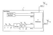
- FIG. 1shows schematically a base station comprising a transmitting device according to the present invention
- FIG. 2shows schematically a mobile terminal comprising a receiving device according to the present invention
- FIGS. 3A and 3Ba first and a second example, respectively, of a pilot symbol pattern transmitted by a first antenna means of a transmitting device according to the present invention
- FIGS. 4A and 4Ba first and a second example, respectively, of a pilot symbol pattern transmitted by the second antenna means of the transmitting device according to the present invention.
- FIG. 1the block diagram of a base station 1 of a wireless orthogonal frequency division multiplex (OFDM) communication system is shown, which comprises a transmitting device according to the present invention. It is to be understood that in FIG. 1 only elements important for the understanding of the present invention are shown. Further elements, such as coding means, modulation means, RF part and the like necessary for the operation of the base station are omitted for the sake of clarity.
- OFDMorthogonal frequency division multiplex
- the base station 1comprises a first antenna 5 and a second antenna 6 being arranged spaced apart from each other, e.g. in a space diversity arrangement.
- the first antenna 5may also be called a non-diversity antenna and the second antenna 6 can also be called a diversity antenna.
- the space diversity arrangement of the first antenna 5 and the second antenna 6is so that the two antennas 5 and 6 are sufficiently separated in space, so that the signals transmitted by the first antenna 5 and the second antenna 6 , respectively, are uncorrelated and an effective diversity gain can be achieved on the receiving side.
- the base station 1comprises a encoding means 3 for encoding a data stream, e.g. on the basis of a space time transmit diversity (STTD) scheme and outputting a first and a second STTD encoded data stream to a multiplexer 4 .
- the first STTD encoded data streamis to be transmitted via the first antenna 5 and the second STTD encoded data stream is to be transmitted via the second antenna 6 .
- the data transmitted from the first antenna 5 and the second antenna 6are generally the same data, i.e. contain the data of the single data stream supplied to the encoding means 3 , the data are not transmitted identically by the two antennas 5 and 6 .
- the data transmitted by the first antenna 5identically correspond to the data arrangement of the single data stream supplied to the encoding means 3 .
- the first data stream output by the encoding meanscan identically correspond to that arrangement (data symbol S 1 followed by data symbol S 2 ).
- the second data stream output by the encoding means 3contains the data symbols S 1 and S 2 in a different arrangement. For example, as shown in FIG.
- the data symbol of the first time period 0 -Tcould be the negative complex conjugated value of the second data block S 2 of the first data stream, i.e. ⁇ S* 2 .
- the next succeeding data symbol of the second data streamis the conjugated complex value of the first data symbol S 1 of the first data stream, i.e. S* 1 .
- the second data streamcontains the identical data content as the first data stream, but in a different arrangement.
- a receiving device receiving the signals from the first antenna 5 and the second antenna 6 as superimposed signalsis therefore able to clearly distinguish between the signals transmitted from the first antenna 5 and the signals transmitted from the second antenna 6 due to the space diversity arrangement and the different arrangement of the same data content.
- the space time transmit diversity scheme shown in and explained in relation to FIG. 1only serves as an example to explain the present invention. Any other STTD scheme for transmitting data via the first antenna 5 and the second antenna 6 can be applied.
- the base station 1further comprises a pilot symbol generating means 2 for generating pilot symbols to be transmitted among the data of the first and the second data stream by the first antenna 5 and the second antenna 6 .
- the pilot symbol generating means 2generates and supplies different pilot symbol patterns to be transmitted via the first antenna 5 and the second antenna 6 , respectively, to the multiplexer 4 .
- the general idea of the present inventionis that some of the pilot symbols transmitted by the first antenna 5 and the second antenna 6 are orthogonal to each other so that the cross-interference from both antennas 5 and 6 is eliminated, the signals from the first, (non-diversity) antenna 5 and the second (diversity) antenna 6 can be differentiated and consequently a separate channel estimation for each antenna 5 , 6 can be achieved in a receiving device.
- FIG. 2shows a schematic block diagram of a mobile terminal 10 comprising a receiving device for receiving signals in a wireless OFDM communication system according to the present invention.
- the mobile terminal 10is adapted to receive signals from a base station 1 as shown in FIG. 1 .
- the mobile terminal 10comprises a single antenna 11 for receiving STTD encoded signals as well as pilot symbols transmitted from the first antenna 5 and the second antenna 6 of the base station 1 . Further, the mobile terminal 10 comprises a receiving means 12 , which comprises e.g. the necessary RF part and the like. Further, the mobile terminal 10 comprises a demodulation means 13 for demodulating signals received by the receiving means 12 via the antenna 11 . It is to be understood that the mobile terminal 10 further comprises all necessary elements to be operated in the corresponding wireless OFDM system. However, these elements are not shown for the sake of clarity.
- the mobile terminal 10further comprises a processing means 14 for detecting pilot symbols in the signals received by the receiving means 12 via the antenna 11 .
- the processing means 14processes detected pilot symbols and performs a channel estimation on the basis of the processing to separately determine the transmission quality of the received signals transmitted from the first antenna 5 and the second antenna 6 , respectively.
- the processing means 14is able to separately determine the transmission quality of the signals transmitted from the first antenna 5 and the transmission quality of the signals transmitted from the second antenna 6 .
- both the STTD encoded signals from the first antenna 5 and from the second antenna 6are further processed and used as communication data in the mobile terminal 10 .
- the second pilot symbols transmitted from the second antenna 6are orthogonal to corresponding first pilot symbols transmitted by the antenna 5 .
- the processing performed in the processing means 14bases on this orthogonality of the first and the second pilot symbols and enables the separate channel estimation for the first and the second antenna 5 and 6 , respectively.
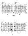
- FIGS. 3 and 4a specific example for pilot symbol patterns to be transmitted by the base station 1 and to be received and processed in the mobile terminal 10 are proposed.
- FIG. 3comprises two FIGS. 3A and 3B .
- FIG. 3Ashows a first example of a pilot symbol pattern to be transmitted by the first (non-diversity) antenna 5 of the base station 1 .
- the shown pilot symbol patternhas a regular distribution in the time and the frequency dimension of the OFDM system.
- the pilot symbols 20 , 21 , . . . , 28are always transmitted in the same frequency subcarriers and in equidistant timepoints.
- the pilot symbols 20 , 21 and 22are transmitted in a first frequency subcarrier, whereby respectively four data symbols are transmitted between adjacent pilot symbols 20 , 21 and 21 , 22 .
- Pilot patterns 23 , 24 and 25are transmitted in a second frequency subcarrier and the pilot symbol 26 , 27 and 28 are transmitted in a third frequency subcarrier.
- the pilot symbols 20 , 23 and 26are transmitted at the same first timepoint
- the pilot symbols 21 , 24 and 27are transmitted in the same second timepoint
- the pilot symbols 22 , 25 and 28are transmitted in the same third timepoint.
- the same frequency subcarriersare used for the transmission of the pilot symbols and the transmission of the pilot symbols in the respective subcarriers always takes place at equidistant timepoints.
- Such a pilot symbol patternis known from prior art OFDM systems.
- the channel estimation for the data symbols between adjacent pilot symbolsis performed by e.g.
- linear interpolationFor example, for the data symbols between the pilot symbols 20 and 21 in the same frequency subcarrier, a linear interpolation of the pilot symbols 20 and 21 is performed on the receiving side. For the data symbols between the adjacent pilot symbols 20 and 23 received at the same timepoint but in different frequency subcarriers, a linear interpolation is also performed. For data symbols in frequency subcarriers, in which no pilot symbols are transmitted, a combination of a time and a frequency interpolation of the respective adjacent pilot symbols is performed.
- FIG. 3Bshows also a regular distribution of the first pilot symbols to be transmitted by the first antenna 5 of the base station 1 .
- the difference to the pilot symbol pattern of FIG. 3Ais here that the (in time) succeeding pilot symbols are not transmitted in the same frequency subcarrier as the preceding pilot symbol, but in the immediately adjacent subcarrier.
- the pilot symbol 31is not transmitted in the same frequency subcarrier as the preceding pilot symbol 30 , but the immediately adjacent (lower) frequency subcarrier.
- This pilot symbol patternmay allow a more accurate channel estimation for data symbols of frequency subcarriers, in which no pilot symbols are transmitted.
- the pilot symbols of the pilot symbol pattern proposed in FIG. 3Bare also transmitted at identical timepoints.
- pilot symbols 30 , 34 and 38are transmitted at the first identical timepoint
- pilot symbols 31 , 35 and 39are transmitted at the same second timepoint
- pilot symbols 32 , 26 and 40are transmitted at the same third timepoint
- pilot symbols 33 , 37 and 41are transmitted at the same fourth timepoint.
- FIG. 4comprises two FIGS. 4A and 4B , whereby FIG. 4A shows the pilot symbol pattern for the second pilot symbols to be transmitted by the second antenna 6 of the base station 1 , which corresponds to the pilot symbol pattern of the first pilot symbols shown in FIG. 3A .
- the pilot symbol pattern of FIG. 4Ashows a very regular distribution of pilot symbols 42 , 43 , . . . , 53 in frequency and time.
- the second pilot symbolsare always transmitted in the same frequency subcarrier and at the same timepoint as the corresponding first pilot symbol.
- the second pilot symbol 42is transmitted in the same frequency subcarrier and at the same timepoint as the corresponding first pilot symbol 20 .
- the second pilot symbol 43is transmitted in the same frequency subcarrier and at the same timepoint as the first pilot symbol 21 .
- the second pilot symbol 46corresponds to the first pilot symbol 23
- the second pilot symbol 50corresponds to the first pilot symbol 26 and so on.
- the second pilot symbols of the pilot symbol pattern in FIG. 4Aare alternatingly identical and orthogonal to the corresponding first pilot symbols of the pilot symbol pattern shown in FIG. 3A .
- the second pilot symbols 42 , 44 , 47 , 50 and 52are identical to their corresponding first pilot symbols 20 , 22 , 24 , 26 and 28 .
- every other second pilot symbol(in time and frequency dimension) is the inverse complex value of the corresponding first pilot symbol.
- a second pilot symbol 43is the inverse complex value of the first pilot symbol 21
- the second pilot symbol 46is the inverse complex value of the first pilot symbol 23
- the second pilot symbol 48 and the first pilot symbol 25 and the second pilot symbol 51 and the first pilot symbol 27are orthogonal to the corresponding pairs of the first pilot symbols, e.g. first pilot symbol 20 and 21 or first pilot symbol 20 and 23 .
- orthogonality in the frequency as well as in the time dimensionis ensured.
- pilot symbol pattern shown in FIG. 4Bwhich corresponds to the pilot symbol pattern shown in FIG. 3B .
- the pilot symbols of the pilot symbol pattern shown in FIG. 4Bare alternatingly identical and orthogonal (inverse complex) to the corresponding first pilot symbols shown in FIG. 3B .
- the pilot symbol scheme proposed by the present inventioncan be applied to any linear channel estimation algorithm in wireless OFDM communications.
- a simple two pilot symbol average based channel estimation algorithm for the pilot symbol patterns of FIG. 3A and FIG. 4Ais used as an example in the following further detailed description.
- the antenna 11 and the receiving means 12 of the mobile terminal 10receive the first and the second pilot symbols as superimposed or combined pilot symbols.
- h 1 1is the channel transfer function from the first antenna 5 to the receiving antenna 11 for the first pilot symbol 20 with value “A”
- h 1 2is the channel transfer function from the second antenna 6 to the receiving antenna 11 for the corresponding second pilot symbol 42 with value “A”
- h 2 1is the channel transfer function from the first antenna 5 to the receiving antenna 11 for the first pilot symbol 21 with value “A”
- h 2 2is the channel transfer function from the second antenna 6 to the receiving antenna 11 for the corresponding second pilot symbol 43 with value “ ⁇ A”.
- n 1 and n 2are the noise values.
- the signals from the first and the second transmitting antenna 5 , 6can be differentiated and consequently a separate channel estimation for each antenna 5 , 6 can be achieved. Since the pilot patterns of the first and the second pilot symbols are orthogonal, the cross-interference from the first and the second antenna 5 and 6 , can be eliminated. Thus, a STTD scheme can be used in a high data rate OFDM wireless communication system. It is to be noted, that the idea of the present invention can also be applied to OFDM based broadband radio access networks (BRAN), like HIPERLAN Type 2 systems.
- BRANbroadband radio access networks
- the pilot symbolsare transmitted in preamble parts of a respective data burst comprising a preamble part and a data part.
- the pilot symbols comprised in the respective preamblesshould be alternatively identical and orthogonal for the two transmitting antennas.
Landscapes
- Engineering & Computer Science (AREA)
- Signal Processing (AREA)
- Computer Networks & Wireless Communication (AREA)
- Power Engineering (AREA)
- Radio Transmission System (AREA)
- Mobile Radio Communication Systems (AREA)
Abstract
Description
y1=A×h11+A×h12+n1
and
y2=A×h21−A×h22+n2,
Claims (30)
Priority Applications (6)
| Application Number | Priority Date | Filing Date | Title |
|---|---|---|---|
| US12/769,958US8532133B2 (en) | 2000-07-05 | 2010-04-29 | Pilot pattern design for a STTD scheme in an OFDM system |
| US13/850,017US8953632B2 (en) | 2000-07-05 | 2013-03-25 | Pilot pattern design for a STTD scheme in an OFDM system |
| US14/591,433US9369323B2 (en) | 2000-07-05 | 2015-01-07 | Pilot pattern design for a STTD scheme in an OFDM system |
| US15/171,176US9596113B2 (en) | 2000-07-05 | 2016-06-02 | Pilot pattern design for a STTD scheme in an OFDM system |
| US15/420,150US9843467B2 (en) | 2000-07-05 | 2017-01-31 | Pilot pattern design for a STTD scheme in an OFDM system |
| US15/819,161US10291454B2 (en) | 2000-07-05 | 2017-11-21 | Pilot pattern design for a STTD scheme in an OFDM system |
Applications Claiming Priority (7)
| Application Number | Priority Date | Filing Date | Title |
|---|---|---|---|
| EP00114423.7 | 2000-07-05 | ||
| EP00114423.7AEP1170897B1 (en) | 2000-07-05 | 2000-07-05 | Pilot pattern design for a STTD scheme in an OFDM system |
| EP00114423 | 2000-07-05 | ||
| US09/898,389US7221645B2 (en) | 2000-07-05 | 2001-07-03 | Pilot pattern design for a STTD scheme in an OFDM system |
| US11/338,644US7646700B2 (en) | 2000-07-05 | 2006-01-25 | Pilot pattern design for an OFDM system |
| US12/250,306US7746759B2 (en) | 2000-07-05 | 2008-10-13 | Pilot pattern design for an OFDM system |
| US12/769,958US8532133B2 (en) | 2000-07-05 | 2010-04-29 | Pilot pattern design for a STTD scheme in an OFDM system |
Related Parent Applications (1)
| Application Number | Title | Priority Date | Filing Date |
|---|---|---|---|
| US12/250,306ContinuationUS7746759B2 (en) | 2000-07-05 | 2008-10-13 | Pilot pattern design for an OFDM system |
Related Child Applications (1)
| Application Number | Title | Priority Date | Filing Date |
|---|---|---|---|
| US13/850,017ContinuationUS8953632B2 (en) | 2000-07-05 | 2013-03-25 | Pilot pattern design for a STTD scheme in an OFDM system |
Publications (2)
| Publication Number | Publication Date |
|---|---|
| US20100226453A1 US20100226453A1 (en) | 2010-09-09 |
| US8532133B2true US8532133B2 (en) | 2013-09-10 |
Family
ID=8169170
Family Applications (15)
| Application Number | Title | Priority Date | Filing Date |
|---|---|---|---|
| US09/898,389Expired - LifetimeUS7221645B2 (en) | 2000-07-05 | 2001-07-03 | Pilot pattern design for a STTD scheme in an OFDM system |
| US11/338,645Expired - LifetimeUS7660228B2 (en) | 2000-07-05 | 2006-01-25 | Pilot pattern design for an OFDM system |
| US11/338,644Expired - LifetimeUS7646700B2 (en) | 2000-07-05 | 2006-01-25 | Pilot pattern design for an OFDM system |
| US11/608,685Expired - LifetimeUS7664009B2 (en) | 2000-07-05 | 2006-12-08 | Pilot pattern design for a STTD scheme in an OFDM system |
| US12/250,306Expired - Fee RelatedUS7746759B2 (en) | 2000-07-05 | 2008-10-13 | Pilot pattern design for an OFDM system |
| US12/250,295Expired - Fee RelatedUS7885175B2 (en) | 2000-07-05 | 2008-10-13 | Pilot pattern design for an OFDM system |
| US12/251,177Expired - Fee RelatedUS7948863B2 (en) | 2000-07-05 | 2008-10-14 | Pilot pattern design for a STTD scheme in an OFDM system |
| US12/769,958Expired - Fee RelatedUS8532133B2 (en) | 2000-07-05 | 2010-04-29 | Pilot pattern design for a STTD scheme in an OFDM system |
| US13/084,293Expired - Fee RelatedUS8483039B2 (en) | 2000-07-05 | 2011-04-11 | Pilot pattern design for a STTD scheme in an OFDM system |
| US13/084,302Expired - LifetimeUS8582417B2 (en) | 2000-07-05 | 2011-04-11 | Pilot pattern design for a STTD scheme in an OFDM system |
| US13/850,017Expired - Fee RelatedUS8953632B2 (en) | 2000-07-05 | 2013-03-25 | Pilot pattern design for a STTD scheme in an OFDM system |
| US14/591,433Expired - Fee RelatedUS9369323B2 (en) | 2000-07-05 | 2015-01-07 | Pilot pattern design for a STTD scheme in an OFDM system |
| US15/171,176Expired - Fee RelatedUS9596113B2 (en) | 2000-07-05 | 2016-06-02 | Pilot pattern design for a STTD scheme in an OFDM system |
| US15/420,150Expired - LifetimeUS9843467B2 (en) | 2000-07-05 | 2017-01-31 | Pilot pattern design for a STTD scheme in an OFDM system |
| US15/819,161Expired - Fee RelatedUS10291454B2 (en) | 2000-07-05 | 2017-11-21 | Pilot pattern design for a STTD scheme in an OFDM system |
Family Applications Before (7)
| Application Number | Title | Priority Date | Filing Date |
|---|---|---|---|
| US09/898,389Expired - LifetimeUS7221645B2 (en) | 2000-07-05 | 2001-07-03 | Pilot pattern design for a STTD scheme in an OFDM system |
| US11/338,645Expired - LifetimeUS7660228B2 (en) | 2000-07-05 | 2006-01-25 | Pilot pattern design for an OFDM system |
| US11/338,644Expired - LifetimeUS7646700B2 (en) | 2000-07-05 | 2006-01-25 | Pilot pattern design for an OFDM system |
| US11/608,685Expired - LifetimeUS7664009B2 (en) | 2000-07-05 | 2006-12-08 | Pilot pattern design for a STTD scheme in an OFDM system |
| US12/250,306Expired - Fee RelatedUS7746759B2 (en) | 2000-07-05 | 2008-10-13 | Pilot pattern design for an OFDM system |
| US12/250,295Expired - Fee RelatedUS7885175B2 (en) | 2000-07-05 | 2008-10-13 | Pilot pattern design for an OFDM system |
| US12/251,177Expired - Fee RelatedUS7948863B2 (en) | 2000-07-05 | 2008-10-14 | Pilot pattern design for a STTD scheme in an OFDM system |
Family Applications After (7)
| Application Number | Title | Priority Date | Filing Date |
|---|---|---|---|
| US13/084,293Expired - Fee RelatedUS8483039B2 (en) | 2000-07-05 | 2011-04-11 | Pilot pattern design for a STTD scheme in an OFDM system |
| US13/084,302Expired - LifetimeUS8582417B2 (en) | 2000-07-05 | 2011-04-11 | Pilot pattern design for a STTD scheme in an OFDM system |
| US13/850,017Expired - Fee RelatedUS8953632B2 (en) | 2000-07-05 | 2013-03-25 | Pilot pattern design for a STTD scheme in an OFDM system |
| US14/591,433Expired - Fee RelatedUS9369323B2 (en) | 2000-07-05 | 2015-01-07 | Pilot pattern design for a STTD scheme in an OFDM system |
| US15/171,176Expired - Fee RelatedUS9596113B2 (en) | 2000-07-05 | 2016-06-02 | Pilot pattern design for a STTD scheme in an OFDM system |
| US15/420,150Expired - LifetimeUS9843467B2 (en) | 2000-07-05 | 2017-01-31 | Pilot pattern design for a STTD scheme in an OFDM system |
| US15/819,161Expired - Fee RelatedUS10291454B2 (en) | 2000-07-05 | 2017-11-21 | Pilot pattern design for a STTD scheme in an OFDM system |
Country Status (4)
| Country | Link |
|---|---|
| US (15) | US7221645B2 (en) |
| EP (4) | EP1720277B1 (en) |
| JP (2) | JP5123451B2 (en) |
| CN (1) | CN1201518C (en) |
Cited By (1)
| Publication number | Priority date | Publication date | Assignee | Title |
|---|---|---|---|---|
| US20170141941A1 (en)* | 2000-07-05 | 2017-05-18 | Sony Deutschland Gmbh | Pilot pattern design for a sttd scheme in an ofdm system |
Families Citing this family (148)
| Publication number | Priority date | Publication date | Assignee | Title |
|---|---|---|---|---|
| US7529289B2 (en)* | 1999-08-31 | 2009-05-05 | Broadcom Corporation | Signal processing under attenuated transmission conditions |
| US8363744B2 (en) | 2001-06-10 | 2013-01-29 | Aloft Media, Llc | Method and system for robust, secure, and high-efficiency voice and packet transmission over ad-hoc, mesh, and MIMO communication networks |
| US6754253B2 (en)* | 2000-11-29 | 2004-06-22 | Ericsson Inc. | Receiver architecture for transmit diversity in CDMA system |
| US7269224B2 (en)* | 2001-09-17 | 2007-09-11 | Bae Systems Information And Electronic Systems Integration Inc. | Apparatus and methods for providing efficient space-time structures for preambles, pilots and data for multi-input, multi-output communications systems |
| US7061854B2 (en)* | 2001-10-15 | 2006-06-13 | Nortel Networks Limited | Efficient OFDM communications with interference immunity |
| US7248559B2 (en)* | 2001-10-17 | 2007-07-24 | Nortel Networks Limited | Scattered pilot pattern and channel estimation method for MIMO-OFDM systems |
| JP3997890B2 (en)* | 2001-11-13 | 2007-10-24 | 松下電器産業株式会社 | Transmission method and transmission apparatus |
| US20030108087A1 (en)* | 2001-12-06 | 2003-06-12 | Itzhak Shperling | Method and base station for providing transmit diversity |
| JP3565344B2 (en)* | 2002-02-21 | 2004-09-15 | 株式会社エヌ・ティ・ティ・ドコモ | Interference removal system and interference removal method |
| US7970962B2 (en)* | 2002-03-15 | 2011-06-28 | Broadcom Corporation | Method and apparatus utilizing a tail bus to solve back-to-back data burst problems |
| US7020226B1 (en)* | 2002-04-04 | 2006-03-28 | Nortel Networks Limited | I/Q distortion compensation for the reception of OFDM signals |
| CA2428576C (en)* | 2002-05-16 | 2008-10-07 | Ntt Docomo, Inc. | Transmitter for multi-carrier transmission and multi-carrier transmitting method |
| CN1170374C (en)* | 2002-06-20 | 2004-10-06 | 大唐移动通信设备有限公司 | Space-time compilation code method suitable for frequency selective fading channels |
| US8194770B2 (en)* | 2002-08-27 | 2012-06-05 | Qualcomm Incorporated | Coded MIMO systems with selective channel inversion applied per eigenmode |
| CN1316759C (en)* | 2002-09-20 | 2007-05-16 | 华为技术有限公司 | Diversity shared transmission method between users of wireless communication system |
| US7889819B2 (en)* | 2002-10-04 | 2011-02-15 | Apurva Mody | Methods and systems for sampling frequency offset detection, correction and control for MIMO OFDM systems |
| US8169944B2 (en)* | 2002-10-25 | 2012-05-01 | Qualcomm Incorporated | Random access for wireless multiple-access communication systems |
| US8570988B2 (en)* | 2002-10-25 | 2013-10-29 | Qualcomm Incorporated | Channel calibration for a time division duplexed communication system |
| US8218609B2 (en)* | 2002-10-25 | 2012-07-10 | Qualcomm Incorporated | Closed-loop rate control for a multi-channel communication system |
| US7002900B2 (en)* | 2002-10-25 | 2006-02-21 | Qualcomm Incorporated | Transmit diversity processing for a multi-antenna communication system |
| US8134976B2 (en) | 2002-10-25 | 2012-03-13 | Qualcomm Incorporated | Channel calibration for a time division duplexed communication system |
| US8208364B2 (en)* | 2002-10-25 | 2012-06-26 | Qualcomm Incorporated | MIMO system with multiple spatial multiplexing modes |
| US8170513B2 (en)* | 2002-10-25 | 2012-05-01 | Qualcomm Incorporated | Data detection and demodulation for wireless communication systems |
| US20040081131A1 (en)* | 2002-10-25 | 2004-04-29 | Walton Jay Rod | OFDM communication system with multiple OFDM symbol sizes |
| US8320301B2 (en)* | 2002-10-25 | 2012-11-27 | Qualcomm Incorporated | MIMO WLAN system |
| US7986742B2 (en) | 2002-10-25 | 2011-07-26 | Qualcomm Incorporated | Pilots for MIMO communication system |
| US7324429B2 (en) | 2002-10-25 | 2008-01-29 | Qualcomm, Incorporated | Multi-mode terminal in a wireless MIMO system |
| US7508798B2 (en)* | 2002-12-16 | 2009-03-24 | Nortel Networks Limited | Virtual mimo communication system |
| JP2006511154A (en)* | 2002-12-19 | 2006-03-30 | コーニンクレッカ フィリップス エレクトロニクス エヌ ヴィ | Transmitter diversity method for OFDM system |
| JP3669991B2 (en) | 2003-02-18 | 2005-07-13 | 三星電子株式会社 | Wireless transceiver, wireless transmission / reception method and program thereof |
| CN101951677B (en)* | 2003-02-24 | 2013-03-27 | 高通股份有限公司 | Channel quality report method used by wireless terminal, wireless terminal and base station |
| CN1778058B (en)* | 2003-02-24 | 2010-11-10 | 高通股份有限公司 | Channel quality reporting method used by wireless terminal, wireless terminal and base station |
| JP4133531B2 (en)* | 2003-04-15 | 2008-08-13 | シャープ株式会社 | Wireless communication apparatus and wireless communication system |
| FR2854020B1 (en)* | 2003-04-17 | 2005-09-09 | Wavecom | METHOD OF TRANSMITTING RADIO DATA USING MULTIPLE SEPARATE DRIVER PATTERNS, CORRESPONDING RECEPTION METHOD, SYSTEM, MOBILE AND CORRESPONDING STATION |
| KR100922980B1 (en) | 2003-05-02 | 2009-10-22 | 삼성전자주식회사 | Channel Estimation Apparatus and Method in Orthogonal Frequency Division Multiplexing System Using Multiple Antennas |
| EP1489807B1 (en)* | 2003-06-11 | 2007-11-14 | NTT DoCoMo, Inc. | OFDM signal frame generator with adaptive pilot and data arrangement |
| US7773694B2 (en)* | 2003-07-02 | 2010-08-10 | Panasonic Corporation | Communication apparatus and communication method |
| US7305055B1 (en)* | 2003-08-18 | 2007-12-04 | Qualcomm Incorporated | Search-efficient MIMO trellis decoder |
| KR100950646B1 (en)* | 2003-10-16 | 2010-04-01 | 삼성전자주식회사 | Preamble Transmission Method for Synchronization of Multiplexed Orthogonal Frequency Division Multiplexing Systems |
| US7532563B1 (en)* | 2003-11-25 | 2009-05-12 | Marvell International Ltd. | Mechanism to improve quality of channel estimates in OFDM transmissions |
| US9473269B2 (en) | 2003-12-01 | 2016-10-18 | Qualcomm Incorporated | Method and apparatus for providing an efficient control channel structure in a wireless communication system |
| EP1542488A1 (en) | 2003-12-12 | 2005-06-15 | Telefonaktiebolaget LM Ericsson (publ) | Method and apparatus for allocating a pilot signal adapted to the channel characteristics |
| US7450489B2 (en)* | 2003-12-30 | 2008-11-11 | Intel Corporation | Multiple-antenna communication systems and methods for communicating in wireless local area networks that include single-antenna communication devices |
| GB2410396A (en)* | 2004-01-20 | 2005-07-27 | Ubinetics Ltd | Pilot signal manipulation in transmit diversity communications |
| US7339999B2 (en)* | 2004-01-21 | 2008-03-04 | Qualcomm Incorporated | Pilot transmission and channel estimation for an OFDM system with excess delay spread |
| US8194771B2 (en)* | 2004-01-27 | 2012-06-05 | Agere Systems Inc. | Transmission method and apparatus in a multiple antenna communication system |
| ES2885101T3 (en) | 2004-01-29 | 2021-12-13 | Neo Wireless Llc | Procedures and apparatus for superimposing direct sequence and multi-carrier spread spectrum signals in a broadband wireless communication system |
| US7742533B2 (en) | 2004-03-12 | 2010-06-22 | Kabushiki Kaisha Toshiba | OFDM signal transmission method and apparatus |
| CN1832466B (en)* | 2004-03-12 | 2011-05-04 | 株式会社东芝 | Ofdm signal transmission method and apparatus |
| EP1726111B1 (en)* | 2004-03-15 | 2019-05-29 | Apple Inc. | Pilot design for ofdm systems with four transmit antennas |
| US8958493B2 (en) | 2004-03-31 | 2015-02-17 | Infineon Technologies Ag | Operation for backward-compatible transmission |
| CN1677969B (en)* | 2004-03-31 | 2010-10-13 | 因芬尼昂技术股份公司 | Improved operation of backward-compatible transmission |
| EP1583277A1 (en)* | 2004-03-31 | 2005-10-05 | Infineon Technologies AG | MIMO-OFDM backward-compatible transmission system |
| US7684507B2 (en)* | 2004-04-13 | 2010-03-23 | Intel Corporation | Method and apparatus to select coding mode |
| JP2005341531A (en)* | 2004-04-27 | 2005-12-08 | Matsushita Electric Ind Co Ltd | Radio communication system and radio station |
| US7693124B2 (en) | 2004-05-18 | 2010-04-06 | Qualcomm Incorporated | Slot-to-interlace and interlace-to-slot converters for an OFDM system |
| EP1766806B1 (en) | 2004-06-22 | 2017-11-01 | Apple Inc. | Closed loop mimo systems and methods |
| EP2993851B1 (en) | 2004-06-24 | 2019-04-24 | Apple Inc. | Preambles in ofdma system |
| US8014377B2 (en) | 2004-06-24 | 2011-09-06 | Nortel Networks Limited | Efficient location updates, paging and short bursts |
| US8027243B2 (en)* | 2004-06-25 | 2011-09-27 | Lg Electronics Inc. | Allocation of radio resource in orthogonal frequency division multiplexing system |
| RU2364033C2 (en)* | 2004-07-07 | 2009-08-10 | Самсунг Электроникс Ко., Лтд. | Device and method of pilot carriertransmission in bwa communication system by transmitter antennas |
| WO2006002550A1 (en)* | 2004-07-07 | 2006-01-12 | Nortel Networks Limited | System and method for mapping symbols for mimo transmission |
| US20060009168A1 (en)* | 2004-07-12 | 2006-01-12 | Lucent Technologies, Inc. | Method for controlling transmissions using both diversity and nondiversity transmission schemes |
| JP2006033083A (en)* | 2004-07-12 | 2006-02-02 | Oki Electric Ind Co Ltd | OFDM transmission system. |
| WO2006014143A1 (en)* | 2004-08-03 | 2006-02-09 | Agency For Science, Technology And Research | Method for transmitting a digital data stream, transmitter, method for receiving a digital data stream and receiver |
| US20060045192A1 (en)* | 2004-08-25 | 2006-03-02 | Hiroshi Hayashi | Method and apparatus for pilot channel transmission and reception within a multi-carrier communication system |
| US8040968B2 (en)* | 2004-09-30 | 2011-10-18 | Intel Corporation | High rate, high diversity transmission on multiple transmit antennas |
| WO2006039812A1 (en) | 2004-10-15 | 2006-04-20 | Nortel Networks Limited | Communication resource allocation systems and methods |
| US8571132B2 (en)* | 2004-12-22 | 2013-10-29 | Qualcomm Incorporated | Constrained hopping in wireless communication systems |
| KR101087111B1 (en)* | 2004-12-27 | 2011-11-25 | 엘지전자 주식회사 | Data transmission and reception method in wireless communication system |
| US7542515B2 (en)* | 2004-12-29 | 2009-06-02 | Intel Corporation | Training symbol format for adaptively power loaded MIMO |
| US8045599B2 (en) | 2005-02-17 | 2011-10-25 | Sony Corporation | Selection of training sequences for multiple-in multiple-out transmissions |
| JP4616030B2 (en)* | 2005-02-17 | 2011-01-19 | 三星電子株式会社 | Wireless transmission device, wireless reception device, transmission / reception method, and computer program |
| CN1832464B (en)* | 2005-03-11 | 2010-09-15 | 中兴通讯股份有限公司 | Pilot distribution device of orthogonal frequency division duplex system and its method |
| GB2425922B (en)* | 2005-05-03 | 2007-08-01 | Motorola Inc | Transmission of signalling information in an OFDM communication system |
| US7466749B2 (en) | 2005-05-12 | 2008-12-16 | Qualcomm Incorporated | Rate selection with margin sharing |
| US8126066B2 (en)* | 2005-06-09 | 2012-02-28 | Telefonaktiebolaget Lm Ericsson (Publ) | Time and frequency channel estimation |
| US8358714B2 (en)* | 2005-06-16 | 2013-01-22 | Qualcomm Incorporated | Coding and modulation for multiple data streams in a communication system |
| US7660229B2 (en)* | 2005-06-20 | 2010-02-09 | Texas Instruments Incorporated | Pilot design and channel estimation |
| KR100767312B1 (en)* | 2005-09-05 | 2007-10-17 | 한국전자통신연구원 | Apparatus for generating down link signal, and method and apparatus for cell search in cellular system |
| EP2840724B1 (en)* | 2005-09-30 | 2019-11-20 | Apple Inc. | MIMO communication system |
| US7813448B2 (en)* | 2005-10-31 | 2010-10-12 | Broadcom Corporation | Cyclic delay diversity in a wireless system |
| US7917176B2 (en)* | 2006-02-14 | 2011-03-29 | Nec Laboratories America, Inc. | Structured codebook and successive beamforming for multiple-antenna systems |
| CN100358258C (en)* | 2005-11-11 | 2007-12-26 | 南京邮电大学 | Combined delay space emission diversity scheme in CDMA system |
| ATE412297T1 (en)* | 2005-12-02 | 2008-11-15 | Alcatel Lucent | MULTI CARRIER SIGNAL WITH SELECTABLE PILOT PATTERN |
| EP1793549B1 (en) | 2005-12-02 | 2008-10-15 | Alcatel Lucent | Digital receiver for FDM signals |
| EP1804452B1 (en)* | 2006-01-03 | 2011-05-11 | Alcatel Lucent | Scheduling of control channels in multicarrier transmission systems |
| EP1806892A1 (en)* | 2006-01-10 | 2007-07-11 | Alcatel Lucent | Method of separating signals in a cellular multicarrier telecommunication system |
| JP4751733B2 (en)* | 2006-02-13 | 2011-08-17 | 富士通東芝モバイルコミュニケーションズ株式会社 | OFDM wireless communication system |
| EP1830534A1 (en)* | 2006-03-03 | 2007-09-05 | Alcatel Lucent | Active cancellation of inter-cell interference in a cellular wireless access system |
| US7706459B2 (en)* | 2006-03-10 | 2010-04-27 | Beceem Communications Inc. | System and method for channel estimation |
| WO2007109064A1 (en)* | 2006-03-17 | 2007-09-27 | Interdigital Technology Corporation | Method and apparatus for channel estimation using time-frequency localized pilots and de-noising techniques |
| EP1988729A4 (en)* | 2006-03-17 | 2012-04-11 | Panasonic Corp | WIRELESS COMMUNICATION BASE STATION DEVICE AND PILOT SIGNAL POSITIONING METHOD |
| US20080026441A1 (en)* | 2006-07-26 | 2008-01-31 | Diane Fournier | Production of probiotic bacteria using maple sap |
| US7889799B2 (en)* | 2006-08-02 | 2011-02-15 | Telefonaktiebolaget Lm Ericsson (Publ) | Method and apparatus for OFDM channel estimation |
| WO2008023349A2 (en)* | 2006-08-23 | 2008-02-28 | Nokia Corporation | Pilot design for long term evolution uplink multi-input multi-output antenna system |
| CN101512998B (en)* | 2006-09-11 | 2013-05-01 | 艾利森电话股份有限公司 | Method and device for detecting pilot pattern |
| US8503402B2 (en)* | 2006-09-14 | 2013-08-06 | Telefonaktiebolaget L M Ericsson (Publ) | Method and arrangements for load balancing of power amplifiers |
| JP4855888B2 (en)* | 2006-10-03 | 2012-01-18 | 株式会社エヌ・ティ・ティ・ドコモ | Base station equipment |
| KR100962114B1 (en)* | 2006-11-23 | 2010-06-10 | 삼성전자주식회사 | Apparatus and Method for Channel Estimation in Broadband Wireless Communication Systems |
| US8300674B2 (en)* | 2007-01-12 | 2012-10-30 | Telefonaktiebolaget L M Ericsson (Publ) | Method and apparatus for complexity reduction in detection of delay and Doppler shifted signature sequences |
| US7720164B2 (en)* | 2007-02-26 | 2010-05-18 | Telefonaktiebolaget L M Ericsson (Publ) | Transmission scheme for uplink access in a FDMA system |
| GB2449470B (en)* | 2007-05-23 | 2011-06-29 | British Broadcasting Corp | OFDM-MIMO radio frequency transmission system |
| AU2013203046B2 (en)* | 2007-05-23 | 2015-11-05 | British Broadcasting Corporation | Ofdm-mimo radio frequency transmission system |
| US8279743B2 (en) | 2007-05-31 | 2012-10-02 | Telefonaktiebolaget Lm Ericsson (Publ) | Method for interference estimation for orthogonal pilot patterns |
| JP2009033666A (en)* | 2007-07-30 | 2009-02-12 | Toshiba Corp | Wireless communication apparatus, wireless transmission method, and wireless reception method |
| US20090060063A1 (en)* | 2007-08-31 | 2009-03-05 | Telefonaktiebolaget Lm Ericsson (Publ) | Method and Apparatus for Robust Control Signaling Distribution in OFDM Systems |
| KR101520667B1 (en)* | 2007-09-10 | 2015-05-18 | 엘지전자 주식회사 | Allocation method of pilot subcarriers in mimo system |
| US7652980B2 (en)* | 2007-11-02 | 2010-01-26 | Nokia Corporation | Orthogonal frequency division multiplexing synchronization |
| CN101953108A (en)* | 2007-11-02 | 2011-01-19 | 诺基亚西门子通信公司 | Method and apparatus for providing an efficient pilot pattern |
| EP2061161B1 (en)* | 2007-11-14 | 2013-03-20 | Sony Corporation | Improved Alamouti encoding and decoding |
| EP2073419B1 (en) | 2007-12-20 | 2011-10-26 | Panasonic Corporation | Control channel signaling using a common signaling field for transport format and redundancy version |
| WO2009086670A1 (en)* | 2007-12-29 | 2009-07-16 | Alcatel Shanghai Bell Co., Ltd. | Method and equipment for mapping a pilot |
| KR101498060B1 (en)* | 2008-02-19 | 2015-03-03 | 엘지전자 주식회사 | Method for uplink transmittion in an ofdm(a) system |
| KR101527022B1 (en)* | 2008-03-14 | 2015-06-09 | 엘지전자 주식회사 | A pilot transmission method in a wireless communication system having multiple antennas |
| CN101272372B (en)* | 2008-03-31 | 2010-10-06 | 北京北方烽火科技有限公司 | OFDM automatic closed-loop transmitting scattered pilot insertion control method |
| US8724718B2 (en)* | 2008-04-10 | 2014-05-13 | Mediatek Inc. | Pilot pattern design for small size resource block in OFDMA systems |
| US20090257342A1 (en)* | 2008-04-10 | 2009-10-15 | Media Tek Inc. | Resource block based pilot pattern design for 1/2 - stream mimo ofdma systems |
| US8811331B2 (en)* | 2008-04-10 | 2014-08-19 | Telefonaktiebolaget L M Ericsson (Publ) | Pilot design using costas arrays |
| JP5169423B2 (en)* | 2008-04-16 | 2013-03-27 | 富士通株式会社 | Mobile station apparatus and transmission path estimation method |
| ES2431337T3 (en)* | 2008-06-04 | 2013-11-26 | Sony Corporation | New frame structure for multiple carrier systems |
| US8811339B2 (en) | 2008-07-07 | 2014-08-19 | Blackberry Limited | Handover schemes for wireless systems |
| US8665803B2 (en) | 2008-07-31 | 2014-03-04 | Qualcomm Incorporated | Tone selection in communication networks |
| GB2464289B (en)* | 2008-10-08 | 2012-12-05 | Samsung Electronics Co Ltd | Estimating link qualities in multi-carrier systems |
| CN101741420B (en) | 2008-11-12 | 2013-08-07 | 华为技术有限公司 | Channel estimation methods, device and system |
| US8737502B2 (en)* | 2009-02-09 | 2014-05-27 | Qualcomm Incorporated | Multiplexing and coding schemes for multiple transmit antennas in a wireless communication system |
| GB0916001D0 (en)* | 2009-09-11 | 2009-10-28 | Univ Edinburgh | Inter-carrier modulation |
| US8503553B2 (en)* | 2009-12-17 | 2013-08-06 | Texas Instruments Incorporated | Pilot subcarriers in wireless transmissions |
| KR101624879B1 (en)* | 2009-12-23 | 2016-05-30 | 삼성전자주식회사 | Method for Assigning and Managing Reference Signals in Multi-Cell Environment, Network Device and Terminal of Enabling the Method |
| US8576936B2 (en)* | 2010-01-25 | 2013-11-05 | Harris Corporation | Method and apparatus for high speed data transmission modulation and demodulation |
| JP5144709B2 (en) | 2010-04-21 | 2013-02-13 | 株式会社日立国際電気 | Mobile station equipment |
| CN102299731B (en)* | 2010-06-28 | 2016-06-29 | 中兴通讯股份有限公司 | The discharger of ofdm system and the method for raising cyclic delay diversity performance |
| US9930567B1 (en) | 2011-02-03 | 2018-03-27 | Horizon Hobby, LLC | Three dimensional spread spectrum remote control system |
| US20130315323A1 (en)* | 2011-04-24 | 2013-11-28 | Broadcom Corporation | Traveling pilots within single user, multiple user, multiple access, and/or MIMO wireless communications |
| US20120269142A1 (en)* | 2011-04-24 | 2012-10-25 | Broadcom Corporation | Doppler adaptation using pilot patterns within single user, multiple user, multiple access, and/or MIMO wireless communications |
| EP2525533B1 (en)* | 2011-05-16 | 2014-02-26 | Alcatel Lucent | Method and apparatus for providing bidirectional communication between segments of a home network |
| US9143365B2 (en)* | 2013-01-30 | 2015-09-22 | Qualcomm Incorporated | Channel estimation using averaging and interpolation |
| US9401823B2 (en) | 2013-11-26 | 2016-07-26 | Plusn Llc | System and method for radio frequency carrier aggregation |
| CN104539565A (en)* | 2015-02-02 | 2015-04-22 | 中山大学花都产业科技研究院 | MIMO-OFDM channel estimator designed based on quadratic curve fitting method |
| CN107171700B (en)* | 2016-03-08 | 2021-09-07 | 索尼公司 | Electronic device and communication method for communication device with multiple antennas |
| US10476569B1 (en)* | 2016-11-28 | 2019-11-12 | Amazon Technologies, Inc. | Antenna selection for interference avoidance |
| US10904729B2 (en)* | 2016-12-20 | 2021-01-26 | Verizon Patent And Licensing Inc. | System and method for improved capacity using channel multiplexing |
| US10778384B2 (en)* | 2016-12-20 | 2020-09-15 | Verizon Patent And Licensing Inc. | System and method for improved capacity using channel multiplexing |
| FR3087980A1 (en)* | 2018-10-25 | 2020-05-01 | Orange | METHOD FOR TRANSMITTING PILOT SYMBOLS |
| WO2021025949A1 (en) | 2019-08-05 | 2021-02-11 | Shure Acquisition Holdings, Inc. | Transmit antenna diversity wireless audio system |
| US11496189B2 (en)* | 2020-05-29 | 2022-11-08 | Qualcomm Incorporated | Techniques for processing digital post distortion using additional reference symbols |
| US11652667B2 (en)* | 2020-11-25 | 2023-05-16 | Silicon Laboratories Inc. | System and method for detecting of channel conditions and channel estimation in an orthogonal frequency division multiplexing (OFDM) receiver |
| KR102487892B1 (en)* | 2022-10-26 | 2023-01-12 | 주식회사 코메스타 | Ship centric direct communication and method of performing thereof |
Citations (23)
| Publication number | Priority date | Publication date | Assignee | Title |
|---|---|---|---|---|
| EP0810742A2 (en) | 1996-05-30 | 1997-12-03 | Ntt Mobile Communications Network Inc. | Direct sequence code division multiple access transmission method using pilot symbols |
| WO1998038758A2 (en) | 1997-02-28 | 1998-09-03 | Interdigital Technology Corporation | Orthogonal code synchronization system and method for spread spectrum cdma communications |
| EP0876002A2 (en) | 1997-04-30 | 1998-11-04 | Lucent Technologies Inc. | Pilot interference cancellation for a coherent wireless code division multiple access receiver |
| WO1998059450A1 (en) | 1997-06-20 | 1998-12-30 | Motorola Inc. | Synchronous coherent orthogonal frequency division multiplexing system |
| EP0898381A2 (en) | 1997-08-20 | 1999-02-24 | Samsung Electronics Co., Ltd. | Equalizing method and equalizer for ofdm receiver |
| EP0938208A1 (en) | 1998-02-22 | 1999-08-25 | Sony International (Europe) GmbH | Multicarrier transmission, compatible with the existing GSM system |
| US6005876A (en) | 1996-03-08 | 1999-12-21 | At&T Corp | Method and apparatus for mobile data communication |
| EP0993129A2 (en) | 1998-10-07 | 2000-04-12 | Texas Instruments Incorporated | Channel estimation in space time block coded transmit antenna diversity for WCDMA |
| WO2001047167A1 (en) | 1999-12-21 | 2001-06-28 | Nokia Corporation | Estimation of two propagation channels in ofdm |
| US6359926B1 (en)* | 1996-09-02 | 2002-03-19 | Stmicroelectronics N.V. | Multi-carrier transmission systems |
| US20020041635A1 (en)* | 2000-09-01 | 2002-04-11 | Jianglei Ma | Preamble design for multiple input - multiple output (MIMO), orthogonal frequency division multiplexing (OFDM) system |
| US6618454B1 (en) | 1998-02-06 | 2003-09-09 | At&T Corp. | Diversity coded OFDM for high data-rate communication |
| US6643338B1 (en) | 1998-10-07 | 2003-11-04 | Texas Instruments Incorporated | Space time block coded transmit antenna diversity for WCDMA |
| US6654339B1 (en) | 1999-01-08 | 2003-11-25 | Sony International (Europe) Gmbh | Synchronization symbol structure using OFDM based transmission method |
| US6728302B1 (en) | 1999-02-12 | 2004-04-27 | Texas Instruments Incorporated | STTD encoding for PCCPCH |
| US6795392B1 (en) | 2000-03-27 | 2004-09-21 | At&T Corp. | Clustered OFDM with channel estimation |
| US6853689B1 (en) | 1999-07-15 | 2005-02-08 | Telefonaktiebolaget Lm Ericsson | Method and apparatus for channel estimation with transmit diversity |
| US6961364B1 (en) | 2000-04-18 | 2005-11-01 | Flarion Technologies, Inc. | Base station identification in orthogonal frequency division multiplexing based spread spectrum multiple access systems |
| US7006579B2 (en) | 2000-09-29 | 2006-02-28 | Nokia Corporation | ISI-robust slot formats for non-orthogonal-based space-time block codes |
| US7068628B2 (en) | 2000-05-22 | 2006-06-27 | At&T Corp. | MIMO OFDM system |
| US7149253B2 (en) | 2000-03-21 | 2006-12-12 | Texas Instruments Incorporated | Wireless communication |
| US7292651B2 (en) | 1998-12-31 | 2007-11-06 | At&T Corp. | Pilot-aided channel estimation for OFDM in wireless systems |
| US20090041141A1 (en) | 2000-07-05 | 2009-02-12 | Sony International (Europe) Gmbh | Pilot pattern design for an ofdm system |
Family Cites Families (14)
| Publication number | Priority date | Publication date | Assignee | Title |
|---|---|---|---|---|
| US332516A (en)* | 1885-12-15 | Assigkob op | ||
| US332491A (en)* | 1885-12-15 | Device for preventing drafts beneath floors | ||
| US332495A (en)* | 1885-12-15 | Door or shutter fastener | ||
| US5728302A (en)* | 1992-04-09 | 1998-03-17 | Groundwater Services, Inc. | Methods for the removal of contaminants from subterranean fluids |
| EP1146518B1 (en)* | 1993-03-23 | 2002-12-11 | Matsushita Electric Industrial Co., Ltd. | Combination of a cartridge adaptor and a cartridge to be accommodated in the adaptor |
| US6334219B1 (en)* | 1994-09-26 | 2001-12-25 | Adc Telecommunications Inc. | Channel selection for a hybrid fiber coax network |
| US6131016A (en)* | 1997-08-27 | 2000-10-10 | At&T Corp | Method and apparatus for enhancing communication reception at a wireless communication terminal |
| EP0939527B1 (en)* | 1998-02-18 | 2007-12-05 | Sony Deutschland GmbH | Mapping of multicarrier signals into GSM time slots |
| JP3363086B2 (en)* | 1998-03-04 | 2003-01-07 | 株式会社東芝 | OFDM receiver |
| US6795424B1 (en)* | 1998-06-30 | 2004-09-21 | Tellabs Operations, Inc. | Method and apparatus for interference suppression in orthogonal frequency division multiplexed (OFDM) wireless communication systems |
| US6707856B1 (en)* | 1999-10-07 | 2004-03-16 | Cisco Technology | Transmission of system configuration information |
| US6473467B1 (en)* | 2000-03-22 | 2002-10-29 | Qualcomm Incorporated | Method and apparatus for measuring reporting channel state information in a high efficiency, high performance communications system |
| JP2002009733A (en)* | 2000-06-27 | 2002-01-11 | Hitachi Kokusai Electric Inc | Transmission apparatus employing orthogonal frequency division multiplexing modulation system |
| US6792392B1 (en)* | 2000-06-30 | 2004-09-14 | Intel Corporation | Method and apparatus for configuring and collecting performance counter data |
- 2000
- 2000-07-05EPEP06016025.6Apatent/EP1720277B1/ennot_activeExpired - Lifetime
- 2000-07-05EPEP10181124Apatent/EP2262157A3/ennot_activeWithdrawn
- 2000-07-05EPEP10181109.9Apatent/EP2262151B1/ennot_activeExpired - Lifetime
- 2000-07-05EPEP00114423.7Apatent/EP1170897B1/ennot_activeExpired - Lifetime
- 2001
- 2001-07-03USUS09/898,389patent/US7221645B2/ennot_activeExpired - Lifetime
- 2001-07-05CNCNB011217421Apatent/CN1201518C/ennot_activeExpired - Lifetime
- 2001-07-05JPJP2001205330Apatent/JP5123451B2/ennot_activeExpired - Lifetime
- 2006
- 2006-01-25USUS11/338,645patent/US7660228B2/ennot_activeExpired - Lifetime
- 2006-01-25USUS11/338,644patent/US7646700B2/ennot_activeExpired - Lifetime
- 2006-12-08USUS11/608,685patent/US7664009B2/ennot_activeExpired - Lifetime
- 2008
- 2008-07-09JPJP2008179163Apatent/JP5001230B2/ennot_activeExpired - Lifetime
- 2008-10-13USUS12/250,306patent/US7746759B2/ennot_activeExpired - Fee Related
- 2008-10-13USUS12/250,295patent/US7885175B2/ennot_activeExpired - Fee Related
- 2008-10-14USUS12/251,177patent/US7948863B2/ennot_activeExpired - Fee Related
- 2010
- 2010-04-29USUS12/769,958patent/US8532133B2/ennot_activeExpired - Fee Related
- 2011
- 2011-04-11USUS13/084,293patent/US8483039B2/ennot_activeExpired - Fee Related
- 2011-04-11USUS13/084,302patent/US8582417B2/ennot_activeExpired - Lifetime
- 2013
- 2013-03-25USUS13/850,017patent/US8953632B2/ennot_activeExpired - Fee Related
- 2015
- 2015-01-07USUS14/591,433patent/US9369323B2/ennot_activeExpired - Fee Related
- 2016
- 2016-06-02USUS15/171,176patent/US9596113B2/ennot_activeExpired - Fee Related
- 2017
- 2017-01-31USUS15/420,150patent/US9843467B2/ennot_activeExpired - Lifetime
- 2017-11-21USUS15/819,161patent/US10291454B2/ennot_activeExpired - Fee Related
Patent Citations (28)
| Publication number | Priority date | Publication date | Assignee | Title |
|---|---|---|---|---|
| US6005876A (en) | 1996-03-08 | 1999-12-21 | At&T Corp | Method and apparatus for mobile data communication |
| EP0810742A2 (en) | 1996-05-30 | 1997-12-03 | Ntt Mobile Communications Network Inc. | Direct sequence code division multiple access transmission method using pilot symbols |
| US6359926B1 (en)* | 1996-09-02 | 2002-03-19 | Stmicroelectronics N.V. | Multi-carrier transmission systems |
| WO1998038758A2 (en) | 1997-02-28 | 1998-09-03 | Interdigital Technology Corporation | Orthogonal code synchronization system and method for spread spectrum cdma communications |
| EP0876002A2 (en) | 1997-04-30 | 1998-11-04 | Lucent Technologies Inc. | Pilot interference cancellation for a coherent wireless code division multiple access receiver |
| WO1998059450A1 (en) | 1997-06-20 | 1998-12-30 | Motorola Inc. | Synchronous coherent orthogonal frequency division multiplexing system |
| US5867478A (en) | 1997-06-20 | 1999-02-02 | Motorola, Inc. | Synchronous coherent orthogonal frequency division multiplexing system, method, software and device |
| EP0898381A2 (en) | 1997-08-20 | 1999-02-24 | Samsung Electronics Co., Ltd. | Equalizing method and equalizer for ofdm receiver |
| US6618454B1 (en) | 1998-02-06 | 2003-09-09 | At&T Corp. | Diversity coded OFDM for high data-rate communication |
| EP0938208A1 (en) | 1998-02-22 | 1999-08-25 | Sony International (Europe) GmbH | Multicarrier transmission, compatible with the existing GSM system |
| EP0993129A2 (en) | 1998-10-07 | 2000-04-12 | Texas Instruments Incorporated | Channel estimation in space time block coded transmit antenna diversity for WCDMA |
| US6643338B1 (en) | 1998-10-07 | 2003-11-04 | Texas Instruments Incorporated | Space time block coded transmit antenna diversity for WCDMA |
| US7292651B2 (en) | 1998-12-31 | 2007-11-06 | At&T Corp. | Pilot-aided channel estimation for OFDM in wireless systems |
| US6654339B1 (en) | 1999-01-08 | 2003-11-25 | Sony International (Europe) Gmbh | Synchronization symbol structure using OFDM based transmission method |
| US6728302B1 (en) | 1999-02-12 | 2004-04-27 | Texas Instruments Incorporated | STTD encoding for PCCPCH |
| US6853689B1 (en) | 1999-07-15 | 2005-02-08 | Telefonaktiebolaget Lm Ericsson | Method and apparatus for channel estimation with transmit diversity |
| WO2001047167A1 (en) | 1999-12-21 | 2001-06-28 | Nokia Corporation | Estimation of two propagation channels in ofdm |
| US7149253B2 (en) | 2000-03-21 | 2006-12-12 | Texas Instruments Incorporated | Wireless communication |
| US6795392B1 (en) | 2000-03-27 | 2004-09-21 | At&T Corp. | Clustered OFDM with channel estimation |
| US6961364B1 (en) | 2000-04-18 | 2005-11-01 | Flarion Technologies, Inc. | Base station identification in orthogonal frequency division multiplexing based spread spectrum multiple access systems |
| US7068628B2 (en) | 2000-05-22 | 2006-06-27 | At&T Corp. | MIMO OFDM system |
| US20090041141A1 (en) | 2000-07-05 | 2009-02-12 | Sony International (Europe) Gmbh | Pilot pattern design for an ofdm system |
| US20090041142A1 (en)* | 2000-07-05 | 2009-02-12 | Sony Deutschland Gmbh | Pilot pattern design for an ofdm system |
| US20090080561A1 (en) | 2000-07-05 | 2009-03-26 | Sony Deutschland Gmbh | Pilot pattern design for a sttd scheme in an ofdm system |
| US7660228B2 (en) | 2000-07-05 | 2010-02-09 | Sony Deutschland Gmbh | Pilot pattern design for an OFDM system |
| US7664009B2 (en) | 2000-07-05 | 2010-02-16 | Sony Deutschland Gmbh | Pilot pattern design for a STTD scheme in an OFDM system |
| US20020041635A1 (en)* | 2000-09-01 | 2002-04-11 | Jianglei Ma | Preamble design for multiple input - multiple output (MIMO), orthogonal frequency division multiplexing (OFDM) system |
| US7006579B2 (en) | 2000-09-29 | 2006-02-28 | Nokia Corporation | ISI-robust slot formats for non-orthogonal-based space-time block codes |
Non-Patent Citations (15)
| Title |
|---|
| "ETSI EN 300 744" V1.5.1 (Jun. 2004), European Standard (Telecommunications series), Digital Video Broadcasting (DVB); Framing structure, channel coding and modulation for digital terrestrial television, European Broadcasting Union, pp. 1-64. |
| "TS 25.211" V3.0.0 (Oct. 1999) Technical Specification, 3rd Generation Partnership Project (3GPP); Technical Specification Group (TSG) Radi Access Network (RAN); Working Group 1 (WG1); Physical channels and mapping of transport channels onto physical channels (FDD), TSG RAN Meeting No. 5, October, Kyongju, Korea, pp. 1-38. |
| Ayman F. Naguib et al.; "Space-Time Coding and Signal Processing for High Data Rate Wireless Communications", IEEE Signal Processing Magazine, vol. 17, No. 3, May 2000, pp. 76-92. |
| Ayman F. Naguib, et al., "A Space-Time Coding Modem for High-Data-Rate Wireless Communications", IEEE Journal On Selected Areas In Communications, vol. 16, No. 8, Oct. 1998, pp. 1459-1478. |
| Dakshi Agrawal, et al., "Space-Time Coded OFDM for High Date-Rate Wireless Communication Over Wideband Channels", IEEE, VTC '98, 1998, pp. 2232-2236. |
| Frederick W. Vook, et al., "Technical Diversity Schemes for Broadband Mobile Communication Systems", IEEE, VTC 2000, pp. 2523-2529. |
| Fredrik Tufvesson et al.; "Pilot Assisted Channel Estimation for OFDM in Mobile Cellular Systems", Vehicular Technology Conference, vol. 3, May 4, 1997, pp. 1639-1643. |
| Office Communication pursuant to Article 94(3) EPC issued Jan. 19, 2012, in European Patent Application No. 06 016 025.6. |
| Siavash M. Alamouti; "A Simple Transmit Diversity Technique for Wireless Communication", IEEE Journal on Select Areas in Communication, vol. 16, No. 8, Oct. 1998, pp. 1451-1485. |
| Tai-Ann Chen et al., "Two Dimensional Space-Time Pilot Symbol Assisted Demodulation over Frequency Nonselective Rayleigh Fading Channels", Wireless Communications and Networking Conference, Sep. 21, 1999, pp. 1065-1069. |
| U.S. Appl. No. 13/084,293, filed Apr. 11, 2011, Wang, et al. |
| U.S. Appl. No. 13/084,302, filed Apr. 11, 2011, Wang, et al. |
| Vahid Tarokh, et al., "Space-Time Codes for High Data Rate Wireless Communication: Performance Criterion and Code Construction", IEEE Transactions On Information Theory, vol. 44, No. 2, Mar. 1998, pp. 744-765. |
| Ye (Geoffrey) Li, et al., "Transmitter Diversity of OFDM Systems and Its Impact on High-Rate Data Wireless Networks", IEEE Journal On Selected Areas In Communications, vol. 17, No. 7, Jul. 1999, pp. 1233-1243. |
| Z. Liu, G.B. Giannakis, A. Scaglione, S. Barbarossa; "Decoding and Equalization of Unknown Multipath Channels Based on Block Precoding and Transmit-Antenna Diversity"; Dept. of ECE, Univ. of Minnesota; 200 Union Str. SE, Minneapolis, MN 55455, pp. 1557-1561. |
Cited By (3)
| Publication number | Priority date | Publication date | Assignee | Title |
|---|---|---|---|---|
| US20170141941A1 (en)* | 2000-07-05 | 2017-05-18 | Sony Deutschland Gmbh | Pilot pattern design for a sttd scheme in an ofdm system |
| US9843467B2 (en)* | 2000-07-05 | 2017-12-12 | Sony Deutschland Gmbh | Pilot pattern design for a STTD scheme in an OFDM system |
| US10291454B2 (en) | 2000-07-05 | 2019-05-14 | Wi-Fi One, Llc | Pilot pattern design for a STTD scheme in an OFDM system |
Also Published As
Similar Documents
| Publication | Publication Date | Title |
|---|---|---|
| US10291454B2 (en) | Pilot pattern design for a STTD scheme in an OFDM system | |
| USRE36591E (en) | Transmission diversity for a CDMA/TDD mobile telecommunication system | |
| US20070115910A1 (en) | Radio communication system and transmitter | |
| US7406129B2 (en) | Wireless communication apparatus and wireless communication system | |
| US20140226618A1 (en) | Simulcasting mimo communication system |
Legal Events
| Date | Code | Title | Description |
|---|---|---|---|
| STCF | Information on status: patent grant | Free format text:PATENTED CASE | |
| FEPP | Fee payment procedure | Free format text:PAYOR NUMBER ASSIGNED (ORIGINAL EVENT CODE: ASPN); ENTITY STATUS OF PATENT OWNER: LARGE ENTITY | |
| FPAY | Fee payment | Year of fee payment:4 | |
| AS | Assignment | Owner name:WI-FI ONE, LLC, TEXAS Free format text:ASSIGNMENT OF ASSIGNORS INTEREST;ASSIGNOR:SONY CORPORATION;REEL/FRAME:045853/0047 Effective date:20180126 | |
| AS | Assignment | Owner name:CORTLAND CAPITAL MARKET SERVICES LLC, AS COLLATERA Free format text:INTELLECTUAL PROPERTY SECURITY AGREEMENT;ASSIGNOR:WI-FI ONE, LLC;REEL/FRAME:046222/0786 Effective date:20180521 | |
| MAFP | Maintenance fee payment | Free format text:PAYMENT OF MAINTENANCE FEE, 8TH YEAR, LARGE ENTITY (ORIGINAL EVENT CODE: M1552); ENTITY STATUS OF PATENT OWNER: LARGE ENTITY Year of fee payment:8 | |
| AS | Assignment | Owner name:WI-FI ONE, LLC, TEXAS Free format text:RELEASE BY SECURED PARTY;ASSIGNOR:CORTLAND CAPITAL MARKET SERVICES LLC;REEL/FRAME:058014/0725 Effective date:20211103 | |
| AS | Assignment | Owner name:REDWOOD TECHNOLOGIES, LLC, TEXAS Free format text:ASSIGNMENT OF ASSIGNORS INTEREST;ASSIGNOR:WI-FI ONE, LLC;REEL/FRAME:058026/0232 Effective date:20211103 | |
| FEPP | Fee payment procedure | Free format text:MAINTENANCE FEE REMINDER MAILED (ORIGINAL EVENT CODE: REM.); ENTITY STATUS OF PATENT OWNER: LARGE ENTITY |