US8531793B2 - Disk drive with variable incremented counting of writes to the data tracks for minimizing the effect of far track erasure - Google Patents
Disk drive with variable incremented counting of writes to the data tracks for minimizing the effect of far track erasureDownload PDFInfo
- Publication number
- US8531793B2 US8531793B2US12/839,391US83939110AUS8531793B2US 8531793 B2US8531793 B2US 8531793B2US 83939110 AUS83939110 AUS 83939110AUS 8531793 B2US8531793 B2US 8531793B2
- Authority
- US
- United States
- Prior art keywords
- track
- data
- tracks
- count
- disk drive
- Prior art date
- Legal status (The legal status is an assumption and is not a legal conclusion. Google has not performed a legal analysis and makes no representation as to the accuracy of the status listed.)
- Expired - Fee Related, expires
Links
Images


Classifications
- G—PHYSICS
- G11—INFORMATION STORAGE
- G11B—INFORMATION STORAGE BASED ON RELATIVE MOVEMENT BETWEEN RECORD CARRIER AND TRANSDUCER
- G11B5/00—Recording by magnetisation or demagnetisation of a record carrier; Reproducing by magnetic means; Record carriers therefor
- G11B5/02—Recording, reproducing, or erasing methods; Read, write or erase circuits therefor
- G11B5/09—Digital recording
- G—PHYSICS
- G11—INFORMATION STORAGE
- G11B—INFORMATION STORAGE BASED ON RELATIVE MOVEMENT BETWEEN RECORD CARRIER AND TRANSDUCER
- G11B20/00—Signal processing not specific to the method of recording or reproducing; Circuits therefor
- G11B20/10—Digital recording or reproducing
- G11B20/18—Error detection or correction; Testing, e.g. of drop-outs
- G11B20/1816—Testing
- G—PHYSICS
- G11—INFORMATION STORAGE
- G11B—INFORMATION STORAGE BASED ON RELATIVE MOVEMENT BETWEEN RECORD CARRIER AND TRANSDUCER
- G11B2220/00—Record carriers by type
- G11B2220/20—Disc-shaped record carriers
- G11B2220/25—Disc-shaped record carriers characterised in that the disc is based on a specific recording technology
- G11B2220/2508—Magnetic discs
- G11B2220/2516—Hard disks
Definitions
- This inventionrelates generally to magnetic recording hard disk drives (HDDs), and more particularly to a HDD that counts the number of writes to the data tracks to minimize the effect of far track erasure (FTE) during writing.
- HDDsmagnetic recording hard disk drives
- FTEfar track erasure
- HDDs with high data densityare required to have high data track density, which means that the concentric data tracks are packed closer together.
- High track densityincreases the problem of adjacent track encroachment, also called adjacent track erasure (ATE).
- ATEadjacent track erasure
- the write field from the write headis generally wider than a data track so when the write head is writing to a track, the outer portions of the write field (called the fringe field) overlap onto tracks adjacent to the track being written. This overlap is the ATE that will result in added noise and degradation of the data on the adjacent tracks.
- ATEoccurs when old data stored in tracks adjacent to the track being written become degraded after many writings to the data track.
- ATEgenerally translates into an increase in bit error rate (BER), resulting in degradation of the performance and reliability of the HDD.
- BERbit error rate
- the inventionrelates to a HDD that minimizes or essentially eliminates the effects of FTE by counting the number of writes to the data tracks and incrementing counters based on the known effect of FTE on each track.
- the extent of the FTE effectis determined for each track within a range of tracks of the track being written, and based on the relative FTE effect for all the tracks in the range a count increment (CI) is determined for each track.
- the CI values and their associated track numbers within the rangemay be stored as a table in memory.
- a counteris maintained for each track. For every writing to a track, a count for each track within a range of the track being written is increased by the CI value associated with the track number within the range.
- a tablecan be developed for each head and its associated disk surface. Also, for a zone-bit-recording (ZBR) HDD that has multiple annular data zones on each disk surface, a table may be maintained for each data zone.
- ZBRzone-bit-recording
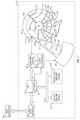
- FIG. 1is a block diagram of a magnetic recording hard disk drive (HDD) according to this invention.
- FIG. 2is a sectional view of a disk and associated read/write head illustrating the problem of adjacent track encroachment (ATE) during writing.
- ATEadjacent track encroachment
- FIG. 3is a graph of measured bit error rate (BER) degradation values for a range of tracks written by a perpendicular recording head.
- BERbit error rate
- FIG. 4is a table of track number, BER value, and calculated count increment for tracks within a range of tracks for the perpendicular write head that produced the BER data of FIG. 3 .
- FIG. 5is a graphical representation of the example of FIGS. 3-4 wherein the data tracks are grouped into data segments, each segment having 4 tracks.
- FIG. 1is a block diagram of a magnetic recording disk drive (HDD) 10 according to this invention.
- the HDD 10includes a hard disk controller (HDC) 12 that can include and/or be implemented by a microcontroller or microprocessor.
- the controller 12runs a computer program that is stored in memory 14 and that embodies the logic and algorithms described further below.
- the memory 14may be separate from controller 12 or as embedded memory on the controller chip.
- the computer programmay also be implemented in microcode or other type of memory accessible to the controller 12 .
- the controller 12is connected to a host interface 16 that communicates with the host computer 18 .
- the host computer 18may be a portable computer that can operate from battery power.
- the host interface 16may be any conventional computer-HDD interface, such as Serial ATA (Advanced Technology Attachment) or SCSI (Small Computer System Interface).
- the HDD 10typically includes a stack of disks 24 that are mounted on a spindle 23 and rotated by a spindle motor (not shown), with each disk surface being associated with one of the heads 22 .
- the read/write head 22is typically a combination of an inductive write head with a magnetoresistive read head and is located on the trailing end or end face of a head carrier or slider 30 .
- Slider 30is supported on the actuator arm 31 by a suspension 32 that enables the slider to “pitch” and “roll” on an air-bearing generated by the disk 24 as it rotates in the direction of arrow 130 .
- the actuator arm 31is attached to a rotary actuator 28 that rotates about pivot 29 .
- the path of slider 30 with attached read/write head 22is not aligned with a disk radius, but is an arcuate path (like that shown by servo sectors 120 described below).
- the end face of slider 30which supports the read/write head 22 , makes an angle (called the skew angle) with the disk radius, with the skew angle being a known function of disk radius and thus track number.
- the disk 24has radially-spaced concentric data tracks, one of which is shown as track 101 .
- Each data trackhas a reference index 121 indicating the start-of-track.
- the HDD 10is illustrated as a zone-bit-recording (ZBR) HDD because the data tracks are grouped radially into a number of annular data bands or zones, three of which are shown as zones 151 , 152 and 153 , but the invention is fully applicable to a HDD that does not use ZBR, in which case the HDD would have only a single data zone.
- the tracksare also circumferentially divided into a number of contiguous physical data sectors, such as typical data sectors 164 in the radially outer data zone.
- Each data sector 164is preceded by a synchronization (sync) field, such as typical sync fields 163 .
- the sync fields 163are detectable by the read head for enabling synchronization of reading and writing the data bits in the data sectors 164 .
- a sync field 163is a nondata region on the disk that is magnetized each time data is written in its associated data sector 164 .
- Each data trackalso includes a plurality of circumferentially or angularly-spaced servo sectors 120 that contain positioning information detectable by the read head for moving the head 22 to desired data tracks and maintaining the head 22 on the data tracks.
- the servo sectors in each trackare aligned circumferentially with the servo sectors in the other tracks so that they extend across the tracks in a generally radial direction, as represented by radially-directed servo sectors 120 .
- the servo sectors 120are nondata regions on the disk that are magnetized once, typically during manufacturing or formatting of the disk, and are not intended to be erased during normal operation of the HDD.
- each servo sector 120has a servo identification (SID) mark, also called a servo timing mark (STM), that indicates the beginning of the servo sector.
- SIDservo identification
- STMservo timing mark
- the electronics associated with HDD 10also include servo electronics 40 .
- the read/write channel 20receives signals from head 22 and passes servo information from the servo sectors 120 to servo electronics 40 and data signals from the data sectors 164 to controller 12 .
- Servo electronics 40typically includes a servo control processor that uses the servo information from the servo sectors 120 to run a control algorithm that produces a control signal. The control signal is converted to a current that drives actuator 28 to position the head 22 .
- interface 16receives a request from the host computer 18 for reading from or writing to the data sectors 164 .
- Controller 12receives a list of requested data sectors from interface 16 and converts them into a set of numbers that uniquely identify the disk surface, track and data sector. The numbers are passed to servo electronics 40 to enable positioning head 22 to the appropriate data sector 164 .
- the controller 12acts as a data controller to transfer blocks of write data from the host computer 18 through the read/write channel 20 for writing to the disks 24 by the heads 22 , and to transfer blocks of read data from the disks 24 back to the host computer 18 .
- HDDstypically include, in addition to the rotating disk storage, solid state memory (referred to as “cache”) that temporarily holds data before it is transferred between the host computer and the disk storage.
- the conventional cacheis dynamic random access memory (DRAM), a volatile form of memory that can undergo a significant number of write/erase cycles and that has a high data transfer rate. HDDs may also include nonvolatile memory.
- Flash memorywhich stores information in an array of floating gate transistors, called “cells” which can be electrically erased and reprogrammed in blocks.
- the controller 12also communicates with volatile memory 50 (shown as DRAM) and optional nonvolatile memory 52 (shown as FLASH) via data bus 54 .
- ATEadjacent track erasure
- FIG. 2is a sectional view of a disk 24 and associated read/write head 22 .
- the disk 24is shown with recording layer 24 ′ having written data tracks n ⁇ 1 to n+1.
- the write pole 60 of read/write head 22generates a magnetic write field 70 directed to track n aligned with pole 60 .
- the write pole 60may be the write pole of a perpendicular write head, meaning that the write field 70 magnetizes regions of the recording layer 24 ′ in the direction perpendicular to the recording layer 24 ′.
- the write field 70is generally wider than a data track so when the write pole 60 is writing to track n, the outer portions (called the fringe field) of the write field 70 overlap onto at least tracks n+1 and n ⁇ 1, the single tracks on either side of the track being written.
- This overlapis the ATE that will result in added noise and degradation of the data on the tracks n+1 and n ⁇ 1.
- ATEmay also occur in tracks more than one track, for example two tracks, away from the track being written.
- variable incremented countingis performed for the tracks subjected to the FTE effects.
- the magnitude or extent of the FTE effectis determined for each track within a range of tracks of the track being written, and based on the relative FTE effect for all the tracks in the range a count increment (CI) is determined for each track.
- a counteris maintained for each track, and when data is written to a track the counters are increased by the predetermined increments based on the number of tracks from the track being written.
- the count for a trackreaches a predetermined threshold, that track is read and then rewritten.
- the datais rewritten before the FTE effects can build up, so the reliability of the data is improved.
- the trackscan be grouped into segments, for example 4 tracks per segment, and all the tracks in a segment read and rewritten when a count threshold for a segment is reached. This will reduce the amount of memory required to store the counts for each track.
- the error rateis used to determine the count increments.
- a predetermined data patternis written to all the tracks within a range of ⁇ N to +N tracks from a track (designated track 0).
- An initial “bit” error rate (BER)is then measured for each track in the range of 2N tracks.
- the HDD's error correction circuitryis deactivated, for example by setting to zero the value in the error correction register for the maximum number of errors to correct, and then the data pattern is read back and the number of bytes in error is counted.
- FIG. 3is a graph of measured BER degradation values for a range of 32 tracks written by a perpendicular write head. The y-axis of FIG. 3 is the difference in the logarithm of the measured BER after writes and the logarithm of the initial BER ( ⁇ log (BER)). This graph shows the expected ATE effect at tracks ⁇ 1 and +1.
- FIG. 3also shows the unsymmetrical characteristic of FTE, with very low BER values for tracks between +2 and +16. From the measured BER degradation values, which represent the relative weightings of FTE for all the tracks within the range, a set of count increments can be calculated for all the tracks within the range.
- FIG. 4is a table of track number (TR#), BER degradation value (logarithmic), and calculated count increment (CI) for 32 tracks within a range of ⁇ 16 to +16 tracks for the perpendicular write head that produced the BER data of FIG. 3 .
- a count for each track within a range of the track being writtenis increased by its value of CI according to a table of CI values (for example, ⁇ 16 tracks to +16 tracks in the table of FIG. 4 ).
- the controller(HDC 12 in FIG. 1 ), or another controller or microprocessor in the HDD, identifies the track number where data is being written, recalls from the table the CI values for each track within the range and increases the counters for each track within the range by the recalled CI values.
- the table and the countersare stored in memory associated with controller 12 , for example memory 14 , which may be embedded in controller 12 , volatile memory 50 or nonvolatile memory 52 .
- TWhen the count value for a track reaches a predetermined threshold (T) the data is read from that track and rewritten, preferably to the same track.
- Tcan be chosen based on several factors, including the known track density of the HDD, the intended purpose of the HDD, the desired reliability, and the BER of the HDD measured during manufacturing. Thus, depending on these factors, T may be chosen to be a relatively high value, for example higher than 10,000, or a relatively low value, for example less than several hundred.
- a table like that in FIG. 4can be developed for each head and its associated disk surface. Also, because of head skew, the write profile and thus the FTE effects for a particular head may vary depending on the radial position of the head. Thus multiple tables like the table in FIG. 4 may be maintained for each head, depending on the radial position of the head. For example, in a ZBR HDD like that shown in FIG. 1 , a table may be maintained for each data zone.
- the inventionhas been described above for an implementation where there is a counter for each data track. Because HDDs may have a large number of tracks, e.g., several hundred thousand, a significant amount of memory may be required to store the counts for each track. Thus in a modification of the invention the tracks can be grouped into multiple-track data segments, where each segment is within a range of the segment containing the track being written, and each segment has an associated predetermined count increment. When the count for a segment reaches a predetermined threshold, all the tracks in that segment are read and then rewritten.
- Segment 0corresponds to tracks ⁇ 1 to +3 in the table of FIG. 4 and thus segment 0 has a CI of 5 (the sum of the CI values for tracks ⁇ 1 to +3 in the table of FIG. 4 ).
- the CI for each segmentis thus related to the sum of the BER degradation values for all the tracks in the segment.
- the downward arrowrepresents the track being written, which is track 1 of segment 0, where the tracks in each segment are numbered from 0 to M ⁇ 1.
- segment ⁇ 2includes tracks ⁇ 7 to ⁇ 10 in the table of FIG. 4 and the count increment (CI) for segment ⁇ 2 is 28, which is the sum of the CI values for tracks ⁇ 7 to ⁇ 10. So the writing of track 1 in segment 0 would result in the count for segment ⁇ 2 being increased by a CI of 28.
- Segment ⁇ 2is now tracks ⁇ 9 to ⁇ 12, rather that tracks ⁇ 7 to ⁇ 10, from the track being written.
- this tablewould have a CI of 109, the sum of the CI values of tracks ⁇ 9 to ⁇ 12. So the writing of track 3 in segment 0 would result in the count for segment ⁇ 2 being increased by a CI of 109.
- the controller(HDC 12 in FIG. 1 ), identifies the track number where data is being written and thus the segment number and the track number within that segment, determines which table to select for access, recalls from the selected table the CI values for each segment within the range of the segment containing the track where data is to be written, and increases the counters for each segment within the range by the recalled CI values.
- the table and the countersare stored in memory associated with controller 12 , for example memory 14 , which may be embedded in controller 12 , volatile memory 50 or nonvolatile memory 52 .
- Tpredetermined threshold
- the operation of the HDD as described abovemay be implemented as a set of computer program instructions stored in memory and executable by a processor, such as the HDC, or a separate controller or microprocessor in the HDD.
- the controllerperforms logical and arithmetic operations based on the program instructions stored in memory, and is thus capable of performing the functions described above and represented in the figures.
Landscapes
- Engineering & Computer Science (AREA)
- Signal Processing (AREA)
- Signal Processing For Digital Recording And Reproducing (AREA)
- Digital Magnetic Recording (AREA)
Abstract
Description
CITR#=10[Δ log(BER
Claims (14)
Priority Applications (2)
| Application Number | Priority Date | Filing Date | Title |
|---|---|---|---|
| US12/839,391US8531793B2 (en) | 2010-07-19 | 2010-07-19 | Disk drive with variable incremented counting of writes to the data tracks for minimizing the effect of far track erasure |
| JP2011156367AJP2012028002A (en) | 2010-07-19 | 2011-07-15 | Disk drive with variable incremented counting means of writing to data track for minimizing effect of far track erasure |
Applications Claiming Priority (1)
| Application Number | Priority Date | Filing Date | Title |
|---|---|---|---|
| US12/839,391US8531793B2 (en) | 2010-07-19 | 2010-07-19 | Disk drive with variable incremented counting of writes to the data tracks for minimizing the effect of far track erasure |
Publications (2)
| Publication Number | Publication Date |
|---|---|
| US20120014013A1 US20120014013A1 (en) | 2012-01-19 |
| US8531793B2true US8531793B2 (en) | 2013-09-10 |
Family
ID=45466804
Family Applications (1)
| Application Number | Title | Priority Date | Filing Date |
|---|---|---|---|
| US12/839,391Expired - Fee RelatedUS8531793B2 (en) | 2010-07-19 | 2010-07-19 | Disk drive with variable incremented counting of writes to the data tracks for minimizing the effect of far track erasure |
Country Status (2)
| Country | Link |
|---|---|
| US (1) | US8531793B2 (en) |
| JP (1) | JP2012028002A (en) |
Cited By (27)
| Publication number | Priority date | Publication date | Assignee | Title |
|---|---|---|---|---|
| US20130318295A1 (en)* | 2012-05-23 | 2013-11-28 | Kabushiki Kaisha Toshiba | Disk storage apparatus and write method |
| US8908308B1 (en) | 2013-11-26 | 2014-12-09 | Seagate Technology Llc | Adaptive passive data track erasure healing |
| US8941935B1 (en)* | 2014-03-10 | 2015-01-27 | HGST Netherlands B.V. | System and method for initiating refresh operations |
| US9129658B1 (en)* | 2014-05-07 | 2015-09-08 | Kabushiki Kaisha Toshiba | Magnetic disk drive and method for controlling data rewrite |
| US9153247B1 (en) | 2015-01-21 | 2015-10-06 | HGST Netherlands B.V. | Far field interference mitigation by relative frequency ordering |
| US9324362B1 (en) | 2014-11-24 | 2016-04-26 | Seagate Technology Llc | Post-write scan operations for interlaced magnetic recording |
| US9330701B1 (en) | 2014-12-15 | 2016-05-03 | Seagate Technology Llc | Dynamic track misregistration dependent error scans |
| US9336818B1 (en) | 2015-02-04 | 2016-05-10 | HGST Netherlands B.V. | Method for reducing adjacent track interference effects in a data storage system |
| US9508362B2 (en) | 2014-11-24 | 2016-11-29 | Seagate Technology Llc | Write management for interlaced magnetic recording devices |
| US9524743B2 (en) | 2014-11-24 | 2016-12-20 | Seagate Technology Llc | Heat assisted magnetic recording for bit-patterned media |
| US9576604B1 (en)* | 2015-08-27 | 2017-02-21 | Kabushiki Kaisha Toshiba | Magnetic disk device and write control method |
| US9601154B2 (en) | 2014-11-24 | 2017-03-21 | Seagate Technology Llc | Prioritized random access for magnetic recording |
| US9672851B1 (en) | 2016-05-04 | 2017-06-06 | Seagate Technology Llc | Single writer interlaced magnetic recording |
| US9747942B2 (en) | 2014-11-24 | 2017-08-29 | Seagate Technology Llc | Variable written track widths for attribute-based storage |
| US9773517B2 (en) | 2014-11-24 | 2017-09-26 | Seagate Technology Llc | Dual writer head design |
| US9805744B1 (en) | 2016-04-01 | 2017-10-31 | Seagate Technology Llc | Dual writer design in interlaced magnetic recording |
| US9805741B1 (en) | 2016-01-29 | 2017-10-31 | Seagate Technology Llc | Write current parameter selection for magnetic recording |
| US9818445B2 (en) | 2016-01-12 | 2017-11-14 | Seagate Technology Llc | Magnetic storage device readers |
| US9842047B2 (en) | 2014-11-24 | 2017-12-12 | Seagate Technology Llc | Non-sequential write for sequential read back |
| US10199066B1 (en) | 2018-03-01 | 2019-02-05 | Seagate Technology Llc | Write management of physically coupled storage areas |
| US10210891B1 (en) | 2016-01-28 | 2019-02-19 | Seagate Technology Llc | Dual writer head design utilizing two writers of different sizes for writing interlaced data tracks |
| US10846955B2 (en) | 2018-03-16 | 2020-11-24 | Micron Technology, Inc. | Black box data recorder for autonomous driving vehicle |
| US11094148B2 (en)* | 2018-06-18 | 2021-08-17 | Micron Technology, Inc. | Downloading system memory data in response to event detection |
| US11373466B2 (en) | 2019-01-31 | 2022-06-28 | Micron Technology, Inc. | Data recorders of autonomous vehicles |
| US11410475B2 (en) | 2019-01-31 | 2022-08-09 | Micron Technology, Inc. | Autonomous vehicle data recorders |
| US11561729B2 (en) | 2020-08-19 | 2023-01-24 | Micron Technology, Inc. | Write determination counter |
| US11782605B2 (en) | 2018-11-29 | 2023-10-10 | Micron Technology, Inc. | Wear leveling for non-volatile memory using data write counters |
Families Citing this family (9)
| Publication number | Priority date | Publication date | Assignee | Title |
|---|---|---|---|---|
| US8810941B2 (en) | 2012-07-10 | 2014-08-19 | HGST Netherlands B.V. | System, method and apparatus for selection of reserved area data tracks |
| US9055711B2 (en) | 2012-07-16 | 2015-06-09 | HGST Netherlands B.V. | System and method for maintaining data integrity on a storage medium |
| US8879180B2 (en) | 2012-12-12 | 2014-11-04 | HGST Netherlands B.V. | System, method and apparatus for data track usage sequence to reduce adjacent track interference effect |
| US9110841B1 (en)* | 2013-03-15 | 2015-08-18 | Seagate Technology Llc | Overlap detection using bitmask region trackers |
| US9390751B1 (en) | 2015-10-07 | 2016-07-12 | HGST Netherlands B.V. | Reducing overcounting of track-level damage caused by adjacent-track and far-track interference |
| US9997192B1 (en) | 2017-05-18 | 2018-06-12 | Seagate Technology Llc | Overlap detection for magnetic disks |
| US11733873B2 (en) | 2017-12-01 | 2023-08-22 | Micron Technology, Inc. | Wear leveling in solid state drives |
| US10418062B2 (en)* | 2017-12-19 | 2019-09-17 | International Business Machines Corporation | Efficient rewrite using larger codeword sizes |
| JP2019160376A (en)* | 2018-03-15 | 2019-09-19 | 株式会社東芝 | Magnetic disc device, and refresh processing method |
Citations (19)
| Publication number | Priority date | Publication date | Assignee | Title |
|---|---|---|---|---|
| US5600500A (en) | 1994-11-14 | 1997-02-04 | Seagate Technology, Inc. | Performance based write current optimization process |
| US6442705B1 (en) | 1999-04-26 | 2002-08-27 | International Business Machines Corporation | Method of and apparatus for improving data integrity in a disk drive system |
| US6947234B2 (en) | 2002-07-23 | 2005-09-20 | International Business Machines Corporation | Method, system, and program for performing error correction in a storage device having a magnetic storage medium |
| US20060066971A1 (en) | 2004-09-30 | 2006-03-30 | Hitachi Global Storage Technologies Netherlands B.V. | System and method for ameliorating the effects of adjacent track erasure in magnetic data storage device |
| US7177979B2 (en)* | 2003-03-11 | 2007-02-13 | Hitachi Global Storage Technologies Japan, Ltd. | Method for preventing data loss due to repeated writes to a given track on a magnetic disk drive |
| US7227708B2 (en) | 2004-11-10 | 2007-06-05 | Hitachi Global Storage Technologies Netherlands B.V. | System and method for determining long-range erasure of adjacent tracks in hard disk drive |
| US7245447B2 (en)* | 2003-03-28 | 2007-07-17 | Hitachi Global Storage Technologies Japan, Ltd. | Magnetic read/write apparatus having a write inhibit slice setting circuit |
| US7345837B1 (en)* | 2004-12-02 | 2008-03-18 | Maxtor Corporation | Disk drive that refreshes data on portions of a disk based on a number of write operations thereto |
| US7463441B2 (en)* | 2004-01-30 | 2008-12-09 | Samsung Electronics Co., Ltd. | Automatic data update method of data storage system and disk drive using the same |
| US20090091861A1 (en) | 2007-10-03 | 2009-04-09 | Headway Technologies, Inc. | Perpendicular magnetic recording write head with a side shield |
| US7525748B2 (en)* | 2006-03-06 | 2009-04-28 | Fujitsu Limited | Information recording/reproducing apparatus |
| US7567400B2 (en) | 2005-04-27 | 2009-07-28 | Hitachi Global Storage Technologies Netherlands B.V. | Method and apparatus for improving the error rate of track information on a magnetic storage device |
| US20090244775A1 (en) | 2008-03-31 | 2009-10-01 | Kabushiki Kaisha Toshiba 1-1 | Adjacent-track-erasure (ate) refresh with increased track resolution for often-written areas |
| US7920352B2 (en)* | 2008-02-28 | 2011-04-05 | Toshiba Storage Device Corporation | Magnetic disk apparatus and data storage method |
| US7945727B2 (en)* | 2007-07-27 | 2011-05-17 | Western Digital Technologies, Inc. | Disk drive refreshing zones in segments to sustain target throughput of host commands |
| US7974029B2 (en)* | 2009-07-31 | 2011-07-05 | Western Digital Technologies, Inc. | Disk drive biasing refresh zone counters based on write commands |
| US8014097B1 (en)* | 2010-05-07 | 2011-09-06 | Hitachi Global Storage Technologies Netherlands B.V. | Disk drive with adaptive counting of writes to the data tracks for minimizing the effect of adjacent track encroachment |
| US8068299B2 (en)* | 2007-03-26 | 2011-11-29 | Hitachi Global Storage Technologies, Netherlands B.V. | Disk drive device and data rewrite method thereof |
| US8331053B2 (en)* | 2009-09-25 | 2012-12-11 | Lenovo (Singapore) Pte. Ltd. | Systems and methods for adjacent track interference (ATI) risk management |
- 2010
- 2010-07-19USUS12/839,391patent/US8531793B2/ennot_activeExpired - Fee Related
- 2011
- 2011-07-15JPJP2011156367Apatent/JP2012028002A/ennot_activeWithdrawn
Patent Citations (19)
| Publication number | Priority date | Publication date | Assignee | Title |
|---|---|---|---|---|
| US5600500A (en) | 1994-11-14 | 1997-02-04 | Seagate Technology, Inc. | Performance based write current optimization process |
| US6442705B1 (en) | 1999-04-26 | 2002-08-27 | International Business Machines Corporation | Method of and apparatus for improving data integrity in a disk drive system |
| US6947234B2 (en) | 2002-07-23 | 2005-09-20 | International Business Machines Corporation | Method, system, and program for performing error correction in a storage device having a magnetic storage medium |
| US7177979B2 (en)* | 2003-03-11 | 2007-02-13 | Hitachi Global Storage Technologies Japan, Ltd. | Method for preventing data loss due to repeated writes to a given track on a magnetic disk drive |
| US7245447B2 (en)* | 2003-03-28 | 2007-07-17 | Hitachi Global Storage Technologies Japan, Ltd. | Magnetic read/write apparatus having a write inhibit slice setting circuit |
| US7463441B2 (en)* | 2004-01-30 | 2008-12-09 | Samsung Electronics Co., Ltd. | Automatic data update method of data storage system and disk drive using the same |
| US20060066971A1 (en) | 2004-09-30 | 2006-03-30 | Hitachi Global Storage Technologies Netherlands B.V. | System and method for ameliorating the effects of adjacent track erasure in magnetic data storage device |
| US7227708B2 (en) | 2004-11-10 | 2007-06-05 | Hitachi Global Storage Technologies Netherlands B.V. | System and method for determining long-range erasure of adjacent tracks in hard disk drive |
| US7345837B1 (en)* | 2004-12-02 | 2008-03-18 | Maxtor Corporation | Disk drive that refreshes data on portions of a disk based on a number of write operations thereto |
| US7567400B2 (en) | 2005-04-27 | 2009-07-28 | Hitachi Global Storage Technologies Netherlands B.V. | Method and apparatus for improving the error rate of track information on a magnetic storage device |
| US7525748B2 (en)* | 2006-03-06 | 2009-04-28 | Fujitsu Limited | Information recording/reproducing apparatus |
| US8068299B2 (en)* | 2007-03-26 | 2011-11-29 | Hitachi Global Storage Technologies, Netherlands B.V. | Disk drive device and data rewrite method thereof |
| US7945727B2 (en)* | 2007-07-27 | 2011-05-17 | Western Digital Technologies, Inc. | Disk drive refreshing zones in segments to sustain target throughput of host commands |
| US20090091861A1 (en) | 2007-10-03 | 2009-04-09 | Headway Technologies, Inc. | Perpendicular magnetic recording write head with a side shield |
| US7920352B2 (en)* | 2008-02-28 | 2011-04-05 | Toshiba Storage Device Corporation | Magnetic disk apparatus and data storage method |
| US20090244775A1 (en) | 2008-03-31 | 2009-10-01 | Kabushiki Kaisha Toshiba 1-1 | Adjacent-track-erasure (ate) refresh with increased track resolution for often-written areas |
| US7974029B2 (en)* | 2009-07-31 | 2011-07-05 | Western Digital Technologies, Inc. | Disk drive biasing refresh zone counters based on write commands |
| US8331053B2 (en)* | 2009-09-25 | 2012-12-11 | Lenovo (Singapore) Pte. Ltd. | Systems and methods for adjacent track interference (ATI) risk management |
| US8014097B1 (en)* | 2010-05-07 | 2011-09-06 | Hitachi Global Storage Technologies Netherlands B.V. | Disk drive with adaptive counting of writes to the data tracks for minimizing the effect of adjacent track encroachment |
Non-Patent Citations (3)
| Title |
|---|
| D. Guarisco et al., "A Fast and Accurate Method for Measuring Adjacent-Track Erasure", IEEE Transactions on Magnetics, vol. 42, No. 12, Dec. 2006, pp. 3868-3873. |
| Li et al., "Adjacent Track Erasure Analysis and Modeling at High Track Density", IEEE Transactions on Magnetics, vol. 39, No. 5, Sep. 2003, pp. 2627-2629. |
| Y. Liu et al., "Characterization of Skip or Far Track Erasure in a Side Shield Design", IEEE Transactions on Magnetics, vol. 45, No. 10, Oct. 2009, pp. 3660-3663. |
Cited By (45)
| Publication number | Priority date | Publication date | Assignee | Title |
|---|---|---|---|---|
| US20130318295A1 (en)* | 2012-05-23 | 2013-11-28 | Kabushiki Kaisha Toshiba | Disk storage apparatus and write method |
| US9087551B2 (en)* | 2012-05-23 | 2015-07-21 | Kabushiki Kaisha Toshiba | Disk storage apparatus and write method |
| US8908308B1 (en) | 2013-11-26 | 2014-12-09 | Seagate Technology Llc | Adaptive passive data track erasure healing |
| US8941935B1 (en)* | 2014-03-10 | 2015-01-27 | HGST Netherlands B.V. | System and method for initiating refresh operations |
| US9129658B1 (en)* | 2014-05-07 | 2015-09-08 | Kabushiki Kaisha Toshiba | Magnetic disk drive and method for controlling data rewrite |
| US9601154B2 (en) | 2014-11-24 | 2017-03-21 | Seagate Technology Llc | Prioritized random access for magnetic recording |
| US9747942B2 (en) | 2014-11-24 | 2017-08-29 | Seagate Technology Llc | Variable written track widths for attribute-based storage |
| US9858961B2 (en) | 2014-11-24 | 2018-01-02 | Seagate Technology Llc | Reader design for interlaced magnetic recording |
| US10049698B2 (en) | 2014-11-24 | 2018-08-14 | Seagate Technology Llc | Interlaced magnetic recording super parity |
| US9508362B2 (en) | 2014-11-24 | 2016-11-29 | Seagate Technology Llc | Write management for interlaced magnetic recording devices |
| US9524743B2 (en) | 2014-11-24 | 2016-12-20 | Seagate Technology Llc | Heat assisted magnetic recording for bit-patterned media |
| US9773517B2 (en) | 2014-11-24 | 2017-09-26 | Seagate Technology Llc | Dual writer head design |
| US9842047B2 (en) | 2014-11-24 | 2017-12-12 | Seagate Technology Llc | Non-sequential write for sequential read back |
| US9607631B2 (en) | 2014-11-24 | 2017-03-28 | Seagate Technology Llc | Enhanced capacity recording |
| US9633675B2 (en) | 2014-11-24 | 2017-04-25 | Seagate Technology Llc | Interlaced magnetic recording super parity |
| US10090016B2 (en) | 2014-11-24 | 2018-10-02 | Seagate Technology Llc | Variable written track widths for attribute-based storage |
| US9672845B2 (en) | 2014-11-24 | 2017-06-06 | Seagate Technology Llc | Adjacent track interference asymmetry mitigation |
| US9679601B2 (en) | 2014-11-24 | 2017-06-13 | Seagate Technology Llc | Post-write scan operations for interlaced magnetic recording |
| US9728206B2 (en) | 2014-11-24 | 2017-08-08 | Seagate Technology Llc | Interlaced magnetic recording |
| US9741364B2 (en) | 2014-11-24 | 2017-08-22 | Seagate Technology Llc | Laser power optimization for heat assisted interlaced magnetic recording |
| US9741363B2 (en) | 2014-11-24 | 2017-08-22 | Seagate Technology Llc | Laser power optimization for heat assisted interlaced magnetic recording |
| US9324362B1 (en) | 2014-11-24 | 2016-04-26 | Seagate Technology Llc | Post-write scan operations for interlaced magnetic recording |
| US9747943B2 (en) | 2014-11-24 | 2017-08-29 | Seagate Technology Llc | Prioritized random access for magnetic recording |
| US9330701B1 (en) | 2014-12-15 | 2016-05-03 | Seagate Technology Llc | Dynamic track misregistration dependent error scans |
| US9153247B1 (en) | 2015-01-21 | 2015-10-06 | HGST Netherlands B.V. | Far field interference mitigation by relative frequency ordering |
| US9336818B1 (en) | 2015-02-04 | 2016-05-10 | HGST Netherlands B.V. | Method for reducing adjacent track interference effects in a data storage system |
| US9576604B1 (en)* | 2015-08-27 | 2017-02-21 | Kabushiki Kaisha Toshiba | Magnetic disk device and write control method |
| US9818445B2 (en) | 2016-01-12 | 2017-11-14 | Seagate Technology Llc | Magnetic storage device readers |
| US10210891B1 (en) | 2016-01-28 | 2019-02-19 | Seagate Technology Llc | Dual writer head design utilizing two writers of different sizes for writing interlaced data tracks |
| US9805741B1 (en) | 2016-01-29 | 2017-10-31 | Seagate Technology Llc | Write current parameter selection for magnetic recording |
| US9805744B1 (en) | 2016-04-01 | 2017-10-31 | Seagate Technology Llc | Dual writer design in interlaced magnetic recording |
| US9672851B1 (en) | 2016-05-04 | 2017-06-06 | Seagate Technology Llc | Single writer interlaced magnetic recording |
| US10199066B1 (en) | 2018-03-01 | 2019-02-05 | Seagate Technology Llc | Write management of physically coupled storage areas |
| US10482919B2 (en) | 2018-03-01 | 2019-11-19 | Seagate Technology Llc | Write management of physically coupled storage areas |
| US11676431B2 (en) | 2018-03-16 | 2023-06-13 | Micron Technology, Inc. | Black box data recorder for autonomous driving vehicle |
| US10846955B2 (en) | 2018-03-16 | 2020-11-24 | Micron Technology, Inc. | Black box data recorder for autonomous driving vehicle |
| US12087110B2 (en) | 2018-03-16 | 2024-09-10 | Lodestar Licensing Group Llc | Black box data recorder for autonomous driving vehicle |
| US11094148B2 (en)* | 2018-06-18 | 2021-08-17 | Micron Technology, Inc. | Downloading system memory data in response to event detection |
| US11756353B2 (en) | 2018-06-18 | 2023-09-12 | Micron Technology, Inc. | Downloading system memory data in response to event detection |
| US11782605B2 (en) | 2018-11-29 | 2023-10-10 | Micron Technology, Inc. | Wear leveling for non-volatile memory using data write counters |
| US11670124B2 (en) | 2019-01-31 | 2023-06-06 | Micron Technology, Inc. | Data recorders of autonomous vehicles |
| US11410475B2 (en) | 2019-01-31 | 2022-08-09 | Micron Technology, Inc. | Autonomous vehicle data recorders |
| US11373466B2 (en) | 2019-01-31 | 2022-06-28 | Micron Technology, Inc. | Data recorders of autonomous vehicles |
| US11561729B2 (en) | 2020-08-19 | 2023-01-24 | Micron Technology, Inc. | Write determination counter |
| US12147708B2 (en) | 2020-08-19 | 2024-11-19 | Micron Technology, Inc. | Write determination counter |
Also Published As
| Publication number | Publication date |
|---|---|
| JP2012028002A (en) | 2012-02-09 |
| US20120014013A1 (en) | 2012-01-19 |
Similar Documents
| Publication | Publication Date | Title |
|---|---|---|
| US8531793B2 (en) | Disk drive with variable incremented counting of writes to the data tracks for minimizing the effect of far track erasure | |
| US8537481B1 (en) | Shingled magnetic recording disk drive with minimization of the effect of far track erasure on adjacent data bands | |
| US8793431B2 (en) | Shingled magnetic recording disk drive with inter-band disk cache and minimization of the effect of far track erasure on adjacent data bands | |
| US8593748B1 (en) | Shingled magnetic recording disk drive with compensation for the effect of far track erasure (FTE) on adjacent data bands | |
| US8699162B1 (en) | Shingled magnetic recording disk drive with multiple data zones containing different numbers of error-correction-code sectors | |
| US8014097B1 (en) | Disk drive with adaptive counting of writes to the data tracks for minimizing the effect of adjacent track encroachment | |
| US8665545B2 (en) | Shingled magnetic recording (SMR) disk drive with verification of written data | |
| US10049698B2 (en) | Interlaced magnetic recording super parity | |
| US6972922B1 (en) | Disk drive having internal data structures for efficiently storing repeatable runout cancellation information | |
| US7599139B1 (en) | Disk drive having a high performance access mode and a lower performance archive mode | |
| US8724248B2 (en) | Method and apparatus for compensating vibration by adjusting track pitch | |
| US8599510B1 (en) | Disk drive adjusting data track density based on write condition when writing to contiguous data tracks | |
| US7567400B2 (en) | Method and apparatus for improving the error rate of track information on a magnetic storage device | |
| JP2009245577A (en) | Adjacent-track-erasure (ate) refresh with increased track resolution for often-written area | |
| US9070378B2 (en) | Partial write system | |
| US9378763B1 (en) | Track offset compensation in shingled recording | |
| US9349400B1 (en) | Magnetic recording disk drive with adjustable data track pitch and compensation for repeatable runout (RRO) | |
| KR100464440B1 (en) | Method for managing defects of disc drive, recording media therefor and disc drive therefor | |
| JP2009230846A (en) | Low track per inch (tpi) zone, in which necessity of adjacent track erasure (ate) refreshing is reduced | |
| US8755142B2 (en) | Magnetic recording disk drive with method for data preservation during high track misregistration (TMR) environment | |
| US20120081810A1 (en) | Magnetic disk drive using offset in positioning head to read data and head positioning method | |
| US6556369B1 (en) | Disk drive device with a high frequency access method and apparatus | |
| US9837111B1 (en) | Direct current magnetoresistive jog offset compensation | |
| US9412403B1 (en) | Magnetic recording disk drive with position error signal (PES) blocks in the data tracks for compensation of track misregistration | |
| US9064504B1 (en) | Electronic system with media recovery mechanism and method of operation thereof |
Legal Events
| Date | Code | Title | Description |
|---|---|---|---|
| AS | Assignment | Owner name:HITACHI GLOBAL STORAGE TECHNOLOGIES NETHERLANDS B. Free format text:ASSIGNMENT OF ASSIGNORS INTEREST;ASSIGNORS:BANDIC, ZVONIMIR Z.;SANVIDO, MARCO;WILSON, BRUCE ALEXANDER;REEL/FRAME:024709/0038 Effective date:20100715 | |
| AS | Assignment | Owner name:HGST, NETHERLANDS B.V., NETHERLANDS Free format text:CHANGE OF NAME;ASSIGNOR:HGST, NETHERLANDS B.V.;REEL/FRAME:029341/0777 Effective date:20120723 Owner name:HGST NETHERLANDS B.V., NETHERLANDS Free format text:CHANGE OF NAME;ASSIGNOR:HITACHI GLOBAL STORAGE TECHNOLOGIES NETHERLANDS B.V.;REEL/FRAME:029341/0777 Effective date:20120723 | |
| FEPP | Fee payment procedure | Free format text:PAYOR NUMBER ASSIGNED (ORIGINAL EVENT CODE: ASPN); ENTITY STATUS OF PATENT OWNER: LARGE ENTITY | |
| STCF | Information on status: patent grant | Free format text:PATENTED CASE | |
| AS | Assignment | Owner name:WESTERN DIGITAL TECHNOLOGIES, INC., CALIFORNIA Free format text:ASSIGNMENT OF ASSIGNORS INTEREST;ASSIGNOR:HGST NETHERLANDS B.V.;REEL/FRAME:040826/0327 Effective date:20160831 | |
| FPAY | Fee payment | Year of fee payment:4 | |
| AS | Assignment | Owner name:JPMORGAN CHASE BANK, N.A., AS AGENT, ILLINOIS Free format text:SECURITY INTEREST;ASSIGNOR:WESTERN DIGITAL TECHNOLOGIES, INC.;REEL/FRAME:052915/0566 Effective date:20200113 | |
| MAFP | Maintenance fee payment | Free format text:PAYMENT OF MAINTENANCE FEE, 8TH YEAR, LARGE ENTITY (ORIGINAL EVENT CODE: M1552); ENTITY STATUS OF PATENT OWNER: LARGE ENTITY Year of fee payment:8 | |
| AS | Assignment | Owner name:WESTERN DIGITAL TECHNOLOGIES, INC., CALIFORNIA Free format text:RELEASE OF SECURITY INTEREST AT REEL 052915 FRAME 0566;ASSIGNOR:JPMORGAN CHASE BANK, N.A.;REEL/FRAME:059127/0001 Effective date:20220203 | |
| AS | Assignment | Owner name:JPMORGAN CHASE BANK, N.A., ILLINOIS Free format text:PATENT COLLATERAL AGREEMENT - A&R LOAN AGREEMENT;ASSIGNOR:WESTERN DIGITAL TECHNOLOGIES, INC.;REEL/FRAME:064715/0001 Effective date:20230818 Owner name:JPMORGAN CHASE BANK, N.A., ILLINOIS Free format text:PATENT COLLATERAL AGREEMENT - DDTL LOAN AGREEMENT;ASSIGNOR:WESTERN DIGITAL TECHNOLOGIES, INC.;REEL/FRAME:067045/0156 Effective date:20230818 | |
| FEPP | Fee payment procedure | Free format text:MAINTENANCE FEE REMINDER MAILED (ORIGINAL EVENT CODE: REM.); ENTITY STATUS OF PATENT OWNER: LARGE ENTITY |