US8531414B2 - Bump suppression - Google Patents
Bump suppressionDownload PDFInfo
- Publication number
- US8531414B2 US8531414B2US12/730,091US73009110AUS8531414B2US 8531414 B2US8531414 B2US 8531414B2US 73009110 AUS73009110 AUS 73009110AUS 8531414 B2US8531414 B2US 8531414B2
- Authority
- US
- United States
- Prior art keywords
- event
- touch
- accelerometer
- delayed
- block
- Prior art date
- Legal status (The legal status is an assumption and is not a legal conclusion. Google has not performed a legal analysis and makes no representation as to the accuracy of the status listed.)
- Active, expires
Links
Images


Classifications
- G—PHYSICS
- G06—COMPUTING OR CALCULATING; COUNTING
- G06F—ELECTRIC DIGITAL DATA PROCESSING
- G06F3/00—Input arrangements for transferring data to be processed into a form capable of being handled by the computer; Output arrangements for transferring data from processing unit to output unit, e.g. interface arrangements
- G06F3/01—Input arrangements or combined input and output arrangements for interaction between user and computer
- G06F3/048—Interaction techniques based on graphical user interfaces [GUI]
- G06F3/0487—Interaction techniques based on graphical user interfaces [GUI] using specific features provided by the input device, e.g. functions controlled by the rotation of a mouse with dual sensing arrangements, or of the nature of the input device, e.g. tap gestures based on pressure sensed by a digitiser
- G06F3/0488—Interaction techniques based on graphical user interfaces [GUI] using specific features provided by the input device, e.g. functions controlled by the rotation of a mouse with dual sensing arrangements, or of the nature of the input device, e.g. tap gestures based on pressure sensed by a digitiser using a touch-screen or digitiser, e.g. input of commands through traced gestures
- G06F3/04883—Interaction techniques based on graphical user interfaces [GUI] using specific features provided by the input device, e.g. functions controlled by the rotation of a mouse with dual sensing arrangements, or of the nature of the input device, e.g. tap gestures based on pressure sensed by a digitiser using a touch-screen or digitiser, e.g. input of commands through traced gestures for inputting data by handwriting, e.g. gesture or text
- G—PHYSICS
- G06—COMPUTING OR CALCULATING; COUNTING
- G06F—ELECTRIC DIGITAL DATA PROCESSING
- G06F3/00—Input arrangements for transferring data to be processed into a form capable of being handled by the computer; Output arrangements for transferring data from processing unit to output unit, e.g. interface arrangements
- G06F3/01—Input arrangements or combined input and output arrangements for interaction between user and computer
- G06F3/03—Arrangements for converting the position or the displacement of a member into a coded form
- G06F3/041—Digitisers, e.g. for touch screens or touch pads, characterised by the transducing means
- G06F3/0416—Control or interface arrangements specially adapted for digitisers
- G06F3/0418—Control or interface arrangements specially adapted for digitisers for error correction or compensation, e.g. based on parallax, calibration or alignment
- G06F3/04186—Touch location disambiguation
- G—PHYSICS
- G06—COMPUTING OR CALCULATING; COUNTING
- G06F—ELECTRIC DIGITAL DATA PROCESSING
- G06F2203/00—Indexing scheme relating to G06F3/00 - G06F3/048
- G06F2203/041—Indexing scheme relating to G06F3/041 - G06F3/045
- G06F2203/04106—Multi-sensing digitiser, i.e. digitiser using at least two different sensing technologies simultaneously or alternatively, e.g. for detecting pen and finger, for saving power or for improving position detection
- H—ELECTRICITY
- H04—ELECTRIC COMMUNICATION TECHNIQUE
- H04M—TELEPHONIC COMMUNICATION
- H04M2250/00—Details of telephonic subscriber devices
- H04M2250/12—Details of telephonic subscriber devices including a sensor for measuring a physical value, e.g. temperature or motion
- H—ELECTRICITY
- H04—ELECTRIC COMMUNICATION TECHNIQUE
- H04M—TELEPHONIC COMMUNICATION
- H04M2250/00—Details of telephonic subscriber devices
- H04M2250/22—Details of telephonic subscriber devices including a touch pad, a touch sensor or a touch detector
Definitions
- the disclosureis generally related to the field of gesture-based input to electronic devices.
- a new form of human—device interactionallows users to communicate their intentions by shaking, tilting or waving a device.
- This style of inputrelies on sensors such as accelerometers and gyroscopes to sense motion.
- Some car racing gamesuse gyro sensors to let a user steer a car by tilting a smart phone running the game program, for example.
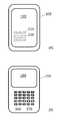
- FIGS. 1A and Bshow examples of mobile devices having touch screens and/or buttons.
- FIG. 2shows a mobile device with various physical sensors.
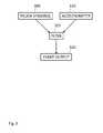
- FIG. 3is a diagram showing a touch sensor and an accelerometer connected to a filter that provides event output.
- FIGS. 4 ( a ) and ( b )show examples of event filtering.
- FIG. 4 ( c )shows a timeline showing an example of events processed by the filter of FIG. 4 ( b ).
- FIG. 5 ( a )shows an example of event filtering.
- FIG. 5 ( b )shows a timeline showing an example of events processed by the filter of FIG. 5 ( a ).
- FIG. 6 ( a )shows an example of event filtering.
- FIGS. 6 ( b ) and ( c )show timelines showing examples of events processed by the filter of FIG. 6 ( a ).
- FIG. 7 ( a )shows an example of event filtering.
- FIGS. 7 ( b ) and ( c )are timelines showing examples of events processed by the filter of FIG. 7 ( a ).
- FIG. 8shows a system for filtering data provided by multiple sensors.
- Devicesmay sense bumps through accelerometer measurements. If an accelerometer is too sensitive, light jiggling, jostling or other miscellaneous movement may trigger an unintended bump. On the other hand, if an accelerometer not sensitive enough, a punch or a slam may be needed to trigger a bump. It turns out that the approximate sensitivity range for comfortable bumping is also a range that is sensitive to screen touches or button presses. Thus a device may misinterpret a screen touch or a button press as a bump.
- Accelerometer data and screen touch (or button press) datamay be sent to a filter, implemented in hardware or software, which improves the reliability of bump gestures.
- a filterimplemented in hardware or software, which improves the reliability of bump gestures.
- One filtering strategyis based mainly on timing relationships between bumps and screen touches: bump signatures are ignored if they occur during a screen touch.
- Other filter strategiesbased on light, proximity, gyro, heat or other sensors are also useful and may be combined with timing strategies as needed. Combining data from multiple physical sensors in a filter reduces the chance that user input to one sensor is inadvertently reported by another sensor, resulting in a misinterpreted gesture.
- FIGS. 1 A and Bshow examples of mobile devices having touch screens and/or buttons.
- mobile device 105has a touch screen 110 .
- Virtual buttons, such as 115 and 120are displayed on the screen.
- mobile device 155has a screen 160 and physical buttons, such as 165 and 170 .
- screen 160may also be a touch screen capable of displaying virtual buttons and detecting screen touches, and device 105 may also incorporate physical buttons.
- Touch eventsmay indicate the beginning (touch down), end (touch up) or other aspects of a touch.
- FIG. 2shows a mobile device with various physical sensors.
- mobile device 205contains an accelerometer 210 , one or more gyros 215 , a camera 220 , a microphone 225 , a position sensor 230 and a temperature sensor 235 .
- Accelerometer 210 and gyros 215may be micro-electromechanical (MEMS) devices and may provide measurements along one, two or three spatial axes.
- An accelerometerfor example, may provide acceleration measurements along x, y and/or z axes while a gyro may provide rate of change of pitch, roll and/or yaw.
- MEMSmicro-electromechanical
- Camera 220is a digital camera that may provide still and/or video images.
- Microphone 225may be a MEMS device and may provide mono or stereo sound sensing capability.
- Position sensor 230may be a global navigational satellite system (GNSS) receiver such as a GPS, GLONASS, Galileo, Compass, etc. receiver. Position sensor 230 may also incorporate cell tower triangulation and/or navigation by proximity to surveyed WiFi hotspots.
- Temperature sensor 235may include a digital thermometer.
- GNSSglobal navigational satellite system
- FIG. 3is a diagram showing a touch sensor and an accelerometer connected to a filter that provides event output.
- touch sensor(s) 305 and accelerometer 310send data to filter 315 .
- the filterinterprets the data and reports the occurrence of various events 320 .
- filter 315may determine whether or not a bump event has occurred in response to a bump gesture input, or whether or not a user touch input was intentional or inadvertent.
- Events 320are data that are used by applications running on a processor in a device.
- Filter 315may be implemented in hardware, for example in an application specific integrated circuit, or software, for example as a process or part of a process running on a processor.
- FIGS. 4 ( a ) and ( b )show examples of event filtering.
- FIG. 4 ( c )shows a timeline showing an example of events processed by the filter of FIG. 4 ( b ).
- touch sensor 405 and accelerometer 410send data to filter 415 .
- the output of the filteris data representing the existence of a bump event 420 .
- accelerometer event block 425uses accelerometer data to determine the existence of accelerometer events, labeled “A”.
- Touch data from touch sensor 405is interpreted as touch events labeled “B” in filter 415 .
- Decision block 430issues digital output indicating whether or not a bump has occurred by comparing events A and B.
- decision block 430declares a bump if event A occurs and events A and B are separated in time by at least time T 0 . Said another way, accelerometer event A will be interpreted as a bump as long as no touch event occurs less than time interval T 0 before or after it.
- accelerometer event block 425performs operations on raw accelerometer data to determine when accelerometer events occur.
- accelerometer event block 425might output an accelerometer event if the rate of change of acceleration (sometimes called “jerk”, “jolt”, “surge” or “lurch”) exceeds 100 g/sec after having been less than 100 g/sec for at least 100 milliseconds.
- rate of change of accelerationsometimes called “jerk”, “jolt”, “surge” or “lurch”
- gis the acceleration due to gravity near the earth's surface.
- accelerometer event block 425might output an accelerometer event if the rate of change of acceleration exceeds 60 g/sec after having been less than 100 g/sec for at least 250 milliseconds.
- the specific thresholds for rate of change of accelerationmay be tuned for a particular application by observing the fraction of misinterpreted bumps. Generally, too low jerk thresholds result in an excessive number of unintended bumps while too high jerk thresholds result in failure to detect bumps that are intended by users.
- the delay(e.g. “after having been less than 100 g/sec for at least 100 milliseconds”) may be useful to prevent erroneous multiple reporting of bump events.
- Other acceleration and/or delay criteriamay be used.
- FIG. 4 ( b )shows a filter that is similar to that shown in FIG. 4 ( a ).
- touch sensor 435 and accelerometer 440send data to filter 445 .
- the output of the filteris data representing the existence of a bump event 450 .
- accelerometer event block 455uses accelerometer data to determine the existence of accelerometer events, labeled “A”.
- Touch data from touch sensor 435is interpreted as touch events labeled “B” in filter 445 .
- Decision block 460issues digital output indicating whether or not a bump has occurred by comparing events A and B.
- decision block 430declares a bump if event A occurs and: (1) event A occurs at least time interval T 1 before event B, or (2) event A occurs at least time interval T 2 after event B. If time intervals T 1 and T 2 are the same, then the filter of FIG. 4 ( b ) has the same effect as that of FIG. 4 ( a ). Accelerometer event block 455 functions exactly the same as accelerometer event block 425 in FIG. 4 ( a ).
- FIG. 4 ( c )shows a timeline showing an example of events processed by the filter of FIG. 4 ( b ).
- Timeline 470shows touch event “B” followed by accelerometer event “A”.
- Event Aoccurs more than time interval T 2 later than event A.
- events A and Bmeet the criteria of decision block 460 and filter 445 reports a bump coincident with event A.
- processing delaysmay introduce a short time between event A and the reporting of a bump. If event A had occurred after event B, but only by a short time, less than T 2 , then filter 445 would not have reported a bump. Similarly, the filter does not report a bump if no accelerometer “A” event occurs.
- FIG. 5 ( a )shows an example of event filtering.
- FIG. 5 ( b )shows a timeline showing an example of events processed by the filter of FIG. 5 ( a ).
- FIGS. 5 ( a ) and 4 ( b )are similar. However, in FIG. 5 ( a ) “touch down” (“B 1 ”) and “touch up” (“B 2 ”) events are reported to a filter, rather than unspecific touch events. Touch down represents the moment that a screen touch or button press begins; touch up represents the moment that the touch or press ends. Many device operating systems report “touch down” or “touch up” events to applications.
- the filter illustrated in FIG. 5 ( a )also includes a time delay block, 527 .
- touch down sensor 505touch up sensor 507
- accelerometer 510send data to filter 515 .
- the output of the filteris data representing the existence of a bump event 520 .
- accelerometer event block 525uses accelerometer data to determine the existence of an accelerometer event. Accelerometer event block 525 functions exactly the same as accelerometer event block 425 in FIG. 4 ( a ).
- the accelerometer eventis delayed by time delay block 527 before being identified as event “A”.
- Touch down data from touch down sensor 505is interpreted as touch events labeled “B 1 ” in filter 515 .
- Touch up data from touch up sensor 507is interpreted as touch events labeled “B 2 ” in filter 515 .
- Decision block 530issues digital output indicating whether or not a bump has occurred by comparing events A, B 1 and B 2 . More specifically decision block 430 declares a bump if event A occurs and event A occurs outside the time range [B 1 , B 2 ]. Time range [B 1 , B 2 ] begins when event B 1 occurs and ends when event B 2 occurs.
- FIG. 5 ( b )shows a timeline showing an example of events processed by the filter of FIG. 5 ( a ).
- Timeline 540shows touch events “B 1 ” and “B 2 ” followed by accelerometer event “A”.
- Event Aoccurs outside the time range [B 1 , B 2 ].
- events A, B 1 and B 2meet the criteria of decision block 530 and filter 515 reports a bump coincident with event A.
- processing delaysmay introduce a short time between event A and the reporting of a bump. If event A had occurred within time interval [B 1 , B 2 ], then filter 515 would not have reported a bump. Similarly, the filter does not report a bump if no accelerometer “A” event occurs.
- FIG. 6 ( a )shows an example of event filtering.
- FIGS. 6 ( b ) and ( c )show timelines showing examples of events processed by the filter of FIG. 6 ( a ).
- the filter of FIG. 6 ( a )is similar to that of FIG. 5 ( a ); however, the filter of FIG. 6 ( a ) includes additional time delay blocks to generate delayed versions of touch down and touch up events, and different bump decision criteria.
- touch down sensor 605touch up sensor 607
- accelerometer 610send data to filter 615 .
- the output of the filteris data representing the existence of a bump event 620 .
- accelerometer event block 625uses accelerometer data to determine the existence of an accelerometer event. Accelerometer event block 625 functions exactly the same as accelerometer event block 425 in FIG. 4 ( a ).
- the accelerometer eventis delayed by time delay block 627 before being identified as event “A”.
- Touch down data from touch down sensor 505is interpreted as touch events labeled “B 1 ” in filter 615 .
- Time delay 635generates a time delayed copy of touch events B 1 ; these events are labeled as events “B 2 ” in filter 615 .
- Touch up data from touch up sensor 607is interpreted as touch events labeled “C 1 ” in filter 615 .
- Time delay 637generates a time delayed copy of touch events C 1 ; these events are labeled as events “C 2 ” in filter 615 .
- the time delays introduced by time delay blocks 627 , 635 and 637are not related to each other; they may have the same or different values.
- Decision block 630issues digital output indicating whether or not a bump has occurred by comparing events A, B 1 , B 2 , C 1 and C 2 . More specifically decision block 630 declares a bump if event A occurs and event A occurs outside the time range [B 1 , B 2 ] and event A occurs outside the time range [C 1 , C 2 ]. Time range [B 1 , B 2 ] begins when event B 1 occurs and ends when event B 2 occurs. Similarly, time range [C 1 , C 2 ] begins when event C 1 occurs and ends when event C 2 occurs.
- FIGS. 6 ( b ) and ( c )show timelines showing examples of events processed by the filter of FIG. 6 ( a ).
- Timeline 640shows a set of events that result in a bump
- timeline 650shows a set of events that do not create a bump.
- Timeline 640shows accelerometer event “A” followed by touch events “B 1 ” and “B 2 ”, and “C 1 ” and “C 2 ”.
- Event Aoccurs outside the time ranges [B 1 , B 2 ] and [C 1 , C 2 ].
- events A, B 1 , B 2 , C 1 and C 2meet the criteria of decision block 630 and filter 615 reports a bump coincident with event A.
- processing delaysmay introduce a short time between event A and the reporting of a bump.
- Timeline 650shows touch event “B 1 ” followed by accelerometer event “A” and touch events “B 2 ”, “C 1 ” and “C 2 ”. This sequence of events does not meet the criteria of decision block 630 and thus filter 615 does not report a bump. Similarly, the filter does not report a bump if no accelerometer “A” event occurs.
- a bump detection systemneed not include an accelerometer. Bumps may be discerned from sounds detected by a microphone, for example.
- a sound event filterlistens for the sound (e.g. a thud) of two devices bumping into one another.
- the sound event filterlistens for specific sounds emitted by another device.
- a devicemay emit a short bit sequence encoded as a stream of sounds in the normal speech audio range, for example. Sound based bump detection may operate together with, or as a substitute for, accelerometer based bump detection.
- FIG. 7 ( a )shows an example of event filtering.
- FIGS. 7 ( b ) and ( c )are timelines showing examples of events processed by the filter of FIG. 7 ( a ).
- the filter of FIG. 7 ( a )is similar to that of FIG. 6 ( a ); however, the filter of FIG. 7 ( a ) operates on sound events rather than accelerometer events.
- touch down sensor 705touch up sensor 707 , and microphone 710 send data to filter 715 .
- the output of the filteris data representing the existence of a bump event 720 .
- sound event block 725uses microphone data to determine the existence of a sound event. Sound event block 725 detects the signature of a passive or active sound event. Examples of such signatures include passive thuds having duration and frequency content that meet certain criteria, or active bit sequences encoded as sounds.
- the sound eventis delayed by time delay block 727 before being identified as event “A”. Touch down data from touch down sensor 705 is interpreted as touch events labeled “B 1 ” in filter 715 .
- Time delay 735generates a time delayed copy of touch events B 1 ; these events are labeled as events “B 2 ” in filter 715 .
- Touch up data from touch up sensor 707is interpreted as touch events labeled “C 1 ” in filter 615 .
- Time delay 737generates a time delayed copy of touch events C 1 ; these events are labeled as events “C 2 ” in filter 715 .
- the time delays introduced by time delay blocks 727 , 735 and 737are not related to each other; they may have the same or different values.
- Decision block 730issues digital output indicating whether or not a bump has occurred by comparing events A, B 1 , B 2 , C 1 and C 2 . More specifically decision block 730 declares a bump if event A occurs and event A occurs outside the time range [B 1 , B 2 ] and event A occurs outside the time range [C 1 , C 2 ]. Time range [B 1 , B 2 ] begins when event B 1 occurs and ends when event B 2 occurs. Similarly, time range [C 1 , C 2 ] begins when event C 1 occurs and ends when event C 2 occurs.
- FIGS. 7 ( b ) and ( c )show timelines showing examples of events processed by the filter of FIG. 7 ( a ).
- Timeline 740shows a set of events that result in a bump
- timeline 750shows a set of events that do not create a bump.
- Timeline 740shows touch events “B 1 ” and “B 2 ” followed by sound event “A” and touch events “C 1 ” and “C 2 ”.
- Event Aoccurs outside the time ranges [B 1 , B 2 ] and [C 1 , C 2 ].
- events A, B 1 , B 2 , C 1 and C 2meet the criteria of decision block 730 and filter 715 reports a bump coincident with event A.
- processing delaysmay introduce a short time between event A and the reporting of a bump.
- Timeline 750shows touch events “B 1 ”, “B 2 ” and “C 1 ” followed by sound event “A” and touch event “C 2 ”. This sequence of events does not meet the criteria of decision block 730 and thus filter 715 does not report a bump. Similarly, the filter does not report a bump if no sound “A” event occurs.
- Gesture based inputextends beyond accelerometer, microphone and/or touch events.
- Gyro, image, position, temperature and other sensorsmay be used for a wide variety of gestures and/or gesture filtering. For example, whether or not a device is in a pocket or purse may be inferred from still or video image data provided by a camera. Whether or not a device is motionless, and therefore unlikely to be in a person's hand, may be inferred from angle rate data provided by a gyro.
- Gyrosand/or accelerometers
- Temperature datamay also imply characteristics of a device's environment, such as whether or not the device is held in a person's hand.
- Position and/or speed provided by GNSS, cell phone trilateration, proximity to known communication hotspots or other techniques,may be combined with other sensor inputs in filters.
- a rapidly moving deviceis unlikely to intend a bump with another device moving at a different speed.
- rapid rotationsare usually not intended as bumps so filters that combine gyro events, and touch and/or accelerometer events may be useful.
- device input based primarily on one type of physical sensormay be combined with input from other sensors in filters that improve the accuracy of sensor data interpretation.
- Data from one or more sensorsmay be provided to one or more filters simultaneously.
- the filtersgenerate events which are then used by applications running on a processor.
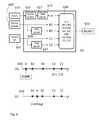
- FIG. 8shows a system for filtering data provided by multiple sensors.
- sensors 805 , 810 and 815are physical sensors that detect acceleration, angular rate, image, sound, position, speed, temperature, vibration, proximity or other physical phenomena.
- the sensorsgenerate a stream of digital data 820 representing sensor measurements.
- analog sensorsmay be combined with analog to digital converters to create digital sensor systems.
- Filters 825 , 830 , 835are integrated circuits and/or processes running on micro processors.
- the filterscombine data from the sensors by applying time delays, logical relationships, amplitude thresholds, Fourier transforms, image recognition, and/or other manipulations.
- the output of the filtersis a stream of events 840 representing information implied by data 820 .
- three sensors and three filtersare shown in FIG. 8 a system may include any number of sensors and any number of filters.
- sensor dataconsists of raw measurements
- eventsinclude judgments about what the measurements signify.
- a value of acceleration, a frequency spectrum of a sound and an average angular rate over a period of one secondare examples of data
- “bump”, “in-pocket” and “not-moving”are examples of events.
- Combining data from multiple physical sensors in a filterreduces the chance that user input to one sensor is inadvertently reported by another sensor, resulting in a misinterpreted gesture. Such a filter thereby increases the utility of an electronic device and improves a user's overall experience with it.
Landscapes
- Engineering & Computer Science (AREA)
- General Engineering & Computer Science (AREA)
- Theoretical Computer Science (AREA)
- Human Computer Interaction (AREA)
- Physics & Mathematics (AREA)
- General Physics & Mathematics (AREA)
- User Interface Of Digital Computer (AREA)
Abstract
Description
Claims (28)
Priority Applications (2)
| Application Number | Priority Date | Filing Date | Title |
|---|---|---|---|
| US12/730,091US8531414B2 (en) | 2010-02-03 | 2010-03-23 | Bump suppression |
| PCT/US2011/029233WO2011119499A2 (en) | 2010-03-23 | 2011-03-21 | Bump suppression |
Applications Claiming Priority (2)
| Application Number | Priority Date | Filing Date | Title |
|---|---|---|---|
| US12/699,692US8577292B2 (en) | 2010-02-03 | 2010-02-03 | Bump validation |
| US12/730,091US8531414B2 (en) | 2010-02-03 | 2010-03-23 | Bump suppression |
Related Parent Applications (1)
| Application Number | Title | Priority Date | Filing Date |
|---|---|---|---|
| US12/699,692Continuation-In-PartUS8577292B2 (en) | 2010-02-03 | 2010-02-03 | Bump validation |
Publications (2)
| Publication Number | Publication Date |
|---|---|
| US20110187652A1 US20110187652A1 (en) | 2011-08-04 |
| US8531414B2true US8531414B2 (en) | 2013-09-10 |
Family
ID=44673819
Family Applications (1)
| Application Number | Title | Priority Date | Filing Date |
|---|---|---|---|
| US12/730,091Active2031-06-24US8531414B2 (en) | 2010-02-03 | 2010-03-23 | Bump suppression |
Country Status (2)
| Country | Link |
|---|---|
| US (1) | US8531414B2 (en) |
| WO (1) | WO2011119499A2 (en) |
Cited By (8)
| Publication number | Priority date | Publication date | Assignee | Title |
|---|---|---|---|---|
| US20140270275A1 (en)* | 2013-03-13 | 2014-09-18 | Cisco Technology, Inc. | Kinetic Event Detection in Microphones |
| US20150067488A1 (en)* | 2012-03-30 | 2015-03-05 | Nokia Corporation | User interfaces, associated apparatus and methods |
| US9015472B1 (en) | 2005-03-10 | 2015-04-21 | Mcafee, Inc. | Marking electronic messages to indicate human origination |
| US20150113068A1 (en)* | 2013-10-18 | 2015-04-23 | Wesley John Boudville | Barcode, sound and collision for a unified user interaction |
| US9160755B2 (en) | 2004-12-21 | 2015-10-13 | Mcafee, Inc. | Trusted communication network |
| US9210111B2 (en) | 2005-02-28 | 2015-12-08 | Mcafee, Inc. | Stopping and remediating outbound messaging abuse |
| US9679072B2 (en) | 2015-01-28 | 2017-06-13 | Wesley John Boudville | Mobile photo sharing via barcode, sound or collision |
| US10354229B2 (en) | 2008-08-04 | 2019-07-16 | Mcafee, Llc | Method and system for centralized contact management |
Families Citing this family (46)
| Publication number | Priority date | Publication date | Assignee | Title |
|---|---|---|---|---|
| CA2742779C (en) | 2008-11-26 | 2017-07-18 | Calgary Scientific Inc. | Method and system for providing remote access to a state of an application program |
| US9992253B2 (en) | 2011-08-15 | 2018-06-05 | Calgary Scientific Inc. | Non-invasive remote access to an application program |
| US8761809B2 (en)* | 2009-11-25 | 2014-06-24 | Visa International Services Association | Transaction using a mobile device with an accelerometer |
| US8510343B2 (en)* | 2010-06-11 | 2013-08-13 | Microsoft Corporation | Cogeneration of database applications and their databases |
| US9965756B2 (en) | 2013-02-26 | 2018-05-08 | Digimarc Corporation | Methods and arrangements for smartphone payments |
| US9741084B2 (en) | 2011-01-04 | 2017-08-22 | Calgary Scientific Inc. | Method and system for providing remote access to data for display on a mobile device |
| CA2823615C (en) | 2011-01-04 | 2017-08-29 | Calgary Scientific, Inc. | A method and system of controlling a remote controlled device in a remote controlled surgical procedure |
| JP5743559B2 (en)* | 2011-01-13 | 2015-07-01 | キヤノン株式会社 | Information processing apparatus, control method and program thereof, and recording medium |
| US9008616B2 (en) | 2011-08-19 | 2015-04-14 | Google Inc. | Point of sale processing initiated by a single tap |
| US9390414B2 (en) | 2011-09-18 | 2016-07-12 | Google Inc. | One-click offline buying |
| WO2013046015A1 (en) | 2011-09-30 | 2013-04-04 | Calgary Scientific Inc. | Uncoupled application extensions including interactive digital surface layer for collaborative remote application sharing and annotating |
| US8868039B2 (en) | 2011-10-12 | 2014-10-21 | Digimarc Corporation | Context-related arrangements |
| KR102027601B1 (en) | 2011-10-18 | 2019-10-01 | 카네기 멜론 유니버시티 | Method and apparatus for classifying touch events on a touch sensitive surface |
| US9785254B2 (en) | 2011-11-01 | 2017-10-10 | Qualcomm Incorporated | System and method for improving orientation data |
| CN104054301B (en) | 2011-11-11 | 2018-05-08 | 卡尔加里科学公司 | Remotely access the session transmission and hang-up in application framework |
| RU2611041C9 (en) | 2011-11-23 | 2017-08-29 | Калгари Сайентифик Инк. | Methods and systems for collaborative application sharing and conferencing |
| TW201328397A (en)* | 2011-12-28 | 2013-07-01 | Ind Tech Res Inst | Method for establishing connection between wireless communication devices |
| US9386434B2 (en) | 2012-01-31 | 2016-07-05 | Nokia Technologies Oy | Method and apparatus for synchronization of devices |
| US9826491B2 (en) | 2012-01-31 | 2017-11-21 | Nokia Technologies Oy | Method and apparatus for synchronization of devices |
| US8774721B2 (en) | 2012-04-10 | 2014-07-08 | Google Inc. | Detecting a communication tap via signal monitoring |
| EP2657827A3 (en)* | 2012-04-26 | 2016-08-03 | Acer Incorporated | Touch detection method and touch control device using the same |
| JP6188288B2 (en)* | 2012-07-20 | 2017-08-30 | キヤノン株式会社 | Information processing apparatus and control method thereof |
| US8970480B2 (en) | 2012-09-14 | 2015-03-03 | Symbol Technologies, Inc. | System and method of device management on extensible and configurable detection of electronic device interactions |
| US20140160085A1 (en)* | 2012-12-07 | 2014-06-12 | Qualcomm Incorporated | Adaptive analog-front-end to optimize touch processing |
| US9026052B2 (en) | 2013-01-24 | 2015-05-05 | Htc Corporation | Mobile electronic device and connection establishment method between mobile electronic devices |
| US9311640B2 (en) | 2014-02-11 | 2016-04-12 | Digimarc Corporation | Methods and arrangements for smartphone payments and transactions |
| US9830588B2 (en) | 2013-02-26 | 2017-11-28 | Digimarc Corporation | Methods and arrangements for smartphone payments |
| US10841289B2 (en) | 2013-03-18 | 2020-11-17 | Digimarc Corporation | Mobile devices as security tokens |
| KR20140114766A (en) | 2013-03-19 | 2014-09-29 | 퀵소 코 | Method and device for sensing touch inputs |
| US9612689B2 (en) | 2015-02-02 | 2017-04-04 | Qeexo, Co. | Method and apparatus for classifying a touch event on a touchscreen as related to one of multiple function generating interaction layers and activating a function in the selected interaction layer |
| US9013452B2 (en) | 2013-03-25 | 2015-04-21 | Qeexo, Co. | Method and system for activating different interactive functions using different types of finger contacts |
| SE537579C2 (en)* | 2013-04-11 | 2015-06-30 | Crunchfish Ab | Portable device utilizes a passive sensor for initiating contactless gesture control |
| DE102013007250A1 (en) | 2013-04-26 | 2014-10-30 | Inodyn Newmedia Gmbh | Procedure for gesture control |
| US9426605B2 (en)* | 2013-10-10 | 2016-08-23 | Yahoo! Inc. | Cross device information exchange using gestures and locations |
| US8928587B1 (en)* | 2013-11-25 | 2015-01-06 | Google Inc. | Automatic device login based on wearable sensor fusion |
| US10007355B2 (en) | 2013-12-18 | 2018-06-26 | Apple Inc. | Gesture-based information exchange between devices in proximity |
| US9329715B2 (en) | 2014-09-11 | 2016-05-03 | Qeexo, Co. | Method and apparatus for differentiating touch screen users based on touch event analysis |
| US11619983B2 (en)* | 2014-09-15 | 2023-04-04 | Qeexo, Co. | Method and apparatus for resolving touch screen ambiguities |
| US10606417B2 (en) | 2014-09-24 | 2020-03-31 | Qeexo, Co. | Method for improving accuracy of touch screen event analysis by use of spatiotemporal touch patterns |
| US10282024B2 (en) | 2014-09-25 | 2019-05-07 | Qeexo, Co. | Classifying contacts or associations with a touch sensitive device |
| US10642404B2 (en) | 2015-08-24 | 2020-05-05 | Qeexo, Co. | Touch sensitive device with multi-sensor stream synchronized data |
| UA115083C2 (en) | 2015-09-08 | 2017-09-11 | Товариство З Обмеженою Відповідальністю "Маіко" | METHOD OF EXCHANGE DATA BETWEEN ELECTRONIC APPLIANCES |
| US11009989B2 (en) | 2018-08-21 | 2021-05-18 | Qeexo, Co. | Recognizing and rejecting unintentional touch events associated with a touch sensitive device |
| US10942603B2 (en) | 2019-05-06 | 2021-03-09 | Qeexo, Co. | Managing activity states of an application processor in relation to touch or hover interactions with a touch sensitive device |
| US11231815B2 (en) | 2019-06-28 | 2022-01-25 | Qeexo, Co. | Detecting object proximity using touch sensitive surface sensing and ultrasonic sensing |
| US11592423B2 (en) | 2020-01-29 | 2023-02-28 | Qeexo, Co. | Adaptive ultrasonic sensing techniques and systems to mitigate interference |
Citations (9)
| Publication number | Priority date | Publication date | Assignee | Title |
|---|---|---|---|---|
| US4972439A (en)* | 1989-01-19 | 1990-11-20 | Motorola, Inc. | Active signalling transmitter control |
| US20060182291A1 (en)* | 2003-09-05 | 2006-08-17 | Nobuyuki Kunieda | Acoustic processing system, acoustic processing device, acoustic processing method, acoustic processing program, and storage medium |
| US20070085157A1 (en)* | 2005-09-30 | 2007-04-19 | Fadell Anthony M | Integrated proximity sensor and light sensor |
| US20080240466A1 (en)* | 2007-03-30 | 2008-10-02 | Remco Martijn Stoutjesdijk | Signal reproduction circuitry |
| US20100033422A1 (en)* | 2008-08-05 | 2010-02-11 | Apple Inc | Systems and methods for processing motion sensor generated data |
| US20100085323A1 (en)* | 2009-12-04 | 2010-04-08 | Adam Bogue | Segmenting a Multi-Touch Input Region by User |
| US20100305899A1 (en)* | 2009-05-29 | 2010-12-02 | Qualcomm Incorporated | Method and apparatus for accurate acquisition of inertial sensor data |
| US20110115784A1 (en)* | 2009-11-17 | 2011-05-19 | Tartz Robert S | System and method of controlling three dimensional virtual objects on a portable computing device |
| US20110126009A1 (en)* | 2009-11-24 | 2011-05-26 | Sony Ericsson Mobile Communications Ab | Event Triggered Pairing of Wireless Communication Devices Based on Time Measurements |
Family Cites Families (4)
| Publication number | Priority date | Publication date | Assignee | Title |
|---|---|---|---|---|
| GB2358108A (en)* | 1999-11-29 | 2001-07-11 | Nokia Mobile Phones Ltd | Controlling a hand-held communication device |
| WO2003001340A2 (en)* | 2001-06-22 | 2003-01-03 | Motion Sense Corporation | Gesture recognition system and method |
| US7797106B2 (en)* | 2005-06-30 | 2010-09-14 | Nokia Corporation | System and method for adjusting step detection based on motion information |
| US7536201B2 (en)* | 2006-03-29 | 2009-05-19 | Sony Ericsson Mobile Communications Ab | Motion sensor character generation for mobile device |
- 2010
- 2010-03-23USUS12/730,091patent/US8531414B2/enactiveActive
- 2011
- 2011-03-21WOPCT/US2011/029233patent/WO2011119499A2/enactiveApplication Filing
Patent Citations (9)
| Publication number | Priority date | Publication date | Assignee | Title |
|---|---|---|---|---|
| US4972439A (en)* | 1989-01-19 | 1990-11-20 | Motorola, Inc. | Active signalling transmitter control |
| US20060182291A1 (en)* | 2003-09-05 | 2006-08-17 | Nobuyuki Kunieda | Acoustic processing system, acoustic processing device, acoustic processing method, acoustic processing program, and storage medium |
| US20070085157A1 (en)* | 2005-09-30 | 2007-04-19 | Fadell Anthony M | Integrated proximity sensor and light sensor |
| US20080240466A1 (en)* | 2007-03-30 | 2008-10-02 | Remco Martijn Stoutjesdijk | Signal reproduction circuitry |
| US20100033422A1 (en)* | 2008-08-05 | 2010-02-11 | Apple Inc | Systems and methods for processing motion sensor generated data |
| US20100305899A1 (en)* | 2009-05-29 | 2010-12-02 | Qualcomm Incorporated | Method and apparatus for accurate acquisition of inertial sensor data |
| US20110115784A1 (en)* | 2009-11-17 | 2011-05-19 | Tartz Robert S | System and method of controlling three dimensional virtual objects on a portable computing device |
| US20110126009A1 (en)* | 2009-11-24 | 2011-05-26 | Sony Ericsson Mobile Communications Ab | Event Triggered Pairing of Wireless Communication Devices Based on Time Measurements |
| US20100085323A1 (en)* | 2009-12-04 | 2010-04-08 | Adam Bogue | Segmenting a Multi-Touch Input Region by User |
Non-Patent Citations (1)
| Title |
|---|
| International Search Report and Written Opinion of the International Searching Authority in PCT/US2011/0292233, Oct. 26, 2011. |
Cited By (14)
| Publication number | Priority date | Publication date | Assignee | Title |
|---|---|---|---|---|
| US9160755B2 (en) | 2004-12-21 | 2015-10-13 | Mcafee, Inc. | Trusted communication network |
| US10212188B2 (en) | 2004-12-21 | 2019-02-19 | Mcafee, Llc | Trusted communication network |
| US9210111B2 (en) | 2005-02-28 | 2015-12-08 | Mcafee, Inc. | Stopping and remediating outbound messaging abuse |
| US9560064B2 (en) | 2005-02-28 | 2017-01-31 | Mcafee, Inc. | Stopping and remediating outbound messaging abuse |
| US9015472B1 (en) | 2005-03-10 | 2015-04-21 | Mcafee, Inc. | Marking electronic messages to indicate human origination |
| US9369415B2 (en) | 2005-03-10 | 2016-06-14 | Mcafee, Inc. | Marking electronic messages to indicate human origination |
| US10354229B2 (en) | 2008-08-04 | 2019-07-16 | Mcafee, Llc | Method and system for centralized contact management |
| US11263591B2 (en) | 2008-08-04 | 2022-03-01 | Mcafee, Llc | Method and system for centralized contact management |
| US20150067488A1 (en)* | 2012-03-30 | 2015-03-05 | Nokia Corporation | User interfaces, associated apparatus and methods |
| US9841893B2 (en)* | 2012-03-30 | 2017-12-12 | Nokia Technologies Oy | Detection of a jolt during character entry |
| US20140270275A1 (en)* | 2013-03-13 | 2014-09-18 | Cisco Technology, Inc. | Kinetic Event Detection in Microphones |
| US9560444B2 (en)* | 2013-03-13 | 2017-01-31 | Cisco Technology, Inc. | Kinetic event detection in microphones |
| US20150113068A1 (en)* | 2013-10-18 | 2015-04-23 | Wesley John Boudville | Barcode, sound and collision for a unified user interaction |
| US9679072B2 (en) | 2015-01-28 | 2017-06-13 | Wesley John Boudville | Mobile photo sharing via barcode, sound or collision |
Also Published As
| Publication number | Publication date |
|---|---|
| WO2011119499A3 (en) | 2011-12-22 |
| US20110187652A1 (en) | 2011-08-04 |
| WO2011119499A2 (en) | 2011-09-29 |
Similar Documents
| Publication | Publication Date | Title |
|---|---|---|
| US8531414B2 (en) | Bump suppression | |
| CN109513210B (en) | Virtual vehicle drifting method and device in virtual world and storage medium | |
| EP3114556B1 (en) | Proximity sensor-based interactions | |
| US9400489B2 (en) | Smart watch and control method thereof | |
| KR101543143B1 (en) | Motion-based device operations | |
| KR101477442B1 (en) | Methods and apparatuses for gesture-based user input detection in a mobile device | |
| EP3732871B1 (en) | Detecting patterns and behavior to prevent a mobile terminal drop event | |
| US20190253619A1 (en) | Media capture lock affordance for graphical user interface | |
| CN109324739B (en) | Virtual object control method, device, terminal and storage medium | |
| KR20150033902A (en) | Smart watch and method for controlling thereof | |
| WO2011163350A1 (en) | Switching between a first operational mode and a second operational mode using a natural motion gesture | |
| KR20140079012A (en) | Mobile apparatus having function of face recognition with additional component | |
| EP3183625B1 (en) | Modal body touch using ultrasound | |
| CN110100154B (en) | Apparatus, method and graphical user interface for launching an application | |
| CN109117619B (en) | Fingerprint unlocking method and related product | |
| US9983693B2 (en) | Spatial motion-based user interactivity | |
| CN108287655A (en) | A kind of interface display method, interface display apparatus and mobile terminal | |
| CN110072010B (en) | Drop detection method and terminal equipment | |
| CN107466387A (en) | A kind of method and device for detecting touch manner | |
| KR20140103043A (en) | Electronic device, method and computer readable recording medium for operating the electronic device | |
| CN107943406A (en) | A kind of touch-screen touch point determines method and terminal | |
| US20160202788A1 (en) | Multi-on-body action detection based on ultrasound | |
| US10558270B2 (en) | Method for determining non-contact gesture and device for the same | |
| US20160282949A1 (en) | Method and system for detecting linear swipe gesture using accelerometer | |
| CN113879925B (en) | Elevator control method, device, equipment and storage medium |
Legal Events
| Date | Code | Title | Description |
|---|---|---|---|
| AS | Assignment | Owner name:BUMP TECHNOLOGIES, INC., CALIFORNIA Free format text:ASSIGNMENT OF ASSIGNORS INTEREST;ASSIGNOR:HUIBERS, ANDREW G;REEL/FRAME:026219/0593 Effective date:20110421 | |
| STCF | Information on status: patent grant | Free format text:PATENTED CASE | |
| AS | Assignment | Owner name:GOOGLE INC., CALIFORNIA Free format text:ASSIGNMENT OF ASSIGNORS INTEREST;ASSIGNOR:BUMP TECHNOLOGIES, INC.;REEL/FRAME:031405/0919 Effective date:20130913 | |
| FEPP | Fee payment procedure | Free format text:PAT HOLDER NO LONGER CLAIMS SMALL ENTITY STATUS, ENTITY STATUS SET TO UNDISCOUNTED (ORIGINAL EVENT CODE: STOL); ENTITY STATUS OF PATENT OWNER: LARGE ENTITY | |
| FPAY | Fee payment | Year of fee payment:4 | |
| AS | Assignment | Owner name:GOOGLE LLC, CALIFORNIA Free format text:CHANGE OF NAME;ASSIGNOR:GOOGLE INC.;REEL/FRAME:044101/0299 Effective date:20170929 | |
| MAFP | Maintenance fee payment | Free format text:PAYMENT OF MAINTENANCE FEE, 8TH YEAR, LARGE ENTITY (ORIGINAL EVENT CODE: M1552); ENTITY STATUS OF PATENT OWNER: LARGE ENTITY Year of fee payment:8 | |
| MAFP | Maintenance fee payment | Free format text:PAYMENT OF MAINTENANCE FEE, 12TH YEAR, LARGE ENTITY (ORIGINAL EVENT CODE: M1553); ENTITY STATUS OF PATENT OWNER: LARGE ENTITY Year of fee payment:12 |