US8531394B2 - Unitized, vision-controlled, wireless eyeglasses transceiver - Google Patents
Unitized, vision-controlled, wireless eyeglasses transceiverDownload PDFInfo
- Publication number
- US8531394B2 US8531394B2US13/034,182US201113034182AUS8531394B2US 8531394 B2US8531394 B2US 8531394B2US 201113034182 AUS201113034182 AUS 201113034182AUS 8531394 B2US8531394 B2US 8531394B2
- Authority
- US
- United States
- Prior art keywords
- user
- eye
- video
- image
- processor
- Prior art date
- Legal status (The legal status is an assumption and is not a legal conclusion. Google has not performed a legal analysis and makes no representation as to the accuracy of the status listed.)
- Active, expires
Links
Images


Classifications
- G—PHYSICS
- G06—COMPUTING OR CALCULATING; COUNTING
- G06F—ELECTRIC DIGITAL DATA PROCESSING
- G06F3/00—Input arrangements for transferring data to be processed into a form capable of being handled by the computer; Output arrangements for transferring data from processing unit to output unit, e.g. interface arrangements
- G06F3/01—Input arrangements or combined input and output arrangements for interaction between user and computer
- G06F3/011—Arrangements for interaction with the human body, e.g. for user immersion in virtual reality
- G06F3/013—Eye tracking input arrangements
- G—PHYSICS
- G02—OPTICS
- G02B—OPTICAL ELEMENTS, SYSTEMS OR APPARATUS
- G02B27/00—Optical systems or apparatus not provided for by any of the groups G02B1/00 - G02B26/00, G02B30/00
- G02B27/0093—Optical systems or apparatus not provided for by any of the groups G02B1/00 - G02B26/00, G02B30/00 with means for monitoring data relating to the user, e.g. head-tracking, eye-tracking
- G—PHYSICS
- G02—OPTICS
- G02B—OPTICAL ELEMENTS, SYSTEMS OR APPARATUS
- G02B27/00—Optical systems or apparatus not provided for by any of the groups G02B1/00 - G02B26/00, G02B30/00
- G02B27/01—Head-up displays
- G02B27/017—Head mounted
- G—PHYSICS
- G02—OPTICS
- G02B—OPTICAL ELEMENTS, SYSTEMS OR APPARATUS
- G02B7/00—Mountings, adjusting means, or light-tight connections, for optical elements
- G02B7/28—Systems for automatic generation of focusing signals
- G02B7/287—Systems for automatic generation of focusing signals including a sight line detecting device
- G—PHYSICS
- G02—OPTICS
- G02B—OPTICAL ELEMENTS, SYSTEMS OR APPARATUS
- G02B27/00—Optical systems or apparatus not provided for by any of the groups G02B1/00 - G02B26/00, G02B30/00
- G02B27/01—Head-up displays
- G02B27/0101—Head-up displays characterised by optical features
- G02B2027/0138—Head-up displays characterised by optical features comprising image capture systems, e.g. camera
- G—PHYSICS
- G02—OPTICS
- G02B—OPTICAL ELEMENTS, SYSTEMS OR APPARATUS
- G02B27/00—Optical systems or apparatus not provided for by any of the groups G02B1/00 - G02B26/00, G02B30/00
- G02B27/01—Head-up displays
- G02B27/0101—Head-up displays characterised by optical features
- G02B2027/014—Head-up displays characterised by optical features comprising information/image processing systems
- G—PHYSICS
- G02—OPTICS
- G02B—OPTICAL ELEMENTS, SYSTEMS OR APPARATUS
- G02B27/00—Optical systems or apparatus not provided for by any of the groups G02B1/00 - G02B26/00, G02B30/00
- G02B27/01—Head-up displays
- G02B27/017—Head mounted
- G02B2027/0178—Eyeglass type
- G—PHYSICS
- G02—OPTICS
- G02B—OPTICAL ELEMENTS, SYSTEMS OR APPARATUS
- G02B27/00—Optical systems or apparatus not provided for by any of the groups G02B1/00 - G02B26/00, G02B30/00
- G02B27/01—Head-up displays
- G02B27/0179—Display position adjusting means not related to the information to be displayed
- G02B2027/0187—Display position adjusting means not related to the information to be displayed slaved to motion of at least a part of the body of the user, e.g. head, eye
Definitions
- the inventionrelates to the fields of eye tracking devices and optical user interfaces, particularly as applied to the control of wireless communications.
- Prior art devicesutilize optical correction lenses and mirrors that optically correct the display so as to create the appearance of a virtual image of the display that appears to be originating from a much further distance.
- Beam splittersoften semi-silvered mirrors or other optical glass, often located at a 45 degree angle between the user's eyes and various distant objects, can then allow the user to simultaneously see both a virtual image of the display in proper focus, as well as images of other distant objects.
- prior art head-mounted framese.g., eyeglasses frames
- beam splittersto create a virtual image viewable by the user
- This traditional configurationis so conspicuous and bulky as to give the user an artificial human “Cyborg” like appearance.
- this prior art configurationis unsuitable.
- wireless communications systemthat allows for inconspicuous communications by the user while allowing for eye control of such communications. More particularly, improved communications devices and methods are needed that enable the user to discretely or inconspicuously receive and respond to at least short incoming text messages in a way that is both consistent with the distant parties desire and expectation of instant communications, and is also consistent with the other local parties expectation of undivided attention.
- wireless communications systemwhich includes an image/video capturing system for capturing and transmitting still images or motion video (previously recorded or real-time) using eye control techniques.
- the inventionprovides a device and method for allowing a user to inconspicuously send and receive messages and other information, often short text communications.
- the present inventionminimizes any outward appearance that the user is engaging in the process of receiving and transmitting wireless messages and is visually inconspicuous, since an unusual looking piece of equipment will itself attract unwanted attention.
- the inventionhas an outward appearance resembling standard eyeglasses or sun glasses, has a built in wireless transceiver, and the device enables a user to discretely view incoming wireless text messages using an optical display built into the eyeglass frame.
- the inventionalso allows the user to discretely transmit outgoing text messages by a process in which the user simply moves his or her eyes and gazes in various defined directions.
- the device's eye tracking systems and artificial vision or video interpretation softwarecan track the motion or gaze of the user's eyes, and convert this motion and gaze into message symbols and commands. The device then transmits the resulting message.
- the inventionis self-contained and operates, when placed on the user's head, without the need of external battery packs or external transceivers.
- the inventionincludes one or more outwardly-facing image/video capturing devices and associated subsystems which enable the user to capture and transmit still pictures and/or motion video, using eye control techniques.
- the captured images and/or videocan be inserted into a text message and/or and e-mail message and transmitted to a desired recipient.
- Live videocan also be captured and transmitted to a recipient in real-time.
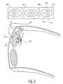
- FIG. 1shows an overview of the device
- FIG. 2shows an embodiment of the device's beam splitter optical display
- FIG. 3shows an embodiment of the device's eye tracking system
- FIG. 4shows the device communicating with a cellular phone base station
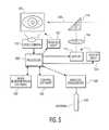
- FIG. 5shows the electrical circuitry of the device
- FIG. 6shows an example of a user interface for the device
- FIGS. 7A-7Bare flowcharts showing processing steps capable of being carried out by the control software of the device.
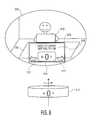
- FIG. 8shows an overview of the front of another embodiment of the present invention, which includes at least one outwardly facing camera for capturing and transmitting still images and/or motion video in the visual and/or non-visual spectra, using eye control techniques;
- FIG. 9is a diagram showing hardware and software components of the device shown in FIG. 8 ;
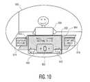
- FIG. 10shows an example of a user interface for controlling the device of FIG. 8 ;
- FIG. 11is a flowchart showing processing steps capable of being carried out by the control software of the embodiment shown in FIG. 8 .
- the inventionmay be a unitized or self-contained, head-mounted, combination eye-tracking and display device for transmitting and receiving information.
- This devicemay generally comprise a head-mountable frame, such as an eyeglasses frame, configured to hold one or more lenses (such as two eyeglasses lenses) in front of the user's eye or eyes.
- the devicemay also comprise at least one user eye-tracking sensor, such as a miniature video camera, positioned to track movement of one or both eyes of the user.
- the at least one eye-tracking sensorcould be mounted on the head-mountable frame.
- the devicemay also comprise at least one processor, such as a microprocessor or digital signal processor, programmed to execute eye tracking executable code and control other communications and interface executable code as well.
- the devicemay also comprise at least one optical system mounted or configured to render a virtual image of a visual display viewable by the device's user.
- This optical systemmay be spatially positioned in the space within or between a boundary defined by a lens, such as one of the two eyeglasses lenses, positioned in front of the eye of the user, and the eye of the user.
- the devicemay also comprise at least one wireless transceiver positioned in close proximity to the head-mounted frame (and which could be attached to or integrated into the frame).
- This wireless transceivermay be configured to receive wireless information from outside sources, and to transmit this wireless information (e.g. text messages, email) to the visual display.
- the devicemay also comprise at least one processor programmed to execute eye tracking code (software) and other executable control code.
- eye tracking codesoftware
- This eye tracking codecan, in the case where the eye-tracking sensor is a miniature video camera, comprise artificial vision software to interpret the images obtained by the camera, and extract eye gaze direction information. This eye gaze direction information can then be analyzed and used to control the device by other software algorithms and executable code.
- the executable control codehas multiple functions. It controls the user display and interface, and also takes commands from the eye tracking code and in turn command the device to transmit wireless information.
- the eye tracking sensortracks the motion of the user's eyes, and translates the motion of the user's eye into at least one symbol or command.
- the deviceis configured to then transmit this at least one symbol or command using the device's wireless transceiver, and the device may also display received symbols for the user to view using the device's optical system.
- the inventionmay be a self-contained head-mounted combination eye-tracking and display device for sending and receiving wireless information by a user.
- the inventionmay comprise a head-mounted frame, such as an eyeglasses frame, configured to hold lenses in front of the user's eyes, and may have at least one user eye-tracking sensor mounted on this frame.
- the eye tracking sensormay often comprise one or more infrared light sources and one or more video camera(s) or sensor(s) configured to detect near infrared light.
- These near-infrared light source(s)may be configured to shine near infrared into the user's eye or eyes, thus illuminating the user's eye or eyes.
- the video camera(s)in turn may be configured to focus onto these near-infrared illuminated eyes.
- the devicemay also comprise at least one processor (such as a microprocessor), eye tracking software and control software, as well as at least one visual display and an optical system mounted on the head-mounted frame.
- the optical systemincludes a beam splitter and a converging lens or converging mirror, and is configured to produce a virtual image of the visual display that is viewable by a user of the device.
- the optical systemmay be configured to not spatially extend beyond the eyeglasses lenses in front of the user's eyes.
- the visual displaymay display data such as at least one visual target for a symbol intended for wireless transmission when the user's eyes are directed at this target.
- the devicemay also comprise at least one wireless transceiver mounted on this head-mounted frame.
- the devicemay also be configured so that the wireless transceiver may receive wireless information, and send this wireless information to the visual display.
- the devicemay also be configured so that the at least one processor, eye tracking software, and other control software can direct the device to transmit wireless information by tracking the motion of the user's eyes using the eye tracking sensor or sensors.
- the device's processor(s) and softwaremay be configured to translate the gaze or motion of the user's eyes into at least one symbol or command, and then transmit this at least one symbol or command using the device's wireless transceiver.
- the eyeglass lensesmay or may not have optical correction capability. That is, the eyeglass lenses may be customized for the particular optical correction needs for an individual user, or alternatively may be of a standard non-customized type configured either for a user with good uncorrected vision, or a user who has his or her vision corrected by other means, such as contact lenses.
- the devicemay often be used at night, in dimly lit restaurants, and under other low light conditions where there may be insufficient ambient light for the device's eye tracking sensor (often a miniature video camera) to get a good image of the user's eye.
- the eye tracking sensormay include at least one near infrared light source configured to illuminate the same user eye or eyes that are also being monitored by the device's video camera(s).
- visible light sourcesmay also be used.
- LEDLight Emitting Diodes
- Infrared light sourcesparticularly near-infrared light sources (e.g., light sources between about 700 nm and 1200 nm or longer wavelengths) are preferable simply because, if visible light sources are used to illuminate the user's eye in a low ambient light environment, the user's visibly lit eye or eyes will also be apparent to other individuals in the vicinity, thus defeating one purpose of the invention, which is to allow the user to communicate inconspicuously.
- the video camera focused on the user's eyeis preferably capable of operating with good sensitivity in infrared wavelengths.
- Standard light detecting sensorssuch as charged coupled devices (CCD), are notably quite capable of working in the near infrared region, and may be used for this purpose.
- CCDcharged coupled devices
- One type of optical systemmay comprise a miniature display device, which may be built into the stem of the eyeglass frame, such as on the inside near the eyeglass lens, along with a converging lens or mirror, and a beam splitter which may, in some embodiments, be mounted on the interior (user's eye side) of at least one eyeglass lens.
- a beam splitter or prismmay be mounted on the inside of the eyeglass lens in a manner roughly similar to that of the position of the bifocal correcting portion of a bifocal lens.
- an optical correction devicesuch as a converging lens, may be mounted either on or near the miniature display device, or on or near the beam splitter, or in between.
- This optical correction devicecan take the image generated by the miniature display device, and display the image as if the image was coming from a longer distance away, thus allowing the user's eyes, while focused on more distant objects in the outside environment, to see the image generated by the display floating superimposed with the outside objects and in sharp focus.
- the beam splitter arrangementmay be further concealed by configuring the eyeglasses to resemble standard sunglasses, and by making the lenses from optically dark or reflecting material. Thus, the beam splitter arrangement will be hidden, and the user, who is apparently only wearing sunglasses, may thus communicate without attracting attention from outside persons.
- LCDLiquid Crystal Displays
- OLEDOrganic light emitting diode displays
- Electronic paper displaysA variety of different display technologies may be used for the display device. These display technologies include, but are not limited to, Liquid Crystal Displays (LCD), Organic light emitting diode displays (OLED), and Electronic paper displays.
- LCDLiquid Crystal Displays
- OLEDOrganic light emitting diode displays
- Electronic paper displaysA variety of different display technologies may be used for the display device.
- the optical displaymay also show one or more targets for the user to gaze upon.
- targetsmay include control targets, as well as targets for symbols, such as numbers or letters of the alphabet, that the user may wish to gaze upon in order to create messages to transmit.
- the devicemay contain one or more wireless transceivers, configured to transmit and receive either short range wireless (e.g., with a typical range under 300 feet) or longer range wireless (such as cellular telephone wireless), often capable of being transmitted over longer distances of at least several miles or more.
- short range wireless protocolsinclude the various IEEE 802.15 protocols such as BlueToothTM, ZigbeeTM protocols, as well as other protocols such as the various IEEE 802.11 WiFi protocols.
- suitable longer range wireless protocolsinclude cellular telephone 0G, 1G, 2G, 3G, 4G, protocols, GSM, GPRS, CDMA, EV-DO, DECT, IS-136/TDMA, iDEN, GSM EDGE standards, 2-way-wireless-messaging FM transmissions, and other wireless communications modalities that transmit signals beyond a radius of approximately 300 feet.
- the devicecould include at least one battery to power the various components.
- This batterymay be a single use battery, but could also be a rechargeable battery. If a rechargeable battery is used, often the device will be sold with a battery recharging device, such as a recharging stand that can in turn plug into a standard AC wall socket, and recharge the battery.
- a battery recharging devicesuch as a recharging stand that can in turn plug into a standard AC wall socket, and recharge the battery.
- Alternative power sourcessuch as frame mounted solar cells to recharge the battery, plug in automobile chargers, etc. may also be used.
- the systemcould include one or more outwardly facing image/video capturing devices and associated subsystems which enable the user to capture and transmit still pictures and/or video images, using eye control techniques.
- the captured images and/or videocan be inserted into a text message and/or and e-mail message and transmitted to a desired recipient. Live video can also be captured and transmitted to a recipient.
- FIG. 1shows an overview of the device 100 , showing the head-mounted or mountable frame (here, an eyeglass frame) 102 .
- This head-mounted or mountable frame 102is often divided into a frame front 104 and two frame temples 106 that extend over or behind the ears to hold the head-mounted frame in place.
- the framewill often have one or usually two lenses, such as eyeglass lenses or sunglasses lenses 108 and 110 .
- the devicewill often have an optical system, that may consist of a display 112 , a display lens or mirror such as a converging lens or mirror 114 , and a beam splitter 116 which may either be mounted on the eyeglass lens 108 or may be held separately.
- an optical systemthat may consist of a display 112 , a display lens or mirror such as a converging lens or mirror 114 , and a beam splitter 116 which may either be mounted on the eyeglass lens 108 or may be held separately.
- the device's eye tracking sensorwhich in this embodiment is one or more miniaturized video camera(s), is shown as 118 .
- One or more eye illumination lightssuch as near infrared lights, configured to shine near infrared light onto at least one of the user's eyes 120 is shown as 122 .
- FIG. 2shows one example of how the visual display may work.
- the display 112which may be located in the inner portion of the frame temple 106 near the frame front 104 , may display a message—for example a brief text message from the user's next appointment such as “Need to change meeting to 4:00 PM” The display 112 will show this message. Depending upon the type of display used and environmental conditions, the display may be back lit or illuminated (not shown) to provide better contrast.
- the displaywill often be located too close to the user's eye 120 for the eye to focus on properly.
- the displaymay be imaged by a mirror or lens, such as a converging lens 114 , to correct the light rays 200 so that they appear to be coming from a more distant virtual object.
- the light raysthen may pass through the beam splitter 116 , and into the user's eye 120 .
- the userwill see the image of the display and the message as if the display and message were floating in the air 202 in front of the user.
- the userwill also be able to see distant objects through the eyeglasses lenses as well.
- this optical systemmay be replicated on the other side of the frame as well, thus allowing both of the user's eyes to see the message.
- This dual optical system embodimentalthough more expensive to produce, will likely be appreciated by users who wish a more premium experience.
- FIG. 3shows one example of how the eye tracking sensor may track the motion of the user's eye 120 .
- the user's eye 120is illuminated by near infrared light from one or more frame mounted infrared lights 122 .
- the frame mounted video camera 118which is focused on the user's eye 120 , captures images of the eye 120 as the eye gazes in different directions, and looks at different virtual targets presented by the visual display system. Some of the images captured by video camera 118 as the eye 120 looks in different directions shown as 300 , 302 , and 304 . In direction 300 , the eye is looking to the left, in direction 302 , the eye is looking straight ahead, and in direction 304 , the eye is looking to the right.
- the eye tracking sensorwill be mounted or coupled directly to the frame. In other embodiments, the eye tracking sensor will not be integrally mounted or coupled to the frame, but may rather be attached and detached from the frame, and thus in these embodiments, the eye tracking sensor system is said to be couplable to the frame.
- this eye tracking sensormay be replicated on the other side of the frame as well, thus allowing both of the user's eyes to be tracked. Again, this dual eye tracking embodiment, although more expensive to produce, will again likely be appreciated by users who wish a more premium experience, and it is likely that tracking both of the user's eyes will also improve the accuracy of the eye gaze tracking system.
- the video camera 118can look at a number of different visual elements of the eye. These elements include the relative shape and location of the pupil 310 , the iris 312 , and sclera 314 of the eye, along with assorted blood vessels 316 , and other distinguishing marks on the sclera. In addition to these features, motion of other eye structures, such as the eyelids, blinking rates and patterns, squinting, etc. may also be monitored.
- FIG. 4shows the device wirelessly communicating with a cellular phone base station.
- a wireless transceiver onboard the devicefor example, a miniaturized transceiver circuit, antenna, and battery that may be embedded in the temple portion of the device's frame 106
- a wireless incoming messagefrom a cellular phone tower 400 by way of a standard cellular phone wireless protocol, such as the previously discussed 0G, 1G, 2G, 3G or 4G protocol, GSM, GPRS, CDMA, EV-DO, EDGE, DECT, IS-136/TDMA, iDEN or other protocol 402 .
- a standard cellular phone wireless protocolsuch as the previously discussed 0G, 1G, 2G, 3G or 4G protocol, GSM, GPRS, CDMA, EV-DO, EDGE, DECT, IS-136/TDMA, iDEN or other protocol 402 .
- This incoming messageis processed by an onboard processor (e.g., microprocessor) and software, and is output on display 112 , in this example as the received text message “Need to change meeting to 4:00 PM”
- the userwill use the optical system to sec a virtual image of this text message appearing as if floating in the air in front of them, as indicated by 404 .
- the userwho may, for example, be at a restaurant talking to another client, can unobtrusively receive this text message, and then by various eye motions, which will be detected by video camera 118 , processed by the device's processor and eye tracking software, and converted into a return message along with a transmit command.
- the transmitted message 406may be “OK”
- This messagewill be wirelessly transmitted (i.e., using protocol 402 ) back to the cellular telephone base station 400 or other network, and from there to the client on the other end of the text message conversation.
- FIG. 5shows a detail of some of the electrical and optical circuitry that may be used in the device.
- the devicemay be controlled by one or more processors 500 , which may be microprocessors, possibly assisted, supplemented, or supplanted by one or more digital signal processors (DSP).
- the processor(s)in turn executes code or software, such as general control software 502 and image interpretation software 504 intended to analyze images of the eye returned from video camera 118 , and determine from these images information pertaining to the direction of eye gaze, as well as various control signals, which may be conveyed by squinting, blinking, unusual eye movement and the like that may be useful for controlling the device.
- code or softwaresuch as general control software 502 and image interpretation software 504 intended to analyze images of the eye returned from video camera 118 , and determine from these images information pertaining to the direction of eye gaze, as well as various control signals, which may be conveyed by squinting, blinking, unusual eye movement and the like that may be useful for controlling the device.
- the processor(s) 500may operate one or more wireless transceivers 506 , which in turn may be connected to an antenna 508 , which may be incorporated or embedded into the head-mounted frame, such as the eyeglasses frame.
- the processorwill also send data to a display 112 for viewing by the user through optical system lens components 114 and beam splitter components 116 .
- the processormay optionally control a display illumination light 510 to improve display visibility as needed.
- the eye tracking softwaremay be implemented using a variety of different types of image interpretation software. Some of these methods include the methods of Oyewole Oyekoya, “ Eye Tracking, A Perceptual Interface for Content Based Image Retrieval ”, Ph.D. Thesis 2007, Department of Electronic & Electrical Engineering, Adastral Park Campus, University Park London. Alternative methods include the methods of Selker et. al., “ Eye - R, a glasses mounted - eye motion detection interface ”, Conference on Human Factors in Computing Systems, CHI '01 extended abstracts on Human factors in computing systems, pages 179-180, and other methods.
- the human eyehas a number of structures, such as the pupil, iris, and sclera which artificial vision software can use to track the eye, and determine where the eye is pointing or gazing at any given moment of time.
- using the gaze of the eye to control devicesis complicated by the fact that the position of the eye is constantly shifting.
- the human eyedoes not gaze at objects of interest in a steady uniform manner, but rather, scans objects of interest by a series of saccades or rapid eye movements.
- the human eyeacts much like a cross between a camera and a scanner, and indeed, this scanning motion helps make up for the inherent deficiencies and limitations of the eye in terms of its performance as a natural camera.
- the eye tracking software and processormust take this natural constant saccade movement into account.
- Other workers in the fieldsuch as Oyekoya, have shown that when such constant movement is compensated for, eye gaze can be an effective way to understand user intentions, and in fact in some situations eye gaze can even select objects of interest faster than alternative user interfaces, such as computer mice.
- the automated interpretation of human eye gazingis facilitated if the automated interpretation system knows the location of the objects of interest or targets that the eye is likely to be gazing upon. The automated system can then use its knowledge about the location of these targets, often called salient images, to help interpret the series of eye movements as detected by the artificial vision software.
- this target informationis known because the invention is displaying these targets in specific locations in the invention's display 112 .
- the eye tracking softwaremay operate by first storing in memory the location of various visual display targets, such as symbol targets and control targets that the system is displaying on display 112 .
- the softwaremay then process eye movement data and attempt to determine which target the eye is gazing on by, for example. making use of algorithms such as the Oyekoya eye gaze interpretation software algorithms. These algorithms include steps such as determining if the eye is revisiting on particular target regions, and determining if the eye has a tendency to visit the target region just prior to the main incidence of target fixation.
- the speed of the eye saccademay also be used to give relevant information, because saccade speeds tend to slow down right before the target image of interest is selected.
- Other methodsinclude determining changes in eye pupil diameter, because pupil diameter can tend to change when the eye is gazing upon an intended target region. Dwell time on the target may also be used because this also gives important information that the eye is fixing on a particular target.
- the eye tracking softwarewill often also use various statistical methods, such as Analysis of Variance (ANOVA) to analyze the eye tracking data, as well as to calibrate itself to the individual characteristics of any given user.
- ANOVAAnalysis of Variance
- GaZIRGaze-based Zooming Interface for Image Retrieval
- ICMI-MLMI 2009, 2-6 Nov. 2009, Cambridge, Mass., USAor other method.
- the GaZIR interfaceutilizes a gaze based zooming interface to allow the user to progressively zoom in on targets of interest by continuing to gaze at them.
- the interfacecontrols the speed of appearance of new letters based upon information determined by the user's gaze.
- FIG. 6One embodiment of the invention's visual interface is shown in FIG. 6 .
- the useris wearing the device, and the overall view 600 shows the user's view, as if peering out through glasses.
- the useris sitting at desk or restaurant table 602 across from another person 604 , and the view of the other person and other outside world objects in the upper part of the scene is unobstructed.
- the usersees both a view of the outside world, and a view 606 of the display 112 as conveyed to the user's eye by way of correcting lens 114 and beam splitter 116 .
- the beam splitteris again placed in the lower portion of the field of view, in a manner similar to a bifocal lens arrangement.
- the usersees a view of an incoming message, such as a text message 608 , which has been received by the device's transceiver.
- a gaze based interfaceto select the letter “O” to form the desired “OK” response to transmit.
- various symbols (e.g., letters) 610 intended for transmissionzoom in and out of view as if the letters were rotating on the surface of a virtual wheel 612 spinning perpendicular to the user.
- this “virtual wheel”is a software construct, generated by executable code, and the use of the “virtual wheel” model is intended to convey in simple terms some of the various functions that the device's display software may employ in the process of generating the visual user interface.
- various control symbolsfor example symbols for “space,” “backspace,” “capital letters,” “send,” “receive”, “next message,” “previous message” and the like may also be put on the surface of the virtual wheel 612 and displayed to the user.
- simple phrasessuch as “OK,” “Yes,” “No,” “Busy,” “Get back to you soon,” and so on, along with various user determined pre-coded messages, may also be encoded as particular symbols. Indeed, such phrases may be pre-encoded along with the appropriate commands to reply to an incoming message and transmit, so that a user need simply glance at the symbol for OK for a sufficient time, and the system will know to then respond to any incoming text message with this response.
- the devicemay also be programmed append additional explanatory text, such as “sent from an eye-gaze commanded device” or the manufacturer's proprietary name for the device, so that the recipient of the return message will not be put off or offended by the occasionally brief or terse nature of the response.
- additional explanatory textsuch as “sent from an eye-gaze commanded device” or the manufacturer's proprietary name for the device, so that the recipient of the return message will not be put off or offended by the occasionally brief or terse nature of the response.
- the usermay select which letters, numbers, or control symbols to use by gazing at a left rotate 612 and right rotate 614 control target, which may control the order in which the letters are displayed by, for example, rotating the virtual wheel 612 in the selected direction.
- the usercan then select the desired letters numbers, or control symbols by gazing at the displayed letters, numbers, or control symbols for a sufficient amount of time to let the system know that this letter number, or control symbol is desired.
- the virtual wheel 612 used to determine the order in which letters, symbols and control elements or symbols are displayedcan be a virtual sphere, and the user can rotate this sphere around more than one axis by appropriate gazing at control targets.
- more than one type of virtual wheel 612may be used, for example one for the alphabet, one for predetermined messages, one for numbers, one for control commands, one to speed dial frequent contacts, to further enhance the speed and flexibility of the interface.
- FIGS. 7A-7Bare flowcharts showing processing steps capable of being carried out by the control software 502 of the device.
- the control software 502could be coded in any suitable high- or low-level programming language (e.g., C, C++, Java, etc.), and could be embodied as computer-readable instructions stored in non-volatile memory.
- the steps discussed in connection with FIGS. 7A-7Bare illustrative in nature, and it is conceivable that other control approaches could be developed and are considered within the scope and spirit of the present invention.
- the process steps shown in FIG. 7Apermit a user of the device to view an incoming message (e.g., a text message, e-mail, etc.), and to construct and transmit a reply using the device.
- an incoming messageis received by the device (e.g., wirelessly, using the wireless transceiver 506 and the antenna 508 of FIG. 5 ).
- the processor 500displays a user interface screen which includes the received message on the display 112 .
- the processor 500aligns grid values with screen elements forming part of the user interface screen.
- Block 707permits the user to construct a message (e.g., a reply message) using the display 112 .
- step 708the processor continuously monitors the user's eye position using images of the user's eye acquired by the video camera 118 and the image interpretation software 504 , for the purpose of allowing a user to construct a reply message.
- the reply messagecould be constructed using the virtual wheel discussed above, a virtual keyboard, or any other suitable interface.
- the processor 500determines grid coordinates which correspond to the user's pupil, in order to determine where the user's eye is looking on the screen.
- step 710the processor 500 determines whether the user wishes to advance one letter, symbol, or number. Thus, for example, if the user interface screen is displaying the virtual wheel discussed above, the processor 500 can determine if the user is looking at a screen element for advancing the wheel one letter. If so, step 712 occurs, wherein the processor 500 advances the virtual wheel one letter, symbol, or number, and updates the display 112 to reflect same, and control returns to step 708 . Otherwise, step 714 occurs.
- step 714the processor determines whether the user wishes to go back one letter, symbol, or number. If so, step 716 occurs, wherein the processor 500 moves the virtual wheel back one letter, symbol, or number, and updates the display 112 to reflect same, and control returns to step 708 . Otherwise, step 718 occurs. In step 718 , a determination is made as to whether a letter, number, or symbol has been selected by the user. If so, step 720 occurs; otherwise, control returns to step 708 . In step 720 , the processor 500 constructs the message using the selected letter, and updates the display 112 to show the message being constructed. In step 722 , a determination is made as to whether the message is complete. If not, control returns to step 708 .
- step 724occurs, wherein the processor 500 processes the complete reply into a format suitable for transmission to the recipient (e.g., as a reply text message or as a reply e-mail) and transmits the message using the wireless transceiver 506 and the antenna 508 .
- the processor 500processes the complete reply into a format suitable for transmission to the recipient (e.g., as a reply text message or as a reply e-mail) and transmits the message using the wireless transceiver 506 and the antenna 508 .
- the software 502also allows a user to create and send a new message to a recipient, using the device.
- the processor 500displays a user interface screen for allowing the user to create a new message.
- the displaycould include the virtual wheel discussed above, a virtual keyboard, or any other suitable interface.
- the processor 500aligns grid values with the various screen elements, which, as discussed above, are used by the processor 500 to determine whether the user has selected a specific screen element.
- step 736the logic of block 707 of FIG. 7A , discussed above, is executed, so that the user can create a new message using the device.
- step 738occurs, wherein the processor 500 causes the display 112 to display a list of recipients (e.g., a pre-defined list of the user's contacts, e-mail addresses, telephone numbers, etc.), whereupon the user can select the desired recipient from the list and the message is transmitted to the selected recipient.
- a list of recipientse.g., a pre-defined list of the user's contacts, e-mail addresses, telephone numbers, etc.
- the usercould specify a desired e-mail address, phone number, etc., using the virtual wheel or other interface.
- the processing steps discussed above in connection with FIGS. 7A-7Ballow a user to communicate using eye movements which are monitored by the present invention. Of course, the processing steps shown in FIGS. 7A-7B could be carried out continuously and in real time.
- FIG. 8shows a perspective view of another embodiment of the present invention, indicated generally at 800 .
- the systemincludes one or more outwardly-pointed cameras which allow a user to capture still images/pictures and/or motion video, and to transmit same to a desired recipient, using eye control techniques.
- a head-mounted or mountable frame 802is provided, and is divided into a frame front 804 and two frame temples 806 that extend over or behind the ears to hold the head-mounted frame 802 in place.
- the framewill often have one or usually two lenses, such as eyeglass lenses or sunglasses lenses 808 and 810 .
- the deviceincludes at least one outwardly facing image capturing device 814 and an optional light source 812 .
- the image capturing device 814is preferably relatively inconspicuous and can be any one of several devices in the field having the capabilities to take still images and/or video, such as a miniaturized video camera similar or identical to that found in cellular telephones, smart phones, etc.
- the devicecould include an optical system as described above with respect to FIG. 1 . Referring to FIGS. 8 and 9 , such optical system may consist of a display 820 , a display lens or mirror such as a converging lens or mirror 822 , and a beam splitter 824 which may either be mounted on the eyeglass lens or may be held separately. Similar to the embodiment shown in FIG.
- an eye tracking sensorcould be provided, which could include one or more miniaturized video camera(s) 826 , and one or more eye illumination lights 830 , such as near infrared lights, configured to shine near infrared light onto at least one of the user's eyes 828 .
- FIG. 9shows further details of hardware and software components of the device of FIG. 8 .
- the devicemay be controlled by one or more processors 840 , which may be microprocessors, possibly assisted, supplemented, or supplanted by one or more digital signal processors (DSP).
- the processor(s) 840executes code or software, such as general control software 842 and image interpretation software 844 intended to analyze images of the eye returned from the video camera 826 , and information determined from these images pertaining to the direction of eye gaze, as well as various control signals, which may be conveyed by squinting, blinking, unusual eye movement and the like that may be useful for controlling the device.
- code or softwaresuch as general control software 842 and image interpretation software 844 intended to analyze images of the eye returned from the video camera 826 , and information determined from these images pertaining to the direction of eye gaze, as well as various control signals, which may be conveyed by squinting, blinking, unusual eye movement and the like that may be useful for controlling the device.
- the processor(s) 840may operate one or more wireless transceivers 846 , which in turn may be connected to an antenna 848 , which may be incorporated or embedded into the head-mounted frame, such as the eyeglasses frame 802 .
- the processor(s) 840can also send data to a display 820 for viewing by the user through the optical system lens components 822 and beam splitter components 824 .
- the processor(s) 840may optionally control a display illumination light 850 to improve visibility as needed.
- the eye tracking softwaremay be implemented using a variety of different types of image interpretation software 844 in accordance with those discussed above. It should be understood that the eye tracking software and method described above could be implemented in this embodiment of the invention.
- the processor(s) 840is in further electrical communication with the image capturing device 814 and light source 812 .
- the processor(s) 840executes code/software which allows the device 800 to capture and optionally save still images and motion video using the image capturing device 814 .
- the image capturing device 814is outwardly-facing, capturing the scene viewed by the user.
- the processor 840determines if the user wishes to capture motion video or a still image. After the video or image is captured, it can be transmitted as a stand-alone image or included with a text message and/or an e-mail message.
- the device 800 and processor(s) 840may be configured to allow a video image to be streamed live from the device 800 .
- a live video streamwould provide advantages in, for example, telemedicine applications (e.g., during surgical procedures, during biopsies, etc., so that other doctors and/or medical personnel can view a procedure as it is being performed), and in various other applications.
- Video clips/streams captured by the devicecould allow a doctor to remotely view a surgery being performed, and to interact with the performing surgeon. Further, a tissue sample being viewed by the doctor can also be visually analyzed by a remote doctor.
- the visual interface of this embodimentis shown in FIG. 10 .
- the userwears the device 800 , and the overall view 900 shows the user's view, as if peering out through the glasses.
- the useris sitting at a desk 912 or at any desired location, across from another person 908 .
- the view of the other person 908 and outside world objects in the upper portion of the lensis unobstructed.
- the usersees both a view of the outside world, and a view of the display 902 as conveyed to the user's eye by way of the lens 822 and the beam splitter 824 .
- the beam splitter 824could optionally be positioned in the lower portion of the field of view, in a manner similar to a bifocal lens arrangement.
- a virtual wheelmay be displayed to allow a user to construct a text message and/or an e-mail using eye control.
- “Capture Picture” icon 914 and “Capture Video” icon 916are optionally provided on the display 902 or a “Cam Menu” icon is optionally provided to bring up a menu to operate the camera functions.
- the image capturing device 814captures a still image of the scene being viewed. The image can then be transmitted to a desired recipient, or included in a text and/or e-mail message.
- the usercan also select the “Capture Video” icon 916 , which activates the image capturing device 814 and records video of the scene being viewed until the user stops the recording (e.g., by selecting the icon 916 again or by a separate icon in the Cam Menu).
- the captured video imagecould then be transmitted to a recipient and/or embedded in a text and/or e-mail message.
- FIG. 11is a flowchart showing processing steps capable of being carried out by the control software 842 of the device.
- the control software 842could be coded in any suitable high- or low-level programming language (e.g., C, C++, Java, etc.), and could be embodied as computer-readable instructions stored in non-volatile memory.
- the steps discussed in FIG. 11are illustrative in nature, and it is conceivable that other control approaches could be developed and are considered within the scope and spirit of the present invention.
- step 1002the processor 840 displays the user interface screen 902 which includes the “Capture Image” icon 914 and the “Capture Video” icon 916 .
- step 1004the processor 840 aligns grid values with screen elements forming part of the user interface screen.
- Block 1005permits the user to capture an image or a video clip/stream using the user interface screen or Cam Menu. It is noted that block 707 of FIG. 7A could also be executed to allow for text messaging capabilities in combination with image/video capture features.
- step 1006the processor monitors the user's eye position using images of the user's eye acquired by the video camera or alternatively by sensors aimed at specific positions relevant to the user interface 826 and the image interpretation software 844 , to determine whether a user wishes to take a picture or video.
- the processor 840determines grid coordinates which correspond to the user's pupil, in order to determine where the user's eye is looking on the screen.
- step 1008the processor 840 determines whether the user wishes to take a picture. If so, step 1010 occurs; otherwise, step 1014 occurs.
- the processor 840activates the image capturing device 814 and captures a still image.
- step 1012the processor 840 attaches the captured still image to a text or e-mail message, and updates the display 820 to represent that an image has been attached to the message. It is noted that the text or e-mail message could be created using the techniques discussed above (e.g., using the virtual wheel).
- step 1022a determination is made as to whether the message is complete. If not, control returns to step 1006 . Otherwise, step 1024 occurs, wherein the processor 840 transmits the message and the attached picture (still image) using the wireless transceiver 846 and the antenna 848 .
- step 1014determines that a user does not wish to take a picture
- step 1014occurs, wherein a determination is made as to whether a video clip or streaming video is to be captured. If not, control returns back to step 1006 . Otherwise, step 1016 occurs, wherein the processor 840 activates the image capturing device 814 and begins to capture a video clip or streaming video.
- step 1018a determination is made as to whether the user desires to stop recording.
- step 1018the image capturing device 814 stops capturing the video image and step 1020 occurs, wherein the processor 840 attaches the captured video image to the message, and updates the display 820 to represent that a video has been attached to the message.
- step 1022a determination is made as to whether the message is complete. If not, control returns to step 1006 .
- step 1024occurs, wherein the processor 840 processes the complete reply into a format suitable for transmission to the recipient (e.g., as a text message or as an email) and transmits the message using the wireless transceiver 846 and the antenna 848 .
- the processor 840processes the complete reply into a format suitable for transmission to the recipient (e.g., as a text message or as an email) and transmits the message using the wireless transceiver 846 and the antenna 848 .
- the video being capturedis streamed live, it need not be attached to an e-mail or a text message.
- the usercan designate a recipient of the live video and activate the image capturing device 814 , which would begin to capture a video image.
- This video imagewould then be immediately transmitted using the wireless transceiver 846 and the antenna 848 .
- the video imagewould continue to be transmitted as a live stream until the user stops capturing the video image.
Landscapes
- Physics & Mathematics (AREA)
- Engineering & Computer Science (AREA)
- General Physics & Mathematics (AREA)
- Optics & Photonics (AREA)
- General Engineering & Computer Science (AREA)
- Theoretical Computer Science (AREA)
- Human Computer Interaction (AREA)
- User Interface Of Digital Computer (AREA)
Abstract
Description
Claims (21)
Priority Applications (6)
| Application Number | Priority Date | Filing Date | Title |
|---|---|---|---|
| US13/034,182US8531394B2 (en) | 2010-07-23 | 2011-02-24 | Unitized, vision-controlled, wireless eyeglasses transceiver |
| US13/117,146US8593375B2 (en) | 2010-07-23 | 2011-05-27 | Eye gaze user interface and method |
| US14/066,654US9557812B2 (en) | 2010-07-23 | 2013-10-29 | Eye gaze user interface and calibration method |
| US14/716,510US9916006B2 (en) | 2010-07-23 | 2015-05-19 | Eye-wearable device user interface and method |
| US14/798,349US9977496B2 (en) | 2010-07-23 | 2015-07-13 | Eye-wearable device user interface and augmented reality method |
| US15/977,834US10528130B2 (en) | 2010-07-23 | 2018-05-11 | Unitized eye-tracking wireless eyeglasses system |
Applications Claiming Priority (2)
| Application Number | Priority Date | Filing Date | Title |
|---|---|---|---|
| US12/842,315US8531355B2 (en) | 2010-07-23 | 2010-07-23 | Unitized, vision-controlled, wireless eyeglass transceiver |
| US13/034,182US8531394B2 (en) | 2010-07-23 | 2011-02-24 | Unitized, vision-controlled, wireless eyeglasses transceiver |
Related Parent Applications (1)
| Application Number | Title | Priority Date | Filing Date |
|---|---|---|---|
| US12/842,315Continuation-In-PartUS8531355B2 (en) | 2010-07-23 | 2010-07-23 | Unitized, vision-controlled, wireless eyeglass transceiver |
Related Child Applications (3)
| Application Number | Title | Priority Date | Filing Date |
|---|---|---|---|
| US12/842,315Continuation-In-PartUS8531355B2 (en) | 2010-07-23 | 2010-07-23 | Unitized, vision-controlled, wireless eyeglass transceiver |
| US12/842,315ContinuationUS8531355B2 (en) | 2010-07-23 | 2010-07-23 | Unitized, vision-controlled, wireless eyeglass transceiver |
| US13/117,146Continuation-In-PartUS8593375B2 (en) | 2010-07-23 | 2011-05-27 | Eye gaze user interface and method |
Publications (2)
| Publication Number | Publication Date |
|---|---|
| US20120019645A1 US20120019645A1 (en) | 2012-01-26 |
| US8531394B2true US8531394B2 (en) | 2013-09-10 |
Family
ID=45493285
Family Applications (1)
| Application Number | Title | Priority Date | Filing Date |
|---|---|---|---|
| US13/034,182Active2030-11-16US8531394B2 (en) | 2010-07-23 | 2011-02-24 | Unitized, vision-controlled, wireless eyeglasses transceiver |
Country Status (1)
| Country | Link |
|---|---|
| US (1) | US8531394B2 (en) |
Cited By (76)
| Publication number | Priority date | Publication date | Assignee | Title |
|---|---|---|---|---|
| US20140049452A1 (en)* | 2010-07-23 | 2014-02-20 | Telepatheye, Inc. | Eye gaze user interface and calibration method |
| US8854452B1 (en)* | 2012-05-16 | 2014-10-07 | Google Inc. | Functionality of a multi-state button of a computing device |
| US20150208485A1 (en)* | 2012-07-24 | 2015-07-23 | Pioneer Corporation | Lighting module having surface light source and lighting system |
| US20150205101A1 (en)* | 2014-01-21 | 2015-07-23 | Osterhout Group, Inc. | Eye imaging in head worn computing |
| US20150323990A1 (en)* | 2010-07-23 | 2015-11-12 | Telepatheye Inc. | Eye-wearable device user interface and method |
| US9377625B2 (en) | 2014-01-21 | 2016-06-28 | Osterhout Group, Inc. | Optical configurations for head worn computing |
| US9401540B2 (en) | 2014-02-11 | 2016-07-26 | Osterhout Group, Inc. | Spatial location presentation in head worn computing |
| US9423612B2 (en) | 2014-03-28 | 2016-08-23 | Osterhout Group, Inc. | Sensor dependent content position in head worn computing |
| US9436006B2 (en) | 2014-01-21 | 2016-09-06 | Osterhout Group, Inc. | See-through computer display systems |
| US20160259996A1 (en)* | 2015-03-06 | 2016-09-08 | International Business Machines Corporation | Interactive text recognition by a head-mounted device |
| US9494800B2 (en) | 2014-01-21 | 2016-11-15 | Osterhout Group, Inc. | See-through computer display systems |
| US9523856B2 (en) | 2014-01-21 | 2016-12-20 | Osterhout Group, Inc. | See-through computer display systems |
| US9529195B2 (en) | 2014-01-21 | 2016-12-27 | Osterhout Group, Inc. | See-through computer display systems |
| US9532715B2 (en) | 2014-01-21 | 2017-01-03 | Osterhout Group, Inc. | Eye imaging in head worn computing |
| US9547465B2 (en) | 2014-02-14 | 2017-01-17 | Osterhout Group, Inc. | Object shadowing in head worn computing |
| US9575321B2 (en) | 2014-06-09 | 2017-02-21 | Osterhout Group, Inc. | Content presentation in head worn computing |
| US9651784B2 (en) | 2014-01-21 | 2017-05-16 | Osterhout Group, Inc. | See-through computer display systems |
| US9651787B2 (en) | 2014-04-25 | 2017-05-16 | Osterhout Group, Inc. | Speaker assembly for headworn computer |
| US9671613B2 (en) | 2014-09-26 | 2017-06-06 | Osterhout Group, Inc. | See-through computer display systems |
| US9672210B2 (en) | 2014-04-25 | 2017-06-06 | Osterhout Group, Inc. | Language translation with head-worn computing |
| US9684172B2 (en) | 2014-12-03 | 2017-06-20 | Osterhout Group, Inc. | Head worn computer display systems |
| USD792400S1 (en) | 2014-12-31 | 2017-07-18 | Osterhout Group, Inc. | Computer glasses |
| US9715112B2 (en) | 2014-01-21 | 2017-07-25 | Osterhout Group, Inc. | Suppression of stray light in head worn computing |
| US9720234B2 (en) | 2014-01-21 | 2017-08-01 | Osterhout Group, Inc. | See-through computer display systems |
| USD794637S1 (en) | 2015-01-05 | 2017-08-15 | Osterhout Group, Inc. | Air mouse |
| US9740280B2 (en) | 2014-01-21 | 2017-08-22 | Osterhout Group, Inc. | Eye imaging in head worn computing |
| US9746686B2 (en) | 2014-05-19 | 2017-08-29 | Osterhout Group, Inc. | Content position calibration in head worn computing |
| US9753288B2 (en) | 2014-01-21 | 2017-09-05 | Osterhout Group, Inc. | See-through computer display systems |
| US9766463B2 (en) | 2014-01-21 | 2017-09-19 | Osterhout Group, Inc. | See-through computer display systems |
| US9784973B2 (en) | 2014-02-11 | 2017-10-10 | Osterhout Group, Inc. | Micro doppler presentations in head worn computing |
| US9810906B2 (en) | 2014-06-17 | 2017-11-07 | Osterhout Group, Inc. | External user interface for head worn computing |
| US9811153B2 (en) | 2014-01-21 | 2017-11-07 | Osterhout Group, Inc. | Eye imaging in head worn computing |
| US9829707B2 (en) | 2014-08-12 | 2017-11-28 | Osterhout Group, Inc. | Measuring content brightness in head worn computing |
| US9836122B2 (en) | 2014-01-21 | 2017-12-05 | Osterhout Group, Inc. | Eye glint imaging in see-through computer display systems |
| US9841599B2 (en) | 2014-06-05 | 2017-12-12 | Osterhout Group, Inc. | Optical configurations for head-worn see-through displays |
| US9939646B2 (en) | 2014-01-24 | 2018-04-10 | Osterhout Group, Inc. | Stray light suppression for head worn computing |
| US9939934B2 (en) | 2014-01-17 | 2018-04-10 | Osterhout Group, Inc. | External user interface for head worn computing |
| US9952664B2 (en) | 2014-01-21 | 2018-04-24 | Osterhout Group, Inc. | Eye imaging in head worn computing |
| US9965681B2 (en) | 2008-12-16 | 2018-05-08 | Osterhout Group, Inc. | Eye imaging in head worn computing |
| US10062182B2 (en) | 2015-02-17 | 2018-08-28 | Osterhout Group, Inc. | See-through computer display systems |
| US20180260024A1 (en)* | 2010-07-23 | 2018-09-13 | Telepatheye Inc. | Unitized eye-tracking wireless eyeglasses system |
| US10191279B2 (en) | 2014-03-17 | 2019-01-29 | Osterhout Group, Inc. | Eye imaging in head worn computing |
| US10254856B2 (en) | 2014-01-17 | 2019-04-09 | Osterhout Group, Inc. | External user interface for head worn computing |
| US10558050B2 (en) | 2014-01-24 | 2020-02-11 | Mentor Acquisition One, Llc | Haptic systems for head-worn computers |
| US10649220B2 (en) | 2014-06-09 | 2020-05-12 | Mentor Acquisition One, Llc | Content presentation in head worn computing |
| US10663740B2 (en) | 2014-06-09 | 2020-05-26 | Mentor Acquisition One, Llc | Content presentation in head worn computing |
| US10684687B2 (en) | 2014-12-03 | 2020-06-16 | Mentor Acquisition One, Llc | See-through computer display systems |
| US10853589B2 (en) | 2014-04-25 | 2020-12-01 | Mentor Acquisition One, Llc | Language translation with head-worn computing |
| US11103122B2 (en) | 2014-07-15 | 2021-08-31 | Mentor Acquisition One, Llc | Content presentation in head worn computing |
| US11104272B2 (en) | 2014-03-28 | 2021-08-31 | Mentor Acquisition One, Llc | System for assisted operator safety using an HMD |
| US11227294B2 (en) | 2014-04-03 | 2022-01-18 | Mentor Acquisition One, Llc | Sight information collection in head worn computing |
| US11269182B2 (en) | 2014-07-15 | 2022-03-08 | Mentor Acquisition One, Llc | Content presentation in head worn computing |
| US11487110B2 (en) | 2014-01-21 | 2022-11-01 | Mentor Acquisition One, Llc | Eye imaging in head worn computing |
| US11619809B2 (en) | 2019-12-31 | 2023-04-04 | Snap Inc. | Eyewear eye-tracking using optical waveguide |
| US11669163B2 (en) | 2014-01-21 | 2023-06-06 | Mentor Acquisition One, Llc | Eye glint imaging in see-through computer display systems |
| US11737666B2 (en) | 2014-01-21 | 2023-08-29 | Mentor Acquisition One, Llc | Eye imaging in head worn computing |
| US11750794B2 (en) | 2015-03-24 | 2023-09-05 | Augmedics Ltd. | Combining video-based and optic-based augmented reality in a near eye display |
| US11766296B2 (en) | 2018-11-26 | 2023-09-26 | Augmedics Ltd. | Tracking system for image-guided surgery |
| US11801115B2 (en) | 2019-12-22 | 2023-10-31 | Augmedics Ltd. | Mirroring in image guided surgery |
| US11892644B2 (en) | 2014-01-21 | 2024-02-06 | Mentor Acquisition One, Llc | See-through computer display systems |
| US11896445B2 (en) | 2021-07-07 | 2024-02-13 | Augmedics Ltd. | Iliac pin and adapter |
| US11974887B2 (en) | 2018-05-02 | 2024-05-07 | Augmedics Ltd. | Registration marker for an augmented reality system |
| US11983959B2 (en) | 2019-04-18 | 2024-05-14 | Beckman Coulter, Inc. | Securing data of objects in a laboratory environment |
| US11980506B2 (en) | 2019-07-29 | 2024-05-14 | Augmedics Ltd. | Fiducial marker |
| US12001600B2 (en) | 2018-11-09 | 2024-06-04 | Beckman Coulter, Inc. | Service glasses with selective data provision |
| US12044856B2 (en) | 2022-09-13 | 2024-07-23 | Augmedics Ltd. | Configurable augmented reality eyewear for image-guided medical intervention |
| US12093453B2 (en) | 2014-01-21 | 2024-09-17 | Mentor Acquisition One, Llc | Eye glint imaging in see-through computer display systems |
| US12105281B2 (en) | 2014-01-21 | 2024-10-01 | Mentor Acquisition One, Llc | See-through computer display systems |
| US12150821B2 (en) | 2021-07-29 | 2024-11-26 | Augmedics Ltd. | Rotating marker and adapter for image-guided surgery |
| US12178666B2 (en) | 2019-07-29 | 2024-12-31 | Augmedics Ltd. | Fiducial marker |
| US12186028B2 (en) | 2020-06-15 | 2025-01-07 | Augmedics Ltd. | Rotating marker for image guided surgery |
| US12216519B2 (en) | 2022-08-17 | 2025-02-04 | Snap Inc. | Detecting wear status of wearable device |
| US12239385B2 (en) | 2020-09-09 | 2025-03-04 | Augmedics Ltd. | Universal tool adapter |
| US12354227B2 (en) | 2022-04-21 | 2025-07-08 | Augmedics Ltd. | Systems for medical image visualization |
| US12417595B2 (en) | 2021-08-18 | 2025-09-16 | Augmedics Ltd. | Augmented-reality surgical system using depth sensing |
| US12443294B2 (en) | 2024-06-24 | 2025-10-14 | Mentor Acquisition One, Llc | External user interface for head worn computing |
Families Citing this family (60)
| Publication number | Priority date | Publication date | Assignee | Title |
|---|---|---|---|---|
| PL2023812T3 (en) | 2006-05-19 | 2017-07-31 | The Queen's Medical Center | Motion tracking system for real time adaptive imaging and spectroscopy |
| US9118832B2 (en)* | 2010-08-17 | 2015-08-25 | Nokia Technologies Oy | Input method |
| US20130154913A1 (en)* | 2010-12-16 | 2013-06-20 | Siemens Corporation | Systems and methods for a gaze and gesture interface |
| WO2012147702A1 (en)* | 2011-04-28 | 2012-11-01 | シャープ株式会社 | Head-mounted display |
| WO2013032933A2 (en) | 2011-08-26 | 2013-03-07 | Kinecticor, Inc. | Methods, systems, and devices for intra-scan motion correction |
| US8941561B1 (en)* | 2012-01-06 | 2015-01-27 | Google Inc. | Image capture |
| US20160011724A1 (en)* | 2012-01-06 | 2016-01-14 | Google Inc. | Hands-Free Selection Using a Ring-Based User-Interface |
| US9684374B2 (en) | 2012-01-06 | 2017-06-20 | Google Inc. | Eye reflection image analysis |
| US9147111B2 (en)* | 2012-02-10 | 2015-09-29 | Microsoft Technology Licensing, Llc | Display with blocking image generation |
| US8749634B2 (en)* | 2012-03-01 | 2014-06-10 | H4 Engineering, Inc. | Apparatus and method for automatic video recording |
| US9116545B1 (en) | 2012-03-21 | 2015-08-25 | Hayes Solos Raffle | Input detection |
| US9201512B1 (en) | 2012-04-02 | 2015-12-01 | Google Inc. | Proximity sensing for input detection |
| US9128522B2 (en) | 2012-04-02 | 2015-09-08 | Google Inc. | Wink gesture input for a head-mountable device |
| FR2989482B1 (en) | 2012-04-12 | 2022-12-23 | Marc Massonneau | METHOD FOR DETERMINING THE DIRECTION OF A USER'S LOOK. |
| US9030505B2 (en)* | 2012-05-17 | 2015-05-12 | Nokia Technologies Oy | Method and apparatus for attracting a user's gaze to information in a non-intrusive manner |
| US9971400B2 (en)* | 2012-06-29 | 2018-05-15 | Symbol Technologies, Llc | Device and method for eye tracking data trigger arrangement |
| US9819843B2 (en) | 2012-09-20 | 2017-11-14 | Zeriscope Inc. | Head-mounted systems and methods for providing inspection, evaluation or assessment of an event or location |
| KR102205374B1 (en)* | 2012-12-06 | 2021-01-21 | 아이플루언스, 인크. | Eye tracking wearable devices and methods for use |
| US10884577B2 (en)* | 2013-01-15 | 2021-01-05 | Poow Innovation Ltd. | Identification of dynamic icons based on eye movement |
| US10327708B2 (en) | 2013-01-24 | 2019-06-25 | Kineticor, Inc. | Systems, devices, and methods for tracking and compensating for patient motion during a medical imaging scan |
| US9305365B2 (en) | 2013-01-24 | 2016-04-05 | Kineticor, Inc. | Systems, devices, and methods for tracking moving targets |
| US9717461B2 (en) | 2013-01-24 | 2017-08-01 | Kineticor, Inc. | Systems, devices, and methods for tracking and compensating for patient motion during a medical imaging scan |
| US9449340B2 (en)* | 2013-01-30 | 2016-09-20 | Wal-Mart Stores, Inc. | Method and system for managing an electronic shopping list with gestures |
| CN109008972A (en) | 2013-02-01 | 2018-12-18 | 凯内蒂科尔股份有限公司 | The motion tracking system of real-time adaptive motion compensation in biomedical imaging |
| US11747895B2 (en)* | 2013-03-15 | 2023-09-05 | Intuitive Surgical Operations, Inc. | Robotic system providing user selectable actions associated with gaze tracking |
| US20140268029A1 (en)* | 2013-03-15 | 2014-09-18 | Johnson & Johnson Vision Care, Inc. | Method and ophthalmic device for providing visual representations to a user |
| IL231446A0 (en)* | 2013-03-15 | 2014-08-31 | Johnson & Johnson Vision Care | Methods and ophthalmic device for providing visual representations to a user |
| JP6094305B2 (en)* | 2013-03-26 | 2017-03-15 | セイコーエプソン株式会社 | Head-mounted display device and method for controlling head-mounted display device |
| GB201310376D0 (en)* | 2013-06-11 | 2013-07-24 | Sony Comp Entertainment Europe | Head-mountable apparatus and systems |
| US10345903B2 (en)* | 2013-07-30 | 2019-07-09 | Microsoft Technology Licensing, Llc | Feedback for optic positioning in display devices |
| KR102259103B1 (en) | 2013-09-06 | 2021-06-01 | 쓰리엠 이노베이티브 프로퍼티즈 컴파니 | Head mounted display with eye tracking |
| CN104679226B (en)* | 2013-11-29 | 2019-06-25 | 上海西门子医疗器械有限公司 | Contactless medical control system, method and Medical Devices |
| KR20150089283A (en)* | 2014-01-27 | 2015-08-05 | 엘지전자 주식회사 | Wearable terminal and system including wearable terminal |
| WO2015148391A1 (en) | 2014-03-24 | 2015-10-01 | Thomas Michael Ernst | Systems, methods, and devices for removing prospective motion correction from medical imaging scans |
| GB2526515A (en)* | 2014-03-25 | 2015-12-02 | Jaguar Land Rover Ltd | Image capture system |
| EP3129822A4 (en) | 2014-04-09 | 2017-11-15 | 3M Innovative Properties Company | Head mounted display and low conspicuity pupil illuminator |
| US20150362990A1 (en)* | 2014-06-11 | 2015-12-17 | Lenovo (Singapore) Pte. Ltd. | Displaying a user input modality |
| EP3188660A4 (en) | 2014-07-23 | 2018-05-16 | Kineticor, Inc. | Systems, devices, and methods for tracking and compensating for patient motion during a medical imaging scan |
| CN106537227B (en)* | 2014-07-31 | 2019-09-27 | 精工爱普生株式会社 | Display device, control method and program for display device |
| KR102352390B1 (en)* | 2014-12-26 | 2022-01-18 | 엘지전자 주식회사 | Digital device and controlling method thereof |
| CN104834381B (en)* | 2015-05-15 | 2017-01-04 | 中国科学院深圳先进技术研究院 | Wearable device and sight line focus localization method for sight line focus location |
| GB201510400D0 (en)* | 2015-06-15 | 2015-07-29 | The Technology Partnership Plc | Optical system |
| CN104950450A (en)* | 2015-07-21 | 2015-09-30 | 吴高全 | Medical intelligent glasses and application methods thereof |
| US9943247B2 (en) | 2015-07-28 | 2018-04-17 | The University Of Hawai'i | Systems, devices, and methods for detecting false movements for motion correction during a medical imaging scan |
| US10716515B2 (en) | 2015-11-23 | 2020-07-21 | Kineticor, Inc. | Systems, devices, and methods for tracking and compensating for patient motion during a medical imaging scan |
| KR101807159B1 (en)* | 2015-12-04 | 2017-12-11 | 카페24 주식회사 | Method, Apparatus and System for Transmitting Video Based On Multiple Cameras |
| CN105528577B (en)* | 2015-12-04 | 2019-02-12 | 深圳大学 | Recognition method based on smart glasses |
| KR101782582B1 (en)* | 2015-12-04 | 2017-09-28 | 카페24 주식회사 | Method, Apparatus and System for Transmitting Video Based on Eye Tracking |
| US10489978B2 (en)* | 2016-07-26 | 2019-11-26 | Rouslan Lyubomirov DIMITROV | System and method for displaying computer-based content in a virtual or augmented environment |
| CN206178658U (en)* | 2016-08-10 | 2017-05-17 | 北京七鑫易维信息技术有限公司 | Module is tracked to eyeball of video glasses |
| IL252056A (en) | 2017-05-01 | 2018-04-30 | Elbit Systems Ltd | Head-up display device, system and method |
| US20180349837A1 (en)* | 2017-05-19 | 2018-12-06 | Hcl Technologies Limited | System and method for inventory management within a warehouse |
| CN112105981B (en)* | 2018-05-01 | 2022-12-02 | 斯纳普公司 | Automatic sending image capture glasses |
| CN109167926A (en)* | 2018-10-29 | 2019-01-08 | 福建省智能养护工程有限公司 | A kind of wireless low-power consumption figure biography camera and its control method based on GPRS |
| FR3099837A1 (en)* | 2019-08-09 | 2021-02-12 | Orange | Establishment of communication by analyzing eye movements |
| US11297224B2 (en)* | 2019-09-30 | 2022-04-05 | Snap Inc. | Automated eyewear device sharing system |
| JP2021071593A (en)* | 2019-10-30 | 2021-05-06 | キヤノン株式会社 | Display device, information display device, and electronic device |
| US11947717B2 (en)* | 2021-01-22 | 2024-04-02 | Blink Technologies Inc. | Gaze estimation systems and methods using relative points of regard |
| US11948043B2 (en)* | 2021-06-02 | 2024-04-02 | Apple Inc. | Transparent insert identification |
| JP7746729B2 (en)* | 2021-08-17 | 2025-10-01 | 富士フイルムビジネスイノベーション株式会社 | Remote support system, terminal device, remote device, guidance image display program, and remote support program |
Citations (14)
| Publication number | Priority date | Publication date | Assignee | Title |
|---|---|---|---|---|
| US5270748A (en)* | 1992-01-30 | 1993-12-14 | Mak Technologies, Inc. | High-speed eye tracking device and method |
| US5623703A (en)* | 1990-10-12 | 1997-04-22 | Nikon Corporation | Camera capable of detecting eye-gaze |
| US5886822A (en) | 1996-10-08 | 1999-03-23 | The Microoptical Corporation | Image combining system for eyeglasses and face masks |
| US6421064B1 (en)* | 1997-04-30 | 2002-07-16 | Jerome H. Lemelson | System and methods for controlling automatic scrolling of information on a display screen |
| US20050206583A1 (en) | 1996-10-02 | 2005-09-22 | Lemelson Jerome H | Selectively controllable heads-up display system |
| US20050210403A1 (en)* | 2004-03-19 | 2005-09-22 | Satanek Brandon L | Scrollbar enhancement for browsing data |
| US20060061544A1 (en)* | 2004-09-20 | 2006-03-23 | Samsung Electronics Co., Ltd. | Apparatus and method for inputting keys using biological signals in head mounted display information terminal |
| US20070164990A1 (en)* | 2004-06-18 | 2007-07-19 | Christoffer Bjorklund | Arrangement, method and computer program for controlling a computer apparatus based on eye-tracking |
| US20080062141A1 (en)* | 2006-09-11 | 2008-03-13 | Imran Chandhri | Media Player with Imaged Based Browsing |
| US20090079835A1 (en)* | 2006-07-31 | 2009-03-26 | Pure Digital Technologies, Inc. | Digital video camera with retractable data connector and resident software application |
| US7648236B1 (en) | 2006-09-18 | 2010-01-19 | Motion Research Technologies, Inc. | Multi-use eyeglasses with human I/O interface embedded |
| US20100149073A1 (en)* | 2008-11-02 | 2010-06-17 | David Chaum | Near to Eye Display System and Appliance |
| US20100245585A1 (en)* | 2009-02-27 | 2010-09-30 | Fisher Ronald Eugene | Headset-Based Telecommunications Platform |
| US20120236031A1 (en)* | 2010-02-28 | 2012-09-20 | Osterhout Group, Inc. | System and method for delivering content to a group of see-through near eye display eyepieces |
- 2011
- 2011-02-24USUS13/034,182patent/US8531394B2/enactiveActive
Patent Citations (14)
| Publication number | Priority date | Publication date | Assignee | Title |
|---|---|---|---|---|
| US5623703A (en)* | 1990-10-12 | 1997-04-22 | Nikon Corporation | Camera capable of detecting eye-gaze |
| US5270748A (en)* | 1992-01-30 | 1993-12-14 | Mak Technologies, Inc. | High-speed eye tracking device and method |
| US20050206583A1 (en) | 1996-10-02 | 2005-09-22 | Lemelson Jerome H | Selectively controllable heads-up display system |
| US5886822A (en) | 1996-10-08 | 1999-03-23 | The Microoptical Corporation | Image combining system for eyeglasses and face masks |
| US6421064B1 (en)* | 1997-04-30 | 2002-07-16 | Jerome H. Lemelson | System and methods for controlling automatic scrolling of information on a display screen |
| US20050210403A1 (en)* | 2004-03-19 | 2005-09-22 | Satanek Brandon L | Scrollbar enhancement for browsing data |
| US20070164990A1 (en)* | 2004-06-18 | 2007-07-19 | Christoffer Bjorklund | Arrangement, method and computer program for controlling a computer apparatus based on eye-tracking |
| US20060061544A1 (en)* | 2004-09-20 | 2006-03-23 | Samsung Electronics Co., Ltd. | Apparatus and method for inputting keys using biological signals in head mounted display information terminal |
| US20090079835A1 (en)* | 2006-07-31 | 2009-03-26 | Pure Digital Technologies, Inc. | Digital video camera with retractable data connector and resident software application |
| US20080062141A1 (en)* | 2006-09-11 | 2008-03-13 | Imran Chandhri | Media Player with Imaged Based Browsing |
| US7648236B1 (en) | 2006-09-18 | 2010-01-19 | Motion Research Technologies, Inc. | Multi-use eyeglasses with human I/O interface embedded |
| US20100149073A1 (en)* | 2008-11-02 | 2010-06-17 | David Chaum | Near to Eye Display System and Appliance |
| US20100245585A1 (en)* | 2009-02-27 | 2010-09-30 | Fisher Ronald Eugene | Headset-Based Telecommunications Platform |
| US20120236031A1 (en)* | 2010-02-28 | 2012-09-20 | Osterhout Group, Inc. | System and method for delivering content to a group of see-through near eye display eyepieces |
Non-Patent Citations (5)
| Title |
|---|
| Kozma, et al., "GaZIR: Gaze-Based Zooming Interface for Image Retrieval," ICI-MLMI 2009 (8 pages). |
| Oyekoya, "Eye Tracking: A Perceptual Interface for Content Based Image Retrieval," Ph.D. Thesis, 2007, Department of Electronic & Electrical Engineering, University College London (233 pages). |
| Selker, et al., "Eye-R, a Glasses-Mounted Eye Motion Detection Interface," Conference on Human Factors in Computing Systems, CHI 2001, pp. 179-180 (2 pages). |
| U.S. Appl. No. 12/842,315 entitled: "Unitized, Vision-Controlled, Wireless Eyeglasses Transceiver," filed Jul. 23, 2010 (43 pages). |
| U.S. Appl. No. 61/308,973, filed Feb. 2010, Osterhout, Ralph.* |
Cited By (186)
| Publication number | Priority date | Publication date | Assignee | Title |
|---|---|---|---|---|
| US9965681B2 (en) | 2008-12-16 | 2018-05-08 | Osterhout Group, Inc. | Eye imaging in head worn computing |
| US20180260024A1 (en)* | 2010-07-23 | 2018-09-13 | Telepatheye Inc. | Unitized eye-tracking wireless eyeglasses system |
| US20140049452A1 (en)* | 2010-07-23 | 2014-02-20 | Telepatheye, Inc. | Eye gaze user interface and calibration method |
| US20150323990A1 (en)* | 2010-07-23 | 2015-11-12 | Telepatheye Inc. | Eye-wearable device user interface and method |
| US9916006B2 (en)* | 2010-07-23 | 2018-03-13 | Telepatheye Inc. | Eye-wearable device user interface and method |
| US10528130B2 (en)* | 2010-07-23 | 2020-01-07 | Telepatheye Inc. | Unitized eye-tracking wireless eyeglasses system |
| US9557812B2 (en)* | 2010-07-23 | 2017-01-31 | Gregory A. Maltz | Eye gaze user interface and calibration method |
| US8854452B1 (en)* | 2012-05-16 | 2014-10-07 | Google Inc. | Functionality of a multi-state button of a computing device |
| US20150208485A1 (en)* | 2012-07-24 | 2015-07-23 | Pioneer Corporation | Lighting module having surface light source and lighting system |
| US9215783B2 (en)* | 2012-07-24 | 2015-12-15 | Pioneer Corporation | Lighting module having surface light source and lighting system |
| US11507208B2 (en) | 2014-01-17 | 2022-11-22 | Mentor Acquisition One, Llc | External user interface for head worn computing |
| US10254856B2 (en) | 2014-01-17 | 2019-04-09 | Osterhout Group, Inc. | External user interface for head worn computing |
| US9939934B2 (en) | 2014-01-17 | 2018-04-10 | Osterhout Group, Inc. | External user interface for head worn computing |
| US12045401B2 (en) | 2014-01-17 | 2024-07-23 | Mentor Acquisition One, Llc | External user interface for head worn computing |
| US11169623B2 (en) | 2014-01-17 | 2021-11-09 | Mentor Acquisition One, Llc | External user interface for head worn computing |
| US11231817B2 (en) | 2014-01-17 | 2022-01-25 | Mentor Acquisition One, Llc | External user interface for head worn computing |
| US11782529B2 (en) | 2014-01-17 | 2023-10-10 | Mentor Acquisition One, Llc | External user interface for head worn computing |
| US9740012B2 (en) | 2014-01-21 | 2017-08-22 | Osterhout Group, Inc. | See-through computer display systems |
| US9811153B2 (en) | 2014-01-21 | 2017-11-07 | Osterhout Group, Inc. | Eye imaging in head worn computing |
| US12386186B2 (en) | 2014-01-21 | 2025-08-12 | Mentor Acquisition One, Llc | See-through computer display systems |
| US11669163B2 (en) | 2014-01-21 | 2023-06-06 | Mentor Acquisition One, Llc | Eye glint imaging in see-through computer display systems |
| US9594246B2 (en) | 2014-01-21 | 2017-03-14 | Osterhout Group, Inc. | See-through computer display systems |
| US9615742B2 (en) | 2014-01-21 | 2017-04-11 | Osterhout Group, Inc. | Eye imaging in head worn computing |
| US9651788B2 (en) | 2014-01-21 | 2017-05-16 | Osterhout Group, Inc. | See-through computer display systems |
| US9651789B2 (en) | 2014-01-21 | 2017-05-16 | Osterhout Group, Inc. | See-Through computer display systems |
| US9651784B2 (en) | 2014-01-21 | 2017-05-16 | Osterhout Group, Inc. | See-through computer display systems |
| US11353957B2 (en) | 2014-01-21 | 2022-06-07 | Mentor Acquisition One, Llc | Eye glint imaging in see-through computer display systems |
| US9651783B2 (en) | 2014-01-21 | 2017-05-16 | Osterhout Group, Inc. | See-through computer display systems |
| US9658457B2 (en) | 2014-01-21 | 2017-05-23 | Osterhout Group, Inc. | See-through computer display systems |
| US9658458B2 (en) | 2014-01-21 | 2017-05-23 | Osterhout Group, Inc. | See-through computer display systems |
| US12333069B2 (en) | 2014-01-21 | 2025-06-17 | Mentor Acquisition One, Llc | Eye glint imaging in see-through computer display systems |
| US11737666B2 (en) | 2014-01-21 | 2023-08-29 | Mentor Acquisition One, Llc | Eye imaging in head worn computing |
| US9532715B2 (en) | 2014-01-21 | 2017-01-03 | Osterhout Group, Inc. | Eye imaging in head worn computing |
| US9684171B2 (en) | 2014-01-21 | 2017-06-20 | Osterhout Group, Inc. | See-through computer display systems |
| US9684165B2 (en)* | 2014-01-21 | 2017-06-20 | Osterhout Group, Inc. | Eye imaging in head worn computing |
| US12204097B2 (en) | 2014-01-21 | 2025-01-21 | Mentor Acquisition One, Llc | Eye imaging in head worn computing |
| US9715112B2 (en) | 2014-01-21 | 2017-07-25 | Osterhout Group, Inc. | Suppression of stray light in head worn computing |
| US9720235B2 (en) | 2014-01-21 | 2017-08-01 | Osterhout Group, Inc. | See-through computer display systems |
| US11796805B2 (en) | 2014-01-21 | 2023-10-24 | Mentor Acquisition One, Llc | Eye imaging in head worn computing |
| US9720227B2 (en) | 2014-01-21 | 2017-08-01 | Osterhout Group, Inc. | See-through computer display systems |
| US9720234B2 (en) | 2014-01-21 | 2017-08-01 | Osterhout Group, Inc. | See-through computer display systems |
| US10866420B2 (en) | 2014-01-21 | 2020-12-15 | Mentor Acquisition One, Llc | See-through computer display systems |
| US9740280B2 (en) | 2014-01-21 | 2017-08-22 | Osterhout Group, Inc. | Eye imaging in head worn computing |
| US10890760B2 (en) | 2014-01-21 | 2021-01-12 | Mentor Acquisition One, Llc | See-through computer display systems |
| US9529195B2 (en) | 2014-01-21 | 2016-12-27 | Osterhout Group, Inc. | See-through computer display systems |
| US9746676B2 (en) | 2014-01-21 | 2017-08-29 | Osterhout Group, Inc. | See-through computer display systems |
| US9753288B2 (en) | 2014-01-21 | 2017-09-05 | Osterhout Group, Inc. | See-through computer display systems |
| US9766463B2 (en) | 2014-01-21 | 2017-09-19 | Osterhout Group, Inc. | See-through computer display systems |
| US9772492B2 (en) | 2014-01-21 | 2017-09-26 | Osterhout Group, Inc. | Eye imaging in head worn computing |
| US9529199B2 (en) | 2014-01-21 | 2016-12-27 | Osterhout Group, Inc. | See-through computer display systems |
| US11126003B2 (en) | 2014-01-21 | 2021-09-21 | Mentor Acquisition One, Llc | See-through computer display systems |
| US9811159B2 (en) | 2014-01-21 | 2017-11-07 | Osterhout Group, Inc. | Eye imaging in head worn computing |
| US11650416B2 (en) | 2014-01-21 | 2023-05-16 | Mentor Acquisition One, Llc | See-through computer display systems |
| US9811152B2 (en) | 2014-01-21 | 2017-11-07 | Osterhout Group, Inc. | Eye imaging in head worn computing |
| US12108989B2 (en) | 2014-01-21 | 2024-10-08 | Mentor Acquisition One, Llc | Eye imaging in head worn computing |
| US9829703B2 (en) | 2014-01-21 | 2017-11-28 | Osterhout Group, Inc. | Eye imaging in head worn computing |
| US9836122B2 (en) | 2014-01-21 | 2017-12-05 | Osterhout Group, Inc. | Eye glint imaging in see-through computer display systems |
| US11103132B2 (en) | 2014-01-21 | 2021-08-31 | Mentor Acquisition One, Llc | Eye imaging in head worn computing |
| US11796799B2 (en) | 2014-01-21 | 2023-10-24 | Mentor Acquisition One, Llc | See-through computer display systems |
| US11622426B2 (en) | 2014-01-21 | 2023-04-04 | Mentor Acquisition One, Llc | See-through computer display systems |
| US9885868B2 (en) | 2014-01-21 | 2018-02-06 | Osterhout Group, Inc. | Eye imaging in head worn computing |
| US9529192B2 (en) | 2014-01-21 | 2016-12-27 | Osterhout Group, Inc. | Eye imaging in head worn computing |
| US11099380B2 (en) | 2014-01-21 | 2021-08-24 | Mentor Acquisition One, Llc | Eye imaging in head worn computing |
| US9927612B2 (en) | 2014-01-21 | 2018-03-27 | Osterhout Group, Inc. | See-through computer display systems |
| US9933622B2 (en) | 2014-01-21 | 2018-04-03 | Osterhout Group, Inc. | See-through computer display systems |
| US11892644B2 (en) | 2014-01-21 | 2024-02-06 | Mentor Acquisition One, Llc | See-through computer display systems |
| US9523856B2 (en) | 2014-01-21 | 2016-12-20 | Osterhout Group, Inc. | See-through computer display systems |
| US9952664B2 (en) | 2014-01-21 | 2018-04-24 | Osterhout Group, Inc. | Eye imaging in head worn computing |
| US9958674B2 (en) | 2014-01-21 | 2018-05-01 | Osterhout Group, Inc. | Eye imaging in head worn computing |
| US9494800B2 (en) | 2014-01-21 | 2016-11-15 | Osterhout Group, Inc. | See-through computer display systems |
| US10001644B2 (en) | 2014-01-21 | 2018-06-19 | Osterhout Group, Inc. | See-through computer display systems |
| US12105281B2 (en) | 2014-01-21 | 2024-10-01 | Mentor Acquisition One, Llc | See-through computer display systems |
| US11487110B2 (en) | 2014-01-21 | 2022-11-01 | Mentor Acquisition One, Llc | Eye imaging in head worn computing |
| US12093453B2 (en) | 2014-01-21 | 2024-09-17 | Mentor Acquisition One, Llc | Eye glint imaging in see-through computer display systems |
| US11054902B2 (en) | 2014-01-21 | 2021-07-06 | Mentor Acquisition One, Llc | Eye glint imaging in see-through computer display systems |
| US9436006B2 (en) | 2014-01-21 | 2016-09-06 | Osterhout Group, Inc. | See-through computer display systems |
| US10321821B2 (en) | 2014-01-21 | 2019-06-18 | Mentor Acquisition One, Llc | Eye imaging in head worn computing |
| US11619820B2 (en) | 2014-01-21 | 2023-04-04 | Mentor Acquisition One, Llc | See-through computer display systems |
| US10698223B2 (en) | 2014-01-21 | 2020-06-30 | Mentor Acquisition One, Llc | See-through computer display systems |
| US10579140B2 (en) | 2014-01-21 | 2020-03-03 | Mentor Acquisition One, Llc | Eye glint imaging in see-through computer display systems |
| US11947126B2 (en) | 2014-01-21 | 2024-04-02 | Mentor Acquisition One, Llc | See-through computer display systems |
| US11002961B2 (en) | 2014-01-21 | 2021-05-11 | Mentor Acquisition One, Llc | See-through computer display systems |
| US9377625B2 (en) | 2014-01-21 | 2016-06-28 | Osterhout Group, Inc. | Optical configurations for head worn computing |
| US20150205101A1 (en)* | 2014-01-21 | 2015-07-23 | Osterhout Group, Inc. | Eye imaging in head worn computing |
| US11822090B2 (en) | 2014-01-24 | 2023-11-21 | Mentor Acquisition One, Llc | Haptic systems for head-worn computers |
| US10558050B2 (en) | 2014-01-24 | 2020-02-11 | Mentor Acquisition One, Llc | Haptic systems for head-worn computers |
| US9939646B2 (en) | 2014-01-24 | 2018-04-10 | Osterhout Group, Inc. | Stray light suppression for head worn computing |
| US12158592B2 (en) | 2014-01-24 | 2024-12-03 | Mentor Acquisition One, Llc | Haptic systems for head-worn computers |
| US9841602B2 (en) | 2014-02-11 | 2017-12-12 | Osterhout Group, Inc. | Location indicating avatar in head worn computing |
| US9401540B2 (en) | 2014-02-11 | 2016-07-26 | Osterhout Group, Inc. | Spatial location presentation in head worn computing |
| US9784973B2 (en) | 2014-02-11 | 2017-10-10 | Osterhout Group, Inc. | Micro doppler presentations in head worn computing |
| US9843093B2 (en) | 2014-02-11 | 2017-12-12 | Osterhout Group, Inc. | Spatial location presentation in head worn computing |
| US9928019B2 (en) | 2014-02-14 | 2018-03-27 | Osterhout Group, Inc. | Object shadowing in head worn computing |
| US9547465B2 (en) | 2014-02-14 | 2017-01-17 | Osterhout Group, Inc. | Object shadowing in head worn computing |
| US10191279B2 (en) | 2014-03-17 | 2019-01-29 | Osterhout Group, Inc. | Eye imaging in head worn computing |
| US11104272B2 (en) | 2014-03-28 | 2021-08-31 | Mentor Acquisition One, Llc | System for assisted operator safety using an HMD |
| US9423612B2 (en) | 2014-03-28 | 2016-08-23 | Osterhout Group, Inc. | Sensor dependent content position in head worn computing |
| US12145505B2 (en) | 2014-03-28 | 2024-11-19 | Mentor Acquisition One, Llc | System for assisted operator safety using an HMD |
| US11227294B2 (en) | 2014-04-03 | 2022-01-18 | Mentor Acquisition One, Llc | Sight information collection in head worn computing |
| US12210164B2 (en) | 2014-04-25 | 2025-01-28 | Mentor Acquisition One, Llc | Speaker assembly for headworn computer |
| US11474360B2 (en) | 2014-04-25 | 2022-10-18 | Mentor Acquisition One, Llc | Speaker assembly for headworn computer |
| US12050884B2 (en) | 2014-04-25 | 2024-07-30 | Mentor Acquisition One, Llc | Language translation with head-worn computing |
| US10853589B2 (en) | 2014-04-25 | 2020-12-01 | Mentor Acquisition One, Llc | Language translation with head-worn computing |
| US10634922B2 (en) | 2014-04-25 | 2020-04-28 | Mentor Acquisition One, Llc | Speaker assembly for headworn computer |
| US11880041B2 (en) | 2014-04-25 | 2024-01-23 | Mentor Acquisition One, Llc | Speaker assembly for headworn computer |
| US12353841B2 (en) | 2014-04-25 | 2025-07-08 | Mentor Acquisition One, Llc | Language translation with head-worn computing |
| US9672210B2 (en) | 2014-04-25 | 2017-06-06 | Osterhout Group, Inc. | Language translation with head-worn computing |
| US11727223B2 (en) | 2014-04-25 | 2023-08-15 | Mentor Acquisition One, Llc | Language translation with head-worn computing |
| US9651787B2 (en) | 2014-04-25 | 2017-05-16 | Osterhout Group, Inc. | Speaker assembly for headworn computer |
| US9746686B2 (en) | 2014-05-19 | 2017-08-29 | Osterhout Group, Inc. | Content position calibration in head worn computing |
| US10877270B2 (en) | 2014-06-05 | 2020-12-29 | Mentor Acquisition One, Llc | Optical configurations for head-worn see-through displays |
| US11960089B2 (en) | 2014-06-05 | 2024-04-16 | Mentor Acquisition One, Llc | Optical configurations for head-worn see-through displays |
| US11402639B2 (en) | 2014-06-05 | 2022-08-02 | Mentor Acquisition One, Llc | Optical configurations for head-worn see-through displays |
| US12174388B2 (en) | 2014-06-05 | 2024-12-24 | Mentor Acquisition One, Llc | Optical configurations for head-worn see-through displays |
| US12436395B2 (en) | 2014-06-05 | 2025-10-07 | Mentor Acquisition One, Llc | Optical configurations for head-worn see-through displays |
| US9841599B2 (en) | 2014-06-05 | 2017-12-12 | Osterhout Group, Inc. | Optical configurations for head-worn see-through displays |
| US10976559B2 (en) | 2014-06-09 | 2021-04-13 | Mentor Acquisition One, Llc | Content presentation in head worn computing |
| US11022810B2 (en) | 2014-06-09 | 2021-06-01 | Mentor Acquisition One, Llc | Content presentation in head worn computing |
| US10663740B2 (en) | 2014-06-09 | 2020-05-26 | Mentor Acquisition One, Llc | Content presentation in head worn computing |
| US10649220B2 (en) | 2014-06-09 | 2020-05-12 | Mentor Acquisition One, Llc | Content presentation in head worn computing |
| US11663794B2 (en) | 2014-06-09 | 2023-05-30 | Mentor Acquisition One, Llc | Content presentation in head worn computing |
| US11360318B2 (en) | 2014-06-09 | 2022-06-14 | Mentor Acquisition One, Llc | Content presentation in head worn computing |
| US11327323B2 (en) | 2014-06-09 | 2022-05-10 | Mentor Acquisition One, Llc | Content presentation in head worn computing |
| US12205230B2 (en) | 2014-06-09 | 2025-01-21 | Mentor Acquisition One, Llc | Content presentation in head worn computing |
| US9720241B2 (en) | 2014-06-09 | 2017-08-01 | Osterhout Group, Inc. | Content presentation in head worn computing |
| US12154240B2 (en) | 2014-06-09 | 2024-11-26 | Mentor Acquisition One, Llc | Content presentation in head worn computing |
| US9575321B2 (en) | 2014-06-09 | 2017-02-21 | Osterhout Group, Inc. | Content presentation in head worn computing |
| US11887265B2 (en) | 2014-06-09 | 2024-01-30 | Mentor Acquisition One, Llc | Content presentation in head worn computing |
| US10139635B2 (en) | 2014-06-09 | 2018-11-27 | Osterhout Group, Inc. | Content presentation in head worn computing |
| US11790617B2 (en) | 2014-06-09 | 2023-10-17 | Mentor Acquisition One, Llc | Content presentation in head worn computing |
| US12174378B2 (en) | 2014-06-17 | 2024-12-24 | Mentor Acquisition One, Llc | External user interface for head worn computing |
| US10698212B2 (en) | 2014-06-17 | 2020-06-30 | Mentor Acquisition One, Llc | External user interface for head worn computing |
| US11294180B2 (en) | 2014-06-17 | 2022-04-05 | Mentor Acquisition One, Llc | External user interface for head worn computing |
| US11789267B2 (en) | 2014-06-17 | 2023-10-17 | Mentor Acquisition One, Llc | External user interface for head worn computing |
| US11054645B2 (en) | 2014-06-17 | 2021-07-06 | Mentor Acquisition One, Llc | External user interface for head worn computing |
| US9810906B2 (en) | 2014-06-17 | 2017-11-07 | Osterhout Group, Inc. | External user interface for head worn computing |
| US11269182B2 (en) | 2014-07-15 | 2022-03-08 | Mentor Acquisition One, Llc | Content presentation in head worn computing |
| US11103122B2 (en) | 2014-07-15 | 2021-08-31 | Mentor Acquisition One, Llc | Content presentation in head worn computing |
| US12232688B2 (en) | 2014-07-15 | 2025-02-25 | Mentor Acquisition One, Llc | Content presentation in head worn computing |
| US11786105B2 (en) | 2014-07-15 | 2023-10-17 | Mentor Acquisition One, Llc | Content presentation in head worn computing |
| US11360314B2 (en) | 2014-08-12 | 2022-06-14 | Mentor Acquisition One, Llc | Measuring content brightness in head worn computing |
| US9829707B2 (en) | 2014-08-12 | 2017-11-28 | Osterhout Group, Inc. | Measuring content brightness in head worn computing |
| US10908422B2 (en) | 2014-08-12 | 2021-02-02 | Mentor Acquisition One, Llc | Measuring content brightness in head worn computing |
| US11630315B2 (en) | 2014-08-12 | 2023-04-18 | Mentor Acquisition One, Llc | Measuring content brightness in head worn computing |
| US9671613B2 (en) | 2014-09-26 | 2017-06-06 | Osterhout Group, Inc. | See-through computer display systems |
| US10684687B2 (en) | 2014-12-03 | 2020-06-16 | Mentor Acquisition One, Llc | See-through computer display systems |
| US12164693B2 (en) | 2014-12-03 | 2024-12-10 | Mentor Acquisition One, Llc | See-through computer display systems |
| US9684172B2 (en) | 2014-12-03 | 2017-06-20 | Osterhout Group, Inc. | Head worn computer display systems |
| US11262846B2 (en) | 2014-12-03 | 2022-03-01 | Mentor Acquisition One, Llc | See-through computer display systems |
| US11809628B2 (en) | 2014-12-03 | 2023-11-07 | Mentor Acquisition One, Llc | See-through computer display systems |
| USD792400S1 (en) | 2014-12-31 | 2017-07-18 | Osterhout Group, Inc. | Computer glasses |
| USD794637S1 (en) | 2015-01-05 | 2017-08-15 | Osterhout Group, Inc. | Air mouse |
| US10062182B2 (en) | 2015-02-17 | 2018-08-28 | Osterhout Group, Inc. | See-through computer display systems |
| US20160259996A1 (en)* | 2015-03-06 | 2016-09-08 | International Business Machines Corporation | Interactive text recognition by a head-mounted device |
| US9569701B2 (en)* | 2015-03-06 | 2017-02-14 | International Business Machines Corporation | Interactive text recognition by a head-mounted device |
| US12063345B2 (en) | 2015-03-24 | 2024-08-13 | Augmedics Ltd. | Systems for facilitating augmented reality-assisted medical procedures |
| US12069233B2 (en) | 2015-03-24 | 2024-08-20 | Augmedics Ltd. | Head-mounted augmented reality near eye display device |
| US12206837B2 (en) | 2015-03-24 | 2025-01-21 | Augmedics Ltd. | Combining video-based and optic-based augmented reality in a near eye display |
| US11750794B2 (en) | 2015-03-24 | 2023-09-05 | Augmedics Ltd. | Combining video-based and optic-based augmented reality in a near eye display |
| US11980508B2 (en) | 2018-05-02 | 2024-05-14 | Augmedics Ltd. | Registration of a fiducial marker for an augmented reality system |
| US11974887B2 (en) | 2018-05-02 | 2024-05-07 | Augmedics Ltd. | Registration marker for an augmented reality system |
| US12290416B2 (en) | 2018-05-02 | 2025-05-06 | Augmedics Ltd. | Registration of a fiducial marker for an augmented reality system |
| US11980507B2 (en) | 2018-05-02 | 2024-05-14 | Augmedics Ltd. | Registration of a fiducial marker for an augmented reality system |
| US12001600B2 (en) | 2018-11-09 | 2024-06-04 | Beckman Coulter, Inc. | Service glasses with selective data provision |
| US12201384B2 (en) | 2018-11-26 | 2025-01-21 | Augmedics Ltd. | Tracking systems and methods for image-guided surgery |
| US11980429B2 (en) | 2018-11-26 | 2024-05-14 | Augmedics Ltd. | Tracking methods for image-guided surgery |
| US11766296B2 (en) | 2018-11-26 | 2023-09-26 | Augmedics Ltd. | Tracking system for image-guided surgery |
| US11983959B2 (en) | 2019-04-18 | 2024-05-14 | Beckman Coulter, Inc. | Securing data of objects in a laboratory environment |
| US12178666B2 (en) | 2019-07-29 | 2024-12-31 | Augmedics Ltd. | Fiducial marker |
| US11980506B2 (en) | 2019-07-29 | 2024-05-14 | Augmedics Ltd. | Fiducial marker |
| US12076196B2 (en) | 2019-12-22 | 2024-09-03 | Augmedics Ltd. | Mirroring in image guided surgery |
| US12383369B2 (en) | 2019-12-22 | 2025-08-12 | Augmedics Ltd. | Mirroring in image guided surgery |
| US11801115B2 (en) | 2019-12-22 | 2023-10-31 | Augmedics Ltd. | Mirroring in image guided surgery |
| US11619809B2 (en) | 2019-12-31 | 2023-04-04 | Snap Inc. | Eyewear eye-tracking using optical waveguide |
| US11933977B2 (en) | 2019-12-31 | 2024-03-19 | Snap Inc. | Eyewear eye-tracking using optical waveguide |
| US12186028B2 (en) | 2020-06-15 | 2025-01-07 | Augmedics Ltd. | Rotating marker for image guided surgery |
| US12239385B2 (en) | 2020-09-09 | 2025-03-04 | Augmedics Ltd. | Universal tool adapter |
| US11896445B2 (en) | 2021-07-07 | 2024-02-13 | Augmedics Ltd. | Iliac pin and adapter |
| US12150821B2 (en) | 2021-07-29 | 2024-11-26 | Augmedics Ltd. | Rotating marker and adapter for image-guided surgery |
| US12417595B2 (en) | 2021-08-18 | 2025-09-16 | Augmedics Ltd. | Augmented-reality surgical system using depth sensing |
| US12354227B2 (en) | 2022-04-21 | 2025-07-08 | Augmedics Ltd. | Systems for medical image visualization |
| US12412346B2 (en) | 2022-04-21 | 2025-09-09 | Augmedics Ltd. | Methods for medical image visualization |
| US12216519B2 (en) | 2022-08-17 | 2025-02-04 | Snap Inc. | Detecting wear status of wearable device |
| US12044856B2 (en) | 2022-09-13 | 2024-07-23 | Augmedics Ltd. | Configurable augmented reality eyewear for image-guided medical intervention |
| US12044858B2 (en) | 2022-09-13 | 2024-07-23 | Augmedics Ltd. | Adjustable augmented reality eyewear for image-guided medical intervention |
| US12443294B2 (en) | 2024-06-24 | 2025-10-14 | Mentor Acquisition One, Llc | External user interface for head worn computing |
Also Published As
| Publication number | Publication date |
|---|---|
| US20120019645A1 (en) | 2012-01-26 |
Similar Documents
| Publication | Publication Date | Title |
|---|---|---|
| US8531394B2 (en) | Unitized, vision-controlled, wireless eyeglasses transceiver | |
| US8531355B2 (en) | Unitized, vision-controlled, wireless eyeglass transceiver | |
| US9557812B2 (en) | Eye gaze user interface and calibration method | |
| US8593375B2 (en) | Eye gaze user interface and method | |
| US10915180B2 (en) | Systems and methods for monitoring a user's eye | |
| JP6992761B2 (en) | Servers, client terminals, control methods, storage media, and programs | |
| US9442567B2 (en) | Gaze swipe selection | |
| CN104838326B (en) | Wearable food nutrition feedback system | |
| US9552060B2 (en) | Radial selection by vestibulo-ocular reflex fixation | |
| US9311718B2 (en) | Automated content scrolling | |
| US9171198B1 (en) | Image capture technique | |
| CN111886564B (en) | Information processing device, information processing method, and program | |
| CN112507799A (en) | Image identification method based on eye movement fixation point guidance, MR glasses and medium | |
| US20060110008A1 (en) | Method and apparatus for calibration-free eye tracking | |
| JP2017120550A (en) | Information processing apparatus, information processing method, and program | |
| US20140104392A1 (en) | Generating image information | |
| US20160063327A1 (en) | Wearable Device To Display Augmented Reality Information | |
| KR20160000741A (en) | Glass type terminal and control method thereof | |
| JP7271909B2 (en) | DISPLAY DEVICE AND CONTROL METHOD OF DISPLAY DEVICE | |
| CN110082911A (en) | For showing the device and method for how staring at the expression of object in display video | |
| JP2012008745A (en) | User interface device and electronic apparatus |
Legal Events
| Date | Code | Title | Description |
|---|---|---|---|
| AS | Assignment | Owner name:TELEPATHEYE, INC., CALIFORNIA Free format text:ASSIGNMENT OF ASSIGNORS INTEREST;ASSIGNOR:MALTZ, GREGORY A.;REEL/FRAME:026510/0776 Effective date:20110520 | |
| STCF | Information on status: patent grant | Free format text:PATENTED CASE | |
| REMI | Maintenance fee reminder mailed | ||
| FPAY | Fee payment | Year of fee payment:4 | |
| SULP | Surcharge for late payment | ||
| AS | Assignment | Owner name:MALTZ, GREGORY A., CALIFORNIA Free format text:ASSIGNMENT OF ASSIGNORS INTEREST;ASSIGNOR:TELEPATHEYE INC.;REEL/FRAME:050221/0276 Effective date:20190829 | |
| FEPP | Fee payment procedure | Free format text:MAINTENANCE FEE REMINDER MAILED (ORIGINAL EVENT CODE: REM.); ENTITY STATUS OF PATENT OWNER: SMALL ENTITY | |
| FEPP | Fee payment procedure | Free format text:7.5 YR SURCHARGE - LATE PMT W/IN 6 MO, SMALL ENTITY (ORIGINAL EVENT CODE: M2555); ENTITY STATUS OF PATENT OWNER: SMALL ENTITY | |
| MAFP | Maintenance fee payment | Free format text:PAYMENT OF MAINTENANCE FEE, 8TH YR, SMALL ENTITY (ORIGINAL EVENT CODE: M2552); ENTITY STATUS OF PATENT OWNER: SMALL ENTITY Year of fee payment:8 | |
| AS | Assignment | Owner name:SNAP INC., CALIFORNIA Free format text:ASSIGNMENT OF ASSIGNORS INTEREST;ASSIGNOR:MALTZ, GREGORY A.;REEL/FRAME:060017/0515 Effective date:20220216 | |
| FEPP | Fee payment procedure | Free format text:ENTITY STATUS SET TO UNDISCOUNTED (ORIGINAL EVENT CODE: BIG.); ENTITY STATUS OF PATENT OWNER: LARGE ENTITY | |
| MAFP | Maintenance fee payment | Free format text:PAYMENT OF MAINTENANCE FEE, 12TH YEAR, LARGE ENTITY (ORIGINAL EVENT CODE: M1553); ENTITY STATUS OF PATENT OWNER: LARGE ENTITY Year of fee payment:12 |