US8531307B2 - Patient support surface index control - Google Patents
Patient support surface index controlDownload PDFInfo
- Publication number
- US8531307B2 US8531307B2US12/881,249US88124910AUS8531307B2US 8531307 B2US8531307 B2US 8531307B2US 88124910 AUS88124910 AUS 88124910AUS 8531307 B2US8531307 B2US 8531307B2
- Authority
- US
- United States
- Prior art keywords
- support surface
- person support
- person
- fluid supply
- pressure
- Prior art date
- Legal status (The legal status is an assumption and is not a legal conclusion. Google has not performed a legal analysis and makes no representation as to the accuracy of the status listed.)
- Active, expires
Links
- 208000004210Pressure UlcerDiseases0.000claimsabstractdescription21
- 230000003902lesionEffects0.000claimsabstractdescription15
- 206010011985Decubitus ulcerDiseases0.000claimsabstractdescription6
- 239000012530fluidSubstances0.000claimsdescription119
- 238000002560therapeutic procedureMethods0.000claimsdescription17
- 229940079593drugDrugs0.000claimsdescription8
- 239000003814drugSubstances0.000claimsdescription8
- 210000004712air sacAnatomy0.000claimsdescription7
- 102100024239Sphingosine-1-phosphate lyase 1Human genes0.000claimsdescription6
- 101710122496Sphingosine-1-phosphate lyase 1Proteins0.000claimsdescription6
- 238000009527percussionMethods0.000claimsdescription3
- 238000009530blood pressure measurementMethods0.000claimsdescription2
- 238000005259measurementMethods0.000claimsdescription2
- 210000001519tissueAnatomy0.000description44
- 230000006870functionEffects0.000description37
- 238000000034methodMethods0.000description19
- 238000003491arrayMethods0.000description12
- 125000006850spacer groupChemical group0.000description10
- QVGXLLKOCUKJST-UHFFFAOYSA-Natomic oxygenChemical compound[O]QVGXLLKOCUKJST-UHFFFAOYSA-N0.000description7
- 229910052760oxygenInorganic materials0.000description7
- 239000001301oxygenSubstances0.000description7
- 239000006260foamSubstances0.000description6
- 230000007246mechanismEffects0.000description6
- 230000015556catabolic processEffects0.000description5
- 230000007613environmental effectEffects0.000description5
- 238000001704evaporationMethods0.000description5
- 230000008020evaporationEffects0.000description5
- 239000000463materialSubstances0.000description5
- 230000007423decreaseEffects0.000description4
- 208000028867ischemiaDiseases0.000description4
- 238000002483medicationMethods0.000description4
- 210000004243sweatAnatomy0.000description4
- 230000033228biological regulationEffects0.000description3
- 238000007664blowingMethods0.000description3
- 239000007789gasSubstances0.000description3
- 230000000302ischemic effectEffects0.000description3
- 230000009467reductionEffects0.000description3
- 208000010412GlaucomaDiseases0.000description2
- 206010061218InflammationDiseases0.000description2
- PHVGLTMQBUFIQQ-UHFFFAOYSA-NNortryptilineChemical compoundC1CC2=CC=CC=C2C(=CCCNC)C2=CC=CC=C21PHVGLTMQBUFIQQ-UHFFFAOYSA-N0.000description2
- 206010052428WoundDiseases0.000description2
- 208000027418Wounds and injuryDiseases0.000description2
- 239000000853adhesiveSubstances0.000description2
- 230000001070adhesive effectEffects0.000description2
- 238000001816coolingMethods0.000description2
- 230000006378damageEffects0.000description2
- 206010012601diabetes mellitusDiseases0.000description2
- 230000000694effectsEffects0.000description2
- 230000004054inflammatory processEffects0.000description2
- 239000007788liquidSubstances0.000description2
- 238000012986modificationMethods0.000description2
- 230000004048modificationEffects0.000description2
- 229940055692pamelorDrugs0.000description2
- -1polytetrafluoroethylenePolymers0.000description2
- 229920001343polytetrafluoroethylenePolymers0.000description2
- 239000004810polytetrafluoroethyleneSubstances0.000description2
- XOFYZVNMUHMLCC-ZPOLXVRWSA-NprednisoneChemical compoundO=C1C=C[C@]2(C)[C@H]3C(=O)C[C@](C)([C@@](CC4)(O)C(=O)CO)[C@@H]4[C@@H]3CCC2=C1XOFYZVNMUHMLCC-ZPOLXVRWSA-N0.000description2
- 229960004618prednisoneDrugs0.000description2
- 230000008569processEffects0.000description2
- 238000013179statistical modelMethods0.000description2
- 238000012800visualizationMethods0.000description2
- JOYRKODLDBILNP-UHFFFAOYSA-NEthyl urethaneChemical compoundCCOC(N)=OJOYRKODLDBILNP-UHFFFAOYSA-N0.000description1
- 238000009825accumulationMethods0.000description1
- 230000004075alterationEffects0.000description1
- 230000001580bacterial effectEffects0.000description1
- 230000008901benefitEffects0.000description1
- 239000008280bloodSubstances0.000description1
- 210000004369bloodAnatomy0.000description1
- 230000036770blood supplyEffects0.000description1
- 230000008859changeEffects0.000description1
- 238000004891communicationMethods0.000description1
- 230000006835compressionEffects0.000description1
- 238000007906compressionMethods0.000description1
- 230000003247decreasing effectEffects0.000description1
- 230000001419dependent effectEffects0.000description1
- 238000011161developmentMethods0.000description1
- 238000003745diagnosisMethods0.000description1
- 239000004744fabricSubstances0.000description1
- 230000036433growing bodyEffects0.000description1
- 238000010438heat treatmentMethods0.000description1
- 230000006872improvementEffects0.000description1
- 239000002085irritantSubstances0.000description1
- 231100000021irritantToxicity0.000description1
- 238000003475laminationMethods0.000description1
- 210000003205muscleAnatomy0.000description1
- 229920001778nylonPolymers0.000description1
- 206010033675panniculitisDiseases0.000description1
- 230000010412perfusionEffects0.000description1
- 230000002093peripheral effectEffects0.000description1
- 238000004023plastic weldingMethods0.000description1
- 230000001737promoting effectEffects0.000description1
- 230000004044responseEffects0.000description1
- 238000007619statistical methodMethods0.000description1
- 210000004304subcutaneous tissueAnatomy0.000description1
- 239000000126substanceSubstances0.000description1
- 208000037816tissue injuryDiseases0.000description1
- XLYOFNOQVPJJNP-UHFFFAOYSA-NwaterSubstancesOXLYOFNOQVPJJNP-UHFFFAOYSA-N0.000description1
- 238000003466weldingMethods0.000description1
Images


Classifications
- A—HUMAN NECESSITIES
- A61—MEDICAL OR VETERINARY SCIENCE; HYGIENE
- A61G—TRANSPORT, PERSONAL CONVEYANCES, OR ACCOMMODATION SPECIALLY ADAPTED FOR PATIENTS OR DISABLED PERSONS; OPERATING TABLES OR CHAIRS; CHAIRS FOR DENTISTRY; FUNERAL DEVICES
- A61G7/00—Beds specially adapted for nursing; Devices for lifting patients or disabled persons
- A61G7/05—Parts, details or accessories of beds
- A61G7/057—Arrangements for preventing bed-sores or for supporting patients with burns, e.g. mattresses specially adapted therefor
- A61G7/05769—Arrangements for preventing bed-sores or for supporting patients with burns, e.g. mattresses specially adapted therefor with inflatable chambers
- A—HUMAN NECESSITIES
- A61—MEDICAL OR VETERINARY SCIENCE; HYGIENE
- A61B—DIAGNOSIS; SURGERY; IDENTIFICATION
- A61B5/00—Measuring for diagnostic purposes; Identification of persons
- A61B5/0002—Remote monitoring of patients using telemetry, e.g. transmission of vital signals via a communication network
- A61B5/0015—Remote monitoring of patients using telemetry, e.g. transmission of vital signals via a communication network characterised by features of the telemetry system
- A61B5/002—Monitoring the patient using a local or closed circuit, e.g. in a room or building
- A—HUMAN NECESSITIES
- A61—MEDICAL OR VETERINARY SCIENCE; HYGIENE
- A61B—DIAGNOSIS; SURGERY; IDENTIFICATION
- A61B5/00—Measuring for diagnostic purposes; Identification of persons
- A61B5/01—Measuring temperature of body parts ; Diagnostic temperature sensing, e.g. for malignant or inflamed tissue
- A—HUMAN NECESSITIES
- A61—MEDICAL OR VETERINARY SCIENCE; HYGIENE
- A61B—DIAGNOSIS; SURGERY; IDENTIFICATION
- A61B5/00—Measuring for diagnostic purposes; Identification of persons
- A61B5/103—Measuring devices for testing the shape, pattern, colour, size or movement of the body or parts thereof, for diagnostic purposes
- A61B5/1036—Measuring load distribution, e.g. podologic studies
- A—HUMAN NECESSITIES
- A61—MEDICAL OR VETERINARY SCIENCE; HYGIENE
- A61B—DIAGNOSIS; SURGERY; IDENTIFICATION
- A61B5/00—Measuring for diagnostic purposes; Identification of persons
- A61B5/44—Detecting, measuring or recording for evaluating the integumentary system, e.g. skin, hair or nails
- A61B5/441—Skin evaluation, e.g. for skin disorder diagnosis
- A61B5/447—Skin evaluation, e.g. for skin disorder diagnosis specially adapted for aiding the prevention of ulcer or pressure sore development, i.e. before the ulcer or sore has developed
- A—HUMAN NECESSITIES
- A61—MEDICAL OR VETERINARY SCIENCE; HYGIENE
- A61B—DIAGNOSIS; SURGERY; IDENTIFICATION
- A61B5/00—Measuring for diagnostic purposes; Identification of persons
- A61B5/68—Arrangements of detecting, measuring or recording means, e.g. sensors, in relation to patient
- A61B5/6887—Arrangements of detecting, measuring or recording means, e.g. sensors, in relation to patient mounted on external non-worn devices, e.g. non-medical devices
- A61B5/6891—Furniture
- A—HUMAN NECESSITIES
- A61—MEDICAL OR VETERINARY SCIENCE; HYGIENE
- A61B—DIAGNOSIS; SURGERY; IDENTIFICATION
- A61B5/00—Measuring for diagnostic purposes; Identification of persons
- A61B5/68—Arrangements of detecting, measuring or recording means, e.g. sensors, in relation to patient
- A61B5/6887—Arrangements of detecting, measuring or recording means, e.g. sensors, in relation to patient mounted on external non-worn devices, e.g. non-medical devices
- A61B5/6892—Mats
- A—HUMAN NECESSITIES
- A61—MEDICAL OR VETERINARY SCIENCE; HYGIENE
- A61G—TRANSPORT, PERSONAL CONVEYANCES, OR ACCOMMODATION SPECIALLY ADAPTED FOR PATIENTS OR DISABLED PERSONS; OPERATING TABLES OR CHAIRS; CHAIRS FOR DENTISTRY; FUNERAL DEVICES
- A61G7/00—Beds specially adapted for nursing; Devices for lifting patients or disabled persons
- A61G7/05—Parts, details or accessories of beds
- A61G7/0525—Side-bolsters
- A—HUMAN NECESSITIES
- A61—MEDICAL OR VETERINARY SCIENCE; HYGIENE
- A61G—TRANSPORT, PERSONAL CONVEYANCES, OR ACCOMMODATION SPECIALLY ADAPTED FOR PATIENTS OR DISABLED PERSONS; OPERATING TABLES OR CHAIRS; CHAIRS FOR DENTISTRY; FUNERAL DEVICES
- A61G7/00—Beds specially adapted for nursing; Devices for lifting patients or disabled persons
- A61G7/05—Parts, details or accessories of beds
- A61G7/057—Arrangements for preventing bed-sores or for supporting patients with burns, e.g. mattresses specially adapted therefor
- A61G7/05769—Arrangements for preventing bed-sores or for supporting patients with burns, e.g. mattresses specially adapted therefor with inflatable chambers
- A61G7/05776—Arrangements for preventing bed-sores or for supporting patients with burns, e.g. mattresses specially adapted therefor with inflatable chambers with at least two groups of alternately inflated chambers
- A—HUMAN NECESSITIES
- A61—MEDICAL OR VETERINARY SCIENCE; HYGIENE
- A61G—TRANSPORT, PERSONAL CONVEYANCES, OR ACCOMMODATION SPECIALLY ADAPTED FOR PATIENTS OR DISABLED PERSONS; OPERATING TABLES OR CHAIRS; CHAIRS FOR DENTISTRY; FUNERAL DEVICES
- A61G7/00—Beds specially adapted for nursing; Devices for lifting patients or disabled persons
- A61G7/05—Parts, details or accessories of beds
- A61G7/057—Arrangements for preventing bed-sores or for supporting patients with burns, e.g. mattresses specially adapted therefor
- A61G7/05784—Arrangements for preventing bed-sores or for supporting patients with burns, e.g. mattresses specially adapted therefor with ventilating means, e.g. mattress or cushion with ventilating holes or ventilators
- A61G7/05792—Arrangements for preventing bed-sores or for supporting patients with burns, e.g. mattresses specially adapted therefor with ventilating means, e.g. mattress or cushion with ventilating holes or ventilators with low air loss function, e.g. in mattresses, overlays or beds
- A—HUMAN NECESSITIES
- A61—MEDICAL OR VETERINARY SCIENCE; HYGIENE
- A61B—DIAGNOSIS; SURGERY; IDENTIFICATION
- A61B2560/00—Constructional details of operational features of apparatus; Accessories for medical measuring apparatus
- A61B2560/02—Operational features
- A61B2560/0242—Operational features adapted to measure environmental factors, e.g. temperature, pollution
- A—HUMAN NECESSITIES
- A61—MEDICAL OR VETERINARY SCIENCE; HYGIENE
- A61B—DIAGNOSIS; SURGERY; IDENTIFICATION
- A61B2562/00—Details of sensors; Constructional details of sensor housings or probes; Accessories for sensors
- A61B2562/02—Details of sensors specially adapted for in-vivo measurements
- A61B2562/0247—Pressure sensors
- A—HUMAN NECESSITIES
- A61—MEDICAL OR VETERINARY SCIENCE; HYGIENE
- A61B—DIAGNOSIS; SURGERY; IDENTIFICATION
- A61B2562/00—Details of sensors; Constructional details of sensor housings or probes; Accessories for sensors
- A61B2562/02—Details of sensors specially adapted for in-vivo measurements
- A61B2562/029—Humidity sensors
- A—HUMAN NECESSITIES
- A61—MEDICAL OR VETERINARY SCIENCE; HYGIENE
- A61G—TRANSPORT, PERSONAL CONVEYANCES, OR ACCOMMODATION SPECIALLY ADAPTED FOR PATIENTS OR DISABLED PERSONS; OPERATING TABLES OR CHAIRS; CHAIRS FOR DENTISTRY; FUNERAL DEVICES
- A61G2203/00—General characteristics of devices
- A61G2203/30—General characteristics of devices characterised by sensor means
- A61G2203/32—General characteristics of devices characterised by sensor means for force
- A—HUMAN NECESSITIES
- A61—MEDICAL OR VETERINARY SCIENCE; HYGIENE
- A61G—TRANSPORT, PERSONAL CONVEYANCES, OR ACCOMMODATION SPECIALLY ADAPTED FOR PATIENTS OR DISABLED PERSONS; OPERATING TABLES OR CHAIRS; CHAIRS FOR DENTISTRY; FUNERAL DEVICES
- A61G2203/00—General characteristics of devices
- A61G2203/30—General characteristics of devices characterised by sensor means
- A61G2203/34—General characteristics of devices characterised by sensor means for pressure
- A—HUMAN NECESSITIES
- A61—MEDICAL OR VETERINARY SCIENCE; HYGIENE
- A61G—TRANSPORT, PERSONAL CONVEYANCES, OR ACCOMMODATION SPECIALLY ADAPTED FOR PATIENTS OR DISABLED PERSONS; OPERATING TABLES OR CHAIRS; CHAIRS FOR DENTISTRY; FUNERAL DEVICES
- A61G2203/00—General characteristics of devices
- A61G2203/30—General characteristics of devices characterised by sensor means
- A61G2203/46—General characteristics of devices characterised by sensor means for temperature
Definitions
- the present disclosurerelates to person support surfaces such as mattresses. More particularly, the present disclosure relates to inflatable person support surfaces having controllers that regulate supply of a fluid as a function of various characteristics of the person support surfaces.
- Pressure ulcersalso known as decubitus ulcers or bedsores. Pressure ulcers oftentimes are lesions found adjacent to bony or cartilaginous areas. While many devices and methods have been developed to reduce the occurrence of pressure ulcers, there is still room for improvement. Thus there remains a need for further contributions in this area.
- a person support surfacemay include at least one inflatable bladder, a cover including a portion above the at least one inflatable bladder, and a control system.
- the control systemmay include a plurality of sensors that generate data signals indicative of a characteristic of the at least one inflatable bladder and a person's tissue contacting the cover and a processor operatively coupled to the plurality of sensors.
- the processormay be configured to execute operating logic to determine a surface performance index as a function of the data signals.
- the control systemmay have a fluid supply coupled to the at least one inflatable bladder.
- the processormay control the operation of the fluid supply as a function of the surface performance index.
- the control systemmay be coupled to an electronic medical record (EMR) over a network and may receive information from the EMR for use by the processor in controlling the operation of the fluid supply.
- the information from the EMRmay include a Braden score, pressure ulcer history, superficial lesion history, height, weight, and/or an identification of the person's medication.
- the control systemmay alert a caregiver if the fluid supply is unable to be operated to achieve the surface performance index.
- the surface performance indexmay be a function of interface pressure, shear, and temperature.
- the control systemmay receive information regarding ambient conditions proximate the person support surface and the control system may modify the contributions of interface pressure, shear, and temperature to the surface performance index as a function of the information regarding the ambient conditions.
- the processormay use a look up table to determine the surface performance index. In other instances, the processor may use the following equation to determine the surface performance index:
- the control systemmay be configured to adjust at least one of an operating parameter and characteristic of a therapy delivered by the fluid supply via the at least one inflatable bladder.
- the therapymay comprise, for example, at least one of low air loss therapy, percussion vibration therapy, and continuous lateral rotation therapy.
- the at least one inflatable air bladdermay include a plurality of inflatable air bladder that are grouped into zones, each zone being inflated by the fluid supply so as to achieve different surface performance indexes.
- the control systemmay operate to adjust a first pressure in the at least one air bladder to a second pressure.
- the second pressuremay be configured to lower the combined score (P 2 +S 2 ) 1/2 in which P corresponds to a pressure measurement and S corresponds to a shear measurement.
- At least one of a temperature, humidity, and flow rate of the fluid supplied by the fluid supplymay be adjustable. In some embodiments, at least two or all three of a temperature, humidity, and flow rate of the fluid supplied by the fluid supply may be adjustable.
- the plurality of sensorsmay include a pressure sensor, a shear sensor and a temperature sensor. In some embodiments, the plurality of sensors may further include a humidity sensor.
- the at least one bladdermay include a topper that extends over substantially an entire length and width of the person support surface.
- Some embodimentsinclude a control system for a person support system that may be configured to receive a first set of input signals from an electronic medical record (EMR), generate a surface performance index as a function of interface pressure (P), shear (S), and temperature (T) based on the first set of inputs, receive a second set of input signals from the EMR, determine if the relative contributions of P, S, and/or T should be modified based on the second set of input signals while maintaining the performance index, and regulate a fluid supply as a function of P, S, and T.
- EMRelectronic medical record
- Pinterface pressure
- Sshear
- Ttemperature
- a control system for a person support systemmay be configured to receive a first set of input signals from an EMR, establish thresholds for interface pressure (P), shear (S), and temperature (T) based on the first set of inputs, receive a second set of input signals from a plurality of sensors corresponding to at least one of the bladder pressure, interface pressure, shear, temperature, and/or relative humidity of the tissue and/or person contacting surface, compare the sensed values with the corresponding thresholds, and regulate a fluid supply as a function of difference between the sensed P, S, and T values and the corresponding thresholds.
- Pinterface pressure
- Sshear
- Ttemperature
- a control system for a person support systemmay be configured to receive a set of input signals from a plurality of sensors corresponding to the relative humidity of the tissue and/or person contacting surface, look up the value of the relative humidity in a table to determine desired surface performance characteristics, and regulate a fluid supply as a function of surface performance characteristics.
- FIG. 1is a perspective view of a person support system according to one illustrative embodiment
- FIG. 2is a cross-sectional view of a mattress and a topper of the person support system of FIG. 1 taken laterally across a width of the mattress and topper;
- FIG. 3is a diagrammatic top view of the mattress of FIG. 2 inflatable air bladders forming three support zones according to this disclosure;
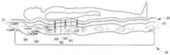
- FIG. 4is diagrammatic side view of the mattress and the topper of FIG. 2 showing a flow of air, moisture, and heat with respect to the mattress and the topper;
- FIG. 5is diagrammatic view of a control system of the person support system of FIG. 1 according to this disclosure.
- FIG. 6is a flow chart illustrating one optional procedure executed by the control system of FIG. 5 according to this disclosure.
- FIG. 7is a flow chart illustrating a second optional procedure executed by the control system of FIG. 5 according to this disclosure.
- FIG. 8is a flow chart illustrating a third optional procedure executed by the control system of FIG. 5 according to this disclosure.
- a control system for a person support systemis configured to receive a first set of input signals from an electronic medical record (EMR), generate a surface performance index as a function of interface pressure (P), shear (S), and temperature (T) based on the first set of inputs, receive a second set of input signals from the EMR, determine if the relative contributions of P, S, and/or T should be modified based on the second set of input signals while maintaining the performance index, and regulate a fluid supply as a function of P, S, and T.
- EMRelectronic medical record
- Pinterface pressure
- Sshear
- Ttemperature
- a control system for a person support systemis configured to receive a first set of input signals from an EMR, establish thresholds for interface pressure (P), shear (S), and temperature (T) based on the first set of inputs, receive a second set of input signals from a plurality of sensors corresponding to at least one of the bladder pressure, interface pressure, shear, temperature, and/or relative humidity of the tissue and/or person contacting surface, compare the sensed values with the corresponding thresholds, and regulate a fluid supply as a function of difference between the sensed P, S, and T values and the corresponding thresholds.
- Pinterface pressure
- Sshear
- Ttemperature
- a control system for a person support systemis configured to receive a set of input signals from a plurality of sensors corresponding to the relative humidity of the tissue and/or person contacting surface, look up the value of the relative humidity in a table to determine desired surface performance characteristics, and regulate a fluid supply as a function of surface performance characteristics.
- Pressure ulcerssometimes form in areas where a person's tissue is under stress.
- tissue break downSeveral factors have been identified as contributing to tissue break down. Some of the more widely accepted factors include mechanical stresses within the tissue, such as, compression, stretching and distortion of tissue caused by pressure and shear forces. Other factors, such as friction, body heat and moisture have also been identified as contributing to tissue break down.
- pressure ulcerswere thought to result from a single breakdown mechanism: interface pressure and shear force.
- wounds generally identified as pressure ulcerscan be broken down into different types of wounds resulting from at least two breakdown mechanisms. The first type can be a superficial lesion, which some studies suggest may not be the result of pressure at all and may never progress to deeper tissue layers.
- the second type of pressure ulceris of a type which a growing body of evidence strongly suggests is the result of deep tissue injury (DTI), driven by tissue deformation and ischemia in the skin and underlying areas of muscle and fat.
- DTIdeep tissue injury
- damage from the deformation alonecan be the primary mechanism of damage, independent of the ischemic process.
- the primary cause of breakdownis generally believed to be ischemia.
- the denominatoris representative of the total tissue mechanical stress at any combination of pressure P1 and shear S1 that cause full occlusion.
- the numeratorrepresents the total tissue mechanical stress under any set of arbitrary loading conditions.
- the expressioncan also be expressed in terms of the supply SPL of blood to the tissue as follows:
- Tissue demand for oxygenis reduced by approximately 6-13% per 1° C. that the tissue is cooled.
- the effect of altering the tissue temperature between two arbitrary temperatures To and T1can be expressed as follows:
- Tissue demand for oxygencan also be expressed as a function of the cooling power of surfaces in terms of total heat withdrawal (THW) rather than tissue temperature.
- TSWtotal heat withdrawal
- DMD T 1 DMD T 0( 1 + % ⁇ _reduction ⁇ _in ⁇ _tissue ⁇ _demand ) ( ( tissue_temp . _° ⁇ ⁇ C . W m 2 ) * T ⁇ ⁇ H ⁇ ⁇ W + 37.78 )
- the unloaded supply and unloaded demand valuesare compared to the measured supply and measured demand values as shown in the following equation:
- the multiple performance indicesare plotted in an N-dimensional visualization space and are analyzed using statistical methods to generate equations that provide a fit for the performance indices.
- the performance indicesare plotted in a 2-dimensional visualization space and/or analyzed using multiple variable regression techniques.
- a tableis generated containing the multiple surface performance indices with corresponding values of interface pressure, shear force, and temperature. The table is used as a look-up table.
- An example of a look-up table having surface performance index values calculated according to this disclosureis provided as follows:
- the person support system 10suitable for being controlled according to one or both of the analytical model and the statistical model is shown in FIG. 1 .
- the person support system 10includes a person support surface 12 , a fluid supply 14 , and a control system 16 .
- the person support system 10is used in the hospital setting and is supported on a person support apparatus (not shown), such as a hospital bed, stretcher, or other support structure. If desired, the person support system 10 can be supported on a floor (not shown), although typically, that is not intended to be the most common arrangement.
- the person support system 10is configured to help reduce the likelihood of developing pressure ulcers and/or superficial lesions by maintaining at least one of the interface pressure, temperature, moisture, shear force, and/or friction within predetermined ranges.
- the person support surface 12is configured to support a person thereon.
- the person support surface 12includes a mattress 18 and a mattress topper 20 as shown in FIGS. 1 and 2 .
- the mattress topper 20is integrated into the mattress 18 . That is, the mattress 18 and topper 20 are coupled together to form a support surface unit in some embodiments. In other embodiments, the mattress 18 is provided without the mattress topper 20 .
- the mattress 18 in the illustrative examplehas multiple zones, such as, a first zone Z 1 or head zone Z 1 , a second zone Z 2 or seat zone Z 2 , and a third zone Z 3 or foot zone Z 3 as shown in FIG. 3 . In some embodiments, the zones Z 1 -Z 3 are independently controlled by the fluid supply 14 .
- the mattress 18includes an outer mattress cover 22 or mattress ticking 22 that envelopes an area to define a mattress chamber 24 , and a mattress inlet 26 as shown in FIG. 2 .
- the mattress ticking 22has a support contacting surface 28 that contacts the person support apparatus (or floor), and a topper contacting surface 30 that interfaces with the mattress topper 20 .
- the topper contacting surface 30serves as a person contacting surface 30 where the mattress topper 20 is integrated into the mattress 18 , or the person support surface 12 does not include a mattress topper 20 .
- the mattress ticking 22is composed of a urethane and/or polytetrafluoroethylene (PTFE) coated nylons or other fabrics, for example. It is contemplated by this disclosure that the mattress ticking 22 can be made of other materials, such as those that are configured to prevent water from passing therethrough while allowing vapor to be transmitted therethrough.
- PTFEpolytetrafluoroethylene
- the mattress chamber 24contains a plurality of fluid bladders 32 and a mattress spacer 34 therein as shown in FIG. 2 .
- the mattress 18contains only one mattress bladder 32 within the mattress chamber 24 .
- the mattress 18is made of a polymeric material, such as, foam, foam blocks, foam layers of varying density, and/or include foam borders, which are used in combination with fluid bladders 32 in some embodiments, which fluid bladders themselves may or may not have internal foam.
- the bladders 32 and/or topper 20provide therapy and/or low air loss functionality through varying air pressure, blowing air, or exhausting air.
- the fluid bladders 32are gas bladders 32 that are alternately inflated and deflated and the mattress spacer 34 is made of foam and positioned between the fluid bladders 32 and the mattress ticking 22 .
- the bladders 32are arranged to form bladder arrays 36 that are positioned adjacent one another and/or on top of one another with the bladders 32 in the same or a different orientation.
- the bladders 32 and/or bladder arrays 36are in communication with one another such that the fluid pressure in the bladders 32 and/or bladder arrays 36 is maintained as pressure is exerted on the bladders 32 and/or bladder arrays 36 , e.g., supporting a person thereon.
- the bladders 32 or bladder arrays 36are connected together with a connector 38 that couples the bladders to the mattress inlet 26 .
- the bladders 32 and/or bladder arrays 36are configured, in some instances, to deliver therapy to a person supported on the person support surface 12 .
- the bladders 32 and/or bladder arrays 36deliver therapy through sequential pressure increases/decreases and/or rapid changes in pressure of the bladders 32 and/or bladder arrays 36 as shown in FIG. 3 .
- one or more sections of the surface 18may provide alternating pressure therapy, continuous lateral rotation therapy, boost assistance, percussion/vibration therapy, and/or turn assistance.
- the bladders 32 and/or bladder arrays 36exhaust gas into the mattress chamber 24 .
- the mattress topper 20is coupled to the mattress 18 and interfaces with the person supported on the person support surface 12 in some embodiments as shown in FIG. 4 .
- the mattress topper 20is a low air loss topper 20 .
- Low air-lossbroadly refers to a feature of a support surface that provides a flow of air to assist in managing the heat and humidity (microclimate) of the tissue contacting a surface.
- Diffusive evaporationevaporates accumulated moisture through and under the surface of the support device to cool the tissue without blowing air directly on the tissue.
- An example of a diffusive deviceis shown in FIG. 4 in which a person is lying on the support surface 12 in the supine position with fluid F 1 flowing through the support surface 12 to remove heat H 1 and moisture M 1 radiated by the person.
- a combination of diffusive and convective evaporationis used.
- the mattress topper 20includes a topper cover 40 or ticking 40 that defines a topper chamber 42 , a topper inlet 44 , a topper vent 46 , and a spacer 48 as shown in FIG. 3 .
- the topper ticking 40includes a mattress contacting surface 50 and a person contacting surface 52 .
- the mattress contacting surface 50interfaces with the topper contacting surface 30 .
- the person contacting surface 52interfaces with a person lying thereon.
- the mattress contacting surface 50 and the patient contacting surface 52are generally shaped to cooperate with the topper contacting surface 30 and are secured to one another along their respective edges by ultrasonic welding, for example, in order to form a substantially fluid-tight seal.
- the mattress contacting surface 50 and the patient contacting surface 52are secured to one another by adhesive, plastic welding, or other securing means, and are secured along various portions of the mattress contacting surface 50 and the patient contacting surface 52 .
- the ticking 50is vapor permeable and impermeable to both liquids and air. It is within the scope of this disclosure for the ticking 50 to be both vapor permeable and air permeable. In some embodiments, the mattress ticking 22 and the ticking 50 are made of the same material and have the same physical characteristics.
- the inlet 44is positioned along a side of the topper 20 and allows for fluid to be communicated from the control system 14 into the chamber 42 in the illustrative example as shown in FIGS. 2 and 3 .
- the inlet 44includes an inlet coupler that couples the control system 14 to the topper 20 such that there is a substantially fluid-tight seal between the inlet 44 and the topper 20 .
- the vent 46 or outlet 46is positioned along a side of the topper 20 opposite the inlet 44 in the illustrative embodiment as shown in FIG. 2 .
- the vent 46allows fluid entering the inlet 44 and passing through the chamber 42 to exit the topper 20 .
- the spacer 48is positioned within the chamber 42 and separates the mattress contacting surface 50 from the patient contacting surface 52 as shown in FIG. 2 . It is contemplated that, in some embodiments, the spacer 48 is made of material(s) having a high fluid porosity and having some resistance against flattening, while not being so stiff as to increase interface pressure too dramatically. In some embodiments, the spacer 32 includes at least one bladder (not shown). In some embodiments, the mattress spacer 34 and the spacer 48 are made of a similar material and/or have similar physical characteristics. The thickness of the spacer 48 is between about 0.1′′ and 0.75′′ in some embodiments. It should be appreciated that the thickness of the spacer 48 can be greater than 0.75′′ if desired.
- the fluid supply 14is configured to supply fluid to the bladders 32 , bladder arrays 36 , and/or the mattress topper 20 as shown in FIG. 1 .
- there are multiple fluid supplies 14with a first fluid supply supplying fluid to the bladders 32 or bladder arrays 36 and a second fluid supply 32 supplying fluid to the mattress topper 20 .
- the fluid supplies 14include a gas blower 14 that supplies air to the bladders 32 , bladder arrays 36 , and/or the mattress topper 20 . It is within the scope of this disclosure for the fluid supply 14 to supply various other gasses and/or liquids rather than air.
- the fluid supply 14is integrated into the mattress 16 .
- the fluid supply 14is coupled to a person support apparatus or supported on other supporting structures.
- the fluid supply 14supplies the fluid through a connector 54 to the inlet 26 of the mattress 16 and/or the inlet 44 of the mattress cover 20 in the illustrative example.
- the fluid supply 14is removably coupled to the inlet 26 of the mattress 16 and/or the inlet 44 of the mattress cover 20 through a hose 54 .
- the fluid supply 14includes a heating/cooling element (not shown) that can heat/cool the fluid being supplied.
- the control system 16 for person support system 10includes a plurality of sensors 56 and a controller 58 operatively coupled to the fluid supply 14 and the plurality of sensors 56 as shown in FIGS. 1 and 5 .
- the control system 16is configured to control various functions of the person support surface 12 , such as, administering therapy to a person supported on the person support surface 12 .
- the control system 16is configured to communicate information about the person support system 10 over a hospital network (not shown) and/or alert caregivers. At least a portion of the control system 16 is integrated into and/or coupled to the support surface 12 in some embodiments.
- the fluid supply 14 , the plurality of sensors 56 , and the controller 58are all incorporated within the person support surface 12 in some instances.
- the sensors 56are operatively coupled to the controller 58 and are configured to sense various parameters, including, but not limited to, a temperature of a tissue and/or the person contacting surface 52 , a relative humidity of the interface between a tissue and the person contacting surface 52 , an amount of shear between the person contacting surface 52 and the tissue, and a pressure of the fluid inside the bladders 32 .
- the sensors 56 and the controller 58are coupled to a network 60 and the controller 58 receives data signals from the sensors 56 over the network 60 .
- the sensors 56include temperature sensors 62 integrated into the person contacting surface 52 and configured to sense the temperature of a tissue contacting the person contacting surface 52 .
- the sensors 56include moisture sensors 64 integrated into the person contacting surface and configured to sense the relative humidity of the interface between a tissue and the person contacting surface 52 .
- the sensors 56are configured to generate analog and/or digital signals. In some embodiments, the sensors 56 generate an analog data signal and are connected directly to the controller 58 as shown in FIG. 5 . In other embodiments, the sensors 56 are configured to produce a digital data signal, e.g., a serial digital data signal, and can be connected to the network 60 , e.g., a Serial Peripheral Interface (SPI) network, to communicate with the controller 58 if desired.
- SPISerial Peripheral Interface
- the controller 58is configured to regulate the fluid supply 14 to control various characteristics of the person support surface 12 in response to data signals received from the sensors 56 and/or from a person's electronic medical record (EMR).
- EMRelectronic medical record
- the EMRis copied and stored locally on the controller 58 or in a memory location coupled to the network 60 .
- the controller 58is configured to regulate the fluid supply 14 in accordance with parameters identified in a look-up table using the data signals from the sensors 56 .
- the controller 58is configured to regulate the fluid supply 14 as a function of the data signals from the sensors 56 .
- the controller 58is configured to regulate the fluid supply 14 with parameters identified in a look-up table using information from the EMR of a person supported on the person support surface 12 . In still other contemplated embodiments, the controller 58 is configured to regulate the fluid supply 14 in accordance with both the data signals and the EMR information. Alternatively or additionally, the controller 58 is configured to regulate the fluid supply 14 in accordance with a user input.
- the controller 58can be located in a variety of places.
- the controller 58is incorporated into a graphical user interface (not shown) and is configured to receive user inputs, e.g., from a caregiver and/or person supported on the person support apparatus. It is contemplated by this disclosure that the graphical user interface is coupled to the person support apparatus or support structure or equipment management system.
- the controller 58is integrated into an external network (not shown), such as a hospital network.
- the controller 58is integrated into the fluid supply 14 .
- the controller 58includes memory 72 , shown in FIG. 5 , and stores data signals received from the sensors 56 in the memory 72 in some embodiments. In other embodiments, the memory 72 is separate from the controller 58 . Alternatively or additionally, the controller 58 receives one or more user input signals from a user input device (not shown) that allows the person (caregiver and/or person supported on the person support system 10 ) to influence the regulation of the fluid supply 14 . In some embodiments, the user input signal(s) is only able to influence the regulation of the fluid supply 14 within the predetermined ranges.
- the controller 58is configured to execute operating logic 76 that defines various control, management, and/or regulation functions.
- This operating logic 74is in the form of software, firmware, and/or dedicated hardware, such as, a series of programmed instructions, code, electronic files, or commands using general purpose or special purpose programming languages or programs executed on one or more general purpose or special purpose computers, processors, other control circuitry, or networks; a hardwired state machine; and/or a different form as would occur to those skilled in the art.
- the controller 58includes operating logic 74 in the form of procedure 76 for example, as shown in the flowchart of FIG. 6 .
- Procedure 76includes operations/conditionals as indicated at blocks 78 , 80 , 82 , 84 , and 86 .
- Procedure 76is used to regulate the fluid supply 14 as a function of the data signals from the interface pressure sensors 70 , the shear force sensors 66 , and the temperature sensors 62 .
- Procedure 76begins with the operation of block 78 wherein the controller 58 receives data from the EMR which data is indicative of the person's susceptibility to developing pressure ulcers and/or superficial lesions.
- the EMR dataincludes, for example, a person's height, weight, pressure ulcer history, superficial lesion history, medications being administered, medical conditions, skin condition, and/or resistance to friction and shear tearing forces.
- medicationslike Pamelor for depression or Pylocarpine for Glaucoma may cause a person to sweat at a lower skin temperature.
- the medication Prednisonewhich is used to combat inflammation, sometimes can significantly reduce the skin's resistance to friction and shear tearing forces.
- medical conditionssuch as, diabetes can inhibit a person's ability to sweat and lead to a higher skin temperature.
- the controller 58uses the EMR data to identify standard hospital specific protocols that are, in turn, used to establish threshold values for interface pressure, shear, and temperature for the particular person.
- the thresholdsare generic pre-programmed thresholds.
- the thresholdsare input by a user through the user interface and/or a remote location.
- threshold valuesare also established for friction and moisture.
- the sensors 56sense at least one of the interface pressure between the surface and a tissue, the amount of shear between the surface and the tissue, and the temperature of the tissue. In some embodiments, the sensors 56 also sense the moisture between the tissue and the person contacting surface 52 . Alternatively or additionally, one or more of the sensors 56 sense environmental conditions, such as, ambient temperature and humidity. The sensors 56 post the sensed information as a value or an event on the network 60 in some embodiments.
- the controller 58determines if it subscribes to the information on the network 60 and, if it does, it inputs the information into the operating logic 74 . For example, the controller 58 will elect to receive the data signal corresponding to the interface pressure, amount of shear, and the temperature in some embodiments. In the operation of block 86 , if the controller 58 determines in the conditional of block 84 that the controller 58 subscribes to the information, then the controller 58 compares the sensed information to corresponding threshold values.
- the controller 58regulates the fluid supply 14 as a function of the difference between the sensed value and the threshold value in the operation of block 90 .
- the controller 58looks up the difference between the threshold and the sensed value in a look-up table to determine the corresponding desirable support surface characteristics and/or support surface performance index. The controller 58 then proceeds to cause the fluid supply 14 to increase/decrease the pressure within the fluid bladders 32 as appropriate. It has been found that increasing the pressure in fluid bladders 32 helps reduce friction and therefore, helps reduce instances of superficial lesions. It has been found that decreasing the pressure in the fluid bladders 32 helps reduce the instances of pressure ulcers.
- the controller 58causes the fluid supply 14 to raise/lower the temperature of the fluid within the fluid bladders 32 and/or flowing through the mattress topper 20 . It has been found that lowering the temperature of the fluid flowing through the mattress cover 22 and/or the fluid contained within the fluid bladders 32 helps reduce instances of pressure ulcers and/or superficial lesions.
- the controller 58operates the fluid supply 14 so as to raise or lower the support surface performance index from a previous support surface performance index to a desirable support surface performance index.
- the controller 58operates the fluid supply 14 to maintain the existing support surface performance index while varying at least one of the interface pressure, shear force, and tissue temperature.
- the controller 58regulates the fluid supply 14 as a function of the EMR data and the sensor signals. Alternatively or additionally, the controller 58 receives a user input and regulates the fluid supply 14 as a function thereof. In some embodiments, the user input corresponds to a person's comfort level and is allowed to vary the surface performance index by ⁇ 5%. In still other embodiments, the controller 58 regulates the fluid supply 14 and the temperature of the fluid from the fluid supply 14 as a function of one or more environmental conditions, such as, ambient temperature and humidity.
- the controller 58includes operating logic 74 in the form of procedure 92 , for example, as shown in the flowchart of FIG. 7 .
- Procedure 92includes the operations/conditionals of blocks 94 , 96 , 98 , and 100 .
- Procedure 92is used to regulate the fluid supply 14 as a function of the coefficient of friction of the surface and data signals from the moisture sensors 56 in some embodiments. It is contemplated by this disclosure that the coefficient of friction for the surface is stored in the memory 72 . Alternatively or additionally, the coefficient of friction for the surface is entered by a user through a user interface. In some embodiments, the coefficients of friction for multiple surfaces are input into a table and a user (or the controller) selects the coefficient corresponding to the support surface 12 being used.
- Procedure 92begins with the operation of block 94 in which the sensors 56 sense the amount of moisture present at the interface between a tissue and a surface. The sensors 56 post the sensed information as a value or an event on the network 60 . In the conditional of block 96 , the controller 58 determines if it subscribes to the information on the network 60 , and if it does, it inputs the information into the operating logic 74 .
- the controller 58uses the information to determine a desirable set of support surface characteristics. In some embodiments, therefore, the controller 58 receives the data signal corresponding to the amount of moisture and determines a desirable set of support surface characteristics. In some embodiments, the controller 58 looks up the moisture value in a table and the corresponding coefficient of friction to determine the corresponding desirable support surface characteristics and/or support surface performance index. In some embodiments, the controller 58 calculates desirable support surface characteristics and/or support surface performance index as a function of the coefficient of friction and the amount of moisture.
- the controller 58regulates the fluid supply 14 as a function of the desirable support surface characteristics.
- the controller 58operates the fluid supply 14 to increase/decrease the pressure within the fluid bladders 32 .
- the controller 58operates the fluid supply 14 to raise/lower the temperature of the fluid within the fluid bladders 32 and/or flowing through the mattress topper 20 .
- the controller 58causes the fluid supply 14 to raise/lower the support surface performance index from a previous support surface performance index to the desirable support surface performance index.
- the controller 58operates the fluid supply 14 to maintain the existing support surface performance index while varying at least one of the amount of moisture (which can be accomplished by varying the temperature of the fluid flowing through the mattress cover 22 and/or the temperature of the fluid in the fluid bladders 32 ) and the coefficient of friction which can be modified by adjusting the firmness of the bladders 32 .
- the controller 58receives a user input and regulates the fluid supply 14 as a function thereof. It some embodiments, the user input corresponds to a person's comfort level and is allowed to vary the surface performance index by ⁇ 5%. In some embodiments, the controller 58 regulates the fluid supply 14 as a function of environmental conditions, such as, ambient temperature and humidity.
- the controller 58includes operating logic 74 in the form of procedure 102 , for example, as shown in the flowchart of FIG. 8 .
- Procedure 102includes the operations/conditionals of blocks 104 , 106 , 108 , 110 , 112 , and 114 .
- Procedure 102is used to regulate the fluid supply 14 as a function of data from the EMR of the person supported on the person support surface 12 .
- Procedure 102begins with the operation of block 104 in which the controller 58 receives a first set of information from the EMR corresponding to the person's susceptibility to developing pressure ulcers and/or superficial lesions.
- the first set of EMR informationcan include information, such as, for example, a Braden risk score, a person's height, weight, pressure ulcer history, superficial lesion history, and other similar information.
- the controller 58uses the first set of EMR information to calculate a surface performance index as a function of interface pressure, shear, and temperature.
- the controller 58looks up the first set of EMR information in a lookup table that identifies support surface characteristics and/or support surface performance indices.
- at least some of the values in the tableare based on the National Clearinghouse Guidelines.
- the surfacesare tested to determine the P, S, and T indices for each and then converted to a performance index, which may correspond to a single Braden risk score or range or risk scores, for example.
- the controller 58examines the Braden risk score to determine the level of risk the person is at and then identifies surfaces that have a performance index corresponding to the level of risk. In some embodiments, the controller 58 uses mathematical algorithms to calculate the support surface performance index as a function of interface pressure, shear, and temperature based on the first set of EMR information.
- the controller 58determines which person support surfaces 12 are appropriate for the person. In some embodiments, the controller 58 outputs the index to a display (not shown) and a caregiver selects the appropriately rated person support surface 12 . Alternatively or additionally, the controller 58 outputs a list of person support surfaces 12 rated at or above the index to a display (not shown). In some embodiments, the controller 58 is programmed with a surface identifier that includes a performance index that the person support surface is rated for, and alerts the caregiver, audibly or visually, whether the surface is rated at least one of below the index and greater than or equal to the index. In some embodiments, the controller 58 controls a person support surface 12 to change its initial performance index so that the person support surface 12 is operating at the calculated performance index.
- the controller 58receives a second set of information from the EMR corresponding to the person's medical information.
- the second set of EMR informationincludes medical information, such as, for example, a person's medical diagnosis information and/or history, current and/or previous medications, personal preferences, current superficial lesions, current pressure ulcers, and other similar information.
- the controller 58causes the fluid supply 14 to adjust the bladder 32 pressures and/or the temperature of the fluid in the bladders 32 and/or flowing through the mattress topper 20 to raise/lower the support surface performance index from an initial support surface performance index to the calculated support surface performance index based on these other parameters.
- the controller 58causes the fluid supply 14 to maintain the existing support surface performance index while varying the performance of the fluid supply 14 as a function of at least one of the interface pressure, shear force, and tissue temperature.
- the controller 58receives a user input and regulates the fluid supply 14 as a function thereof.
- the user inputcorresponds to a person's comfort level and is allowed to vary the surface performance index by ⁇ 5%.
- the controller 58regulates the fluid supply 14 as a function of environmental conditions, such as, ambient temperature and humidity.
Landscapes
- Health & Medical Sciences (AREA)
- Life Sciences & Earth Sciences (AREA)
- Animal Behavior & Ethology (AREA)
- Veterinary Medicine (AREA)
- Public Health (AREA)
- General Health & Medical Sciences (AREA)
- Nursing (AREA)
- Engineering & Computer Science (AREA)
- Pathology (AREA)
- Medical Informatics (AREA)
- Molecular Biology (AREA)
- Surgery (AREA)
- Heart & Thoracic Surgery (AREA)
- Biomedical Technology (AREA)
- Biophysics (AREA)
- Physics & Mathematics (AREA)
- Dentistry (AREA)
- Computer Networks & Wireless Communication (AREA)
- Oral & Maxillofacial Surgery (AREA)
- Dermatology (AREA)
- Invalid Beds And Related Equipment (AREA)
- Mattresses And Other Support Structures For Chairs And Beds (AREA)
- Accommodation For Nursing Or Treatment Tables (AREA)
- Measuring And Recording Apparatus For Diagnosis (AREA)
- Surgical Instruments (AREA)
Abstract
Description
reduction_in_tcpO2=√{square root over ((P2+S2))}
If the pressure at which perfusion can fully occluded (Pocclusion) is examined, then the proportional reduction in blood supply to a tissue at a pressure P1 and a shear S1 can be expressed as:
Given the previous equation, the effect of temperature on tissue demand for oxygen relative to demand in an uncovered, thermoneutral state can be expressed as follows:
The higher the ratio, the greater the likelihood that the surface helps prevent pressure ulcers and/or superficial lesions from developing.
| TABLE 1 |
| Support Surface Performance Table |
| Pressure | Shear | THW | Performance Index | |
| (mm Hg) | (mm Hg) | (W/sq. m) | (SPL/DMD) | |
| 32 | 0.6 | 250 | 0.97 | |
| Surface B | 47 | 2.2 | 87 | 0.40 |
| Surface C | 51 | 2.2 | 70 | 0.33 |
| Surface D | 52.5 | 3.2 | 62 | 0.31 |
| Surface E | 51 | 3.2 | 10 | 0.28 |
| Surface F | 56.5 | 2.9 | 53 | 0.26 |
| Surface G | 57 | 3.6 | 27 | 0.23 |
| 70 | 4 | 12 | 0.05 | |
It is contemplated by this disclosure that one or both of the analytical model and the statistical model is used, as desired, in ranking and/or controlling one or more functions of person support systems.
Claims (18)
Priority Applications (2)
| Application Number | Priority Date | Filing Date | Title |
|---|---|---|---|
| US12/881,249US8531307B2 (en) | 2009-09-18 | 2010-09-14 | Patient support surface index control |
| US14/019,002US9030331B2 (en) | 2009-09-18 | 2013-09-05 | Fluid supply control for patient support surface |
Applications Claiming Priority (2)
| Application Number | Priority Date | Filing Date | Title |
|---|---|---|---|
| US24362209P | 2009-09-18 | 2009-09-18 | |
| US12/881,249US8531307B2 (en) | 2009-09-18 | 2010-09-14 | Patient support surface index control |
Related Child Applications (1)
| Application Number | Title | Priority Date | Filing Date |
|---|---|---|---|
| US14/019,002ContinuationUS9030331B2 (en) | 2009-09-18 | 2013-09-05 | Fluid supply control for patient support surface |
Publications (2)
| Publication Number | Publication Date |
|---|---|
| US20110068939A1 US20110068939A1 (en) | 2011-03-24 |
| US8531307B2true US8531307B2 (en) | 2013-09-10 |
Family
ID=43383485
Family Applications (2)
| Application Number | Title | Priority Date | Filing Date |
|---|---|---|---|
| US12/881,249Active2031-11-03US8531307B2 (en) | 2009-09-18 | 2010-09-14 | Patient support surface index control |
| US14/019,002ActiveUS9030331B2 (en) | 2009-09-18 | 2013-09-05 | Fluid supply control for patient support surface |
Family Applications After (1)
| Application Number | Title | Priority Date | Filing Date |
|---|---|---|---|
| US14/019,002ActiveUS9030331B2 (en) | 2009-09-18 | 2013-09-05 | Fluid supply control for patient support surface |
Country Status (3)
| Country | Link |
|---|---|
| US (2) | US8531307B2 (en) |
| EP (2) | EP2901994B1 (en) |
| JP (2) | JP5710191B2 (en) |
Cited By (9)
| Publication number | Priority date | Publication date | Assignee | Title |
|---|---|---|---|---|
| US20110247143A1 (en)* | 2008-04-15 | 2011-10-13 | Richards Sandy M | Temperature and moisture regulating topper for non-powered person-support surfaces |
| US20140331412A1 (en)* | 2008-03-15 | 2014-11-13 | Stryker Corporation | Force sensing sheet |
| US9030331B2 (en) | 2009-09-18 | 2015-05-12 | Hill-Rom Services, Inc. | Fluid supply control for patient support surface |
| US9333136B2 (en) | 2013-02-28 | 2016-05-10 | Hill-Rom Services, Inc. | Sensors in a mattress cover |
| WO2018035604A1 (en)* | 2016-08-21 | 2018-03-01 | Mobisafe Systems Inc. | Inflatable cellular cushioning device for body support |
| US10531996B2 (en) | 2015-11-06 | 2020-01-14 | Andrei Cernasov | Supporting surface with programmable supports and method to reduce pressure on selected areas of a body |
| US10765577B2 (en) | 2015-06-30 | 2020-09-08 | Hill-Rom Services, Inc. | Microclimate system for a patient support apparatus |
| US20210038455A1 (en)* | 2019-08-08 | 2021-02-11 | Simbex Llc | Method for reducing tissue interface pressure |
| US11540964B2 (en)* | 2018-02-27 | 2023-01-03 | Hill-Rom Services, Inc. | Patient support surface control, end of life indication, and x-ray cassette sleeve |
Families Citing this family (53)
| Publication number | Priority date | Publication date | Assignee | Title |
|---|---|---|---|---|
| US8533879B1 (en)* | 2008-03-15 | 2013-09-17 | Stryker Corporation | Adaptive cushion method and apparatus for minimizing force concentrations on a human body |
| JP4961522B2 (en)* | 2008-09-21 | 2012-06-27 | 善雄 鈴木 | Eco sleep bedding |
| US20110301432A1 (en)* | 2010-06-07 | 2011-12-08 | Riley Carl W | Apparatus for supporting and monitoring a person |
| US9295600B2 (en)* | 2011-04-08 | 2016-03-29 | Hill-Rom Services, Inc. | Person support apparatus with activity and mobility sensing |
| AU2012202456A1 (en)* | 2011-05-03 | 2012-11-22 | Hill-Rom Services, Inc. | Temperature and moisture regulating topper for non-powered person-support surfaces |
| US8826473B2 (en) | 2011-07-19 | 2014-09-09 | Hill-Rom Services, Inc. | Moisture detection system |
| DE102011118758B4 (en)* | 2011-08-29 | 2013-08-29 | Thomas Sefrin | Lifting device for an aircraft |
| US8966997B2 (en) | 2011-10-12 | 2015-03-03 | Stryker Corporation | Pressure sensing mat |
| US8701230B2 (en)* | 2011-10-25 | 2014-04-22 | Hill-Rom Services, Inc. | Core instability system |
| AU2012331625B2 (en)* | 2011-11-03 | 2015-04-23 | Shl Healthcare Ab | Mattress system |
| US20140366277A1 (en)* | 2012-01-26 | 2014-12-18 | Huntleigh Technology Limited | Pressure measurement systems and methods with moisture vapor control |
| US20130212808A1 (en)* | 2012-02-21 | 2013-08-22 | Charles A. Lachenbruch | Topper with Targeted Fluid Flow Distribution |
| US9131780B2 (en) | 2012-02-14 | 2015-09-15 | Hill-Rom Services, Inc. | Topper with preferential fluid flow distribution |
| EP2667313B1 (en)* | 2012-05-22 | 2021-08-04 | Hill-Rom Services, Inc. | Adverse condition detection, assessment, and response system |
| US9572433B2 (en) | 2012-08-15 | 2017-02-21 | Hill-Rom Services, Inc. | Systems and methods for directing fluid flow in a mattress |
| US9468307B2 (en) | 2012-09-05 | 2016-10-18 | Stryker Corporation | Inflatable mattress and control methods |
| US8904876B2 (en) | 2012-09-29 | 2014-12-09 | Stryker Corporation | Flexible piezocapacitive and piezoresistive force and pressure sensors |
| US8997588B2 (en) | 2012-09-29 | 2015-04-07 | Stryker Corporation | Force detecting mat with multiple sensor types |
| GB201219632D0 (en)* | 2012-10-31 | 2012-12-12 | Univ Southampton | Apparatus for sensing and measuring pressure and shear components of a force at an interface between two surfaces |
| US8839473B1 (en)* | 2012-11-13 | 2014-09-23 | Alex Catala | Air mattress comfort adjustment system |
| US9433300B2 (en) | 2013-02-28 | 2016-09-06 | Hill-Rom Services, Inc. | Topper for a patient surface |
| US9693920B2 (en) | 2013-11-27 | 2017-07-04 | Sage Products, Llc | Apparatus and system for turning and positioning a patient |
| CN105249934A (en)* | 2014-07-18 | 2016-01-20 | 凯健企业股份有限公司 | Method for obtaining living body dynamic information and device for obtaining and converting living body dynamic information |
| US9808194B2 (en)* | 2014-09-25 | 2017-11-07 | Prs Medical Technologies, Inc. | Cushioning support for monitoring user activity |
| US10251593B2 (en)* | 2015-02-06 | 2019-04-09 | Binay Sugla | System and method for prevention of pressure ulcers |
| US9913770B2 (en)* | 2015-02-17 | 2018-03-13 | Hill-Rom Services, Inc. | Climate management topper with shape change actuators for regulating coolant distribution |
| KR101655199B1 (en) | 2015-02-27 | 2016-09-07 | 현대자동차 주식회사 | Ventilation bed and controling method of a vehicle |
| EP3482734B1 (en)* | 2015-06-15 | 2020-12-09 | Allen Medical Systems, Inc. | Spine table positioner pad with pressure sensing and cooling features |
| US10765576B2 (en) | 2015-08-18 | 2020-09-08 | Sage Products, Llc | Apparatus and system for boosting, transferring, turning and positioning a patient |
| US9849053B2 (en) | 2015-08-18 | 2017-12-26 | Sage Products, Llc | Apparatus and system for boosting, transferring, turning and positioning a patient |
| US11020295B2 (en) | 2015-12-22 | 2021-06-01 | Stryker Corporation | Patient support systems and methods for assisting caregivers with patient care |
| US10489661B1 (en) | 2016-03-08 | 2019-11-26 | Ocuvera LLC | Medical environment monitoring system |
| US10813806B2 (en) | 2016-05-24 | 2020-10-27 | Stryker Corporation | Medical support apparatus with stand assistance |
| WO2017214188A1 (en) | 2016-06-06 | 2017-12-14 | University Of Massachusetts | Systems and methods for prevention of pressure ulcers |
| US20180000633A1 (en)* | 2016-07-01 | 2018-01-04 | Hill-Rom Services, Inc. | Microclimate management system with wireless sensors |
| CN106175263A (en)* | 2016-07-09 | 2016-12-07 | 贾晓静 | A kind of intelligence mattress |
| US20180125414A1 (en)* | 2016-11-10 | 2018-05-10 | Stryker Corporation | Patient support apparatuses with mobility assessment |
| AU2017279786B2 (en) | 2016-12-27 | 2023-04-13 | Stryker Corporation | Variable speed patient transfer apparatus |
| US10600204B1 (en) | 2016-12-28 | 2020-03-24 | Ocuvera | Medical environment bedsore detection and prevention system |
| US10945679B2 (en) | 2017-01-31 | 2021-03-16 | Welch Allyn, Inc. | Modular monitoring smart bed |
| WO2018232012A1 (en) | 2017-06-13 | 2018-12-20 | Sage Products, Llc | Patient positioning and support system |
| CN107468463A (en)* | 2017-09-04 | 2017-12-15 | 丁燕 | A kind of nursing pad for being used to prevent pressure ulcer |
| WO2020041493A1 (en) | 2018-08-21 | 2020-02-27 | Sage Products, Llc | Systems and methods for lifting and positioning a patient |
| PL4076329T3 (en)* | 2019-12-18 | 2025-07-28 | Raye's, Inc. Dba Sizewise Manufacturing | Support surface overlay with vacuum enclosure |
| US11963916B2 (en) | 2019-12-30 | 2024-04-23 | Stryker Corporation | Track assembly for patient transport apparatus |
| US11938068B2 (en) | 2019-12-30 | 2024-03-26 | Stryker Corporation | Patient transport apparatus drive systems |
| US11679045B2 (en) | 2019-12-30 | 2023-06-20 | Stryker Corporation | Patient transport apparatus user interface |
| US12042268B2 (en)* | 2020-03-31 | 2024-07-23 | Hill-Rom Services, Inc. | Patient body monitoring using radar |
| EP3981322A1 (en)* | 2020-09-28 | 2022-04-13 | Hill-Rom Services, Inc. | Automatically identifying pressure injuries |
| GB2603171B (en)* | 2021-01-28 | 2023-11-15 | The Helping Hand Company Ledbury Ltd | A pressure monitoring cushion, system and method |
| WO2022231953A1 (en)* | 2021-04-29 | 2022-11-03 | Holtquist Zachariah Clarence | Mattress |
| US11890240B2 (en) | 2021-04-30 | 2024-02-06 | Sage Products, Llc | Method and device for turning and positioning a patient using fillable chambers |
| US20230034389A1 (en)* | 2021-07-30 | 2023-02-02 | TurnCare, Inc. | Interactive controllers for managing pressure-mitigation devices and approaches to facilitating engagement by users |
Citations (25)
| Publication number | Priority date | Publication date | Assignee | Title |
|---|---|---|---|---|
| US5970789A (en) | 1996-11-20 | 1999-10-26 | Hill-Rom, Inc. | Method and apparatus for evaluating a support surface |
| WO2000024353A1 (en) | 1998-10-28 | 2000-05-04 | Hill-Rom, Inc. | Force optimization surface apparatus and method |
| US6165142A (en) | 1998-09-21 | 2000-12-26 | Roho, Inc. | Biomedical apparatus |
| US6516483B1 (en)* | 2000-03-28 | 2003-02-11 | The Or Group, Inc. | Patient support surface |
| US6560804B2 (en)* | 1997-11-24 | 2003-05-13 | Kci Licensing, Inc. | System and methods for mattress control in relation to patient distance |
| US6721980B1 (en) | 1998-10-28 | 2004-04-20 | Hill-Fom Services, Inc. | Force optimization surface apparatus and method |
| US20050076715A1 (en) | 2003-10-13 | 2005-04-14 | Kuklis Matthew M. | Shear sensor apparatus |
| US20050288749A1 (en) | 2004-06-08 | 2005-12-29 | Lachenbruch Charles A | Heat wick for skin cooling |
| US7090648B2 (en) | 2000-09-28 | 2006-08-15 | Non-Invasive Monitoring Systems, Inc. | External addition of pulses to fluid channels of body to release or suppress endothelial mediators and to determine effectiveness of such intervention |
| US7107642B2 (en) | 2003-03-12 | 2006-09-19 | Jetta Company Limited | Adjustable mattress and pillow system |
| US7111346B2 (en) | 2002-05-15 | 2006-09-26 | Non-Invasive Monitoring Systems, Inc. | Reciprocating movement platform for the external addition of pulses of the fluid channels of a subject |
| WO2007008831A2 (en) | 2005-07-08 | 2007-01-18 | Hill-Rom, Inc. | Control unit for patient support |
| US7219380B2 (en)* | 2005-04-22 | 2007-05-22 | R&D Products, Llc | Multicompartmented air mattress |
| US20070135878A1 (en) | 2003-06-13 | 2007-06-14 | Lachenbruch Charles A | Self-powered steady-state skin-cooling support surfaces |
| US20080015665A1 (en) | 2004-02-10 | 2008-01-17 | Lachenbruch Charles A | Heat wick for skin cooling |
| US20080028533A1 (en) | 2006-08-04 | 2008-02-07 | Stacy Richard B | Patient Support |
| US7409735B2 (en) | 2004-08-16 | 2008-08-12 | Hill-Rom Services, Inc. | Dynamic cellular person support surface |
| US7459645B2 (en) | 2003-12-12 | 2008-12-02 | Hill-Rom Services, Inc. | Seat force sensor for a patient support |
| US20090217460A1 (en) | 2005-07-08 | 2009-09-03 | Bobey John A | Patient support |
| US20100043143A1 (en)* | 2007-04-30 | 2010-02-25 | Span-America Medical Systems, Inc. | Low air loss moisture control mattress overlay |
| US20100274331A1 (en) | 2009-04-28 | 2010-10-28 | Rachel Williamson | Microclimate management system |
| US7825814B2 (en) | 2002-07-17 | 2010-11-02 | Hill-Rom Services, Inc. | Bed occupant monitoring system |
| US20110163885A1 (en)* | 2005-08-10 | 2011-07-07 | Craig Poulos | Adjustable therapeutic mattress |
| US8087113B2 (en)* | 2005-05-12 | 2012-01-03 | Hunteigh Technology Limited | Inflatable support |
| US20120174322A1 (en)* | 2005-06-10 | 2012-07-12 | Skinner Andrew F | Control for pressurized bladder in a patient support apparatus |
Family Cites Families (19)
| Publication number | Priority date | Publication date | Assignee | Title |
|---|---|---|---|---|
| DE69032563T2 (en)* | 1990-11-06 | 1998-12-24 | Sunrise Medical Ccg Inc., Stevens Point, Wis. | MATTRESS FILLED WITH A FLUID |
| JPH06238097A (en)* | 1993-02-19 | 1994-08-30 | Matsushita Electric Ind Co Ltd | Bed pad device |
| US5630238A (en)* | 1995-08-04 | 1997-05-20 | Hill-Rom, Inc. | Bed with a plurality of air therapy devices, having control modules and an electrical communication network |
| JP2000000274A (en)* | 1998-06-17 | 2000-01-07 | Ichinomiya Orimono:Kk | Sanitary materials |
| US10357114B2 (en)* | 1999-04-20 | 2019-07-23 | Wcw, Inc. | Inflatable cushioning device with manifold system |
| US6155142A (en)* | 1999-08-13 | 2000-12-05 | B!G Ventures, Llc | Pliers with force augmentation and self-adjustment capability |
| GB2346553B (en)* | 2000-04-29 | 2001-01-10 | Sareo Healthcare Ltd | A mattress |
| US7378975B1 (en)* | 2000-06-09 | 2008-05-27 | Bed-Check Corporation | Method and apparatus for mitigating the risk of pressure sores |
| US7030764B2 (en)* | 2000-06-09 | 2006-04-18 | Bed-Check Corporation | Apparatus and method for reducing the risk of decubitus ulcers |
| JP2003339805A (en)* | 2002-05-28 | 2003-12-02 | Matsushita Electric Works Ltd | Mat-like apparatus |
| JP4712385B2 (en)* | 2002-09-06 | 2011-06-29 | ヒル−ロム サービシーズ,インコーポレイティド | Hospital bed |
| EP1553908A1 (en)* | 2002-10-23 | 2005-07-20 | Tcam Technologies, Inc. | Smart decubitus mat |
| SE524903C2 (en)* | 2003-02-04 | 2004-10-19 | Hilding Anders Internat Ab | Device and method for regulating physical properties of a bed |
| JP2005342443A (en)* | 2004-06-07 | 2005-12-15 | Saitama Prefecture | Slippage detecting system and method |
| WO2007060000A2 (en)* | 2005-11-25 | 2007-05-31 | Boehm Stephan | Device and method for carefully settling a patient in a defined position |
| US8220090B2 (en)* | 2006-10-26 | 2012-07-17 | Kap Medical | Multi-chamber air distribution support surface product and method |
| JP2009157479A (en)* | 2007-12-25 | 2009-07-16 | Shigadry With Earth:Kk | Bed environment monitoring system for cared person |
| US8525680B2 (en)* | 2009-09-18 | 2013-09-03 | Hill-Rom Services, Inc. | Apparatuses for supporting and monitoring a condition of a person |
| US8531307B2 (en) | 2009-09-18 | 2013-09-10 | Hill-Rom Services, Inc. | Patient support surface index control |
- 2010
- 2010-09-14USUS12/881,249patent/US8531307B2/enactiveActive
- 2010-09-15EPEP15161193.6Apatent/EP2901994B1/enactiveActive
- 2010-09-15EPEP20100176760patent/EP2298264B1/enactiveActive
- 2010-09-17JPJP2010209465Apatent/JP5710191B2/ennot_activeExpired - Fee Related
- 2013
- 2013-09-05USUS14/019,002patent/US9030331B2/enactiveActive
- 2015
- 2015-03-03JPJP2015041036Apatent/JP6007268B2/enactiveActive
Patent Citations (30)
| Publication number | Priority date | Publication date | Assignee | Title |
|---|---|---|---|---|
| US5970789A (en) | 1996-11-20 | 1999-10-26 | Hill-Rom, Inc. | Method and apparatus for evaluating a support surface |
| US6560804B2 (en)* | 1997-11-24 | 2003-05-13 | Kci Licensing, Inc. | System and methods for mattress control in relation to patient distance |
| US6165142A (en) | 1998-09-21 | 2000-12-26 | Roho, Inc. | Biomedical apparatus |
| US7515059B2 (en) | 1998-10-28 | 2009-04-07 | Hill-Rom Services, Inc. | Patient support surface with physiological sensors |
| WO2000024353A1 (en) | 1998-10-28 | 2000-05-04 | Hill-Rom, Inc. | Force optimization surface apparatus and method |
| US6721980B1 (en) | 1998-10-28 | 2004-04-20 | Hill-Fom Services, Inc. | Force optimization surface apparatus and method |
| US7330127B2 (en) | 1998-10-28 | 2008-02-12 | Hill-Rom Services, Inc. | Force optimization surface apparatus and method |
| US6516483B1 (en)* | 2000-03-28 | 2003-02-11 | The Or Group, Inc. | Patient support surface |
| US7090648B2 (en) | 2000-09-28 | 2006-08-15 | Non-Invasive Monitoring Systems, Inc. | External addition of pulses to fluid channels of body to release or suppress endothelial mediators and to determine effectiveness of such intervention |
| US7111346B2 (en) | 2002-05-15 | 2006-09-26 | Non-Invasive Monitoring Systems, Inc. | Reciprocating movement platform for the external addition of pulses of the fluid channels of a subject |
| US7228576B2 (en) | 2002-05-15 | 2007-06-12 | Non-Invasive Monitoring Systems, Inc. | Reciprocating movement platform for the external addition of pulses to the fluid channels of a subject |
| US7825814B2 (en) | 2002-07-17 | 2010-11-02 | Hill-Rom Services, Inc. | Bed occupant monitoring system |
| US7107642B2 (en) | 2003-03-12 | 2006-09-19 | Jetta Company Limited | Adjustable mattress and pillow system |
| US20070135878A1 (en) | 2003-06-13 | 2007-06-14 | Lachenbruch Charles A | Self-powered steady-state skin-cooling support surfaces |
| US20050076715A1 (en) | 2003-10-13 | 2005-04-14 | Kuklis Matthew M. | Shear sensor apparatus |
| US7714238B2 (en) | 2003-12-12 | 2010-05-11 | Hill-Rom Services, Inc. | Mattress seat force sensing method |
| US7459645B2 (en) | 2003-12-12 | 2008-12-02 | Hill-Rom Services, Inc. | Seat force sensor for a patient support |
| US20080015665A1 (en) | 2004-02-10 | 2008-01-17 | Lachenbruch Charles A | Heat wick for skin cooling |
| US20050288749A1 (en) | 2004-06-08 | 2005-12-29 | Lachenbruch Charles A | Heat wick for skin cooling |
| US7409735B2 (en) | 2004-08-16 | 2008-08-12 | Hill-Rom Services, Inc. | Dynamic cellular person support surface |
| US7219380B2 (en)* | 2005-04-22 | 2007-05-22 | R&D Products, Llc | Multicompartmented air mattress |
| US8087113B2 (en)* | 2005-05-12 | 2012-01-03 | Hunteigh Technology Limited | Inflatable support |
| US20120174322A1 (en)* | 2005-06-10 | 2012-07-12 | Skinner Andrew F | Control for pressurized bladder in a patient support apparatus |
| US20090217460A1 (en) | 2005-07-08 | 2009-09-03 | Bobey John A | Patient support |
| WO2007008831A2 (en) | 2005-07-08 | 2007-01-18 | Hill-Rom, Inc. | Control unit for patient support |
| US20110163885A1 (en)* | 2005-08-10 | 2011-07-07 | Craig Poulos | Adjustable therapeutic mattress |
| US20080028533A1 (en) | 2006-08-04 | 2008-02-07 | Stacy Richard B | Patient Support |
| US20100132116A1 (en) | 2006-08-04 | 2010-06-03 | Stacy Richard B | Patient Support with Orientation Sensitive Air Bladder Control |
| US20100043143A1 (en)* | 2007-04-30 | 2010-02-25 | Span-America Medical Systems, Inc. | Low air loss moisture control mattress overlay |
| US20100274331A1 (en) | 2009-04-28 | 2010-10-28 | Rachel Williamson | Microclimate management system |
Non-Patent Citations (1)
| Title |
|---|
| European Search Report for Application No. 10176760.6, dated Apr. 9, 2012, 6 pages. |
Cited By (14)
| Publication number | Priority date | Publication date | Assignee | Title |
|---|---|---|---|---|
| US20140331412A1 (en)* | 2008-03-15 | 2014-11-13 | Stryker Corporation | Force sensing sheet |
| US9642470B2 (en)* | 2008-03-15 | 2017-05-09 | Stryker Corporation | Force sensing sheet |
| US8856993B2 (en)* | 2008-04-15 | 2014-10-14 | Hill-Rom Services, Inc. | Temperature and moisture regulating topper for non-powered person-support surfaces |
| US20110247143A1 (en)* | 2008-04-15 | 2011-10-13 | Richards Sandy M | Temperature and moisture regulating topper for non-powered person-support surfaces |
| US9030331B2 (en) | 2009-09-18 | 2015-05-12 | Hill-Rom Services, Inc. | Fluid supply control for patient support surface |
| US11684529B2 (en) | 2013-02-28 | 2023-06-27 | Hill-Rom Services, Inc. | Mattress cover sensor method |
| US9333136B2 (en) | 2013-02-28 | 2016-05-10 | Hill-Rom Services, Inc. | Sensors in a mattress cover |
| US10765577B2 (en) | 2015-06-30 | 2020-09-08 | Hill-Rom Services, Inc. | Microclimate system for a patient support apparatus |
| US10531996B2 (en) | 2015-11-06 | 2020-01-14 | Andrei Cernasov | Supporting surface with programmable supports and method to reduce pressure on selected areas of a body |
| WO2018035604A1 (en)* | 2016-08-21 | 2018-03-01 | Mobisafe Systems Inc. | Inflatable cellular cushioning device for body support |
| US11191367B2 (en) | 2016-08-21 | 2021-12-07 | Mobisafe Systems Inc. | Inflatable cellular cushioning device for body support |
| US11540964B2 (en)* | 2018-02-27 | 2023-01-03 | Hill-Rom Services, Inc. | Patient support surface control, end of life indication, and x-ray cassette sleeve |
| US20210038455A1 (en)* | 2019-08-08 | 2021-02-11 | Simbex Llc | Method for reducing tissue interface pressure |
| US12064383B2 (en)* | 2019-08-08 | 2024-08-20 | Sizewise Rentals, L.L.C. | Method for reducing tissue interface pressure |
Also Published As
| Publication number | Publication date |
|---|---|
| US20140007346A1 (en) | 2014-01-09 |
| US9030331B2 (en) | 2015-05-12 |
| EP2901994A1 (en) | 2015-08-05 |
| EP2901994B1 (en) | 2016-09-14 |
| JP6007268B2 (en) | 2016-10-12 |
| EP2298264A3 (en) | 2012-10-03 |
| JP2011067626A (en) | 2011-04-07 |
| JP2015120027A (en) | 2015-07-02 |
| EP2298264B1 (en) | 2015-04-01 |
| EP2298264A2 (en) | 2011-03-23 |
| US20110068939A1 (en) | 2011-03-24 |
| JP5710191B2 (en) | 2015-04-30 |
Similar Documents
| Publication | Publication Date | Title |
|---|---|---|
| US8531307B2 (en) | Patient support surface index control | |
| US11322258B2 (en) | Adverse condition detection, assessment, and response systems, methods and devices | |
| US10583058B2 (en) | Person support apparatus having physiological sensor | |
| US20200360207A1 (en) | Adverse event mitigation systems, methods, and devices | |
| EP2702966B1 (en) | Microclimate management system | |
| US10660807B2 (en) | Systems, methods, and devices for the treatment of sleep disorders | |
| EP3056178B1 (en) | Predicting the onset of an adverse condition for a person on a support apparatus based on bed frame status input | |
| EP2982358B1 (en) | Systems, methods, and devices for treatment of sleep disorders | |
| US20200253387A1 (en) | Method for optimizing skin cooling level of an occupant support surface | |
| US20230000261A1 (en) | Pressurized Vertical Cylinder Air Chamber Mattress |
Legal Events
| Date | Code | Title | Description |
|---|---|---|---|
| AS | Assignment | Owner name:HILL-ROM SERVICES, INC., DELAWARE Free format text:ASSIGNMENT OF ASSIGNORS INTEREST;ASSIGNOR:LACHENBRUCH, CHARLES A.;REEL/FRAME:025171/0115 Effective date:20101020 | |
| AS | Assignment | Owner name:HILL-ROM SERVICES, INC. (INDIANA CORPORATION), IND Free format text:CHANGE OF STATE OF INCORPORATION FROM DELAWARE TO INDIANA;ASSIGNOR:HILL-ROM SERVICES, INC. (DELAWARE CORPORATION);REEL/FRAME:030983/0350 Effective date:20101228 | |
| STCF | Information on status: patent grant | Free format text:PATENTED CASE | |
| AS | Assignment | Owner name:JPMORGAN CHASE BANK, N.A., AS COLLATERAL AGENT, ILLINOIS Free format text:SECURITY INTEREST;ASSIGNORS:ALLEN MEDICAL SYSTEMS, INC.;HILL-ROM SERVICES, INC.;ASPEN SURGICAL PRODUCTS, INC.;AND OTHERS;REEL/FRAME:036582/0123 Effective date:20150908 Owner name:JPMORGAN CHASE BANK, N.A., AS COLLATERAL AGENT, IL Free format text:SECURITY INTEREST;ASSIGNORS:ALLEN MEDICAL SYSTEMS, INC.;HILL-ROM SERVICES, INC.;ASPEN SURGICAL PRODUCTS, INC.;AND OTHERS;REEL/FRAME:036582/0123 Effective date:20150908 | |
| AS | Assignment | Owner name:JPMORGAN CHASE BANK, N.A., AS COLLATERAL AGENT, ILLINOIS Free format text:SECURITY AGREEMENT;ASSIGNORS:HILL-ROM SERVICES, INC.;ASPEN SURGICAL PRODUCTS, INC.;ALLEN MEDICAL SYSTEMS, INC.;AND OTHERS;REEL/FRAME:040145/0445 Effective date:20160921 Owner name:JPMORGAN CHASE BANK, N.A., AS COLLATERAL AGENT, IL Free format text:SECURITY AGREEMENT;ASSIGNORS:HILL-ROM SERVICES, INC.;ASPEN SURGICAL PRODUCTS, INC.;ALLEN MEDICAL SYSTEMS, INC.;AND OTHERS;REEL/FRAME:040145/0445 Effective date:20160921 | |
| FPAY | Fee payment | Year of fee payment:4 | |
| AS | Assignment | Owner name:WELCH ALLYN, INC., NEW YORK Free format text:RELEASE BY SECURED PARTY;ASSIGNOR:JPMORGAN CHASE BANK, N.A.;REEL/FRAME:050254/0513 Effective date:20190830 Owner name:MORTARA INSTRUMENT, INC., WISCONSIN Free format text:RELEASE BY SECURED PARTY;ASSIGNOR:JPMORGAN CHASE BANK, N.A.;REEL/FRAME:050254/0513 Effective date:20190830 Owner name:HILL-ROM COMPANY, INC., ILLINOIS Free format text:RELEASE BY SECURED PARTY;ASSIGNOR:JPMORGAN CHASE BANK, N.A.;REEL/FRAME:050254/0513 Effective date:20190830 Owner name:MORTARA INSTRUMENT SERVICES, INC., WISCONSIN Free format text:RELEASE BY SECURED PARTY;ASSIGNOR:JPMORGAN CHASE BANK, N.A.;REEL/FRAME:050254/0513 Effective date:20190830 Owner name:ALLEN MEDICAL SYSTEMS, INC., ILLINOIS Free format text:RELEASE BY SECURED PARTY;ASSIGNOR:JPMORGAN CHASE BANK, N.A.;REEL/FRAME:050254/0513 Effective date:20190830 Owner name:VOALTE, INC., FLORIDA Free format text:RELEASE BY SECURED PARTY;ASSIGNOR:JPMORGAN CHASE BANK, N.A.;REEL/FRAME:050254/0513 Effective date:20190830 Owner name:HILL-ROM SERVICES, INC., ILLINOIS Free format text:RELEASE BY SECURED PARTY;ASSIGNOR:JPMORGAN CHASE BANK, N.A.;REEL/FRAME:050254/0513 Effective date:20190830 Owner name:ANODYNE MEDICAL DEVICE, INC., FLORIDA Free format text:RELEASE BY SECURED PARTY;ASSIGNOR:JPMORGAN CHASE BANK, N.A.;REEL/FRAME:050254/0513 Effective date:20190830 Owner name:HILL-ROM, INC., ILLINOIS Free format text:RELEASE BY SECURED PARTY;ASSIGNOR:JPMORGAN CHASE BANK, N.A.;REEL/FRAME:050254/0513 Effective date:20190830 | |
| AS | Assignment | Owner name:JPMORGAN CHASE BANK, N.A., ILLINOIS Free format text:SECURITY AGREEMENT;ASSIGNORS:HILL-ROM HOLDINGS, INC.;HILL-ROM, INC.;HILL-ROM SERVICES, INC.;AND OTHERS;REEL/FRAME:050260/0644 Effective date:20190830 | |
| MAFP | Maintenance fee payment | Free format text:PAYMENT OF MAINTENANCE FEE, 8TH YEAR, LARGE ENTITY (ORIGINAL EVENT CODE: M1552); ENTITY STATUS OF PATENT OWNER: LARGE ENTITY Year of fee payment:8 | |
| AS | Assignment | Owner name:HILL-ROM HOLDINGS, INC., ILLINOIS Free format text:RELEASE OF SECURITY INTEREST AT REEL/FRAME 050260/0644;ASSIGNOR:JPMORGAN CHASE BANK, N.A.;REEL/FRAME:058517/0001 Effective date:20211213 Owner name:BARDY DIAGNOSTICS, INC., ILLINOIS Free format text:RELEASE OF SECURITY INTEREST AT REEL/FRAME 050260/0644;ASSIGNOR:JPMORGAN CHASE BANK, N.A.;REEL/FRAME:058517/0001 Effective date:20211213 Owner name:VOALTE, INC., FLORIDA Free format text:RELEASE OF SECURITY INTEREST AT REEL/FRAME 050260/0644;ASSIGNOR:JPMORGAN CHASE BANK, N.A.;REEL/FRAME:058517/0001 Effective date:20211213 Owner name:HILL-ROM, INC., ILLINOIS Free format text:RELEASE OF SECURITY INTEREST AT REEL/FRAME 050260/0644;ASSIGNOR:JPMORGAN CHASE BANK, N.A.;REEL/FRAME:058517/0001 Effective date:20211213 Owner name:WELCH ALLYN, INC., NEW YORK Free format text:RELEASE OF SECURITY INTEREST AT REEL/FRAME 050260/0644;ASSIGNOR:JPMORGAN CHASE BANK, N.A.;REEL/FRAME:058517/0001 Effective date:20211213 Owner name:ALLEN MEDICAL SYSTEMS, INC., ILLINOIS Free format text:RELEASE OF SECURITY INTEREST AT REEL/FRAME 050260/0644;ASSIGNOR:JPMORGAN CHASE BANK, N.A.;REEL/FRAME:058517/0001 Effective date:20211213 Owner name:HILL-ROM SERVICES, INC., ILLINOIS Free format text:RELEASE OF SECURITY INTEREST AT REEL/FRAME 050260/0644;ASSIGNOR:JPMORGAN CHASE BANK, N.A.;REEL/FRAME:058517/0001 Effective date:20211213 Owner name:BREATHE TECHNOLOGIES, INC., CALIFORNIA Free format text:RELEASE OF SECURITY INTEREST AT REEL/FRAME 050260/0644;ASSIGNOR:JPMORGAN CHASE BANK, N.A.;REEL/FRAME:058517/0001 Effective date:20211213 | |
| MAFP | Maintenance fee payment | Free format text:PAYMENT OF MAINTENANCE FEE, 12TH YEAR, LARGE ENTITY (ORIGINAL EVENT CODE: M1553); ENTITY STATUS OF PATENT OWNER: LARGE ENTITY Year of fee payment:12 |