US8529627B2 - Intervertebral spacer - Google Patents
Intervertebral spacerDownload PDFInfo
- Publication number
- US8529627B2 US8529627B2US12/496,824US49682409AUS8529627B2US 8529627 B2US8529627 B2US 8529627B2US 49682409 AUS49682409 AUS 49682409AUS 8529627 B2US8529627 B2US 8529627B2
- Authority
- US
- United States
- Prior art keywords
- insert
- post
- sleeve
- implantable
- arm
- Prior art date
- Legal status (The legal status is an assumption and is not a legal conclusion. Google has not performed a legal analysis and makes no representation as to the accuracy of the status listed.)
- Active, expires
Links
- 125000006850spacer groupChemical group0.000titledescription17
- 230000033001locomotionEffects0.000claimsabstractdescription11
- 238000003780insertionMethods0.000abstractdescription18
- 230000037431insertionEffects0.000abstractdescription18
- 238000001727in vivoMethods0.000abstract1
- 239000007943implantSubstances0.000description16
- 238000000034methodMethods0.000description16
- 210000005036nerveAnatomy0.000description5
- 230000008468bone growthEffects0.000description4
- 230000008878couplingEffects0.000description4
- 238000010168coupling processMethods0.000description4
- 238000005859coupling reactionMethods0.000description4
- 230000013011matingEffects0.000description4
- 230000006378damageEffects0.000description3
- 239000000463materialSubstances0.000description3
- 230000000717retained effectEffects0.000description3
- 210000000988bone and boneAnatomy0.000description2
- 230000006835compressionEffects0.000description2
- 238000007906compressionMethods0.000description2
- 208000014674injuryDiseases0.000description2
- 230000007246mechanismEffects0.000description2
- 210000000056organAnatomy0.000description2
- 206010029174Nerve compressionDiseases0.000description1
- 208000028389Nerve injuryDiseases0.000description1
- 208000027418Wounds and injuryDiseases0.000description1
- 230000005856abnormalityEffects0.000description1
- 230000032683agingEffects0.000description1
- 238000005452bendingMethods0.000description1
- 230000002950deficientEffects0.000description1
- 230000001419dependent effectEffects0.000description1
- 201000010099diseaseDiseases0.000description1
- 208000037265diseases, disorders, signs and symptomsDiseases0.000description1
- 230000004927fusionEffects0.000description1
- 230000002068genetic effectEffects0.000description1
- 230000012010growthEffects0.000description1
- 238000002513implantationMethods0.000description1
- 238000012978minimally invasive surgical procedureMethods0.000description1
- 238000012986modificationMethods0.000description1
- 230000004048modificationEffects0.000description1
- 210000003205muscleAnatomy0.000description1
- 230000008764nerve damageEffects0.000description1
- 210000000944nerve tissueAnatomy0.000description1
- 230000001537neural effectEffects0.000description1
- 210000004197pelvisAnatomy0.000description1
- 230000008569processEffects0.000description1
- 210000000278spinal cordAnatomy0.000description1
- 210000001032spinal nerveAnatomy0.000description1
- 238000001356surgical procedureMethods0.000description1
- 230000008733traumaEffects0.000description1
Images


Classifications
- A—HUMAN NECESSITIES
- A61—MEDICAL OR VETERINARY SCIENCE; HYGIENE
- A61F—FILTERS IMPLANTABLE INTO BLOOD VESSELS; PROSTHESES; DEVICES PROVIDING PATENCY TO, OR PREVENTING COLLAPSING OF, TUBULAR STRUCTURES OF THE BODY, e.g. STENTS; ORTHOPAEDIC, NURSING OR CONTRACEPTIVE DEVICES; FOMENTATION; TREATMENT OR PROTECTION OF EYES OR EARS; BANDAGES, DRESSINGS OR ABSORBENT PADS; FIRST-AID KITS
- A61F2/00—Filters implantable into blood vessels; Prostheses, i.e. artificial substitutes or replacements for parts of the body; Appliances for connecting them with the body; Devices providing patency to, or preventing collapsing of, tubular structures of the body, e.g. stents
- A61F2/02—Prostheses implantable into the body
- A61F2/30—Joints
- A61F2/44—Joints for the spine, e.g. vertebrae, spinal discs
- A61F2/442—Intervertebral or spinal discs, e.g. resilient
- A—HUMAN NECESSITIES
- A61—MEDICAL OR VETERINARY SCIENCE; HYGIENE
- A61F—FILTERS IMPLANTABLE INTO BLOOD VESSELS; PROSTHESES; DEVICES PROVIDING PATENCY TO, OR PREVENTING COLLAPSING OF, TUBULAR STRUCTURES OF THE BODY, e.g. STENTS; ORTHOPAEDIC, NURSING OR CONTRACEPTIVE DEVICES; FOMENTATION; TREATMENT OR PROTECTION OF EYES OR EARS; BANDAGES, DRESSINGS OR ABSORBENT PADS; FIRST-AID KITS
- A61F2/00—Filters implantable into blood vessels; Prostheses, i.e. artificial substitutes or replacements for parts of the body; Appliances for connecting them with the body; Devices providing patency to, or preventing collapsing of, tubular structures of the body, e.g. stents
- A61F2/02—Prostheses implantable into the body
- A61F2/30—Joints
- A61F2/44—Joints for the spine, e.g. vertebrae, spinal discs
- A61F2/4455—Joints for the spine, e.g. vertebrae, spinal discs for the fusion of spinal bodies, e.g. intervertebral fusion of adjacent spinal bodies, e.g. fusion cages
- A61F2/4465—Joints for the spine, e.g. vertebrae, spinal discs for the fusion of spinal bodies, e.g. intervertebral fusion of adjacent spinal bodies, e.g. fusion cages having a circular or kidney shaped cross-section substantially perpendicular to the axis of the spine
- A—HUMAN NECESSITIES
- A61—MEDICAL OR VETERINARY SCIENCE; HYGIENE
- A61F—FILTERS IMPLANTABLE INTO BLOOD VESSELS; PROSTHESES; DEVICES PROVIDING PATENCY TO, OR PREVENTING COLLAPSING OF, TUBULAR STRUCTURES OF THE BODY, e.g. STENTS; ORTHOPAEDIC, NURSING OR CONTRACEPTIVE DEVICES; FOMENTATION; TREATMENT OR PROTECTION OF EYES OR EARS; BANDAGES, DRESSINGS OR ABSORBENT PADS; FIRST-AID KITS
- A61F2/00—Filters implantable into blood vessels; Prostheses, i.e. artificial substitutes or replacements for parts of the body; Appliances for connecting them with the body; Devices providing patency to, or preventing collapsing of, tubular structures of the body, e.g. stents
- A61F2/02—Prostheses implantable into the body
- A61F2/30—Joints
- A61F2/46—Special tools for implanting artificial joints
- A61F2/4603—Special tools for implanting artificial joints for insertion or extraction of endoprosthetic joints or of accessories thereof
- A61F2/4611—Special tools for implanting artificial joints for insertion or extraction of endoprosthetic joints or of accessories thereof of spinal prostheses
- A—HUMAN NECESSITIES
- A61—MEDICAL OR VETERINARY SCIENCE; HYGIENE
- A61F—FILTERS IMPLANTABLE INTO BLOOD VESSELS; PROSTHESES; DEVICES PROVIDING PATENCY TO, OR PREVENTING COLLAPSING OF, TUBULAR STRUCTURES OF THE BODY, e.g. STENTS; ORTHOPAEDIC, NURSING OR CONTRACEPTIVE DEVICES; FOMENTATION; TREATMENT OR PROTECTION OF EYES OR EARS; BANDAGES, DRESSINGS OR ABSORBENT PADS; FIRST-AID KITS
- A61F2/00—Filters implantable into blood vessels; Prostheses, i.e. artificial substitutes or replacements for parts of the body; Appliances for connecting them with the body; Devices providing patency to, or preventing collapsing of, tubular structures of the body, e.g. stents
- A61F2/02—Prostheses implantable into the body
- A61F2/28—Bones
- A61F2002/2817—Bone stimulation by chemical reactions or by osteogenic or biological products for enhancing ossification, e.g. by bone morphogenetic or morphogenic proteins [BMP] or by transforming growth factors [TGF]
- A—HUMAN NECESSITIES
- A61—MEDICAL OR VETERINARY SCIENCE; HYGIENE
- A61F—FILTERS IMPLANTABLE INTO BLOOD VESSELS; PROSTHESES; DEVICES PROVIDING PATENCY TO, OR PREVENTING COLLAPSING OF, TUBULAR STRUCTURES OF THE BODY, e.g. STENTS; ORTHOPAEDIC, NURSING OR CONTRACEPTIVE DEVICES; FOMENTATION; TREATMENT OR PROTECTION OF EYES OR EARS; BANDAGES, DRESSINGS OR ABSORBENT PADS; FIRST-AID KITS
- A61F2/00—Filters implantable into blood vessels; Prostheses, i.e. artificial substitutes or replacements for parts of the body; Appliances for connecting them with the body; Devices providing patency to, or preventing collapsing of, tubular structures of the body, e.g. stents
- A61F2/02—Prostheses implantable into the body
- A61F2/28—Bones
- A61F2002/2835—Bone graft implants for filling a bony defect or an endoprosthesis cavity, e.g. by synthetic material or biological material
- A—HUMAN NECESSITIES
- A61—MEDICAL OR VETERINARY SCIENCE; HYGIENE
- A61F—FILTERS IMPLANTABLE INTO BLOOD VESSELS; PROSTHESES; DEVICES PROVIDING PATENCY TO, OR PREVENTING COLLAPSING OF, TUBULAR STRUCTURES OF THE BODY, e.g. STENTS; ORTHOPAEDIC, NURSING OR CONTRACEPTIVE DEVICES; FOMENTATION; TREATMENT OR PROTECTION OF EYES OR EARS; BANDAGES, DRESSINGS OR ABSORBENT PADS; FIRST-AID KITS
- A61F2/00—Filters implantable into blood vessels; Prostheses, i.e. artificial substitutes or replacements for parts of the body; Appliances for connecting them with the body; Devices providing patency to, or preventing collapsing of, tubular structures of the body, e.g. stents
- A61F2/02—Prostheses implantable into the body
- A61F2/30—Joints
- A61F2002/30001—Additional features of subject-matter classified in A61F2/28, A61F2/30 and subgroups thereof
- A61F2002/30316—The prosthesis having different structural features at different locations within the same prosthesis; Connections between prosthetic parts; Special structural features of bone or joint prostheses not otherwise provided for
- A61F2002/30535—Special structural features of bone or joint prostheses not otherwise provided for
- A61F2002/30537—Special structural features of bone or joint prostheses not otherwise provided for adjustable
- A61F2002/30538—Special structural features of bone or joint prostheses not otherwise provided for adjustable for adjusting angular orientation
- A—HUMAN NECESSITIES
- A61—MEDICAL OR VETERINARY SCIENCE; HYGIENE
- A61F—FILTERS IMPLANTABLE INTO BLOOD VESSELS; PROSTHESES; DEVICES PROVIDING PATENCY TO, OR PREVENTING COLLAPSING OF, TUBULAR STRUCTURES OF THE BODY, e.g. STENTS; ORTHOPAEDIC, NURSING OR CONTRACEPTIVE DEVICES; FOMENTATION; TREATMENT OR PROTECTION OF EYES OR EARS; BANDAGES, DRESSINGS OR ABSORBENT PADS; FIRST-AID KITS
- A61F2/00—Filters implantable into blood vessels; Prostheses, i.e. artificial substitutes or replacements for parts of the body; Appliances for connecting them with the body; Devices providing patency to, or preventing collapsing of, tubular structures of the body, e.g. stents
- A61F2/02—Prostheses implantable into the body
- A61F2/30—Joints
- A61F2002/30001—Additional features of subject-matter classified in A61F2/28, A61F2/30 and subgroups thereof
- A61F2002/30316—The prosthesis having different structural features at different locations within the same prosthesis; Connections between prosthetic parts; Special structural features of bone or joint prostheses not otherwise provided for
- A61F2002/30535—Special structural features of bone or joint prostheses not otherwise provided for
- A61F2002/30593—Special structural features of bone or joint prostheses not otherwise provided for hollow
- A—HUMAN NECESSITIES
- A61—MEDICAL OR VETERINARY SCIENCE; HYGIENE
- A61F—FILTERS IMPLANTABLE INTO BLOOD VESSELS; PROSTHESES; DEVICES PROVIDING PATENCY TO, OR PREVENTING COLLAPSING OF, TUBULAR STRUCTURES OF THE BODY, e.g. STENTS; ORTHOPAEDIC, NURSING OR CONTRACEPTIVE DEVICES; FOMENTATION; TREATMENT OR PROTECTION OF EYES OR EARS; BANDAGES, DRESSINGS OR ABSORBENT PADS; FIRST-AID KITS
- A61F2/00—Filters implantable into blood vessels; Prostheses, i.e. artificial substitutes or replacements for parts of the body; Appliances for connecting them with the body; Devices providing patency to, or preventing collapsing of, tubular structures of the body, e.g. stents
- A61F2/02—Prostheses implantable into the body
- A61F2/30—Joints
- A61F2002/30001—Additional features of subject-matter classified in A61F2/28, A61F2/30 and subgroups thereof
- A61F2002/30316—The prosthesis having different structural features at different locations within the same prosthesis; Connections between prosthetic parts; Special structural features of bone or joint prostheses not otherwise provided for
- A61F2002/30535—Special structural features of bone or joint prostheses not otherwise provided for
- A61F2002/30594—Special structural features of bone or joint prostheses not otherwise provided for slotted, e.g. radial or meridian slot ending in a polar aperture, non-polar slots, horizontal or arcuate slots
- A—HUMAN NECESSITIES
- A61—MEDICAL OR VETERINARY SCIENCE; HYGIENE
- A61F—FILTERS IMPLANTABLE INTO BLOOD VESSELS; PROSTHESES; DEVICES PROVIDING PATENCY TO, OR PREVENTING COLLAPSING OF, TUBULAR STRUCTURES OF THE BODY, e.g. STENTS; ORTHOPAEDIC, NURSING OR CONTRACEPTIVE DEVICES; FOMENTATION; TREATMENT OR PROTECTION OF EYES OR EARS; BANDAGES, DRESSINGS OR ABSORBENT PADS; FIRST-AID KITS
- A61F2/00—Filters implantable into blood vessels; Prostheses, i.e. artificial substitutes or replacements for parts of the body; Appliances for connecting them with the body; Devices providing patency to, or preventing collapsing of, tubular structures of the body, e.g. stents
- A61F2/02—Prostheses implantable into the body
- A61F2/30—Joints
- A61F2/46—Special tools for implanting artificial joints
- A61F2/4603—Special tools for implanting artificial joints for insertion or extraction of endoprosthetic joints or of accessories thereof
- A61F2002/4625—Special tools for implanting artificial joints for insertion or extraction of endoprosthetic joints or of accessories thereof with relative movement between parts of the instrument during use
- A61F2002/4627—Special tools for implanting artificial joints for insertion or extraction of endoprosthetic joints or of accessories thereof with relative movement between parts of the instrument during use with linear motion along or rotating motion about the instrument axis or the implantation direction, e.g. telescopic, along a guiding rod, screwing inside the instrument
- A—HUMAN NECESSITIES
- A61—MEDICAL OR VETERINARY SCIENCE; HYGIENE
- A61F—FILTERS IMPLANTABLE INTO BLOOD VESSELS; PROSTHESES; DEVICES PROVIDING PATENCY TO, OR PREVENTING COLLAPSING OF, TUBULAR STRUCTURES OF THE BODY, e.g. STENTS; ORTHOPAEDIC, NURSING OR CONTRACEPTIVE DEVICES; FOMENTATION; TREATMENT OR PROTECTION OF EYES OR EARS; BANDAGES, DRESSINGS OR ABSORBENT PADS; FIRST-AID KITS
- A61F2/00—Filters implantable into blood vessels; Prostheses, i.e. artificial substitutes or replacements for parts of the body; Appliances for connecting them with the body; Devices providing patency to, or preventing collapsing of, tubular structures of the body, e.g. stents
- A61F2/02—Prostheses implantable into the body
- A61F2/30—Joints
- A61F2/46—Special tools for implanting artificial joints
- A61F2/4603—Special tools for implanting artificial joints for insertion or extraction of endoprosthetic joints or of accessories thereof
- A61F2002/4625—Special tools for implanting artificial joints for insertion or extraction of endoprosthetic joints or of accessories thereof with relative movement between parts of the instrument during use
- A61F2002/4628—Special tools for implanting artificial joints for insertion or extraction of endoprosthetic joints or of accessories thereof with relative movement between parts of the instrument during use with linear motion along or rotating motion about an axis transverse to the instrument axis or to the implantation direction, e.g. clamping
- A—HUMAN NECESSITIES
- A61—MEDICAL OR VETERINARY SCIENCE; HYGIENE
- A61F—FILTERS IMPLANTABLE INTO BLOOD VESSELS; PROSTHESES; DEVICES PROVIDING PATENCY TO, OR PREVENTING COLLAPSING OF, TUBULAR STRUCTURES OF THE BODY, e.g. STENTS; ORTHOPAEDIC, NURSING OR CONTRACEPTIVE DEVICES; FOMENTATION; TREATMENT OR PROTECTION OF EYES OR EARS; BANDAGES, DRESSINGS OR ABSORBENT PADS; FIRST-AID KITS
- A61F2/00—Filters implantable into blood vessels; Prostheses, i.e. artificial substitutes or replacements for parts of the body; Appliances for connecting them with the body; Devices providing patency to, or preventing collapsing of, tubular structures of the body, e.g. stents
- A61F2/02—Prostheses implantable into the body
- A61F2/30—Joints
- A61F2/46—Special tools for implanting artificial joints
- A61F2/4603—Special tools for implanting artificial joints for insertion or extraction of endoprosthetic joints or of accessories thereof
- A61F2002/4629—Special tools for implanting artificial joints for insertion or extraction of endoprosthetic joints or of accessories thereof connected to the endoprosthesis or implant via a threaded connection
- A—HUMAN NECESSITIES
- A61—MEDICAL OR VETERINARY SCIENCE; HYGIENE
- A61F—FILTERS IMPLANTABLE INTO BLOOD VESSELS; PROSTHESES; DEVICES PROVIDING PATENCY TO, OR PREVENTING COLLAPSING OF, TUBULAR STRUCTURES OF THE BODY, e.g. STENTS; ORTHOPAEDIC, NURSING OR CONTRACEPTIVE DEVICES; FOMENTATION; TREATMENT OR PROTECTION OF EYES OR EARS; BANDAGES, DRESSINGS OR ABSORBENT PADS; FIRST-AID KITS
- A61F2250/00—Special features of prostheses classified in groups A61F2/00 - A61F2/26 or A61F2/82 or A61F9/00 or A61F11/00 or subgroups thereof
- A61F2250/0004—Special features of prostheses classified in groups A61F2/00 - A61F2/26 or A61F2/82 or A61F9/00 or A61F11/00 or subgroups thereof adjustable
- A61F2250/0006—Special features of prostheses classified in groups A61F2/00 - A61F2/26 or A61F2/82 or A61F9/00 or A61F11/00 or subgroups thereof adjustable for adjusting angular orientation
Definitions
- the inventionrelates to spinal implants for intervertebral body fusion devices and an instrument for properly inserting the implant between the vertebral bodies.
- the spinea complex structure capable to performing a broad range of kinematic functions.
- the spinal vertebrae and elastic diskpermit the spine to move in three axes of motion. These axes include rotation, such as twisting of the upper back and shoulders relative to the pelvis, horizontal movement, such as forward (anterior) or backward (posterior), and lateral bending movement to either the right or left side.
- the spacing between adjacent vertebraeis maintained by a disc having both elastic and compressible characteristics.
- the appropriate spacing in a healthy spineis maintained between adjacent vertebrae during the rotational, horizontal and lateral movement of the spine thereby allowing for maximum freedom of motion of the spine.
- the spacing between adjacent vertebraeis also critical to allow the nerves radiating from the spine to extend outwards without being pinched or compressed by the surrounding vertebrae.
- a surgical solution that utilizes a less invasive techniquewill result in less trauma and unintended damage to surrounding bone, organ, muscle and nerve tissues while achieving the desired results.
- the present inventionrelates to an insert that can be advanced into a prepared space between vertebral bodies by a novel instrument and upon reaching the appropriate insertion point a pivotal motion is imparted to the insert to provide proper placement of the insert.
- the pivotable insertprovides the surgeon with the capability to implant the insert using a non linear path. The insertion and placement is achieved in a minimally invasive manner.
- U.S. Published Patent Application No. 2008/0009880discloses a pivotable interbody spacer system includes an insertion instrument configured to manipulate a pivotable interbody spacer during surgical insertion, wherein the insertion instrument includes means for coupling the interbody spacer and a means for fixing the angular position of the interbody spacer.
- the interbody spaceris grasped by the insertion instrument and fixed at a first angular position; the interbody spacer is inserted into the surgical site; the interbody spacer is released from the first angular position; the insertion instrument is pivoted about the coupling such that the interbody spacer is in a second angular position; the angular position of interbody spacer is fixed in the second angular position; the insertion process continues until the interbody spacer is positioned in the desired location.
- a spinal spacer systemincludes a handle member, an extension member including a first and a second end, wherein the first end of the extension member is coupled to the handle member. Additionally, a coupling device configured to selectively couple a spacer to the second end of the extension member is disposed on the extension member including an angular fixation member configured to fix the spacer in an angular position relative to the handle member. The spinal spacer system also includes an actuator configured to selectively actuate the coupling device and the angular fixation member.
- U.S. Published Patent Application No. 2008/0140085discloses a method to insert a spinal implant into a vertebral space, the method including the steps of: grasping the implant with a distal end of an implant insertion tool; holding a proximal end of the implant insertion tool and inserting the implant toward the vertebral space; and manipulating the proximal end to apply a yaw movement to the implant while the implant is attached to the tool and in the vertebral space.
- Two slideable rods inside sheath 1514activate rotation of the spacer implant.
- U.S. Published Patent Application No. 2008/0109005discloses a system for replacing a natural nuclear disc in an intervertebral space has a spinal device configured for placement in the intervertebral space.
- An insertion toolis configured for holding the spinal device while the spinal device is inserted into the intervertebral space.
- a gripping member of the insertion toolhas an end for adjustably holding the spinal device within the intervertebral space.
- a steering actuator of the insertion toolis operatively connected to the spinal device and configured for pivoting the adjustably held spinal device within the intervertebral space while the steering actuator is controlled remotely from the intervertebral space.
- U.S. Published Patent Application No. 2003/0208203discloses instruments and methods for inserting one or more implants to a surgical site in a patient in a surgical procedure, including minimally invasive surgical procedures are provided.
- the implantis mountable to the instrument in a reduced profile orientation and after insertion is manipulated with the insertion instrument to the desired orientation.
- U.S. Published Patent Application No. 2008/0065082discloses an instruments and methods are provided for inserting a rasp into an intervertebral space of a spine and using the rasp to decorticate the adjacent vertebra. More particularly, one embodiment provides an instrument that actively changes the angle of the rasp relative to the instrument.
- the delivery instrumentmay use a gear portion to articulate the rasp.
- a second gear on the raspmay mate with corresponding gear on the instrument.
- the instrument geardrives the rasp gear, thereby rotating the rasp to decorticate the vertebra.
- Trial inserts and methodsare also provided to determine an appropriate size of a rasp for decortications.
- U.S. Published Patent Application No. 2007/0225726discloses a method, apparatus, and system are provided to place an insert in a space between boney structures.
- the insertmay be rotatably coupled to the delivery instrument.
- the delivery instrumentmay comprise a body and an articulating member.
- the articulating membermay slidably interact with the insert to rotate the insert about a pivot point.
- a first actuatoris operatively coupled to the articulating member such that actuating the first actuator translates the articulating member relative to the body.
- An engagement membermay be coupled to the body and adapted to releasably and rotatably secure the insert to the delivery instrument.
- the articulating member and the engagement membermay be offset from each other in such a manner that when the articulating member engages the insert, the insert rotates relative to the delivery instrument.
- the insertmay be coupled to the delivery instrument via rotatable attachment members.
- U.S. Published Patent Application No. 2005/0192671discloses an artificial disc device for replacing a damaged nucleus.
- the devicemay be inserted in components such that the device may be assembled within and retained by the natural annulus therein.
- the devicemay be inserted into the natural annulus in a collapsed or compressed state or arrangement and then be expanded within and retained by the annulus therein.
- the devicemay be provided with a releasable connection so that the device may be connected in an insertion configuration and may be released in an operable configuration.
- the instant inventionis comprised of an insert that is positioned in a prepared space between adjacent vertebrae.
- the inserthas a approximately centrally located pivot post and a curved end portion each configured to cooperatively engage an instrument to advance the insert into an appropriate position.
- Various components of the instrumentare manipulated to achieve the final placement of the insert. The instrument is then disengaged from the insert and removed from the patient.
- FIG. 1is a top view of the implantable insert.
- FIG. 2is a side view of the implantable insert.
- FIG. 3is a bottom view the implantable insert.
- FIG. 4is a side view of the implantable insert opposite to that shown in FIG. 2 .
- FIG. 5is a perspective view of the surgical instrument utilized to implant the insert.
- FIG. 6is a side view of the surgical instrument and implantable insert.
- FIG. 7is a top view of the surgical instrument and implantable insert.
- FIG. 8is a side view of the surgical instrument and implantable insert opposite to that shown in FIG. 6 .
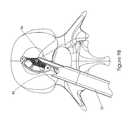
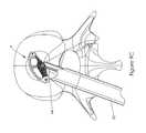
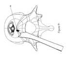
- FIGS. 9A , 9 B, 9 C, 9 D, and 9 Eshow the placement of the insert and the operative relationship of the surgical instrument at various stages of the insertion procedure.
- FIG. 9Fshows an alternative embodiment that utilizes a threaded implant interface.
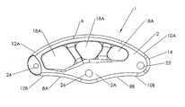
- FIG. 1is a top view of implantable insert 1 .
- Insert 1is generally arcuate in shape and has a top surface 2 and a bottom surface 4 .
- Connecting top surface 2 and bottom surface 4is a convex edge 6 on one side and a pair of concave edges 8 A and 8 B on the second, opposite side.
- the edgeshave first end portions 10 A and 10 B and second end portions 12 A and 12 B.
- a first curved portion 14connects first end portions 10 A and 10 B and a second curved portion 16 connects second end portions 12 A and 12 B.
- Located on the top surface 2is a plurality of apertures 18 A.
- bottom surface 4has a plurality of apertures 18 B.
- Apertures 18 A and 18 Bform a substantially hollow center within the insert 1 .
- the hollow cavity within the insertis used to deliver a bone growth material to fuse the adjacent vertebrae together.
- the insert 1is relatively small in overall size while providing both a large surface for support and a large cavity to provide bone growth material.
- a slotted passageway 20is formed on the second side surfaces including the entire length of concave surface 8 B and a portion of concave surface 8 A. The slot 20 also is continued through first curved portion 14 .
- Insert 1also includes a first cylindrical post 22 extending between, and attached to, the top surface 2 and bottom surface 4 at a first end portion of the insert 1 .
- a second cylindrical post 24extending between, and attached to, the top surface 2 and bottom surface 4 at a second end portion of the insert 1 .
- a third cylindrical post 26is located approximately midway between the first and second post in a location adjacent to the area where concave surfaces 8 A and 8 B approach one another.
- FIG. 2is a side view of insert 1 showing the pair of concave surfaces 8 A and 8 B, first curved portion 14 and second curved portion 16 . Also shown in FIG. 2 is slotted passageway 20 which extends from concave surface 8 A, through concave surface 8 B and continues into first curved portion 14 . Also illustrated in FIG. 2 is a first post 22 and third post 26 .
- FIG. 3is a bottom view of insert 1 showing bottom surface 4 convex surface 6 on the first side and the pair of concave edges 8 A and 8 B on the second side as well as first curved portion 14 and second curved portion 16 . Also illustrated in FIG. 3 are apertures 18 B.
- FIG. 4is a side view of insert 1 that showing the alternative side to that shown in FIG. 2 showing the convex surface 6 on the first side as well top surface 2 , bottom surface 4 , first curved portion 14 and second curved portion 16 . Also shown is in FIG. 4 is a portion of slotted passageway 20 . As can best be seen in FIG. 4 the top surface 2 and bottom surface 4 are generally domed shaped with the high points 4 A and 2 A of each dome being located in the area surrounding the areas where the third cylindrical post 26 connects to the top and bottom surfaces respectively. These high points will form contact points with adjacent vertebrae thereby facilitating pivotal motion of the insert about the third post 26 .
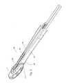
- FIG. 5is a perspective view of insert 1 mounted on surgical instrument 30 prior to implantation.
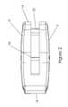
- the instrument 30includes a sleeve 32 and an arm 34 .
- the arm 34is mounted for relative reciprocal longitudinal movement with respect to sleeve 32 .
- the sleeve 32includes a guide rail 36 .
- the guide rail 36presents two tracks formed with one formed on each side of a slot 38 designed to receive arm 34 .
- the arm 34includes profiled surfaces formed on opposite sides of the arm 34 that are configured to operatively engage the tracks formed on the guide rail 36 .
- the sleeve 32also includes a pair of curved surfaces 42 formed on opposite side of sleeve 32 that are shaped to mate with the first curved portion 14 of insert 1 .
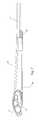
- FIG. 6is a side view of insert 1 attached to surgical instrument 30 .
- concave surfaces 8 A and 8 B of the first sideare shown.
- sleeve 32 , arm 34 , guide rail 36 and a gripping mechanism 40are also shown.
- FIG. 7is a top view of the insert 1 attached to the surgical instrument 30 .
- top surface 2 of the insert 1is shown.
- surgical instrument 30includes sleeve 32 , with mating surface 42 , arm 34 and gripping mechanism 40 .
- FIG. 8is a side view of insert 1 and surgical instrument 30 showing the side opposite to that shown in FIG. 6 .
- Convex surface 6 on insert 1can be seen in this view.
- the sleeve 32 and gripping device 40 of surgical instrument 30are also shown in this view.
- FIGS. 9A through 9Eshow the placement of the insert within the prepared space between the vertebrae and the operative relationship of the surgical instrument and the insert at various stages of the procedure.
- arm 34has a recess 46 that includes an aperture that is cylindrical in cross section. The recess can receive the third post 26 and is capable of retaining or releasing the post dependent upon on direction of the forces applied thereto.
- post 26 on insert 1has been position within recess 46 on arm 34 .
- the first end portion 10 on insert 1is positioned to be in mating relationship with curved mating surfaces 42 located on sleeve 32 .
- the insert 1 as shown in FIG. 9Ais then inserted into the prepared site between adjacent vertebrae.
- instrument 30is then manipulated by gripping device 40 to advance the insert 1 toward a point that would be appropriate for rotation of the insert 1 .
- the sleeve 32is retracted as shown in FIG. 9B and the instrument 30 is moved medially to impart the initial rotation.
- the instrument 30is tamped slightly to impart a small amount of rotation to the insert 1 .
- the sleeve 32is advanced such that a corner portion 44 on the sleeve 32 makes contact with the first end portion of the insert 1 .
- the further advancement of sleeve 32will result in the rotation of insert 1 about the post 26 which is retained in position by arm 34 .
- the sleeve 32is advanced until the insert is rotated into its final position as shown in FIG. 9D . At this point the sleeve 32 is retracted and the mating surfaces 42 are withdrawn from engagement with the first end portion 10 . As shown in FIG. 9E the instrument 30 is then manipulated such that the post 26 is removed from recess 46 and the instrument 30 is then released from the insert 1 . At this point the instrument 30 is removed from the prepared site. Bone growth material is provided in the hollow cavity formed within the insert 1 . Apertures 18 A and 18 b permit bone in growth with the insert 1 and adjacent vertebrae. As an alternative to the recess shown in FIG.
- the arm 34is provided with a threaded implant interface in the form of an externally threaded pin 48 that will threadably engage and disengage from a threaded bore that extends transversally to the longitudinal axis of the post 26 , as shown in FIG. 9F .
Landscapes
- Health & Medical Sciences (AREA)
- Engineering & Computer Science (AREA)
- Biomedical Technology (AREA)
- Orthopedic Medicine & Surgery (AREA)
- Neurology (AREA)
- Transplantation (AREA)
- Oral & Maxillofacial Surgery (AREA)
- Cardiology (AREA)
- Heart & Thoracic Surgery (AREA)
- Vascular Medicine (AREA)
- Life Sciences & Earth Sciences (AREA)
- Animal Behavior & Ethology (AREA)
- General Health & Medical Sciences (AREA)
- Public Health (AREA)
- Veterinary Medicine (AREA)
- Physical Education & Sports Medicine (AREA)
- Prostheses (AREA)
- Surgical Instruments (AREA)
Abstract
Description
Claims (13)
Priority Applications (7)
| Application Number | Priority Date | Filing Date | Title |
|---|---|---|---|
| US12/496,824US8529627B2 (en) | 2009-07-02 | 2009-07-02 | Intervertebral spacer |
| US14/021,482US20140012385A1 (en) | 2009-07-02 | 2013-09-09 | Intervertebral Spacer |
| US14/922,590US9642722B2 (en) | 2009-07-02 | 2015-10-26 | Intervertebral expandable spacer |
| US15/344,932US9788969B2 (en) | 2009-07-02 | 2016-11-07 | Implantable spinal insert |
| US15/346,262US9687360B2 (en) | 2009-07-02 | 2016-11-08 | Implantable spinal insert system |
| US15/479,621US9861497B2 (en) | 2009-07-02 | 2017-04-05 | Intervertebral expandable spacer |
| US15/864,101US10722376B2 (en) | 2009-07-02 | 2018-01-08 | Method of positioning a spinal implant |
Applications Claiming Priority (1)
| Application Number | Priority Date | Filing Date | Title |
|---|---|---|---|
| US12/496,824US8529627B2 (en) | 2009-07-02 | 2009-07-02 | Intervertebral spacer |
Related Child Applications (1)
| Application Number | Title | Priority Date | Filing Date |
|---|---|---|---|
| US14/021,482DivisionUS20140012385A1 (en) | 2009-07-02 | 2013-09-09 | Intervertebral Spacer |
Publications (2)
| Publication Number | Publication Date |
|---|---|
| US20110004314A1 US20110004314A1 (en) | 2011-01-06 |
| US8529627B2true US8529627B2 (en) | 2013-09-10 |
Family
ID=43413093
Family Applications (2)
| Application Number | Title | Priority Date | Filing Date |
|---|---|---|---|
| US12/496,824Active2030-06-30US8529627B2 (en) | 2009-07-02 | 2009-07-02 | Intervertebral spacer |
| US14/021,482AbandonedUS20140012385A1 (en) | 2009-07-02 | 2013-09-09 | Intervertebral Spacer |
Family Applications After (1)
| Application Number | Title | Priority Date | Filing Date |
|---|---|---|---|
| US14/021,482AbandonedUS20140012385A1 (en) | 2009-07-02 | 2013-09-09 | Intervertebral Spacer |
Country Status (1)
| Country | Link |
|---|---|
| US (2) | US8529627B2 (en) |
Cited By (9)
| Publication number | Priority date | Publication date | Assignee | Title |
|---|---|---|---|---|
| US9687360B2 (en) | 2009-07-02 | 2017-06-27 | Atlas Spine, Inc. | Implantable spinal insert system |
| US10179054B2 (en) | 2008-02-06 | 2019-01-15 | Jeffrey B. Kleiner | Spinal fusion cage system with inserter |
| US10195053B2 (en) | 2009-09-18 | 2019-02-05 | Spinal Surgical Strategies, Llc | Bone graft delivery system and method for using same |
| US10201355B2 (en) | 2009-02-06 | 2019-02-12 | Kleiner Intellectual Property, Llc | Angled surgical tool for removing tissue from within an intervertebral space |
| US10245159B1 (en) | 2009-09-18 | 2019-04-02 | Spinal Surgical Strategies, Llc | Bone graft delivery system and method for using same |
| US10624757B2 (en) | 2015-04-09 | 2020-04-21 | Centinel Spine, Llc | Spinal implants configured for tissue sparing angle of insertion and related methods |
| US10973656B2 (en) | 2009-09-18 | 2021-04-13 | Spinal Surgical Strategies, Inc. | Bone graft delivery system and method for using same |
| US11666455B2 (en) | 2009-09-18 | 2023-06-06 | Spinal Surgical Strategies, Inc., A Nevada Corporation | Bone graft delivery devices, systems and kits |
| US12370058B2 (en) | 2022-04-05 | 2025-07-29 | Spine Wave, Inc. | Belt driven expandable interbody fusion device |
Families Citing this family (13)
| Publication number | Priority date | Publication date | Assignee | Title |
|---|---|---|---|---|
| US9265620B2 (en) | 2011-03-18 | 2016-02-23 | Raed M. Ali, M.D., Inc. | Devices and methods for transpedicular stabilization of the spine |
| EP2685921B1 (en) | 2011-03-18 | 2019-03-13 | Raed M. Ali, M.D., Inc. | Transpedicular access to intervertebral spaces and related spinal fusion systems and methods |
| FR2981262B1 (en)* | 2011-10-14 | 2014-09-19 | Pierre Roussouly | INTERSOMATIC IMPLANT |
| US9220607B2 (en) | 2011-10-28 | 2015-12-29 | Warsaw Oorthopedic, Inc. | Pivotable interbody implant system |
| US9861495B2 (en) | 2013-03-14 | 2018-01-09 | Raed M. Ali, M.D., Inc. | Lateral interbody fusion devices, systems and methods |
| US10687962B2 (en) | 2013-03-14 | 2020-06-23 | Raed M. Ali, M.D., Inc. | Interbody fusion devices, systems and methods |
| FR3003159B1 (en)* | 2013-03-14 | 2015-04-03 | Osd Orthopaedic & Spine Dev | RACHIDIAN ANCILLARY AND ITS USE INSTRUCTIONS ENSURING THE INSERTION, POSITIONING AND GUIDING OF AN INTERSOMATIC IMPLANT BY MINI INVASIVE TECHNIQUE |
| US10478313B1 (en) | 2014-01-10 | 2019-11-19 | Nuvasive, Inc. | Spinal fusion implant and related methods |
| WO2017075079A1 (en)* | 2015-10-26 | 2017-05-04 | Atlas Spine, Inc. | Intervertebral expandable spacer |
| FR3063890B1 (en)* | 2017-03-17 | 2022-03-04 | Hassan Razian | SYSTEM FOR POSITIONING AN INSERT BETWEEN TWO BONE PORTIONS |
| US10966843B2 (en)* | 2017-07-18 | 2021-04-06 | DePuy Synthes Products, Inc. | Implant inserters and related methods |
| US11045331B2 (en) | 2017-08-14 | 2021-06-29 | DePuy Synthes Products, Inc. | Intervertebral implant inserters and related methods |
| CN109044571A (en)* | 2018-07-06 | 2018-12-21 | 上海纳米技术及应用国家工程研究中心有限公司 | The preparation method and product of half-moon-shaped 3D printing PLGA/ hydroxyapatite waist Invasive lumbar fusion device and application |
Citations (17)
| Publication number | Priority date | Publication date | Assignee | Title |
|---|---|---|---|---|
| US20030208203A1 (en) | 2002-05-06 | 2003-11-06 | Roy Lim | Minimally invasive instruments and methods for inserting implants |
| US20040117020A1 (en) | 1999-10-21 | 2004-06-17 | George Frey | Devices and techniques for a posterior lateral disc space approach |
| US6863689B2 (en)* | 2001-07-16 | 2005-03-08 | Spinecore, Inc. | Intervertebral spacer having a flexible wire mesh vertebral body contact element |
| US20050065610A1 (en) | 1994-03-18 | 2005-03-24 | Madhavan Pisharodi | Rotating, locking, spring-loaded artificial disk |
| US20050192671A1 (en) | 2002-05-23 | 2005-09-01 | Pioneer Laboratories, Inc. | Artificial disc device |
| US7060073B2 (en) | 1999-10-21 | 2006-06-13 | Sdgi Holdings, Inc. | Devices and techniques for a posterior lateral disc space approach |
| US7235081B2 (en) | 2001-07-16 | 2007-06-26 | Spinecore, Inc. | Wedge plate inserter/impactor and related methods for use in implanting an artificial intervertebral disc |
| US20070225808A1 (en) | 2006-03-22 | 2007-09-27 | Warnick David R | Pivotable interbody spacer |
| US20070225726A1 (en) | 2006-03-23 | 2007-09-27 | Justin Dye | Instruments for delivering spinal implants |
| US20070225812A1 (en) | 2003-10-30 | 2007-09-27 | Gill Steven S | Intervertebral Prosthesis |
| US20080009880A1 (en) | 2006-03-22 | 2008-01-10 | Warnick David R | Pivotable Vetrebral Spacer |
| US20080065082A1 (en) | 2006-09-08 | 2008-03-13 | Narissa Chang | Steerable rasp/trial inserter |
| US20080109005A1 (en) | 2006-08-10 | 2008-05-08 | Trudeau Jeffrey L | System and Methods for Inserting a Spinal Disc Device Into an Intervertebral Space |
| US20080140085A1 (en) | 2006-12-11 | 2008-06-12 | G&L Consulting, Llc | Steerable spine implant insertion device and method |
| US20080221694A1 (en) | 2006-03-22 | 2008-09-11 | Warnick David R | Pivotable Interbody Spacer System and Method |
| US20080287957A1 (en)* | 2007-05-18 | 2008-11-20 | Depuy Spine, Inc. | Insertion blade assembly and method of use |
| US20090048676A1 (en)* | 2005-09-27 | 2009-02-19 | Fabian Jr Henry F | Spine surgery method and motion preserving implant |
- 2009
- 2009-07-02USUS12/496,824patent/US8529627B2/enactiveActive
- 2013
- 2013-09-09USUS14/021,482patent/US20140012385A1/ennot_activeAbandoned
Patent Citations (17)
| Publication number | Priority date | Publication date | Assignee | Title |
|---|---|---|---|---|
| US20050065610A1 (en) | 1994-03-18 | 2005-03-24 | Madhavan Pisharodi | Rotating, locking, spring-loaded artificial disk |
| US20040117020A1 (en) | 1999-10-21 | 2004-06-17 | George Frey | Devices and techniques for a posterior lateral disc space approach |
| US7060073B2 (en) | 1999-10-21 | 2006-06-13 | Sdgi Holdings, Inc. | Devices and techniques for a posterior lateral disc space approach |
| US6863689B2 (en)* | 2001-07-16 | 2005-03-08 | Spinecore, Inc. | Intervertebral spacer having a flexible wire mesh vertebral body contact element |
| US7235081B2 (en) | 2001-07-16 | 2007-06-26 | Spinecore, Inc. | Wedge plate inserter/impactor and related methods for use in implanting an artificial intervertebral disc |
| US20030208203A1 (en) | 2002-05-06 | 2003-11-06 | Roy Lim | Minimally invasive instruments and methods for inserting implants |
| US20050192671A1 (en) | 2002-05-23 | 2005-09-01 | Pioneer Laboratories, Inc. | Artificial disc device |
| US20070225812A1 (en) | 2003-10-30 | 2007-09-27 | Gill Steven S | Intervertebral Prosthesis |
| US20090048676A1 (en)* | 2005-09-27 | 2009-02-19 | Fabian Jr Henry F | Spine surgery method and motion preserving implant |
| US20080221694A1 (en) | 2006-03-22 | 2008-09-11 | Warnick David R | Pivotable Interbody Spacer System and Method |
| US20070225808A1 (en) | 2006-03-22 | 2007-09-27 | Warnick David R | Pivotable interbody spacer |
| US20080009880A1 (en) | 2006-03-22 | 2008-01-10 | Warnick David R | Pivotable Vetrebral Spacer |
| US20070225726A1 (en) | 2006-03-23 | 2007-09-27 | Justin Dye | Instruments for delivering spinal implants |
| US20080109005A1 (en) | 2006-08-10 | 2008-05-08 | Trudeau Jeffrey L | System and Methods for Inserting a Spinal Disc Device Into an Intervertebral Space |
| US20080065082A1 (en) | 2006-09-08 | 2008-03-13 | Narissa Chang | Steerable rasp/trial inserter |
| US20080140085A1 (en) | 2006-12-11 | 2008-06-12 | G&L Consulting, Llc | Steerable spine implant insertion device and method |
| US20080287957A1 (en)* | 2007-05-18 | 2008-11-20 | Depuy Spine, Inc. | Insertion blade assembly and method of use |
Cited By (16)
| Publication number | Priority date | Publication date | Assignee | Title |
|---|---|---|---|---|
| US10179054B2 (en) | 2008-02-06 | 2019-01-15 | Jeffrey B. Kleiner | Spinal fusion cage system with inserter |
| US10201355B2 (en) | 2009-02-06 | 2019-02-12 | Kleiner Intellectual Property, Llc | Angled surgical tool for removing tissue from within an intervertebral space |
| US10722376B2 (en) | 2009-07-02 | 2020-07-28 | Spine Wave, Inc. | Method of positioning a spinal implant |
| US9788969B2 (en) | 2009-07-02 | 2017-10-17 | Atlas Spine, Inc. | Implantable spinal insert |
| US9861497B2 (en) | 2009-07-02 | 2018-01-09 | Atlas Spine, Inc. | Intervertebral expandable spacer |
| US9687360B2 (en) | 2009-07-02 | 2017-06-27 | Atlas Spine, Inc. | Implantable spinal insert system |
| US10195053B2 (en) | 2009-09-18 | 2019-02-05 | Spinal Surgical Strategies, Llc | Bone graft delivery system and method for using same |
| US10245159B1 (en) | 2009-09-18 | 2019-04-02 | Spinal Surgical Strategies, Llc | Bone graft delivery system and method for using same |
| US10973656B2 (en) | 2009-09-18 | 2021-04-13 | Spinal Surgical Strategies, Inc. | Bone graft delivery system and method for using same |
| US11660208B2 (en) | 2009-09-18 | 2023-05-30 | Spinal Surgical Strategies, Inc. | Bone graft delivery system and method for using same |
| US11666455B2 (en) | 2009-09-18 | 2023-06-06 | Spinal Surgical Strategies, Inc., A Nevada Corporation | Bone graft delivery devices, systems and kits |
| US12053393B2 (en) | 2009-09-18 | 2024-08-06 | Spinal Surgical Strategies, Inc. | Bone graft delivery system and method for use |
| US12167971B2 (en) | 2009-09-18 | 2024-12-17 | Spinal Surgical Strategies, Inc. | Bone graft delivery devices, systems and kits |
| US10624757B2 (en) | 2015-04-09 | 2020-04-21 | Centinel Spine, Llc | Spinal implants configured for tissue sparing angle of insertion and related methods |
| US11517445B2 (en) | 2015-04-09 | 2022-12-06 | Centinel Spine, Llc | Spinal implants configured for tissue sparing angle of insertion and related methods |
| US12370058B2 (en) | 2022-04-05 | 2025-07-29 | Spine Wave, Inc. | Belt driven expandable interbody fusion device |
Also Published As
| Publication number | Publication date |
|---|---|
| US20140012385A1 (en) | 2014-01-09 |
| US20110004314A1 (en) | 2011-01-06 |
Similar Documents
| Publication | Publication Date | Title |
|---|---|---|
| US8529627B2 (en) | Intervertebral spacer | |
| US10722376B2 (en) | Method of positioning a spinal implant | |
| US7988695B2 (en) | Articulated delivery instrument | |
| US7951153B2 (en) | Devices and methods for inter-vertebral orthopedic device placement | |
| US9737412B2 (en) | Intervertebral implant having extendable bone fixation members | |
| KR101358560B1 (en) | Transforaminal intersomatic cage and an instrument for implanting the cage | |
| JP4758912B2 (en) | Method and instrument for inserting an intervertebral graft and device | |
| JP5584223B2 (en) | Surgical instrument for inserting an implant between two bones and method of use | |
| JP4580986B2 (en) | Method and apparatus for inserting an intervertebral disc prosthesis | |
| US20220110765A1 (en) | Devices and methods for spinal implantation | |
| US8753394B2 (en) | Minimally invasive apparatus to manipulate and revitalize spinal column disc | |
| US20080065082A1 (en) | Steerable rasp/trial inserter | |
| US10709568B2 (en) | Intervertebral body spacer assembly and kit | |
| JP2020203099A (en) | Minimally disruptive retractor and associated methods for spinal surgery | |
| JP2010508911A (en) | Apparatus and method for providing surgical access to the spine | |
| JP2007521886A (en) | System and method for spinal surgery | |
| WO2017075079A1 (en) | Intervertebral expandable spacer | |
| US12414858B2 (en) | Curved expandable interbody devices and deployment tools |
Legal Events
| Date | Code | Title | Description |
|---|---|---|---|
| AS | Assignment | Owner name:ATLAS SPINE, INC., FLORIDA Free format text:ASSIGNMENT OF ASSIGNORS INTEREST;ASSIGNOR:BAYNHAM, MATTHEW G.;REEL/FRAME:022907/0535 Effective date:20090626 | |
| STCF | Information on status: patent grant | Free format text:PATENTED CASE | |
| AS | Assignment | Owner name:SPINE WAVE, INC., CONNECTICUT Free format text:LICENSE;ASSIGNOR:ATLAS SPINE, INC.;REEL/FRAME:037825/0710 Effective date:20160223 | |
| FPAY | Fee payment | Year of fee payment:4 | |
| AS | Assignment | Owner name:OXFORD FINANCE LLC, VIRGINIA Free format text:SECURITY INTEREST;ASSIGNOR:SPINE WAVE, INC.;REEL/FRAME:046612/0765 Effective date:20180719 Owner name:SILICON VALLEY BANK, MASSACHUSETTS Free format text:SECURITY INTEREST;ASSIGNOR:SPINE WAVE, INC.;REEL/FRAME:046612/0765 Effective date:20180719 | |
| MAFP | Maintenance fee payment | Free format text:PAYMENT OF MAINTENANCE FEE, 8TH YR, SMALL ENTITY (ORIGINAL EVENT CODE: M2552); ENTITY STATUS OF PATENT OWNER: SMALL ENTITY Year of fee payment:8 | |
| MAFP | Maintenance fee payment | Free format text:PAYMENT OF MAINTENANCE FEE, 12TH YR, SMALL ENTITY (ORIGINAL EVENT CODE: M2553); ENTITY STATUS OF PATENT OWNER: SMALL ENTITY Year of fee payment:12 |