US8528793B2 - Actuator - Google Patents
ActuatorDownload PDFInfo
- Publication number
- US8528793B2 US8528793B2US12/978,695US97869510AUS8528793B2US 8528793 B2US8528793 B2US 8528793B2US 97869510 AUS97869510 AUS 97869510AUS 8528793 B2US8528793 B2US 8528793B2
- Authority
- US
- United States
- Prior art keywords
- rod
- cam
- actuator
- catch
- engaging
- Prior art date
- Legal status (The legal status is an assumption and is not a legal conclusion. Google has not performed a legal analysis and makes no representation as to the accuracy of the status listed.)
- Expired - Fee Related, expires
Links
Images


Classifications
- B—PERFORMING OPERATIONS; TRANSPORTING
- B05—SPRAYING OR ATOMISING IN GENERAL; APPLYING FLUENT MATERIALS TO SURFACES, IN GENERAL
- B05C—APPARATUS FOR APPLYING FLUENT MATERIALS TO SURFACES, IN GENERAL
- B05C17/00—Hand tools or apparatus using hand held tools, for applying liquids or other fluent materials to, for spreading applied liquids or other fluent materials on, or for partially removing applied liquids or other fluent materials from, surfaces
- B05C17/005—Hand tools or apparatus using hand held tools, for applying liquids or other fluent materials to, for spreading applied liquids or other fluent materials on, or for partially removing applied liquids or other fluent materials from, surfaces for discharging material from a reservoir or container located in or on the hand tool through an outlet orifice by pressure without using surface contacting members like pads or brushes
- B05C17/01—Hand tools or apparatus using hand held tools, for applying liquids or other fluent materials to, for spreading applied liquids or other fluent materials on, or for partially removing applied liquids or other fluent materials from, surfaces for discharging material from a reservoir or container located in or on the hand tool through an outlet orifice by pressure without using surface contacting members like pads or brushes with manually mechanically or electrically actuated piston or the like
- B05C17/0116—Hand tools or apparatus using hand held tools, for applying liquids or other fluent materials to, for spreading applied liquids or other fluent materials on, or for partially removing applied liquids or other fluent materials from, surfaces for discharging material from a reservoir or container located in or on the hand tool through an outlet orifice by pressure without using surface contacting members like pads or brushes with manually mechanically or electrically actuated piston or the like characterised by the piston driving means
- B05C17/012—Stepwise advancing mechanism, e.g. pawl and ratchets
- B05C17/0123—Lever actuated
- B05C17/0126—Lever actuated comprising an element, e.g. an arc compensating element, articulated at one end on the lever and at the other end on the piston rod driving means, e.g. a pawl
- A—HUMAN NECESSITIES
- A61—MEDICAL OR VETERINARY SCIENCE; HYGIENE
- A61C—DENTISTRY; APPARATUS OR METHODS FOR ORAL OR DENTAL HYGIENE
- A61C5/00—Filling or capping teeth
- A61C5/60—Devices specially adapted for pressing or mixing capping or filling materials, e.g. amalgam presses
- A61C5/62—Applicators, e.g. syringes or guns
- B—PERFORMING OPERATIONS; TRANSPORTING
- B05—SPRAYING OR ATOMISING IN GENERAL; APPLYING FLUENT MATERIALS TO SURFACES, IN GENERAL
- B05B—SPRAYING APPARATUS; ATOMISING APPARATUS; NOZZLES
- B05B15/00—Details of spraying plant or spraying apparatus not otherwise provided for; Accessories
- B05B15/50—Arrangements for cleaning; Arrangements for preventing deposits, drying-out or blockage; Arrangements for detecting improper discharge caused by the presence of foreign matter
- B05B15/52—Arrangements for cleaning; Arrangements for preventing deposits, drying-out or blockage; Arrangements for detecting improper discharge caused by the presence of foreign matter for removal of clogging particles
- B05B15/522—Arrangements for cleaning; Arrangements for preventing deposits, drying-out or blockage; Arrangements for detecting improper discharge caused by the presence of foreign matter for removal of clogging particles using cleaning elements penetrating the discharge openings
- B05B15/5223—Arrangements for cleaning; Arrangements for preventing deposits, drying-out or blockage; Arrangements for detecting improper discharge caused by the presence of foreign matter for removal of clogging particles using cleaning elements penetrating the discharge openings the cleaning element, e.g. a needle, and the discharge opening being movable relative to each other in a direction substantially parallel to the flow of liquid or other fluent material through said opening
- B05B15/5225—Arrangements for cleaning; Arrangements for preventing deposits, drying-out or blockage; Arrangements for detecting improper discharge caused by the presence of foreign matter for removal of clogging particles using cleaning elements penetrating the discharge openings the cleaning element, e.g. a needle, and the discharge opening being movable relative to each other in a direction substantially parallel to the flow of liquid or other fluent material through said opening the cleaning element being located upstream of the discharge opening or being actuated upstream therefrom
- Y—GENERAL TAGGING OF NEW TECHNOLOGICAL DEVELOPMENTS; GENERAL TAGGING OF CROSS-SECTIONAL TECHNOLOGIES SPANNING OVER SEVERAL SECTIONS OF THE IPC; TECHNICAL SUBJECTS COVERED BY FORMER USPC CROSS-REFERENCE ART COLLECTIONS [XRACs] AND DIGESTS
- Y10—TECHNICAL SUBJECTS COVERED BY FORMER USPC
- Y10T—TECHNICAL SUBJECTS COVERED BY FORMER US CLASSIFICATION
- Y10T74/00—Machine element or mechanism
- Y10T74/18—Mechanical movements
- Y10T74/18056—Rotary to or from reciprocating or oscillating
- Y10T74/1828—Cam, lever, and slide
Definitions
- the present inventionrelates to an actuator for advancing a rod and, in particular, a dispenser or applicator using such an actuator to apply a dispensing pressure to a viscous material. More particularly, the present invention relates to such a dispenser or applicator for dentistry applications.
- Viscous materialsuch as mastic caulking material
- a cartridge having a discharge nozzlecan be mounted in a dispensing appliance, often called a dispensing gun or applicator.
- a dispensing gunAn example of such a dispensing gun is described in British patent GB1555455.
- the gunhas a plunger or a push rod slideably mounted in a cartridge.
- the cartridgeis mounted in a keep before the plunger.
- the plungeris advanced by means of a catch plate linked to a trigger lever engaging the rod.
- a dispensing forceis applied to the trigger lever, the plunger forces a piston, inside one end of the cartridge, forward to urge the material from the nozzle at the other end.
- the trigger and catch plateare reset at the end of a dispensing stroke and the dispensing force can be reapplied.
- the plungeris held against the piston by means of a locking plate.
- a forceis applied to the locking plate to disengage the locking plate from the rod and allow retreat of the rod.
- the locking platecan be arranged to either substantially prevent any retreat of the rod during dispensing or to allow a small amount of retreat of the rod to release pressure applied to the cartridge, as disclosed, for example, in European patent EP0448375.
- the locking plateIn order to be able to retreat the plunger, the locking plate must be accessible so that a releasing force can be applied to it, either directly or by an intermediate mechanical linkage where the locking plate is within a housing together with the remaining actuating mechanism, for example as disclosed in U.S. Pat. No. 5,370,282.
- the inventorshave realized that, for a number of reasons, it may be undesirable to require access to the locking plate or a corresponding release lever or button in order to release the locking plate to allow retreat of the rod.
- the locking plate or leveris arranged such that it can be actuated by the thumb of a user's hand holding the gun to leave the other hand free to retreat the rod, this will compromise the design freedom in designing the gun, in particular for dispensing guns of overall small size.
- the need for an external locking plate or levertends to make the dispensing gun more difficult to clean, even if the remaining actuating mechanism is enclosed in a housing.
- an actuator for advancing a rodcomprising a catch member for engaging the rod, a trigger member for moving the catch member to advance the rod in one direction and a locking member for engaging the rod to prevent the rod retreating in the other direction.
- the actuatorfurther comprises a release arrangement for transforming a torque applied to the rod into a releasing force disengaging the locking member to enable retreat of the rod in the other direction.
- the release arrangementenables the release of the locking member by rotation of the rod, thereby dispensing with the need for a locking plate (or corresponding lever) which is separately actuatable by user.
- Rotation of the rodthus urges the locking member away from a configuration in which it is engaged with (bites on) the rod, preventing the rod's retreat, to disengage the locking member from the rod.
- the usercan release and retreat the rod with a single hand gesture, thereby addressing the problems discussed above and increasing ease of use of the actuator generally.
- the release arrangementcomprises a cam member and a cam follower.
- the cam memberslidingly accepts the rod and defines a cam at one end.
- the camengages the cam follower to transfer rotation of the rod to translation of the cam follower, thereby applying the releasing force to the locking member.
- the release arrangementis arranged to transform the torque applied to the rod to a releasing force disengaging the catch member, as well as the locking member, to enable retreat of the rod.
- the locking member and/or catch memberare biased into an engaged attitude with respect to the rod and the releasing force causes rotation of the locking and/or catch member away from the engaged attitude.
- the locking memberis forward of the catch member in the one direction. This enables a space efficient arrangement of the actuator in a confined housing, making use of the space forward of the catch member to accommodate the locking member.
- the actuatorprovides end of stroke release, releasing the catch member when the rod reaches a predetermined (usually fully advanced) position to prevent further pressure being applied to the rod and the corresponding risk of damaging the actuator and/or dispenser or dispensing cartridge to which the actuator is applied.
- the actuatorcomprises a holding member for holding the catch member in a disengaged relationship with respect to the rod when the rod is advanced to the predetermined position. At this point, further actuation of the trigger member does not advance the rod any further.
- the rodcomprises a protrusion, for example a pin extending on one or both sides of the rod, for engaging the holding member and thus to advance the holding member with the rod as the rod advances to a predetermined position.
- the cam memberdefines a channel in which this protrusion is slideably accepted to cause the cam member to rotate with the rod.
- the holding memberis a sleeve disposed between the rod and the cam member, resulting in a compact arrangement in which the rod is supported by the sleeve and cam member to provide a journal close to the actuating mechanism and, in particular, the catch member.
- the rodincludes a protrusion, for example as described above, and the cam member defines a channel slideably accepting this protrusion to cause the cam member to rotate with the rod.
- a dispenser for dispensing a viscous materialcomprising an actuator as described above for applying a dispensing pressure to the viscous material.
- the dispenserfully encloses the catch member, locking member and release arrangement.
- the dispenseris, in some embodiments, arranged for use in dentistry.
- a dispenser for dispensing a viscous materialcomprising an actuator for advancing a rod to apply a dispensing pressure to the viscous material.
- the dispensercomprises a window through which the advance of the rod can be observed.
- the windowcomprises graduations indicating the amount of advance of the rod as a result of a complete actuation of the trigger member.
- the featureis a shoulder between portions of the rod having different diameters.
- an actuator for advancing a rodcomprising means for advancing the rod in response to actuation of a trigger lever and means for preventing retreat of the rod.
- the actuatorfurther comprises means for releasing the rod in response to rotation of the rod in order to enable retreat of the rod.
- FIG. 1is a perspective view of a dispenser in accordance with an embodiment of the invention
- FIG. 2is a top elevation view of the dispenser
- FIG. 3is a side elevation view of the dispenser
- FIG. 4is a view exposing an actuating mechanism inside the dispenser
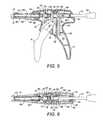
- FIG. 5depicts a partial cross-section along the line A-A of FIG. 2 ;
- FIG. 6depicts a partial cross-sectional view along the line B-B in FIG. 3 ;
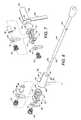
- FIG. 7is an exploded view of components of an actuating mechanism for advancing a rod of the dispenser.
- FIG. 8is another exploded view of components of the actuating mechanism, including the rod.
- a dispenser or applicatorcomprises an actuator 2 and a cartridge holder 4 .
- the actuator 2comprises a stock 6 and a trigger lever 8 movable relative to the stock 6 .
- a rod 10is disposed slideably within the stock 6 and a mechanism inside the stock 6 , described in detail below, is arranged such that actuation of the trigger lever 8 causes the rod 10 to advance with respect to the stock 6 and the cartridge holder 4 into a cartridge (not shown) held in a slot 12 of the cartridge holder 4 .
- a positioning member 14is biased by a disc spring (non shown) to protrude into the slot 12 , thereby applying a resilient positioning force to a rear end of the cartridge held in the slot 12 .
- the cartridge holder 4comprises a window 16 through which the advance of the rod 10 can be observed.
- the rod 10carries a knob 18 for enabling a user of the dispenser to rotate the rod 10 in order to release the mechanism inside the stock 6 such that the rod 10 can be retreated, for example to change a cartridge once the rod 10 has been advanced into it.
- a driving mechanism of the actuator 2comprises the trigger lever 8 being pivotably secured to the stock 6 by pivot 20 .
- a lower portion 22 of the trigger lever 8is configured for actuation by a user's fingers pulling the trigger lever 8 towards the stock 6 and an upper portion 24 opposed to the lower portion 22 across the pivot 20 comprises a trigger pin 26 for engaging a catch plate 28 .
- the trigger lever 8is biased into a rest orientation with the lower portion 22 disposed away from the stock 6 by a torsion spring 29 .
- the catch plate 28has an aperture 30 accepting the rod 10 and is biased against the trigger pin 26 and into engagement with the rod 10 by a first helical spring 32 disposed forward of the catch plate 28 towards the cartridge holder 4 and resting against a forked cross member 34 providing a seat for the first helical spring 32 .
- the forked cross-member 34accepts the rod 10 between its prongs extending across the interior space inside the stock and locating between support struts 36 at their free ends.
- a locking plate 38has an aperture 40 accepting the rod 10 and is disposed forward of the catch plate 28 and the forked cross member 34 .
- a second helical spring 42rests against a rear end of the cartridge holder 4 providing a seat for the second helical spring 42 .
- the second helical spring 42biases the locking plate 38 against a cross bar 44 rearwards of the locking plate 38 and thereby into engagement with the rod 10 .
- the arrangement of the catch plate 28 and locking plate 38means that they bite on the rod when the rod is pulled rearwards relative to the catch and locking plates 28 , 38 but allow the rod to be pushed forward. Consequently, the catch plate 28 bites on the rod 10 when the trigger lever 8 is pulled towards the stock 6 , advancing the rod, and slides across the rod as the trigger lever 8 returns to its rest position away from the stock 6 , while the rod 10 is held in position by the locking plate 38 biting on it.
- repeated actuation of the trigger lever 6 towards the stock 6advances the rod 10 in a forward direction towards the slot 12 with each stroke of the trigger lever 8 .
- a cam member 46comprises a sleeve 48 accepting the rod 10 and defines channels 50 accepting protruding portions of a pin 52 disposed in a hole through the rod 10 .
- An interior forward wall of the channels 50limits the advance of the pin 52 in the channels 50 and hence advance at the rod 10 .
- a stop 54extending from an interior wall of the stock 6 limits the retreat of the rod 10 in the other direction.
- the cam member 46defines a flange 56 abutting an interior wall 58 of the stock 6 .
- the interior wall 58defines an aperture 60 rotatably accepting a front end 62 of the cam member 46 .
- a leaf spring 64extends from the cam member 46 in a direction perpendicular to the direction of the pin 52 between the channels 50 , the cam member 46 and the leaf spring 64 being molded in one piece.
- the leaf spring 64is held in an aperture 66 of a strut wall 68 of the stock 6 and defines a rest orientation for the cam member 46 in which the pin 52 and channels 50 extend substantially perpendicularly on either side of a mid plane of the stock 6 .
- Cams 70extend forward from the end 62 on either side of the rod 10 , aligned with the direction of the leaf spring 64 .
- a cam follower 72is disposed generally around the rod 10 forward of the cam member 46 and comprises a first portion 74 disposed between the cam member 46 and the catch plate 28 linked to a second portion 76 by a linking portion 78 .
- the second portionis disposed between the forked cross member 34 and the locking plate 38 .
- the linking portions 78extend between the first and second portions 74 , 76 on either side of the rod 10 and the catch plate 28 and first helical spring 32 around it and between the prongs of the forked cross member 34 . Further, the linking portion 78 extends forward of the second portion 76 on either side of the locking plate 38 .
- a cam engaging surface 80 of the first portion 74face the cams 70 and is shaped to have troughs aligned with the cams 70 in the rest orientation of the cam member 46 and lobes to the sides of the troughs aligned perpendicularly to a direction defined by the cams 70 in the rest orientation. In this orientation, the cam member 46 and cam follower 72 are disposed relative to each other such that the cams 70 are disposed inside the troughs and between the lobes of the cam engaging surface 80 .
- the cam member 46is constrained for only rotational movement relative to the stock 6 by virtue of being disposed in the aperture 60 with movement along the direction of the rod being prevented by the flange 56 engaging the wall 58 and a rear end 82 of the cam member 46 engaging the stop 54 . Excessive rotation of the rod 10 and cam member 46 is prevented by a nub (not shown) protruding from an interior surface of the stock 6 locating inside a recessed portion 84 of the flange 56 , thus limiting the rotational range to the angular extent of the recessed portion 84 of the flange 56 .
- both the catch plate 28 and locking plate 38prevent retreat of the rod 10 .
- a usercan disengage the catch plate 28 and locking plate 38 by rotating the rod 10 by means of the knob 18 .
- the rotation of the rod 10is transferred to the cam member 46 by the pin 52 .
- the cams 70engage the lobes between the troughs of the cam engaging surface 80 , urging the cam follower 72 away from the cam member 46 , the interaction between the cams 70 and cam engaging surface 80 thus causes the cam follower 72 to move longitudinally forward along the rod 10 to engage the catch plate 28 and locking plate 38 with, respectively, the first portion 74 and second portion 76 , causing the catch plate 28 and locking plate 38 to rotate away from their respective engaged attitudes with respect to the rod 10 in which they bite on the rod 10 until the catch plate 28 and locking plate 38 are held between the respective helical spring and portion of the cam follower 72 in a disengaged attitude relative to the rod 10 so that the rod can slide freely allowing the rod 10 to be retreated.
- a bushing 86is disposed around the rod 10 and the cam is slidingly accepted by member 46 and the first portion 74 of the cam follower 72 .
- a lip 88prevents the bushing 86 from sliding the rearwards past the first portion 74 .
- the length of the bushingis selected such that the pin 52 engages a rear aspect of the bushing 86 as the rod 10 approaches the end of its forward travel and takes the bushing 86 with it on the last stroke of the trigger lever 6 , holding the catch plate 28 in a disengaged attitude relative to the rod 10 between the first helical spring 32 and the lip 88 at or close to the position of the trigger pin 26 when the trigger lever 6 is fully depressed.
- the cartridge carrier 4comprises an outer portion 90 and an insert 92 , acting as a bushing for the rod 10 .
- the rod 10comprises a first portion 94 which is of a larger diameter than a second portion 96 , defining a shoulder 98 between the two portions.
- the first portion 94is engaged by the catch plate 28 and the locking plate 38 and the second portion 96 acts as a plunger advanceable into a cartridge held in the slot 12 .
- the first portion 94is journaled by the insert 92 adjacent to the locking plate 38 and by the bushing 86 adjacent to the catch plate 28 .
- the window 16 described aboveextends through the outer portion 90 and insert 92 so that the rod 10 is visible.
- the window 16has graduations 100 corresponding to the position of the shoulder 98 at the end of each stroke between the rod's 10 fully advanced and fully retreated positions.
- graduations 100provide a measure of the amount of material remaining which can be dispensed with the dispenser.
- Most components of the above described dispenserare molded from suitable plastic materials, for example glass filled Nylon, polycarbonate (PC), polyethersulfate (PES), ABS.
- suitable plastic materialsfor example glass filled Nylon, polycarbonate (PC), polyethersulfate (PES), ABS.
- the knob 18the cartridge holder 16 outer portion 90 and insert 92 , the positioning member 14 the cam follower 72 , the cam member 46 , the trigger lever 8 and two halves of the stock 6 .
- the cartridge holder 4is held relative to the slot by flanges engaging corresponding slots in the stock and the two halves of the stock are ultrasonically welded together although other securing methods, such as adhesive bonding, can equally be applied.
- the remaining componentsare made of suitable metal materials, for example stainless steel.
- plastic materials that can be sterilized in an autoclaveare employed, such as PES or PC and stainless steel is used for all non-plastic parts.
- the catch platemay not be engaged with the rod 10 in the rest configuration of the trigger lever 6 , with no dispensing force applied to the trigger lever 6 , but rather rest in a disengaged attitude from the rod 10 against an abutment or other feature of the stock 6 , so that the cam follower 72 only needs to release the locking plate 38 in order to enable retreat of the rod 10 . It is generally possible to reverse the order of the catch plate 28 and locking plate 38 and in embodiments where the catch plate 28 is not engaged with the rod 10 in the trigger lever's 8 rest configuration, this enables the cam follower 72 to be simplified so that only a single portion carrying the cam engaging surface 80 and arranged to disengage the locking plate 38 is necessary.
- the bushing 86may be omitted from some embodiments, with a corresponding reduction in the aperture of the cam member 46 and/or cam follower 72 being possible to ensure secure journaling of the rod 10 .
- the cam membermay have only a single cam, omitting one of the cams of the specific embodiment described above.
- a cam or camsare directly attached to an arm or arms extending away from the rod in a suitable orientation to directly interact with the catch and/or locking plate to nudge them into a disengaged position in response to rotation of the rod.
- a cam or cams directly nudging the locking and/or catch platecan be mounted on a gear or cog wheel directly or indirectly driven by rotation of the rod. Numerous other arrangements are equally possible.
Landscapes
- Health & Medical Sciences (AREA)
- Oral & Maxillofacial Surgery (AREA)
- Dentistry (AREA)
- Epidemiology (AREA)
- Life Sciences & Earth Sciences (AREA)
- Animal Behavior & Ethology (AREA)
- General Health & Medical Sciences (AREA)
- Public Health (AREA)
- Veterinary Medicine (AREA)
- Engineering & Computer Science (AREA)
- Mechanical Engineering (AREA)
- Dental Tools And Instruments Or Auxiliary Dental Instruments (AREA)
Abstract
Description
Claims (15)
Applications Claiming Priority (3)
| Application Number | Priority Date | Filing Date | Title |
|---|---|---|---|
| EP10196813 | 2010-12-23 | ||
| EP10196813.9 | 2010-12-23 | ||
| EP10196813AEP2468417A1 (en) | 2010-12-23 | 2010-12-23 | Actuator for a cartridge dispenser |
Publications (2)
| Publication Number | Publication Date |
|---|---|
| US20120160877A1 US20120160877A1 (en) | 2012-06-28 |
| US8528793B2true US8528793B2 (en) | 2013-09-10 |
Family
ID=44121752
Family Applications (1)
| Application Number | Title | Priority Date | Filing Date |
|---|---|---|---|
| US12/978,695Expired - Fee RelatedUS8528793B2 (en) | 2010-12-23 | 2010-12-27 | Actuator |
Country Status (2)
| Country | Link |
|---|---|
| US (1) | US8528793B2 (en) |
| EP (1) | EP2468417A1 (en) |
Cited By (2)
| Publication number | Priority date | Publication date | Assignee | Title |
|---|---|---|---|---|
| US9914148B2 (en) | 2014-07-15 | 2018-03-13 | Sulzer Mixpac Ag | Multicomponent dispenser |
| US10814347B2 (en)* | 2018-06-07 | 2020-10-27 | Zhejiang Volcano Machinery Co., Ltd. | Caulking gun |
Families Citing this family (10)
| Publication number | Priority date | Publication date | Assignee | Title |
|---|---|---|---|---|
| GB0918585D0 (en)* | 2009-10-22 | 2009-12-09 | Cox Ltd | Plunger |
| ES2565054T3 (en) | 2010-12-23 | 2016-03-31 | P C Cox Limited | Pneumatic dispenser |
| EP2468418B1 (en) | 2010-12-23 | 2013-06-19 | P C Cox Limited | Valve and dispenser using the valve |
| PT2468419E (en) | 2010-12-23 | 2015-05-13 | Cox Ltd | Bi-directional pneumatic dispenser |
| US9723845B2 (en)* | 2014-12-12 | 2017-08-08 | Helen Of Troy Limited | Dispensing gun |
| US20180290080A1 (en)* | 2017-04-07 | 2018-10-11 | Tokitae Llc | Device to provide even pressure for filtration of biological sample |
| CN115605296A (en)* | 2020-06-03 | 2023-01-13 | 迈德米斯瑞士股份公司(Ch) | Dispenser |
| TWI783825B (en)* | 2021-12-14 | 2022-11-11 | 凱馴企業有限公司 | Glue gun with inner shell seat |
| EP4478981A1 (en)* | 2022-04-28 | 2024-12-25 | medmix Switzerland AG | Multi-use dispenser and application set with such a multi-use dispenser and at least one applicator |
| EP4268760A1 (en)* | 2022-04-28 | 2023-11-01 | medmix Switzerland AG | Multi-use dispenser and application set with such a multi-use dispenser and at least one applicator |
Citations (84)
| Publication number | Priority date | Publication date | Assignee | Title |
|---|---|---|---|---|
| US2388662A (en) | 1941-12-09 | 1945-11-13 | Western Electric Co | Liquid measuring apparatus |
| FR984352A (en) | 1949-04-08 | 1951-07-05 | Approvisionnement General Pour | Dosing gun for dispensing liquids, emulsions and suspensions |
| US2582156A (en) | 1948-03-20 | 1952-01-08 | Wilbur P Peterson | Dispensing apparatus and cartridge therefor |
| US2692706A (en) | 1950-07-27 | 1954-10-26 | Wiksten Carl Jay | Air pressure caulking gun |
| US2705463A (en) | 1954-04-21 | 1955-04-05 | William V Moore | Pastry decorator |
| GB793277A (en) | 1955-01-14 | 1958-04-16 | Jules Maillard | Improvements in and relating to an apparatus for delivering different materials in predetermined proportions |
| CH329614A (en) | 1955-06-03 | 1958-04-30 | Maillard Jules | Apparatus for mixing specific proportions of materials |
| US2840276A (en) | 1955-10-28 | 1958-06-24 | Jr William A Dreyer | Feeding device |
| US2839945A (en)* | 1957-02-13 | 1958-06-24 | Zion Benson | Control device |
| US3254806A (en) | 1963-05-30 | 1966-06-07 | Madsen Niels Kirstein | Power driven putty gun |
| NL6602366A (en) | 1965-02-25 | 1966-08-26 | ||
| US3353537A (en) | 1965-08-11 | 1967-11-21 | George W Knox | Automatic multi-dosage inoculating instrument |
| US3431953A (en) | 1966-05-25 | 1969-03-11 | Russell G Rutherford | Measured liquid dispenser |
| US3559687A (en) | 1968-04-01 | 1971-02-02 | Alkon Products Corp | Fluid valve construction |
| DE1784336A1 (en) | 1968-07-29 | 1971-08-19 | Helmut Roos | Spray gun for grouting and filling precast elements and other areas and joints |
| US3740612A (en) | 1971-05-28 | 1973-06-19 | Champion Spark Plug Co | Apparatus for coating with electrostatically charged particulate materials |
| US3768472A (en) | 1972-02-07 | 1973-10-30 | M Hodosh | Fluid dispensing gun |
| US3780384A (en) | 1972-01-17 | 1973-12-25 | G Rivelle | Automatic toilet flushing system |
| US3819115A (en) | 1972-03-13 | 1974-06-25 | Atlas Copco Ab | Electrostatic spray gun |
| US3980209A (en) | 1973-12-10 | 1976-09-14 | Roean Industries | Bulk loading plastic compound dispensing device |
| US4029236A (en) | 1976-05-17 | 1977-06-14 | Colgate-Palmolive Company | Two product dispenser with cooperating telescoping cylinders |
| US4116364A (en) | 1976-02-02 | 1978-09-26 | Binks Manufacturing Company | Dispensing system for low stability fluids |
| US4171072A (en)* | 1978-02-08 | 1979-10-16 | Geo B. Davis, Jr. | Hand held electric caulking gun |
| GB1555455A (en) | 1976-06-11 | 1979-11-07 | Cox Mastic Appliances Ltd P C | Dispensing gun |
| US4174068A (en) | 1978-11-07 | 1979-11-13 | Rudolph Robert L | Gun having disposable cartridge |
| US4264021A (en)* | 1978-02-08 | 1981-04-28 | Davis George B Jun | Hand held electric caulking gun |
| GB1589381A (en) | 1977-07-18 | 1981-05-13 | Cox Newbury Ltd | Pneumatic dispensers for viscous materials |
| US4273269A (en)* | 1978-02-08 | 1981-06-16 | Davis George B Jun | Hand held electric caulking gun |
| US4290091A (en) | 1976-12-27 | 1981-09-15 | Speeflo Manufacturing Corporation | Spray gun having self-contained low voltage and high voltage power supplies |
| US4322022A (en)* | 1980-03-19 | 1982-03-30 | Whirlco, Inc. | Quick release for helically-threaded drive unit |
| DE3031939A1 (en) | 1980-08-25 | 1982-04-01 | Hilti AG, 9494 Schaan | Press-out device for flowable goods in containers - includes piston rod movable by actuator with free end of rod flexible and capable of being turned by 180 degrees |
| US4366919A (en) | 1978-05-01 | 1983-01-04 | Coaxial Cartridges, Inc. | Composite cartridge and device for metering extrusion of contents |
| US4376498A (en) | 1980-10-02 | 1983-03-15 | Davis George B Jun | Hand-held pneumatic caulking gun |
| US4472141A (en) | 1981-10-26 | 1984-09-18 | Dragan William B | All purpose dental syringe |
| DE3420324A1 (en) | 1984-05-30 | 1985-12-05 | Lechler Chemie Gmbh, 7000 Stuttgart | Dispensing device for a plurality of flowable material components |
| US4757628A (en)* | 1987-03-27 | 1988-07-19 | Bulfer Gary M | Shark saber |
| EP0276665A2 (en) | 1987-01-26 | 1988-08-03 | Wilhelm A. Keller | Pressure-activated dispenser for operaing twin cartridges |
| DE9000957U1 (en) | 1990-01-29 | 1990-04-05 | Deutsche Tecalemit Gmbh, 4800 Bielefeld | Pneumatically operated multi-purpose gun for applying pasty materials |
| DE9011965U1 (en) | 1990-08-17 | 1990-10-18 | Deutsche Tecalemit Gmbh, 4800 Bielefeld | Compressed air controlled and operated multi-purpose gun for applying pasty materials |
| EP0406113A2 (en) | 1989-06-30 | 1991-01-02 | Illinois Tool Works Inc. | Dosage control for adhesive dispenser |
| EP0436155A2 (en) | 1990-01-05 | 1991-07-10 | Maderag Ag | Extrusion gun for double-wall cartridges |
| EP0443611A2 (en) | 1990-02-23 | 1991-08-28 | STANDARD PNEUMATIC & ELECTRIC TOOL COMPANY, A DIVISION OF THE HAMILTON COMPANY, INC. | Dual component dispenser gun |
| EP0448375A2 (en) | 1990-03-22 | 1991-09-25 | Bba Group Plc. | Dispensing gun |
| US5125836A (en)* | 1991-02-04 | 1992-06-30 | Centrix, Inc. | Easy loading manual extruder for viscous material |
| US5127552A (en) | 1989-08-24 | 1992-07-07 | Dow Corning Corporation | Foam mixer-applicator with foaming chamber and method of using |
| USD329277S (en) | 1989-12-14 | 1992-09-08 | Keske David G | Urethane foam gun |
| US5163584A (en) | 1990-12-18 | 1992-11-17 | Polyfoam Products, Inc. | Method and apparatus for mixing and dispensing foam with injected low pressure gas |
| EP0525562A1 (en) | 1991-07-29 | 1993-02-03 | OFFICINE MECCANICHE A.N.I. S.p.A. | Device for dispensing fluid and/or semi-fluid products |
| EP0551998A1 (en) | 1992-01-14 | 1993-07-21 | Bba Group Plc. | Dispenser for viscous material and controller therefor |
| US5277099A (en) | 1992-06-25 | 1994-01-11 | Graco Inc. | Reduced icing low friction air valve |
| US5301842A (en) | 1991-03-06 | 1994-04-12 | Frank Ritter | Multicomponent cartridge for plastic materials |
| GB2276365A (en) | 1993-03-23 | 1994-09-28 | Eugen Prestele | Multi-chambered cartridge |
| US5370282A (en) | 1992-09-19 | 1994-12-06 | Hilti Aktiengesellschaft | Advancing mechanism for a dispensing tool |
| US5489207A (en)* | 1993-11-04 | 1996-02-06 | Centrix, Inc. | Dental cartridge extruder with rigid drop-in front end |
| US5558277A (en) | 1994-07-26 | 1996-09-24 | Minnesota Mining And Manufacturing Company | Applicator for shear thinning viscous coating materials |
| USD394994S (en) | 1996-10-17 | 1998-06-09 | Dreve-Otoplastik Gmbh | Device for pressing cartridges |
| US5860739A (en) | 1997-03-05 | 1999-01-19 | Cannon; Mark L. | Automatic mixing syringe for dental materials |
| USD411421S (en) | 1998-01-19 | 1999-06-22 | Sofragraf Industries | Hot melt gun |
| US6116902A (en) | 1998-02-17 | 2000-09-12 | Heraeus Kulzer Gmbh & Co., Kg | Manually operated ejector device for holding a cartridge |
| US6135328A (en) | 1999-05-19 | 2000-10-24 | Schneider; Mark C. | Pressure relief mechanism for a dispensing device |
| US6401988B1 (en) | 2001-10-01 | 2002-06-11 | Rodger G. Parent | Retrofit friction pad for fluid material dispenser |
| US6412667B1 (en)* | 2001-10-09 | 2002-07-02 | Kai Shyun Enterprise Co., Ltd. | Glue dispensing gun |
| US20020092871A1 (en) | 2001-01-12 | 2002-07-18 | Rickard Thomas A. | Bone cement delivery apparatus and hand-held fluent material dispensing apparatus |
| US6454138B1 (en) | 1998-11-19 | 2002-09-24 | Cetram Pty Limited | Cartridge dispensing gun |
| USD479305S1 (en) | 2002-10-22 | 2003-09-02 | Graco Minnesota Inc. | Plural component spray gun |
| US6681957B1 (en) | 2002-07-17 | 2004-01-27 | Ronald D. Green | Collapsible dispensing system |
| US20040126733A1 (en)* | 2001-02-14 | 2004-07-01 | Jorn Ronvig | Dental extruder system |
| US20040216591A1 (en) | 2001-06-13 | 2004-11-04 | Amir Assadi | Expression device for a cartridge comprising two chambers arranged comcentrically to each other |
| US6929157B2 (en)* | 2003-02-26 | 2005-08-16 | Confi-Dental Products Co. | Multiple use dental viscous material dispenser |
| WO2005095225A1 (en) | 2004-04-01 | 2005-10-13 | 5 Mix Limited | Dispenser for two components and method for dispensing first and second components |
| WO2006106215A1 (en) | 2005-04-06 | 2006-10-12 | Produits Dentaires Pierre Rolland | Medical device for extruding liquid or pasty substances |
| DE102005038621A1 (en) | 2005-08-16 | 2007-03-01 | Bosch Rexroth Ag | Pneumatic directional control valve for switching compressed air flows, has two axial valve slides, each with actuating piston contacted at rear end to valve seat and further including valve seal |
| US20070102457A1 (en)* | 2005-11-10 | 2007-05-10 | Black & Decker Inc. | Caulk gun |
| US7334709B1 (en) | 2005-06-13 | 2008-02-26 | Kai Shyun Enterprise Co., Ltd. | Pneumatic caulking gun |
| US20080149216A1 (en) | 2006-12-20 | 2008-06-26 | Pro Form Products Limited | Filling head injector for aerosol can |
| USD583639S1 (en) | 2004-11-18 | 2008-12-30 | Hyperion Innovations, Inc. | Liquid dispensing apparatus |
| USD588231S1 (en) | 2008-05-21 | 2009-03-10 | Pellin Christopher J | Spray applicator |
| US7632251B2 (en)* | 2007-04-27 | 2009-12-15 | Dermato-Plastica Beauty (DPB) Co., Ltd. | Volume adjustable, micro-injection device |
| USD608858S1 (en) | 2008-03-10 | 2010-01-26 | Illinois Tool Works Inc. | Coating material dispensing device |
| US20110095054A1 (en) | 2009-10-22 | 2011-04-28 | Graham Hughes | Plunger |
| WO2011052891A2 (en) | 2009-10-30 | 2011-05-05 | Cho Seong Yong | Squeezing gun for different types of viscous fluids |
| USD649221S1 (en) | 2009-11-23 | 2011-11-22 | Graco Minnesota Inc. | Fiberglass spraying apparatus |
| USD660105S1 (en) | 2010-12-23 | 2012-05-22 | Richard Brummitt | Dispenser for cartridge |
| USD660663S1 (en) | 2010-12-23 | 2012-05-29 | P.C. Cox Limited | Dual trigger dispenser for cartridge |
- 2010
- 2010-12-23EPEP10196813Apatent/EP2468417A1/ennot_activeWithdrawn
- 2010-12-27USUS12/978,695patent/US8528793B2/ennot_activeExpired - Fee Related
Patent Citations (84)
| Publication number | Priority date | Publication date | Assignee | Title |
|---|---|---|---|---|
| US2388662A (en) | 1941-12-09 | 1945-11-13 | Western Electric Co | Liquid measuring apparatus |
| US2582156A (en) | 1948-03-20 | 1952-01-08 | Wilbur P Peterson | Dispensing apparatus and cartridge therefor |
| FR984352A (en) | 1949-04-08 | 1951-07-05 | Approvisionnement General Pour | Dosing gun for dispensing liquids, emulsions and suspensions |
| US2692706A (en) | 1950-07-27 | 1954-10-26 | Wiksten Carl Jay | Air pressure caulking gun |
| US2705463A (en) | 1954-04-21 | 1955-04-05 | William V Moore | Pastry decorator |
| GB793277A (en) | 1955-01-14 | 1958-04-16 | Jules Maillard | Improvements in and relating to an apparatus for delivering different materials in predetermined proportions |
| CH329614A (en) | 1955-06-03 | 1958-04-30 | Maillard Jules | Apparatus for mixing specific proportions of materials |
| US2840276A (en) | 1955-10-28 | 1958-06-24 | Jr William A Dreyer | Feeding device |
| US2839945A (en)* | 1957-02-13 | 1958-06-24 | Zion Benson | Control device |
| US3254806A (en) | 1963-05-30 | 1966-06-07 | Madsen Niels Kirstein | Power driven putty gun |
| NL6602366A (en) | 1965-02-25 | 1966-08-26 | ||
| US3353537A (en) | 1965-08-11 | 1967-11-21 | George W Knox | Automatic multi-dosage inoculating instrument |
| US3431953A (en) | 1966-05-25 | 1969-03-11 | Russell G Rutherford | Measured liquid dispenser |
| US3559687A (en) | 1968-04-01 | 1971-02-02 | Alkon Products Corp | Fluid valve construction |
| DE1784336A1 (en) | 1968-07-29 | 1971-08-19 | Helmut Roos | Spray gun for grouting and filling precast elements and other areas and joints |
| US3740612A (en) | 1971-05-28 | 1973-06-19 | Champion Spark Plug Co | Apparatus for coating with electrostatically charged particulate materials |
| US3780384A (en) | 1972-01-17 | 1973-12-25 | G Rivelle | Automatic toilet flushing system |
| US3768472A (en) | 1972-02-07 | 1973-10-30 | M Hodosh | Fluid dispensing gun |
| US3819115A (en) | 1972-03-13 | 1974-06-25 | Atlas Copco Ab | Electrostatic spray gun |
| US3980209A (en) | 1973-12-10 | 1976-09-14 | Roean Industries | Bulk loading plastic compound dispensing device |
| US4116364A (en) | 1976-02-02 | 1978-09-26 | Binks Manufacturing Company | Dispensing system for low stability fluids |
| US4029236A (en) | 1976-05-17 | 1977-06-14 | Colgate-Palmolive Company | Two product dispenser with cooperating telescoping cylinders |
| GB1555455A (en) | 1976-06-11 | 1979-11-07 | Cox Mastic Appliances Ltd P C | Dispensing gun |
| US4290091A (en) | 1976-12-27 | 1981-09-15 | Speeflo Manufacturing Corporation | Spray gun having self-contained low voltage and high voltage power supplies |
| GB1589381A (en) | 1977-07-18 | 1981-05-13 | Cox Newbury Ltd | Pneumatic dispensers for viscous materials |
| US4171072A (en)* | 1978-02-08 | 1979-10-16 | Geo B. Davis, Jr. | Hand held electric caulking gun |
| US4264021A (en)* | 1978-02-08 | 1981-04-28 | Davis George B Jun | Hand held electric caulking gun |
| US4273269A (en)* | 1978-02-08 | 1981-06-16 | Davis George B Jun | Hand held electric caulking gun |
| US4366919A (en) | 1978-05-01 | 1983-01-04 | Coaxial Cartridges, Inc. | Composite cartridge and device for metering extrusion of contents |
| US4174068A (en) | 1978-11-07 | 1979-11-13 | Rudolph Robert L | Gun having disposable cartridge |
| US4322022A (en)* | 1980-03-19 | 1982-03-30 | Whirlco, Inc. | Quick release for helically-threaded drive unit |
| DE3031939A1 (en) | 1980-08-25 | 1982-04-01 | Hilti AG, 9494 Schaan | Press-out device for flowable goods in containers - includes piston rod movable by actuator with free end of rod flexible and capable of being turned by 180 degrees |
| US4376498A (en) | 1980-10-02 | 1983-03-15 | Davis George B Jun | Hand-held pneumatic caulking gun |
| US4472141A (en) | 1981-10-26 | 1984-09-18 | Dragan William B | All purpose dental syringe |
| DE3420324A1 (en) | 1984-05-30 | 1985-12-05 | Lechler Chemie Gmbh, 7000 Stuttgart | Dispensing device for a plurality of flowable material components |
| EP0276665A2 (en) | 1987-01-26 | 1988-08-03 | Wilhelm A. Keller | Pressure-activated dispenser for operaing twin cartridges |
| US4757628A (en)* | 1987-03-27 | 1988-07-19 | Bulfer Gary M | Shark saber |
| EP0406113A2 (en) | 1989-06-30 | 1991-01-02 | Illinois Tool Works Inc. | Dosage control for adhesive dispenser |
| US5127552A (en) | 1989-08-24 | 1992-07-07 | Dow Corning Corporation | Foam mixer-applicator with foaming chamber and method of using |
| USD329277S (en) | 1989-12-14 | 1992-09-08 | Keske David G | Urethane foam gun |
| EP0436155A2 (en) | 1990-01-05 | 1991-07-10 | Maderag Ag | Extrusion gun for double-wall cartridges |
| DE9000957U1 (en) | 1990-01-29 | 1990-04-05 | Deutsche Tecalemit Gmbh, 4800 Bielefeld | Pneumatically operated multi-purpose gun for applying pasty materials |
| EP0443611A2 (en) | 1990-02-23 | 1991-08-28 | STANDARD PNEUMATIC & ELECTRIC TOOL COMPANY, A DIVISION OF THE HAMILTON COMPANY, INC. | Dual component dispenser gun |
| EP0448375A2 (en) | 1990-03-22 | 1991-09-25 | Bba Group Plc. | Dispensing gun |
| DE9011965U1 (en) | 1990-08-17 | 1990-10-18 | Deutsche Tecalemit Gmbh, 4800 Bielefeld | Compressed air controlled and operated multi-purpose gun for applying pasty materials |
| US5163584A (en) | 1990-12-18 | 1992-11-17 | Polyfoam Products, Inc. | Method and apparatus for mixing and dispensing foam with injected low pressure gas |
| US5125836A (en)* | 1991-02-04 | 1992-06-30 | Centrix, Inc. | Easy loading manual extruder for viscous material |
| US5301842A (en) | 1991-03-06 | 1994-04-12 | Frank Ritter | Multicomponent cartridge for plastic materials |
| EP0525562A1 (en) | 1991-07-29 | 1993-02-03 | OFFICINE MECCANICHE A.N.I. S.p.A. | Device for dispensing fluid and/or semi-fluid products |
| EP0551998A1 (en) | 1992-01-14 | 1993-07-21 | Bba Group Plc. | Dispenser for viscous material and controller therefor |
| US5277099A (en) | 1992-06-25 | 1994-01-11 | Graco Inc. | Reduced icing low friction air valve |
| US5370282A (en) | 1992-09-19 | 1994-12-06 | Hilti Aktiengesellschaft | Advancing mechanism for a dispensing tool |
| GB2276365A (en) | 1993-03-23 | 1994-09-28 | Eugen Prestele | Multi-chambered cartridge |
| US5489207A (en)* | 1993-11-04 | 1996-02-06 | Centrix, Inc. | Dental cartridge extruder with rigid drop-in front end |
| US5558277A (en) | 1994-07-26 | 1996-09-24 | Minnesota Mining And Manufacturing Company | Applicator for shear thinning viscous coating materials |
| USD394994S (en) | 1996-10-17 | 1998-06-09 | Dreve-Otoplastik Gmbh | Device for pressing cartridges |
| US5860739A (en) | 1997-03-05 | 1999-01-19 | Cannon; Mark L. | Automatic mixing syringe for dental materials |
| USD411421S (en) | 1998-01-19 | 1999-06-22 | Sofragraf Industries | Hot melt gun |
| US6116902A (en) | 1998-02-17 | 2000-09-12 | Heraeus Kulzer Gmbh & Co., Kg | Manually operated ejector device for holding a cartridge |
| US6454138B1 (en) | 1998-11-19 | 2002-09-24 | Cetram Pty Limited | Cartridge dispensing gun |
| US6135328A (en) | 1999-05-19 | 2000-10-24 | Schneider; Mark C. | Pressure relief mechanism for a dispensing device |
| US20020092871A1 (en) | 2001-01-12 | 2002-07-18 | Rickard Thomas A. | Bone cement delivery apparatus and hand-held fluent material dispensing apparatus |
| US20040126733A1 (en)* | 2001-02-14 | 2004-07-01 | Jorn Ronvig | Dental extruder system |
| US20040216591A1 (en) | 2001-06-13 | 2004-11-04 | Amir Assadi | Expression device for a cartridge comprising two chambers arranged comcentrically to each other |
| US6401988B1 (en) | 2001-10-01 | 2002-06-11 | Rodger G. Parent | Retrofit friction pad for fluid material dispenser |
| US6412667B1 (en)* | 2001-10-09 | 2002-07-02 | Kai Shyun Enterprise Co., Ltd. | Glue dispensing gun |
| US6681957B1 (en) | 2002-07-17 | 2004-01-27 | Ronald D. Green | Collapsible dispensing system |
| USD479305S1 (en) | 2002-10-22 | 2003-09-02 | Graco Minnesota Inc. | Plural component spray gun |
| US6929157B2 (en)* | 2003-02-26 | 2005-08-16 | Confi-Dental Products Co. | Multiple use dental viscous material dispenser |
| WO2005095225A1 (en) | 2004-04-01 | 2005-10-13 | 5 Mix Limited | Dispenser for two components and method for dispensing first and second components |
| USD583639S1 (en) | 2004-11-18 | 2008-12-30 | Hyperion Innovations, Inc. | Liquid dispensing apparatus |
| WO2006106215A1 (en) | 2005-04-06 | 2006-10-12 | Produits Dentaires Pierre Rolland | Medical device for extruding liquid or pasty substances |
| US7334709B1 (en) | 2005-06-13 | 2008-02-26 | Kai Shyun Enterprise Co., Ltd. | Pneumatic caulking gun |
| DE102005038621A1 (en) | 2005-08-16 | 2007-03-01 | Bosch Rexroth Ag | Pneumatic directional control valve for switching compressed air flows, has two axial valve slides, each with actuating piston contacted at rear end to valve seat and further including valve seal |
| US20070102457A1 (en)* | 2005-11-10 | 2007-05-10 | Black & Decker Inc. | Caulk gun |
| US20080149216A1 (en) | 2006-12-20 | 2008-06-26 | Pro Form Products Limited | Filling head injector for aerosol can |
| US7632251B2 (en)* | 2007-04-27 | 2009-12-15 | Dermato-Plastica Beauty (DPB) Co., Ltd. | Volume adjustable, micro-injection device |
| USD608858S1 (en) | 2008-03-10 | 2010-01-26 | Illinois Tool Works Inc. | Coating material dispensing device |
| USD588231S1 (en) | 2008-05-21 | 2009-03-10 | Pellin Christopher J | Spray applicator |
| US20110095054A1 (en) | 2009-10-22 | 2011-04-28 | Graham Hughes | Plunger |
| WO2011052891A2 (en) | 2009-10-30 | 2011-05-05 | Cho Seong Yong | Squeezing gun for different types of viscous fluids |
| USD649221S1 (en) | 2009-11-23 | 2011-11-22 | Graco Minnesota Inc. | Fiberglass spraying apparatus |
| USD660105S1 (en) | 2010-12-23 | 2012-05-22 | Richard Brummitt | Dispenser for cartridge |
| USD660663S1 (en) | 2010-12-23 | 2012-05-29 | P.C. Cox Limited | Dual trigger dispenser for cartridge |
Non-Patent Citations (17)
| Title |
|---|
| Application and File History for U.S. Appl. No. 12/910,462, filed Oct. 22, 2010, inventor Hughes. |
| Application and File History for U.S. Appl. No. 13/336,462, filed Dec. 23, 2011, inventor Brummitt. |
| Application and File History for U.S. Appl. No. 13/336,480, filed Dec. 23, 2011, inventor Brummitt. |
| Application and File History for U.S. Appl. No. 13/336,517, filed Dec. 23, 2011, inventor Brummitt. |
| Cox Sealant Applicators, Jun. 17, 2008. http://www.toolbarn.com/product/CCM-380-10/. |
| European Extended Search Report for European Application No. 10196812.1 dated Jul. 11, 2011. |
| European Extended Search Report of European Application No. 10196810.5 dated Jul. 19, 2011. |
| European Extended Search Report of European Application No. 10196813.9 dated Jun. 28, 2011. |
| European Extended Search Report of European Application No. 10196816.2 dated Jun. 22, 2011. |
| European Search Report for European Application No. 10196812.1 dated Mar. 9, 2012. |
| European Search Report for European Application No. EP90401861 dated Mar. 13, 1991. |
| European Search Report for European Application No. EP91102643 dated Oct. 3, 1991. |
| GB Search Report from GB Application No. GB0918585.1 dated May 11, 2010. |
| International Search Report of International Application No. PCT/FR2006/000710 dated Jul. 13, 2006. |
| Web page printout, "Complet Applicator (SDI) Interguide Dental and Medical Supply", Dec. 20, 2010. http://interguidedental.com/Complet-Applicator-SDI-p13579.html. |
| Web page printout, "Complet Applicator Super Strong Single-dose applicator", Dec. 20, 2010. http://www.sdi.com.au/en.complet-applicator/. |
| Web page printout, "Universal Coaxial Adhesive Dispenser", printed Jun. 24, 2009 http:// www.5mix.com/Universal%20Dispenser.htm. |
Cited By (3)
| Publication number | Priority date | Publication date | Assignee | Title |
|---|---|---|---|---|
| US9914148B2 (en) | 2014-07-15 | 2018-03-13 | Sulzer Mixpac Ag | Multicomponent dispenser |
| US10293362B2 (en) | 2014-07-15 | 2019-05-21 | Sulzer Mixpac Ag | Multicomponent dispenser |
| US10814347B2 (en)* | 2018-06-07 | 2020-10-27 | Zhejiang Volcano Machinery Co., Ltd. | Caulking gun |
Also Published As
| Publication number | Publication date |
|---|---|
| US20120160877A1 (en) | 2012-06-28 |
| EP2468417A1 (en) | 2012-06-27 |
Similar Documents
| Publication | Publication Date | Title |
|---|---|---|
| US8528793B2 (en) | Actuator | |
| EP1907128B1 (en) | Metered twist paint stick | |
| US6260737B1 (en) | Manual viscous liquid dispensing device | |
| EP2906763B1 (en) | Cleaning device for door handles and push plates | |
| EP3448585B1 (en) | Two-component dispenser | |
| US20120018457A1 (en) | Caulking Gun | |
| US9950855B1 (en) | Dispenser having a sub-assembly for selectively engaging and disengaging a plunger rod | |
| WO2019211682A2 (en) | A dispensing gun for dispensing a dental material | |
| US6938804B2 (en) | Dispensing apparatus | |
| US5871354A (en) | Applicator for dental filling materials | |
| EP1720793A1 (en) | Cartridge dispenser for liquid or semi-liquid materials | |
| US6945436B2 (en) | Dispenser for limiting material extruded after actuation | |
| CA3008433C (en) | Dispenser having a sub-assembly for selectively engaging and disengaging a plunger rod | |
| EP1018375A2 (en) | Manual viscous liquid dispensing device | |
| US20220053820A1 (en) | Paper buckling assembly for cigarette manufacturing machine | |
| US20240157393A1 (en) | Glue gun | |
| WO2023147287A1 (en) | Manual viscous liquid dispensing device having a locking mechanism | |
| JPH1185A (en) | Both bearing type reel for fishing | |
| IE20130314U1 (en) | Cleaning device for door handles and push plates | |
| IES86472Y1 (en) | Cleaning device for door handles and push plates |
Legal Events
| Date | Code | Title | Description |
|---|---|---|---|
| AS | Assignment | Owner name:P. C. COX LIMITED, UNITED KINGDOM Free format text:ASSIGNMENT OF ASSIGNORS INTEREST;ASSIGNOR:BRUMMITT, RICHARD;REEL/FRAME:025926/0376 Effective date:20110223 | |
| STCF | Information on status: patent grant | Free format text:PATENTED CASE | |
| FEPP | Fee payment procedure | Free format text:PAYOR NUMBER ASSIGNED (ORIGINAL EVENT CODE: ASPN); ENTITY STATUS OF PATENT OWNER: LARGE ENTITY | |
| FEPP | Fee payment procedure | Free format text:PAT HOLDER NO LONGER CLAIMS SMALL ENTITY STATUS, ENTITY STATUS SET TO UNDISCOUNTED (ORIGINAL EVENT CODE: STOL); ENTITY STATUS OF PATENT OWNER: LARGE ENTITY | |
| FPAY | Fee payment | Year of fee payment:4 | |
| AS | Assignment | Owner name:SULZER MIXPAC (UK) LTD, ENGLAND Free format text:CHANGE OF NAME;ASSIGNOR:P C COX LIMITED;REEL/FRAME:049976/0953 Effective date:20160630 | |
| AS | Assignment | Owner name:SULZER MIXPAC AG, SWITZERLAND Free format text:ASSIGNMENT OF ASSIGNORS INTEREST;ASSIGNOR:SULZER MIXPAC (UK) LTD;REEL/FRAME:049992/0757 Effective date:20190730 | |
| FEPP | Fee payment procedure | Free format text:MAINTENANCE FEE REMINDER MAILED (ORIGINAL EVENT CODE: REM.); ENTITY STATUS OF PATENT OWNER: LARGE ENTITY | |
| LAPS | Lapse for failure to pay maintenance fees | Free format text:PATENT EXPIRED FOR FAILURE TO PAY MAINTENANCE FEES (ORIGINAL EVENT CODE: EXP.); ENTITY STATUS OF PATENT OWNER: LARGE ENTITY | |
| STCH | Information on status: patent discontinuation | Free format text:PATENT EXPIRED DUE TO NONPAYMENT OF MAINTENANCE FEES UNDER 37 CFR 1.362 | |
| FP | Lapsed due to failure to pay maintenance fee | Effective date:20210910 |