US8528663B2 - Apparatus and methods for guiding toolface orientation - Google Patents
Apparatus and methods for guiding toolface orientationDownload PDFInfo
- Publication number
- US8528663B2 US8528663B2US12/855,035US85503510AUS8528663B2US 8528663 B2US8528663 B2US 8528663B2US 85503510 AUS85503510 AUS 85503510AUS 8528663 B2US8528663 B2US 8528663B2
- Authority
- US
- United States
- Prior art keywords
- data
- toolface orientation
- toolface
- drilling
- actual
- Prior art date
- Legal status (The legal status is an assumption and is not a legal conclusion. Google has not performed a legal analysis and makes no representation as to the accuracy of the status listed.)
- Active, expires
Links
- 238000000034methodMethods0.000titleclaimsabstractdescription38
- 238000005553drillingMethods0.000claimsabstractdescription136
- 238000005259measurementMethods0.000claimsabstractdescription56
- 230000005484gravityEffects0.000claimsabstractdescription16
- 238000012544monitoring processMethods0.000claimsdescription19
- 230000015572biosynthetic processEffects0.000description6
- 238000005755formation reactionMethods0.000description6
- 238000012546transferMethods0.000description4
- 230000007246mechanismEffects0.000description3
- 230000010355oscillationEffects0.000description3
- 230000002829reductive effectEffects0.000description3
- 238000013077scoring methodMethods0.000description3
- 230000005540biological transmissionEffects0.000description2
- 238000012937correctionMethods0.000description2
- 230000007423decreaseEffects0.000description2
- 238000010586diagramMethods0.000description2
- 239000012530fluidSubstances0.000description2
- 230000007935neutral effectEffects0.000description2
- 230000008569processEffects0.000description2
- 230000001960triggered effectEffects0.000description2
- 230000000007visual effectEffects0.000description2
- 230000004075alterationEffects0.000description1
- 238000013459approachMethods0.000description1
- 230000008859changeEffects0.000description1
- 239000003086colorantSubstances0.000description1
- 238000004891communicationMethods0.000description1
- 238000010276constructionMethods0.000description1
- 230000003247decreasing effectEffects0.000description1
- 230000001419dependent effectEffects0.000description1
- 230000000694effectsEffects0.000description1
- 238000005516engineering processMethods0.000description1
- 230000000670limiting effectEffects0.000description1
- 238000012986modificationMethods0.000description1
- 230000004048modificationEffects0.000description1
- 230000035515penetrationEffects0.000description1
- 230000003068static effectEffects0.000description1
- 238000006467substitution reactionMethods0.000description1
- 230000036962time dependentEffects0.000description1
- 238000012549trainingMethods0.000description1
- 238000012800visualizationMethods0.000description1
Images


Classifications
- E—FIXED CONSTRUCTIONS
- E21—EARTH OR ROCK DRILLING; MINING
- E21B—EARTH OR ROCK DRILLING; OBTAINING OIL, GAS, WATER, SOLUBLE OR MELTABLE MATERIALS OR A SLURRY OF MINERALS FROM WELLS
- E21B44/00—Automatic control systems specially adapted for drilling operations, i.e. self-operating systems which function to carry out or modify a drilling operation without intervention of a human operator, e.g. computer-controlled drilling systems; Systems specially adapted for monitoring a plurality of drilling variables or conditions
- E—FIXED CONSTRUCTIONS
- E21—EARTH OR ROCK DRILLING; MINING
- E21B—EARTH OR ROCK DRILLING; OBTAINING OIL, GAS, WATER, SOLUBLE OR MELTABLE MATERIALS OR A SLURRY OF MINERALS FROM WELLS
- E21B47/00—Survey of boreholes or wells
- E21B47/02—Determining slope or direction
- E21B47/022—Determining slope or direction of the borehole, e.g. using geomagnetism
- E—FIXED CONSTRUCTIONS
- E21—EARTH OR ROCK DRILLING; MINING
- E21B—EARTH OR ROCK DRILLING; OBTAINING OIL, GAS, WATER, SOLUBLE OR MELTABLE MATERIALS OR A SLURRY OF MINERALS FROM WELLS
- E21B7/00—Special methods or apparatus for drilling
- E21B7/04—Directional drilling
Definitions
- Underground drillinginvolves drilling a bore through a formation deep in the Earth using a drill bit connected to a drill string.
- the drill bitis typically rotated by a lop drive or other rotary drive means at the surface, where a quill and/or other mechanical means connects and transfers torque between the rotary drive mechanism and the drill string.
- the drill bitis rotated by a drilling motor mounted in the drill string proximate the drill bit, and the drill string may or may not also be rotated by the rotary drive mechanism.
- Drilling operationscan be conducted on a vertical, horizontal, or directional basis.
- Vertical drillingtypically refers to drilling in which the trajectory of the drill string is vertical, i.e., inclined at less than about 10° relative to vertical.
- Horizontal drillingtypically refers to drilling in which the drill string trajectory is inclined horizontally, i.e., about 90° from vertical.
- Directional drillingtypically refers to drilling in which the trajectory of the drill string is inclined directionally, between about 10° and about 90°.
- Correction runsgenerally refer to wells that are intended to be vertical but have deviated unintentionally and must be steered or directionally drilled back to vertical.
- steerable systemsuse a drilling motor with a bent housing incorporated into the bottom-hole assembly (BHA) of the drill string.
- BHAbottom-hole assembly
- a steerable systemcan be operated in a sliding mode in which the drill string is not rotated and the drill bit is rotated exclusively by the drilling motor.
- the bent housingsteers the drill bit in the desired direction as the drill string slides through the bore, thereby effectuating directional drilling.
- the steerable systemcan be operated in a rotating mode in which the drill string is rotated while the drilling motor is running.
- Rotary steerable toolscan also be used to perform directional drilling.
- One particular type of rotary steerable toolcan include pads or arms located on the drill string near the drill bit and extending or retracting at some fixed orientation during some or all of the revolutions of the drill string. Contact between the arms and the surface of the wellbore exerts a lateral force on the drill string near the drill bit, which pushes or points the drill bit in the desired direction of drilling.
- Directional drillingcan also be accomplished using rotary steerable motors which include a drilling motor that forms part of the BHA, as well as some type of steering device, such as the extendable and retractable arms discussed above.
- rotary steerable motorspermit directional drilling to be conducted while the drill string is rotating. As the drill string rotates, frictional forces are reduced and more bit weight is typically available for drilling.
- a rotary steerable motorcan usually achieve a higher rate of penetration during directional drilling relative to a steerable system or a rotary steerable tool, since the combined torque and power of the drill string rotation and the downhole motor are applied to the bit.
- Directional drillingrequires real-time knowledge of the angular orientation of a fixed reference point on the circumference of the drill string in relation to a reference point on the wellbore.
- the reference pointis typically magnetic north in a vertical well, or the high side of the bore in an inclined well.
- This orientation of the fixed reference pointis typically referred to as toolface.
- drilling with a steerable motorrequires knowledge of the toolface so that the pads can be extended and retracted when the drill string is in a particular angular position, so as to urge the drill bit in the desired direction.
- GTFWhen based on a reference point corresponding to magnetic north, toolface is commonly referred to as magnetic toolface (MTF).
- MTFWhen based on a reference point corresponding to the high side of the bore, toolface is commonly referred to as gravity tool face (GTF).
- GTFis usually determined based on measurements of the transverse components of the local gravitational field, i.e., the components of the local gravitational field perpendicular to the axis of the drill string. These components are typically acquired using an accelerometer and/or other sensing device included with the BHA.
- MTFis usually determined based on measurements of the transverse components of the Earth's local magnetic field, which are typically acquired using a magnetometer and/or other sensing device included with the BHA.
- Obtaining, monitoring, and adjusting the drilling directionconventionally requires that the human operator must manually scribe a line or somehow otherwise mark the drill string at the surface to monitor its orientation relative to the downhole tool orientation. That is, although the GTF or MTF can be determined at certain time intervals, the top drive or rotary table orientation is not known automatically. Consequently, the relationship between toolface and the quill position can only be estimated by the human operator, or by using specialized drilling equipment such as that described in U.S. Publication No. 2009/0090555, filed Sep. 19, 2008, now assigned to Canrig Drilling Technology Ltd. It is known that this relationship is substantially affected by reactive torque acting on the drill string and bit.
- the present inventionrelates to an apparatus for guiding a drilling operation.
- the apparatusincludes a drilling apparatus, a receiving apparatus, and a display apparatus.
- the drilling apparatusincludes a bit with a steerable motor having a toolface and a rotary drive adapted to steer the bit during the drilling operation.
- the receiving apparatusis adapted to receive electronic data on a recurring basis, wherein the electronic data includes quill position data, at least one of actual gravity-based toolface orientation data and actual magnetic-based toolface orientation data, and recommended toolface orientation data.
- the display apparatusis adapted to display the electronic data on a user-viewable display in a historical format depicting data resulting from a recent measurement and a plurality of immediately prior measurements.
- the electronic datafurther includes actual azimuth toolface orientation data or actual inclination toolface orientation data, or a combination thereof.
- the apparatusalso includes a sensor configured to detect a drilling operation parameter indicative of a difference between the actual toolface orientation and the recommended toolface orientation.
- the apparatusalso includes a recorder to record the difference between the actual toolface orientation and the recommended toolface orientation.
- the display apparatusis further adapted to display the recommended tool face orientation data.
- the rotary drivetypically includes a top drive or a kelly drive.
- the present inventionalso relates to an apparatus for monitoring and guiding a drilling operation.
- the apparatusinclude a drilling apparatus, a human-machine interface adapted to facilitate monitoring the relationship between actual toolface orientation, quill position, and recommended toolface orientation of the drilling apparatus during a drilling operation, and a sensor configured to detect a drilling operation parameter indicative of a difference between the actual toolface orientation and the recommended toolface orientation.
- the actual toolface orientation and recommended toolface orientationeach independently include gravity-based toolface orientation data, magnetic-based toolface orientation data, azimuth toolface orientation data, inclination toolface orientation data, or a combination thereof.
- the apparatusalso includes a recorder to record the difference between the actual toolface orientation and the recommended toolface orientation.
- the drilling apparatusincludes a bottom hole assembly and a rotary drive apparatus.
- the quill positionrelates the actual orientation of a portion of the rotary drive apparatus to the toolface.
- the present inventionfurther relates to a method of directing a drilling operation in a wellbore.
- the methodincludes operating a drilling apparatus, receiving and displaying electronic data, wherein the electronic data includes quill position data, actual toolface orientation data, and recommended toolface orientation data, and adjusting the drilling apparatus to move the toolface toward the recommended toolface orientation.
- the receiving and displaying electronic datais on a recurring basis.
- the methodalso includes monitoring the difference between the actual toolface orientation and recommended toolface orientation.
- the methodalso includes recording the difference between the actual toolface orientation and recommended toolface orientation.
- the recordingoccurs at regularly occurring length or depth intervals in the wellbore.
- the methodincludes scoring the difference between the actual toolface orientation and recommended toolface orientation.
- the methodfurther includes providing the difference to an evaluator.
- adjusting the drilling apparatusincludes adjusting the quill.
- the actual toolface orientation data and recommended toolface orientation dataeach independently includes gravity-based toolface orientation data, magnetic-based toolface orientation data, azimuth toolface orientation data, inclination toolface orientation data, or a combination thereof.
- FIG. 1is a schematic view of a display according to one or more aspects of the present disclosure
- FIG. 2is a magnified view of a portion of the display shown in FIG. 1 ;
- FIG. 3is a block diagram of a system including a display and a cooperating directional driller and computer according to one or more aspects of the present disclosure
- FIG. 4is a schematic view of a drilling scorecard according to one or more aspects of the present disclosure.
- FIG. 5is a schematic view of a drilling scorecard according to one or more aspects of the present disclosure.
- FIG. 6is a schematic view of a drilling scorecard according to one or more aspects of the present disclosure.
- FIG. 7is a schematic view of a drilling scorecard according to one or more aspects of the present disclosure.
- a system, apparatus, or method according to aspects of the present inventioncan advantageously guide the driller in the right direction and reduce the number of off-target wells, or can help determine if the driller is at fault, or if unexpected formations or equipment failures or imminent failure may be the cause of inaccurate drilling.
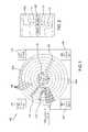
- FIG. 1illustrated is a schematic view of a portion of a human-machine interface (HMI) 100 according to one or more aspects of the present disclosure.
- the HMI 100may be utilized by a human operator during directional and/or other drilling operations to monitor the relationship between toolface orientation and quill position.
- the HMI 100is one of several display screens selectable by the user during drilling operations, and may be included as or in association with the human-machine interface(s), drilling operations and/or drilling apparatus described in one or more of U.S. Pat. No. 6,050,348, issued to Richardson, et al., entitled “Drilling Method and Apparatus;” or U.S. Publication No.
- the HMI 100may also be implemented as a series of instructions recorded on a computer-readable medium, such as described in one or more of these references.
- the HMI 100can be used by the directional driller while drilling to monitor the BHA in three-dimensional space.
- the control system or computerwhich drives one or more other human-machine interfaces during drilling operation may be configured to also display the HMI 100 .
- the HMI 100may be driven or displayed by a separate control system or computer, and may be displayed on a computer display (monitor) other than that on which the remaining drilling operation screens are displayed.
- the control systemis a closed loop control system that can operate automatically once a well plan is input to the HMI.
- the control system or computer driving the HMI 100can include a “survey” or other data channel, or otherwise can include an apparatus adapted to receive and/or read, or alternatively a means for receiving and/or reading, sensor data relayed from the BHA, a measurement-while-drilling (MWD) assembly, and/or other drilling parameter measurement means, where such relay may be, e.g., via the Wellsite Information Transfer Standard (WITS), WITS Markup Language (WITSML), and/or another data transfer protocol.
- WITSWellsite Information Transfer Standard
- WITSMLWITS Markup Language
- Such electronic datamay include gravity-based toolface orientation data, magnetic-based toolface orientation data, azimuth toolface orientation data, and/or inclination toolface orientation data, among others.
- the electronic dataincludes magnetic-based toolface orientation data when the toolface orientation is less than about 7° relative to vertical, and alternatively includes gravity-based toolface orientation data when the toolface orientation is greater than about 7° relative to vertical. In other embodiments, however, the electronic data may include both gravity- and magnetic-based toolface orientation data.
- the toolface orientation datamay relate the azimuth direction of the remote end of the drill string relative to magnetic North, wellbore high side, and/or another predetermined orientation.
- the inclination toolface orientation datamay relate the inclination of the remote end of the drill string relative to vertical.
- the HMI 100may be depicted as substantially resembling a dial or target shape having a plurality of concentric nested rings 105 .
- the magnetic-based toolface orientation datais represented in the HMI 100 by symbols 110
- the gravity-based toolface orientation datais represented by symbols 115 .
- the HMI 100also includes symbols 120 representing the quill position.
- the magnetic toolface data symbols 110are circular
- the gravity toolface data symbols 115are rectangular
- the quill position data symbols 120are triangular, thus distinguishing the different types of data from each other.
- the symbols 110 , 115 , 120may also or alternatively be distinguished from one another via color, size, flashing, flashing rate, and/or other graphic means.
- the symbols 110 , 115 , 120may indicate only the most recent toolface ( 110 , 115 ) and quill position ( 120 ) measurements.
- the HMI 100may include a historical representation of the toolface and quill position measurements, such that the most recent measurement and a plurality of immediately prior measurements are displayed.
- each ring 105 in the HMI 100may represent a measurement iteration or count, or a predetermined time interval, or otherwise indicate the historical relation between the most recent measurement(s) and prior measurement(s).
- FIG. 1the HMI 100 may include a historical representation of the toolface and quill position measurements, such that the most recent measurement and a plurality of immediately prior measurements are displayed.
- each ring 105 in the HMI 100may represent a measurement iteration or count, or a predetermined time interval, or otherwise indicate the historical relation between the most recent measurement(s) and prior measurement(s).
- each ring 105there are five such rings 105 in the dial (the outermost ring being reserved for other data indicia), with each ring 105 representing a data measurement or relay iteration or count.
- the toolface symbols 110 , 115may each include a number indicating the relative age of each measurement. In other embodiments, color, shape, and/or other indicia may graphically depict the relative age of measurement. Although not depicted as such in FIG. 1 , this concept may also be employed to historically depict the quill position data.
- the HMI 100may also include a data legend 125 linking the shapes, colors, and/or other parameters of the data symbols 110 , 115 , 120 to the corresponding data represented by the symbols.
- the HMI 100may also include a textual and/or other type of indicator 130 of the current tool face mode setting.
- the toolface modemay be set to display only gravitational tool face data, only magnetic toolface data, or a combination thereof (perhaps based on the current toolface and/or drill string end inclination).
- the indicator 130may also indicate the current system time.
- the indicator 130may also identify a secondary channel or parameter being monitored or otherwise displayed by the HMI 100 . For example, in the exemplary embodiment shown in FIG. 1 , the indicator 130 indicates that a combination (“Combo”) toolface mode is currently selected by the user, that the bit depth is being monitored on the secondary channel, and that the current system time is 13:09:04.
- the HMI 100may also include a textual and/or other type of indicator 135 displaying the current or most recent toolface orientation.
- the indicator 135may also display the current toolface measurement mode (e.g., gravitational vs. magnetic).
- the indicator 135may also display the time at which the most recent toolface measurement was performed or received, as well as the value of any parameter being monitored by a second channel at that time. For example, in the exemplary embodiment shown in FIG. 1 , the most recent toolface measurement was measured by a gravitational toolface sensor, which indicated that the toolface orientation was ⁇ 75°, and this measurement was taken at time 13:00:13 relative to the system clock, at which time the bit-depth was most recently measured to be 1830 feet.
- the HMI 100may also include a textual and/or other type of indicator 140 displaying the current or most recent inclination of the remote end of the drill string.
- the indicator 140may also display the time at which the most recent inclination measurement was performed or received, as well as the value of any parameter being monitored by a second channel at that time. For example, in the exemplary embodiment shown in FIG. 1 , the most recent drill string end inclination was 8°, and this measurement was taken at time 13:00:04 relative to the system clock, at which time the bit-depth was most recently measured to be 1830 feet.
- the HMI 100may also include an additional graphical or other type of indicator 140 a displaying the current or most recent inclination.
- the HMI 100may depict the current or most recent inclination with both a textual indicator (e.g., indicator 140 ) and a graphical indicator (e.g., indicator 140 a ).
- the graphical inclination indicator 140 arepresents the current or most recent inclination as an arcuate bar, where the length of the bar indicates the degree to which the inclination varies from vertical.
- the HMI 100may also include a textual and/or other type of indicator 145 displaying the current or most recent azimuth orientation of the remote end of the drill string.
- the indicator 145may also display the time at which the most recent azimuth measurement was performed or received, as well as the value of any parameter being monitored by a second channel at that time. For example, in the exemplary embodiment shown in FIG. 1 , the most recent drill string end azimuth was 67°, and this measurement was taken at time 12:59:55 relative to the system clock, at which time the bit-depth was most recently measured to be 1830 feet.
- the HMI 100may also include an additional graphical or other type of indicator 145 a displaying the current or most recent inclination.
- the HMI 100may depict the current or most recent inclination with both a textual indicator (e.g., indicator 145 ) and a graphical indicator (e.g., indicator 145 a ).
- the graphical azimuth indicator 145 arepresents the current or most recent azimuth measurement as an arcuate bar, where the length of the bar indicates the degree to which the azimuth orientation varies from true North or some other predetermined position.
- FIG. 1an example of a toolface advisory sector is displayed showing an example toolface advisory of 250 degrees.
- thisis the preferred angular zone within which the driller or directional driller, or automated drilling program, should endeavor to keep his, or its, toolface readings.
- the drillerwill adjust the settings on the drilling apparatus to keep it within this zone.
- the most recent toolface and quill position measurementsmay be closest to the edge of the dial, such that older readings may step toward the middle of the dial.
- the last readingwas 8 minutes before the currently-depicted system time
- the next readingwas also received in the 8 th minute before the currently-depicted system time
- the oldest readingwas received in the 9 th minute before the currently-depicted system time.
- Readings that are hours or seconds oldmay indicate the length/unit of time with an “h” for hours or a format such as “:25” for twenty five seconds before the currently-depicted system time.
- positioning the user's mouse pointer or other graphical user-input means over one of the toolface or quill position symbols 110 , 115 , 120may show the symbol's timestamp, as well as the secondary indicator (if any), in a pop-up window 150 .
- Timestampsmay be dependent upon the device settings at the actual time of recording the measurement.
- the toolface symbols 110 , 115may show the time elapsed from when the measurement is recorded by the sensing device (e.g., relative to the current system time).
- Secondary channels set to display a timestampmay show a timestamp according to the device recording the measurement.
- the HMI 100shows the absolute quill position referenced to true North, hole high-side, or to some other predetermined orientation.
- the HMI 100also shows current and historical toolface data received from the downhole tools (e.g., MWD).
- the HMI 100 , other human-machine interfaces within the scope of the present disclosure, and/or other tools within the scope of the present disclosuremay have, enable, and/or exhibit a simplified understanding of the effect of reactive torque on toolface measurements, by accurately monitoring and simultaneously displaying both toolface and quill position measurements to the user.
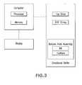
- FIG. 3is a block diagram of a system including the display and a cooperating directional driller and computer.
- the directional drillerincludes a top drive that may include a quill and includes a BHA with a bit and a steerable motor with toolface.
- a drill stringis disposed between the BHA and the top drive.
- the directional drilleris in communication with a computer having a memory and processor and data representing the quill position and the toolface orientation is communicated from the directional driller on an ongoing basis to the computer.
- the computerprocesses the data and preferably displays data on the display in the manner discussed herein.
- the present disclosureintroduces a method of visibly demonstrating a relationship between toolface orientation and quill position, such method including: (1) receiving electronic data preferably on an on-going basis, wherein the electronic data includes quill position data and at least one of gravity-based toolface orientation data and magnetic-based toolface orientation data; and (2) displaying the electronic data on a user-viewable display in a historical format depicting data resulting from a most recent measurement and a plurality of immediately prior measurements.
- the electronic datamay further include azimuth data, relating the azimuth orientation of the drill string adjacent the bit.
- the distance between the bit and sensor(s) gathering the electronic datais preferably as small as possible while still obtaining at least sufficiently, or entirely, accurate readings, and the minimum distance necessary to obtain accurate readings without drill bit interference will be known or readily determined by those of ordinary skill in the art.
- the electronic datamay further include toolface azimuth data, relating the azimuth orientation of the drill string near the bit.
- the electronic datamay further include toolface inclination data, relating the inclination of the drill string near the bit.
- the quill position datamay relate the orientation of the quill, top drive, kelly, and/or other rotary drive means or mechanism to the bit and/or toolface.
- the electronic datamay be received from MWD and/or other downhole sensor/measurement equipment or means.
- the methodmay further include associating the electronic data with time indicia based on specific times at which measurements yielding the electronic data were performed.
- the most current datamay be displayed textually and older data may be displayed graphically, such as a preferably dial- or target-shaped representation.
- different graphical shapescan be used, such as oval, square, triangle, or shapes that are substantially similar but with visual differences, e.g., rounded corners, wavy lines, or the like. Nesting of the different information is preferred.
- the graphical displaymay include time-dependent or time-specific symbols or other icons, which may each be user-accessible to temporarily display data associated with that time (e.g., pop-up data).
- the iconsmay have a number, text, color, or other indication of age relative to other icons.
- the iconspreferably may be oriented by time, newest at the dial edge, oldest at the dial center. In an alternative embodiment, the icons may be oriented in the opposite fashion, with the oldest at the dial edge and the newer information towards the dial center.
- the iconsmay depict the change in time from (1) the measurement being recorded by a corresponding sensor device to (2) the current computer system time.
- the displaymay also depict the current system time.
- the present disclosurealso introduces an apparatus including: (1) apparatus adapted to receive, or a means for receiving, electronic data on an on-going basis or alternatively a recurring basis, wherein the electronic data includes quill position data and at least one of gravity-based toolface orientation data and magnetic-based toolface orientation data; and (2) apparatus adapted to display, or a means for displaying, the electronic data on a user-viewable display in a historical format depicting data resulting from a most recent measurement and a plurality of immediately prior measurements.
- Embodiments within the scope of the present disclosuremay offer certain advantages over the prior art. For example, when toolface and quill position data are combined on a single visual display, it may help an operator or other human personnel to understand the relationship between toolface and quill position, and help the operator adjust the drilling apparatus to move the toolface in the correct direction. Combining toolface and quill position data on a single display may also or alternatively aid understanding of the relationship that reactive torque has with toolface and/or quill position. These advantages may be recognized during vertical drilling, horizontal drilling, directional drilling, and/or correction runs.
- the quillcan be rotated back and forth, or “rocked,” through a desired toolface position about 1 ⁇ 8 to about 8 revolutions in each direction, preferably through about 1 ⁇ 2 to about 4 revolutions, to decrease the friction in the well during drilling.
- the quillcan oscillate 5 revolutions in each direction. This rocking can advantageously be achieved by knowledge of the quill position, particularly when taken in combination with the toolface position data.
- the downhole tool and the top drive at the surfacecan be operatively associated to facilitate orientation of the toolface.
- the WOBcan be increased or decreased and torqued to turn the pipe and therefore pull the toolface around to a new direction as desired.
- back and forth rockingcan be automated and used to help steer drilling by setting a target, e.g., 1000 ft north of the present location, and having the HMI direct the drill towards that target.
- the scoring discussed hereincan be tracked and applied to make improved drilling a challenging game rather than merely a job task.
- the oscillationcan be asymmetrical, which can advantageously facilitate turning the toolface and the drilling to a different direction.
- the pipecan be rotated 4 revolutions clockwise and then 6 counter-clockwise, or 7 times clockwise and then 3 counter-clockwise, and then generally as needed randomly or in a pattern to move the drilling bearing closer to the direction of the target.
- This rockingcan all be achieved without altering the WOB.
- the asymmetrical degree of oscillationcan be reduced as the toolface and drilling begin to approach the desired pre-set heading towards the target.
- the rockingmay begin with 4 clockwise and 6 counter-clockwise, then become 41 ⁇ 2 and 51 ⁇ 2, then become symmetrical once a desired heading is achieved. Additional points in between at 1 ⁇ 8 or 1 ⁇ 4 revolution increments (or larger, like 1 ⁇ 2 or 1) may be selected to more precisely steer the drilling to a target heading.
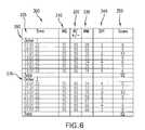
- a scorecard 200may be used to more accurately evaluate a driller's ability to keep the toolface in the correct orientation.
- the scorecard 200may be implemented as a series of instructions recorded on a computer-readable medium.
- the scorecardmay be implemented in hardcopy, such as in a paper notebook, an easel, or on a whiteboard or posting board on a wall.
- a desired or toolface advisory TFD 210may be determined to steer the well to a target or along a well plan.
- the TFD 210may be entered into the scorecard 200 from the rigsite or remotely, such as, for example, over an internet connection.
- the TFD 210may also have an acceptable minimum and maximum tolerance TFT 220 , which may be entered into the scorecard 200 from the rigsite or remotely.
- a measured toolface angle TFM 230may be received from the BHA, MWD, and/or other drilling parameter measurement means.
- the TFM 230may include gravity-based toolface orientation, magnetic-based toolface orientation data, and/or gyroscopic toolface orientation data. These measurements may be made downhole, stored in solid-state memory for some time, and downloaded from the instrument(s) at the surface and/or transmitted to the surface.
- Data transmission methodsmay include any available method known to those of ordinary skill in the art, for example, digitally encoding data and transmitting the encoded data to the surface, as pressure pulses in the drilling fluid or mud system, acoustic transmission through the drill string, electronically transmitted through a wireline or wired pipe, and/or transmitted as electromagnetic pulses.
- the data relaymay be via the WITS, WITSML, and/or another data transfer protocol.
- the measurement performed by the sensors described abovemay be performed once, continuously, periodically, and/or at random intervals.
- the measurementmay be manually triggered by an operator or other person accessing a human-machine interface (HMI), or automatically triggered by, for example, a triggering characteristic or parameter satisfying a predetermined condition (e.g., expiration of a time period, drilling progress measured by reaching a predetermined depth or bit length, drill bit usage reaching a predetermined amount, etc.).
- a predetermined conditione.g., expiration of a time period, drilling progress measured by reaching a predetermined depth or bit length, drill bit usage reaching a predetermined amount, etc.
- the measurementis taken every two hours and the time 235 is displayed for every measurement.
- the difference 240 between TFD 210 and TFM 230may be displayed, or, alternatively, or in addition to, the percent difference between TFD and TFM may be displayed.
- a further embodimentwould be to score any toolface reading acquired as being inside or outside the toolface advisory sector, which could preferably be scored to provide a score based on the number of toolface results received that are inside the toolface advisory sector compared to the total number of toolface results received, expressed as a percentage or fraction.
- the difference 240may result in a score 250 for each time 235 .
- the score 250may be calculated to provide a higher amount of points for the TFM 230 being closer to the TFD 210 . For example, 10 points may be awarded for being on target, 5 points for being 5 degrees off target, 0 points for being 10 degrees or more off target.
- Variations within 0-5 and 5-10 degreescan be linear, or can be arranged to drop off more steeply in non-linear fashion the further off target the result. For example, 10 points may be awarded for being on target, 8 points for being 1 degree off target, 5 points for being 2 degrees off target, 1 point for being 3 degrees off target, and no points for more inaccurate drilling.
- the scoringcan be varied over time, such as to normalize scores based on length of time drilling on a given day.
- the scoring at each timecan be arranged so that the penalty is minimal within the toolface tolerance TFM 230 , e.g., where the difference 240 is less than the TFM 230 , the score is the maximum possible or the score decreases at a slower rate than when the difference 240 is greater than the TFM 230 .
- 1 pointcan be deducted from the maximum score per 1 degree within the tolerance, versus a deduction of 2 points from the maximum per 1 degree outside the tolerance.
- Any of the plethora of alternative scoring methodsare also within the scope of the present disclosure using these embodiments as a guide.
- the current score 250may be displayed on the HMI 100 as the drilling operation is conducted.
- the scorecard 200may be kept for various drillers that may occupy the controls of the drilling rig, for example, a day shift driller 260 and a night shift driller 270 could compete to see who could accumulate the most points.
- a scorecard 200may be kept for an automated drilling program, such as, for example, the RockitTM Pilot available from Nabors Industries to compare to a human driller's record to evaluate if human drillers can achieve, exceed, or minimize differences from, the scores achieved by such automated drilling equipment working off a well plan.
- the scorecard 200could be used as part of an incentive program to reward accurate drilling performance, either through peer recognition, financial rewards (e.g., adjusted upwards or downwards), or both.
- a scorecard 300may be used to more accurately evaluate a driller's ability to keep the BHA in the correct inclination.
- a desired or target inclination angle IAD 310may be determined to steer the well to a target or along a well plan.
- the IAD 310may be entered into the scorecard 300 from the rigsite or remotely, such as, for example, over an internet connection.
- the IAD 310may also have an acceptable minimum and maximum tolerance IAT 320 which may be entered into the scorecard 300 from the rigsite or remotely.
- the measured inclination angle IAM 330may be received from the BHA, MWD, and/or other drilling parameter measurement means.
- the measurementis taken every two hours and the time 335 is displayed for every measurement.
- the difference 340 between IAD 310 and IAM 330may be displayed, or, alternatively, or in addition to, the percent difference between TFD and TFM may be displayed.
- the difference 340may result in a score 350 for each time 335 .
- the score 350may be calculated to provide a higher amount of points for the IAM 330 being closer to the IAD 310 . For example, 10 points may be awarded for being on target, 5 points for being 5 degrees off target, 0 points for being 10 degrees or more off target. Alternative scoring methods are also within the scope of the present disclosure, including without limitation any of those noted above.
- the scorecard 300may be kept for various drillers that may occupy the controls of the drilling rig, for example as noted herein.
- the scorecard 300may be kept for an automated drilling program, such as, for example, the RockitTM Pilot available from Nabors Industries.
- the scorecard 300could be used as part of an incentive program to reward accurate drilling performance, as noted herein.
- the score 350may be displayed on the HMI 100 .
- the automated drilling systemcan be scored against itself, or alternatively, itself under various drilling conditions, based on certain types of geologic formations, or the like.
- the automated drilling systemcan also, in one embodiment, be compared against human drillers on the same rig.
- a scorecard 400may be used to more accurately evaluate a driller's ability to keep the BHA in the correct azimuth.
- a desired or target azimuth angle AAD 410may be determined to steer the well to a target or along a well plan.
- the AAD 410may be entered into the scorecard 400 from the rigsite or remotely, such as, for example, over an internet connection.
- the AAD 410may also have an acceptable minimum and maximum tolerance AAT 420 which may be entered into the scorecard 400 from the rigsite or remotely.
- the measured azimuth angle AAM 430may be received from the BHA, MWD, and/or other drilling parameter measurement means.
- the measurementis taken every two hours and the time 435 is displayed for every measurement.
- the difference 440 between AAD 410 and AAM 430may be displayed, or, alternatively, or in addition to, the percent difference between AAD and AAM may be displayed.
- the difference 440may result in a score 450 for each time 435 .
- the score 450may be calculated to provide a higher amount of points for the AAM 430 being closer to the AAD 410 according to any of the methods discussed herein. Alternative scoring methods are also within the scope of the present disclosure.
- the scorecard 400may be kept for various drillers as discussed herein.
- the scorecard 400may be kept for an automated drilling program, such as, for example, the RockitTM Pilot available from Nabors Industries.
- the scorecard 400could be used as part of an incentive program to reward accurate drilling performance, as discussed herein.
- the scoringcan be used to help determine the need for training.
- the scoringcan help determine the cause of drilling errors, e.g., equipment failures or inaccuracies, the well plan, the driller and human drilling error, or unexpected underground formations, or some combination of these reasons.
- the score 350may be displayed on the HMI 100 .
- a scorecardcould include one or more scorecards 200 , 300 and/or 400 or information from one or more of these scorecards in any suitable arrangement to track progress in drilling accuracy.
- the score 250 , 350 , or 450may be displayed on the HMI 100 . This progress can include that for a single driller over time, for two or more drillers on the same rig or working on the same well plan, or for a team of drillers, e.g., those drilling in similar underground formations.
- the methodcan include or can further include monitoring an actual weight parameter associated with a downhole steerable motor (e.g., measured near the motor, such as within about 100 feet), monitoring a weight parameter measured at the surface, recording the actual weight on bit parameter, recording the weight parameter measured at the surface, recording the difference between the actual weight on bit parameter and a desired weight on bit parameter, and scoring the difference between the actual weight on bit parameter and the desired weight on bit parameter.
- a downhole steerable motore.g., measured near the motor, such as within about 100 feet
- the weight parameter measured at the surfacemay be compared to the actual weight on bit parameters to gain an understanding of the relationship between surface weight and actual weight on the bit. This relationship will provide an ability to drill ahead using downhole data to manage feedoff of an autodriller or a driller.
- scoringcould also be affected by drilling occurrences, such as mud motor stalls or unplanned equipment sidetracks or the need to withdraw the entire drill string, which would typically carry a heavy scoring penalty.
- the present disclosureintroduces a method of guiding or steering drilling of a wellbore, the method including: (1) monitoring an actual toolface orientation of the downhole steerable motor by monitoring a drilling operation parameter indicative of a difference between the actual toolface orientation and a toolface advisory; and (2) adjusting the drilling apparatus to move the toolface in the toolface advisory.
- the methodscan alternatively or additionally be used to evaluate performance during drilling.
- the methodoptionally includes (3) recording the difference between the actual toolface orientation and a toolface advisory; and (4) scoring the difference between the actual toolface orientation and a toolface advisory.
- the recording the difference between the actual toolface orientation and a toolface advisorymay be performed at regularly occurring time intervals and/or at regularly occurring length intervals.
- the scoring the difference between the actual toolface orientation and a toolface advisorymay be performed for various drillers that may occupy the controls of the drilling rig.
- the methodmay further or alternatively include: (1) monitoring an actual inclination angle of a downhole steerable motor by monitoring a drilling operation parameter indicative of a difference between the actual inclination angle and a desired inclination angle; (2) recording the difference between the actual inclination angle and a desired inclination angle; and (3) scoring the difference between the actual inclination angle and a desired inclination angle.
- the methodmay further or alternatively include: (1) monitoring an actual azimuthal angle of the downhole steerable motor by monitoring a drilling operation parameter indicative of a difference between the actual azimuthal angle and a desired azimuthal angle; (2) recording the difference between the actual azimuthal angle and a desired azimuthal angle; and (3) scoring the difference between the actual azimuthal angle and a desired azimuthal angle.
- the present disclosurealso introduces an apparatus for evaluating performance in drilling a wellbore, the apparatus including: (1) a sensor configured to detect a drilling operation parameter indicative of a difference between the actual toolface orientation of a downhole steerable motor and a toolface advisory; and optionally, but preferably, (2) a controller configured to score the difference between the actual toolface orientation and a toolface advisory.
- the apparatusmay further include: a recorder to record the difference between the actual toolface orientation and a toolface advisory.
- the apparatusmay further include: (1) a sensor configured to detect a drilling operation parameter indicative of a difference between the actual inclination angle and a desired inclination angle and (2) a controller configured to score the difference between the actual inclination angle and a desired inclination angle.
- the apparatusmay further include: (1) a sensor configured to detect a drilling operation parameter indicative of a difference between the actual azimuthal angle and a desired azimuthal angle; and (2) a controller configured to score the difference between the actual azimuthal angle and a desired azimuthal angle.
- the present disclosurealso introduces a system for evaluating drilling performance, the system including means for monitoring an actual toolface orientation of the downhole steerable motor by monitoring a drilling operation parameter indicative of a difference between the actual toolface orientation and a toolface advisory, means for recording the difference between the actual toolface orientation and the toolface advisory, means for scoring the difference between the actual toolface orientation and the toolface advisory by assigning a value to the difference that is representative of drilling accuracy and varies depending on the difference; and, optionally but preferably, means for providing the value to an evaluator.
- the means for providing the valuemay include, i.e., a printout, an electronic display, or the like, and the value may be simply the score or it may be or include a comparison based on further calculations using the value compared to values from the same driller, another driller, or an automated drilling program on the same day, at the same rigsite, or another variable where drilling accuracy is desired to be compared.
- the inventioncan also encompass a method of evaluating an automated drilling system that takes control of the establishing and maintaining the toolface, as well as driller job performance in a wellbore, by monitoring the actual toolface orientation of a tool, such as a downhole steerable motor assembly, by monitoring a drilling operation parameter indicative of a difference between the actual toolface orientation and a toolface advisory, recording the difference between the actual toolface orientation and the toolface advisory, and scoring the difference between the actual toolface orientation and the toolface advisory by assigning a value to the difference that represents drilling performance and varies depending on the difference.
- the values between the automated drilling system and the driller job performancecan be compared to provide a difference.
- the inventionfurther encompasses providing the value or values to an evaluator.
- the present inventionencompasses systems, apparatus, and methods for guiding or directing a drilling operation.
- the recommended toolface orientationi.e., toolface advisory, may be used either with or without the scoring discussed in the present disclosure.
- quill positionmay refer to the static rotational orientation of the quill relative to the rotary drive, magnetic North, and/or some other predetermined reference.
- Quill positionmay alternatively or additionally refer to the dynamic rotational orientation of the quill, such as where the quill is oscillating in clockwise and counterclockwise directions about a neutral orientation that is substantially midway between the maximum clockwise rotation and the maximum counterclockwise rotation, in which case the “quill position” may refer to the relation between the neutral orientation or oscillation midpoint and magnetic North or some other predetermined reference.
- the “quill position”may herein refer to the rotational orientation of a rotary drive element other than the quill conventionally utilized with a top drive.
- the quill positionmay refer to the rotational orientation of a rotary table or other surface-residing component utilized to impart rotational motion or force to the drill string.
- the present disclosuremay sometimes refer to a display integrating quill position and toolface orientation, such reference is intended to further include reference to a display integrating drill string position or orientation at the surface with the downhole toolface orientation.
Landscapes
- Life Sciences & Earth Sciences (AREA)
- Engineering & Computer Science (AREA)
- Geology (AREA)
- Mining & Mineral Resources (AREA)
- Physics & Mathematics (AREA)
- Environmental & Geological Engineering (AREA)
- Fluid Mechanics (AREA)
- General Life Sciences & Earth Sciences (AREA)
- Geochemistry & Mineralogy (AREA)
- Geophysics (AREA)
- Drilling And Boring (AREA)
- Earth Drilling (AREA)
Abstract
Description
Claims (20)
Priority Applications (1)
| Application Number | Priority Date | Filing Date | Title |
|---|---|---|---|
| US12/855,035US8528663B2 (en) | 2008-12-19 | 2010-08-12 | Apparatus and methods for guiding toolface orientation |
Applications Claiming Priority (3)
| Application Number | Priority Date | Filing Date | Title |
|---|---|---|---|
| US12/339,350US7802634B2 (en) | 2007-12-21 | 2008-12-19 | Integrated quill position and toolface orientation display |
| US12/390,229US8510081B2 (en) | 2009-02-20 | 2009-02-20 | Drilling scorecard |
| US12/855,035US8528663B2 (en) | 2008-12-19 | 2010-08-12 | Apparatus and methods for guiding toolface orientation |
Related Parent Applications (1)
| Application Number | Title | Priority Date | Filing Date |
|---|---|---|---|
| US12/339,350Continuation-In-PartUS7802634B2 (en) | 2007-12-21 | 2008-12-19 | Integrated quill position and toolface orientation display |
Publications (2)
| Publication Number | Publication Date |
|---|---|
| US20110024191A1 US20110024191A1 (en) | 2011-02-03 |
| US8528663B2true US8528663B2 (en) | 2013-09-10 |
Family
ID=43525947
Family Applications (1)
| Application Number | Title | Priority Date | Filing Date |
|---|---|---|---|
| US12/855,035Active2029-12-01US8528663B2 (en) | 2008-12-19 | 2010-08-12 | Apparatus and methods for guiding toolface orientation |
Country Status (1)
| Country | Link |
|---|---|
| US (1) | US8528663B2 (en) |
Cited By (44)
| Publication number | Priority date | Publication date | Assignee | Title |
|---|---|---|---|---|
| US20140049401A1 (en)* | 2012-08-14 | 2014-02-20 | Yuxin Tang | Downlink Path Finding for Controlling The Trajectory while Drilling A Well |
| US9784089B2 (en) | 2006-12-07 | 2017-10-10 | Nabors Drilling Technologies Usa, Inc. | Automated directional drilling apparatus and methods |
| US9784035B2 (en) | 2015-02-17 | 2017-10-10 | Nabors Drilling Technologies Usa, Inc. | Drill pipe oscillation regime and torque controller for slide drilling |
| US10018028B2 (en)* | 2011-12-22 | 2018-07-10 | Motive Drilling Technologies, Inc. | System and method for surface steerable drilling |
| US10094209B2 (en) | 2014-11-26 | 2018-10-09 | Nabors Drilling Technologies Usa, Inc. | Drill pipe oscillation regime for slide drilling |
| US10378282B2 (en) | 2017-03-10 | 2019-08-13 | Nabors Drilling Technologies Usa, Inc. | Dynamic friction drill string oscillation systems and methods |
| US10550642B2 (en) | 2015-12-15 | 2020-02-04 | Schlumberger Technology Corporation | Well construction display |
| US10577864B2 (en) | 2014-06-24 | 2020-03-03 | Iggillis Holdings Inc. | Method and system for drilling a borehole |
| US10612307B2 (en) | 2014-08-28 | 2020-04-07 | Schlumberger Technology Corporation | Method and system for directional drilling |
| US10672154B2 (en) | 2016-02-24 | 2020-06-02 | Nabors Drilling Technologies Usa, Inc. | 3D toolface wellbore steering visualization |
| US10760417B2 (en) | 2018-01-30 | 2020-09-01 | Schlumberger Technology Corporation | System and method for surface management of drill-string rotation for whirl reduction |
| US10782197B2 (en) | 2017-12-19 | 2020-09-22 | Schlumberger Technology Corporation | Method for measuring surface torque oscillation performance index |
| US10883356B2 (en) | 2014-04-17 | 2021-01-05 | Schlumberger Technology Corporation | Automated sliding drilling |
| US10895142B2 (en) | 2017-09-05 | 2021-01-19 | Schlumberger Technology Corporation | Controlling drill string rotation |
| US10927658B2 (en) | 2013-03-20 | 2021-02-23 | Schlumberger Technology Corporation | Drilling system control for reducing stick-slip by calculating and reducing energy of upgoing rotational waves in a drillstring |
| US10954773B2 (en) | 2017-08-10 | 2021-03-23 | Motive Drilling Technologies, Inc. | Apparatus and methods for automated slide drilling |
| US11015442B2 (en) | 2012-05-09 | 2021-05-25 | Helmerich & Payne Technologies, Llc | System and method for transmitting information in a borehole |
| US11028684B2 (en) | 2011-12-22 | 2021-06-08 | Motive Drilling Technologies, Inc. | System and method for determining the location of a bottom hole assembly |
| US11078781B2 (en) | 2014-10-20 | 2021-08-03 | Helmerich & Payne Technologies, Llc | System and method for dual telemetry noise reduction |
| US11085283B2 (en) | 2011-12-22 | 2021-08-10 | Motive Drilling Technologies, Inc. | System and method for surface steerable drilling using tactical tracking |
| US11106185B2 (en) | 2014-06-25 | 2021-08-31 | Motive Drilling Technologies, Inc. | System and method for surface steerable drilling to provide formation mechanical analysis |
| US11162356B2 (en) | 2019-02-05 | 2021-11-02 | Motive Drilling Technologies, Inc. | Downhole display |
| US11286719B2 (en) | 2011-12-22 | 2022-03-29 | Motive Drilling Technologies, Inc. | Systems and methods for controlling a drilling path based on drift estimates |
| US11352871B2 (en) | 2020-05-11 | 2022-06-07 | Schlumberger Technology Corporation | Slide drilling overshot control |
| US11396801B2 (en) | 2019-09-12 | 2022-07-26 | Schlumberger Technology Corporation | Displaying steering response with uncertainty in a heat map ellipse |
| US11414978B2 (en) | 2017-08-10 | 2022-08-16 | Motive Drilling Technologies, Inc. | Apparatus and methods for uninterrupted drilling |
| US11421520B2 (en) | 2018-03-13 | 2022-08-23 | Ai Driller, Inc. | Drilling parameter optimization for automated well planning, drilling and guidance systems |
| US11466556B2 (en) | 2019-05-17 | 2022-10-11 | Helmerich & Payne, Inc. | Stall detection and recovery for mud motors |
| US11624666B2 (en) | 2018-06-01 | 2023-04-11 | Schlumberger Technology Corporation | Estimating downhole RPM oscillations |
| US11719087B2 (en) | 2018-08-24 | 2023-08-08 | Nabors Drilling Technologies USA, Ino. | Modeling friction along a wellbore |
| US11725494B2 (en) | 2006-12-07 | 2023-08-15 | Nabors Drilling Technologies Usa, Inc. | Method and apparatus for automatically modifying a drilling path in response to a reversal of a predicted trend |
| US11767749B2 (en) | 2020-04-15 | 2023-09-26 | Ensign Drilling Inc | Inertial compensation for a quill oscillator |
| US11808133B2 (en) | 2019-05-28 | 2023-11-07 | Schlumberger Technology Corporation | Slide drilling |
| US11814943B2 (en) | 2020-12-04 | 2023-11-14 | Schlumberger Technoloyg Corporation | Slide drilling control based on top drive torque and rotational distance |
| US11885212B2 (en) | 2021-07-16 | 2024-01-30 | Helmerich & Payne Technologies, Llc | Apparatus and methods for controlling drilling |
| US11916507B2 (en) | 2020-03-03 | 2024-02-27 | Schlumberger Technology Corporation | Motor angular position control |
| US11933158B2 (en) | 2016-09-02 | 2024-03-19 | Motive Drilling Technologies, Inc. | System and method for mag ranging drilling control |
| US11933156B2 (en) | 2020-04-28 | 2024-03-19 | Schlumberger Technology Corporation | Controller augmenting existing control system |
| US11939820B2 (en) | 2018-07-23 | 2024-03-26 | Helmerich & Payne, Inc. | Systems and methods for tubular element handling |
| US12014482B2 (en) | 2018-10-22 | 2024-06-18 | Motive Drilling Technologies, Inc. | Systems and methods for oilfield drilling operations using computer vision |
| US12049822B2 (en) | 2018-10-22 | 2024-07-30 | Motive Drilling Technologies, Inc. | Systems and methods for oilfield drilling operations using computer vision |
| US12196069B2 (en) | 2014-06-25 | 2025-01-14 | Motive Drilling Technologies, Inc. | Surface steerable drilling system for use with rotary steerable system |
| US12359551B2 (en) | 2019-02-05 | 2025-07-15 | Magnetic Variation Services, Llc | Geosteering methods and systems for improved drilling performance |
| US12444040B2 (en) | 2024-05-14 | 2025-10-14 | Motive Drilling Technologies, Inc. | Systems and methods for oilfield drilling operations using computer vision |
Families Citing this family (14)
| Publication number | Priority date | Publication date | Assignee | Title |
|---|---|---|---|---|
| US9284832B2 (en) | 2011-06-02 | 2016-03-15 | Baker Hughes Incorporated | Apparatus and method for determining inclination and orientation of a downhole tool using pressure measurements |
| US10422211B2 (en) | 2012-02-22 | 2019-09-24 | Minnovare Pty Ltd. | Apparatus for aligning drilling machines |
| AU2012101210C4 (en)* | 2012-02-22 | 2019-06-27 | Minnovare Pty Ltd | Drill hole orientation apparatus |
| US20150014056A1 (en)* | 2013-07-15 | 2015-01-15 | Ryan Directional Services | Dynamic response apparatus and methods triggered by conditions |
| EP3215898B1 (en)* | 2014-11-03 | 2019-08-07 | Siemens Schweiz AG | Thermostat having configurable interface connections |
| CA2963380A1 (en) | 2014-11-10 | 2016-05-19 | Halliburton Energy Services, Inc. | Feedback based toolface control system for a rotary steerable drilling tool |
| CA2963629A1 (en) | 2014-11-10 | 2016-05-19 | Halliburton Energy Services, Inc. | Gain scheduling based toolface control system for a rotary steerable drilling tool |
| EP3183421A1 (en)* | 2014-11-10 | 2017-06-28 | Halliburton Energy Services, Inc. | Nonlinear toolface control system for a rotary steerable drilling tool |
| WO2016076826A1 (en) | 2014-11-10 | 2016-05-19 | Halliburton Energy Services, Inc. | Advanced toolface control system for a rotary steerable drilling tool |
| US11346215B2 (en) | 2018-01-23 | 2022-05-31 | Baker Hughes Holdings Llc | Methods of evaluating drilling performance, methods of improving drilling performance, and related systems for drilling using such methods |
| US11859487B2 (en)* | 2018-10-11 | 2024-01-02 | Nabors Drilling Technologies Usa, Inc. | Devices, systems and methods to calculate slide stability |
| US10808517B2 (en) | 2018-12-17 | 2020-10-20 | Baker Hughes Holdings Llc | Earth-boring systems and methods for controlling earth-boring systems |
| CN109915019B (en)* | 2019-04-22 | 2023-12-29 | 中铁五局集团建筑工程有限责任公司 | Drilling rod drilling orientation device and orientation method |
| US12116887B2 (en)* | 2021-08-04 | 2024-10-15 | Nabors Drilling Technologies Usa, Inc. | Methods and apparatus to identify and implement downlink command sequence(s) |
Citations (70)
| Publication number | Priority date | Publication date | Assignee | Title |
|---|---|---|---|---|
| US1891329A (en) | 1932-02-23 | 1932-12-20 | Nat Oil Drill Corp | Braking mechanism for rotary oil well drilling apparatus |
| US2005889A (en) | 1932-11-12 | 1935-06-25 | Westinghouse Electric & Mfg Co | Automatic drilling system for rotary drilling equipment |
| US2724574A (en) | 1952-01-29 | 1955-11-22 | Exxon Research Engineering Co | Hydraulic standoff control for pellet impact drilling |
| US3223183A (en) | 1963-08-07 | 1965-12-14 | Justin A Varney | Well drilling apparatus |
| US3265359A (en) | 1962-06-07 | 1966-08-09 | J E Bowden | Automatic tension control systems for oil well drill lines |
| US3407886A (en) | 1965-09-23 | 1968-10-29 | Sun Oil Co | Apparatus for wellbore telemetering |
| US3550697A (en) | 1966-04-27 | 1970-12-29 | Henry Hobhouse | Drilling condition responsive drive control |
| US4492276A (en) | 1982-11-17 | 1985-01-08 | Shell Oil Company | Down-hole drilling motor and method for directional drilling of boreholes |
| US4535972A (en) | 1983-11-09 | 1985-08-20 | Standard Oil Co. (Indiana) | System to control the vertical movement of a drillstring |
| US4662608A (en) | 1984-09-24 | 1987-05-05 | Ball John W | Automatic drilling control system |
| US4854397A (en) | 1988-09-15 | 1989-08-08 | Amoco Corporation | System for directional drilling and related method of use |
| US4958125A (en) | 1988-12-03 | 1990-09-18 | Anadrill, Inc. | Method and apparatus for determining characteristics of the movement of a rotating drill string including rotation speed and lateral shocks |
| SU1668652A1 (en) | 1989-01-04 | 1991-08-07 | М.Г.Эскин | Geomagnetic azimuthal panoramic scanning system for orientation of directional drilling devices |
| US5103920A (en) | 1989-03-01 | 1992-04-14 | Patton Consulting Inc. | Surveying system and method for locating target subterranean bodies |
| US5103919A (en) | 1990-10-04 | 1992-04-14 | Amoco Corporation | Method of determining the rotational orientation of a downhole tool |
| US5205163A (en) | 1990-07-10 | 1993-04-27 | Schlumberger Technology Corporation | Method and apparatus for determining the torque applied to a drillstring at the surface |
| WO1993012318A1 (en) | 1991-12-09 | 1993-06-24 | Patton Bob J | System for controlled drilling of boreholes along planned profile |
| US5358059A (en) | 1993-09-27 | 1994-10-25 | Ho Hwa Shan | Apparatus and method for the dynamic measurement of a drill string employed in drilling |
| US5390748A (en) | 1993-11-10 | 1995-02-21 | Goldman; William A. | Method and apparatus for drilling optimum subterranean well boreholes |
| US5467832A (en) | 1992-01-21 | 1995-11-21 | Schlumberger Technology Corporation | Method for directionally drilling a borehole |
| US5474142A (en) | 1993-04-19 | 1995-12-12 | Bowden; Bobbie J. | Automatic drilling system |
| US5551286A (en) | 1992-02-22 | 1996-09-03 | Schlumberger Technology Corporation | Determination of drill bit rate of penetration from surface measurements |
| US5713422A (en) | 1994-02-28 | 1998-02-03 | Dhindsa; Jasbir S. | Apparatus and method for drilling boreholes |
| US5730234A (en) | 1995-05-15 | 1998-03-24 | Institut Francais Du Petrole | Method for determining drilling conditions comprising a drilling model |
| US5738178A (en) | 1995-11-17 | 1998-04-14 | Baker Hughes Incorporated | Method and apparatus for navigational drilling with a downhole motor employing independent drill string and bottomhole assembly rotary orientation and rotation |
| US5842149A (en) | 1996-10-22 | 1998-11-24 | Baker Hughes Incorporated | Closed loop drilling system |
| US6026912A (en) | 1998-04-02 | 2000-02-22 | Noble Drilling Services, Inc. | Method of and system for optimizing rate of penetration in drilling operations |
| US6029951A (en) | 1998-07-24 | 2000-02-29 | Varco International, Inc. | Control system for drawworks operations |
| US6050348A (en) | 1997-06-17 | 2000-04-18 | Canrig Drilling Technology Ltd. | Drilling method and apparatus |
| US6065332A (en) | 1996-10-04 | 2000-05-23 | Halliburton Energy Services, Inc. | Method and apparatus for sensing and displaying torsional vibration |
| US6092610A (en) | 1998-02-05 | 2000-07-25 | Schlumberger Technology Corporation | Actively controlled rotary steerable system and method for drilling wells |
| US6152246A (en) | 1998-12-02 | 2000-11-28 | Noble Drilling Services, Inc. | Method of and system for monitoring drilling parameters |
| US6155357A (en) | 1997-09-23 | 2000-12-05 | Noble Drilling Services, Inc. | Method of and system for optimizing rate of penetration in drilling operations |
| US6233498B1 (en) | 1998-03-05 | 2001-05-15 | Noble Drilling Services, Inc. | Method of and system for increasing drilling efficiency |
| US6382331B1 (en) | 2000-04-17 | 2002-05-07 | Noble Drilling Services, Inc. | Method of and system for optimizing rate of penetration based upon control variable correlation |
| US6405808B1 (en) | 2000-03-30 | 2002-06-18 | Schlumberger Technology Corporation | Method for increasing the efficiency of drilling a wellbore, improving the accuracy of its borehole trajectory and reducing the corresponding computed ellise of uncertainty |
| US20020104685A1 (en) | 2000-11-21 | 2002-08-08 | Pinckard Mitchell D. | Method of and system for controlling directional drilling |
| US6523623B1 (en) | 2001-05-30 | 2003-02-25 | Validus International Company, Llc | Method and apparatus for determining drilling paths to directional targets |
| US20030051914A1 (en)* | 1999-01-28 | 2003-03-20 | Bittar Michael S. | Electromagnetic wave resistivity tool having a tilted antenna for geosteering within a desired payzone |
| US20040028476A1 (en) | 2000-01-12 | 2004-02-12 | The Charles Machine Works, Inc. | System and method for automatically drilling and backreaming a horizontal bore underground |
| US6757613B2 (en) | 2001-12-20 | 2004-06-29 | Schlumberger Technology Corporation | Graphical method for designing the trajectory of a well bore |
| WO2004055325A1 (en) | 2002-12-18 | 2004-07-01 | Cmte Development Limited | Drilling head position display |
| US6802378B2 (en) | 2002-12-19 | 2004-10-12 | Noble Engineering And Development, Ltd. | Method of and apparatus for directional drilling |
| US6820702B2 (en) | 2002-08-27 | 2004-11-23 | Noble Drilling Services Inc. | Automated method and system for recognizing well control events |
| US6892812B2 (en) | 2002-05-21 | 2005-05-17 | Noble Drilling Services Inc. | Automated method and system for determining the state of well operations and performing process evaluation |
| US7000710B1 (en) | 2002-04-01 | 2006-02-21 | The Charles Machine Works, Inc. | Automatic path generation and correction system |
| US7032689B2 (en) | 1996-03-25 | 2006-04-25 | Halliburton Energy Services, Inc. | Method and system for predicting performance of a drilling system of a given formation |
| US7044239B2 (en) | 2003-04-25 | 2006-05-16 | Noble Corporation | System and method for automatic drilling to maintain equivalent circulating density at a preferred value |
| US7059427B2 (en) | 2003-04-01 | 2006-06-13 | Noble Drilling Services Inc. | Automatic drilling system |
| US7085696B2 (en) | 1996-03-25 | 2006-08-01 | Halliburton Energy Services, Inc. | Iterative drilling simulation process for enhanced economic decision making |
| WO2006079847A1 (en) | 2005-01-26 | 2006-08-03 | Varco I/P, Inc. | A method for facilitating a wellbore operation |
| US20060185899A1 (en) | 1999-09-24 | 2006-08-24 | Vermeer Manufacturing Company | Underground drilling device employing down-hole radar |
| US7096979B2 (en) | 2003-05-10 | 2006-08-29 | Noble Drilling Services Inc. | Continuous on-bottom directional drilling method and system |
| WO2007073430A1 (en) | 2005-11-18 | 2007-06-28 | Exxonmobil Upstream Research Company | Method of drilling and producing hydrocarbons from subsurface formations |
| US20070203651A1 (en) | 2004-10-22 | 2007-08-30 | Baker Hughes Incorporated | Magnetic measurements while rotating |
| WO2008070829A2 (en) | 2006-12-07 | 2008-06-12 | Nabors Global Holdings Ltd. | Automated mse-based drilling apparatus and methods |
| US20080173480A1 (en) | 2007-01-23 | 2008-07-24 | Pradeep Annaiyappa | Method, device and system for drilling rig modification |
| US7404454B2 (en) | 2006-05-05 | 2008-07-29 | Varco I/P, Inc. | Bit face orientation control in drilling operations |
| US20080281525A1 (en) | 2007-05-10 | 2008-11-13 | Nabors Global Holdings Ltd. | Well prog execution facilitation system and method |
| US20090058674A1 (en) | 2007-08-29 | 2009-03-05 | Nabors Global Holdings Ltd. | Real time well data alerts |
| WO2009039448A2 (en) | 2007-09-21 | 2009-03-26 | Nabors Global Holdings, Ltd. | Automated directional drilling apparatus and methods |
| US20090078462A1 (en) | 2007-09-21 | 2009-03-26 | Nabors Global Holdings Ltd. | Directional Drilling Control |
| US20090090555A1 (en) | 2006-12-07 | 2009-04-09 | Nabors Global Holdings, Ltd. | Automated directional drilling apparatus and methods |
| US7546209B2 (en) | 2004-10-28 | 2009-06-09 | Williams Danny T | Formation dip geo-steering method |
| US20090159336A1 (en) | 2007-12-21 | 2009-06-25 | Nabors Global Holdings, Ltd. | Integrated Quill Position and Toolface Orientation Display |
| US7584788B2 (en) | 2004-06-07 | 2009-09-08 | Smith International Inc. | Control method for downhole steering tool |
| US7665533B2 (en) | 2006-10-24 | 2010-02-23 | Omron Oilfield & Marine, Inc. | Electronic threading control apparatus and method |
| US20100121776A1 (en)* | 2008-11-07 | 2010-05-13 | Peter Stenger | Performance monitoring system |
| US7775297B2 (en) | 2006-12-06 | 2010-08-17 | Omron Oilfield & Marine, Inc. | Multiple input scaling autodriller |
| US7882902B2 (en)* | 2006-11-17 | 2011-02-08 | Weatherford/Lamb, Inc. | Top drive interlock |
- 2010
- 2010-08-12USUS12/855,035patent/US8528663B2/enactiveActive
Patent Citations (80)
| Publication number | Priority date | Publication date | Assignee | Title |
|---|---|---|---|---|
| US1891329A (en) | 1932-02-23 | 1932-12-20 | Nat Oil Drill Corp | Braking mechanism for rotary oil well drilling apparatus |
| US2005889A (en) | 1932-11-12 | 1935-06-25 | Westinghouse Electric & Mfg Co | Automatic drilling system for rotary drilling equipment |
| US2724574A (en) | 1952-01-29 | 1955-11-22 | Exxon Research Engineering Co | Hydraulic standoff control for pellet impact drilling |
| US3265359A (en) | 1962-06-07 | 1966-08-09 | J E Bowden | Automatic tension control systems for oil well drill lines |
| US3223183A (en) | 1963-08-07 | 1965-12-14 | Justin A Varney | Well drilling apparatus |
| US3407886A (en) | 1965-09-23 | 1968-10-29 | Sun Oil Co | Apparatus for wellbore telemetering |
| US3550697A (en) | 1966-04-27 | 1970-12-29 | Henry Hobhouse | Drilling condition responsive drive control |
| US4492276B1 (en) | 1982-11-17 | 1991-07-30 | Shell Oil Co | |
| US4492276A (en) | 1982-11-17 | 1985-01-08 | Shell Oil Company | Down-hole drilling motor and method for directional drilling of boreholes |
| US4535972A (en) | 1983-11-09 | 1985-08-20 | Standard Oil Co. (Indiana) | System to control the vertical movement of a drillstring |
| US4662608A (en) | 1984-09-24 | 1987-05-05 | Ball John W | Automatic drilling control system |
| US4854397A (en) | 1988-09-15 | 1989-08-08 | Amoco Corporation | System for directional drilling and related method of use |
| US4958125A (en) | 1988-12-03 | 1990-09-18 | Anadrill, Inc. | Method and apparatus for determining characteristics of the movement of a rotating drill string including rotation speed and lateral shocks |
| SU1668652A1 (en) | 1989-01-04 | 1991-08-07 | М.Г.Эскин | Geomagnetic azimuthal panoramic scanning system for orientation of directional drilling devices |
| US5103920A (en) | 1989-03-01 | 1992-04-14 | Patton Consulting Inc. | Surveying system and method for locating target subterranean bodies |
| US5205163A (en) | 1990-07-10 | 1993-04-27 | Schlumberger Technology Corporation | Method and apparatus for determining the torque applied to a drillstring at the surface |
| US5103919A (en) | 1990-10-04 | 1992-04-14 | Amoco Corporation | Method of determining the rotational orientation of a downhole tool |
| WO1993012318A1 (en) | 1991-12-09 | 1993-06-24 | Patton Bob J | System for controlled drilling of boreholes along planned profile |
| US5467832A (en) | 1992-01-21 | 1995-11-21 | Schlumberger Technology Corporation | Method for directionally drilling a borehole |
| US5551286A (en) | 1992-02-22 | 1996-09-03 | Schlumberger Technology Corporation | Determination of drill bit rate of penetration from surface measurements |
| US5474142A (en) | 1993-04-19 | 1995-12-12 | Bowden; Bobbie J. | Automatic drilling system |
| US5358059A (en) | 1993-09-27 | 1994-10-25 | Ho Hwa Shan | Apparatus and method for the dynamic measurement of a drill string employed in drilling |
| US5390748A (en) | 1993-11-10 | 1995-02-21 | Goldman; William A. | Method and apparatus for drilling optimum subterranean well boreholes |
| US5713422A (en) | 1994-02-28 | 1998-02-03 | Dhindsa; Jasbir S. | Apparatus and method for drilling boreholes |
| US5730234A (en) | 1995-05-15 | 1998-03-24 | Institut Francais Du Petrole | Method for determining drilling conditions comprising a drilling model |
| US5738178A (en) | 1995-11-17 | 1998-04-14 | Baker Hughes Incorporated | Method and apparatus for navigational drilling with a downhole motor employing independent drill string and bottomhole assembly rotary orientation and rotation |
| EP0774563B1 (en) | 1995-11-17 | 2002-07-24 | Baker Hughes Incorporated | Method and apparatus for navigational drilling |
| US7032689B2 (en) | 1996-03-25 | 2006-04-25 | Halliburton Energy Services, Inc. | Method and system for predicting performance of a drilling system of a given formation |
| US7357196B2 (en) | 1996-03-25 | 2008-04-15 | Halliburton Energy Services, Inc. | Method and system for predicting performance of a drilling system for a given formation |
| US7085696B2 (en) | 1996-03-25 | 2006-08-01 | Halliburton Energy Services, Inc. | Iterative drilling simulation process for enhanced economic decision making |
| US6065332A (en) | 1996-10-04 | 2000-05-23 | Halliburton Energy Services, Inc. | Method and apparatus for sensing and displaying torsional vibration |
| US5842149A (en) | 1996-10-22 | 1998-11-24 | Baker Hughes Incorporated | Closed loop drilling system |
| US6050348A (en) | 1997-06-17 | 2000-04-18 | Canrig Drilling Technology Ltd. | Drilling method and apparatus |
| US6155357A (en) | 1997-09-23 | 2000-12-05 | Noble Drilling Services, Inc. | Method of and system for optimizing rate of penetration in drilling operations |
| US6192998B1 (en) | 1997-09-23 | 2001-02-27 | Noble Drilling Services, Inc. | Method of and system for optimizing rate of penetration in drilling operations |
| US6092610A (en) | 1998-02-05 | 2000-07-25 | Schlumberger Technology Corporation | Actively controlled rotary steerable system and method for drilling wells |
| US6233498B1 (en) | 1998-03-05 | 2001-05-15 | Noble Drilling Services, Inc. | Method of and system for increasing drilling efficiency |
| US6293356B1 (en) | 1998-04-02 | 2001-09-25 | Noble Drilling Services, Inc. | Method of and system for optimizing rate of penetration in drilling operations |
| US6026912A (en) | 1998-04-02 | 2000-02-22 | Noble Drilling Services, Inc. | Method of and system for optimizing rate of penetration in drilling operations |
| US6029951A (en) | 1998-07-24 | 2000-02-29 | Varco International, Inc. | Control system for drawworks operations |
| US6152246A (en) | 1998-12-02 | 2000-11-28 | Noble Drilling Services, Inc. | Method of and system for monitoring drilling parameters |
| US20030051914A1 (en)* | 1999-01-28 | 2003-03-20 | Bittar Michael S. | Electromagnetic wave resistivity tool having a tilted antenna for geosteering within a desired payzone |
| US20060185899A1 (en) | 1999-09-24 | 2006-08-24 | Vermeer Manufacturing Company | Underground drilling device employing down-hole radar |
| US20040028476A1 (en) | 2000-01-12 | 2004-02-12 | The Charles Machine Works, Inc. | System and method for automatically drilling and backreaming a horizontal bore underground |
| US6405808B1 (en) | 2000-03-30 | 2002-06-18 | Schlumberger Technology Corporation | Method for increasing the efficiency of drilling a wellbore, improving the accuracy of its borehole trajectory and reducing the corresponding computed ellise of uncertainty |
| US6382331B1 (en) | 2000-04-17 | 2002-05-07 | Noble Drilling Services, Inc. | Method of and system for optimizing rate of penetration based upon control variable correlation |
| US20020104685A1 (en) | 2000-11-21 | 2002-08-08 | Pinckard Mitchell D. | Method of and system for controlling directional drilling |
| US6523623B1 (en) | 2001-05-30 | 2003-02-25 | Validus International Company, Llc | Method and apparatus for determining drilling paths to directional targets |
| US6757613B2 (en) | 2001-12-20 | 2004-06-29 | Schlumberger Technology Corporation | Graphical method for designing the trajectory of a well bore |
| US7000710B1 (en) | 2002-04-01 | 2006-02-21 | The Charles Machine Works, Inc. | Automatic path generation and correction system |
| US6892812B2 (en) | 2002-05-21 | 2005-05-17 | Noble Drilling Services Inc. | Automated method and system for determining the state of well operations and performing process evaluation |
| US6820702B2 (en) | 2002-08-27 | 2004-11-23 | Noble Drilling Services Inc. | Automated method and system for recognizing well control events |
| WO2004055325A1 (en) | 2002-12-18 | 2004-07-01 | Cmte Development Limited | Drilling head position display |
| US6802378B2 (en) | 2002-12-19 | 2004-10-12 | Noble Engineering And Development, Ltd. | Method of and apparatus for directional drilling |
| US7059427B2 (en) | 2003-04-01 | 2006-06-13 | Noble Drilling Services Inc. | Automatic drilling system |
| US7044239B2 (en) | 2003-04-25 | 2006-05-16 | Noble Corporation | System and method for automatic drilling to maintain equivalent circulating density at a preferred value |
| US7096979B2 (en) | 2003-05-10 | 2006-08-29 | Noble Drilling Services Inc. | Continuous on-bottom directional drilling method and system |
| US7584788B2 (en) | 2004-06-07 | 2009-09-08 | Smith International Inc. | Control method for downhole steering tool |
| US20070203651A1 (en) | 2004-10-22 | 2007-08-30 | Baker Hughes Incorporated | Magnetic measurements while rotating |
| US7546209B2 (en) | 2004-10-28 | 2009-06-09 | Williams Danny T | Formation dip geo-steering method |
| US7243735B2 (en) | 2005-01-26 | 2007-07-17 | Varco I/P, Inc. | Wellbore operations monitoring and control systems and methods |
| WO2006079847A1 (en) | 2005-01-26 | 2006-08-03 | Varco I/P, Inc. | A method for facilitating a wellbore operation |
| US20090250264A1 (en) | 2005-11-18 | 2009-10-08 | Dupriest Fred E | Method of Drilling and Production Hydrocarbons from Subsurface Formations |
| WO2007073430A1 (en) | 2005-11-18 | 2007-06-28 | Exxonmobil Upstream Research Company | Method of drilling and producing hydrocarbons from subsurface formations |
| US7404454B2 (en) | 2006-05-05 | 2008-07-29 | Varco I/P, Inc. | Bit face orientation control in drilling operations |
| US7665533B2 (en) | 2006-10-24 | 2010-02-23 | Omron Oilfield & Marine, Inc. | Electronic threading control apparatus and method |
| US7882902B2 (en)* | 2006-11-17 | 2011-02-08 | Weatherford/Lamb, Inc. | Top drive interlock |
| US7775297B2 (en) | 2006-12-06 | 2010-08-17 | Omron Oilfield & Marine, Inc. | Multiple input scaling autodriller |
| US20090090555A1 (en) | 2006-12-07 | 2009-04-09 | Nabors Global Holdings, Ltd. | Automated directional drilling apparatus and methods |
| US20080156531A1 (en) | 2006-12-07 | 2008-07-03 | Nabors Global Holdings Ltd. | Automated mse-based drilling apparatus and methods |
| WO2008070829A2 (en) | 2006-12-07 | 2008-06-12 | Nabors Global Holdings Ltd. | Automated mse-based drilling apparatus and methods |
| US20080173480A1 (en) | 2007-01-23 | 2008-07-24 | Pradeep Annaiyappa | Method, device and system for drilling rig modification |
| US20080281525A1 (en) | 2007-05-10 | 2008-11-13 | Nabors Global Holdings Ltd. | Well prog execution facilitation system and method |
| US20090058674A1 (en) | 2007-08-29 | 2009-03-05 | Nabors Global Holdings Ltd. | Real time well data alerts |
| WO2009039453A2 (en) | 2007-09-21 | 2009-03-26 | Nabors Global Holdings, Ltd. | Directional drilling control |
| US20090078462A1 (en) | 2007-09-21 | 2009-03-26 | Nabors Global Holdings Ltd. | Directional Drilling Control |
| WO2009039448A2 (en) | 2007-09-21 | 2009-03-26 | Nabors Global Holdings, Ltd. | Automated directional drilling apparatus and methods |
| US20090159336A1 (en) | 2007-12-21 | 2009-06-25 | Nabors Global Holdings, Ltd. | Integrated Quill Position and Toolface Orientation Display |
| US7802634B2 (en)* | 2007-12-21 | 2010-09-28 | Canrig Drilling Technology Ltd. | Integrated quill position and toolface orientation display |
| US20100121776A1 (en)* | 2008-11-07 | 2010-05-13 | Peter Stenger | Performance monitoring system |
Non-Patent Citations (30)
| Title |
|---|
| "40223705-Series Wildcat Services Pneumatic Automated Drilling System," available at http://www.nov.com/Drilling/Control-and-Advisiory-Systems/Drawworks-Control-Auto-Drilling/Auto-Drillers.aspx (last visited Oct. 8, 2009). |
| "Wildcat ADS Automated Drilling System," Product Brochure, National Oilwell Varco, Inc. (2006). |
| Answer to Plaintiff's Complaint; Case 6:09-cv-00414-LED; Doc 25; Nov. 6, 2009. |
| Bonner, et al., "Measurements at the Bit: A New Generation of MWD Tools," Oilfield Review, pp. 44-54, Apr./Jul. 1993. |
| Brett, et al., "Field Experiences with Computer-Controlled Drilling," Society of Petroleum Engineers 20107, presented at Permian Basin Oil and Gas Recovery Cortference, Midland, TX (Mar. 8-9, 1990). |
| Brown, et al., "In-Time Data Delivery," Oilfield Review, 11(4): 34-55, http://www.slb.com/media/services/resources/oilfieldreview/ors99/win99/pages34-55.pdf (Winter 1999/2000). |
| Canrig Drilling Technology Ltd,'s Objections and Responses to Helmerick & Payne's First Set of Interrogatories, Civil Action No. 6:09-cv-00414, Aug. 23, 2010. |
| Canrig's Answers to Omron Oilfield and Marine, Inc.'s First Set of Interrogatories, Civil Action No, 6:09-cv-00414, May 7, 2010. |
| Defendant Helmerich & Payne's Invalidity Contentions; Case 6:09-cv-00414-LED; Mar. 25, 2010. |
| Defendant Omron Oilfield and Marine, Inc's Patent Rule 3-3 Disclosures; Case 6:09-cv-00414-LED; Mar. 25, 2010. |
| Defendant Omron Oilfield and Marine, Inc's Patent Rule 3-4 Disclosures; Case 6:09-cv-00414-LED; Mar. 25, 2010. |
| Defendant's Joint Preliminary Claim Construction and Extrinsic Evidence, Civil Action No. 6:09-cv-00414LED, Sep. 24, 2010. |
| Dupriest, et al., "Maximizing Drill Rates with Real-Time Surveillance of Mechanical Specific Energy," SPE/IADC Drilling Conference 92194, Amsterdam, The Netherlands, p. 1-10 (Feb. 23-25, 2005). |
| Dupriest, F., "Comprehensive Drill-Rate Management Process to Maximize Rate of Penetration," SPE Annual Technology Conference and Exhibition, San Antonio, Texas, SPE 102210, p. 1-9 (Sep. 24-27, 2006). |
| Dupriest, F., "Maximizing ROP with Real-Time Analysis of Digital Data and MSE," International Petroleum Technology Conference, Doha, Qatar, p. 1-8 (Nov. 21-23, 2005). |
| Goldman, "Artificial Intelligence Applications Enhance Directional Control," Petroleum Engineer International, pp. 15-22, Feb. 1993. |
| Gurari, E., "CIS 680: Data Structures: Chapter 19: Backtracking Algorithms;" http://www.cse.ohio-state,edu/%7Egurari/course/cis680/cis680Ch19.html (1999). |
| Hartley, et al., "New Drilling Process Increases Rate of Penetration, Footage Per Day," Offshore, 66(1): 1-5 (2006). |
| Helmerich & Payne, Inc.'s First Amended Answer and Counterclaims to Plaintiff's Original Complaint; Case 6:09-cv-00414-LED; Doc 55; Mar. 25, 2010. |
| Jackson, et al., "Portable Top Drive Cuts Horizontal Drilling Costs," World Oil Magazine, vol. 214 Issue 11, pp. 81-89, Nov. 1993. |
| Joint Claim Construction Statement, Civil Action No. 6:09-cv-00414LED, Oct. 25, 2010. |
| Leine, et al., "Stick-Slip Whirl Interaction in Drillstring Dynamics," J. of Vibration and Acoustics, 124: 209-220 (2002). |
| Maidla, et al., "Understanding Torque: The Key to Slide-Drilling Directional Wells," IADC/SPE Drilling Conference, IADC/SPE 87162 (2004). |
| Murch, "Application of Top Drive Drilling to Horizontal Wells," Society of Petroleum Engineers-SPE 37100, 1996. |
| Petroleum Extension Service, "Controlled Directional Drilling," N. Janicek (ed.), Third Edition, pp. 18-33 and 44-45, 1984. |
| Plaintiff Canrig's Local Patent Rule 4-2 Disclosures, Civil Action No. 6:09-cv-00414, Sep. 24, 2010. |
| Plaintiff's Original Complaint; Case 6:09-cv-00414; Doc. 1; Sep. 16, 2009. |
| The International Searching Authority, "Written Opinion of the International Searching Authority," PCT/US2007/86768, mailed Jun. 11, 2008. |
| U.S. Appl. No. 12/390,229, filed Feb. 20, 2009, Boone. |
| Young, Jr., "Computerized Drilling Control," Journal of Petroleum Technology, 21(4): 483-96 (1969). |
Cited By (68)
| Publication number | Priority date | Publication date | Assignee | Title |
|---|---|---|---|---|
| US11434743B2 (en) | 2006-12-07 | 2022-09-06 | Nabors Drilling Technologies Usa, Inc. | Automated directional drilling apparatus and methods |
| US9784089B2 (en) | 2006-12-07 | 2017-10-10 | Nabors Drilling Technologies Usa, Inc. | Automated directional drilling apparatus and methods |
| US11725494B2 (en) | 2006-12-07 | 2023-08-15 | Nabors Drilling Technologies Usa, Inc. | Method and apparatus for automatically modifying a drilling path in response to a reversal of a predicted trend |
| US12264573B2 (en) | 2006-12-07 | 2025-04-01 | Nabors Drilling Technologies Usa, Ltd. | Method and apparatus for steering a bit using a quill and based on learned relationships |
| US10018028B2 (en)* | 2011-12-22 | 2018-07-10 | Motive Drilling Technologies, Inc. | System and method for surface steerable drilling |
| US12241356B2 (en) | 2011-12-22 | 2025-03-04 | Motive Drilling Technologies, Inc. | System and method for drilling a borehole |
| US11828156B2 (en) | 2011-12-22 | 2023-11-28 | Motive Drilling Technologies, Inc. | System and method for detecting a mode of drilling |
| US11028684B2 (en) | 2011-12-22 | 2021-06-08 | Motive Drilling Technologies, Inc. | System and method for determining the location of a bottom hole assembly |
| US10995602B2 (en) | 2011-12-22 | 2021-05-04 | Motive Drilling Technologies, Inc. | System and method for drilling a borehole |
| US11982172B2 (en) | 2011-12-22 | 2024-05-14 | Motive Drilling Technologies, Inc. | System and method for drilling a borehole |
| US11085283B2 (en) | 2011-12-22 | 2021-08-10 | Motive Drilling Technologies, Inc. | System and method for surface steerable drilling using tactical tracking |
| US12297736B2 (en) | 2011-12-22 | 2025-05-13 | Motive Drilling Technologies, Inc. | Systems and methods for controlling a drilling path based on drift estimates |
| US12203361B2 (en) | 2011-12-22 | 2025-01-21 | Motive Drilling Technologies, Inc. | System and method for determining the location of a bottom hole assembly |
| US11286719B2 (en) | 2011-12-22 | 2022-03-29 | Motive Drilling Technologies, Inc. | Systems and methods for controlling a drilling path based on drift estimates |
| US11047222B2 (en) | 2011-12-22 | 2021-06-29 | Motive Drilling Technologies, Inc. | System and method for detecting a mode of drilling |
| US11578593B2 (en) | 2012-05-09 | 2023-02-14 | Helmerich & Payne Technologies, Llc | System and method for transmitting information in a borehole |
| US11015442B2 (en) | 2012-05-09 | 2021-05-25 | Helmerich & Payne Technologies, Llc | System and method for transmitting information in a borehole |
| US9970284B2 (en)* | 2012-08-14 | 2018-05-15 | Schlumberger Technology Corporation | Downlink path finding for controlling the trajectory while drilling a well |
| US20140049401A1 (en)* | 2012-08-14 | 2014-02-20 | Yuxin Tang | Downlink Path Finding for Controlling The Trajectory while Drilling A Well |
| US12091958B2 (en) | 2013-03-20 | 2024-09-17 | Schlumberger Technology Corporation | Drilling system control for reducing stick-slip by calculating and reducing energy of upgoing rotational waves in a drillstring |
| US10927658B2 (en) | 2013-03-20 | 2021-02-23 | Schlumberger Technology Corporation | Drilling system control for reducing stick-slip by calculating and reducing energy of upgoing rotational waves in a drillstring |
| US10883356B2 (en) | 2014-04-17 | 2021-01-05 | Schlumberger Technology Corporation | Automated sliding drilling |
| US10577864B2 (en) | 2014-06-24 | 2020-03-03 | Iggillis Holdings Inc. | Method and system for drilling a borehole |
| US11106185B2 (en) | 2014-06-25 | 2021-08-31 | Motive Drilling Technologies, Inc. | System and method for surface steerable drilling to provide formation mechanical analysis |
| US12196069B2 (en) | 2014-06-25 | 2025-01-14 | Motive Drilling Technologies, Inc. | Surface steerable drilling system for use with rotary steerable system |
| US11105157B2 (en) | 2014-08-28 | 2021-08-31 | Schlumberger Technology Corporation | Method and system for directional drilling |
| US10612307B2 (en) | 2014-08-28 | 2020-04-07 | Schlumberger Technology Corporation | Method and system for directional drilling |
| US11078781B2 (en) | 2014-10-20 | 2021-08-03 | Helmerich & Payne Technologies, Llc | System and method for dual telemetry noise reduction |
| US11846181B2 (en) | 2014-10-20 | 2023-12-19 | Helmerich & Payne Technologies, Inc. | System and method for dual telemetry noise reduction |
| US10094209B2 (en) | 2014-11-26 | 2018-10-09 | Nabors Drilling Technologies Usa, Inc. | Drill pipe oscillation regime for slide drilling |
| US9784035B2 (en) | 2015-02-17 | 2017-10-10 | Nabors Drilling Technologies Usa, Inc. | Drill pipe oscillation regime and torque controller for slide drilling |
| US10550642B2 (en) | 2015-12-15 | 2020-02-04 | Schlumberger Technology Corporation | Well construction display |
| US10672154B2 (en) | 2016-02-24 | 2020-06-02 | Nabors Drilling Technologies Usa, Inc. | 3D toolface wellbore steering visualization |
| US11933158B2 (en) | 2016-09-02 | 2024-03-19 | Motive Drilling Technologies, Inc. | System and method for mag ranging drilling control |
| US10378282B2 (en) | 2017-03-10 | 2019-08-13 | Nabors Drilling Technologies Usa, Inc. | Dynamic friction drill string oscillation systems and methods |
| US11661836B2 (en) | 2017-08-10 | 2023-05-30 | Motive Drilling Technologies, Inc. | Apparatus for automated slide drilling |
| US11414978B2 (en) | 2017-08-10 | 2022-08-16 | Motive Drilling Technologies, Inc. | Apparatus and methods for uninterrupted drilling |
| US11795806B2 (en) | 2017-08-10 | 2023-10-24 | Motive Drilling Technologies, Inc. | Apparatus and methods for uninterrupted drilling |
| US10954773B2 (en) | 2017-08-10 | 2021-03-23 | Motive Drilling Technologies, Inc. | Apparatus and methods for automated slide drilling |
| US12203358B2 (en) | 2017-08-10 | 2025-01-21 | Motive Drilling Technologies, Inc. | Apparatus and methods for uninterrupted drilling |
| US12065924B2 (en) | 2017-08-10 | 2024-08-20 | Motive Drilling Technologies, Inc. | Apparatus for automated slide drilling |
| US10895142B2 (en) | 2017-09-05 | 2021-01-19 | Schlumberger Technology Corporation | Controlling drill string rotation |
| US10782197B2 (en) | 2017-12-19 | 2020-09-22 | Schlumberger Technology Corporation | Method for measuring surface torque oscillation performance index |
| US10760417B2 (en) | 2018-01-30 | 2020-09-01 | Schlumberger Technology Corporation | System and method for surface management of drill-string rotation for whirl reduction |
| US11421520B2 (en) | 2018-03-13 | 2022-08-23 | Ai Driller, Inc. | Drilling parameter optimization for automated well planning, drilling and guidance systems |
| US11624666B2 (en) | 2018-06-01 | 2023-04-11 | Schlumberger Technology Corporation | Estimating downhole RPM oscillations |
| US11939820B2 (en) | 2018-07-23 | 2024-03-26 | Helmerich & Payne, Inc. | Systems and methods for tubular element handling |
| US11719087B2 (en) | 2018-08-24 | 2023-08-08 | Nabors Drilling Technologies USA, Ino. | Modeling friction along a wellbore |
| US12014482B2 (en) | 2018-10-22 | 2024-06-18 | Motive Drilling Technologies, Inc. | Systems and methods for oilfield drilling operations using computer vision |
| US12049822B2 (en) | 2018-10-22 | 2024-07-30 | Motive Drilling Technologies, Inc. | Systems and methods for oilfield drilling operations using computer vision |
| US12359551B2 (en) | 2019-02-05 | 2025-07-15 | Magnetic Variation Services, Llc | Geosteering methods and systems for improved drilling performance |
| US12006818B2 (en) | 2019-02-05 | 2024-06-11 | Motive Drilling Technologies, Inc. | Downhole display |
| US11162356B2 (en) | 2019-02-05 | 2021-11-02 | Motive Drilling Technologies, Inc. | Downhole display |
| US12168924B2 (en) | 2019-05-17 | 2024-12-17 | Helmerich & Payne, Inc. | Stall detection and recovery for mud motors |
| US11466556B2 (en) | 2019-05-17 | 2022-10-11 | Helmerich & Payne, Inc. | Stall detection and recovery for mud motors |
| US11808133B2 (en) | 2019-05-28 | 2023-11-07 | Schlumberger Technology Corporation | Slide drilling |
| US11396801B2 (en) | 2019-09-12 | 2022-07-26 | Schlumberger Technology Corporation | Displaying steering response with uncertainty in a heat map ellipse |
| US11808131B2 (en) | 2019-09-12 | 2023-11-07 | Schlumberger Technology Corporation | Displaying steering response with uncertainty in a heat map ellipse |
| US12359552B2 (en) | 2019-09-12 | 2025-07-15 | Schlumberger Technology Corporation | Displaying steering response with uncertainty in a heat map ellipse |
| US12119775B2 (en) | 2020-03-03 | 2024-10-15 | Schlumberger Technology Corporation | Motor angular position control |
| US11916507B2 (en) | 2020-03-03 | 2024-02-27 | Schlumberger Technology Corporation | Motor angular position control |
| US11767749B2 (en) | 2020-04-15 | 2023-09-26 | Ensign Drilling Inc | Inertial compensation for a quill oscillator |
| US11933156B2 (en) | 2020-04-28 | 2024-03-19 | Schlumberger Technology Corporation | Controller augmenting existing control system |
| US11352871B2 (en) | 2020-05-11 | 2022-06-07 | Schlumberger Technology Corporation | Slide drilling overshot control |
| US11814943B2 (en) | 2020-12-04 | 2023-11-14 | Schlumberger Technoloyg Corporation | Slide drilling control based on top drive torque and rotational distance |
| US11885212B2 (en) | 2021-07-16 | 2024-01-30 | Helmerich & Payne Technologies, Llc | Apparatus and methods for controlling drilling |
| US12366156B2 (en) | 2021-07-16 | 2025-07-22 | Helmerich & Payne Technologies, Llc | Apparatus and methods for controlling drilling |
| US12444040B2 (en) | 2024-05-14 | 2025-10-14 | Motive Drilling Technologies, Inc. | Systems and methods for oilfield drilling operations using computer vision |
Also Published As
| Publication number | Publication date |
|---|---|
| US20110024191A1 (en) | 2011-02-03 |
Similar Documents
| Publication | Publication Date | Title |
|---|---|---|
| US8528663B2 (en) | Apparatus and methods for guiding toolface orientation | |
| US8510081B2 (en) | Drilling scorecard | |
| US7802634B2 (en) | Integrated quill position and toolface orientation display | |
| US10672154B2 (en) | 3D toolface wellbore steering visualization | |
| US10781684B2 (en) | Automated directional steering systems and methods | |
| US11859487B2 (en) | Devices, systems and methods to calculate slide stability | |
| US20210215032A1 (en) | Downhole 3d geo steering viewer for a drilling apparatus | |
| US10794169B2 (en) | Systems, devices, and methods for generating drilling windows | |
| US20190078427A1 (en) | Systems, devices, and methods for generating an adjusted ideal drilling path | |
| WO2020055911A1 (en) | System and method for optimizing drilling with a rotary steerable system | |
| US11136882B2 (en) | Automated drilling instructions for steerable drilling systems | |
| US11434742B2 (en) | Method and apparatus for identifying a potential problem with drilling equipment using a feedback control loop system | |
| US12241359B2 (en) | Methods and systems for drilling | |
| US20240117726A1 (en) | Methods and systems for drilling | |
| US11512577B2 (en) | Steerable drilling bi-directional communications system and methods |
Legal Events
| Date | Code | Title | Description |
|---|---|---|---|
| AS | Assignment | Owner name:CANRIG DRILLING TECHNOLOGY LTD., TEXAS Free format text:ASSIGNMENT OF ASSIGNORS INTEREST;ASSIGNOR:BOONE, SCOTT G.;REEL/FRAME:025133/0095 Effective date:20101007 | |
| STCF | Information on status: patent grant | Free format text:PATENTED CASE | |
| FPAY | Fee payment | Year of fee payment:4 | |
| AS | Assignment | Owner name:NABORS DRILLING TECHNOLOGIES USA, INC., TEXAS Free format text:MERGER;ASSIGNOR:CANRIG DRILLING TECHNOLOGY LTD.;REEL/FRAME:043601/0745 Effective date:20170630 | |
| MAFP | Maintenance fee payment | Free format text:PAYMENT OF MAINTENANCE FEE, 8TH YEAR, LARGE ENTITY (ORIGINAL EVENT CODE: M1552); ENTITY STATUS OF PATENT OWNER: LARGE ENTITY Year of fee payment:8 | |
| IPR | Aia trial proceeding filed before the patent and appeal board: inter partes review | Free format text:TRIAL NO: IPR2021-01044 Opponent name:HELMERICH PAYNE INTERNATIONAL DRILLING COMPANY, HELMERICH PAYNE TECHNOLOGIES, LLC, MOTIVE DRILLING TECHNOLOGIES, INC., AND HELMERICH PAYNE, INC. Effective date:20210614 | |
| RR | Request for reexamination filed | Effective date:20221011 | |
| LIMR | Reexamination decision: claims changed and/or cancelled | Kind code of ref document:C1 Free format text:REEXAMINATION CERTIFICATE; CLAIMS 12 AND 13 ARE CANCELLED. CLAIMS 14, 19 AND 20 ARE DETERMINED TO BE PATENTABLE AS AMENDED. CLAIMS 15-18, DEPENDENT ON AN AMENDED CLAIM, ARE DETERMINED TO BE PATENTABLE. NEW CLAIMS 21-30 ARE ADDED AND DETERMINED TO BE PATENTABLE. CLAIMS 1-11 WERE NOT REEXAMINED. Filing date:20221011 Effective date:20240202 | |
| MAFP | Maintenance fee payment | Free format text:PAYMENT OF MAINTENANCE FEE, 12TH YEAR, LARGE ENTITY (ORIGINAL EVENT CODE: M1553); ENTITY STATUS OF PATENT OWNER: LARGE ENTITY Year of fee payment:12 |