US8528628B2 - Carbon-based apparatus for cooling of electronic devices - Google Patents
Carbon-based apparatus for cooling of electronic devicesDownload PDFInfo
- Publication number
- US8528628B2 US8528628B2US12/012,654US1265408AUS8528628B2US 8528628 B2US8528628 B2US 8528628B2US 1265408 AUS1265408 AUS 1265408AUS 8528628 B2US8528628 B2US 8528628B2
- Authority
- US
- United States
- Prior art keywords
- micro
- daughter
- channels
- channel
- coolant
- Prior art date
- Legal status (The legal status is an assumption and is not a legal conclusion. Google has not performed a legal analysis and makes no representation as to the accuracy of the status listed.)
- Active, expires
Links
Images


Classifications
- H—ELECTRICITY
- H01—ELECTRIC ELEMENTS
- H01L—SEMICONDUCTOR DEVICES NOT COVERED BY CLASS H10
- H01L23/00—Details of semiconductor or other solid state devices
- H01L23/34—Arrangements for cooling, heating, ventilating or temperature compensation ; Temperature sensing arrangements
- H01L23/46—Arrangements for cooling, heating, ventilating or temperature compensation ; Temperature sensing arrangements involving the transfer of heat by flowing fluids
- H01L23/473—Arrangements for cooling, heating, ventilating or temperature compensation ; Temperature sensing arrangements involving the transfer of heat by flowing fluids by flowing liquids
- H01L23/4735—Jet impingement
- F—MECHANICAL ENGINEERING; LIGHTING; HEATING; WEAPONS; BLASTING
- F28—HEAT EXCHANGE IN GENERAL
- F28F—DETAILS OF HEAT-EXCHANGE AND HEAT-TRANSFER APPARATUS, OF GENERAL APPLICATION
- F28F21/00—Constructions of heat-exchange apparatus characterised by the selection of particular materials
- F28F21/02—Constructions of heat-exchange apparatus characterised by the selection of particular materials of carbon, e.g. graphite
- F—MECHANICAL ENGINEERING; LIGHTING; HEATING; WEAPONS; BLASTING
- F28—HEAT EXCHANGE IN GENERAL
- F28F—DETAILS OF HEAT-EXCHANGE AND HEAT-TRANSFER APPARATUS, OF GENERAL APPLICATION
- F28F3/00—Plate-like or laminated elements; Assemblies of plate-like or laminated elements
- F28F3/12—Elements constructed in the shape of a hollow panel, e.g. with channels
- F—MECHANICAL ENGINEERING; LIGHTING; HEATING; WEAPONS; BLASTING
- F28—HEAT EXCHANGE IN GENERAL
- F28F—DETAILS OF HEAT-EXCHANGE AND HEAT-TRANSFER APPARATUS, OF GENERAL APPLICATION
- F28F2210/00—Heat exchange conduits
- F28F2210/02—Heat exchange conduits with particular branching, e.g. fractal conduit arrangements
- H—ELECTRICITY
- H01—ELECTRIC ELEMENTS
- H01L—SEMICONDUCTOR DEVICES NOT COVERED BY CLASS H10
- H01L2924/00—Indexing scheme for arrangements or methods for connecting or disconnecting semiconductor or solid-state bodies as covered by H01L24/00
- H01L2924/0001—Technical content checked by a classifier
- H01L2924/0002—Not covered by any one of groups H01L24/00, H01L24/00 and H01L2224/00
Definitions
- An ideal objective for any cooling deviceis to maintain a uniform temperature distribution across the entire heat transfer surface. Uniform temperature distribution is also known as isothermicity and the preferred way of approaching this is to move heat as quickly and efficiently as possible from the source to any other part of the cooler. Compared to passive heat transfer through any solid material, active transport provides much higher efficacy of heat transport.
- a well-established exampleis the liquid cooling systems of combustion engines, where heat is taken up by water, which is pumped away from the engine to a remote radiator where the heat is then released into the environment.
- liquid coolinghas been used in specialty designs but has not received general acceptance in mainstream consumer devices. Primary reasons for the lack of general acceptance comprise, among other factors, the inherent risk for spills, limited life expectancy of pumps, the cost overhead, the complexity of installation which includes routing of tubing and the configuration of more or less bulky radiators.
- Any cooling systemcan only be as efficient as the primary interface responsible for the removal of thermal energy from the source. In the case of electronics, it appears as if the highest efficiency could be achieved by direct immersion of the semiconductor into the coolant. However, for all practical purposes, in the consumer space, this may not be a viable solution because of the reasons mentioned above.
- a more feasible solutionentails a self-contained, sealed system. Sealed systems, on the other hand rely on the efficiency of the thermal interface between the semiconductor die and the coolant. In that particular area, certain solutions that have been proposed, are based on use of waterblocks machined from copper or silver. However, even copper or silver has a relatively low thermal conductivity compared to carbon structures, for example diamonds.
- Diamondsare not only too expensive for mainstream cooling devices, they are also close to impossible to machine into a suitable form.
- the recent discovery of carbon nanotubes and the exploration of their structural and thermal propertiesoffer alternative possibilities for relatively inexpensive waterblocks, with high thermal exchange rates.
- Microchannels for fluid coolinghave been established for several decades since the original work by Tuckerman and Pease as outlined in U.S. Pat. No. 4,450,472.
- the preferred embodimentfeatured microchannels integrated into the die of the microchip to be cooled and coolant chambers.
- U.S. Pat. No. 5,801,442describes a similar apparatus.
- Subsequent inventionshave concerned phase change designs with microchannels used for condensation, as outlined in U.S. Pat. No. 6,812,563.
- U.S. Pat. No. 6,934,154describes a related two phase approach including an enhanced interface between the die and the heat spreader, based on a flip-chip design and the use of thermal interface material.
- 6,991,024, 6,942,015 and 6,785,134describe electroosmotic pump mechanisms and vertical channels for increased efficiency of heat transfer.
- Variations of the microchannel designinclude vertical stacking of different orientational channel blocks as described in U.S. Pat. No. 6,675,875, flexible microchannel designs using patterned polyimide sheets as taught in U.S. Pat. No. 6,904,966 and integrated heating/cooling pads for thermal regulation as devised in U.S. Pat. No. 6,692,700.
- U.S. Pat. Nos. 7,000,684, 6,793,831, 6,672,502, and 6,989,134describe formation of microchannels by sawing, stamping, crosscutting, laser drilling, soft lithography, injection molding, electrodeposition, microetching, photoablation chemical micromachining, electrochemical micromachining, through mask electrochemical micromachining, plasma etching, water jet, abrasive water jet, electrodischarge machining (EDM), pressing, folding, twisting, stretching, shrinking, deforming and combinations thereof.
- EDMelectrodischarge machining
- 6,793,831 and 6,672,502describe materials used for the manufacturing of these microchannels as metals with high conductivity such as copper, aluminum, nickel or titanium, or alloys.
- a different methoduses polycrystalline silicon as described in U.S. Pat. No. 6,992,382.
- the present inventionconcerns provision of a cooling device utilizing the thermal transfer characteristics of carbon for enhanced heat removal from a semiconductor.
- Carbonis used for the construction of a water-block of a fluid cooling device, which serves as the interface between the semiconductor surface and the actual heat spreader or cooler.
- the water blockcomprises a composite assembly with a base plate made from carbon containing vertical grains, with notches machined or formed with substantially acute angularity to the normal direction of the plate for surface increase, an intermediate structure containing fluid channels and a supporting structure that attaches to the heat spreader.
- the coolantflows down through the center of the water block and then flows in centrifugal direction along the base plate to return to the heat spreader through peripheral collecting channels.
- the top surface of the carbon blockis plated to allow for its soldering or attachment to a copper-based radiator through which the coolant is pumped and which dissipates the thermal energy to the environment.
- Another embodimentuses a micro machined, opposite-end system of hierarchical channels, in which the intake branches out into a manifold of several generations of daughter branches, forming a capillary network over the heat source.
- the networkcontinues into a substantially mirror-symmetric arrangement of channels converging into the outflow.
- a third embodimentuses the opposite-end design of the water block in combination with a radiator manufactured or formed primarily from carbon rather than copper.
- the radiatorcontains a cavity defined by upper and lower plates running substantially in parallel relation with a mesh confined therebetween of roughly the same thickness as the cavity's height bonded in a thermally conductive manner to both plates.
- the interstices between the wires of the mesh, and between the mesh and the plates,form a secondary network of micro channels for fluid movement therein.
- the presence of the meshincreases the contact surface of the radiator in the fluid and thereby, the heat exchange rate between the radiator walls and the fluid.
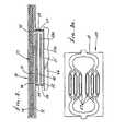
- FIG. 1shows a liquid cooler for an integrated circuit made of copper and containing a mesh for heat transfer from the liquid to the cooler walls.
- the cooleris soldered to a carbon-based water block containing vertically oriented grain.
- the coolantis injected centrally into the cooling chamber—in this case, using a centrifugal pump with a hollow shaft—and is driven towards the peripherally located outlet channels by the centrifugal rotor.
- the surface of the coolant chamberis machined to contain prismatic protrusions;
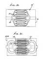
- FIG. 2 ashows a hierarchical channel system with opposite end intake and outflow as another embodiment of a carbon based liquid cooling block
- FIG. 2 bshows a different variation of a hierarchical fluid channel system
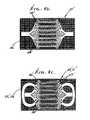
- FIG. 2 cshows an interleaved channel system in dual planes in which the channel-arrangement of the two planes is significant;
- FIG. 3shows the dual-plane carbon block attached to a copper cooler containing meshes for enhanced heat transfer.
- the carbon-based liquid cooling blockcomprises three plates, wherein the bottom and middle plates are machined to contain hierarchical channel systems. Alternatively, the top plate can be omitted for direct mounting of a composite channel liquid coolant block on the copper cooler;
- FIGS. 3 a and 3 bshow block plates, superimposed in FIG. 3 c .
- FIG. 4shows a dual-plane, interleaved channel, liquid cooling block integrated into a fully carbon-based cooler containing meshes for enhanced heat transfer.
- the grainis oriented preferentially in normal direction to the surface of the device to be cooled.
- FIGS. 4 a and 4 bshow carbon block plates superimposed in FIG. 4 c .
- a preferred waterblock 10is used in a sealed liquid cooling device 11 .
- the waterblockis typically manufactured from carbon with a preferred orientation of the ingrain of the block nanotubes extending substantially normal in direction to the surface 12 a of the semiconductor 12 to be cooled. Because thermal conductivity closely follows the orientation of the nanotubes, this orientation is advantageous for rapid removal of heat across the material. However, also because of the preferred direction of thermal conductivity in longitudinal alignment with the axial direction of the nanotubes, relatively little lateral spread of the thermal energy occurs. While this may appear disadvantageous for a conventional, passive cooling device, it allows concentration of the thermal release in sharply defined areas, which, in turn allows very effective heat removal through active fluid transport.
- the “outer” surface 10 a of the waterblock bottom plate 10 b that is in contact with the semiconductor 12 to be cooledis machined or formed to provide as much contact with the semiconductor as possible. Examples encompass mirror-polishing of both the top surface layer of the semiconductor and of the opposing bottom surface 10 a of the waterblock.
- the inner “surface” 10 c of the waterblock bottom plate 10 bis machined or formed to expose prism-like projections 14 extending into the fluid chamber 15 .
- these prismstypically have surfaces 14 a that form acute angles with their axial direction with only negligible loss in thermal conductance between the shortest and the longest parts of the prisms laterally.
- the surface area exposed to the cooling fluidis greatly increased and, moreover, the projections or extrusions cause coolant micro-turbulences in the fluid flowing generally radially as indicated by arrows 100 .
- Such micro-turbulencesprevent laminar flow of the coolant across the bottom of the chamber that would negatively affect the heat exchange between the block material chamber and the fluid.
- a pump indicated by rotor 18injects coolant to flow at 16 more or less into the center of the chamber from where it takes a centrifugal i.e. radial flow path or paths 100 across the prismatic bottom surface 10 c towards the periphery 19 and then into outflow axial channels 20 leading into a radiator 21 .
- the radiatoris preferably a micro mesh-based isothermal plate and mesh assembly 22 .
- the bottom plate 10 b ′can be a separate part of the assembly or part of the monolithic block 10 .
- the top surface of the carbon-based waterblockis plated at 24 to allow a soldered connection to copper- or aluminum-based radiator 21 . Coolant return flow is indicated by arrows 50 and 51 , in radiator 21 .
- a pump motor 26is located within 10 , and has a hollow shell 27 to pump flow 16 .
- a second embodiment of the carbon-based waterblockuses opposite-end orientation of the fluid intake and outlet as in FIG. 2 a .
- a primary intake 39or inlet channel, supplies fluid to the carbon water block 40 , inside of which it branches out at 40 a into a hierarchical system 40 b of several generations of daughter channels.
- the end branchesform a dense capillary network 40 c over the targeted surface opposed to the heat source, i.e. electric device.
- the capillary networkthen converges at 40 d in reverse order to a main outlet 41 , or outlet channel, that feeds into a radiator or heat exchanger as at 21 above, in the form of an isothermal plate.
- Such a channel systemis usable instead of, or supplementing, projections 14 .
- the top surface of the carbon-based waterblockis plated to allow for a soldered connection with a copper or aluminum-based radiator. See also FIGS. 2 b and 2 c configurations.
- a third embodiment of the inventionuses a waterblock in combination with an isothermal plate containing micro-channels wherein the entire cooling structure is manufactured from carbon.
- a pumpcan be integrated into the design or used as an external pump.
- a variation as seen in FIG. 3 of the second and third embodimentsuses two parallel planes of hierarchical water channels 50 ′ and 51 ′, in carbon block 54 which takes advantage of the fact that especially with carbon blocks containing primarily unidirectional grain, as indicated by vertical lines, heat conductivity is very little attenuated by increased layer thickness, at least within the range relevant for this invention.
- Two sets of separated coolant channelsare machined out of base plates 55 and 56 in a complementary pattern. That is, the branching coolant channels 57 in one plate overlap with the walls and branching channels 58 in the other plate, and vice versa as at 52 , 53 , 52 a and 53 a. See also FIG. 3 c .
- a heat conductive metal (such as copper) cooler 70fits over the carbon block 54 , as via a top carbon plate 71 , and receives heated fluid in channels 72 and 73 . Flow from block channels 57 and 58 passes at 74 into cooler lower channel 72 , and then to cooler upper channel 73 , and then edgewise through heat transfer mesh 77 , to return at 78 to parallel plane channels 57 and 58 .
- a highly compact efficient systemis thus provided.
- FIG. 4shows a similar dual-plane, interleaved channel, liquid cooling block 60 integrated into a fully carbon-based cooler that contains meshes 61 for enhanced heat transfer.
- the meshes 61 and channels 50 ′ and 51 ′are contained in the carbon block 60 .
- the die to be cooledis indicated at 66 .
- the grainis oriented preferentially in normal direction to the surface of the device to be cooled.
- Channels 57 ′ and 58 ′are like channels 57 and 58 , in block plates 55 ′ and 56 ′, like plates 55 and 56 .
- coolant flow pumpsmay be provided in series with channels shown; see also channel system details.
Landscapes
- Engineering & Computer Science (AREA)
- Physics & Mathematics (AREA)
- Thermal Sciences (AREA)
- Mechanical Engineering (AREA)
- General Engineering & Computer Science (AREA)
- Condensed Matter Physics & Semiconductors (AREA)
- General Physics & Mathematics (AREA)
- Computer Hardware Design (AREA)
- Microelectronics & Electronic Packaging (AREA)
- Power Engineering (AREA)
- Cooling Or The Like Of Semiconductors Or Solid State Devices (AREA)
- Cooling Or The Like Of Electrical Apparatus (AREA)
Abstract
Description
Claims (26)
Priority Applications (1)
| Application Number | Priority Date | Filing Date | Title |
|---|---|---|---|
| US12/012,654US8528628B2 (en) | 2007-02-08 | 2008-02-05 | Carbon-based apparatus for cooling of electronic devices |
Applications Claiming Priority (2)
| Application Number | Priority Date | Filing Date | Title |
|---|---|---|---|
| US90011107P | 2007-02-08 | 2007-02-08 | |
| US12/012,654US8528628B2 (en) | 2007-02-08 | 2008-02-05 | Carbon-based apparatus for cooling of electronic devices |
Publications (2)
| Publication Number | Publication Date |
|---|---|
| US20080190586A1 US20080190586A1 (en) | 2008-08-14 |
| US8528628B2true US8528628B2 (en) | 2013-09-10 |
Family
ID=39682309
Family Applications (1)
| Application Number | Title | Priority Date | Filing Date |
|---|---|---|---|
| US12/012,654Active2030-12-29US8528628B2 (en) | 2007-02-08 | 2008-02-05 | Carbon-based apparatus for cooling of electronic devices |
Country Status (2)
| Country | Link |
|---|---|
| US (1) | US8528628B2 (en) |
| WO (1) | WO2008097557A2 (en) |
Cited By (15)
| Publication number | Priority date | Publication date | Assignee | Title |
|---|---|---|---|---|
| US20130112377A1 (en)* | 2011-11-08 | 2013-05-09 | Industrial Technology Research Institute | Heat-dissipating device and heat-dissipating system |
| US20150007965A1 (en)* | 2013-07-05 | 2015-01-08 | Toyota Motor Engineerig & Manufacturing North America, Inc. | Cooling Assemblies Having Porous Three Dimensional Surfaces |
| WO2015095245A1 (en)* | 2013-12-16 | 2015-06-25 | KULR Technology Corporation | Carbon fiber heat exchangers |
| US20150359141A1 (en)* | 2014-06-06 | 2015-12-10 | Fujitsu Limited | Liquid-cooled jacket and electronic device |
| US9953899B2 (en) | 2015-09-30 | 2018-04-24 | Microfabrica Inc. | Micro heat transfer arrays, micro cold plates, and thermal management systems for cooling semiconductor devices, and methods for using and making such arrays, plates, and systems |
| US20180128153A1 (en)* | 2015-05-21 | 2018-05-10 | Brightron Co., Ltd | Cooling fan using surface cooling effect for rotating fan blade part |
| US10096537B1 (en) | 2015-12-31 | 2018-10-09 | Microfabrica Inc. | Thermal management systems, methods for making, and methods for using |
| US11209222B1 (en) | 2020-08-20 | 2021-12-28 | Hamilton Sundstrand Corporation | Spiral heat exchanger header |
| US11255534B2 (en)* | 2018-10-03 | 2022-02-22 | Coretronic Corporation | Thermal module and projector |
| US11268770B2 (en)* | 2019-09-06 | 2022-03-08 | Hamilton Sunstrand Corporation | Heat exchanger with radially converging manifold |
| US11274886B2 (en) | 2019-03-08 | 2022-03-15 | Hamilton Sundstrand Corporation | Heat exchanger header with fractal geometry |
| US11280550B2 (en)* | 2019-03-08 | 2022-03-22 | Hamilton Sundstrand Corporation | Radially layered helical core geometry for heat exchanger |
| US11359864B2 (en) | 2019-03-08 | 2022-06-14 | Hamilton Sundstrand Corporation | Rectangular helical core geometry for heat exchanger |
| US20220276008A1 (en)* | 2021-02-26 | 2022-09-01 | Teradyne, Inc. | Thermal plate having a fluid channel |
| US12255123B2 (en) | 2015-09-30 | 2025-03-18 | Microfabrica Inc. | Micro heat transfer arrays, micro cold plates, and thermal management systems for semiconductor devices, and methods for using and making such arrays, plates, and systems |
Families Citing this family (20)
| Publication number | Priority date | Publication date | Assignee | Title |
|---|---|---|---|---|
| US8561673B2 (en)* | 2006-09-26 | 2013-10-22 | Olantra Fund X L.L.C. | Sealed self-contained fluidic cooling device |
| US20090154091A1 (en) | 2007-12-17 | 2009-06-18 | Yatskov Alexander I | Cooling systems and heat exchangers for cooling computer components |
| US8170724B2 (en) | 2008-02-11 | 2012-05-01 | Cray Inc. | Systems and associated methods for controllably cooling computer components |
| KR101568421B1 (en) | 2009-05-04 | 2015-11-20 | 엘지전자 주식회사 | Air conditioning system |
| US20110186267A1 (en)* | 2010-02-01 | 2011-08-04 | Suna Display Co. | Heat transfer device with anisotropic thermal conducting micro structures |
| SE538960C2 (en)* | 2013-07-09 | 2017-03-07 | BAE Systems Hägglunds AB | Signature matching device and objects provided with signature matching device |
| DE102014202293A1 (en)* | 2014-02-07 | 2015-08-13 | Siemens Aktiengesellschaft | heatsink |
| CN105263301B (en)* | 2015-11-12 | 2017-12-19 | 深圳市研派科技有限公司 | A kind of liquid cooling heat radiation system and its liquid radiating row |
| US20190041104A1 (en)* | 2017-08-07 | 2019-02-07 | Asia Vital Components Co., Ltd. | Heat exchange structure of heat dissipation device |
| CN109890171A (en)* | 2017-12-06 | 2019-06-14 | 泽鸿(广州)电子科技有限公司 | Liquid cooling radiation module |
| US11121058B2 (en) | 2019-07-24 | 2021-09-14 | Aptiv Technologies Limited | Liquid cooled module with device heat spreader |
| US11751365B2 (en)* | 2019-10-29 | 2023-09-05 | Alliance For Sustainable Energy, Llc | Jet impingement manifolds for cooling power electronics modules |
| KR20220001196A (en)* | 2020-06-29 | 2022-01-05 | 에스케이하이닉스 주식회사 | Liquid cooling structure and liquid cooling system having the same |
| US11382205B2 (en) | 2020-09-16 | 2022-07-05 | Aptiv Technologies Limited | Heatsink shield with thermal-contact dimples for thermal-energy distribution in a radar assembly |
| CN113873849B (en)* | 2021-10-12 | 2022-10-11 | 西北工业大学 | An adaptively adjustable semi-submerged liquid-cooled cooling cavity, circulation system and application |
| CN116799479A (en)* | 2022-08-12 | 2023-09-22 | 中国航空无线电电子研究所 | Skin antenna subarray system with micro-channel structure |
| CN115548523B (en)* | 2022-09-30 | 2024-01-23 | 厦门海辰储能科技股份有限公司 | Battery cells, battery modules, battery packs and energy storage equipment |
| CN116666329B (en)* | 2023-04-28 | 2025-07-01 | 浙江大学杭州国际科创中心 | Cooling integrated gallium nitride module and preparation method thereof |
| US20240414881A1 (en)* | 2023-06-09 | 2024-12-12 | Carrier Corporation | Cooling system for power electronics |
| US20250071936A1 (en)* | 2023-08-23 | 2025-02-27 | Hrl Laboratories, Llc | Microchannel cooling block and cooling system including the same |
Citations (57)
| Publication number | Priority date | Publication date | Assignee | Title |
|---|---|---|---|---|
| US4109707A (en) | 1975-07-02 | 1978-08-29 | Honeywell Information Systems, Inc. | Fluid cooling systems for electronic systems |
| US4165733A (en)* | 1977-03-31 | 1979-08-28 | Olin Corporation | Solar energy collector system |
| US4392362A (en)* | 1979-03-23 | 1983-07-12 | The Board Of Trustees Of The Leland Stanford Junior University | Micro miniature refrigerators |
| US4450472A (en) | 1981-03-02 | 1984-05-22 | The Board Of Trustees Of The Leland Stanford Junior University | Method and means for improved heat removal in compact semiconductor integrated circuits and similar devices utilizing coolant chambers and microscopic channels |
| US5361828A (en) | 1993-02-17 | 1994-11-08 | General Electric Company | Scaled heat transfer surface with protruding ramp surface turbulators |
| US5388635A (en)* | 1990-04-27 | 1995-02-14 | International Business Machines Corporation | Compliant fluidic coolant hat |
| US5542471A (en)* | 1993-11-16 | 1996-08-06 | Loral Vought System Corporation | Heat transfer element having the thermally conductive fibers |
| US5628363A (en) | 1995-04-13 | 1997-05-13 | Alliedsignal Inc. | Composite continuous sheet fin heat exchanger |
| US5801442A (en) | 1996-07-22 | 1998-09-01 | Northrop Grumman Corporation | Microchannel cooling of high power semiconductor devices |
| US5998863A (en) | 1996-07-19 | 1999-12-07 | Denso Corporation | Cooling apparatus boiling and condensing refrigerant |
| US6301109B1 (en) | 2000-02-11 | 2001-10-09 | International Business Machines Corporation | Isothermal heat sink with cross-flow openings between channels |
| US20020011330A1 (en)* | 1998-06-18 | 2002-01-31 | Thomas I. Insley | Microchanneled active fluid heat exchanger |
| US20030077449A1 (en)* | 2000-02-25 | 2003-04-24 | Jing-Wen Tzeng | Thermal management system |
| US6668911B2 (en) | 2002-05-08 | 2003-12-30 | Itt Manufacturing Enterprises, Inc. | Pump system for use in a heat exchange application |
| US6672502B1 (en) | 2000-11-28 | 2004-01-06 | The State Of Oregon Acting By And Through The State Board Of Higher Education On Behalf Of Oregon State University | Method for making devices having intermetallic structures and intermetallic devices made thereby |
| US6675875B1 (en) | 1999-08-06 | 2004-01-13 | The Ohio State University | Multi-layered micro-channel heat sink, devices and systems incorporating same |
| US20040011511A1 (en) | 2002-07-18 | 2004-01-22 | Debashis Ghosh | Thermosiphon for electronics cooling with nonuniform airflow |
| US6692700B2 (en) | 2001-02-14 | 2004-02-17 | Handylab, Inc. | Heat-reduction methods and systems related to microfluidic devices |
| US20040052048A1 (en) | 2002-09-13 | 2004-03-18 | Wu Bo Jiu | Integrated fluid cooling system for electronic components |
| US6736195B2 (en) | 2000-06-15 | 2004-05-18 | Borgwarner Inc. | Cooling fin arrangement |
| US6785134B2 (en) | 2003-01-06 | 2004-08-31 | Intel Corporation | Embedded liquid pump and microchannel cooling system |
| US6793831B1 (en) | 1998-08-06 | 2004-09-21 | State Of Oregon Acting By And Through The State Board Of Higher Education On Behalf Of Oregon State University | Microlamination method for making devices |
| US6812563B2 (en) | 2001-07-19 | 2004-11-02 | Samsung Electronics Co., Ltd. | Microcooling device |
| US6844054B2 (en)* | 2001-04-30 | 2005-01-18 | Thermo Composite, Llc | Thermal management material, devices and methods therefor |
| US6865081B2 (en)* | 2002-10-02 | 2005-03-08 | Atotech Deutschland Gmbh | Microstructure cooler and use thereof |
| US6889756B1 (en)* | 2004-04-06 | 2005-05-10 | Epos Inc. | High efficiency isothermal heat sink |
| US6894899B2 (en) | 2002-09-13 | 2005-05-17 | Hong Kong Cheung Tat Electrical Co. Ltd. | Integrated fluid cooling system for electronic components |
| US20050116336A1 (en) | 2003-09-16 | 2005-06-02 | Koila, Inc. | Nano-composite materials for thermal management applications |
| US6903929B2 (en)* | 2003-03-31 | 2005-06-07 | Intel Corporation | Two-phase cooling utilizing microchannel heat exchangers and channeled heat sink |
| US6904966B2 (en) | 2002-05-20 | 2005-06-14 | The Board Of Trustees Of The University Of Illinois | Flexible microchannel heat exchanger |
| US20050162833A1 (en) | 2001-09-27 | 2005-07-28 | International Business Machines Corporation | Transpiration cooled heat sink and a self contained coolant supply for same |
| US20050175838A1 (en) | 2001-12-26 | 2005-08-11 | Greinke Ronald A. | Thermal interface material |
| US6942015B1 (en) | 2000-10-05 | 2005-09-13 | Jenkins Comfort Systems, Llc | Body heating/cooling apparatus |
| US20050257917A1 (en) | 2004-04-02 | 2005-11-24 | Par Technologies, Llc. | Thermal transfer devices with fluid-porous thermally conductive core |
| US6989134B2 (en) | 2002-11-27 | 2006-01-24 | Velocys Inc. | Microchannel apparatus, methods of making microchannel apparatus, and processes of conducting unit operations |
| US6991024B2 (en) | 2001-09-28 | 2006-01-31 | The Board Of Trustees Of The Leland Stanford Junior University | Electroosmotic microchannel cooling system |
| US6992382B2 (en) | 2003-12-29 | 2006-01-31 | Intel Corporation | Integrated micro channels and manifold/plenum using separate silicon or low-cost polycrystalline silicon |
| US7000684B2 (en) | 2002-11-01 | 2006-02-21 | Cooligy, Inc. | Method and apparatus for efficient vertical fluid delivery for cooling a heat producing device |
| US20060090885A1 (en) | 2004-10-29 | 2006-05-04 | Stephen Montgomery | Thermally conductive channel between a semiconductor chip and an external thermal interface |
| US7048723B1 (en) | 1998-09-18 | 2006-05-23 | The University Of Utah Research Foundation | Surface micromachined microneedles |
| US20060137856A1 (en)* | 2004-12-23 | 2006-06-29 | Ch Capital, Inc. Aka Ch Capital, Llc | Cooling systems incorporating heat transfer meshes |
| US20060162903A1 (en) | 2005-01-21 | 2006-07-27 | Bhatti Mohinder S | Liquid cooled thermosiphon with flexible partition |
| US20060162904A1 (en) | 2005-01-21 | 2006-07-27 | Bhatti Mohinder S | Liquid cooled thermosiphon for electronic components |
| US20060171801A1 (en)* | 2004-12-27 | 2006-08-03 | Matsushita Electric Industrial Co., Ltd. | Heatsink apparatus |
| US20060180300A1 (en) | 2003-07-23 | 2006-08-17 | Lenehan Daniel J | Pump and fan control concepts in a cooling system |
| US20060191667A1 (en) | 2005-02-25 | 2006-08-31 | Delta Electronics, Inc. | Liquid-cooled heat dissipation module |
| US7115987B2 (en)* | 2003-12-31 | 2006-10-03 | Intel Corporation | Integrated stacked microchannel heat exchanger and heat spreader |
| US20070034356A1 (en)* | 2002-11-01 | 2007-02-15 | Cooligy, Inc. | Cooling systems incorporating heat exchangers and thermoelectric layers |
| US20070116957A1 (en) | 2005-05-11 | 2007-05-24 | Molecular Nanosystems, Inc. | Carbon nanotube thermal pads |
| US7246655B2 (en) | 2004-12-17 | 2007-07-24 | Fujikura Ltd. | Heat transfer device |
| US20070227701A1 (en) | 2006-03-31 | 2007-10-04 | Bhatti Mohinder S | Thermosiphon with flexible boiler plate |
| US20070272392A1 (en) | 2006-05-23 | 2007-11-29 | Debashis Ghosh | Impingement cooled heat sink with low pressure drop |
| US7333336B2 (en) | 2004-10-20 | 2008-02-19 | Lg Electronics Inc. | Heat radiating apparatus |
| US7414843B2 (en)* | 2004-03-10 | 2008-08-19 | Intel Corporation | Method and apparatus for a layered thermal management arrangement |
| US7424906B2 (en) | 2006-04-19 | 2008-09-16 | Delphi Technologies, Inc. | High performance thermosiphon with internally enhanced condensation |
| US7477517B2 (en)* | 2007-01-29 | 2009-01-13 | International Business Machines Corporation | Integrated heat spreader and exchanger |
| US8037927B2 (en) | 2006-11-16 | 2011-10-18 | CUI Global, Inc. | Cooling device for an electronic component |
Family Cites Families (4)
| Publication number | Priority date | Publication date | Assignee | Title |
|---|---|---|---|---|
| US6019165A (en)* | 1998-05-18 | 2000-02-01 | Batchelder; John Samuel | Heat exchange apparatus |
| WO2001095688A1 (en)* | 2000-06-05 | 2001-12-13 | The State Of Oregon Acting By And Through The State Board Of Higher Education On Behalf Of The University Of Oregon | Multiscale transport apparatus and methods |
| DE10319367A1 (en)* | 2003-04-29 | 2004-11-25 | Fraunhofer-Gesellschaft zur Förderung der angewandten Forschung e.V. | Process for creating a hydraulic network for optimized heat transfer and mass transfer |
| US20060231238A1 (en)* | 2005-04-13 | 2006-10-19 | Par Technologies, Llc | Integrated thermal exchange systems and methods of fabricating same |
- 2008
- 2008-02-05USUS12/012,654patent/US8528628B2/enactiveActive
- 2008-02-06WOPCT/US2008/001540patent/WO2008097557A2/enactiveApplication Filing
Patent Citations (59)
| Publication number | Priority date | Publication date | Assignee | Title |
|---|---|---|---|---|
| US4109707A (en) | 1975-07-02 | 1978-08-29 | Honeywell Information Systems, Inc. | Fluid cooling systems for electronic systems |
| US4165733A (en)* | 1977-03-31 | 1979-08-28 | Olin Corporation | Solar energy collector system |
| US4392362A (en)* | 1979-03-23 | 1983-07-12 | The Board Of Trustees Of The Leland Stanford Junior University | Micro miniature refrigerators |
| US4450472A (en) | 1981-03-02 | 1984-05-22 | The Board Of Trustees Of The Leland Stanford Junior University | Method and means for improved heat removal in compact semiconductor integrated circuits and similar devices utilizing coolant chambers and microscopic channels |
| US5388635A (en)* | 1990-04-27 | 1995-02-14 | International Business Machines Corporation | Compliant fluidic coolant hat |
| US5361828A (en) | 1993-02-17 | 1994-11-08 | General Electric Company | Scaled heat transfer surface with protruding ramp surface turbulators |
| US5542471A (en)* | 1993-11-16 | 1996-08-06 | Loral Vought System Corporation | Heat transfer element having the thermally conductive fibers |
| US5628363A (en) | 1995-04-13 | 1997-05-13 | Alliedsignal Inc. | Composite continuous sheet fin heat exchanger |
| US5998863A (en) | 1996-07-19 | 1999-12-07 | Denso Corporation | Cooling apparatus boiling and condensing refrigerant |
| US5801442A (en) | 1996-07-22 | 1998-09-01 | Northrop Grumman Corporation | Microchannel cooling of high power semiconductor devices |
| US20020011330A1 (en)* | 1998-06-18 | 2002-01-31 | Thomas I. Insley | Microchanneled active fluid heat exchanger |
| US6793831B1 (en) | 1998-08-06 | 2004-09-21 | State Of Oregon Acting By And Through The State Board Of Higher Education On Behalf Of Oregon State University | Microlamination method for making devices |
| US7048723B1 (en) | 1998-09-18 | 2006-05-23 | The University Of Utah Research Foundation | Surface micromachined microneedles |
| US6675875B1 (en) | 1999-08-06 | 2004-01-13 | The Ohio State University | Multi-layered micro-channel heat sink, devices and systems incorporating same |
| US6301109B1 (en) | 2000-02-11 | 2001-10-09 | International Business Machines Corporation | Isothermal heat sink with cross-flow openings between channels |
| US20030077449A1 (en)* | 2000-02-25 | 2003-04-24 | Jing-Wen Tzeng | Thermal management system |
| US6736195B2 (en) | 2000-06-15 | 2004-05-18 | Borgwarner Inc. | Cooling fin arrangement |
| US6942015B1 (en) | 2000-10-05 | 2005-09-13 | Jenkins Comfort Systems, Llc | Body heating/cooling apparatus |
| US6672502B1 (en) | 2000-11-28 | 2004-01-06 | The State Of Oregon Acting By And Through The State Board Of Higher Education On Behalf Of Oregon State University | Method for making devices having intermetallic structures and intermetallic devices made thereby |
| US6692700B2 (en) | 2001-02-14 | 2004-02-17 | Handylab, Inc. | Heat-reduction methods and systems related to microfluidic devices |
| US6844054B2 (en)* | 2001-04-30 | 2005-01-18 | Thermo Composite, Llc | Thermal management material, devices and methods therefor |
| US6812563B2 (en) | 2001-07-19 | 2004-11-02 | Samsung Electronics Co., Ltd. | Microcooling device |
| US20050162833A1 (en) | 2001-09-27 | 2005-07-28 | International Business Machines Corporation | Transpiration cooled heat sink and a self contained coolant supply for same |
| US6991024B2 (en) | 2001-09-28 | 2006-01-31 | The Board Of Trustees Of The Leland Stanford Junior University | Electroosmotic microchannel cooling system |
| US20050175838A1 (en) | 2001-12-26 | 2005-08-11 | Greinke Ronald A. | Thermal interface material |
| US6668911B2 (en) | 2002-05-08 | 2003-12-30 | Itt Manufacturing Enterprises, Inc. | Pump system for use in a heat exchange application |
| US6904966B2 (en) | 2002-05-20 | 2005-06-14 | The Board Of Trustees Of The University Of Illinois | Flexible microchannel heat exchanger |
| US20040011511A1 (en) | 2002-07-18 | 2004-01-22 | Debashis Ghosh | Thermosiphon for electronics cooling with nonuniform airflow |
| US6894899B2 (en) | 2002-09-13 | 2005-05-17 | Hong Kong Cheung Tat Electrical Co. Ltd. | Integrated fluid cooling system for electronic components |
| US20040052048A1 (en) | 2002-09-13 | 2004-03-18 | Wu Bo Jiu | Integrated fluid cooling system for electronic components |
| US6865081B2 (en)* | 2002-10-02 | 2005-03-08 | Atotech Deutschland Gmbh | Microstructure cooler and use thereof |
| US20070034356A1 (en)* | 2002-11-01 | 2007-02-15 | Cooligy, Inc. | Cooling systems incorporating heat exchangers and thermoelectric layers |
| US7000684B2 (en) | 2002-11-01 | 2006-02-21 | Cooligy, Inc. | Method and apparatus for efficient vertical fluid delivery for cooling a heat producing device |
| US6989134B2 (en) | 2002-11-27 | 2006-01-24 | Velocys Inc. | Microchannel apparatus, methods of making microchannel apparatus, and processes of conducting unit operations |
| US6785134B2 (en) | 2003-01-06 | 2004-08-31 | Intel Corporation | Embedded liquid pump and microchannel cooling system |
| US6903929B2 (en)* | 2003-03-31 | 2005-06-07 | Intel Corporation | Two-phase cooling utilizing microchannel heat exchangers and channeled heat sink |
| US20060180300A1 (en) | 2003-07-23 | 2006-08-17 | Lenehan Daniel J | Pump and fan control concepts in a cooling system |
| US20050116336A1 (en) | 2003-09-16 | 2005-06-02 | Koila, Inc. | Nano-composite materials for thermal management applications |
| US6992382B2 (en) | 2003-12-29 | 2006-01-31 | Intel Corporation | Integrated micro channels and manifold/plenum using separate silicon or low-cost polycrystalline silicon |
| US7115987B2 (en)* | 2003-12-31 | 2006-10-03 | Intel Corporation | Integrated stacked microchannel heat exchanger and heat spreader |
| US7414843B2 (en)* | 2004-03-10 | 2008-08-19 | Intel Corporation | Method and apparatus for a layered thermal management arrangement |
| US20050257917A1 (en) | 2004-04-02 | 2005-11-24 | Par Technologies, Llc. | Thermal transfer devices with fluid-porous thermally conductive core |
| US6889756B1 (en)* | 2004-04-06 | 2005-05-10 | Epos Inc. | High efficiency isothermal heat sink |
| US7333336B2 (en) | 2004-10-20 | 2008-02-19 | Lg Electronics Inc. | Heat radiating apparatus |
| US20060090885A1 (en) | 2004-10-29 | 2006-05-04 | Stephen Montgomery | Thermally conductive channel between a semiconductor chip and an external thermal interface |
| US7246655B2 (en) | 2004-12-17 | 2007-07-24 | Fujikura Ltd. | Heat transfer device |
| US7694722B2 (en) | 2004-12-23 | 2010-04-13 | Onscreen Technologies, Inc. | Cooling systems incorporating heat transfer meshes |
| US7599626B2 (en) | 2004-12-23 | 2009-10-06 | Waytronx, Inc. | Communication systems incorporating control meshes |
| US20060137856A1 (en)* | 2004-12-23 | 2006-06-29 | Ch Capital, Inc. Aka Ch Capital, Llc | Cooling systems incorporating heat transfer meshes |
| US20060171801A1 (en)* | 2004-12-27 | 2006-08-03 | Matsushita Electric Industrial Co., Ltd. | Heatsink apparatus |
| US20060162903A1 (en) | 2005-01-21 | 2006-07-27 | Bhatti Mohinder S | Liquid cooled thermosiphon with flexible partition |
| US20060162904A1 (en) | 2005-01-21 | 2006-07-27 | Bhatti Mohinder S | Liquid cooled thermosiphon for electronic components |
| US20060191667A1 (en) | 2005-02-25 | 2006-08-31 | Delta Electronics, Inc. | Liquid-cooled heat dissipation module |
| US20070116957A1 (en) | 2005-05-11 | 2007-05-24 | Molecular Nanosystems, Inc. | Carbon nanotube thermal pads |
| US20070227701A1 (en) | 2006-03-31 | 2007-10-04 | Bhatti Mohinder S | Thermosiphon with flexible boiler plate |
| US7424906B2 (en) | 2006-04-19 | 2008-09-16 | Delphi Technologies, Inc. | High performance thermosiphon with internally enhanced condensation |
| US20070272392A1 (en) | 2006-05-23 | 2007-11-29 | Debashis Ghosh | Impingement cooled heat sink with low pressure drop |
| US8037927B2 (en) | 2006-11-16 | 2011-10-18 | CUI Global, Inc. | Cooling device for an electronic component |
| US7477517B2 (en)* | 2007-01-29 | 2009-01-13 | International Business Machines Corporation | Integrated heat spreader and exchanger |
Non-Patent Citations (2)
| Title |
|---|
| Che Jianwei, et al., (Thermal Conductivity of Carbon Nanotubes), Mar. 2, 2000, Nanotechnology, 11, 65-69). |
| Che Jianwei, et al., (Thermal Conductivity of Carbon Nanotubes, Mar. 2, 2000, Nanotechnology, 11, 65-69) discloses thermal conductivity across and along grain boundaries for structures composed substantially of carbon.* |
Cited By (21)
| Publication number | Priority date | Publication date | Assignee | Title |
|---|---|---|---|---|
| US20130112377A1 (en)* | 2011-11-08 | 2013-05-09 | Industrial Technology Research Institute | Heat-dissipating device and heat-dissipating system |
| US20150007965A1 (en)* | 2013-07-05 | 2015-01-08 | Toyota Motor Engineerig & Manufacturing North America, Inc. | Cooling Assemblies Having Porous Three Dimensional Surfaces |
| US9803938B2 (en)* | 2013-07-05 | 2017-10-31 | Toyota Motor Engineering & Manufacturing North America, Inc. | Cooling assemblies having porous three dimensional surfaces |
| WO2015095245A1 (en)* | 2013-12-16 | 2015-06-25 | KULR Technology Corporation | Carbon fiber heat exchangers |
| US20150359141A1 (en)* | 2014-06-06 | 2015-12-10 | Fujitsu Limited | Liquid-cooled jacket and electronic device |
| US20180128153A1 (en)* | 2015-05-21 | 2018-05-10 | Brightron Co., Ltd | Cooling fan using surface cooling effect for rotating fan blade part |
| US9953899B2 (en) | 2015-09-30 | 2018-04-24 | Microfabrica Inc. | Micro heat transfer arrays, micro cold plates, and thermal management systems for cooling semiconductor devices, and methods for using and making such arrays, plates, and systems |
| US10665530B2 (en) | 2015-09-30 | 2020-05-26 | Microfabrica Inc. | Micro heat transfer arrays, micro cold plates, and thermal management systems for cooling semiconductor devices, and methods for using and making such arrays, plates, and systems |
| US10957624B2 (en) | 2015-09-30 | 2021-03-23 | Microfabrica Inc. | Micro heat transfer arrays, micro cold plates, and thermal management systems for cooling semiconductor devices, and methods for using and making such arrays, plates, and systems |
| US12255123B2 (en) | 2015-09-30 | 2025-03-18 | Microfabrica Inc. | Micro heat transfer arrays, micro cold plates, and thermal management systems for semiconductor devices, and methods for using and making such arrays, plates, and systems |
| US11456235B1 (en) | 2015-09-30 | 2022-09-27 | Microfabrica Inc. | Micro heat transfer arrays, micro cold plates, and thermal management systems for cooling semiconductor devices, and methods for using and making such arrays, plates, and systems |
| US10096537B1 (en) | 2015-12-31 | 2018-10-09 | Microfabrica Inc. | Thermal management systems, methods for making, and methods for using |
| US11255534B2 (en)* | 2018-10-03 | 2022-02-22 | Coretronic Corporation | Thermal module and projector |
| US11359864B2 (en) | 2019-03-08 | 2022-06-14 | Hamilton Sundstrand Corporation | Rectangular helical core geometry for heat exchanger |
| US11280550B2 (en)* | 2019-03-08 | 2022-03-22 | Hamilton Sundstrand Corporation | Radially layered helical core geometry for heat exchanger |
| US11274886B2 (en) | 2019-03-08 | 2022-03-15 | Hamilton Sundstrand Corporation | Heat exchanger header with fractal geometry |
| US11268770B2 (en)* | 2019-09-06 | 2022-03-08 | Hamilton Sunstrand Corporation | Heat exchanger with radially converging manifold |
| US12130090B2 (en) | 2019-09-06 | 2024-10-29 | Hamilton Sundstrand Corporation | Heat exchanger with radially converging manifold |
| US11209222B1 (en) | 2020-08-20 | 2021-12-28 | Hamilton Sundstrand Corporation | Spiral heat exchanger header |
| US20220276008A1 (en)* | 2021-02-26 | 2022-09-01 | Teradyne, Inc. | Thermal plate having a fluid channel |
| US12287151B2 (en)* | 2021-02-26 | 2025-04-29 | Teradyne, Inc. | Thermal plate having a fluid channel |
Also Published As
| Publication number | Publication date |
|---|---|
| WO2008097557A2 (en) | 2008-08-14 |
| WO2008097557B1 (en) | 2008-12-18 |
| US20080190586A1 (en) | 2008-08-14 |
| WO2008097557A3 (en) | 2008-11-06 |
Similar Documents
| Publication | Publication Date | Title |
|---|---|---|
| US8528628B2 (en) | Carbon-based apparatus for cooling of electronic devices | |
| US8037927B2 (en) | Cooling device for an electronic component | |
| US6988534B2 (en) | Method and apparatus for flexible fluid delivery for cooling desired hot spots in a heat producing device | |
| US8464781B2 (en) | Cooling systems incorporating heat exchangers and thermoelectric layers | |
| US6986382B2 (en) | Interwoven manifolds for pressure drop reduction in microchannel heat exchangers | |
| US7697291B2 (en) | Active liquid metal thermal spreader | |
| US7836597B2 (en) | Method of fabricating high surface to volume ratio structures and their integration in microheat exchangers for liquid cooling system | |
| JP5523542B1 (en) | Cooling system | |
| JP6164304B2 (en) | Manufacturing method of semiconductor module cooler, semiconductor module cooler, semiconductor module, and electrically driven vehicle | |
| JP5801996B2 (en) | Double-sided cooling power module with power coating | |
| JP3202014B2 (en) | Micro cooling device | |
| US8561673B2 (en) | Sealed self-contained fluidic cooling device | |
| US20050211418A1 (en) | Method and apparatus for efficient vertical fluid delivery for cooling a heat producing device | |
| US20040112571A1 (en) | Method and apparatus for efficient vertical fluid delivery for cooling a heat producing device | |
| US20040206477A1 (en) | Method and apparatus for efficient vertical fluid delivery for cooling a heat producing device | |
| US9557118B2 (en) | Cooling technique | |
| US20050211417A1 (en) | Interwoven manifolds for pressure drop reduction in microchannel heat exchangers | |
| US20100065255A1 (en) | Vapor Chamber | |
| US20050211427A1 (en) | Method and apparatus for flexible fluid delivery for cooling desired hot spots in a heat producing device | |
| US20130032311A1 (en) | System for Using Active and Passive Cooling for High Power Thermal Management | |
| KR20040050910A (en) | High heat flux single-phase heat exchanger | |
| US20060131003A1 (en) | Apparatus and associated method for microelectronic cooling | |
| JP2008111653A (en) | Cooler | |
| CN109890177A (en) | An electronic device thermal management microstructure | |
| JP2008509550A (en) | Electronic board cooling system |
Legal Events
| Date | Code | Title | Description |
|---|---|---|---|
| AS | Assignment | Owner name:ONSCREEN TECHNOLOGIES, INC., OREGON Free format text:ASSIGNMENT OF ASSIGNORS INTEREST;ASSIGNOR:ROBINSON, STANLEY;REEL/FRAME:020494/0013 Effective date:20080131 | |
| AS | Assignment | Owner name:WAYTRONX, INC., OREGON Free format text:CHANGE OF NAME;ASSIGNOR:ONSCREEN TECHNOLOGIES, INC.;REEL/FRAME:027520/0160 Effective date:20071210 | |
| AS | Assignment | Owner name:CUI GLOBAL, INC., OREGON Free format text:CHANGE OF NAME;ASSIGNOR:WAYTRONX, INC.;REEL/FRAME:027556/0069 Effective date:20101202 | |
| AS | Assignment | Owner name:OLANTRA FUND X L.L.C., DELAWARE Free format text:ASSIGNMENT OF ASSIGNORS INTEREST;ASSIGNOR:CUI GLOBAL, INC.;REEL/FRAME:027569/0070 Effective date:20111128 | |
| STCF | Information on status: patent grant | Free format text:PATENTED CASE | |
| AS | Assignment | Owner name:NYTELL SOFTWARE LLC, DELAWARE Free format text:MERGER;ASSIGNOR:OLANTRA FUND X L.L.C.;REEL/FRAME:037392/0788 Effective date:20150826 | |
| FPAY | Fee payment | Year of fee payment:4 | |
| MAFP | Maintenance fee payment | Free format text:PAYMENT OF MAINTENANCE FEE, 8TH YEAR, LARGE ENTITY (ORIGINAL EVENT CODE: M1552); ENTITY STATUS OF PATENT OWNER: LARGE ENTITY Year of fee payment:8 | |
| MAFP | Maintenance fee payment | Free format text:PAYMENT OF MAINTENANCE FEE, 12TH YEAR, LARGE ENTITY (ORIGINAL EVENT CODE: M1553); ENTITY STATUS OF PATENT OWNER: LARGE ENTITY Year of fee payment:12 |