US8528563B2 - Systems, methods and devices for performing gynecological procedures - Google Patents
Systems, methods and devices for performing gynecological proceduresDownload PDFInfo
- Publication number
- US8528563B2 US8528563B2US12/098,224US9822408AUS8528563B2US 8528563 B2US8528563 B2US 8528563B2US 9822408 AUS9822408 AUS 9822408AUS 8528563 B2US8528563 B2US 8528563B2
- Authority
- US
- United States
- Prior art keywords
- fallopian tube
- tissue
- arms
- balloon
- devices
- Prior art date
- Legal status (The legal status is an assumption and is not a legal conclusion. Google has not performed a legal analysis and makes no representation as to the accuracy of the status listed.)
- Active, expires
Links
Images


Classifications
- A—HUMAN NECESSITIES
- A61—MEDICAL OR VETERINARY SCIENCE; HYGIENE
- A61B—DIAGNOSIS; SURGERY; IDENTIFICATION
- A61B1/00—Instruments for performing medical examinations of the interior of cavities or tubes of the body by visual or photographical inspection, e.g. endoscopes; Illuminating arrangements therefor
- A61B1/303—Instruments for performing medical examinations of the interior of cavities or tubes of the body by visual or photographical inspection, e.g. endoscopes; Illuminating arrangements therefor for the vagina, i.e. vaginoscopes
- A—HUMAN NECESSITIES
- A61—MEDICAL OR VETERINARY SCIENCE; HYGIENE
- A61B—DIAGNOSIS; SURGERY; IDENTIFICATION
- A61B17/00—Surgical instruments, devices or methods
- A61B17/42—Gynaecological or obstetrical instruments or methods
- A61B17/4241—Instruments for manoeuvring or retracting the uterus, e.g. during laparoscopic surgery
- A—HUMAN NECESSITIES
- A61—MEDICAL OR VETERINARY SCIENCE; HYGIENE
- A61B—DIAGNOSIS; SURGERY; IDENTIFICATION
- A61B1/00—Instruments for performing medical examinations of the interior of cavities or tubes of the body by visual or photographical inspection, e.g. endoscopes; Illuminating arrangements therefor
- A61B1/06—Instruments for performing medical examinations of the interior of cavities or tubes of the body by visual or photographical inspection, e.g. endoscopes; Illuminating arrangements therefor with illuminating arrangements
- A61B1/0615—Instruments for performing medical examinations of the interior of cavities or tubes of the body by visual or photographical inspection, e.g. endoscopes; Illuminating arrangements therefor with illuminating arrangements for radial illumination
- A—HUMAN NECESSITIES
- A61—MEDICAL OR VETERINARY SCIENCE; HYGIENE
- A61B—DIAGNOSIS; SURGERY; IDENTIFICATION
- A61B1/00—Instruments for performing medical examinations of the interior of cavities or tubes of the body by visual or photographical inspection, e.g. endoscopes; Illuminating arrangements therefor
- A61B1/06—Instruments for performing medical examinations of the interior of cavities or tubes of the body by visual or photographical inspection, e.g. endoscopes; Illuminating arrangements therefor with illuminating arrangements
- A61B1/0661—Endoscope light sources
- A—HUMAN NECESSITIES
- A61—MEDICAL OR VETERINARY SCIENCE; HYGIENE
- A61B—DIAGNOSIS; SURGERY; IDENTIFICATION
- A61B17/00—Surgical instruments, devices or methods
- A61B17/02—Surgical instruments, devices or methods for holding wounds open, e.g. retractors; Tractors
- A—HUMAN NECESSITIES
- A61—MEDICAL OR VETERINARY SCIENCE; HYGIENE
- A61B—DIAGNOSIS; SURGERY; IDENTIFICATION
- A61B17/00—Surgical instruments, devices or methods
- A61B17/02—Surgical instruments, devices or methods for holding wounds open, e.g. retractors; Tractors
- A61B17/0218—Surgical instruments, devices or methods for holding wounds open, e.g. retractors; Tractors for minimally invasive surgery
- A—HUMAN NECESSITIES
- A61—MEDICAL OR VETERINARY SCIENCE; HYGIENE
- A61B—DIAGNOSIS; SURGERY; IDENTIFICATION
- A61B17/00—Surgical instruments, devices or methods
- A61B17/12—Surgical instruments, devices or methods for ligaturing or otherwise compressing tubular parts of the body, e.g. blood vessels or umbilical cord
- A61B17/12022—Occluding by internal devices, e.g. balloons or releasable wires
- A61B17/12027—Type of occlusion
- A61B17/1204—Type of occlusion temporary occlusion
- A61B17/12045—Type of occlusion temporary occlusion double occlusion, e.g. during anastomosis
- A—HUMAN NECESSITIES
- A61—MEDICAL OR VETERINARY SCIENCE; HYGIENE
- A61B—DIAGNOSIS; SURGERY; IDENTIFICATION
- A61B17/00—Surgical instruments, devices or methods
- A61B17/12—Surgical instruments, devices or methods for ligaturing or otherwise compressing tubular parts of the body, e.g. blood vessels or umbilical cord
- A61B17/12022—Occluding by internal devices, e.g. balloons or releasable wires
- A61B17/12099—Occluding by internal devices, e.g. balloons or releasable wires characterised by the location of the occluder
- A—HUMAN NECESSITIES
- A61—MEDICAL OR VETERINARY SCIENCE; HYGIENE
- A61B—DIAGNOSIS; SURGERY; IDENTIFICATION
- A61B17/00—Surgical instruments, devices or methods
- A61B17/12—Surgical instruments, devices or methods for ligaturing or otherwise compressing tubular parts of the body, e.g. blood vessels or umbilical cord
- A61B17/12022—Occluding by internal devices, e.g. balloons or releasable wires
- A61B17/12131—Occluding by internal devices, e.g. balloons or releasable wires characterised by the type of occluding device
- A61B17/12136—Balloons
- A—HUMAN NECESSITIES
- A61—MEDICAL OR VETERINARY SCIENCE; HYGIENE
- A61B—DIAGNOSIS; SURGERY; IDENTIFICATION
- A61B17/00—Surgical instruments, devices or methods
- A61B17/22—Implements for squeezing-off ulcers or the like on inner organs of the body; Implements for scraping-out cavities of body organs, e.g. bones; for invasive removal or destruction of calculus using mechanical vibrations; for removing obstructions in blood vessels, not otherwise provided for
- A—HUMAN NECESSITIES
- A61—MEDICAL OR VETERINARY SCIENCE; HYGIENE
- A61B—DIAGNOSIS; SURGERY; IDENTIFICATION
- A61B17/00—Surgical instruments, devices or methods
- A61B17/30—Surgical pincettes, i.e. surgical tweezers without pivotal connections
- A—HUMAN NECESSITIES
- A61—MEDICAL OR VETERINARY SCIENCE; HYGIENE
- A61B—DIAGNOSIS; SURGERY; IDENTIFICATION
- A61B17/00—Surgical instruments, devices or methods
- A61B17/32—Surgical cutting instruments
- A61B17/320016—Endoscopic cutting instruments, e.g. arthroscopes, resectoscopes
- A61B17/32002—Endoscopic cutting instruments, e.g. arthroscopes, resectoscopes with continuously rotating, oscillating or reciprocating cutting instruments
- A—HUMAN NECESSITIES
- A61—MEDICAL OR VETERINARY SCIENCE; HYGIENE
- A61B—DIAGNOSIS; SURGERY; IDENTIFICATION
- A61B17/00—Surgical instruments, devices or methods
- A61B17/42—Gynaecological or obstetrical instruments or methods
- A—HUMAN NECESSITIES
- A61—MEDICAL OR VETERINARY SCIENCE; HYGIENE
- A61B—DIAGNOSIS; SURGERY; IDENTIFICATION
- A61B5/00—Measuring for diagnostic purposes; Identification of persons
- A61B5/68—Arrangements of detecting, measuring or recording means, e.g. sensors, in relation to patient
- A61B5/6846—Arrangements of detecting, measuring or recording means, e.g. sensors, in relation to patient specially adapted to be brought in contact with an internal body part, i.e. invasive
- A61B5/6867—Arrangements of detecting, measuring or recording means, e.g. sensors, in relation to patient specially adapted to be brought in contact with an internal body part, i.e. invasive specially adapted to be attached or implanted in a specific body part
- A61B5/6875—Uterus
- A—HUMAN NECESSITIES
- A61—MEDICAL OR VETERINARY SCIENCE; HYGIENE
- A61F—FILTERS IMPLANTABLE INTO BLOOD VESSELS; PROSTHESES; DEVICES PROVIDING PATENCY TO, OR PREVENTING COLLAPSING OF, TUBULAR STRUCTURES OF THE BODY, e.g. STENTS; ORTHOPAEDIC, NURSING OR CONTRACEPTIVE DEVICES; FOMENTATION; TREATMENT OR PROTECTION OF EYES OR EARS; BANDAGES, DRESSINGS OR ABSORBENT PADS; FIRST-AID KITS
- A61F6/00—Contraceptive devices; Pessaries; Applicators therefor
- A61F6/20—Vas deferens occluders; Fallopian occluders
- A61F6/22—Vas deferens occluders; Fallopian occluders implantable in tubes
- A61F6/225—Vas deferens occluders; Fallopian occluders implantable in tubes transcervical
- A—HUMAN NECESSITIES
- A61—MEDICAL OR VETERINARY SCIENCE; HYGIENE
- A61M—DEVICES FOR INTRODUCING MEDIA INTO, OR ONTO, THE BODY; DEVICES FOR TRANSDUCING BODY MEDIA OR FOR TAKING MEDIA FROM THE BODY; DEVICES FOR PRODUCING OR ENDING SLEEP OR STUPOR
- A61M25/00—Catheters; Hollow probes
- A61M25/01—Introducing, guiding, advancing, emplacing or holding catheters
- A61M25/09—Guide wires
- A—HUMAN NECESSITIES
- A61—MEDICAL OR VETERINARY SCIENCE; HYGIENE
- A61M—DEVICES FOR INTRODUCING MEDIA INTO, OR ONTO, THE BODY; DEVICES FOR TRANSDUCING BODY MEDIA OR FOR TAKING MEDIA FROM THE BODY; DEVICES FOR PRODUCING OR ENDING SLEEP OR STUPOR
- A61M25/00—Catheters; Hollow probes
- A61M25/10—Balloon catheters
- A61M25/1002—Balloon catheters characterised by balloon shape
- A—HUMAN NECESSITIES
- A61—MEDICAL OR VETERINARY SCIENCE; HYGIENE
- A61M—DEVICES FOR INTRODUCING MEDIA INTO, OR ONTO, THE BODY; DEVICES FOR TRANSDUCING BODY MEDIA OR FOR TAKING MEDIA FROM THE BODY; DEVICES FOR PRODUCING OR ENDING SLEEP OR STUPOR
- A61M25/00—Catheters; Hollow probes
- A61M25/10—Balloon catheters
- A61M25/1011—Multiple balloon catheters
- A—HUMAN NECESSITIES
- A61—MEDICAL OR VETERINARY SCIENCE; HYGIENE
- A61M—DEVICES FOR INTRODUCING MEDIA INTO, OR ONTO, THE BODY; DEVICES FOR TRANSDUCING BODY MEDIA OR FOR TAKING MEDIA FROM THE BODY; DEVICES FOR PRODUCING OR ENDING SLEEP OR STUPOR
- A61M29/00—Dilators with or without means for introducing media, e.g. remedies
- A61M29/02—Dilators made of swellable material
- A—HUMAN NECESSITIES
- A61—MEDICAL OR VETERINARY SCIENCE; HYGIENE
- A61M—DEVICES FOR INTRODUCING MEDIA INTO, OR ONTO, THE BODY; DEVICES FOR TRANSDUCING BODY MEDIA OR FOR TAKING MEDIA FROM THE BODY; DEVICES FOR PRODUCING OR ENDING SLEEP OR STUPOR
- A61M31/00—Devices for introducing or retaining media, e.g. remedies, in cavities of the body
- A61M31/002—Devices for releasing a drug at a continuous and controlled rate for a prolonged period of time
- A—HUMAN NECESSITIES
- A61—MEDICAL OR VETERINARY SCIENCE; HYGIENE
- A61M—DEVICES FOR INTRODUCING MEDIA INTO, OR ONTO, THE BODY; DEVICES FOR TRANSDUCING BODY MEDIA OR FOR TAKING MEDIA FROM THE BODY; DEVICES FOR PRODUCING OR ENDING SLEEP OR STUPOR
- A61M37/00—Other apparatus for introducing media into the body; Percutany, i.e. introducing medicines into the body by diffusion through the skin
- A61M37/0092—Other apparatus for introducing media into the body; Percutany, i.e. introducing medicines into the body by diffusion through the skin using ultrasonic, sonic or infrasonic vibrations, e.g. phonophoresis
- A—HUMAN NECESSITIES
- A61—MEDICAL OR VETERINARY SCIENCE; HYGIENE
- A61N—ELECTROTHERAPY; MAGNETOTHERAPY; RADIATION THERAPY; ULTRASOUND THERAPY
- A61N5/00—Radiation therapy
- A61N5/06—Radiation therapy using light
- A61N5/0601—Apparatus for use inside the body
- A61N5/0603—Apparatus for use inside the body for treatment of body cavities
- A—HUMAN NECESSITIES
- A61—MEDICAL OR VETERINARY SCIENCE; HYGIENE
- A61N—ELECTROTHERAPY; MAGNETOTHERAPY; RADIATION THERAPY; ULTRASOUND THERAPY
- A61N5/00—Radiation therapy
- A61N5/06—Radiation therapy using light
- A61N5/0613—Apparatus adapted for a specific treatment
- A61N5/062—Photodynamic therapy, i.e. excitation of an agent
- A—HUMAN NECESSITIES
- A61—MEDICAL OR VETERINARY SCIENCE; HYGIENE
- A61N—ELECTROTHERAPY; MAGNETOTHERAPY; RADIATION THERAPY; ULTRASOUND THERAPY
- A61N7/00—Ultrasound therapy
- A61N7/02—Localised ultrasound hyperthermia
- A61N7/022—Localised ultrasound hyperthermia intracavitary
- A—HUMAN NECESSITIES
- A61—MEDICAL OR VETERINARY SCIENCE; HYGIENE
- A61B—DIAGNOSIS; SURGERY; IDENTIFICATION
- A61B17/00—Surgical instruments, devices or methods
- A61B17/12—Surgical instruments, devices or methods for ligaturing or otherwise compressing tubular parts of the body, e.g. blood vessels or umbilical cord
- A61B17/12009—Implements for ligaturing other than by clamps or clips, e.g. using a loop with a slip knot
- A61B17/12013—Implements for ligaturing other than by clamps or clips, e.g. using a loop with a slip knot for use in minimally invasive surgery, e.g. endoscopic surgery
- A—HUMAN NECESSITIES
- A61—MEDICAL OR VETERINARY SCIENCE; HYGIENE
- A61B—DIAGNOSIS; SURGERY; IDENTIFICATION
- A61B17/00—Surgical instruments, devices or methods
- A61B17/32—Surgical cutting instruments
- A61B17/3205—Excision instruments
- A61B17/3207—Atherectomy devices working by cutting or abrading; Similar devices specially adapted for non-vascular obstructions
- A61B17/320783—Atherectomy devices working by cutting or abrading; Similar devices specially adapted for non-vascular obstructions through side-hole, e.g. sliding or rotating cutter inside catheter
- A—HUMAN NECESSITIES
- A61—MEDICAL OR VETERINARY SCIENCE; HYGIENE
- A61B—DIAGNOSIS; SURGERY; IDENTIFICATION
- A61B17/00—Surgical instruments, devices or methods
- A61B2017/00017—Electrical control of surgical instruments
- A61B2017/00022—Sensing or detecting at the treatment site
- A61B2017/00084—Temperature
- A—HUMAN NECESSITIES
- A61—MEDICAL OR VETERINARY SCIENCE; HYGIENE
- A61B—DIAGNOSIS; SURGERY; IDENTIFICATION
- A61B17/00—Surgical instruments, devices or methods
- A61B17/00234—Surgical instruments, devices or methods for minimally invasive surgery
- A61B2017/00238—Type of minimally invasive operation
- A61B2017/00278—Transorgan operations, e.g. transgastric
- A—HUMAN NECESSITIES
- A61—MEDICAL OR VETERINARY SCIENCE; HYGIENE
- A61B—DIAGNOSIS; SURGERY; IDENTIFICATION
- A61B17/00—Surgical instruments, devices or methods
- A61B2017/00535—Surgical instruments, devices or methods pneumatically or hydraulically operated
- A61B2017/00557—Surgical instruments, devices or methods pneumatically or hydraulically operated inflatable
- A—HUMAN NECESSITIES
- A61—MEDICAL OR VETERINARY SCIENCE; HYGIENE
- A61B—DIAGNOSIS; SURGERY; IDENTIFICATION
- A61B17/00—Surgical instruments, devices or methods
- A61B2017/00831—Material properties
- A61B2017/00862—Material properties elastic or resilient
- A—HUMAN NECESSITIES
- A61—MEDICAL OR VETERINARY SCIENCE; HYGIENE
- A61B—DIAGNOSIS; SURGERY; IDENTIFICATION
- A61B17/00—Surgical instruments, devices or methods
- A61B2017/00831—Material properties
- A61B2017/00876—Material properties magnetic
- A—HUMAN NECESSITIES
- A61—MEDICAL OR VETERINARY SCIENCE; HYGIENE
- A61B—DIAGNOSIS; SURGERY; IDENTIFICATION
- A61B17/00—Surgical instruments, devices or methods
- A61B2017/00831—Material properties
- A61B2017/00893—Material properties pharmaceutically effective
- A—HUMAN NECESSITIES
- A61—MEDICAL OR VETERINARY SCIENCE; HYGIENE
- A61B—DIAGNOSIS; SURGERY; IDENTIFICATION
- A61B17/00—Surgical instruments, devices or methods
- A61B17/12—Surgical instruments, devices or methods for ligaturing or otherwise compressing tubular parts of the body, e.g. blood vessels or umbilical cord
- A61B17/12009—Implements for ligaturing other than by clamps or clips, e.g. using a loop with a slip knot
- A61B2017/12018—Elastic band ligators
- A—HUMAN NECESSITIES
- A61—MEDICAL OR VETERINARY SCIENCE; HYGIENE
- A61B—DIAGNOSIS; SURGERY; IDENTIFICATION
- A61B17/00—Surgical instruments, devices or methods
- A61B17/12—Surgical instruments, devices or methods for ligaturing or otherwise compressing tubular parts of the body, e.g. blood vessels or umbilical cord
- A61B17/12022—Occluding by internal devices, e.g. balloons or releasable wires
- A61B2017/12127—Double occlusion, e.g. for creating blood-free anastomosis site
- A—HUMAN NECESSITIES
- A61—MEDICAL OR VETERINARY SCIENCE; HYGIENE
- A61B—DIAGNOSIS; SURGERY; IDENTIFICATION
- A61B17/00—Surgical instruments, devices or methods
- A61B17/22—Implements for squeezing-off ulcers or the like on inner organs of the body; Implements for scraping-out cavities of body organs, e.g. bones; for invasive removal or destruction of calculus using mechanical vibrations; for removing obstructions in blood vessels, not otherwise provided for
- A61B2017/22038—Implements for squeezing-off ulcers or the like on inner organs of the body; Implements for scraping-out cavities of body organs, e.g. bones; for invasive removal or destruction of calculus using mechanical vibrations; for removing obstructions in blood vessels, not otherwise provided for with a guide wire
- A—HUMAN NECESSITIES
- A61—MEDICAL OR VETERINARY SCIENCE; HYGIENE
- A61B—DIAGNOSIS; SURGERY; IDENTIFICATION
- A61B17/00—Surgical instruments, devices or methods
- A61B17/30—Surgical pincettes, i.e. surgical tweezers without pivotal connections
- A61B2017/306—Surgical pincettes, i.e. surgical tweezers without pivotal connections holding by means of suction
- A—HUMAN NECESSITIES
- A61—MEDICAL OR VETERINARY SCIENCE; HYGIENE
- A61B—DIAGNOSIS; SURGERY; IDENTIFICATION
- A61B17/00—Surgical instruments, devices or methods
- A61B17/32—Surgical cutting instruments
- A61B17/320068—Surgical cutting instruments using mechanical vibrations, e.g. ultrasonic
- A61B2017/32007—Surgical cutting instruments using mechanical vibrations, e.g. ultrasonic with suction or vacuum means
- A—HUMAN NECESSITIES
- A61—MEDICAL OR VETERINARY SCIENCE; HYGIENE
- A61B—DIAGNOSIS; SURGERY; IDENTIFICATION
- A61B17/00—Surgical instruments, devices or methods
- A61B17/32—Surgical cutting instruments
- A61B17/320068—Surgical cutting instruments using mechanical vibrations, e.g. ultrasonic
- A61B2017/320071—Surgical cutting instruments using mechanical vibrations, e.g. ultrasonic with articulating means for working tip
- A—HUMAN NECESSITIES
- A61—MEDICAL OR VETERINARY SCIENCE; HYGIENE
- A61B—DIAGNOSIS; SURGERY; IDENTIFICATION
- A61B90/00—Instruments, implements or accessories specially adapted for surgery or diagnosis and not covered by any of the groups A61B1/00 - A61B50/00, e.g. for luxation treatment or for protecting wound edges
- A61B90/06—Measuring instruments not otherwise provided for
- A61B2090/064—Measuring instruments not otherwise provided for for measuring force, pressure or mechanical tension
- A—HUMAN NECESSITIES
- A61—MEDICAL OR VETERINARY SCIENCE; HYGIENE
- A61B—DIAGNOSIS; SURGERY; IDENTIFICATION
- A61B90/00—Instruments, implements or accessories specially adapted for surgery or diagnosis and not covered by any of the groups A61B1/00 - A61B50/00, e.g. for luxation treatment or for protecting wound edges
- A61B90/30—Devices for illuminating a surgical field, the devices having an interrelation with other surgical devices or with a surgical procedure
- A61B2090/306—Devices for illuminating a surgical field, the devices having an interrelation with other surgical devices or with a surgical procedure using optical fibres
- A—HUMAN NECESSITIES
- A61—MEDICAL OR VETERINARY SCIENCE; HYGIENE
- A61M—DEVICES FOR INTRODUCING MEDIA INTO, OR ONTO, THE BODY; DEVICES FOR TRANSDUCING BODY MEDIA OR FOR TAKING MEDIA FROM THE BODY; DEVICES FOR PRODUCING OR ENDING SLEEP OR STUPOR
- A61M25/00—Catheters; Hollow probes
- A61M25/10—Balloon catheters
- A61M2025/1043—Balloon catheters with special features or adapted for special applications
- A61M2025/1047—Balloon catheters with special features or adapted for special applications having centering means, e.g. balloons having an appropriate shape
- A—HUMAN NECESSITIES
- A61—MEDICAL OR VETERINARY SCIENCE; HYGIENE
- A61M—DEVICES FOR INTRODUCING MEDIA INTO, OR ONTO, THE BODY; DEVICES FOR TRANSDUCING BODY MEDIA OR FOR TAKING MEDIA FROM THE BODY; DEVICES FOR PRODUCING OR ENDING SLEEP OR STUPOR
- A61M25/00—Catheters; Hollow probes
- A61M25/10—Balloon catheters
- A61M2025/1043—Balloon catheters with special features or adapted for special applications
- A61M2025/105—Balloon catheters with special features or adapted for special applications having a balloon suitable for drug delivery, e.g. by using holes for delivery, drug coating or membranes
- A—HUMAN NECESSITIES
- A61—MEDICAL OR VETERINARY SCIENCE; HYGIENE
- A61M—DEVICES FOR INTRODUCING MEDIA INTO, OR ONTO, THE BODY; DEVICES FOR TRANSDUCING BODY MEDIA OR FOR TAKING MEDIA FROM THE BODY; DEVICES FOR PRODUCING OR ENDING SLEEP OR STUPOR
- A61M25/00—Catheters; Hollow probes
- A61M25/0021—Catheters; Hollow probes characterised by the form of the tubing
- A61M25/0023—Catheters; Hollow probes characterised by the form of the tubing by the form of the lumen, e.g. cross-section, variable diameter
- A61M25/0026—Multi-lumen catheters with stationary elements
Definitions
- the present inventionrelates to systems, methods, apparatus and devices for performing one or more gynecologic, urologic, and laparoscopic procedures. More particularly, devices and combinations of devices provide simplified use and enhanced safety to support performance various diagnostic and therapeutic procedures in the doctor's office setting.
- gynecologic productsare difficult to use and often have limited use and functionality. Treatment of gynecologic disorders and ailments is most often performed in a hospital and bears a large cost due to the setting and the support personnel required. Treatment options and modalities are also limited, such that the patient may not be offered the best option for her particular condition.
- Hysteroscopic morcellator system( FIG. 1 , 100 ) can include without limitation a slidably receivable visualization means preferably ⁇ 1.5 mm (for example, a fiber optic scope); an independent aspiration and/or irrigation means; and a tissue removal means such that the combined outer diameters of the multiuse device or separate devices can be placed through body cavity or sheath that has an outer diameter (OD) preferably less than 9 mm, and preferably less than 8 mm, and preferably less than 7 mm, and preferably less than 6 mm, and preferably less than 5 mm, such as to prevent painful and potentially destructive dilation of the cervix is disclosed.
- ODouter diameter
- the morcellator systemcan comprise two independent subassemblies such that they that operate together as a single tool that combines one or more functions of cervical distention, uterine distention, visualization, and therapy is disclosed.
- the first subassemblyprovides the power means for the morcellation means.
- the second subassemblycontains the aspiration and irrigation ports and the moreellation means.
- the second subassemblycontains all of the body fluid and tissue contacting elements and reduces the interface for the two subassemblies to a single rotating shaft. By separating these two elements, sterilization will only be required for the second subassembly allowing it to be manufactured as a single use disposable device.
- the power subassemblywhich will be battery operated, can be cleaned and reused.
- the tool or tools combined ODis to be less than 9 mm but preferably less than 8 mm, and preferably less than 7 mm, and preferably less than 6 mm, and preferably less than 5 mm such as to prevent painful and potentially destructive dilation of the cervix.
- second subassemblyincludes a sterile bag which can surround power subassembly such as when second subassembly is attached to power subassembly.
- the second subassemblyincludes an elongate shaft with one or more lumens. These one or more lumens may include a mechanical key such as to orient one or more inserted devices, such as visualization means.
- the morcellator configuration for the aforementioned systemis composed of two or more members with cutting edges and each of these members connected together on a shaft such that they that rotate together as a single tool but one that permits two or more cuts to be made with each rotation of the assembly.
- the morcellator outer diameteris to be less than 7 mm but preferably less than 6 mm, and preferably less than 5 mm, and preferably less than 4 mm, and preferably less than 3 mm, and in some instances less than 2 mm in size, such as to prevent painful and potentially destructive dilation of the cervix.
- an introducer or morcellator systemfor performing a gynecologic procedure.
- the introducer or hysteroscopic morcellator systemincludes a working sheath having an inner diameter (ID) greater than the combined OD of the tool or tools used through it, and this OD can generally be less than 9 mm, preferably less than 8 mm, preferably less than 7 mm, and preferably less than 6 mm, and preferably less than 5 mm, and preferably less than 4 mm, and preferably less than 3 mm such as to prevent painful and potentially destructive dilation of the cervix.
- IDinner diameter
- the morcellator systemis powered by a linear actuation means 121 such that the cutting motion will reflect a guillotine type of action.
- the morcellation meanswill allow for a distal cutting block to be used whereby the cut is terminated in a definitive manner.
- the morcellator outer diametercan be less than 7 mm, and preferably less than 6 mm, and preferably less than 5 mm, and preferably less than 4 mm, and preferably less than 3 mm, such as to prevent painful and potentially destructive dilation of the cervix.
- a wireless hysteroscope for viewing the female reproductive tractincludes a fiber optic bundle or wires for LED's, camera, integral light source, image capture card and viewing means whose construction includes a rechargeable battery pack to power the system.
- the advantage of providing a wireless and unconstrained hysteroscopeis the freedom to move and rotate the scope without wires or cables impeding the motion.
- the wireless hysteroscope systemhaving an OD typically less than 6 mm, and preferably less than 5 mm, and preferably less than 4 mm, and preferably less than 3 mm, and preferably less than 2 mm such as to prevent painful insertion and movement through the cervix.
- an operative sheath for a hysteroscopic systemincludes a distal lens assembly, integral irrigation/working channel, and retaining means to attach the sheath to the hysteroscope.
- the use of an operative sheathwill enable the sheath to be a single use disposable device that is sterilized while the hysteroscope can be cleaned and reused.
- the irrigation/working channel IDis preferably 5 Fr. and preferably less than 4 Fr. to enable easy insertion through the cervix.
- the operative sheath systemhaving an OD typically less than 6 mm, and preferably less than 5 mm, and preferably less than 4 mm, and preferably less than 3 mm, and preferably less than 2 mm such as to prevent painful insertion and movement through the cervix.
- a scaffolding device or combined systemthat distends the uterine cavity to a volume equivalent to that of which could be accomplished via a liquid distention media at a pressure of at least 40 mm of HG but not greater than 100 mm HG preferably equivalent to 70 mm Hg, is disclosed.
- a dilation devicesuch as an inflatable balloon with a fully distended size to be less than 9 mm, and preferably less than 8 mm, and preferably less than 7 mm, and but preferably less than 6 mm, and preferably less than 5 mm, and preferably less than 4 mm, and preferably less than 3 mm, preferably less than 2 mm in size, such as to prevent painful and potentially destructive dilation of the cervix.
- FIG. 1illustrates a perspective view of an exemplary embodiment of an introducer consistent with the present invention
- FIG. 1Aillustrates a side sectional view of another exemplary embodiment of an introducer consistent with the present invention, wherein the introducer includes a pre-dilating balloon and is shown being deployed in the cervix of a patient;
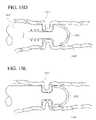
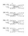
- FIGS. 1B , 1 C, 1 D, 1 E, and 1 Fillustrate embodiments of a balloon catheter.
- FIG. 1Gillustrates a side sectional view of another exemplary embodiment of an introducer consistent with the present invention, wherein the introducer includes a drug delivery element and a strain gauge and is shown deployed in the cervix of a patient;
- FIG. 2illustrates a side sectional view of an exemplary embodiment of a system of the present invention, wherein an introducer includes a radiopaque ring and is shown deployed in the cervix, and a tissue removal device with a side-saddle camera has been advanced through the introducer and into the uterus of a patient;
- FIG. 2Aillustrates a side sectional view of the distal end of a tissue removal device consistent with the present invention, wherein the device includes an oscillating cutter;
- FIG. 2Billustrates a side sectional view of the distal end of another tissue removal device consistent with the present invention, wherein the device includes a rotating cutter;
- FIG. 2Cillustrates a side sectional view of the distal end of a tissue removal device and side-saddle camera, consistent with the present invention
- FIG. 3illustrates a side sectional view of another exemplary embodiment of a system consistent with the present invention, wherein an introducer is shown deployed in the cervix of a patient, and a subsonic treatment device has been advanced through the introducer and into the uterus;
- FIG. 3Aillustrates a side view of the distal end of the subsonic treatment device of FIG. 3 ;
- FIGS. 3B , 3 C, 3 D, and 3 Eillustrate an embodiment of a vibration device to sever tissue, vessels, and mucous.
- FIG. 4illustrates a side view of another exemplary embodiment of an introducer consistent with the present invention, wherein the introducer includes a removable needle assembly and an inflatable balloon near its distal end;
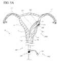
- FIG. 5illustrates a side sectional view of another exemplary embodiment of a system consistent with the present invention, wherein an introducer is shown deployed through the vaginal wall of a patient and a treatment device has been advanced through the introducer to a location outside the uterus and proximate a fibroid in the uteral wall;
- FIG. 5Aillustrates a side sectional view of another exemplary embodiment of a system consistent with the present invention, wherein an introducer is shown deployed through the vaginal wall of a patient, a treatment device including a magnet in its distal portion has been advanced through the introducer to a location outside the uterus and a stabilizing magnetic device has been advanced into the uterus proximate a fibroid;
- FIG. 6illustrates a side sectional view of an exemplary method consistent with the present invention, wherein a first treatment device has been advanced through the cervix and a fallopian tube and is accessing the outside of a fallopian tube, and a second treatment device has been advanced through the cervix and a fallopian tube and is accessing the outside of the uterus proximate a fibroid;
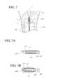
- FIG. 7illustrates a side sectional view of an exemplary drug delivery device consistent with the present invention, wherein the device is deployed in the cervix of the patient and integral needles are deployed into the cervical wall;
- FIG. 7Aillustrates a side sectional view of the drug delivery device of FIG. 7 , wherein the needles are in the retracted position;
- FIG. 7Billustrates a side sectional view of the drug delivery device of FIG. 7 , wherein the needles are in an deployed position
- FIG. 7Cillustrates a side sectional view of another exemplary drug delivery device consistent with the present invention, wherein the device includes a vacuum source and suction ports for attracting tissue toward a drug delivery element;
- FIG. 8illustrates a side sectional view of another exemplary drug delivery device consistent with the present invention, wherein the device is deployed in the cervix of the patient and integral exit holes allow fluid to pass into the cervical wall;
- FIG. 8Aillustrates a side view of the distal end of the drug delivery device of FIG. 8 , wherein the device is deployed over an occluding guidewire;
- FIG. 8Billustrates a side view of the proximal end of the drug delivery device of FIG. 8A .
- FIG. 9illustrates a side sectional view of another exemplary drug delivery device consistent with the present invention, wherein the device is deployed in the cervix of the patient, an integral balloon has been inflated and integral exit holes in the balloon allow fluid to pass into the cervical wall;
- FIG. 9Aillustrates a side view of the distal end of the drug delivery device of FIG. 9 , wherein the device is deployed over a guidewire and the balloon is inflated;
- FIG. 9Billustrates a side view of the proximal end of the drug delivery device of FIG. 9A .
- FIG. 10illustrates a side sectional view of an exemplary scaffolding device consistent with the present invention, wherein the device has been deployed in the uterus of a patient;
- FIG. 10Aillustrates a side sectional view of the scaffolding device of FIG. 10 , wherein a control shaft has been near fully extended and a scaffold is partially deployed;
- FIG. 10Billustrates a perspective view of an exemplary scaffolding device consistent with the present invention, wherein the scaffolding assembly comprises two resiliently biased arms;
- FIG. 10Cillustrates a perspective view of an exemplary scaffolding device consistent with the present invention, wherein the scaffolding assembly includes three resiliently biased arms;
- FIG. 10Dillustrates a side sectional view of the scaffolding device of FIG. 10B , wherein the scaffolding device has been inserted through an introducer of the present invention and has its distal portion in the uterus of a patient;
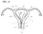
- FIG. 11illustrates a side sectional view of an exemplary visualization apparatus consistent with the present invention, wherein a camera device, a first light source and a second light source have been advanced into the uterus of a patient;
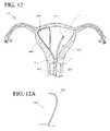
- FIG. 12illustrates a side sectional view of an embodiment of a system consistent with the present invention, wherein a uteral volume occupying device and a treatment device have each been advanced into the uterus of a patient;
- FIG. 12Aillustrates a side view of an example of a wire shaping device consistent with the present invention
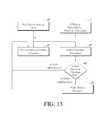
- FIG. 13illustrates a flow chart of an embodiment of a method of dilation, consistent with the present invention.
- FIGS. 14A and 14Billustrate side views of an embodiment of a tubal sterilization device.
- FIGS. 15A , 15 B, 15 C, 15 D, and 15 Eillustrate side views of an embodiment of a tubal sterilization device.
- FIGS. 16A , 16 B, 16 C, 16 D, 16 E, 16 F, 16 G, and 16 Hillustrate side views of an embodiment of a tubal sterilization device.
- FIGS. 17A , 17 B, 17 C, 17 D, 17 E, 17 F, and 17 Gillustrate side views of an embodiment of a tubal sterilization device.
- FIGS. 18A-18Fillustrate an embodiment of a tubal sterilization device for occluding fallopian tubes.
- FIGS. 19A , 19 B, and 20illustrate an embodiment of an implant configured for placement in fallopian tubes to prevent pregnancy.
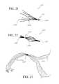
- FIGS. 21 , 22 , and 23illustrate another embodiment of an implant configured for placement in fallopian tubes to prevent pregnancy.
- FIG. 24illustrates an embodiment of an apparatus and method for using a photodynamic drug to prevent abnormal bleeding in the uterus.
- trans-vaginal-wallrefers to devices or procedures which enter the vaginal opening, travel down the vaginal canal, and exit through the vaginal wall proximal to the cervix.
- trans-cervicalrefers to devices or procedures which enter the vaginal opening, travel down the vaginal canal, pass through the cervical canal and enter the uterus.
- trans-uteralrefers to devices or procedures which pass through the wall of the uterus.
- drugrefers to all drugs and other agents that may be included in the systems, methods apparatus and devices of the present invention; either by including the drug into a coating or an integral reservoir of a component; or by provided to the patient through other means such as via a lumen and exit port which is in fluid communication with a supply of the drug such as an infusion pump or syringe.
- Drugsshall include not only pharmaceutical compounds such as anesthetics, anti-thromboties, thrombotics, anti-bacterial drugs and chemotherapeutics, but also other agents such as ionic solutions, hormones, genes, vitamins, clotting agents, naturally occurring substances such as extracts from plants, and any other compound or agent applicable to the procedures contained herein.
- patientrefers to any animal, such as a mammal and preferably a human.
- patientsinclude but are not limited to: individuals requiring medical assistance and healthy individuals.
- Systems, methods, apparatus and devices consistent with the inventionprovide improved diagnostic and therapeutic gynecologic and urologic procedures and outcomes. The simplified, safer use provided allows these procedures to be performed in locations such as a doctor's office or health clinic, eliminating the high costs associated with a hospital setting.
- Specific devices of the present inventionreduce the pain encountered by the patient during and after the associated diagnostic or therapeutic procedure.
- the devices and apparatusprovide to the clinician operator precision in both manipulation and device actions, and often allow reversibility of one or more steps of the procedure without undesirable consequence.
- a hysteroscopic morcellator(or an introducer) is provided which can be placed into the patient to provide a stabile, working platform to support simplified introduction of one or more diagnostic, treatment or other devices.
- the hysteroscopic morcellatorcan comprise an elongate shaft with one or more internal lumens.
- the proximal end of the shaftmay include one or more access ports, such as fluid access ports and device entry ports, as well as one or more controls such as buttons, knobs or levers used to manipulate the hysteroscopic morcellator or activate a mechanical or electronic module of the hysteroscopic morcellator.
- the hysteroscopic morcellatorpreferably accepts devices comprising elongate shafts, sequentially or simultaneously.
- the hysteroscopic morcellator systemalso permits the administration and or removals of fluid from the patient, such as fluid administered to the uterus, while also providing fluid stasis or maintaining stasis to a maximum pressure at which fluid can be automatically evacuated.
- the hysteroscopic morcellator systemalso permits the administration of one or more drugs, such as anesthetic drugs or clotting agents.
- the hysteroscopic morcellator systemmay be introduced through the cervix and into the uterus, through the vaginal wall to a location outside the uterus (trans-vaginal-wall), or through another entry path to a specific anatomical location within the patient.
- the systemspreferably include one or more of the hysteroscopic morcellator, a treatment device, a tissue removal device, a subsonic treatment device, a drug delivery device, a dilating device, a vaginal-wall-crossing device, a distension device, a volume occupying device, a stabilizing device, a visualization apparatus and a navigation apparatus, all of the present invention, and other devices applicable to gynecological procedures.
- the systems of the present inventionare simple to use, and provide reduced risks while enhancing outcomes.
- Treatment Deviceswhich allow a clinician to perform, individually or in combination with additional devices, one or more gynecologic and urologic procedures.
- the treatment devices providedinclude but are not limited to: devices which remove, denature or otherwise treat undesired tissue; devices which modify the structure of a vessel such as a fallopian tube or blood vessel occlusion device; drug delivery devices; and other therapeutic or diagnostic devices.
- the treatment devicespreferably include an elongate shaft, and the shaft may include one or more internal lumens.
- the proximal end of the shaftmay include one or more access ports, such as fluid access ports and device entry ports.
- a handlemay be included on the proximal end, the handle including one or more controls such as buttons, knobs or levers used to manipulate the elongate shaft or activate a mechanical or electronic module of the device.
- the treatment devices of the present inventionmay additionally or alternatively perform a diagnostic function. These treatment devices may provide multiple functions, such as diagnostic or treatment functions including applying a tamponade force to bleeding tissue or distending tissue such as uteral wall tissue.
- Treatment devicesinclude tissue removal devices which can be inserted through the hysteroscopic morcellator of the present invention and be subsequently operated to remove tissue.
- Tissue removal deviceare often arranged with vacuum assemblies which provide a vacuum proximate a tissue removal element and evacuate the tissue to be removed to a site outside of the patient's body.
- Treatment devicesinclude subsonic treatment devices which also can be inserted through the hysteroscopic morcellator of the present invention and subsequently deliver subsonic energy to disrupt or otherwise modify tissue such as a fibroid.
- Treatment devicesinclude drug delivery devices which can be placed into the patient and controllably deliver a drug to a specific area of tissue or space, such as the vaginal wall, cervix, uterus, uteral wall or fallopian tube as well as a specific fibroid, polyp, tumor or other tissue mass.
- These drug delivery devicesmay provide additional functions, such as diagnostic or treatment functions including applying a tamponade force to bleeding tissue or distending tissue such as uteral wall tissue.
- Dilating devicesare provided which can be used to dilate the cervix, a penetration tract in the vaginal wall, or other tissue.
- the dilating devicespreferably include an elongate shaft, and the shaft may include one or more internal lumens.
- the proximal end of the shaftmay include one or more access ports, such as fluid access ports and device entry ports.
- a handlemay be included on the proximal end, the handle including one or more controls such as buttons, knobs or levers used to manipulate the elongate shaft or activate a mechanical or electronic module of the device.
- Specific embodimentsinclude “smart” dilation systems and methods which measure one or more parameters (e.g. device parameters such as strain or pressure or patient parameters such as EKG, EEG, blood pressure or respiration).
- One or more algorithmsare applied to the measured parameters and used to control one or more dilation parameters such as rate, force and magnitude.
- These dilation devicesmay be integrated into another device, such as an hysteroscopic morcellator, a treatment device, or other device of the present invention.
- These dilation devicesmay provide additional or alternative functions, such as diagnostic or treatment functions including applying a tamponade force to bleeding tissue, distending tissue such as uteral wall tissue, or delivering a drug to tissue.
- the dilating devices of the present inventionare typically configured to dilate to a diameter less than 9 mm, preferably between 5 and 8 mm, and more preferably between 2 and 5 mm.
- the dilating devices of the present inventionare typically dilated to a pressure not to exceed 300 psi (e.g. balloon dilation pressure), and preferably less than 150 psi.
- Vaginal-wall-crossing devicesare provided that permit safe introduction of one or more devices, such as the hysteroscopic morcellator of the present invention, from inside the vaginal canal, through the vaginal wall to various anatomical locations including but not limited to: the outer wall of the uterus; the outer wall of the fallopian tubes; the ovaries; intra-abdominal locations; other locations and combinations thereof.
- the crossing devicespreferably include an elongate shaft, and the shaft may include one or more internal lumens.
- the proximal end of the shaftmay include one or more access ports, such as fluid access ports and device entry ports.
- a handlemay be included on the proximal end, the handle including one or more controls such as buttons, knobs or levers used to manipulate the elongate shaft or activate a mechanical or electronic module of the device.
- a guidewireis first placed through the vaginal wall, and one or more devices are placed over-the-wire. These crossing devices may provide additional or alternative functions, such as diagnostic or treatment functions including delivering a drug to tissue.
- Distension devicesare provided which can be introduced into a space, such as the uterus, and apply a force to tissue.
- the distension devicesinclude without limitation, for example, scaffolding devices or the like.
- the distension devicesare preferably inserted through the hysteroscopic morcellator of the present invention.
- the distension devicespreferably include an elongate shaft, and the shaft may include one or more internal lumens.
- the proximal end of the shaftmay include one or more access ports, such as fluid access ports and device entry ports.
- a handlemay be included on the proximal end, the handle including one or more controls such as buttons, knobs or levers used to manipulate the elongate shaft or activate a mechanical or electronic module of the device.
- These distension devicesmay provide additional or alternative functions, such as diagnostic or treatment functions including applying a tamponade force to bleeding tissue or delivering a drug to tissue.
- These distension devicesare preferably inserted into the uterus of a patient such that the distension assembly preferably distends the uteral cavity to a volume equivalent to that which would be attained via a liquid distention media at a pressure of at least 40 mm of HG but not greater than 100 mm HG and preferably approximating 70 mm Hg.
- Volume Occupying devicesare provided which can be introduced into a space, such as the uterus, and occupy space within the uterus.
- the volume occupying devicesare preferably inserted through the hysteroscopic morcellator of the present invention.
- the volume occupying devicespreferably include an elongate shaft, and the shaft may include one or more internal lumens.
- the proximal end of the shaftmay include one or more access ports, such as fluid access ports and device entry ports.
- a handlemay be included on the proximal end, the handle including one or more controls such as buttons, knobs or levers used to manipulate the elongate shaft or activate a mechanical or electronic module of the device.
- volume occupying devicesprovide the function of taking up space in a cavity, such as taking up space in the uterus to reduce the amount of fluid delivered to the uterus in a diagnostic or therapeutic procedure.
- These volume occupying devicesmay provide additional or alternative functions, such as diagnostic or treatment functions including applying a tamponade force to bleeding tissue, distending tissue such as uteral wall tissue, or delivering a drug to tissue.
- Stabilizing devicesare provided which are used to stabilize one or more separate devices, such as a treatment device of the present invention.
- Stabilizing devicesmay include magnets which attract a corresponding magnet integral to the separate device such as to position a treatment device proximate to tissue to be treated.
- the stabilizing devicespreferably include an elongate shaft, and the shaft may include one or more internal lumens.
- the proximal end of the shaftmay include one or more access ports, such as fluid access ports and device entry ports.
- a handlemay be included on the proximal end, the handle including one or more controls such as buttons, knobs or levers used to manipulate the elongate shaft or activate a mechanical or electronic module of the device such as an electromagnet located in the distal portion of the shaft.
- These stabilizing devicesmay provide additional or alternative functions, such as diagnostic or treatment functions including applying a tamponade force to bleeding tissue, distending tissue such as uteral wall tissue, or delivering a drug to tissue.
- Visualization apparatusare provided which provide enhanced imaging of target anatomical locations within the patient.
- the apparatusinclude one or more of: miniaturized cameras; infrared cameras; deployable light sources; stabilizing mechanisms; image stabilizing modules and processing; and improved and cost-reduced displays (e.g. a laptop screen display).
- the visualization apparatuspreferably include one or more devices comprising an elongate shaft, and the shaft may include one or more internal lumens.
- the proximal end of the shaftmay include one or more access ports, such as fluid access ports and device entry ports.
- a handlemay be included on the proximal end, the handle including one or more controls such as buttons, knobs or levers used to manipulate the elongate shaft or activate a mechanical or electronic module of the device.
- These visualization apparatusmay provide additional or alternative functions, such as diagnostic or treatment functions including applying a tamponade force to bleeding tissue, distending tissue such as uteral wall tissue, or delivering a drug to tissue.
- Navigating apparatusare provided which enable a clinician to navigate one or more diagnostic or therapeutic devices to perform a gynecologic procedure.
- the navigation apparatuspreferably include one or more of: an electromagnetic (EM) beacon and/or receiver; a light emitter and/or detector; and a magnetic source and/or a detector.
- the navigation apparatuspreferably include one or more devices comprising an elongate shaft, and the shaft may include one or more internal lumens.
- the proximal end of the shaftmay include one or more access ports, such as fluid access ports and device entry ports.
- a handlemay be included on the proximal end, the handle including one or more controls such as buttons, knobs or levers used to manipulate the elongate shaft or activate a mechanical or electronic module of the device.
- These navigation apparatusmay provide additional or alternative functions, such as diagnostic or treatment functions including applying a tamponade force to bleeding tissue, distending tissue such as uteral wall tissue, or delivering a drug to tissue.
- Shape-modifying wiresare provided which are slidingly received by one or more lumens of a device of the present invention, such as a morcellating or other treatment device used to access and treat a fibroid. Shapes on the one or more shaping wires can bias the elongate shaft of the device, such as at a distal portion, to a pre-determined shape. In a preferred embodiment, multiple shaping wires with varied shapes are provided to accommodate different procedures and/or access to different anatomical locations.
- Numerous devices of the present inventioninclude an elongate shaft, similar in construction to shafts used in laparoscopic and percutaneous devices.
- the shaftsmay be manufactured in a “lay up” process including multiple layers of similar or dissimilar materials, such as layers of flexible biocompatible material separated by a braided material such as metal wire or plastic filament.
- the constructionis chosen to provide adequate column strength and torqueability to access the desired anatomical locations and perform the desired actions.
- Each shaftpreferably has a blunt or otherwise atraumatic distal tip.
- the shaftsmay include one or more lumens, such as a lumen configured to slidingly receive an elongate device such as a treatment catheter or guidewire, a lumen configured to allow fluid delivery and/or fluid sampling or removal; an inflation lumen configured to allow inflation of a balloon; a mechanical linkage lumen configured to slidingly receive a cable such as to transmit force through the shaft (e.g. from a lever on a handle on the proximal end of the shaft); a lumen configured to slidingly receive a shaping wire of the present invention; other lumens and combinations thereof.
- Each lumenmay include one or more mechanical keys, such as to orient an inserted device such as to orient a tissue treatment element or camera device toward a window.
- each lumenmay be a blind lumen which has an entry port near the proximal end of the shaft, but terminates within the shaft without exiting the distal tip or an exit hole along the shaft.
- a blind lumenmay be incorporated which includes a “window” through which a camera element may be positioned to view outside the elongate shaft.
- each lumenmay include a mechanical stop, such as to limit the travel of an inserted device.
- the elongate shafts of the present inventionmay include a reinforced section such as a section located at the portion of the shaft that, when inserted into the body, is in proximity to the cervix.
- the reinforced sectioncan provide the function of preventing collapse of an internal lumen of the shaft (enhanced radial strength) as well as prevent undesired perforation out of the shaft and into tissue such as cervical tissue.
- the reinforced sectionmay comprise the braiding process described hereabove, and may be provided along a majority of length of the shaft, or a small portion.
- the shaftmay include variable stiffness along its length, and may allow the stiffness to be adjusted, such as through the insertion of a stiffening wire, or by pressurizing an internal (blind) lumen of the shaft.
- the shaftmay include along its length one or more clinician inflatable balloons, such as compliant or non-compliant nylon or PET balloons configured to dilate, deflect the device or neighboring tissue; deliver a drug; or perform another function.
- the elongate shafts of the present inventionare typically less than 9 mm in diameter, and preferably between 5 to 8 mm in diameter, and more preferably between 2 and 5 mm in diameter.
- the elongate shafts of the present inventionmay include clinician controlled deflection means, preferably one or more pull wires attached at their proximal end to a control in a handle on the proximal end of the shaft, and attached on their distal end to a portion of the shaft, such as a distal portion of the shaft. Advancement and retraction of the pull wire causes a portion of the shaft to deflect, such as to bring a treatment element of the present invention in proximity to tissue to be treated.
- the shaftsmay further include one or more internal conduits, such as wires or optical fibers which do not need to be advanced or retracted. These conduits may be embedded in the wall of the shaft, fixed to an internal lumen, or sandwiched between to layers present in a layered construction.
- Wirescan be used to transmit electrical signals or energy, in either direction in the shaft.
- Fiber optic cablescan be used to transmit light energy (e.g. laser energy) or signals (e.g. images from a lens), in either direction in the shaft.
- the shafts of the present inventioninclude a handle on their proximal end, and the handle includes on or more controls to activate one or more portions of the device.
- a “kill-switch” controlis included to allow the clinician to quickly stop an ongoing action.
- the shafts and other components of the devices of the present inventionare constructed of biocompatible materials.
- the devicesmay be configured for one-time use or be resterilizable.
- the materialsinclude medical grade metals, plastics and other materials.
- Shaped memory metalssuch as Nitinol and shaped memory polymers may be used to provide controllable material properties or meet specific elasticity and/or resiliency requirements.
- the shafts and other componentsmay include one or more coatings, such as coatings selected from the group consisting of: anti-infective drugs, anti-thrombogenic drugs; clotting agents; chemotherapeutics; anesthetics such as lidocaine; other drugs; and combinations thereof.
- the shafts and other componentsmay include drug delivery means, such as drug reservoirs (e.g.
- markersmay be integral to a component of the device, such as a marker selected from the group consisting of: visible and non-visible markers; radiopaque markers; magnetic markers; ultrasonically reflective markers; and combinations thereof.
- a functional elementmay be mounted to the shafts or other components of the devices of the present invention. These functional elements may include a sensor or transducer and/or another functional element such as a camera or marker as described hereabove.
- Applicable sensorsinclude but are not limited to: electrodes such as electrical mapping electrodes; temperature sensors; pressure sensors; strain gauges; accelerometers; force sensing resistors; position sensors such as linear or rotary encoders; magnetic sensors such as hall effect transistors; optical sensors such as phototransistors; physiologic sensors such as EKG; EEG; respiration; blood sensors such as a blood gas sensors such as an O2 saturation sensors; glucose sensors; blood pressure sensors; pH sensors; other physiologic sensors; and combinations thereof.
- Applicable transducersinclude but are not limited to: magnets; electrodes such as radiofrequency electrodes; heat generators; cryogenic generators; force or space-occupying generators such as an expandable balloon or solenoid; drug delivery elements such as iontophoretic elements; sound transducers such as acoustic transducers, ultrasound transducers and subsonic transducers; radiation sources; light sources such as visible or infrared light sources configured to provide a beacon for navigation and ultraviolet light sources configured to treat infection or kill bacteria; visualization elements such as cameras, lenses, fiber optics and ultrasound crystals; other functional elements; and combinations thereof. Functional elements may further include elements to cause dissection of tissue, such as blunt dissection projections and fluid jets.
- the systems, methods, apparatus and devices of the present inventionare applicable to patients with one or more of the following conditions:
- the systems, methods, apparatus and devices of the present inventionare applicable to performing one or more therapeutic or diagnostic gynecologic and urologic procedures. These procedures may be performed inside or outside the uterus. Applicable primary procedures include but are not limited to:
- the systems, methods, apparatus and devices of the present inventionmay be used to perform one or more additional procedures, including but not limited to:
- the systems, methods, apparatus and devices of the present inventionmay provide and/or utilize various means and routes of access to an internal location within the patient. Routes of access include but are not limited to:
- the devices and apparatus of the present inventionmay comprise an elongate shaft that includes one or more lumens such as to slidingly receive one or more separate devices also comprising an elongate shaft.
- the device lumensmay be configured to support over-the-wire insertion over a standard guidewire, or alternatively a side-car mounted near the distal end of the shaft may be provided to support monorail (also known as rapid exchange) insertion.
- the device lumens, such as the hysteroscopic morcellator of the present inventionmay be sized and be otherwise configured to slidingly receive one or more devices including but not limited to:
- the device lumensmay be sized and include access elements such as luer fittings to attach to drug delivery devices such as syringes and infusion pumps.
- the device elongate shaftmay be sized and otherwise configured to be passed through one or more devices including but not limited to:
- hysteroscopic morcellator 100 aincludes an elongate, hollow shaft, sheath 110 , which is configured to have distal end 111 (preferably with an atraumatic leading edge) be inserted into the body of a patient, such as through the cervix and into the uterus, to provide a working channel to introduce tools through a lumen of sheath 110 and into the uterus.
- distal end 111preferably with an atraumatic leading edge
- distal end 111 of sheath 110is placed into the vaginal opening of a patient, and manipulated to penetrate through the vaginal wall (such as by advancing over a pre-existing guidewire penetrating the vaginal wall), such as to provide a working channel to introduce tools through a lumen of sheath 110 to a location outside the uterus.
- Sheath 110may be configured to slidingly receive two or more devices, independently or simultaneously.
- sheath 110includes multiple lumens along its length, each lumen configured to slidingly receive a separate device. Sheath 110 may remain in place throughout the subsequent procedure, or for a portion of the procedural steps. Sheath 110 may be repositioned during the procedure, such as to advance or withdraw sheath 110 .
- Sheath 110is manufactured from medical-grade plastics, metals and other biocompatible material such as a sheath including a Teflon outer layer.
- One or more portions of sheath 110may be radiopaque, such as by inclusion of a barium sulfate in plastic material or inclusion of one or more metal portions which provide sufficient radiopacity.
- distal end 111includes a radiopaque marker.
- Sheath 110is preferably of a braided construction as has been described hereabove, and includes a reinforced portion, reinforcement 115 (e.g.
- reinforcement 115may be configured to prevent a device inserted into sheath 110 from inadvertently puncturing out the side of sheath 110 , such as to prevent a puncture that would damage cervical or other patient tissue unexpectedly.
- device insertion port 120On the proximal end of sheath 110 is device insertion port 120 , which provides access to an internal lumen of sheath 110 and has been configured to maintain fluid stasis with or without a device inserted through it.
- Port 120preferably has an “X” cut opening through one or more diaphragms that maintain that fluid seal.
- the thicknesses of the diaphragms and the materials chosenpreferably maintain pressure up to a predetermined level (e.g. 50 mm Hg) after which fluid is automatically evacuated to prevent damage to the patient's internal tissue.
- Input valve 121 and output valve 122are input valve 121 and output valve 122 , each of which includes a standard luer connector for attachment to standard fluid infusion lines.
- Input valve 121 and output valve 122may include simple one-way valves or more sophisticated valves that open (in either direction or both) at pre-determined pressures.
- fluid infusion and fluid evacuation means(not shown but preferably gravity driven or pump driven fluid movement means), can be attached to port 121 and port 122 and control the level of fluid introduced into the patient via hysteroscopic morcellator 100 a .
- sheath 110is a single lumen and the fluid is introduced through that lumen.
- sheath 110includes multiple lumens and fluid can be delivered or evacuated through one or more lumens, simultaneously or independently.
- a volume of liquid and level of liquid pressureare used to visualize the internal space and/or provide space to manipulate one or more devices.
- a gel or gasis delivered into the patient.
- Hysteroscopic morcellator 100 amay include a handle, not shown, on its proximal end.
- the handlemay include one or more controls, as has been described hereabove.
- Sheath 110may include one or more valves within one or more lumens of sheath 110 , such as a valve near the distal end 111 .
- hysteroscopic morcellator 100 amay include a balloon along sheath 110 , such as a balloon configured to dilate tissue such as the cervix or the vaginal wall. In an alternative embodiment, multiple balloons are employed, such as a balloon on a balloon configuration.
- Each balloon integrated into sheath 110may have an integrally mounted functional element, as has been described hereabove but preferably a pressure or force sensor used to provide information to the clinician or a system component regarding dilation conditions (reference FIG. 13 herebelow).
- Sheath 110may include one or more functional elements along its length, such as a vibrational transducer configured to assist in dilation.
- Sheath 110may include a lumen for insertion of a shaped wire, such as a wire configured to resiliently bias sheath 110 and/or a wire configured to place a “straightening” bias on the cervical canal during hysteroscopic morcellator insertion, once inserted or both.
- sheath 110includes an expandable cage structure, not shown but protruding from distal end 111 .
- the expandable cage structuremay have a fluted geometry such as a geometry configured to follow the contour of the uterus when hysteroscopic morcellator 100 a is inserted through the cervix.
- Hysteroscopic morcellator 100 of FIG. 1 and the numerous embodiments of the hysteroscopic morcellators described throughout this application,are sized to accommodate the one or more devices placed through sheath 110 , while remaining as small as possible to reduce tissue trauma and pain to the patient, especially when sheath 110 is placed through the cervix of a patient.
- sheath 110 of hysteroscopic morcellator 100is typically less than 9 mm in diameter and preferably less than 8 mm diameter. In another embodiment, sheath 110 is less than 7 mm in diameter. In another embodiment, sheath 110 is less than 6 mm in diameter. In another embodiment, sheath 110 is less than 5 mm in diameter. In another embodiment, sheath 110 is less than 4 mm in diameter. In another embodiment, sheath 110 is less than 3 mm in diameter. In another embodiment, sheath 110 is less than 2 mm in diameter. Sheath 110 is configured in size and rigidity to prevent painful and potentially destructive dilation of the cervix.
- Hysteroscopic morcellator 100 bhas a dual balloon construction and includes sheath 110 , of similar construction to sheath 110 of FIG. 1 .
- Hysteroscopic morcellator 100 bis shown over a guidewire 131 , such as an 0.038′′ standard interventional guidewire, which has been advanced through vagina V, through cervix C and into uterus U.
- An inflatable balloon introducer assembly 150includes balloon 151 and shaft 150 and is shown having been advanced into the cervix C of a patient and balloon 151 inflated (inflation lumen and inflation port not shown).
- Inflation of balloon 151is used to pre-dilate cervix C such that sheath 110 can be advanced into cervix C.
- Inflation balloon 151is preferably less than 9 mm in diameter when fully inflated, and more preferably between 2 and 8 mm in diameter.
- Shaft 155which is slidingly received by sheath 110 , may be pulled back prior to advancement of sheath 110 , or balloon 151 may be left in place, although preferably partially deflated prior to advancement.
- balloon assembly 150 including shaft 155 and balloon 151may be configured to be completely removed from sheath 110 such as after sheath 110 is placed to its desired location in the patient's body.
- further dilation of the cervixmay be accomplished by subsequent inflation of balloon 151 , and/or via inflation of a balloon integral to sheath 110 , balloon 116 (inflation lumen and inflation port also not shown). Inflation of either balloon 151 or balloon 116 , or both, may be used to anchor sheath 110 in place.
- device insertion port 120On the proximal end of sheath 110 is device insertion port 120 , which provides access to an internal lumen of sheath 110 and is in fluid communication with fluid transfer port 123 configured to introduce and/or remove fluid or other media through sheath 110 and into the patient as has been described hereabove.
- Port 120includes a rotating collar 124 , which can be rotated to permit devices to pass through port 120 as well as seal around those devices, such as via a diaphragm which seals around inserted devices similar to a Tuohy Borst valve configuration. Port 120 further provides fluid stasis when no device is inserted through it.
- Guidewire 131may be replaced with a different guidewire, such as with a guidewire with different stiffness or lubricious properties. Guidewire 131 may remain in place for a majority of the procedure, or may be removed early on.
- a balloon catheterapproximately 40 cm in overall length and having an uninflated cross-section diameter of less than 4 mm but preferably less than 3 mm having two or more lumens, one extending to the distal tip for a fiber optic or guidewire and one extending to and exiting within the balloon itself for inflation and deflation. Both lumens exit at the proximal end of the catheter.
- the “through-lumen” used for passing the guidewire or fiber opticcan be open ended or have a capped end to keep the fiber optic from touching body fluids.
- the balloon having a length preferably 12 cmis available in several inflated diameters to dilate the cervix to the appropriate size for the desired instrument.
- the preferred balloon inflation diameters measured at the midpoint of the balloonare 10 mm, 9 mm, 8 mm, 7 mm, 6 mm, 5 mm and 4 mm.
- the desired inflation pressuremay be greater than 25 atm and in some embodiments greater than 40 atm.
- the balloonhaving been made of a non-compliant material such as polyethylene teraphthalate (PET) is configured with specific attributes that enable the balloon to inflate distally and proximally similar to a dumbbell or dog bone shape as it grows to its fully distended sausage shape.
- PETpolyethylene teraphthalate
- the purpose of the evolving shape from a dumbbell or dogbone shape to a fully distended shapeallows the balloon to remain anchored in its intended location throughout the inflation process. If the balloon preferentially inflated proximally first or distally first the balloon would squirt out from the structure it is trying to dilate.
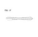
- FIG. 1Bshows the uninflated balloon across the cervix.
- the balloon 1002is affixed to a catheter equipped with an inflation lumen which is connected to a source of inflation media such as a syringe 1004 .
- FIG. 1Cshows the balloon 1002 as it is being inflated. The anterior and posterior portions of the balloon are distending first allowing the balloon to remain in position across the cervix.
- FIG. 1Dshows the balloons fully distended and the cervix fully dilated to the same size as the balloon.
- FIG. 1Eshows multiple inflation lumens opening into the balloon.
- the balloon 1002comprises a proximal zone 1006 , a distal zone 1008 and a central zone 1010 .
- the central zone 1010When positioned initially for the procedure, the central zone 1010 will be held in compression by the cervix.
- a proximal inflation port 1012is provided for placing the proximal zone 1006 in fluid communication with the inflation media source 1004 by way of an elongated inflation lumen extending through the catheter body 1016 .
- a distal inflation port 1014places the distal zone 1008 in fluid communication with the source of inflation media 1004 by way of either the first inflation lumen or a second inflation lumen extending throughout the catheter body 1016 .
- Expression of inflation media from the source 1004will therefore inflate the proximal zone 1006 and the distal zone 1008 under approximately the same inflation pressure, which, in combination with the radially constricted force applied by the cervix in the central zone 1010 , will cause the balloon to expand in an initial dog bone configuration.
- the balloon 1002may be configured with an internal baffle (not illustrated) to isolate the proximal section 1006 from the distal section 1008 .
- each of the proximal section 1006 , distal section 1008 and intermediate section 1010may comprise distinct inflatable balloons.
- the proximal balloon 1006 and distal balloon 1008will be coupled to a common inflation lumen enabling simultaneous inflation.
- the central balloon 1010is placed in communication with a source of inflation media by way of a unique inflation lumen. In this manner, the inflation of the proximal and distal balloons may be controlled separately from the inflation of the central balloon.
- One or more additional lumenmay be provided in the catheter 1016 , depending upon the desired functionality.
- an elongate central lumenmay be provided, extending all the way to the distal tip of the balloon 1002 and further provided with a distal opening.
- This central lumenmay be utilized for any of a variety of purposes, such as for advancing the catheter over a guidewire, and/or for the introduction of fluids and/or tools through the balloon catheter and into the uterus.
- FIG. 1Fshows a lower profile of the catheter under where the balloon is mounted to allows the inflation media to travel along the shaft of the balloon to the areas proximal and distal to the structure. These areas are areas of least resistance and will inflate to a maximum pressure beyond which the balloon will not grow. Once this critical pressure is achieved at the unconstrained ends of the balloon, the dilating force will be directed to the anatomical stricture.
- the balloonis dilated completely, it is left in place for several minutes to stretch the muscles that surround the cervix. Once sufficient stretching is accomplished, the balloon is deflated by drawing back on the plunger of the syringe to remove the inflation media from the balloon.
- the balloon catheterhas a third lumen to allow the user to distend the uterus with fluid while the balloon catheter is in place.
- the balloon catheterthereby provides a stopper function on the uterus to prevent the uterine distension fluid from leaking out.
- the third lumencan be used for both inflow and outflow of fluid from the uterus.
- the ballooncan be made of a compliant material such as silicone or latex.
- the ballooncan be used both within the cervix as well as within the uterus to act as a tamponade against uncontrolled bleeding.
- a compliant balloon materialallows the balloon to take on the shape of the organ in which it is placed and provides uniform pressure when compared to a non-compliant balloon.
- This balloonmay also have hydrophilic coatings that can carry drugs such as hemostatic agents to aid in the cessation of blood flow or chemotherapeutic agents to treat cancer or ablative agents to sclerose the lining of the uterus.
- Hysteroscopic morcellator 100 cincludes sheath 110 with distal end 111 , device insertion port 120 with rotating collar 124 and fluid transfer port 123 , all of similar construction to similar components of hysteroscopic morcellator 100 a of FIG. 1 and hysteroscopic morcellator 100 b of FIG. 2 .
- Hysteroscopic morcellator 100 chas been placed over guidewire 141 and advanced such that its distal portion resides within cervix C and its distal end is within uterus U of a patient.
- Hysteroscopic morcellator 100 cincludes a force measuring element, strain gauge 113 , which is used to monitor forces exerted on sheath 110 (and the corresponding resultant forces exerted on the neighboring tissue). Wires, not shown but attached to strain gauge 113 and traveling proximally through sheath 110 , attach to an electronic module, also not shown, and provide pressure or other force information to the clinician or a system component which processes the information.
- Hysteroscopic morcellator 100 cfurther includes drug delivery element 114 , such as a drug delivery mechanism.
- Drug delivery element 114may be a simple drug coating, or may be a depot that stores a drug such as an anesthetic and delivers the drug via osmosis, iontophoresis or other drug delivery mechanism.
- drug delivery element 114is a pressure releasable sack, such as a sack with a duck bill valve, and when sufficient pressure is applied to the sac, such as via the cervix, a drug, such as lidocaine, is delivered.
- drug delivery element 114includes multiple pressure-driven sacks, such as multiple sacks in different locations and/or multiple sacks with different delivery pressure properties.
- Hysteroscopic morcellator 100 cfurther includes a visualization apparatus, visualization element 112 preferably a forward looking visualization tool such as forward looking ultrasound, or a lens that provides an image to a camera, not shown, but preferably a camera system that receives an image from a fiber optic in optical communication with the lens.
- visualization element 112preferably a forward looking visualization tool such as forward looking ultrasound, or a lens that provides an image to a camera, not shown, but preferably a camera system that receives an image from a fiber optic in optical communication with the lens.
- a displaynot shown but preferably integrated into a laptop computer via a USB or video connection, provides the camera image to the clinician and/or patient.
- System 10includes hysteroscopic morcellator 100 d and tissue removal device 200 which includes an integral visualization apparatus, camera 256 mounted to side-saddle catheter 250 .
- Hysteroscopic morcellator 100 dincludes sheath 110 , device insertion port 120 and fluid transfer port 123 , all of similar construction to similar components of hysteroscopic morcellators 100 a , 100 b and 100 c hereabove.
- Hysteroscopic morcellator 100 dhas been placed and advanced such that its distal portion resides within cervix C and its distal end provides access within uterus U of a patient.
- Sheath 110includes a marker, radiopaque ring 117 which can be used by the clinician to determine and/or confirm with fluoroscopy the diameter (e.g. the inside diameter) of sheath 110 at the location of ring 117 , such as to confirm or rule out the condition where the cervix may be undesirably compressing sheath 110 .
- ring 117is an ultrasonically reflective marker enabling the condition to determine the associated diameter by using ultrasound, such as via an ultrasound device commonly located in a gynecologist office.
- Tissue removal device 200a morcellating device, has been advanced through port 120 , through a lumen of sheath 110 , and into the uterus U of a patient.
- Tissue removal device 200includes an elongate shaft, tube 201 , which includes on its distal end 203 a cutout, window 202 .
- a cutting element 210is present within window 202 such that as the distal end of tube 201 is manipulated near tissue, cutting element 210 will cut that tissue.
- Vacuum meansnot shown put in fluid communication with a lumen of tube 201 and window 202 , evacuate the pulverized, cut or otherwise detached particles to a location outside of the patient. In a preferred embodiment, vacuum and evacuation means are integral to a handle of device 200 .
- vacuum and evacuation meansare connected to a port which is integral to a handle of device 200 .
- Cutting element 210of one or more configurations such as the configurations described below in reference to FIGS. 2A and 2B , is preferably attached to a speed control mechanism, not shown.
- the speed control mechanismis simplified for use by including one or more feedback means (e.g. electromotive feedback, rotation or other speed feedback, vibrational feedback, physiologic feedback such as EKG or blood pressure, or other feedback), wherein the feedback means can be used to automatically control the speed, greatly simplifying use for the clinician.
- the clinician available feedbackis limited to a small number of finite settings, such as less than 10 settings.
- a kill-switchis included on a handle of the device, which is readily accessible to the clinician and upon activation removes power and/or applies a breaking function to instantaneously stop the cutting motion.
- a side-saddle catheter 250which includes sleeve 252 (e.g. a Teflon sleeve) which slidingly surrounds tube 201 .
- sleeve 252e.g. a Teflon sleeve
- Advancement and retraction of an elongate shaft, shaft 205causes a visualization apparatus, camera 255 to be correspondingly advanced and retracted relative to tube 201 .
- the image received from camera 255is used by the clinician to position the window 202 of tissue removal device 200 near one or more fibroids, such as fibroid F 1 located within the wall of uterus U and fibroid F 2 attached to the wall of uterus U.
- Camera 225may utilize CCD and/or MEMS mirror control technology to produce and/or transfer an image.
- camera 225includes one or more motion sensing elements, such as miniaturized accelerometers or gyros which can be fed back to an image processing system, not shown but preferably external to the patient, such that the image provided to the clinician does not move as the camera is moved.
- side saddle catheter 250includes one or more functional elements, not shown but preferably selected from the list of functional elements provided hereabove.
- the functional elementmay be a fluid delivery port, such as a port configured to deliver saline or other clear fluid to clear the pathway of the camera view or to clean off a contaminated lens.
- FIG. 2Aa preferred embodiment of the cutting element 210 of FIG. 2 is shown.
- the distal end of tube 201 and window 202is shown with an oscillating cutter 211 attached to an elongate control linkage, shaft 221 , which is attached at its proximal end to a reciprocating motor assembly, not shown, but preferably a simplified, precision speed controlled assembly as has been described hereabove.
- the speed assemblyutilizes feedback, also as has been described hereabove.
- FIG. 2Banother preferred embodiment of the cutting element of FIG. 2 is shown.
- tube 201 and window 202is shown with an spinning or rotational cutter 212 attached to an elongate control linkage, shaft 221 , which is attached at its proximal end to a rotational motor assembly, not shown, but preferably a simplified, precision speed controlled assembly as has been described hereabove.
- the speed assemblyutilizes feedback, also as has been described hereabove.
- System 10 of FIG. 2is configured such that the outer diameter of sheath 110 of hysteroscopic morcellator 100 d is minimized. Inserted devices such as tissue removal device 200 (including camera 256 ) and other inserted devices are also minimized in the cross sectional profiles of their distal portions, such that the inner diameter (and thus the outer diameter) of sheath 110 can be reduced.
- sheath 110 of hysteroscopic morcellator 100is typically less than 9 mm in diameter and preferably less than 8 mm diameter.
- sheath 110is less than 7 mm in diameter.
- sheath 110is less than 6 mm in diameter.
- sheath 110is less than 5 mm in diameter.
- sheath 110is less than 4 mm in diameter. In another embodiment, sheath 110 is less than 3 mm in diameter. In another embodiment, sheath 110 is less than 2 mm in diameter. Sheath 110 is configured in size and rigidity to prevent painful and potentially destructive dilation of the cervix.
- System 10includes hysteroscopic morcellator 100 and subsonic treatment device 300 .
- Hysteroscopic morcellator 100includes sheath 110 , device insertion port 120 and fluid transfer port 123 , all of similar construction to similar components of hysteroscopic morcellators 100 a , 100 b , 100 c and 100 d hereabove.
- Hysteroscopic morcellator 100 dhas been placed and advanced such that its distal portion resides within cervix C and its distal end provides access within uterus U of a patient.
- a treatment catheter of the present invention, acoustic generator device 300has been inserted through port 120 , down a lumen of sheath 110 and into the uterus of the patient.
- acoustic generator device 300includes acoustic transducer 310 which comprises housing 302 , preferably a metal can with a lumen 304 , and a sound crystal 303 , configured to deliver subsonic sound waves.
- System 10preferably includes specialized fluid medium, which is injected into uterus U via port 123 and sheath 110 .
- the fluid mediumis configured to adequately conduct the emitted sound waves and provide an impedance mismatch between it and the targeted tissue (e.g. endometrium), such that large amounts of energy (sufficient to destroy or otherwise denature the tissue cells) is transferred to the tissue when the subsonic waves arrive at the interface.
- FIG. 3B and FIG. 3Cshows a cutting mechanism used to expose the fibroid by dissecting or cutting open the myometrium 336 over the fibroid.
- the distension media(saline) would be drained from the uterine cavity allowing the fibroid to become avulsed from the wall of the uterus ( FIG. 3B ). Once avulsed, the uterus would once again be distended with gas or fluid.
- the anchoring end 338 of a vibrational wire or catheter 340would be passed through the vagina and cervix 342 until it engaged the fibroid 330 .
- the catheter or wirewould be attached to the fibroid using struts, a corkscrew or similar type tip.
- the vibrational catheter 340 or wirewould be vibrated at a frequency that places the fibroid 330 in opposite (or dissimilar) motion to the surrounding tissue similar to a sine wave.
- the specific frequency of the vibrational devicecould be set manually or through a feedback mechanism which measures the energy needed to keep the target tissue in a motion offset from the surrounding tissue.
- the vibrational frequencycould be high or low and could be adjusted using the distension pressure within the uterus. Referring to FIG. 3D , the resulting motion from such vibration would cause the tissue, vessels or mucous to sever, releasing the fibroid 330 from the surrounding tissues causing it to ultimately become freed of the uterine wall.
- the fibroid 330can be removed similar to other tissue freed or excised during laparoscopic surgery. Referring to FIG. 3E , in one embodiment, this is done via a morcellating device 342 comprising a powered helical wire or blade 344 that rotates within an aspiration lumen 346 extending throughout an outer tubular body 348 .
- the vibrational catheter 340 or wireis used coaxially within another catheter (not illustrated).
- the inner deviceis coupled to the fibroid as stated above but the outer catheter has extendable tines, feet or a cone shaped tip that can couple with the uterine wall such that the outer catheter maintains stability while the inner vibrational member oscillates at a frequency in opposition to that of the outer stabilizing catheter.
- the shear stress caused by the opposing motion of the two deviceswill cause the fibroid to detach from the uterus along the outer capsule of the fibroid.
- Hysteroscopic morcellator 100 eis configured to puncture through tissue, such as the vaginal wall to perform a trans-vaginal-wall procedure.
- Hysteroscopic morcellator 100 eincludes sheath 110 with balloon 116 and distal end 111 , device insertion port 120 and fluid transfer port 123 , all of similar construction to similar components of hysteroscopic morcellator 100 a , 100 b , 100 c and 100 d hereabove.
- Balloon 116which can be configured to perform one or more functions such as to dilate tissue, to anchor sheath 110 in place and to maintain one or more lumens of sheath 110 in an open state under high loading conditions. Balloon 116 is in fluid communication with inflation lumen 152 and injection port 153 such that a syringe or endoflator attached to the luer of port 153 can be used to inflate balloon 116 .
- Balloon 116includes a miniaturized, integral pressure sensor 154 , which is preferably attached to one or more wires, not shown but traveling proximally and attaching to an electronic module which processes the received signal and provides pressure information to the clinician and/or utilizes the information in one or more ways such as to reduce patient pain such as via the “smart” dilation system and method described in detail in reference to FIG. 13 herebelow. Additional balloons and/or pressure sensors may be integrated into sheath 110 .
- Pull wire 171is fixedly attached at its distal end to a distal portion of sheath 110 , and it is operably attached at its proximal end to knob 172 , such that rotation of knob 172 causes sheath 170 to deflect. As shown in FIG. 4 , rotation of knob 172 that causes pull wire 172 to retract causes the distal end of sheath 110 to deflect to the left and rotation of knob 172 that causes pull wire 172 to advance causes sheath 110 to deflect to the right. In an alternative embodiment, additional one or more pull wires are included to allow a clinician to deflect sheath 110 in multiple directions at multiple points along the length of sheath 110 . Deflection of sheath 110 allows for directional orientation, positioning and advancement of the one or more treatment or other devices that can be inserted into sheath 10 via port 120 (inserted devices not shown).
- Hysteroscopic morcellator 100 eincludes a tissue penetrating assembly comprising needle 161 , an elongate hollow needle preferably constructed of stainless steel or Nitinol, which has fixedly attached on its proximal end, knob 162 .
- Needle 161resides within a lumen of sheath 110 , and is in place when hysteroscopic morcellator 100 e is advanced through tissue.
- Needle 161has an internal lumen sized to slidingly receive guidewire 131 .
- Guidewire 131can be placed trough needle 161 after needle 161 has been advanced through tissue (guidewire loaded from proximal end of needle 161 ).
- guidewire 131can be placed to a target location, such as through the vaginal wall of a patient via another needle device, and then passed through needle 161 (guidewire loaded from distal end of needle 161 ).
- needle 161can be used to deliver anesthetic to tissue prior to needle 161 and/or sheath 110 advancement.
- Hysteroscopic morcellator 100 emay have one or more functional elements, such as a functional element described hereabove and integrated into sheath 110 .
- a functional elementcomprising a visualization apparatus or a portion of a visualization apparatus, such as a camera lens and fiber optic or an ultrasound crystal and associated wiring are contained within sheath 110 .
- Advancement of sheath 110 esuch as through the vaginal wall to a location neighboring the outside of a patient's uterus, may require dissection of tissue.
- hysteroscopic morcellator 100 eincludes a functional element such as a blunt dissector, a fluid jet, or other dissection element.
- a blunt dissection devicesuch as a blunt tipped probe, electrocautery probe, or fluidjet probe, is advanced through a lumen of sheath 110 prior to and/or during advancement of sheath 110 through tissue.
- the distal portion of sheath 110may need to be tracked, such as it is advanced through the vaginal wall at the preferred location of the anterior or posterior culdesac of the vagina, to a location outside the uterus.
- Tracking meanssuch as visualization systems and navigation systems of the present invention, may be used such as by incorporating one or more visualization or navigation elements in hysteroscopic morcellator 100 e and/or by using separate devices to navigate and/or visualize.
- a visible light sourceis placed in a fallopian tube and a camera integral to hysteroscopic morcellator 100 e or a device inserted through sheath 110 is used to locate the visible light source and access the associated fallopian tube.
- an electromagnetic transmitting antennais placed in a fallopian tube and a receiving antenna is integral to hysteroscopic morcellator 100 e or a device inserted through sheath 110 and is used to locate the transmitting source and access the associated fallopian tube.
- System 10includes hysteroseopic morcellator 100 f and treatment catheter 500 a which includes visualization element 520 and orientation apparatus 521 .
- Hysteroscopic morcellator 100 fincludes sheath 110 , device insertion port 120 and fluid transfer port 123 , all of similar construction to similar components of hysteroscopic morcellators 100 a , 100 b , 100 c , 100 d and 100 e hereabove.
- Hysteroscopic morcellator 100 fhas been advanced through the vaginal opening into the vagina V of a patient, to a distal location of the vaginal canal, proximate the cervix C.
- Sheath 110has exited through the vaginal wall, as was described hereabove in reference to FIG. 4 .
- a treatment or diagnostic deviceas have been described in detail hereabove, treatment catheter 500 a , has been advanced through a lumen of sheath 110 , and further advanced, such as with manipulation via pull wires integral to hysteroscopic morcellator 100 f and/or treatment catheter 500 a , neither pull wires shown, such that the distal end of treatment catheter 500 a is proximate a fibroid F located in the wall of uterus U.
- Treatment catheter 500 aincludes shaft 501 , which includes near its distal end treatment element 510 , such as a morcellating assembly, a subsonic generator, an excisor, a cutter, an ablation element, or other tissue removal or denaturing element as has been described in detail hereabove.
- treatment element 510such as a morcellating assembly, a subsonic generator, an excisor, a cutter, an ablation element, or other tissue removal or denaturing element as has been described in detail hereabove.
- visualization element 520which is preferably a camera lens connected to a fiber optic cable and configured to produce an image on display 525 of laptop 526 via a cable, wire bundle 527 .
- visualization element 520is an ultrasound crystal or crystals such as a rotating crystal or phased array of crystals, configured to produce an image on display 525 of laptop 526 via cable 527 .
- Visualization element 520further includes orientation apparatus 521 , a nanoscale mechanism, such as a MEMS gyroscope, accelerometer or series of mercury switches, that is configured to provide movement information to an image processing unit such that the image provided to the clinician does not move as the visualization element moves.
- the image processing unitmay be integral to laptop 526 and/or another component of system 10 .
- Shaft 501which extends beyond the proximal end of hysteroscopic morcellator 100 f and exits port 120 , preferably includes on its proximal end a handle with one or more clinician controls (e.g. on-off buttons, pull wire rotational knobs, etc) and/or connections such as electrical connections to laptop computer 526 , or mechanical connections such as to motor assemblies which provide motion to visualization element 520 (e.g. to a rotating ultrasound crystal) or treatment element 510 (e.g. to a spinning or reciprocating cutting blade).
- clinician controlse.g. on-off buttons, pull wire rotational knobs, etc
- connectionssuch as electrical connections to laptop computer 526 , or mechanical connections such as to motor assemblies which provide motion to visualization element 520 (e.g. to a rotating ultrasound crystal) or treatment element 510 (e.g. to a spinning or reciprocating cutting blade).
- Anestheticssuch as lidocaine may be administered peri-procedurally (prior to, during and post procedure), via a separate device, or via one or more functional elements of hysteroscopic morcellator 100 f .
- Numerous gynecological proceduresare applicable to the system 10 and method of FIG. 5 , including but not limited to: intra-uteral procedures (re-entering uterus thus avoiding cervical crossing); uteral wall procedures (e.g. the fibroid F treatment shown); fallopian tube procedures (e.g. tubal ligation); ovary procedures (e.g. egg harvesting); cancer treatment procedures; pain treatment procedures; other tissue treatment or removal procedures, and intra-abdominal procedures.
- intra-uteral proceduresre-entering uterus thus avoiding cervical crossing
- uteral wall procedurese.g. the fibroid F treatment shown
- fallopian tube procedurese.g. tubal ligation
- ovary procedurese.g. egg harvesting
- one or more blunt dissection proceduresmay be performed in the placement of hysteroscopic morcellator 100 f and/or the advancement of one or more devices (e.g. treatment catheter 500 a ) through sheath 110 and to the target procedure location. Also as described in FIG. 4 , one or more navigation or visualization procedures or devices may be used to navigate hysteroscopic morcellator 100 f and/or treatment catheter 500 a.
- one or more navigation or visualization procedures or devicesmay be used to navigate hysteroscopic morcellator 100 f and/or treatment catheter 500 a.
- an additional deviceis inserted through port 120 and sheath 110 , either sequentially or simultaneously with treatment catheter 500 a .
- the additional devicemay perform one or more functions such as that of a treatment device, navigation device, stabilizing device, visualization device or other device as has been described as performing a function related to the intended gynecologic and urologic procedures described throughout this application.
- treatment catheter 500 aincludes a second treatment element, of similar or dissimilar functionality to treatment element 510 .
- System 10includes hysteroscopic morcellator 100 g , treatment catheter 500 b and stabilizing device 550 .
- Hysteroscopic morcellator 100 gincludes sheath 110 , device insertion port 120 and fluid transfer port 123 , all of similar construction to similar components of hysteroscopic morcellators 100 a , 100 b , 100 c , 100 d , 100 e and 100 f hereabove.
- Hysteroscopic morcellator 100 ghas been advanced through the vaginal opening into the vagina V of a patient, to a distal location of the vaginal canal, proximate the cervix C.
- Sheath 110has exited through the vaginal wall, as was described hereabove in reference to FIG. 4 .
- Sheath 110includes drug delivery element 114 , located along sheath 110 at a location proximate the intended vaginal wall crossing, such that one or more drugs, preferably an anesthetic such as lidocaine, can be delivered to reduce pain.
- Drug delivery element 114may deliver a drug via simple infusion means such as osmosis or a weak-bonded coating transitioning into solution, or more sophisticated means such as pressure-regulated delivery or iontophoresis as has been described in detail hereabove.
- treatment catheter 500 bhas been advanced through a lumen of sheath 110 , and further advanced, such as with manipulation via pull wires integral to hysteroscopic morcellator 100 f and/or treatment catheter 500 b , neither pull wires shown, such that the distal end of treatment catheter 500 b is proximate a fibroid F located in the wall of uterus U.
- Treatment catheter 500 bincludes shaft 501 , which includes near its distal end treatment element 510 , such as a morcellating assembly, a subsonic generator, an excisor, a cutter, an ablation element, or other tissue removal or denaturing element as has been described in detail hereabove.
- System 10further includes stabilizing device 550 , inserted into the uterus through the vagina V and cervix C of the patient (outside of hysteroscopic morcellator 100 g ).
- stabilizing device 550inserted into the uterus through the vagina V and cervix C of the patient (outside of hysteroscopic morcellator 100 g ).
- a second magnet, magnet 552preferably a rare earth magnet or clinician activatable electromagnet similar or dissimilar (such as a difference in size and/or magnetic field strength) to magnet 502 of treatment catheter 550 b .
- either or both magnet 552 and magnet 502are electromagnets such that one or both magnetic fields can be deactivated for initial manipulation(s), and activated to achieve final position, such as at a location where treatment element 510 is in close proximity to uteral fibroid F, as shown in FIG. 5A .
- the magnetically guided system 10 of FIG. 5 acan perform one or more procedures without the need for a camera or other visualization apparatus.
- a camera or other visualization apparatusis used, such as with a visualization element incorporated into sheath 100 g , treatment catheter 500 b or stabilizing device 550 .
- Shaft 501which extends beyond the proximal end of hysteroscopic morcellator 100 g and exits port 120 , and shaft 551 both preferably include on their proximal end a handle with one or more clinician controls (e.g. on-off buttons, pull wire rotational knobs, etc) and/or connections such as electrical connections to a laptop computer (not shown but similar to laptop computer 526 of FIG. 5 ), or mechanical connections such as to motor assemblies which provide motion to treatment element 510 (e.g. to a spinning or reciprocating cutting blade) or to manipulate one or more internal pull wires such as to create a robotically manipulated system.
- clinician controlse.g. on-off buttons, pull wire rotational knobs, etc
- connectionssuch as electrical connections to a laptop computer (not shown but similar to laptop computer 526 of FIG. 5 ), or mechanical connections such as to motor assemblies which provide motion to treatment element 510 (e.g. to a spinning or reciprocating cutting blade) or to manipulate one or more internal pull wires such as to create
- a first treatment device 500 cis inserted through the vaginal canal of the vagina V, through the cervix C, through the uterus U and through a fallopian tube FT 1 to a location outside the fallopian tube FT 1 .
- First treatment device 500 cincludes an elongate shaft, shaft 501 c which includes on its distal end occluding assembly 510 c , shown as a snaring assembly but alternatively an occluding clip placement assembly or an occlusive drug delivery assembly.
- Shaft 501 cpreferably includes one or more pull wires, for manipulation, and alternatively or additionally may be advancable over a previously placed guidewire.
- Shaft 501 cpreferably includes a handle on its proximal end, not shown but preferably including one or more controls such as pull wire controls and a control to synch up the snare of treatment element 510 c .
- Treatment element 510 cis shown having snared a portion of fallopian tube FT 1 such as to occlude fallopian tube FT 1 in a sterilization procedure.
- a second treatment device 500 dis inserted through the vaginal canal of the vagina V, through the cervix C, through the uterus U and through a fallopian tube FT 2 to a location outside the fallopian tube FT 2 and proximate subserosal fibroid F.
- the hysteroscopic morcellator of the present inventionis placed into the cervix C, and first treatment device 500 c and/or second treatment device 500 d are passed into the uterus U via the hysteroscopic morcellator.
- one or more of the previous devicesresides outside of the hysteroscopic morcellator, such as to stabilize that device in the uterus.
- Second treatment device 500 dincludes an elongate shaft, shaft 501 d which includes on its distal end treatment element 510 d , a fibroid treating element such as a morcellator, an ablative element, a lysing or excising element, or another device used to remove or denature fibroid tissue.
- Shaft 501 dpreferably includes one or more pull wires, for manipulation, and alternatively or additionally may be advancable over a previously placed guidewire.
- Shaft 501 dpreferably includes a handle on its proximal end, not shown but preferably including one or more controls such as pull wire controls and a control to activate fibroid treating element 510 d.
- Treatment catheter 500 c and/or treatment catheter 500 dmay include one or more functional elements as has been described in detail hereabove.
- a navigation and/or visualization elementis employed to introduce the ends of the devices, especially to the target location once exiting the fallopian tube.
- treatment catheter 500 c and/or treatment catheter 500 dinclude one or more visualization markers, such as visible and non-visible markers; radiopaque markers; magnetic markers; ultrasonically reflective markers; and combinations thereof.
- the trans-fallopian tube approach of FIG. 6may be used to perform numerous procedures including but not limited to: uteral wall procedures (e.g. the fibroid F treatment shown); fallopian tube procedures (e.g. the tubal ligation shown); ovary procedures (e.g. egg harvesting); cancer treatment procedures; pain treatment procedures; other tissue treatment or removal procedures, and intra-abdominal procedures.
- Drug delivery device 400is shown having been inserted into through the vagina V and into the cervix C of a patient.
- Device 400includes an elongate shaft 401 with, near its distal end, drug delivery assembly 410 .
- Drug delivery assembly 410includes needles 411 (e.g. Nitinol or stainless steel needles), shown deployed into the cervix C such as to deliver a drug to the cervix.
- Applicable drugsinclude anesthetics such as lidocaine, muscle relaxing drugs, and other drugs.
- Shaft 401may include one or more lumens, such as a fluid delivery lumen to deliver a drug to needles 411 and a guidewire lumen for preferably advancing shaft 401 into the cervix C over a guidewire.
- shaft 401surrounds inner shaft 406 , which can be controllable advanced and retracted by the clinician such as via one or more controls on a proximal handle of drug delivery device 400 , handle and controls not shown.
- Needles 411are undeployed, contained within the wall of shaft 401 with their distal tips oriented toward and proximate to exit holes 412 .
- inner shaft 406has been retracted, causing needles 411 to deploy, passing through exit holes 412 .
- needles 411may be flexible or may be connected to a flexible hinge.
- Drug delivery device 400 cis shown having been inserted into through the vagina V and into the cervix C of a patient.
- Device 400 cincludes an elongate shaft 401 with, near its distal end, drug delivery assembly 410 d .
- Shaft 401includes occluding rings 416 on either end of drug delivery assembly 410 c .
- Occluding rings 416 and drug delivery assembly 410 chave been positioned in the cervix C such that drug delivered through one or more exit holes 412 of drug delivery assembly 410 c will contact cervical tissue.
- Applicable drugsinclude anesthetics such as lidocaine, muscle relaxing drugs, and other drugs.
- Occluding rings 416are sized to form a seal in the cervix, such as to allow elevated pressure delivery of drugs and/or to provide a vacuum seal in the area surrounding drug delivery element 410 c .
- shaft 401includes a single occluding ring 201 , such as at a location of the proximal occlusion ring shown.
- occluding rings 201may have a controllable diameter, such as rings comprising an inflatable balloon, balloon inflation lumen and inflation port not shown.
- Drug delivery element 410 cfurther includes one or more suction ports 414 .
- Suction ports 414 and occluding rings 416are configured such that when a vacuum is applied to suction ports 414 , the cervical (or other neighboring) tissue is pulled toward the exit holes 412 of drug delivery element 410 c , such that the efficacy of drug delivered through exit holes 412 is enhanced.
- Exit holes 412 and suction ports 414are connected to independent hollow conduits that travel from drug delivery element 410 c to port 420 on the proximal end of drug delivery device 400 c .
- Port 420fluidly connects to drug reservoir 430 , which in turn is pressurized by pressure reservoir 440 (such as a CO 2 pressure source) such that fluid can flow through shaft 401 to exit holes 412 .
- pressure reservoir 440such as a CO 2 pressure source
- Port 420is also fluidly connected to vacuum generator 450 such that suction can be transferred through shaft 401 (in a separate conduit than is connected to drug reservoir 430 ) to suction ports 414 .
- drug delivery elementfurther includes an iontophoretic element, not shown but configured to enhance drug delivery into the tissue surrounding drug delivery element 410 c .
- shaft 401includes a lumen to support over-the-wire delivery.
- Drug delivery device 400 ais shown having been inserted into through the vagina V and into the cervix C of a patient.
- Device 400 aincludes an elongate shaft 401 which includes drug delivery assembly 410 a near its distal end.
- Drug delivery assembly 410 aincludes exit holes needles 413 , sized and configured to deliver a drug to the cervix.
- Applicable drugsinclude anesthetics such as lidocaine, muscle relaxing drugs, and other drugs.
- Shaft 401may include one or more lumens, such as a fluid delivery lumen to deliver a drug to exit holes 413 and a guidewire lumen for preferably advancing shaft 401 into the cervix C over a guidewire.
- Shaft 401surrounds an occluding guidewire 402 .
- Shaft 401can be controllably advanced and retracted by the clinician over guidewire 402 .
- Proximal to exit holes 413is marker 404 , preferably a radiopaque or ultrasonically reflective marker used to position the exit holes 413 in the cervix C.
- FIG. 8Bthe proximal end of inner shaft 406 is shown wherein guidewire 402 exits the proximal end of the device.
- Infusion port 403provides fluid access to the exit holes 413 such that drugs can be delivered via a syringe, infusion pump, or gravity feed system.
- Drug delivery device 400 bis shown having been inserted into through the vagina V and into the cervix C of a patient.
- Device 400 aincludes an elongate shaft 401 with, near its distal end, drug delivery assembly 410 b comprising a balloon with multiple exit holes which are sized and configured to deliver a drug to the cervix.
- Applicable drugsinclude anesthetics such as lidocaine, muscle relaxing drugs, and other drugs.
- Shaft 401may include one or more lumens, such as a fluid delivery lumen to deliver a drug to exit holes 413 and a guidewire lumen for preferably advancing shaft 401 into the cervix C over a guidewire.
- FIG. 9Athe distal end of shaft 401 is shown having been inserted over guidewire 402 .
- Shaft 401can be controllably advanced and retracted by the clinician over guidewire 402 .
- Drug delivery assembly 410 bincludes an inflatable balloon 415 , preferably a dual balloon construction with exit holes 413 in the outer balloon.
- FIG. 9Bthe proximal end of inner shaft 406 is shown wherein guidewire 402 exits the proximal end of the device.
- Infusion port 403provides fluid access to the exit holes 413 such that drugs can be delivered via a syringe, infusion pump, or gravity feed system.
- Inflation port 406provides inflation access to balloon 415 , such as to an inner balloon portion of balloon 415 .
- an enhanced drug delivery elementis integral to balloon 415 , such as an iontophoretic element for precision controlled drug delivery.
- balloon 415is inflated to dilate or partially dilate the cervix C of the patient.
- Scaffolding device 600and the other distension devices of the present invention, are preferably inserted into the uterus of a patient such that the scaffolding assembly preferably distends the uteral cavity to a volume equivalent to that which would be attained via a liquid distention media at a pressure of at least 40 mm of HG but not greater than 100 mm HG and preferably approximating 70 mm Hg.
- Scaffolding device 600is shown having been inserted into through the vagina V, through the Cervix C and into the uterus U of a patient.
- the hysteroscopic morcellator of the present inventionis placed into the cervix C, and scaffolding device 600 is passed into the uterus U via the hysteroscopic morcellator.
- Scaffolding device 600includes elongate shaft 601 . Extending beyond the distal tip 602 of shaft 601 is deployable basket 611 . Basket 611 , shown in its fully expanded state, is preferably a resiliently biased foldable weave of filaments made of Nitinol. Manipulation of shaft 601 (e.g.
- Basket 611can be performed by the clinician to exert forces against one or more portions of the uteral wall UW such as to distend or scaffold the uteral wall, to apply tamponade to a bleed, and combinations thereof.
- Basket 611can be arranged in numerous shapes, such as to mimic the shape of the uterus or a portion of the uterus.
- the weaved filamentsmay be sized (e.g. diameter, length or width) to effectively cover a small proportional area (e.g. large “windows” between filaments) or they may be configured to cover a large proportion of the area (e.g. with a large profile and/or a covering).
- Basket 611may include a covering, on the inside or the outside of the resiliently biased structure, and the covering may be a partial covering.
- a clinicianplaces a tamponade force on a bleeding tissue location with a covered portion of basket 611 .
- a clinicianreduces the amount of fluid used in a procedure by inserting a scaffolding device 600 that includes a covering of basket 611 (i.e. the basket occupies space in the uterus and/or limits fluid transfer from the portion of the uteral wall in contact with the balloon).
- Basket 611 and any associated coveringsmay be coated, impregnated or otherwise include one or more drugs, such as clotting agents and anesthetics.
- the drugmay be “released” by the clinician on demand, such as by an integral iontophoretic delivery element (e.g. integral to basket 611 ), or by applying a force to an integral pressure activated drug depot (e.g. integral to basket 611 ).
- Basket 611 and any associated coveringsmay be coated or treated with one or more compounds to change a property such as lubricity and radiopacity. Avoiding or reducing the need for distension with fluid subsequently reduces the risk factors (e.g. intravasation) associated with that fluid delivery.
- Basket 611is fixedly attached to control shaft 612 which is slidingly received by outer shaft 601 via lumen 603 .
- the proximal end of shaft 601is preferably attached to a handle, not shown, which includes one or more controls, also not shown but preferably including a control knob or lever that can precisely advance and retract control shaft 612 .
- Retraction of control shaft 612causes basket 611 to withdraw into the lumen 603 of shaft 601 and transition to a radially compact state.
- Subsequent advancement of control shaft 612causes bases 611 to exit lumen 603 and resiliently expand into the deployed state shown if FIG. 10 .
- basket 611includes mechanical expansion means to assist in radial expansion, such mechanical expansion means including an inflatable balloon inside or outside of basket 611 , advancable push rods which exert radial forces upon different portions of basket 611 and/or other mechanical means.
- mechanical expansion meansincluding an inflatable balloon inside or outside of basket 611 , advancable push rods which exert radial forces upon different portions of basket 611 and/or other mechanical means.
- basket 611may or may not be resiliently biased.
- basket 611can be expanded in the uterus (or other body cavity), and a procedure such as a tissue removal or denaturing procedure be performed “through” the weave of basket 611 .
- a proceduresuch as a tissue removal or denaturing procedure be performed “through” the weave of basket 611 .
- Numerous one or more treatment or other devicescan be used by the clinician while scaffolding device 600 is in place in the uterus.
- tissue treatment devicese.g. morcellators; radiofrequency, laser and cryogenic ablaters; and subsonic treatment devices
- drug delivery devicescan perform their intended function, such as to treat tissue present in between the filaments (tissue in “window) of basket 611 .
- scaffolding device 600is used to treat uteral prolapse.
- a separate balloon catheteris inserted within balloon 611 , such as to occupy space and/or apply additional force to the uteral wall.
- one or more portions of basket 611can be energized (e.g. deliver RF energy to tissue) in order to treat tissue, which may avoid the need for a second device.
- FIG. 10Banother preferred embodiment of a scaffolding device of the present invention is illustrated.
- a deployable scaffolding assembly 610 aLocated on the distal end of elongate shaft 601 is a deployable scaffolding assembly 610 a .
- Scaffolding assembly 610 ais configured to scaffold open a body cavity such as the uterus, while also providing an operating space to perform one or more procedures such as tissue removal.
- Scaffolding assembly 610 amake be arranged in one or more shapes, such as to conform to specific body areas such as the contour of uteral wall.
- Scaffolding assembly 610 acomprises two resiliently biased arms, first arm 621 and second arm 622 .
- first arm 621 and/or second arm 622include light source means, such as light provided through a window optically connected to a fiber optic cable, light provided by one or more LEDs and/or light provided via a chemoluminescent solution.
- FIG. 10Canother preferred embodiment of a scaffolding device of the present invention is illustrated.
- a deployable scaffolding assembly 610 bLocated on the distal end of elongate shaft 601 is a deployable scaffolding assembly 610 b .
- Scaffolding assembly 610 b(similar to is configured to scaffold open a body cavity such as the uterus, while also providing an operating space to perform one or more procedures such as tissue removal.
- Scaffolding assembly 610 bmake be arranged in one or more shapes, such as to conform to specific body areas such as the contour of uteral wall.
- Scaffolding assembly 610 bcomprises three resiliently biased arms, first arm 621 , second arm 622 and third arm 623 . In an alternative embodiment, four or more arms may be included.
- first arm 621 , second arm 622 and/or third arm 623include light source means, such as light provided through a window optically connected to a fiber optic cable, light provided by one or more LEDs and/or light provided via a chemoluminescent solution.
- System 10includes hysteroscopic morcellator 100 , scaffolding device 600 a and treatment device 500 .
- Hysteroscopic morcellator 100 dincludes sheath 110 , device insertion port 120 and fluid transfer port 123 , all of similar construction to similar components of hysteroscopic morcellators 100 a , 100 b and 100 c , 100 d , 100 e , 100 f and 100 g hereabove.
- Hysteroscopic morcellator 100has been placed and advanced such that its distal portion resides within cervix C and its distal end provides access within uterus U of a patient.
- Scaffolding device 600 aof similar construction to the scaffolding device of FIG. 10B , has been advanced through a lumen of hysteroscopic morcellator 100 such that the distal end of shaft 601 and scaffold assembly 610 a (fully expanded) reside within the uterus U such that a scaffolding force is applied to the uteral wall along a plane relatively perpendicular to the cross section shown in FIG. 10D .
- First arm 621 and second arm 622have been positioned at locations away from uteral fibroid F as shown in FIG. 10D .
- Treatment device 500has been coaxially advanced through a lumen of shaft 601 of scaffolding device 600 a such that the distal portion of shaft 501 resides with uterus U.
- treatment element 510such as a morcellator or other tissue treatment element.
- treatment element 510Via deflection means, not shown but preferably a pull-wire internal to shaft 501 , treatment element 510 has been brought in close proximity to fibroid F, also as shown in FIG. 10D .
- treatment catheter 500 , scaffolding device 600 a and/or hysteroscopic morcellator 100include a visualization apparatus such as a camera to visualize inside uterus U, such as when clear fluid is introduced into uterus U via port 123 .
- a visualization apparatussuch as a camera to visualize inside uterus U, such as when clear fluid is introduced into uterus U via port 123 .
- Lightmay be provided, as has been described in detail hereabove, from a functional element integral to the distal portions of treatment catheter 500 (e.g. proximate a camera which is proximate treatment element 510 ), scaffolding device 600 a (e.g. in one or more of arms 621 and 622 ) and/or hysteroscopic morcellator 100 (e.g. a forward beam light source) such as to improve the image provided to the clinician via the integral camera.
- the camerais an infrared camera and heated and/or cooled solutions are utilized to increase the contrast in the infrared image (tissue temperature differences) and
- scaffolding device 600 a and treatment device 500are repositioned, such as to scaffold a different part of the uterus or to access a different portion of tissue, respectively.
- a second scaffolding deviceis inserted through hysteroscopic morcellator 100 , simultaneous with or at a different time than scaffolding device 600 a resides within hysteroscopic morcellator 100 .
- a second treatment deviceis inserted through hysteroscopic morcellator 100 , simultaneous with or at a different time than treatment device 500 resides within hysteroscopic morcellator 100 .
- Camera device 700consists of shaft 701 , preferably an elongate shaft with a deflectable tip, which includes camera assembly 702 in its distal end portion.
- Camera assembly 702which preferably includes a sealed lens or window on its outer portion, includes one or more configurations as has been described hereabove, including one or more components or assemblies selected from the group consisting of: lenses including filtering lenses, wide angle lenses, gradient lenses and focusing lenses; mirrors; image sensors such as a CCD module; MEMS gyroscopes (such as to detect and accommodate for motion); MEMS mirrors; light sources such as LEDs; strain gauges (such as to detect and accommodate for motion); accelerometers (such as to detect and accommodate for motion); fiber optic cable for image transfer; other optical or image processing components and combinations thereof.
- lensesincluding filtering lenses, wide angle lenses, gradient lenses and focusing lenses
- mirrorsimage sensors such as a CCD module
- MEMS gyroscopessuch as to detect and accommodate for motion
- MEMS mirrorslight sources such as LEDs
- strain gaugessuch as to detect and accommodate for motion
- accelerometerssuch as to detect and accommodate for motion
- fiber optic cable for image transferother optical or image processing components
- Camera assembly 702may be arranged as an endoscope, and/or may involve different technologies such as MEMS actuators, CCD modules and motion detectors which are configured to provide a stabile image to a clinician despite camera movement.
- an output portis located proximate to camera assembly 702 such that saline or other biocompatible liquid media in fluid communication with the output port can be flushed by camera assembly 702 such as to clear debris and improve image quality.
- Camera device 700provides an image to a display, not shown but preferably a laptop screen as has been described in reference to FIG. 5 , such as through an electrical and/or optical connection on a handle of camera device 700 .
- the visualization apparatus of FIG. 11further includes a first light source 710 which is independent (e.g. independently maneuverable) from camera device 700 .
- First light source 710includes shaft 711 , preferably an elongate shaft with a deflectable tip, which includes light emitting element 712 at its distal end.
- Light emitting element 712is a tubular structure which can be shaped, via pull wire technology described above and/or via plastic deformation (e.g. plastically deformable wire included within light emitting element 712 ) such as to wrap around the uterus as shown in FIG. 11 .
- Light emitting element 712is preferably a self-contained light source, such as an array of light emitting diodes that are surrounded by a window such as a diffracting or light-scattering lens.
- light emitting element 712does not include a light source, but rather consists of a viewing window in optical communication with one or more fiber optic cables which in turn connect to a light source, the light source being integral to first light source 710 (such as in a handle of the device) or external and optically connected to first light source 710 .
- Light emitting element 712 , or a separate light source that supplies light emitting element 712is connected to a source of electrical power such as a battery (e.g. a battery in a handle of the device).
- light emitting element 712emits light from a chemoluminescent solution (e.g. a chemoluminescent solution that is mixed on demand by the clinician, such as by one or more controls on the handle of the device).
- a chemoluminescent solutione.g. a chemoluminescent solution that is mixed on demand by the clinician, such as by one or more controls on the handle of the device.
- This light generating solutionmay be contained (sealed compartment) within light emitting element 720 , or be optically connected to element 720 via a fiber optic cable.
- the chemoluminescent solutionis introduced into light emitting element 720 via an infusion lumen.
- both a chemoluminescent solution and another source of lightare provided by light emitting element 720 .
- the visualization apparatus of FIG. 11further includes a second light source 720 which is also independent (e.g. independently maneuverable) from camera device 700 .
- Second light source 720includes shaft 721 , preferably an elongate shaft with a deflectable tip, which includes light emitting element 722 at its distal end.
- Light emitting element 722is a balloon structure which can be inflated and deflated by the clinician, shown in the inflated or partially inflated state in FIG. 11 .
- Light emitting element 722is preferably a self-contained light source, such as a vessel into which chemoluminescent solution is delivered, as has been described hereabove.
- light emitting element 722does not include a light source, but rather consists of a viewing window (the balloon) in optical communication with one or more fiber optic cables which in turn connect to a light source, the light source being integral to second light source 720 (such as in a handle of the device) or external and optically connected to second light source 720 .
- Light emitting element 722or a separate light source that supplies light emitting element 722 , may be connected to a source of electrical power such as a battery.
- light emitting element 722emits light from a chemoluminescent solution (e.g. a chemoluminescent solution that is mixed on demand by the clinician and injected into the balloon of light emitting element 722 , such as by one or more controls on the handle of the device) and does not require the source of electrical power.
- a chemoluminescent solutione.g. a chemoluminescent solution that is mixed on demand by the clinician and injected into the balloon of light emitting element 722 , such as by one or more controls on the handle of the device
- a chemoluminescent solutione.g. a chemoluminescent solution that is mixed on demand by the clinician and injected into the balloon of light emitting element 722 , such as by one or more controls on the handle of the device
- both a chemoluminescent solution and another source of lighte.g. LED light
- first light source 710 and second light source 720have had their distal ends placed through the cervix C and into the uterus C of a patient.
- the hysteroscopic morcellator of the present inventionis placed into the cervix C, and camera device 700 , first light source 710 and/or second light source 720 are passed into the uterus U via the hysteroscopic morcellator.
- one or more of the previous devicesresides outside of the hysteroscopic morcellator, such as to stabilize that device in the uterus.
- Each devicepreferably includes a handle on their proximal end, not shown but preferably including one or more controls including but not limited to: knobs or levers to manipulate one or more pull wires configured to manipulate the distal portions of the associated device; a control to zoom in or zoom out an image; a control to focus an image; a control to stabilize an image; a control to energize a light source; a control to change the light intensity of a light source (e.g. via change to energy supplied); a control to deliver a drug; a control to change the speed of a tissue removal assembly; a “Kill-switch” control to stop motion of a component immediately; other controls and combinations thereof.
- each handlemay include one or more ports, such as ports selected from the group consisting of: a valved port such as a cracking pressure valved port, a two-way valved port and a duckbill valved port; a Tuohy-Borst valve; a fluid stasis valve; a device insertion port such as a port configured to accept a treatment device of the present invention; an infusion lumen access port such as an infusion lumen in fluid communication with a drug reservoir, exit port or other component of a drug delivery element; a balloon inflation lumen access port; other ports and combinations thereof.
- a valved portsuch as a cracking pressure valved port, a two-way valved port and a duckbill valved port
- Tuohy-Borst valvesuch as a port configured to accept a treatment device of the present invention
- an infusion lumen access portsuch as an infusion lumen in fluid communication with a drug reservoir, exit port or other component of a drug delivery element
- camera device 700 , first light source 710 and/or second light source 720include one or more integral functional elements such as a drug delivery element or other functional element as have been described hereabove.
- the functional elementis an integral inflatable balloon, not shown but preferably in a distal portion of the device and configured to: occupy space in the uterus, deflect the distal end of the associated device by applying a force to the uteral wall; apply tamponade force to the uteral wall, or distend the uterus.
- the distal portions of camera device 700 , first light source 710 and second light source 720may be manipulated in the uterus U such as to perform a secondary function including but not limited to: applying a tamponade force to a portion of the uteral wall (e.g. a perforation or bleed); to distend the uterus; and combinations thereof.
- the distal portions of camera device 700 , first light source 710 and second light source 720have an “effective” outer diameter (e.g. the ID of an appropriate sheath 110 of the present invention) less than 9 mm, preferably between 5 and 8 mm, and more preferably less than 6 mm.
- Volume occupying device 800consists of shaft 801 , preferably an elongate shaft with a deflectable tip, which includes volume occupying balloon 802 in its distal end portion. Inflation of balloon 802 is accomplished by administering fluid such as saline from an inflation port, not shown but preferably on a handle on the proximal end of device 800 .
- Balloon 802may be a compliant balloon such expands to variable volumes based on the fluid pressure, or a non-compliant balloon configured to expand to a fixed volume, relatively independent of fluid pressure. Balloon 802 is preferable includes nylon and/or PET materials.
- Balloon 802is configured to assume a shape when inflated that approximated the shape of the uterus or a portion of the space of the uterus, as shown in FIG. 12 .
- Inflation of balloon 802is performed to accomplish one or more of the following functions: distend uterus U; effectively “cover” a portion of tissue surface area of uterus U such that fluids internal to uterus U will not be absorbed by or otherwise pass through that covered portion of tissue; apply a tamponade force to a portion of the uteral wall (e.g. a bleed or puncture site); occupy space of the uterus to reduce injected fluid volume; and other functions.
- device 800performs at least two functions listed immediately hereabove.
- device 800performs the function of distending tissue (e.g. the uteral wall) as well as limiting the transfer of fluids into or through that tissue.
- treatment catheter 500including an elongate shaft 501 and a treatment element 510 near the distal end of shaft 501 .
- Treatment catheter 500for example a tissue removal or denaturing device or a drug delivery device, is being advanced such as to a location to the right and above balloon 802 of volume occupying device 800 .
- Advantages of placement of volume occupying device 800include the functions in the paragraph above, as well as creating a small “work area” for the clinician to navigate with treatment catheter 500 .
- the hysteroscopic morcellator of the present inventionis placed into the cervix C, and volume occupying device 800 and/or treatment catheter 400 are passed into the uterus U via the hysteroscopic morcellator.
- one or more of the previous devicesresides outside of the hysteroscopic morcellator, such as to stabilize that device in the uterus.
- Shaping wire 560including shape 561 near its distal end is shown.
- Shaping wire 560preferably a heat-set shaped Nitinol wire, is configured to be inserted into a lumen of a device, such as a lumen of volume occupying device 800 or treatment catheter 500 , lumens not shown.
- Clinician insertion of shaping wire 560causes the distal portion of the device in which wire 560 is inserted, to change shape in a pre-determined manner.
- This shape-changing functionallows the clinician to position one or more components of the devices (e.g. balloon 802 or treatment element 510 ), at a specific location within uterus U.
- shaping wire 560is configured to be inserted into a lumen of one or more of the hysteroscopic morcellators, treatment catheters, distension devices, volume occupying devices, visualization apparatus, navigating apparatus or other devices of the present invention such as to modify the shape of a distal portion of the device.
- FIG. 13a preferred method and associated system of the present invention is disclosed. Numerous procedural steps listed below in reference to FIG. 13 have been described in detail throughout this specification. For brevity, the details of each step will not be repeated below but should be considered within the scope of the method and system of FIG. 13 as has been described hereabove.
- Step 10involves placing one or more devices to dilate the cervix of a patient.
- Step 11may be performed which is the measurement of one or more patient parameters, such as patient physiologic parameters.
- Patient physiologic parametersinclude but are not limited to: force exerted by or on tissue such as force exerted by or on the cervix as measured by a transducer integral to a cervical dilator; EKG; EEG; blood and blood gas parameters such as cell counts and O 2 saturation levels; glucose parameters; pH; blood pressure; respiration; and combinations thereof.
- Step 20involves the dilation of the patient's cervix.
- the dilationis performed per a set of dilation parameters, such parameters including but not limited to: pressure of dilation such as balloon pressure; amount of dilation per unit time; pressure increase per unit time; rate of change of dilation per unit time; rate of change of pressure increase per unit time; duty cycle of discontinuous dilation (e.g. on and off times if dilation performed in discrete time segments); frequency of discontinuous dilation; other dilation parameters and combinations thereof.
- Step 30is performed in which one or more patient parameters, as have been listed above in reference to Step 11 , are taken.
- Step 40is performed, in which the one or more parameters are analyzed and the results of the analysis is compared to a threshold. If a threshold is exceeded, that information is fed to the parameter modifying algorithm of Step 50 , which in turn modifies one or more of the dilation of parameters of Step 20 (such as to decrease dilation pressure or stop dilation entirely). If the threshold is not exceeded, that information is fed back to the dilation control of Step 20 and no change is made.
- blood pressurewhich may be an acceptable surrogate for pain level
- dilationis reduced or stopped.
- the parameter analysismay be more sophisticated that comparing the physiologic measurement to a direct threshold, other analysis made additionally or alternatively be performed such as to look at rate of change of the parameter, or to analyze two or more parameters in combination: such as two or more of EKG, blood pressure and respiration.
- a systemis provided to automatically perform the parameter analysis of Step 40 and automatically modify the dilation parameters of Steps 50 and 20 .
- the clinicianmay perform one or more steps, or perform a portion of one or more steps manually.
- one or more thresholds involved with the analysisare programmable by the clinician.
- the mathematical formulas of the analysisare programmable by the clinician.
- the dilation performed in Step 20may be accomplished with continuous application of pressure or discontinuously in discrete time segments. These discrete dilation time segments may be fractions of seconds, multiple seconds or even minutes.
- the analysis of the physiologic measurementis performed between dilation time segments, such that the subsequent dilation time segment is potentially modified (Step 50 ) due to the analysis performed in the previous “off” or no-dilation period.
- the “smart” dilation system and method of FIG. 13is preferably accomplished using a hysteroscopic morcellator of the present invention, such as hysteroscopic morcellator 100 c of FIG. 1B which includes strain gauge 113 (output of strain gauge 113 is the measured physiologic parameter); or hysteroscopic morcellator 100 e of FIG. 4 which includes pressure sensor 154 integral to dilating balloon 116 (output of sensor 154 is the measured physiologic parameter).
- Other devices of the present inventionmay include a functional element such as a pressure or other force sensor which provides an output signal that includes the physiologic data analyzed in Step 40 .
- the “smart” dilation system and method of FIG. 13may deliver a drug based on the physiologic data analysis of Step 40 , in addition to or alternative to modifying the dilation parameters in Step 50 .
- a threshold for one analysis(based on one or more physiologic data) causes a drug to be delivered
- the threshold for a second analysis(based on similar or dissimilar physiologic data analysis used in the first analysis) causes a dilation parameter to be changed (including cessation of dilation).
- the scaffolds and volume occupying element of the present inventioncomprise shapes and sizes that preferably allow both visualization (such as via an internal camera) and treatment (the performance of the intended clinical procedures, such as a tissue treatment procedure).
- Preferred shapes of these devicesinclude but are not limited to: spherical; conical; trapezoidal; hemispherical; scallop-shaped; and combinations of the above such as a scaffolding device with a spherical portion and a conical portion.
- the size of the volume occupying elements of the present inventionshould be more than 5% of the volume of the cavity into which it is inserted (e.g. the uterus) and up to 100% of that space (e.g. to allow maximum viewing and working area without damaging tissue such as uteral wall or neighboring tissue).
- kitssuch as kits that offer various size and shape scaffolding and volume occupying devices.
- Each devicee.g. treatment device could be used in various areas—not just Uterus
- Each devicee.g. treatment device
- morcellator tip embodimentwith or without a vacuum
- tissue removing devicesfibroid treating elements, tissue treatment devices, or tissue treatment elements
- morcellator systemsmorcellation means, denaturing devices, or other morcellating or other treatment devices.
- the integral component 1408can have a bullet tip 1409 to enable easy insertion.
- the anchor 1410can take advantage of the peristaltic contractions of the fallopian tube to drive the anchoring members into the intima of the fallopian tube.
- the plug and coated elements having an OD 1412typically less than 3 mm, and preferably less than 2 mm, and preferably less than 1 mm, such as to prevent painful insertion and placement within the fallopian tube.
- a tubal sterilization device 1502 and method for occluding the fallopian tubesincludes an anchored plug whose construction includes either a sclerosing agent coated element 1504 or an integral component 1506 made with a material impregnated with a sclerosing agent.
- the sclerosing agentwill cause a tissue reaction that will occlude the tube with the ingrowths of tissue.
- the devicewill occlude the fallopian tubes along a segment 1508 of at least 30 mm in length but preferably less than 20 mm and preferably less than 10 mm.
- Potential sclerosing agentsinclude quinacrine, talc and doxycycline.
- the plug 1502 and coated elements having an OD 1510typically less than 3 mm, and preferably less than 2 mm, and preferably less than 1 mm, such as to prevent painful insertion and placement within the fallopian tube.
- the anchoring systemis illustrated in FIGS. 15A , 15 B, 15 C, 15 D, and 15 F, and uses a combination of vacuum tissue manipulation via port 1512 that pulls tissue into a tissue gap such as an annular recess 1514 wherein mechanical pressure is applied via a clamping mechanism 1516 .
- the clamping mechanism 1516can permanently lock the movable member 1506 to the body 1518 for permanent fixation within the tube.
- the sterilization device 1502is advanced translumenally through a fallopian tube 1520 , removably carried on the distal end of a deployment catheter 1524 .
- a fallopian tube 1520removably carried on the distal end of a deployment catheter 1524 .
- vacuumis applied to port 1512 by way of an elongate vacuum lumen extending throughout the length of the catheter 1524 .
- An annular or semi-annular ring of tissue 1522is drawn into the recess 1514 .
- the axial length of the tissue gap 1514is shortened, such as by proximal traction on a pull wire 1526 (see FIG. 15A ) which extends proximally throughout the length of the catheter 1524 to a proximal control (not illustrated). See FIG. 15D .
- tissue gap 1514may be provided with any of a variety of tissue engagement structures such as hooks or barbs.
- tissue adhesivemay be expressed via vacuum port 1512 after activation of the clamping mechanism 1516 .
- FIGS. 16A , 16 B, 16 C, 16 D, 16 E, 16 F, 16 G, and 16 Fanother embodiment of the tubal sterilization device and method is illustrated where an elastic band(s) 1602 are deployed (using a guidewire, catheter, introducer, or the like 1603 ) over an inverted tubal outer surface 1604 to ligate the fallopian tube. See FIG. 16H .
- tissue manipulationis completed with a suction grasping means 1606 such as an annular recess in communication with a vacuum lumen extending through the catheter as described herein.
- a suction grasping means 1606such as an annular recess in communication with a vacuum lumen extending through the catheter as described herein.
- An outer tubular sleeve 1608is concentrically slideably carried by the catheter 1103 .
- the bands 1602are releasably carried on the outside surface of the sleeve 1608 .
- the sleeve 1608is distally advanced over the plicated tissue 1606 and the bands 1602 are released onto the inverted tubal outer surface 1604 .
- the bands 1602may be deployed using a string arrangement 1610 whereby the bands are rolled off the edge of the sleeve 1608 .
- the banding device 1612is then removed from the patient.
- the ligation bands 1602are made from a durable elastic material such as those utilized in the laparoscopic tubal ligation devices or the esophageal varices banding devices.
- the elastic bands 1602will have a fully deployed inside diameter of less than 3 mm, and preferably less than 2 mm, and in some embodiments less than 1 mm in size, such as to cause complete occlusion of the fallopian tube.
- the banding device 1612 and methodhave the advantage of minimizing the efforts necessary to advance a device into the fallopian tube and undertake the deployment of an occluding member.
- FIGS. 17A , 17 B, 17 C, 17 D, 17 E, 17 F, and 17 Gthere is illustrated an embodiment of a tubal sterilization device 1702 and method where elastic band(s) 1704 are deployed over an inverted fallopian tube 1705 to ligate it.
- the tissue manipulationis completed with an occlusion balloon 1706 positioned within the fallopian tube 1708 as noted in FIG. 17C .
- suctionis used to invaginate the fallopian tube 1708 into the tissue chamber 1710 as shown in FIG. 17D .
- the bandsare released onto the inverted fallopian tube using a deployment means as described earlier with FIGS. 17A and 17B .
- the balloonis thereafter deflated.
- a light spray of sclerosing agent 1712may be employed both distally and proximally, through a central lumen extending through the balloon catheter.
- the ligation bands 1704are made from a durable elastic material such as those utilized in the laparoscopic tubal ligation devices or the esophageal varices banding devices.
- the elastic bands 1704will have a fully deployed inside diameter of less than 3 mm, and preferably less than 2 mm, and in some embodiments less than 1 mm in size, such as to cause complete occlusion of the fallopian tube.
- the banding device 1702 and method 17 A & 17 Bhave the advantage of occluding the fallopian tube in a manner proven effective with open or laparoscopic approaches with a less invasive assess route of the cervix and uterus. Additionally, the use of the bands will provide an immediate closure of the fallopian tube lumen such that an acute assessment of tubal patency can be undertaken without the necessity of a 90 day birth control regime common with coiled occlusion devices.
- a tubal sterilization device for occluding the fallopian tubesincludes expandable members whose construction may include either a coated element or an integral component that uses a sclerosing agent to induce scarring within the lumen of the tube.
- the plug and coated elementshaving an OD typically less than 3 mm, and preferably less than 2 mm, and preferably less than 1 mm, such as to prevent painful insertion and placement within the fallopian tube.
- an alternative devicecomprises an implant that when placed into the fallopian tubes, prevents pregnancy.
- FIG. 19Adescribes a 6-legged device 1901 with the legs terminating at an apical hub 1902 . Two or three or more legs may be used. The legs can be corrugated 1903 or straight and can be made of metal or plastic, preferably metal preferably copper which is known to create an inhospitable environment for fertilization to occur. One or more, and preferably each of the legs has a hook at the end for fixation into the wall of the tube. Additional hooks may be provided spaced apart from the free end.
- FIG. 19Bdescribes a recurved base to the hook 1904 to prevent complete perforation of the leg to minimize puncturing adjacent structures.
- FIG. 20illustrates one location of placement and a preferred orientation of device 1901 .
- the deviceshould work in any location within the tube and in any orientation.
- the deviceis delivered through a catheter preferably less than 3 mm, and preferably less than 2 mm in size.
- the implantcan be left in place permanently or removed via a loop snare or other retrieval mechanism. If the device is to be removed, a hook or loop snare is passed through an open ended catheter to the location of the implant. Once engaged securely with the loop snare or hook, the catheter is pushed over the top of the implant to gather the legs of the device and to protect the walls of the fallopian tubes and uterus from becoming punctured by the sharp hooks at the distal tips of the legs.
- the devicecan be covered with a microporous membrane.
- This membranecan be Dacron or other biocompatible materials.
- FIG. 21describes a 6-legged device 2101 with legs terminating at an apical hub 2102 . Each leg has hooks 2103 for engaging the wall of the fallopian tube. These hooks 2103 alternate both up and down on every other leg. Three of the legs have locking barbs 2104 for engaging the containing ring 2105 when it is advanced over the barbs 2104 .
- the deviceis placed through a catheter via the vagina and cervix.
- the catheter diameteris preferably less than 6 mm, preferably less than 5 mm, preferably less than 4 mm and preferably less than 3 mm.
- the length of the catheteris preferably greater than 30 cm.
- the catheteris placed into the fallopian tube.
- the deviceis deployed preferably via a coaxial catheter/pusher mechanism such that the pusher is held firm while the catheter is retracted thereby uncovering the occlusion device.
- the containment ring 2105is advanced down the legs beyond the locking barb 2104 .
- the containment ringis attached to a stiffening rod that is housed within the pusher while the implant is temporarily attached to the pusher rod at the apical hub.
- the pusher rodis held firmly in place while the inner rod connected to the ring is advanced, pushing the ring towards the legs.
- the hooks 2103pull the fallopian wall inward such that the tube occludes immediately or becomes occluded over time.
- the pusheris detached from the apex of the implant and the inner stiffening rod is detached from the ring.
- FIG. 23illustrates the device post deployment within the tube.
- the method of actionis to flood the vascular and/or tissue bed of the uterus with an ablation chemical. This chemical is benign until activated by light, preferably UV or infrared.
- the drugis imbedded into the tissue through an arterial or venous injection either systemically or locally. Systemic injection can be done via any major vessel accessible by the clinician. Localized infusion of the drug can be achieved via direct injection into a vessel adjacent to the uterus, preferably the uterine artery which can be accessed through the cervix.
- the drugcan also be administered topically to the lining of the uterus by flushing the uterine cavity with a carrier fluid or the distension fluid carrying the drug or combining the photodynamic drug with an agent that is easily absorbed such as DMSO.
- FIG. 24describes a drug in the lining of the uterus 2401 .
- the drugis activated by an intrauterine light source 2403 on a transcervical catheter 2402 .
- the distension and light sourceare housed together in a balloon catheter.
- This cathetermay have more than one lumen such as an inflation lumen to inflate the balloon with a fluid or gas and a second lumen to house the light source used to activate the drug.
- the balloon materialmust be of sufficient material that it does not block the light waves emanating from the light source and interacting with the drug.
- the catheter diameterwould be preferably less than 10 mm, preferably less than 8 mm, preferably less than 6 mm, preferably less than 4 mm and preferably less than 3 mm.
- the catheterwould have yet another lumen extending to and exiting the tip of the catheter to distribute a drug locally before or after the balloon is inflated by gas or fluid.
- the drug exiting from the tip of the balloonwould be forced to the wall of the uterus upon dilation of the balloon and then become activated once the light source within the balloon is activated.
- the balloonwould contain holes allowing for the weeping of the drug from the balloon so that it could interface with the wall of the uterus before during and after light therapy is administered.
Landscapes
- Health & Medical Sciences (AREA)
- Life Sciences & Earth Sciences (AREA)
- Surgery (AREA)
- Engineering & Computer Science (AREA)
- Biomedical Technology (AREA)
- Heart & Thoracic Surgery (AREA)
- General Health & Medical Sciences (AREA)
- Animal Behavior & Ethology (AREA)
- Public Health (AREA)
- Veterinary Medicine (AREA)
- Nuclear Medicine, Radiotherapy & Molecular Imaging (AREA)
- Medical Informatics (AREA)
- Molecular Biology (AREA)
- Reproductive Health (AREA)
- Biophysics (AREA)
- Vascular Medicine (AREA)
- Radiology & Medical Imaging (AREA)
- Pathology (AREA)
- Hematology (AREA)
- Anesthesiology (AREA)
- Physics & Mathematics (AREA)
- Gynecology & Obstetrics (AREA)
- Optics & Photonics (AREA)
- Pulmonology (AREA)
- Child & Adolescent Psychology (AREA)
- Pregnancy & Childbirth (AREA)
- Orthopedic Medicine & Surgery (AREA)
- Dermatology (AREA)
- Bioinformatics & Cheminformatics (AREA)
- Chemical & Material Sciences (AREA)
- Medicinal Chemistry (AREA)
- Surgical Instruments (AREA)
- Endoscopes (AREA)
- Media Introduction/Drainage Providing Device (AREA)
- Infusion, Injection, And Reservoir Apparatuses (AREA)
- Nitrogen And Oxygen Or Sulfur-Condensed Heterocyclic Ring Systems (AREA)
Abstract
Description
- presence of fibroids, polyps, tumors, blood clots or other undesired tissue (e.g. fibroids attached to the wall of the uterus, in the uteral wall or on the outside of the uterus);
- endometriosis and other abnormal bleeding;
- uteral prolapse;
- ectopic pregnancy;
- fertility issues (e.g. inability to conceive or desire to avoid pregnancy); cancer such as carcinoma of the cervix or uterus;
- infection;
- pain;
- and other disorders.
- fibroid, poly, tumor, blood clot, biopsy and other tissue removal, treatment or denaturing (e.g. removal, treatment or denaturing via mechanical means such as cutting, morcellating, lysing, excising or scraping; ablation such as radiofrequency, laser or cryogenic ablation; and/or removal of blood supply such as via associated vascular occlusion);
- fertility procedures (e.g. in-vivo fertilization; tubal opening; egg harvesting and sperm delivery);
- sterilization procedures (e.g. fallopian tube occlusion such as internal or external occlusion of the fallopian tube; procedures which detect and/or confirm fallopian tube occlusion; and fallopian tube removal or partial removal);
- endometrial ablation or resection (e.g. providing a tamponade force; delivering a clotting or other agent; delivering a fluid such as a fluid at an elevated temperature; providing ablation energy such as radiofrequency; ultrasonic, laser or cryogenic energy);
- vascular modification (e.g. procedures that change blood flow such as flow reducing or increasing procedures including vascular stenting and occlusion)
- intra-abdominal procedures (e.g. oophorectomy; tubal ligation; tubal resection; endometrial ablation; subserosal fibroid removal and ovarian cyst removal)
- drug delivery (e.g. delivery of anesthetics; clotting agents; chemotherapeutics; occlusive agents, bulking agents and other agents
- mechanical or gel distension of organs (e.g. bladder, lung, stomach, bowel, esophagus, oral cavity, rectum, nasal sinus, Eustachian tubes, heart, gall bladder, artery, vein, ducts)
- administering of anesthetics (e.g. lidocaine injections proximate the cervix, vaginal wall or other tissue; and injections to otherwise reduce pain associated with cervical dilation; fallopian tube manipulation and vaginal wall penetration)
- administering of a muscle relaxant, cervical pre-dilation and softening (e.g. a procedure performed a day or more in advance of a subsequent gynecological procedure)
- dilation (e.g. cervical dilation and dilation of a penetration tract through the vaginal wall)
- tissue dissection (e.g. blunt dissection; liquid-jet (e.g. saline) dissection; and energy assisted dissection; and dissection utilizing Tumescent solution comprising an anesthetic such as lidocaine and a vasoconstrictor such as epinephrine in order to dissect along normal facial planes and reduce nerve damage)
- vaginal wall and other conduit or organ penetration (e.g. penetration comprising an penetrating needle and guidewire passed through the needle)
- vessel occlusion or constriction (e.g. occlusion or constriction of a blood vessel such as the uteral artery; a fallopian tube; or the urethra)
- implant delivery (e.g. an occlusive device such as occlusive intra-luminal material or a vessel clip; a drug delivery implant such as a drug-loaded gel or foam; a radioactive seed; or suture)
- radiation treatment (e.g. temporary or permanent implantation of a radioactive seed or other source of radiation such as a liquid radionucleotide)
- delivery of energy (e.g. electromagnetic energy such as radiofrequency energy; chemical energy; heat or cooling energy; mechanical energy such as vibrational energy; sound energy such as subsonic, acoustic and ultrasound energies; radiation; and combinations thereof)
- visualization of internal anatomy (e.g. via an endoscope or a camera or lens integral to a device shaft)
- guidance of one or more devices (e.g. via a visible beacon such as a light emitted from the uterus, fallopian tubes or other anatomical location or via an electromagnetic beacon such as an antenna receiving a high frequency signal)
- trans-cervical (defined above);
- trans-vaginal-wall (defined above);
- trans-uteral (defined above);
- trans-vesicle;
- trans-urethral;
- laparoscopic, and other routes.
- treatment device, tissue removal device, subsonic treatment device, drug delivery device, distension device, volume occupying device, stabilizing device, visualization apparatus and navigation apparatus, a shape-modifying wire; all of the present invention;
- ablation device;
- ligating, lysing and/or excising device;
- tissue removing device (e.g. a morcellator; scraper; cutter; or grabber);
- tissue cutting device (e.g. an advancable blade cutting device);
- tissue dissector (e.g. a blunt dissector; a fluid-jet dissector; or an energy delivery dissector),
- suture and knot tying device;
- snaring device (e.g. a device used to snare a guidewire or blood clot);
- visualization device (e.g. a hysteroscope or other endoscope);
- navigation device;
- drug delivery device (e.g. a iontophoresis catheter);
- vaginal crossing device (e.g. a needle based device which places a guidewire from inside the vaginal canal and through the vaginal wall).
- dilators (e.g. sequential dilators or balloon dilators)
- sheaths and introducers
Claims (15)
Priority Applications (2)
| Application Number | Priority Date | Filing Date | Title |
|---|---|---|---|
| US12/098,224US8528563B2 (en) | 2007-04-06 | 2008-04-04 | Systems, methods and devices for performing gynecological procedures |
| US14/013,775US9301770B2 (en) | 2007-04-06 | 2013-08-29 | Systems, methods and devices for performing gynecological procedures |
Applications Claiming Priority (3)
| Application Number | Priority Date | Filing Date | Title |
|---|---|---|---|
| US91061807P | 2007-04-06 | 2007-04-06 | |
| US91062507P | 2007-04-06 | 2007-04-06 | |
| US12/098,224US8528563B2 (en) | 2007-04-06 | 2008-04-04 | Systems, methods and devices for performing gynecological procedures |
Related Child Applications (1)
| Application Number | Title | Priority Date | Filing Date |
|---|---|---|---|
| US14/013,775ContinuationUS9301770B2 (en) | 2007-04-06 | 2013-08-29 | Systems, methods and devices for performing gynecological procedures |
Publications (2)
| Publication Number | Publication Date |
|---|---|
| US20080245371A1 US20080245371A1 (en) | 2008-10-09 |
| US8528563B2true US8528563B2 (en) | 2013-09-10 |
Family
ID=39825881
Family Applications (5)
| Application Number | Title | Priority Date | Filing Date |
|---|---|---|---|
| US11/951,853Active2029-01-26US9259233B2 (en) | 2007-04-06 | 2007-12-06 | Method and device for distending a gynecological cavity |
| US12/098,318AbandonedUS20080249366A1 (en) | 2007-04-06 | 2008-04-04 | System for use in performing a medical procedure and introducer device suitable for use in said system |
| US12/098,224Active2029-11-01US8528563B2 (en) | 2007-04-06 | 2008-04-04 | Systems, methods and devices for performing gynecological procedures |
| US14/013,775Active2028-12-26US9301770B2 (en) | 2007-04-06 | 2013-08-29 | Systems, methods and devices for performing gynecological procedures |
| US14/981,317AbandonedUS20160106466A1 (en) | 2007-04-06 | 2015-12-28 | Method and device for distending a gynecological cavity |
Family Applications Before (2)
| Application Number | Title | Priority Date | Filing Date |
|---|---|---|---|
| US11/951,853Active2029-01-26US9259233B2 (en) | 2007-04-06 | 2007-12-06 | Method and device for distending a gynecological cavity |
| US12/098,318AbandonedUS20080249366A1 (en) | 2007-04-06 | 2008-04-04 | System for use in performing a medical procedure and introducer device suitable for use in said system |
Family Applications After (2)
| Application Number | Title | Priority Date | Filing Date |
|---|---|---|---|
| US14/013,775Active2028-12-26US9301770B2 (en) | 2007-04-06 | 2013-08-29 | Systems, methods and devices for performing gynecological procedures |
| US14/981,317AbandonedUS20160106466A1 (en) | 2007-04-06 | 2015-12-28 | Method and device for distending a gynecological cavity |
Country Status (3)
| Country | Link |
|---|---|
| US (5) | US9259233B2 (en) |
| EP (2) | EP2134237A4 (en) |
| WO (2) | WO2008124641A2 (en) |
Cited By (168)
| Publication number | Priority date | Publication date | Assignee | Title |
|---|---|---|---|---|
| US20130046139A1 (en)* | 2011-08-19 | 2013-02-21 | Harold I. Daily | Hysteroscopes with curved tips |
| US20150018710A1 (en)* | 2011-12-02 | 2015-01-15 | Interscope, Inc. | Endoscope including an torque generation component or torque delivery component disposed within an insertable portion of the endoscope and a surgical cutting assembly insertable within the endoscope |
| US20150018711A1 (en)* | 2011-12-02 | 2015-01-15 | Interscope, Inc. | Endoscope including an torque generation component or torque delivery component disposed within an insertable portion of the endoscope and a surgical cutting assembly insertable within the endoscope |
| US20150031951A1 (en)* | 2011-12-02 | 2015-01-29 | Interscope, Inc. | Endoscope including an torque generation component or torque delivery component disposed within an insertable portion of the endoscope and a surgical cutting assembly insertable within the endoscope |
| US9072505B2 (en) | 2011-12-02 | 2015-07-07 | Interscope, Inc. | Insertable endoscopic instrument for tissue removal |
| US9204868B2 (en) | 2011-12-02 | 2015-12-08 | Interscope, Inc. | Methods and apparatus for removing material from within a mammalian cavity using an insertable endoscopic instrument |
| WO2016007545A1 (en)* | 2014-07-07 | 2016-01-14 | Cirrus Technologies Kft | Systems and methods for female contraception |
| US9339288B2 (en) | 2007-04-06 | 2016-05-17 | Hologic, Inc. | Uterine fibroid tissue removal device |
| US9730679B1 (en) | 2012-12-21 | 2017-08-15 | University Of South Florida | Device for sterile uterine sampling and drug delivery |
| US9795405B2 (en) | 2012-10-22 | 2017-10-24 | Ethicon Llc | Surgical instrument |
| US9808146B2 (en) | 2011-12-02 | 2017-11-07 | Interscope, Inc. | Endoscopic tool for debriding and removing polyps |
| US9877740B2 (en) | 2014-04-21 | 2018-01-30 | Market-Tiers Inc. | Morcellator shield with deployable bag |
| US10076237B2 (en) | 2004-08-27 | 2018-09-18 | Covidien Lp | Tissue resecting system |
| US10117667B2 (en) | 2010-02-11 | 2018-11-06 | Ethicon Llc | Control systems for ultrasonically powered surgical instruments |
| US10154852B2 (en) | 2015-07-01 | 2018-12-18 | Ethicon Llc | Ultrasonic surgical blade with improved cutting and coagulation features |
| US10179022B2 (en) | 2015-12-30 | 2019-01-15 | Ethicon Llc | Jaw position impedance limiter for electrosurgical instrument |
| US10194973B2 (en) | 2015-09-30 | 2019-02-05 | Ethicon Llc | Generator for digitally generating electrical signal waveforms for electrosurgical and ultrasonic surgical instruments |
| US20190038370A1 (en)* | 2017-08-02 | 2019-02-07 | Weinberg Medical Physics, Inc. | Apparatus, system and methodologies for biopsy or removal of tissue or adding material to tissue using a magnetically-actuated capsule |
| US10201382B2 (en) | 2009-10-09 | 2019-02-12 | Ethicon Llc | Surgical generator for ultrasonic and electrosurgical devices |
| US10245065B2 (en) | 2007-11-30 | 2019-04-02 | Ethicon Llc | Ultrasonic surgical blades |
| US10245064B2 (en) | 2016-07-12 | 2019-04-02 | Ethicon Llc | Ultrasonic surgical instrument with piezoelectric central lumen transducer |
| US10251664B2 (en) | 2016-01-15 | 2019-04-09 | Ethicon Llc | Modular battery powered handheld surgical instrument with multi-function motor via shifting gear assembly |
| US10278721B2 (en) | 2010-07-22 | 2019-05-07 | Ethicon Llc | Electrosurgical instrument with separate closure and cutting members |
| USD847990S1 (en) | 2016-08-16 | 2019-05-07 | Ethicon Llc | Surgical instrument |
| US10285724B2 (en) | 2014-07-31 | 2019-05-14 | Ethicon Llc | Actuation mechanisms and load adjustment assemblies for surgical instruments |
| US10285723B2 (en) | 2016-08-09 | 2019-05-14 | Ethicon Llc | Ultrasonic surgical blade with improved heel portion |
| US10299810B2 (en) | 2010-02-11 | 2019-05-28 | Ethicon Llc | Rotatable cutting implements with friction reducing material for ultrasonic surgical instruments |
| US10321950B2 (en) | 2015-03-17 | 2019-06-18 | Ethicon Llc | Managing tissue treatment |
| US10335183B2 (en) | 2012-06-29 | 2019-07-02 | Ethicon Llc | Feedback devices for surgical control systems |
| US10335182B2 (en) | 2012-06-29 | 2019-07-02 | Ethicon Llc | Surgical instruments with articulating shafts |
| US10335614B2 (en) | 2008-08-06 | 2019-07-02 | Ethicon Llc | Devices and techniques for cutting and coagulating tissue |
| US10342602B2 (en) | 2015-03-17 | 2019-07-09 | Ethicon Llc | Managing tissue treatment |
| US10349999B2 (en) | 2014-03-31 | 2019-07-16 | Ethicon Llc | Controlling impedance rise in electrosurgical medical devices |
| US10357303B2 (en) | 2015-06-30 | 2019-07-23 | Ethicon Llc | Translatable outer tube for sealing using shielded lap chole dissector |
| USD855802S1 (en) | 2011-12-23 | 2019-08-06 | Interscope, Inc. | Disposable tool |
| US10376305B2 (en) | 2016-08-05 | 2019-08-13 | Ethicon Llc | Methods and systems for advanced harmonic energy |
| US10398466B2 (en) | 2007-07-27 | 2019-09-03 | Ethicon Llc | Ultrasonic end effectors with increased active length |
| US10420580B2 (en) | 2016-08-25 | 2019-09-24 | Ethicon Llc | Ultrasonic transducer for surgical instrument |
| US10420579B2 (en) | 2007-07-31 | 2019-09-24 | Ethicon Llc | Surgical instruments |
| US10426507B2 (en) | 2007-07-31 | 2019-10-01 | Ethicon Llc | Ultrasonic surgical instruments |
| US10433900B2 (en) | 2011-07-22 | 2019-10-08 | Ethicon Llc | Surgical instruments for tensioning tissue |
| US10441310B2 (en) | 2012-06-29 | 2019-10-15 | Ethicon Llc | Surgical instruments with curved section |
| US10441308B2 (en) | 2007-11-30 | 2019-10-15 | Ethicon Llc | Ultrasonic surgical instrument blades |
| US10456193B2 (en) | 2016-05-03 | 2019-10-29 | Ethicon Llc | Medical device with a bilateral jaw configuration for nerve stimulation |
| US10463421B2 (en) | 2014-03-27 | 2019-11-05 | Ethicon Llc | Two stage trigger, clamp and cut bipolar vessel sealer |
| US10485607B2 (en) | 2016-04-29 | 2019-11-26 | Ethicon Llc | Jaw structure with distal closure for electrosurgical instruments |
| US10517627B2 (en) | 2012-04-09 | 2019-12-31 | Ethicon Llc | Switch arrangements for ultrasonic surgical instruments |
| US10524854B2 (en) | 2010-07-23 | 2020-01-07 | Ethicon Llc | Surgical instrument |
| US10524872B2 (en) | 2012-06-29 | 2020-01-07 | Ethicon Llc | Closed feedback control for electrosurgical device |
| US10531910B2 (en) | 2007-07-27 | 2020-01-14 | Ethicon Llc | Surgical instruments |
| US10537352B2 (en) | 2004-10-08 | 2020-01-21 | Ethicon Llc | Tissue pads for use with surgical instruments |
| US10543008B2 (en) | 2012-06-29 | 2020-01-28 | Ethicon Llc | Ultrasonic surgical instruments with distally positioned jaw assemblies |
| US10555769B2 (en) | 2016-02-22 | 2020-02-11 | Ethicon Llc | Flexible circuits for electrosurgical instrument |
| US10575892B2 (en) | 2015-12-31 | 2020-03-03 | Ethicon Llc | Adapter for electrical surgical instruments |
| US10595930B2 (en) | 2015-10-16 | 2020-03-24 | Ethicon Llc | Electrode wiping surgical device |
| US10595936B2 (en) | 2013-10-18 | 2020-03-24 | Ziva Medical, Inc. | Methods and systems for the treatment of polycystic ovary syndrome |
| US10595929B2 (en) | 2015-03-24 | 2020-03-24 | Ethicon Llc | Surgical instruments with firing system overload protection mechanisms |
| US10603064B2 (en) | 2016-11-28 | 2020-03-31 | Ethicon Llc | Ultrasonic transducer |
| US10639092B2 (en) | 2014-12-08 | 2020-05-05 | Ethicon Llc | Electrode configurations for surgical instruments |
| US10646269B2 (en) | 2016-04-29 | 2020-05-12 | Ethicon Llc | Non-linear jaw gap for electrosurgical instruments |
| US10688321B2 (en) | 2009-07-15 | 2020-06-23 | Ethicon Llc | Ultrasonic surgical instruments |
| US10702329B2 (en) | 2016-04-29 | 2020-07-07 | Ethicon Llc | Jaw structure with distal post for electrosurgical instruments |
| US10709906B2 (en) | 2009-05-20 | 2020-07-14 | Ethicon Llc | Coupling arrangements and methods for attaching tools to ultrasonic surgical instruments |
| US10716615B2 (en) | 2016-01-15 | 2020-07-21 | Ethicon Llc | Modular battery powered handheld surgical instrument with curved end effectors having asymmetric engagement between jaw and blade |
| US10722261B2 (en) | 2007-03-22 | 2020-07-28 | Ethicon Llc | Surgical instruments |
| US10729494B2 (en) | 2012-02-10 | 2020-08-04 | Ethicon Llc | Robotically controlled surgical instrument |
| US10765470B2 (en) | 2015-06-30 | 2020-09-08 | Ethicon Llc | Surgical system with user adaptable techniques employing simultaneous energy modalities based on tissue parameters |
| US10779879B2 (en) | 2014-03-18 | 2020-09-22 | Ethicon Llc | Detecting short circuits in electrosurgical medical devices |
| US10779848B2 (en) | 2006-01-20 | 2020-09-22 | Ethicon Llc | Ultrasound medical instrument having a medical ultrasonic blade |
| US10779845B2 (en) | 2012-06-29 | 2020-09-22 | Ethicon Llc | Ultrasonic surgical instruments with distally positioned transducers |
| US10799264B2 (en) | 2015-06-18 | 2020-10-13 | Covidien Lp | Surgical instrument with suction control |
| US10820920B2 (en) | 2017-07-05 | 2020-11-03 | Ethicon Llc | Reusable ultrasonic medical devices and methods of their use |
| US10828059B2 (en) | 2007-10-05 | 2020-11-10 | Ethicon Llc | Ergonomic surgical instruments |
| US10828057B2 (en) | 2007-03-22 | 2020-11-10 | Ethicon Llc | Ultrasonic surgical instruments |
| US10835307B2 (en) | 2001-06-12 | 2020-11-17 | Ethicon Llc | Modular battery powered handheld surgical instrument containing elongated multi-layered shaft |
| US10835768B2 (en) | 2010-02-11 | 2020-11-17 | Ethicon Llc | Dual purpose surgical instrument for cutting and coagulating tissue |
| US10842350B2 (en) | 2015-06-17 | 2020-11-24 | Covidien Lp | Endoscopic device with drip flange and methods of use thereof for an operative procedure |
| US10842522B2 (en) | 2016-07-15 | 2020-11-24 | Ethicon Llc | Ultrasonic surgical instruments having offset blades |
| US10842580B2 (en) | 2012-06-29 | 2020-11-24 | Ethicon Llc | Ultrasonic surgical instruments with control mechanisms |
| US10856896B2 (en) | 2005-10-14 | 2020-12-08 | Ethicon Llc | Ultrasonic device for cutting and coagulating |
| US10856929B2 (en) | 2014-01-07 | 2020-12-08 | Ethicon Llc | Harvesting energy from a surgical generator |
| US10874418B2 (en) | 2004-02-27 | 2020-12-29 | Ethicon Llc | Ultrasonic surgical shears and method for sealing a blood vessel using same |
| US10881449B2 (en) | 2012-09-28 | 2021-01-05 | Ethicon Llc | Multi-function bi-polar forceps |
| US10893883B2 (en) | 2016-07-13 | 2021-01-19 | Ethicon Llc | Ultrasonic assembly for use with ultrasonic surgical instruments |
| US10898256B2 (en) | 2015-06-30 | 2021-01-26 | Ethicon Llc | Surgical system with user adaptable techniques based on tissue impedance |
| US10912580B2 (en) | 2013-12-16 | 2021-02-09 | Ethicon Llc | Medical device |
| US10912603B2 (en) | 2013-11-08 | 2021-02-09 | Ethicon Llc | Electrosurgical devices |
| US10925659B2 (en) | 2013-09-13 | 2021-02-23 | Ethicon Llc | Electrosurgical (RF) medical instruments for cutting and coagulating tissue |
| US10945752B2 (en) | 2019-03-20 | 2021-03-16 | Covidien Lp | Tissue resecting instrument including a rotation lock feature |
| US10952788B2 (en) | 2015-06-30 | 2021-03-23 | Ethicon Llc | Surgical instrument with user adaptable algorithms |
| US10952759B2 (en) | 2016-08-25 | 2021-03-23 | Ethicon Llc | Tissue loading of a surgical instrument |
| US10974032B2 (en) | 2016-10-14 | 2021-04-13 | Mark D. Noar | Balloon structure with anchoring portions for anchoring in a bodily passage |
| US10980571B2 (en) | 2017-08-15 | 2021-04-20 | Covidien Lp | Occlusion devices, systems, and methods |
| US10987131B2 (en) | 2017-05-25 | 2021-04-27 | Coopersurgical, Inc. | Tissue containment systems and related methods |
| US10987123B2 (en) | 2012-06-28 | 2021-04-27 | Ethicon Llc | Surgical instruments with articulating shafts |
| US10993763B2 (en) | 2012-06-29 | 2021-05-04 | Ethicon Llc | Lockout mechanism for use with robotic electrosurgical device |
| WO2021092289A1 (en)* | 2019-11-08 | 2021-05-14 | The Trustees of the University of Pennsylvania Penn Center for Innovation | Expansile devices for treatment of organ prolapse and other applications |
| US11020140B2 (en) | 2015-06-17 | 2021-06-01 | Cilag Gmbh International | Ultrasonic surgical blade for use with ultrasonic surgical instruments |
| US11033292B2 (en) | 2013-12-16 | 2021-06-15 | Cilag Gmbh International | Medical device |
| US11045244B2 (en) | 2015-03-31 | 2021-06-29 | AblaCare, Inc. | Methods and systems for the manipulation of ovarian tissues |
| US11051873B2 (en) | 2015-06-30 | 2021-07-06 | Cilag Gmbh International | Surgical system with user adaptable techniques employing multiple energy modalities based on tissue parameters |
| US11058447B2 (en) | 2007-07-31 | 2021-07-13 | Cilag Gmbh International | Temperature controlled ultrasonic surgical instruments |
| US11065147B2 (en) | 2018-10-18 | 2021-07-20 | Covidien Lp | Devices, systems, and methods for pre-heating fluid to be introduced into a patient during a surgical procedure |
| US11076840B2 (en) | 2011-12-02 | 2021-08-03 | Interscope, Inc. | Surgical console, specimen receiver, and insertable endoscopic instrument for tissue removal |
| US11090104B2 (en) | 2009-10-09 | 2021-08-17 | Cilag Gmbh International | Surgical generator for ultrasonic and electrosurgical devices |
| US11090082B2 (en) | 2017-05-12 | 2021-08-17 | Covidien Lp | Colpotomy systems, devices, and methods with rotational cutting |
| US11129672B2 (en) | 2019-04-04 | 2021-09-28 | Covidien Lp | Tissue resecting device including an articulatable cutting member |
| US11129670B2 (en) | 2016-01-15 | 2021-09-28 | Cilag Gmbh International | Modular battery powered handheld surgical instrument with selective application of energy based on button displacement, intensity, or local tissue characterization |
| US11129669B2 (en) | 2015-06-30 | 2021-09-28 | Cilag Gmbh International | Surgical system with user adaptable techniques based on tissue type |
| US11179172B2 (en) | 2019-12-05 | 2021-11-23 | Covidien Lp | Tissue resecting instrument |
| US11197710B2 (en) | 2018-10-26 | 2021-12-14 | Covidien Lp | Tissue resecting device including a blade lock and release mechanism |
| US11213320B2 (en) | 2017-05-12 | 2022-01-04 | Covidien Lp | Uterine manipulator with detachable cup and locking occluder |
| US11229471B2 (en) | 2016-01-15 | 2022-01-25 | Cilag Gmbh International | Modular battery powered handheld surgical instrument with selective application of energy based on tissue characterization |
| US11253308B2 (en) | 2017-05-12 | 2022-02-22 | Covidien Lp | Colpotomy systems, devices, and methods with rotational cutting |
| US11266430B2 (en) | 2016-11-29 | 2022-03-08 | Cilag Gmbh International | End effector control and calibration |
| US11272952B2 (en) | 2013-03-14 | 2022-03-15 | Cilag Gmbh International | Mechanical fasteners for use with surgical energy devices |
| US11311326B2 (en) | 2015-02-06 | 2022-04-26 | Cilag Gmbh International | Electrosurgical instrument with rotation and articulation mechanisms |
| US11317947B2 (en) | 2020-02-18 | 2022-05-03 | Covidien Lp | Tissue resecting instrument |
| US11324527B2 (en) | 2012-11-15 | 2022-05-10 | Cilag Gmbh International | Ultrasonic and electrosurgical devices |
| US11337747B2 (en) | 2014-04-15 | 2022-05-24 | Cilag Gmbh International | Software algorithms for electrosurgical instruments |
| US11344292B2 (en) | 2018-06-14 | 2022-05-31 | Covidien Lp | Trans-vaginal cuff anchor and method of deploying same |
| US11376032B2 (en) | 2019-12-05 | 2022-07-05 | Covidien Lp | Tissue resecting instrument |
| US11399855B2 (en) | 2014-03-27 | 2022-08-02 | Cilag Gmbh International | Electrosurgical devices |
| US11419634B2 (en) | 2018-08-17 | 2022-08-23 | Empress Medical, Inc. | Causing ischemia in tumors |
| US11419610B2 (en) | 2018-08-17 | 2022-08-23 | Empress Medical, Inc. | Device and method for passing tension member around tissue mass |
| US11452806B2 (en) | 2019-10-04 | 2022-09-27 | Covidien Lp | Outflow collection vessels, systems, and components thereof for hysteroscopic surgical procedures |
| US11452525B2 (en) | 2019-12-30 | 2022-09-27 | Cilag Gmbh International | Surgical instrument comprising an adjustment system |
| US11547782B2 (en) | 2020-01-31 | 2023-01-10 | Covidien Lp | Fluid collecting sheaths for endoscopic devices and systems |
| US11553977B2 (en) | 2019-05-29 | 2023-01-17 | Covidien Lp | Hysteroscopy systems and methods for managing patient fluid |
| US11564736B2 (en) | 2019-01-25 | 2023-01-31 | May Health Sas | Systems and methods for applying energy to ovarian tissue |
| US11589916B2 (en) | 2019-12-30 | 2023-02-28 | Cilag Gmbh International | Electrosurgical instruments with electrodes having variable energy densities |
| US11596429B2 (en) | 2020-04-20 | 2023-03-07 | Covidien Lp | Tissue resecting instrument |
| US20230149207A1 (en)* | 2019-10-09 | 2023-05-18 | Crossbay Medical, Inc. | Apparatus and method for everting catheter for iud delivery and placement in the uterine cavity |
| US11660089B2 (en) | 2019-12-30 | 2023-05-30 | Cilag Gmbh International | Surgical instrument comprising a sensing system |
| US11684412B2 (en) | 2019-12-30 | 2023-06-27 | Cilag Gmbh International | Surgical instrument with rotatable and articulatable surgical end effector |
| US11696776B2 (en) | 2019-12-30 | 2023-07-11 | Cilag Gmbh International | Articulatable surgical instrument |
| US11723716B2 (en) | 2019-12-30 | 2023-08-15 | Cilag Gmbh International | Electrosurgical instrument with variable control mechanisms |
| US11737777B2 (en) | 2020-02-05 | 2023-08-29 | Covidien Lp | Tissue resecting instruments |
| US11744605B2 (en) | 2020-03-31 | 2023-09-05 | Covidien Lp | Tissue resecting device with deflectable tip |
| US11759251B2 (en) | 2019-12-30 | 2023-09-19 | Cilag Gmbh International | Control program adaptation based on device status and user input |
| US11779387B2 (en) | 2019-12-30 | 2023-10-10 | Cilag Gmbh International | Clamp arm jaw to minimize tissue sticking and improve tissue control |
| US11779329B2 (en) | 2019-12-30 | 2023-10-10 | Cilag Gmbh International | Surgical instrument comprising a flex circuit including a sensor system |
| US11786291B2 (en) | 2019-12-30 | 2023-10-17 | Cilag Gmbh International | Deflectable support of RF energy electrode with respect to opposing ultrasonic blade |
| US11812957B2 (en) | 2019-12-30 | 2023-11-14 | Cilag Gmbh International | Surgical instrument comprising a signal interference resolution system |
| US11883058B2 (en) | 2019-03-26 | 2024-01-30 | Covidien Lp | Jaw members, end effector assemblies, and ultrasonic surgical instruments including the same |
| US11890237B2 (en) | 2019-10-04 | 2024-02-06 | Covidien Lp | Outflow collection vessels, systems, and components thereof for hysteroscopic surgical procedures |
| US11903602B2 (en) | 2009-04-29 | 2024-02-20 | Hologic, Inc. | Uterine fibroid tissue removal device |
| US11911063B2 (en) | 2019-12-30 | 2024-02-27 | Cilag Gmbh International | Techniques for detecting ultrasonic blade to electrode contact and reducing power to ultrasonic blade |
| US11937863B2 (en) | 2019-12-30 | 2024-03-26 | Cilag Gmbh International | Deflectable electrode with variable compression bias along the length of the deflectable electrode |
| US11937866B2 (en) | 2019-12-30 | 2024-03-26 | Cilag Gmbh International | Method for an electrosurgical procedure |
| US11944366B2 (en) | 2019-12-30 | 2024-04-02 | Cilag Gmbh International | Asymmetric segmented ultrasonic support pad for cooperative engagement with a movable RF electrode |
| US11950797B2 (en) | 2019-12-30 | 2024-04-09 | Cilag Gmbh International | Deflectable electrode with higher distal bias relative to proximal bias |
| US11969203B2 (en) | 2020-02-14 | 2024-04-30 | Covidien Lp | Colpotomy system with applied energy |
| US11986201B2 (en) | 2019-12-30 | 2024-05-21 | Cilag Gmbh International | Method for operating a surgical instrument |
| US12023086B2 (en) | 2019-12-30 | 2024-07-02 | Cilag Gmbh International | Electrosurgical instrument for delivering blended energy modalities to tissue |
| US12053224B2 (en) | 2019-12-30 | 2024-08-06 | Cilag Gmbh International | Variation in electrode parameters and deflectable electrode to modify energy density and tissue interaction |
| US12064109B2 (en) | 2019-12-30 | 2024-08-20 | Cilag Gmbh International | Surgical instrument comprising a feedback control circuit |
| US12076006B2 (en) | 2019-12-30 | 2024-09-03 | Cilag Gmbh International | Surgical instrument comprising an orientation detection system |
| US12082808B2 (en) | 2019-12-30 | 2024-09-10 | Cilag Gmbh International | Surgical instrument comprising a control system responsive to software configurations |
| US12114912B2 (en) | 2019-12-30 | 2024-10-15 | Cilag Gmbh International | Non-biased deflectable electrode to minimize contact between ultrasonic blade and electrode |
| US12156673B2 (en) | 2020-10-07 | 2024-12-03 | Covidien Lp | Temperature measurement device for a handpiece of a surgical instrument |
| US12193698B2 (en) | 2016-01-15 | 2025-01-14 | Cilag Gmbh International | Method for self-diagnosing operation of a control switch in a surgical instrument system |
| US12239322B2 (en) | 2018-08-17 | 2025-03-04 | Empress Medical, Inc. | Device and method for passing tension member around tissue mass |
| US12262937B2 (en) | 2019-12-30 | 2025-04-01 | Cilag Gmbh International | User interface for surgical instrument with combination energy modality end-effector |
| US12303109B2 (en) | 2021-12-22 | 2025-05-20 | Covidien Lp | Surgical systems and methods for component cooling while warming fluid to be introduced during a surgical procedure |
| US12336747B2 (en) | 2019-12-30 | 2025-06-24 | Cilag Gmbh International | Method of operating a combination ultrasonic / bipolar RF surgical device with a combination energy modality end-effector |
| US12343063B2 (en) | 2019-12-30 | 2025-07-01 | Cilag Gmbh International | Multi-layer clamp arm pad for enhanced versatility and performance of a surgical device |
| US12364500B2 (en) | 2021-05-26 | 2025-07-22 | Covidien Lp | Tissue resecting instrument |
Families Citing this family (350)
| Publication number | Priority date | Publication date | Assignee | Title |
|---|---|---|---|---|
| US6302875B1 (en) | 1996-10-11 | 2001-10-16 | Transvascular, Inc. | Catheters and related devices for forming passageways between blood vessels or other anatomical structures |
| NL1006944C2 (en) | 1997-09-04 | 1999-03-11 | Mark Hans Emanuel | Surgical endoscopic cutting device. |
| US6488689B1 (en) | 1999-05-20 | 2002-12-03 | Aaron V. Kaplan | Methods and apparatus for transpericardial left atrial appendage closure |
| US6471635B1 (en) | 2000-02-10 | 2002-10-29 | Obtech Medical Ag | Anal incontinence disease treatment with controlled wireless energy supply |
| US6464628B1 (en) | 1999-08-12 | 2002-10-15 | Obtech Medical Ag | Mechanical anal incontinence |
| US6482145B1 (en) | 2000-02-14 | 2002-11-19 | Obtech Medical Ag | Hydraulic anal incontinence treatment |
| CA2635435C (en) | 2000-02-10 | 2010-05-25 | Potencia Medical Ag | Controlled urinary incontinence treatment |
| ATE391468T1 (en) | 2000-02-10 | 2008-04-15 | Potencia Medical Ag | MECHANICAL DEVICE FOR IMPOTENCY TREATMENT |
| ATE416743T1 (en) | 2000-02-11 | 2008-12-15 | Potentica Ag | DEVICE WITH ENERGY CONVERSION MEANS FOR TREATING IMPOTENCY |
| US7442165B2 (en) | 2000-02-14 | 2008-10-28 | Obtech Medical Ag | Penile prosthesis |
| WO2001047440A2 (en) | 2000-02-14 | 2001-07-05 | Potencia Medical Ag | Male impotence prosthesis apparatus with wireless energy supply |
| US7226459B2 (en) | 2001-10-26 | 2007-06-05 | Smith & Nephew, Inc. | Reciprocating rotary arthroscopic surgical instrument |
| US7617005B2 (en) | 2002-04-08 | 2009-11-10 | Ardian, Inc. | Methods and apparatus for thermally-induced renal neuromodulation |
| US20080213331A1 (en) | 2002-04-08 | 2008-09-04 | Ardian, Inc. | Methods and devices for renal nerve blocking |
| US8150519B2 (en) | 2002-04-08 | 2012-04-03 | Ardian, Inc. | Methods and apparatus for bilateral renal neuromodulation |
| US7756583B2 (en) | 2002-04-08 | 2010-07-13 | Ardian, Inc. | Methods and apparatus for intravascularly-induced neuromodulation |
| US20070129761A1 (en) | 2002-04-08 | 2007-06-07 | Ardian, Inc. | Methods for treating heart arrhythmia |
| US8347891B2 (en) | 2002-04-08 | 2013-01-08 | Medtronic Ardian Luxembourg S.A.R.L. | Methods and apparatus for performing a non-continuous circumferential treatment of a body lumen |
| US20070135875A1 (en) | 2002-04-08 | 2007-06-14 | Ardian, Inc. | Methods and apparatus for thermally-induced renal neuromodulation |
| US9636174B2 (en) | 2002-04-08 | 2017-05-02 | Medtronic Ardian Luxembourg S.A.R.L. | Methods for therapeutic renal neuromodulation |
| DE202004021953U1 (en) | 2003-09-12 | 2013-06-19 | Vessix Vascular, Inc. | Selectable eccentric remodeling and / or ablation of atherosclerotic material |
| US7846168B2 (en) | 2003-10-09 | 2010-12-07 | Sentreheart, Inc. | Apparatus and method for the ligation of tissue |
| US8100822B2 (en) | 2004-03-16 | 2012-01-24 | Macroplata Systems, Llc | Anoscope for treating hemorrhoids without the trauma of cutting or the use of an endoscope |
| US8396548B2 (en) | 2008-11-14 | 2013-03-12 | Vessix Vascular, Inc. | Selective drug delivery in a lumen |
| US9713730B2 (en) | 2004-09-10 | 2017-07-25 | Boston Scientific Scimed, Inc. | Apparatus and method for treatment of in-stent restenosis |
| JP5219518B2 (en) | 2004-12-09 | 2013-06-26 | ザ ファウンドリー, エルエルシー | Aortic valve repair |
| US8123693B2 (en) | 2005-06-20 | 2012-02-28 | Conceptus, Inc. | Methods and devices for determining lumen occlusion |
| US8019435B2 (en) | 2006-05-02 | 2011-09-13 | Boston Scientific Scimed, Inc. | Control of arterial smooth muscle tone |
| US9585743B2 (en) | 2006-07-31 | 2017-03-07 | Edwards Lifesciences Cardiaq Llc | Surgical implant devices and methods for their manufacture and use |
| US9408607B2 (en) | 2009-07-02 | 2016-08-09 | Edwards Lifesciences Cardiaq Llc | Surgical implant devices and methods for their manufacture and use |
| EP3360509B1 (en) | 2006-07-31 | 2022-06-22 | Syntheon TAVR, LLC | Sealable endovascular implants |
| EP2455036B1 (en) | 2006-10-18 | 2015-07-15 | Vessix Vascular, Inc. | Tuned RF energy and electrical tissue characterization for selective treatment of target tissues |
| US7763033B2 (en) | 2006-10-18 | 2010-07-27 | Interlace Medical, Inc. | System and methods for preventing intravasation during intrauterine procedures |
| EP2076198A4 (en) | 2006-10-18 | 2009-12-09 | Minnow Medical Inc | Inducing desirable temperature effects on body tissue |
| JP5559539B2 (en) | 2006-10-18 | 2014-07-23 | べシックス・バスキュラー・インコーポレイテッド | System that induces desirable temperature effects on body tissue |
| US8025656B2 (en) | 2006-11-07 | 2011-09-27 | Hologic, Inc. | Methods, systems and devices for performing gynecological procedures |
| US9392935B2 (en) | 2006-11-07 | 2016-07-19 | Hologic, Inc. | Methods for performing a medical procedure |
| US20080234709A1 (en) | 2007-03-22 | 2008-09-25 | Houser Kevin L | Ultrasonic surgical instrument and cartilage and bone shaping blades therefor |
| US8226675B2 (en) | 2007-03-22 | 2012-07-24 | Ethicon Endo-Surgery, Inc. | Surgical instruments |
| SI2142107T1 (en) | 2007-03-30 | 2013-05-31 | Sentreheart, Inc. | Devices and systems for closing the left atrial appendage |
| US9259233B2 (en) | 2007-04-06 | 2016-02-16 | Hologic, Inc. | Method and device for distending a gynecological cavity |
| WO2008124650A1 (en) | 2007-04-06 | 2008-10-16 | Interlace Medical, Inc. | Method, system and device for tissue removal |
| US8951274B2 (en)* | 2007-04-06 | 2015-02-10 | Hologic, Inc. | Methods of high rate, low profile tissue removal |
| US8348967B2 (en) | 2007-07-27 | 2013-01-08 | Ethicon Endo-Surgery, Inc. | Ultrasonic surgical instruments |
| US8882791B2 (en) | 2007-07-27 | 2014-11-11 | Ethicon Endo-Surgery, Inc. | Ultrasonic surgical instruments |
| US9566178B2 (en) | 2010-06-24 | 2017-02-14 | Edwards Lifesciences Cardiaq Llc | Actively controllable stent, stent graft, heart valve and method of controlling same |
| US9814611B2 (en) | 2007-07-31 | 2017-11-14 | Edwards Lifesciences Cardiaq Llc | Actively controllable stent, stent graft, heart valve and method of controlling same |
| US8252012B2 (en) | 2007-07-31 | 2012-08-28 | Ethicon Endo-Surgery, Inc. | Ultrasonic surgical instrument with modulator |
| US8568385B2 (en)* | 2007-09-11 | 2013-10-29 | Boston Scientific Scimed, Inc. | Device and method for restricting blood flow to fibroids |
| ES2876250T3 (en) | 2007-10-11 | 2021-11-12 | Implantica Patent Ltd | Apparatus for controlling flow in a body organ |
| US8696543B2 (en) | 2007-10-11 | 2014-04-15 | Kirk Promotion Ltd. | Method for controlling flow of intestinal contents in a patient's intestines |
| US10195325B2 (en)* | 2007-10-11 | 2019-02-05 | Peter Forsell | Method for controlling flow of sperms in a uterine tube |
| US8992409B2 (en) | 2007-10-11 | 2015-03-31 | Peter Forsell | Method for controlling flow in a bodily organ |
| US8795153B2 (en) | 2007-10-11 | 2014-08-05 | Peter Forsell | Method for treating female sexual dysfunction |
| CA2706860C (en) | 2007-11-26 | 2017-08-01 | Eastern Virginia Medical School | Magnaretractor system and method |
| US7901423B2 (en) | 2007-11-30 | 2011-03-08 | Ethicon Endo-Surgery, Inc. | Folded ultrasonic end effectors with increased active length |
| US10206821B2 (en)* | 2007-12-20 | 2019-02-19 | Acclarent, Inc. | Eustachian tube dilation balloon with ventilation path |
| WO2009096851A1 (en)* | 2008-01-28 | 2009-08-06 | Milux Holding Sa | A drainage device comprising a filter cleaning device |
| US20110040170A1 (en)* | 2008-01-28 | 2011-02-17 | Yeda Research And Development Co., Ltd. | Endoscopic imaging photodynamic therapy system and methods of use |
| MX2010008003A (en) | 2008-01-29 | 2010-09-24 | Milux Holding Sa | Apparatus for treating obesity. |
| US8764630B2 (en)* | 2008-05-19 | 2014-07-01 | Olympus Medical Systems Corp. | Endoscopic surgical procedure and surgical apparatus |
| US8058771B2 (en) | 2008-08-06 | 2011-11-15 | Ethicon Endo-Surgery, Inc. | Ultrasonic device for cutting and coagulating with stepped output |
| WO2010141503A1 (en) | 2009-06-01 | 2010-12-09 | Theranova, Llc | Continuous blood glucose monitor |
| EP3851076A1 (en) | 2008-10-10 | 2021-07-21 | MedicalTree Patent Ltd. | An improved artificial valve |
| WO2010042046A1 (en) | 2008-10-10 | 2010-04-15 | Milux Holding S.A. | Apparatus, system and operation method for the treatment of female sexual dysfunction |
| WO2010042011A1 (en) | 2008-10-10 | 2010-04-15 | Milux Holding Sa | Heart help device, system, and method |
| US8874215B2 (en) | 2008-10-10 | 2014-10-28 | Peter Forsell | System, an apparatus, and a method for treating a sexual dysfunctional female patient |
| AU2009302955B2 (en) | 2008-10-10 | 2017-01-05 | Implantica Patent Ltd. | Fastening means for implantable medical control assembly |
| WO2010042018A1 (en) | 2008-10-10 | 2010-04-15 | Milux Holding S.A. | Heart help device, system and method |
| DE102008043207A1 (en)* | 2008-10-27 | 2010-05-06 | Ovesco Endoscopy Ag | puncturing |
| EP2355737B1 (en) | 2008-11-17 | 2021-08-11 | Boston Scientific Scimed, Inc. | Selective accumulation of energy without knowledge of tissue topography |
| US10080578B2 (en) | 2008-12-16 | 2018-09-25 | Nico Corporation | Tissue removal device with adjustable delivery sleeve for neurosurgical and spinal surgery applications |
| US9820480B2 (en) | 2008-12-16 | 2017-11-21 | Nico Corporation | System for collecting and preserving tissue cores |
| US8496599B2 (en)* | 2008-12-16 | 2013-07-30 | Nico Corporation | Tissue removal device for neurosurgical and spinal surgery applications |
| US10368890B2 (en) | 2008-12-16 | 2019-08-06 | Nico Corporation | Multi-functional surgical device for neurosurgical and spinal surgery applications |
| US20100152762A1 (en)* | 2008-12-16 | 2010-06-17 | Mark Joseph L | Tissue removal system with multi-directional foot actuator assembly for neurosurgical and spinal surgery applications |
| US8702738B2 (en)* | 2008-12-16 | 2014-04-22 | Nico Corporation | Tissue removal device for neurosurgical and spinal surgery applications |
| US8357175B2 (en)* | 2008-12-16 | 2013-01-22 | Nico Corporation | Positioning system for tissue removal device |
| US8657841B2 (en) | 2008-12-16 | 2014-02-25 | Nico Corporation | Tissue removal device for neurosurgical and spinal surgery applications |
| US8430825B2 (en) | 2008-12-16 | 2013-04-30 | Nico Corporation | Tissue removal device for neurosurgical and spinal surgery applications |
| US9655639B2 (en)* | 2008-12-16 | 2017-05-23 | Nico Corporation | Tissue removal device for use with imaging devices in neurosurgical and spinal surgery applications |
| US9931105B2 (en) | 2008-12-16 | 2018-04-03 | Nico Corporation | System and method of taking and collecting tissue cores for treatment |
| US8460327B2 (en) | 2008-12-16 | 2013-06-11 | Nico Corporation | Tissue removal device for neurosurgical and spinal surgery applications |
| US9216031B2 (en)* | 2008-12-16 | 2015-12-22 | Nico Corporation | Tissue removal device with adjustable fluid supply sleeve for neurosurgical and spinal surgery applications |
| US9504247B2 (en) | 2008-12-16 | 2016-11-29 | Nico Corporation | System for collecting and preserving tissue cores |
| US9279751B2 (en) | 2008-12-16 | 2016-03-08 | Nico Corporation | System and method of taking and collecting tissue cores for treatment |
| ES2628552T3 (en)* | 2009-01-18 | 2017-08-03 | Ocon Medical Ltd | Innovative intrauterine device |
| CL2009000279A1 (en) | 2009-02-06 | 2009-08-14 | Biotech Innovations Ltda | Remote guidance and traction system for mini-invasive surgery, comprising: at least one surgical and removable endopinza with hooking means and a portion of ferro-magnaetic material, a cylindrical introduction guide, a detachment mechanism, and at least a means of remote traction with magnet. |
| AU2010232589B2 (en) | 2009-04-01 | 2014-11-27 | Atricure, Inc. | Tissue ligation devices and controls therefor |
| WO2010141500A1 (en) | 2009-06-01 | 2010-12-09 | Theranova, Llc | Methods and apparatus for treatment of a body cavity or lumen |
| US8650728B2 (en) | 2009-06-24 | 2014-02-18 | Ethicon Endo-Surgery, Inc. | Method of assembling a transducer for a surgical instrument |
| US8656916B2 (en)* | 2009-06-24 | 2014-02-25 | Igor Stukanov | Intravaginal device with wireless sensors on a contraceptive barrier |
| US9017326B2 (en) | 2009-07-15 | 2015-04-28 | Ethicon Endo-Surgery, Inc. | Impedance monitoring apparatus, system, and method for ultrasonic surgical instruments |
| US8461744B2 (en) | 2009-07-15 | 2013-06-11 | Ethicon Endo-Surgery, Inc. | Rotating transducer mount for ultrasonic surgical instruments |
| US9949812B2 (en) | 2009-07-17 | 2018-04-24 | Peter Forsell | Vaginal operation method for the treatment of anal incontinence in women |
| US10952836B2 (en) | 2009-07-17 | 2021-03-23 | Peter Forsell | Vaginal operation method for the treatment of urinary incontinence in women |
| US9044580B2 (en) | 2009-08-24 | 2015-06-02 | Arsenal Medical, Inc. | In-situ forming foams with outer layer |
| US9173817B2 (en) | 2009-08-24 | 2015-11-03 | Arsenal Medical, Inc. | In situ forming hemostatic foam implants |
| KR101116867B1 (en)* | 2009-08-28 | 2012-03-06 | 김준홍 | The device for delivering optimal tension safaely and effectively in cerclage annuloplasty procedure |
| US10441345B2 (en) | 2009-10-09 | 2019-10-15 | Ethicon Llc | Surgical generator for ultrasonic and electrosurgical devices |
| US8585616B2 (en) | 2009-10-09 | 2013-11-19 | Conceptus, Inc. | Methods and apparatus for determining fallopian tube occlusion |
| US9168054B2 (en) | 2009-10-09 | 2015-10-27 | Ethicon Endo-Surgery, Inc. | Surgical generator for ultrasonic and electrosurgical devices |
| USRE47996E1 (en) | 2009-10-09 | 2020-05-19 | Ethicon Llc | Surgical generator for ultrasonic and electrosurgical devices |
| CA2777526C (en) | 2009-10-13 | 2018-11-13 | Materna Medical, Inc. | Methods and apparatus for preventing vaginal lacerations during childbirth |
| EP2498668A4 (en) | 2009-11-13 | 2013-08-07 | Hologic Inc | Access system with removable outflow channel |
| AU2010337128B2 (en)* | 2009-12-14 | 2015-11-26 | Michael G. Tal | Intravascular catheter with positioning markers and method of placement |
| US10531869B2 (en) | 2009-12-16 | 2020-01-14 | Boston Scientific Scimed, Inc. | Tissue retractor for minimally invasive surgery |
| US10595711B2 (en) | 2009-12-16 | 2020-03-24 | Boston Scientific Scimed, Inc. | System for a minimally-invasive, operative gastrointestinal treatment |
| ES2874194T3 (en) | 2009-12-16 | 2021-11-04 | Boston Scient Scimed Inc | Arrangements for making an endoluminal anatomical structure |
| US8932211B2 (en) | 2012-06-22 | 2015-01-13 | Macroplata, Inc. | Floating, multi-lumen-catheter retractor system for a minimally-invasive, operative gastrointestinal treatment |
| USRE48850E1 (en) | 2009-12-16 | 2021-12-14 | Boston Scientific Scimed, Inc. | Multi-lumen-catheter retractor system for a minimally-invasive, operative gastrointestinal treatment |
| US12376737B1 (en) | 2009-12-16 | 2025-08-05 | Boston Scientific Scimed, Inc. | Tissue retractor for minimally invasive surgery |
| US11344285B2 (en) | 2009-12-16 | 2022-05-31 | Boston Scientific Scimed, Inc. | Multi-lumen-catheter retractor system for a minimally-invasive, operative gastrointestinal treatment |
| US9565998B2 (en) | 2009-12-16 | 2017-02-14 | Boston Scientific Scimed, Inc. | Multi-lumen-catheter retractor system for a minimally-invasive, operative gastrointestinal treatment |
| US10758116B2 (en) | 2009-12-16 | 2020-09-01 | Boston Scientific Scimed, Inc. | System for a minimally-invasive, operative gastrointestinal treatment |
| US9186131B2 (en) | 2009-12-16 | 2015-11-17 | Macroplata, Inc. | Multi-lumen-catheter retractor system for a minimally-invasive, operative gastrointestinal treatment |
| US10966701B2 (en) | 2009-12-16 | 2021-04-06 | Boston Scientific Scimed, Inc. | Tissue retractor for minimally invasive surgery |
| IT1405000B1 (en)* | 2010-02-04 | 2013-12-16 | El En Spa | DEVICE FOR THE TREATMENT OF THE VAGINAL CHANNEL AND ITS APPARATUS |
| US8579928B2 (en) | 2010-02-11 | 2013-11-12 | Ethicon Endo-Surgery, Inc. | Outer sheath and blade arrangements for ultrasonic surgical instruments |
| US8419759B2 (en) | 2010-02-11 | 2013-04-16 | Ethicon Endo-Surgery, Inc. | Ultrasonic surgical instrument with comb-like tissue trimming device |
| US8961547B2 (en)* | 2010-02-11 | 2015-02-24 | Ethicon Endo-Surgery, Inc. | Ultrasonic surgical instruments with moving cutting implement |
| US8382782B2 (en) | 2010-02-11 | 2013-02-26 | Ethicon Endo-Surgery, Inc. | Ultrasonic surgical instruments with partially rotating blade and fixed pad arrangement |
| US8531064B2 (en) | 2010-02-11 | 2013-09-10 | Ethicon Endo-Surgery, Inc. | Ultrasonically powered surgical instruments with rotating cutting implement |
| US8323302B2 (en) | 2010-02-11 | 2012-12-04 | Ethicon Endo-Surgery, Inc. | Methods of using ultrasonically powered surgical instruments with rotatable cutting implements |
| US9259234B2 (en) | 2010-02-11 | 2016-02-16 | Ethicon Endo-Surgery, Llc | Ultrasonic surgical instruments with rotatable blade and hollow sheath arrangements |
| WO2011126580A2 (en) | 2010-04-09 | 2011-10-13 | Minnow Medical, Inc. | Power generating and control apparatus for the treatment of tissue |
| AU2011241103A1 (en) | 2010-04-13 | 2012-11-08 | Sentreheart, Inc. | Methods and devices for treating atrial fibrillation |
| US9192790B2 (en) | 2010-04-14 | 2015-11-24 | Boston Scientific Scimed, Inc. | Focused ultrasonic renal denervation |
| GB2480498A (en) | 2010-05-21 | 2011-11-23 | Ethicon Endo Surgery Inc | Medical device comprising RF circuitry |
| US8473067B2 (en) | 2010-06-11 | 2013-06-25 | Boston Scientific Scimed, Inc. | Renal denervation and stimulation employing wireless vascular energy transfer arrangement |
| US9084609B2 (en) | 2010-07-30 | 2015-07-21 | Boston Scientific Scime, Inc. | Spiral balloon catheter for renal nerve ablation |
| US9155589B2 (en) | 2010-07-30 | 2015-10-13 | Boston Scientific Scimed, Inc. | Sequential activation RF electrode set for renal nerve ablation |
| US9358365B2 (en) | 2010-07-30 | 2016-06-07 | Boston Scientific Scimed, Inc. | Precision electrode movement control for renal nerve ablation |
| US9463062B2 (en) | 2010-07-30 | 2016-10-11 | Boston Scientific Scimed, Inc. | Cooled conductive balloon RF catheter for renal nerve ablation |
| US9408661B2 (en) | 2010-07-30 | 2016-08-09 | Patrick A. Haverkost | RF electrodes on multiple flexible wires for renal nerve ablation |
| US9155454B2 (en) | 2010-09-28 | 2015-10-13 | Smith & Nephew, Inc. | Hysteroscopic system |
| US8974451B2 (en) | 2010-10-25 | 2015-03-10 | Boston Scientific Scimed, Inc. | Renal nerve ablation using conductive fluid jet and RF energy |
| US9220558B2 (en) | 2010-10-27 | 2015-12-29 | Boston Scientific Scimed, Inc. | RF renal denervation catheter with multiple independent electrodes |
| ES2912362T3 (en)* | 2010-11-09 | 2022-05-25 | Aegea Medical Inc | Method of placement and apparatus for delivering steam to the uterus |
| US9028485B2 (en) | 2010-11-15 | 2015-05-12 | Boston Scientific Scimed, Inc. | Self-expanding cooling electrode for renal nerve ablation |
| US9089350B2 (en) | 2010-11-16 | 2015-07-28 | Boston Scientific Scimed, Inc. | Renal denervation catheter with RF electrode and integral contrast dye injection arrangement |
| US9668811B2 (en) | 2010-11-16 | 2017-06-06 | Boston Scientific Scimed, Inc. | Minimally invasive access for renal nerve ablation |
| US9326751B2 (en) | 2010-11-17 | 2016-05-03 | Boston Scientific Scimed, Inc. | Catheter guidance of external energy for renal denervation |
| US9060761B2 (en) | 2010-11-18 | 2015-06-23 | Boston Scientific Scime, Inc. | Catheter-focused magnetic field induced renal nerve ablation |
| US9023034B2 (en) | 2010-11-22 | 2015-05-05 | Boston Scientific Scimed, Inc. | Renal ablation electrode with force-activatable conduction apparatus |
| US9192435B2 (en) | 2010-11-22 | 2015-11-24 | Boston Scientific Scimed, Inc. | Renal denervation catheter with cooled RF electrode |
| US8608738B2 (en) | 2010-12-06 | 2013-12-17 | Soulor Surgical, Inc. | Apparatus for treating a portion of a reproductive system and related methods of use |
| US20120157993A1 (en) | 2010-12-15 | 2012-06-21 | Jenson Mark L | Bipolar Off-Wall Electrode Device for Renal Nerve Ablation |
| US9220561B2 (en) | 2011-01-19 | 2015-12-29 | Boston Scientific Scimed, Inc. | Guide-compatible large-electrode catheter for renal nerve ablation with reduced arterial injury |
| WO2012105744A1 (en) | 2011-01-31 | 2012-08-09 | 고려대학교 산학협력단 | Catheter for treating ectopic pregnancy, catheter guide, and catheter unit for treating ectopic pregnancy |
| EP2670328B1 (en) | 2011-02-01 | 2019-10-16 | Channel Medsystems, Inc. | Apparatus for cyrogenic treatment of a body cavity or lumen |
| US9662058B2 (en) | 2011-03-07 | 2017-05-30 | Potrero Medical, Inc. | Sensing Foley catheter |
| CA2842302C (en)* | 2011-03-08 | 2019-09-10 | Todd J. Cohen | Ablation catheter system with safety features |
| US9937002B2 (en) | 2011-03-08 | 2018-04-10 | Nexus Control Systems, Llc | Ablation catheter system with safety features |
| JP5759615B2 (en) | 2011-04-08 | 2015-08-05 | コヴィディエン リミテッド パートナーシップ | Iontophoretic catheter system and method for renal sympathetic denervation and iontophoretic drug delivery |
| US9254142B2 (en) | 2011-04-11 | 2016-02-09 | Iogyn, Inc. | Tissue extraction devices and methods |
| WO2012148969A2 (en) | 2011-04-25 | 2012-11-01 | Brian Kelly | Apparatus and methods related to constrained deployment of cryogenic balloons for limited cryogenic ablation of vessel walls |
| ES2671928T3 (en) | 2011-06-08 | 2018-06-11 | Sentreheart, Inc. | Tissue ligation devices and tension devices for them |
| CN103813745B (en) | 2011-07-20 | 2016-06-29 | 波士顿科学西美德公司 | In order to visualize, be directed at and to melt transcutaneous device and the method for nerve |
| EP2734264B1 (en) | 2011-07-22 | 2018-11-21 | Boston Scientific Scimed, Inc. | Nerve modulation system with a nerve modulation element positionable in a helical guide |
| US9439720B2 (en) | 2011-09-01 | 2016-09-13 | Iogyn, Inc. | Tissue extraction devices and methods |
| US9861349B2 (en) | 2011-09-29 | 2018-01-09 | Proa Medical, Inc. | Speculum for obstetrical and gynecological exams and related procedures |
| WO2013055826A1 (en) | 2011-10-10 | 2013-04-18 | Boston Scientific Scimed, Inc. | Medical devices including ablation electrodes |
| US9420955B2 (en) | 2011-10-11 | 2016-08-23 | Boston Scientific Scimed, Inc. | Intravascular temperature monitoring system and method |
| EP2765940B1 (en) | 2011-10-11 | 2015-08-26 | Boston Scientific Scimed, Inc. | Off-wall electrode device for nerve modulation |
| US9364284B2 (en) | 2011-10-12 | 2016-06-14 | Boston Scientific Scimed, Inc. | Method of making an off-wall spacer cage |
| EP2768568B1 (en) | 2011-10-18 | 2020-05-06 | Boston Scientific Scimed, Inc. | Integrated crossing balloon catheter |
| US9162046B2 (en) | 2011-10-18 | 2015-10-20 | Boston Scientific Scimed, Inc. | Deflectable medical devices |
| US9827093B2 (en) | 2011-10-21 | 2017-11-28 | Edwards Lifesciences Cardiaq Llc | Actively controllable stent, stent graft, heart valve and method of controlling same |
| US8993831B2 (en)* | 2011-11-01 | 2015-03-31 | Arsenal Medical, Inc. | Foam and delivery system for treatment of postpartum hemorrhage |
| US8951251B2 (en) | 2011-11-08 | 2015-02-10 | Boston Scientific Scimed, Inc. | Ostial renal nerve ablation |
| US20140323859A1 (en)* | 2011-11-13 | 2014-10-30 | Nvision Medical Corporation | Device and process to confirm occlusion of the fallopian tube |
| WO2013074813A1 (en) | 2011-11-15 | 2013-05-23 | Boston Scientific Scimed, Inc. | Device and methods for renal nerve modulation monitoring |
| US9119632B2 (en) | 2011-11-21 | 2015-09-01 | Boston Scientific Scimed, Inc. | Deflectable renal nerve ablation catheter |
| US9265969B2 (en) | 2011-12-21 | 2016-02-23 | Cardiac Pacemakers, Inc. | Methods for modulating cell function |
| US9216037B2 (en) | 2013-06-21 | 2015-12-22 | Previvo Genetics, Llc | Uterine lavage for embryo retrieval |
| US9282995B2 (en)* | 2011-12-22 | 2016-03-15 | Previvo Genetics, Llc | Recovery and processing of human embryos formed in vivo |
| US20150272622A1 (en) | 2011-12-22 | 2015-10-01 | Previvo Genetics, Llc | Recovery and processing of human embryos formed in vivo |
| US9028472B2 (en) | 2011-12-23 | 2015-05-12 | Vessix Vascular, Inc. | Methods and apparatuses for remodeling tissue of or adjacent to a body passage |
| EP2797534A1 (en) | 2011-12-28 | 2014-11-05 | Boston Scientific Scimed, Inc. | Device and methods for nerve modulation using a novel ablation catheter with polymeric ablative elements |
| US9050106B2 (en) | 2011-12-29 | 2015-06-09 | Boston Scientific Scimed, Inc. | Off-wall electrode device and methods for nerve modulation |
| US9439677B2 (en) | 2012-01-20 | 2016-09-13 | Iogyn, Inc. | Medical device and methods |
| HK1204907A1 (en)* | 2012-02-23 | 2015-12-11 | Mickey KARRAM | Transperitoneal prolapse repair system and method |
| US10064651B2 (en) | 2012-03-15 | 2018-09-04 | Inpress Technologies, Inc. | Uterine hemorrhage controlling system and method |
| US12076047B2 (en) | 2012-03-15 | 2024-09-03 | Alydia Health, Inc. | Uterine hemorrhage controlling system and method |
| US9724118B2 (en) | 2012-04-09 | 2017-08-08 | Ethicon Endo-Surgery, Llc | Techniques for cutting and coagulating tissue for ultrasonic surgical instruments |
| US9237921B2 (en) | 2012-04-09 | 2016-01-19 | Ethicon Endo-Surgery, Inc. | Devices and techniques for cutting and coagulating tissue |
| US9226766B2 (en) | 2012-04-09 | 2016-01-05 | Ethicon Endo-Surgery, Inc. | Serial communication protocol for medical device |
| US9241731B2 (en) | 2012-04-09 | 2016-01-26 | Ethicon Endo-Surgery, Inc. | Rotatable electrical connection for ultrasonic surgical instruments |
| US20130269705A1 (en) | 2012-04-16 | 2013-10-17 | Thomas C. Kochem | Variable stiffness flexure |
| US10660703B2 (en) | 2012-05-08 | 2020-05-26 | Boston Scientific Scimed, Inc. | Renal nerve modulation devices |
| US9283045B2 (en) | 2012-06-29 | 2016-03-15 | Ethicon Endo-Surgery, Llc | Surgical instruments with fluid management system |
| US20140012305A1 (en)* | 2012-07-05 | 2014-01-09 | Clinical Innovations, Llc | Colpotomy cup-like structure and intrauterine manipulator including same |
| US10321946B2 (en) | 2012-08-24 | 2019-06-18 | Boston Scientific Scimed, Inc. | Renal nerve modulation devices with weeping RF ablation balloons |
| CN104780859B (en) | 2012-09-17 | 2017-07-25 | 波士顿科学西美德公司 | Self-positioning electrode systems and methods for renal neuromodulation |
| US10398464B2 (en) | 2012-09-21 | 2019-09-03 | Boston Scientific Scimed, Inc. | System for nerve modulation and innocuous thermal gradient nerve block |
| US10549127B2 (en) | 2012-09-21 | 2020-02-04 | Boston Scientific Scimed, Inc. | Self-cooling ultrasound ablation catheter |
| CN104869930B (en) | 2012-10-10 | 2020-12-25 | 波士顿科学国际有限公司 | Renal neuromodulation apparatus and methods |
| US10201365B2 (en) | 2012-10-22 | 2019-02-12 | Ethicon Llc | Surgeon feedback sensing and display methods |
| US20140200591A1 (en)* | 2013-01-11 | 2014-07-17 | Hologic, Inc. | Cervical sealing apparatus |
| US20140200402A1 (en)* | 2013-01-16 | 2014-07-17 | Phillip Jack Snoke | Medical Device Introduction Systems and Methods |
| US10265090B2 (en)* | 2013-01-16 | 2019-04-23 | Covidien Lp | Hand held electromechanical surgical system including battery compartment diagnostic display |
| US9333111B2 (en) | 2013-02-04 | 2016-05-10 | Hologic, Inc. | Fundus bumper mechanical reference for easier mechanism deployment |
| US8708562B1 (en) | 2013-03-05 | 2014-04-29 | Nosil DSC Innovations, Inc. | Phantom systems and methods for diagnostic x-ray equipment |
| US20140257098A1 (en)* | 2013-03-05 | 2014-09-11 | Giuseppe Del Priore | Systems and methods for detection of cancer in women |
| US20140257112A1 (en)* | 2013-03-07 | 2014-09-11 | Marc Evan Siegel | Gynecological scope and morcellation systems and devices |
| WO2014143571A1 (en) | 2013-03-11 | 2014-09-18 | Boston Scientific Scimed, Inc. | Medical devices for modulating nerves |
| WO2014163987A1 (en) | 2013-03-11 | 2014-10-09 | Boston Scientific Scimed, Inc. | Medical devices for modulating nerves |
| US8764769B1 (en) | 2013-03-12 | 2014-07-01 | Levita Magnetics International Corp. | Grasper with magnetically-controlled positioning |
| BR112015019887A2 (en) | 2013-03-12 | 2017-07-18 | Sentreheart Inc | device for closing a target tissue |
| US9895192B2 (en) | 2013-03-13 | 2018-02-20 | Hologic, Inc. | Intrauterine treatment device with articulating array |
| US9808311B2 (en) | 2013-03-13 | 2017-11-07 | Boston Scientific Scimed, Inc. | Deflectable medical devices |
| US10010370B2 (en) | 2013-03-14 | 2018-07-03 | Levita Magnetics International Corp. | Magnetic control assemblies and systems therefor |
| US10265122B2 (en) | 2013-03-15 | 2019-04-23 | Boston Scientific Scimed, Inc. | Nerve ablation devices and related methods of use |
| US9241728B2 (en) | 2013-03-15 | 2016-01-26 | Ethicon Endo-Surgery, Inc. | Surgical instrument with multiple clamping mechanisms |
| CN105228546B (en) | 2013-03-15 | 2017-11-14 | 波士顿科学国际有限公司 | Medical devices and methods for treating hypertension utilizing impedance compensation |
| EP2967734B1 (en) | 2013-03-15 | 2019-05-15 | Boston Scientific Scimed, Inc. | Methods and apparatuses for remodeling tissue of or adjacent to a body passage |
| US9993142B2 (en) | 2013-03-28 | 2018-06-12 | Endochoice, Inc. | Fluid distribution device for a multiple viewing elements endoscope |
| WO2014168985A1 (en) | 2013-04-08 | 2014-10-16 | Iogyn, Inc | Medical systems and methods |
| US20140357946A1 (en)* | 2013-06-04 | 2014-12-04 | Boston Scientific Scimed, Inc. | Tissue spreader for accessing papilla, and related methods of use |
| CN105473092B (en) | 2013-06-21 | 2019-05-17 | 波士顿科学国际有限公司 | The medical instrument for renal nerve ablation with rotatable shaft |
| CN105473091B (en) | 2013-06-21 | 2020-01-21 | 波士顿科学国际有限公司 | Renal denervation balloon catheter with co-movable electrode supports |
| US9707036B2 (en) | 2013-06-25 | 2017-07-18 | Boston Scientific Scimed, Inc. | Devices and methods for nerve modulation using localized indifferent electrodes |
| CN105358084B (en) | 2013-07-01 | 2018-11-09 | 波士顿科学国际有限公司 | Medical instrument for renal nerve ablation |
| US10413357B2 (en) | 2013-07-11 | 2019-09-17 | Boston Scientific Scimed, Inc. | Medical device with stretchable electrode assemblies |
| CN105377169B (en) | 2013-07-11 | 2019-04-19 | 波士顿科学国际有限公司 | Devices and methods for neuromodulation |
| US9925001B2 (en) | 2013-07-19 | 2018-03-27 | Boston Scientific Scimed, Inc. | Spiral bipolar electrode renal denervation balloon |
| US10342609B2 (en) | 2013-07-22 | 2019-07-09 | Boston Scientific Scimed, Inc. | Medical devices for renal nerve ablation |
| US10695124B2 (en) | 2013-07-22 | 2020-06-30 | Boston Scientific Scimed, Inc. | Renal nerve ablation catheter having twist balloon |
| CN105473093B (en) | 2013-08-22 | 2019-02-05 | 波士顿科学国际有限公司 | Flexible circuit with improved adhesion to renal neuromodulation balloon |
| US9895194B2 (en) | 2013-09-04 | 2018-02-20 | Boston Scientific Scimed, Inc. | Radio frequency (RF) balloon catheter having flushing and cooling capability |
| EP3043733A1 (en) | 2013-09-13 | 2016-07-20 | Boston Scientific Scimed, Inc. | Ablation balloon with vapor deposited cover layer |
| US11246654B2 (en) | 2013-10-14 | 2022-02-15 | Boston Scientific Scimed, Inc. | Flexible renal nerve ablation devices and related methods of use and manufacture |
| EP3057488B1 (en) | 2013-10-14 | 2018-05-16 | Boston Scientific Scimed, Inc. | High resolution cardiac mapping electrode array catheter |
| US9770606B2 (en) | 2013-10-15 | 2017-09-26 | Boston Scientific Scimed, Inc. | Ultrasound ablation catheter with cooling infusion and centering basket |
| US9962223B2 (en) | 2013-10-15 | 2018-05-08 | Boston Scientific Scimed, Inc. | Medical device balloon |
| EP3057521B1 (en) | 2013-10-18 | 2020-03-25 | Boston Scientific Scimed, Inc. | Balloon catheters with flexible conducting wires |
| CN105658163B (en) | 2013-10-25 | 2020-08-18 | 波士顿科学国际有限公司 | Embedded thermocouple in denervation flexible circuit |
| EP4226881A1 (en) | 2013-10-31 | 2023-08-16 | AtriCure, Inc. | Device for left atrial appendage closure |
| JP2016540571A (en)* | 2013-12-02 | 2016-12-28 | エンドチョイス インコーポレイテッドEndochoice, Inc. | Fluid distributor for observation endoscope |
| US9694163B2 (en) | 2013-12-17 | 2017-07-04 | Biovision Technologies, Llc | Surgical device for performing a sphenopalatine ganglion block procedure |
| US10016580B2 (en) | 2013-12-17 | 2018-07-10 | Biovision Technologies, Llc | Methods for treating sinus diseases |
| US9516995B2 (en)* | 2013-12-17 | 2016-12-13 | Biovision Technologies, Llc | Surgical device for performing a sphenopalatine ganglion block procedure |
| US9510743B2 (en) | 2013-12-17 | 2016-12-06 | Biovision Technologies, Llc | Stabilized surgical device for performing a sphenopalatine ganglion block procedure |
| EP3091922B1 (en) | 2014-01-06 | 2018-10-17 | Boston Scientific Scimed, Inc. | Tear resistant flex circuit assembly |
| WO2015112645A1 (en) | 2014-01-21 | 2015-07-30 | Levita Magnetics International Corp. | Laparoscopic graspers and systems therefor |
| US11000679B2 (en) | 2014-02-04 | 2021-05-11 | Boston Scientific Scimed, Inc. | Balloon protection and rewrapping devices and related methods of use |
| CN106572881B (en) | 2014-02-04 | 2019-07-26 | 波士顿科学国际有限公司 | Alternative placement of thermal sensors on bipolar electrodes |
| US9936935B1 (en) | 2014-02-14 | 2018-04-10 | Nosil DSC Innovations, Inc. | Phantom systems and methods for diagnostic radiographic and fluoroscopic X-ray equipment |
| GB201404614D0 (en)* | 2014-03-14 | 2014-04-30 | Univ Liverpool | Device for compressing the uterus |
| US10709490B2 (en) | 2014-05-07 | 2020-07-14 | Medtronic Ardian Luxembourg S.A.R.L. | Catheter assemblies comprising a direct heating element for renal neuromodulation and associated systems and methods |
| WO2015193737A1 (en)* | 2014-06-17 | 2015-12-23 | Igenomix S.L. | Stem cell therapy in endometrial pathologies |
| US11540875B2 (en) | 2014-07-16 | 2023-01-03 | Microcube, Llc | Minimally invasive access channels into bodily regions |
| US9724496B2 (en)* | 2014-09-25 | 2017-08-08 | C.R. Bard, Inc. | Intravascular balloon and deflation wire |
| EP3203922B1 (en)* | 2014-10-07 | 2018-04-18 | Hologic, Inc. | Endometrial lining tissue treatment device |
| US9649130B2 (en)* | 2014-10-09 | 2017-05-16 | Coopersurgical, Inc. | Uterine manipulators and related components and methods |
| HK1244652A1 (en)* | 2014-10-20 | 2018-08-17 | Research Development International Corporation | Steerable micro-endoscope |
| JP6929782B2 (en) | 2014-11-07 | 2021-09-01 | レスピリックス,インコーポレイテッド | System for finding physiological parameters |
| BR112017011905A2 (en) | 2014-12-11 | 2018-01-16 | Ocon Medical Ltd | intrauterine device, system and method for uterine cavity treatment |
| WO2016093897A1 (en)* | 2014-12-12 | 2016-06-16 | University Of Massachusetts | Intrauterine device (iud) |
| USD772406S1 (en) | 2014-12-16 | 2016-11-22 | Biovision Technologies, Llc | Surgical device |
| US10631889B2 (en) | 2014-12-16 | 2020-04-28 | Covidien Lp | Surgical device with incorporated tissue extraction |
| WO2016122500A1 (en) | 2015-01-28 | 2016-08-04 | Smith & Nephew, Inc. | Tissue resection system |
| US10548664B2 (en) | 2015-03-16 | 2020-02-04 | Hermes Innovations, LLC | Systems and methods for permanent female contraception |
| US20160270845A1 (en)* | 2015-03-19 | 2016-09-22 | Medtronic, Inc. | Coronary sinus mitral isthmus ablation catheter |
| ES2972395T3 (en) | 2015-03-24 | 2024-06-12 | Atricure Inc | Tissue ligation devices |
| US9936956B2 (en) | 2015-03-24 | 2018-04-10 | Sentreheart, Inc. | Devices and methods for left atrial appendage closure |
| US10653406B2 (en)* | 2015-03-26 | 2020-05-19 | Mayo Foundation For Medical Education And Research | Laparoscopic retractor devices |
| ES2895900T3 (en) | 2015-04-13 | 2022-02-23 | Levita Magnetics Int Corp | Magnetically controlled location handle |
| WO2016168377A1 (en) | 2015-04-13 | 2016-10-20 | Levita Magnetics International Corp. | Retractor systems, devices, and methods for use |
| EP3285653B1 (en)* | 2015-04-20 | 2019-12-18 | Koninklijke Philips N.V. | Dual lumen diagnostic catheter |
| CN104783850A (en)* | 2015-05-22 | 2015-07-22 | 刘仙 | Combined multifunctional vagina and pelvic cavity retractor |
| WO2016191422A1 (en) | 2015-05-26 | 2016-12-01 | Covidien Lp | Systems and methods for generating a fluid bearing for an operative procedure |
| US10034684B2 (en) | 2015-06-15 | 2018-07-31 | Ethicon Llc | Apparatus and method for dissecting and coagulating tissue |
| WO2016205359A2 (en) | 2015-06-17 | 2016-12-22 | Smith & Nephew, Inc. | Surgical instrument with phase change cooling |
| WO2016210381A1 (en)* | 2015-06-26 | 2016-12-29 | Endovate Llc | Endoscope device and method of use |
| US20170000471A1 (en)* | 2015-07-02 | 2017-01-05 | Mayo Foundation For Medical Education And Research | Tissue Displacement Apparatus For Medical Procedures |
| US10123791B2 (en)* | 2015-07-02 | 2018-11-13 | Atlantic Health System, Inc. | Lighted polyhedral retractor |
| EP3319534B1 (en) | 2015-07-10 | 2025-05-28 | Materna Medical, Inc. | Systems for the treatment and prevention of female pelvic dysfunction |
| US12109429B2 (en) | 2015-07-28 | 2024-10-08 | Know Bio, Llc | Phototherapeutic light for treatment of pathogens |
| BR122020024964B1 (en) | 2015-07-28 | 2024-01-16 | Know Bio, Llc | METHODS AND DEVICES FOR REDUCING THE PRESENCE, CONCENTRATION OR GROWTH OF PATHOGENS IN OR ON TISSUE OF LIVING MAMMALS |
| US10178942B2 (en) | 2015-08-27 | 2019-01-15 | Boston Scientific Scimed, Inc. | Fluid management systems and methods |
| WO2017035205A1 (en) | 2015-08-27 | 2017-03-02 | Boston Scientific Scimed, Inc. | Tissue resecting device |
| EP3340852A2 (en) | 2015-08-27 | 2018-07-04 | Boston Scientific Scimed Inc. | Medical devices and methods |
| US20190015127A1 (en)* | 2015-09-23 | 2019-01-17 | Gyrus Acmi, Inc. D/B/A Olympus Surgical Technologies America | Blade positioning system |
| US11033387B2 (en)* | 2015-11-23 | 2021-06-15 | Edwards Lifesciences Corporation | Methods for controlled heart valve delivery |
| EP3399902B1 (en) | 2016-01-08 | 2024-06-12 | Levita Magnetics International Corp. | One-operator surgical system |
| EP4331509A3 (en) | 2016-02-26 | 2024-05-15 | AtriCure, Inc. | Devices for left atrial appendage closure |
| US20170265892A1 (en)* | 2016-03-16 | 2017-09-21 | Coopersurgical, Inc. | Introducer Sheaths for Endoscopes and Related Methods |
| US11864735B2 (en) | 2016-05-26 | 2024-01-09 | Covidien Lp | Continuous flow endoscope |
| US10299819B2 (en) | 2016-07-28 | 2019-05-28 | Covidien Lp | Reciprocating rotary surgical cutting device and system for tissue resecting, and method for its use |
| US10299803B2 (en) | 2016-08-04 | 2019-05-28 | Covidien Lp | Self-aligning drive coupler |
| WO2018039250A1 (en) | 2016-08-24 | 2018-03-01 | Inpress Technologies, Inc. | Uterine hemorrhage controlling system and method |
| CN110087526B (en) | 2016-12-30 | 2022-01-14 | 波士顿科学国际有限公司 | System for minimally invasive treatment inside body cavity |
| CN107019549A (en)* | 2017-01-11 | 2017-08-08 | 首都医科大学附属北京妇产医院 | The spherical plastic uterine cavity support frames of 3D and its application method |
| US10772654B2 (en) | 2017-03-02 | 2020-09-15 | Covidien Lp | Fluid-driven tissue resecting instruments, systems, and methods |
| CN110913773B (en) | 2017-03-18 | 2023-03-28 | 波士顿科学国际有限公司 | System for minimally invasive treatment of a body cavity |
| US11020137B2 (en) | 2017-03-20 | 2021-06-01 | Levita Magnetics International Corp. | Directable traction systems and methods |
| US10925643B2 (en) | 2017-06-19 | 2021-02-23 | Cook Medical Technologies Llc | Introducer for uterine tamponade assembly and methods of using the same |
| US11179178B2 (en) | 2017-08-31 | 2021-11-23 | Cook Medical Technologies Llc | Vaginal positioner for uterine tamponade device and methods of using the same |
| US10973525B2 (en) | 2017-10-17 | 2021-04-13 | Cook Medical Technologies Llc | Vaginal positioner for uterine tamponade device and methods of using the same |
| US10758214B2 (en) | 2017-11-13 | 2020-09-01 | UVision360, Inc. | Biopsy device and method |
| GB2568489B (en) | 2017-11-16 | 2022-07-13 | Safe Obstetric Systems Ltd | A fetus delivery assisting device |
| US10974034B2 (en)* | 2017-12-11 | 2021-04-13 | Acclarent, Inc. | Force measurement instrument for sinuplasty procedure |
| US11172815B2 (en) | 2017-12-21 | 2021-11-16 | Gyrus Acmi, Inc. | Uterine cavity biocompatible seal |
| US11076982B2 (en) | 2017-12-29 | 2021-08-03 | Gyrus Acmi, Inc. | Fallopian biocompatible plug with differently expandable portions |
| US11116561B2 (en) | 2018-01-24 | 2021-09-14 | Medtronic Ardian Luxembourg S.A.R.L. | Devices, agents, and associated methods for selective modulation of renal nerves |
| US10869684B2 (en) | 2018-02-13 | 2020-12-22 | Covidien Lp | Powered tissue resecting device |
| US10932819B2 (en) | 2018-04-18 | 2021-03-02 | Coopersurgical, Inc. | Uterine manipulators and related components and methods |
| WO2019211832A1 (en)* | 2018-04-30 | 2019-11-07 | Ocon Medical Ltd. | Localized delivery of an active agent |
| US11547815B2 (en) | 2018-05-30 | 2023-01-10 | Covidien Lp | Systems and methods for measuring and controlling pressure within an internal body cavity |
| WO2020005910A1 (en) | 2018-06-28 | 2020-01-02 | Sandler Scientific, Llc | Sino-nasal rinse delivery device with agitation, flow-control and integrated medication management system |
| WO2020033962A1 (en)* | 2018-08-10 | 2020-02-13 | Sudabeh Moein | One-time use expandable speculum |
| JP7244653B2 (en) | 2018-09-21 | 2023-03-22 | クック・メディカル・テクノロジーズ・リミテッド・ライアビリティ・カンパニー | Introducer for uterine tamponade assembly with echogenic element and method of use |
| USD894380S1 (en) | 2018-09-21 | 2020-08-25 | Cook Medical Technologies Llc | Stylet hub |
| WO2020146483A1 (en) | 2019-01-09 | 2020-07-16 | Covidien Lp | Electrosurgical fallopian tube sealing devices with suction and methods of use thereof |
| US11154318B2 (en) | 2019-02-22 | 2021-10-26 | Covidien Lp | Tissue resecting instrument including an outflow control seal |
| US11083481B2 (en) | 2019-02-22 | 2021-08-10 | Covidien Lp | Tissue resecting instrument including an outflow control seal |
| US10898218B2 (en) | 2019-02-25 | 2021-01-26 | Covidien Lp | Tissue resecting device including a motor cooling assembly |
| US11684446B2 (en)* | 2019-02-27 | 2023-06-27 | Zap Surgical Systems, Inc. | Device for radiosurgical treatment of uterine fibroids |
| US11026671B2 (en) | 2019-03-15 | 2021-06-08 | Modern Surgical Solutions, Llc | Retractor for vaginal repair |
| US20200305742A1 (en) | 2019-03-27 | 2020-10-01 | Kamran Ghodsian | System and method for child-birth monitoring and assistance |
| US20220133166A1 (en)* | 2020-10-29 | 2022-05-05 | Kamran Ghodsian | Integrated pressure and fetal heart rate monitoring cervical ripening catheter |
| US10863886B2 (en) | 2019-05-03 | 2020-12-15 | UVision360, Inc. | Rotatable introducers |
| WO2020254575A1 (en)* | 2019-06-21 | 2020-12-24 | Lina Medical International Operations Ag | A medical retrieval device |
| AU2019100697A4 (en)* | 2019-06-26 | 2019-08-01 | Multigate Medical Devices Pty Ltd | A Device and Method for Inducing Cervical Dilation |
| EP3989795A1 (en) | 2019-06-27 | 2022-05-04 | Boston Scientific Scimed, Inc. | Detection of an endoscope to a fluid management system |
| CN112168262B (en)* | 2019-07-05 | 2025-01-10 | 广州迪克医疗器械有限公司 | Endoscopic cervical banding system |
| EP4017337A4 (en)* | 2019-08-20 | 2023-08-09 | Fertigo Medical Ltd. | An imaging device with an inflatable cover |
| JPWO2021066012A1 (en) | 2019-09-30 | 2021-04-08 | ||
| CN110801572B (en)* | 2019-11-22 | 2021-11-26 | 李璐邑 | Clinical medicine feeding device of using of gynaecology and obstetrics |
| US11832789B2 (en) | 2019-12-13 | 2023-12-05 | Boston Scientific Scimed, Inc. | Devices, systems, and methods for minimally invasive surgery in a body lumen |
| US11944842B2 (en)* | 2019-12-20 | 2024-04-02 | Gyrus Acmi, Inc. | Photodynamic therapy device and methods of use |
| US12036418B2 (en)* | 2019-12-31 | 2024-07-16 | Gyrus Acmi, Inc. | Surgical devices for treating body tissue and diagnosing patients |
| US11147984B2 (en) | 2020-03-19 | 2021-10-19 | Know Bio, Llc | Illumination devices for inducing biological effects |
| US11986666B2 (en) | 2020-03-19 | 2024-05-21 | Know Bio, Llc | Illumination devices for inducing biological effects |
| US12011611B2 (en) | 2020-03-19 | 2024-06-18 | Know Bio, Llc | Illumination devices for inducing biological effects |
| EP4164521A4 (en)* | 2020-06-10 | 2024-03-27 | Magna Mater Medical Ltd. | Device and method for oocyte retrieval from fallopian tubes |
| US11770377B1 (en)* | 2020-06-29 | 2023-09-26 | Cyral Inc. | Non-in line data monitoring and security services |
| US20220071803A1 (en)* | 2020-09-09 | 2022-03-10 | Bandula Wijay | System and Method for Vaginal Remodeling |
| WO2022094484A1 (en)* | 2020-11-02 | 2022-05-05 | Interscope, Inc. | Systems for multidirectional articulation |
| US11571233B2 (en) | 2020-11-19 | 2023-02-07 | Covidien Lp | Tissue removal handpiece with integrated suction |
| US12347337B2 (en) | 2020-12-10 | 2025-07-01 | Know Bio, Llc | Enhanced testing and characterization techniques for phototherapeutic light treatments |
| US11654294B2 (en) | 2021-03-15 | 2023-05-23 | Know Bio, Llc | Intranasal illumination devices |
| US12115384B2 (en) | 2021-03-15 | 2024-10-15 | Know Bio, Llc | Devices and methods for illuminating tissue to induce biological effects |
| US20230218284A1 (en)* | 2022-01-11 | 2023-07-13 | Ryan Park | Inflatable balloon retractor with pressure sensing and feedback capabilities for avoidance of excess applied pressure in brain surgery |
| JP2025505270A (en)* | 2022-02-10 | 2025-02-21 | アヴァナ ヘルス インコーポレイテッド | DEVICE FOR TREATING UTERER BLEEDING AND METHOD OF USE THEREOF |
| CN220309243U (en)* | 2022-03-17 | 2024-01-09 | 爱德华兹生命科学公司 | Delivery device and delivery assembly |
| WO2024102898A2 (en)* | 2022-11-11 | 2024-05-16 | The Medical College Of Wisconsin, Inc. | Electromagnetic colpotomy cup system |
| TWI888215B (en)* | 2024-07-05 | 2025-06-21 | 壹鏡科技股份有限公司 | Steerable endoscope device |
Citations (254)
| Publication number | Priority date | Publication date | Assignee | Title |
|---|---|---|---|---|
| US2849002A (en) | 1956-03-12 | 1958-08-26 | Vincent J Oddo | Haemostatic catheter |
| US3561429A (en) | 1968-05-23 | 1971-02-09 | Eversharp Inc | Instrument for obtaining a biopsy specimen |
| US4188952A (en) | 1973-12-28 | 1980-02-19 | Loschilov Vladimir I | Surgical instrument for ultrasonic separation of biological tissue |
| US4198981A (en) | 1978-03-27 | 1980-04-22 | Manfred Sinnreich | Intrauterine surgical device |
| US4203444A (en) | 1977-11-07 | 1980-05-20 | Dyonics, Inc. | Surgical instrument suitable for closed surgery such as of the knee |
| US4246902A (en) | 1978-03-10 | 1981-01-27 | Miguel Martinez | Surgical cutting instrument |
| US4261360A (en) | 1979-11-05 | 1981-04-14 | Urethral Devices Research, Inc. | Transurethral irrigation pressure controller |
| EP0010650B1 (en) | 1978-10-10 | 1983-03-23 | BioNexus, Inc. | Instrument for dispensing material into the fallopian tubes |
| EP0044877B1 (en) | 1980-07-26 | 1985-03-13 | Kurz, Karl-Heinz, Dr. med. | Device for determining the internal dimensions of the uterine cavity |
| EP0141589A1 (en) | 1983-10-21 | 1985-05-15 | Avvari Rangaswamy | Inflatable uterine hemostat |
| US4598710A (en) | 1984-01-20 | 1986-07-08 | Urban Engineering Company, Inc. | Surgical instrument and method of making same |
| US4598698A (en) | 1983-01-20 | 1986-07-08 | Warner-Lambert Technologies, Inc. | Diagnostic device |
| US4650462A (en) | 1985-07-29 | 1987-03-17 | Minnesota Mining And Manufacturing Company | Irrigation system |
| US4673393A (en) | 1984-12-28 | 1987-06-16 | Terumo Kabushiki Kaisha | Medical instrument |
| US4700694A (en) | 1984-02-20 | 1987-10-20 | Olympus Optical Co., Ltd. | Endoscope means and ovum picker employed by inserting through endoscope means |
| US4729763A (en) | 1986-06-06 | 1988-03-08 | Henrie Rodney A | Catheter for removing occlusive material |
| US4848323A (en) | 1987-02-11 | 1989-07-18 | Daniel Den Hoed Stichting | Apparatus for, and method of, examining and/or illuminating a body cavity |
| US4895565A (en) | 1987-09-21 | 1990-01-23 | Cordis Corporation | Medical instrument valve |
| US4949718A (en) | 1988-09-09 | 1990-08-21 | Gynelab Products | Intrauterine cauterizing apparatus |
| US4998527A (en) | 1989-07-27 | 1991-03-12 | Percutaneous Technologies Inc. | Endoscopic abdominal, urological, and gynecological tissue removing device |
| US5078725A (en) | 1989-11-09 | 1992-01-07 | C. R. Bard, Inc. | Balloon catheter and techniques for dilating obstructed lumens and other luminal procedures |
| US5104377A (en) | 1989-08-10 | 1992-04-14 | C. R. Bard, Inc. | Uterine access device with automatic cervical adjustment |
| US5108414A (en) | 1989-11-09 | 1992-04-28 | C. R. Bard, Inc. | Techniques for dilating obstructed lumens and other luminal procedures |
| US5125903A (en) | 1991-08-01 | 1992-06-30 | Medtronic, Inc. | Hemostasis valve |
| US5163949A (en) | 1990-03-02 | 1992-11-17 | Bonutti Peter M | Fluid operated retractors |
| US5163433A (en) | 1989-11-01 | 1992-11-17 | Olympus Optical Co., Ltd. | Ultrasound type treatment apparatus |
| US5183031A (en) | 1991-05-13 | 1993-02-02 | Rossoff Leonard J | Fiberoptic intubating laryngoscope |
| US5195541A (en) | 1991-10-18 | 1993-03-23 | Obenchain Theodore G | Method of performing laparoscopic lumbar discectomy |
| US5201756A (en) | 1990-06-20 | 1993-04-13 | Danforth Biomedical, Inc. | Radially-expandable tubular elements for use in the construction of medical devices |
| US5222971A (en) | 1990-10-09 | 1993-06-29 | Scimed Life Systems, Inc. | Temporary stent and methods for use and manufacture |
| US5242462A (en)* | 1989-09-07 | 1993-09-07 | Boston Scientific Corp. | Percutaneous anti-migration vena cava filter |
| US5246016A (en) | 1991-11-08 | 1993-09-21 | Baxter International Inc. | Transport catheter and multiple probe analysis method |
| US5259836A (en) | 1987-11-30 | 1993-11-09 | Cook Group, Incorporated | Hysterography device and method |
| US5269798A (en) | 1992-02-19 | 1993-12-14 | Linvatec Corporation | Surgical cutting instrument with movable, inner and outer tubular members |
| US5275609A (en) | 1990-06-22 | 1994-01-04 | Vance Products Incorporated | Surgical cutting instrument |
| US5304115A (en) | 1991-01-11 | 1994-04-19 | Baxter International Inc. | Ultrasonic angioplasty device incorporating improved transmission member and ablation probe |
| US5320091A (en) | 1992-04-27 | 1994-06-14 | Circon Corporation | Continuous flow hysteroscope |
| US5334183A (en) | 1985-08-28 | 1994-08-02 | Valleylab, Inc. | Endoscopic electrosurgical apparatus |
| FR2701401A1 (en) | 1993-02-10 | 1994-08-19 | Aubry Pascal | Angioplasty device |
| EP0366292B1 (en) | 1988-10-24 | 1994-08-31 | Konstantin L. Valtchev | Single channel balloon uterine injector |
| US5361752A (en) | 1991-05-29 | 1994-11-08 | Origin Medsystems, Inc. | Retraction apparatus and methods for endoscopic surgery |
| US5377668A (en) | 1993-04-12 | 1995-01-03 | Optimed Technologies, Inc. | Apparatus and method for endoscopic diagnostics and therapy |
| US5392765A (en) | 1993-02-11 | 1995-02-28 | Circon Corporation | Continuous flow cystoscope |
| US5423844A (en) | 1993-10-22 | 1995-06-13 | Promex, Inc. | Rotary surgical cutting instrument |
| US5443470A (en) | 1992-05-01 | 1995-08-22 | Vesta Medical, Inc. | Method and apparatus for endometrial ablation |
| US5450843A (en) | 1991-05-29 | 1995-09-19 | Origin Medsystems, Inc. | Retraction apparatus and methods for endoscopic surgery |
| US5458112A (en) | 1994-08-15 | 1995-10-17 | Arrow Precision Products, Inc. | Biliary biopsy device |
| US5484401A (en) | 1992-11-04 | 1996-01-16 | Denver Biomaterials, Inc. | Treatment method for pleural effusion |
| US5503626A (en) | 1994-04-14 | 1996-04-02 | Bei Medical Systems | Fluid delivery system for hysteroscopic surgery |
| US5505730A (en) | 1994-06-24 | 1996-04-09 | Stuart D. Edwards | Thin layer ablation apparatus |
| US5514091A (en) | 1988-07-22 | 1996-05-07 | Yoon; Inbae | Expandable multifunctional manipulating instruments for various medical procedures |
| EP0539125B1 (en) | 1991-10-18 | 1996-06-12 | Ethicon, Inc. | Endoscopic tissue manipulator |
| EP0449663B1 (en) | 1990-03-29 | 1996-06-19 | United States Surgical Corporation | Abdominal cavity organ retractor |
| US5540658A (en) | 1994-06-27 | 1996-07-30 | Innerdyne, Inc. | Transcervical uterine access and sealing device |
| US5575788A (en) | 1994-06-24 | 1996-11-19 | Stuart D. Edwards | Thin layer ablation apparatus |
| US5602449A (en) | 1992-04-13 | 1997-02-11 | Smith & Nephew Endoscopy, Inc. | Motor controlled surgical system and method having positional control |
| US5601583A (en) | 1995-02-15 | 1997-02-11 | Smith & Nephew Endoscopy Inc. | Surgical instrument |
| US5618296A (en) | 1995-07-24 | 1997-04-08 | Endomedix Corporation/Box 330 | Tissue morcellator system and method |
| US5624395A (en) | 1995-02-23 | 1997-04-29 | Cv Dynamics, Inc. | Urinary catheter having palpitatable valve and balloon and method for making same |
| US5624399A (en) | 1995-09-29 | 1997-04-29 | Ackrad Laboratories, Inc. | Catheter having an intracervical/intrauterine balloon made from polyurethane |
| US5695511A (en) | 1994-11-29 | 1997-12-09 | Metamorphic Surgical Devices | Surgical instruments for minimally invasive procedures |
| US5697940A (en) | 1992-10-09 | 1997-12-16 | Boston Scientific Corporation | Multiple ligating band dispenser |
| US5709664A (en) | 1992-07-02 | 1998-01-20 | Applied Medical Resources Corporation | Trocar valve assembly |
| US5725525A (en) | 1993-03-16 | 1998-03-10 | Ep Technologies, Inc. | Multiple electrode support structures with integral hub and spline elements |
| US5738629A (en) | 1991-05-29 | 1998-04-14 | Origin Medsystems, Inc. | Self-retracting endoscope |
| US5741287A (en) | 1996-11-01 | 1998-04-21 | Femrx, Inc. | Surgical tubular cutter having a tapering cutting chamber |
| US5749889A (en) | 1996-02-13 | 1998-05-12 | Imagyn Medical, Inc. | Method and apparatus for performing biopsy |
| US5749845A (en) | 1995-01-25 | 1998-05-12 | Iotek, Inc. | Delivering an agent to an organ |
| US5755731A (en) | 1994-04-15 | 1998-05-26 | Smith & Nephew Dyonics, Inc. | Curved surgical instrument with segmented inner member |
| US5800493A (en) | 1995-04-26 | 1998-09-01 | Gynecare, Inc. | Intrauterine ablation system |
| US5807401A (en) | 1994-11-07 | 1998-09-15 | Grieshaber & Co. Ag Schaffhausen | Ophthalmic surgical apparatus for pulverizing and removing the lens nucleus from the eye of a living being |
| US5843046A (en) | 1997-05-29 | 1998-12-01 | Paul J. Motisi | Catheter apparatus |
| US5855549A (en) | 1993-08-18 | 1999-01-05 | Vista Medical Technologies, Inc. | Method of using an optical female urethroscope |
| US5857585A (en) | 1996-05-28 | 1999-01-12 | Act Medical, Inc. | Ligating band dispenser |
| US5865728A (en) | 1991-05-29 | 1999-02-02 | Origin Medsystems, Inc. | Method of using an endoscopic inflatable lifting apparatus to create an anatomic working space |
| US5873815A (en) | 1995-10-10 | 1999-02-23 | Conceptus, Inc. | Access catheter and method for maintaining separation between a falloposcope and a tubal wall |
| US5891134A (en) | 1996-09-24 | 1999-04-06 | Goble; Colin | System and method for applying thermal energy to tissue |
| US5899915A (en) | 1996-12-02 | 1999-05-04 | Angiotrax, Inc. | Apparatus and method for intraoperatively performing surgery |
| US5902251A (en) | 1996-05-06 | 1999-05-11 | Vanhooydonk; Neil C. | Transcervical intrauterine applicator for intrauterine hyperthermia |
| US5904649A (en) | 1998-04-03 | 1999-05-18 | Andrese; Craig A. | Organ retractors |
| US5904680A (en) | 1992-09-25 | 1999-05-18 | Ep Technologies, Inc. | Multiple electrode support structures having optimal bio-mechanical characteristics |
| EP0531710B1 (en) | 1991-08-05 | 1999-05-19 | United States Surgical Corporation | Surgical Retractor |
| US5911739A (en) | 1994-03-04 | 1999-06-15 | Ep Technologies, Inc. | Structures for supporting diagnostic or therapeutic elements in internal body regions |
| US5916198A (en) | 1997-08-05 | 1999-06-29 | Femrx, Inc. | Non-binding surgical valve |
| US5954715A (en) | 1997-06-05 | 1999-09-21 | Adiana, Inc. | Method and apparatus for tubal occlusion |
| US5954714A (en) | 1996-11-20 | 1999-09-21 | Gynecare, Inc. | Heated balloon having rotary fluid impeller |
| US5961444A (en) | 1997-10-17 | 1999-10-05 | Medworks Corporation | In vitro fertilization procedure using direct vision |
| US5961532A (en) | 1997-08-29 | 1999-10-05 | Stryker Corporation | Surgical tool having flexible tubular inner member movable for tissue working |
| US5964777A (en) | 1997-12-11 | 1999-10-12 | Smith & Nephew, Inc. | Surgical cutting instrument |
| US5972000A (en) | 1992-11-13 | 1999-10-26 | Influence Medical Technologies, Ltd. | Non-linear anchor inserter device and bone anchors |
| US6002968A (en) | 1994-06-24 | 1999-12-14 | Vidacare, Inc. | Uterine treatment apparatus |
| US6032673A (en) | 1994-10-13 | 2000-03-07 | Femrx, Inc. | Methods and devices for tissue removal |
| US6039748A (en) | 1997-08-05 | 2000-03-21 | Femrx, Inc. | Disposable laparoscopic morcellator |
| US6042590A (en) | 1997-06-16 | 2000-03-28 | Novomedics, Llc | Apparatus and methods for fallopian tube occlusion |
| US6080129A (en) | 1996-12-23 | 2000-06-27 | Conceptus, Inc. | Method and apparatus for performing hysterosalpingography |
| US6086544A (en) | 1999-03-31 | 2000-07-11 | Ethicon Endo-Surgery, Inc. | Control apparatus for an automated surgical biopsy device |
| US6117070A (en) | 1996-11-28 | 2000-09-12 | Fuji Photo Optical Co., Ltd. | Plug device for endoscopic instrument channel |
| US6126635A (en) | 1993-09-29 | 2000-10-03 | Advanced Cardiovascular Systems, Inc. | Adjustable treatment chamber catheter |
| US6139570A (en) | 1997-05-19 | 2000-10-31 | Gynelab Products, Inc. | Disposable bladder for intrauterine use |
| US6149632A (en) | 1998-04-17 | 2000-11-21 | Smiths Industries Public Limited Company | Self-sealing septa |
| US6159209A (en) | 1999-03-18 | 2000-12-12 | Canox International Ltd. | Automatic resectoscope |
| US6190357B1 (en) | 1998-04-21 | 2001-02-20 | Cardiothoracic Systems, Inc. | Expandable cannula for performing cardiopulmonary bypass and method for using same |
| US6216043B1 (en) | 1994-03-04 | 2001-04-10 | Ep Technologies, Inc. | Asymmetric multiple electrode support structures |
| US6216044B1 (en) | 1993-03-16 | 2001-04-10 | Ep Technologies, Inc. | Medical device with three dimensional collapsible basket structure |
| US6221007B1 (en) | 1996-05-03 | 2001-04-24 | Philip S. Green | System and method for endoscopic imaging and endosurgery |
| US20010008575A1 (en) | 2000-01-19 | 2001-07-19 | Rho Seung Phil | Method and apparatus for searching image of video recording and reproducing device |
| US6293952B1 (en) | 1997-07-31 | 2001-09-25 | Circon Corporation | Medical instrument system for piercing through tissue |
| US20010041900A1 (en) | 1999-12-21 | 2001-11-15 | Ovion, Inc. | Occluding device and method of use |
| US6319272B1 (en) | 1996-11-08 | 2001-11-20 | Boston Scientific Corporation | Transvaginal anchor implantation device and method of use |
| US20010047183A1 (en) | 2000-04-05 | 2001-11-29 | Salvatore Privitera | Surgical device for the collection of soft tissue |
| US6328686B1 (en) | 1997-03-18 | 2001-12-11 | American Medical Systems, Inc. | Transvaginal system and method for treating female urinary incontinence |
| US20010056222A1 (en) | 1999-02-18 | 2001-12-27 | Jurgen Rudischhauser | Endoscope |
| US20020010457A1 (en) | 2000-04-25 | 2002-01-24 | Impres Medical, Inc. | Method and apparatus for creating intrauterine adhesions |
| US20020013601A1 (en) | 2000-01-28 | 2002-01-31 | Nobles Anthony A. | Cavity enlarger method and apparatus |
| US20020020417A1 (en) | 1995-06-07 | 2002-02-21 | Nikolchev Julian N. | Contraceptive transcervical fallopian tube occlusion devices and methods |
| US6378524B1 (en) | 1998-11-06 | 2002-04-30 | Jesse M. Jones | Method of sterilizing females |
| US6387110B1 (en) | 1999-06-23 | 2002-05-14 | Smith & Nephew, Inc. | Coating for surgical blades |
| US6395012B1 (en) | 2000-05-04 | 2002-05-28 | Inbae Yoon | Apparatus and method for delivering and deploying an expandable body member in a uterine cavity |
| US20020068934A1 (en) | 1999-06-23 | 2002-06-06 | Edwards Stuart D. | Thin layer ablation apparatus |
| US20020082634A1 (en) | 2000-12-27 | 2002-06-27 | Ethicon, Inc. | Conformal surgical balloon with varying wall expansibility |
| US6428539B1 (en) | 2000-03-09 | 2002-08-06 | Origin Medsystems, Inc. | Apparatus and method for minimally invasive surgery using rotational cutting tool |
| US6428498B2 (en) | 1998-04-14 | 2002-08-06 | Renan Uflacker | Suction catheter for rapidly debriding abscesses |
| US6432116B1 (en) | 1996-12-18 | 2002-08-13 | Ovion, Inc. | Occluding device and method of use |
| US6440061B1 (en) | 2000-03-24 | 2002-08-27 | Donald E. Wenner | Laparoscopic instrument system for real-time biliary exploration and stone removal |
| US6458076B1 (en) | 2000-02-01 | 2002-10-01 | 5 Star Medical | Multi-lumen medical device |
| US6471644B1 (en) | 2000-04-27 | 2002-10-29 | Medtronic, Inc. | Endoscopic stabilization device and method of use |
| US6494909B2 (en) | 2000-12-01 | 2002-12-17 | Prodesco, Inc. | Endovascular valve |
| US20030050639A1 (en) | 2001-09-12 | 2003-03-13 | Harmonia Medical Technologies | Surgical instrument and method of using the same |
| US6537207B1 (en) | 1999-04-07 | 2003-03-25 | Fovioptics, Inc. | Identification of protective covers for medical imaging devices |
| US6547784B1 (en) | 2000-06-23 | 2003-04-15 | Ethicon, Inc. | System and method for placement of a surgical instrument in a body cavity |
| US20030083684A1 (en) | 2001-10-26 | 2003-05-01 | Cesarini Peter M. | Reciprocating rotary arthroscopic surgical instrument |
| US20030114875A1 (en) | 2001-12-17 | 2003-06-19 | Sjostrom Douglas D. | Cutting instrument |
| US20030153940A1 (en) | 2000-12-27 | 2003-08-14 | Martin Nohilly | Surgical balloon having varying wall thickness |
| US6612977B2 (en) | 2001-01-23 | 2003-09-02 | American Medical Systems Inc. | Sling delivery system and method of use |
| US20030176888A1 (en)* | 1999-05-03 | 2003-09-18 | B. Braun Medical Sa | Blood filter and method for treating vascular disease |
| US6626940B2 (en) | 2001-06-15 | 2003-09-30 | Scimed Life Systems, Inc. | Medical device activation system |
| US6638235B2 (en) | 2000-11-06 | 2003-10-28 | Suros Surgical Systems, Inc. | Biopsy apparatus |
| US20040002702A1 (en) | 2002-06-28 | 2004-01-01 | Ethicon, Inc. | RF device for treating the uterus |
| US20040002703A1 (en) | 2002-06-28 | 2004-01-01 | Ethicon, Inc. | RF device for treating the uterus |
| US6673101B1 (en) | 2002-10-09 | 2004-01-06 | Endovascular Technologies, Inc. | Apparatus and method for deploying self-expanding stents |
| US6682477B2 (en) | 2000-02-25 | 2004-01-27 | Richard Wolf Gmbh | Hysteroscope |
| US20040049211A1 (en) | 2002-06-12 | 2004-03-11 | Mitral Interventions, Inc. | Method and apparatus for tissue connection |
| US6709667B1 (en) | 1999-08-23 | 2004-03-23 | Conceptus, Inc. | Deployment actuation system for intrafallopian contraception |
| US6736822B2 (en) | 2002-02-20 | 2004-05-18 | Mcclellan Scott B. | Device and method for internal ligation of tubular structures |
| US6742236B1 (en) | 1999-09-20 | 2004-06-01 | Smith & Nephew, Inc. | Making closed end tubes for surgical instruments |
| US20040116955A1 (en) | 2002-12-12 | 2004-06-17 | Jonathan Foltz | Cervical canal dilator |
| US20040127932A1 (en) | 2002-09-12 | 2004-07-01 | Shah Tilak M. | Dip-molded polymeric medical devices with reverse thickness gradient, and method of making same |
| US6763833B1 (en) | 1999-08-23 | 2004-07-20 | Conceptus, Inc. | Insertion/deployment catheter system for intrafallopian contraception |
| US6802825B2 (en) | 2001-07-03 | 2004-10-12 | Coopersurgical, Inc. | Access catheter apparatus for use in minimally invasive surgery and diagnostic procedures in the uterus and fallopian tubes |
| US20040204682A1 (en) | 2000-11-06 | 2004-10-14 | Smith Robert C. | Surgical sealing apparatus |
| US6812204B1 (en) | 1999-07-23 | 2004-11-02 | Gendel Limited | Delivery of an agent |
| US20040225187A1 (en) | 2002-01-11 | 2004-11-11 | Kamrava Michael M. | Endoscopic devices and method of use |
| US6821274B2 (en) | 2001-03-07 | 2004-11-23 | Gendel Ltd. | Ultrasound therapy for selective cell ablation |
| US6827703B1 (en) | 1999-11-24 | 2004-12-07 | Coopersurgical, Inc. | Single lumen balloon catheter apparatus |
| US20040255957A1 (en) | 2003-05-01 | 2004-12-23 | Robert Cafferata | Method and system for treating vulnerable plaque |
| EP0812573B1 (en) | 1996-06-12 | 2005-01-12 | Ethicon Endo-Surgery, Inc. | Endometrial ablation apparatus |
| US20050027245A1 (en) | 1996-02-23 | 2005-02-03 | Memory Medical Systems, Inc. | Medical instrument with slotted memory metal tube |
| US6858024B1 (en) | 1994-02-14 | 2005-02-22 | Scimed Life Systems, Inc. | Guide catheter having selected flexural modulus segments |
| US20050045183A1 (en) | 1996-12-18 | 2005-03-03 | Ovion, Inc. | Methods and devices for occluding body lumens and/or for delivering therapeutic agents |
| US20050074844A1 (en) | 2002-09-06 | 2005-04-07 | Novozymes Biotech, Inc. | Methods for identifying markers of antimicrobial compounds |
| US20050080318A1 (en) | 2003-10-09 | 2005-04-14 | Squicciarini John B. | Multi-functional video scope |
| US20050090849A1 (en) | 2003-10-22 | 2005-04-28 | Adams Kenneth M. | Angled tissue cutting instruments and method of fabricating angled tissue cutting instrument having flexible inner tubular members of tube and single wrap construction |
| US20050107663A1 (en) | 2003-01-15 | 2005-05-19 | Usgi Medical Inc. | Endoluminal tool deployment system |
| US6896682B1 (en) | 2000-11-14 | 2005-05-24 | Biomedical Engineering Solutions, Inc. | Method and system for internal ligation of tubular structures |
| US20050113715A1 (en) | 2000-11-06 | 2005-05-26 | Jeffrey Schwindt | Biopsy apparatus |
| US20050113836A1 (en) | 2003-11-25 | 2005-05-26 | Lozier Antony J. | Expandable reamer |
| US20050177168A1 (en) | 2004-02-11 | 2005-08-11 | Medtronic, Inc. | High speed surgical cutting instrument |
| US20050182397A1 (en) | 2004-02-04 | 2005-08-18 | Thomas Ryan | Device and method for ablation of body cavities |
| US20050222598A1 (en) | 2004-04-05 | 2005-10-06 | Manoa Medical, Inc., A Delaware Corporation | Tissue cutting device |
| US20050234437A1 (en) | 1999-07-14 | 2005-10-20 | Cardiofocus, Inc. | Deflectable sheath catheters with out-of-plane bent tip |
| US20050240206A1 (en) | 2004-04-21 | 2005-10-27 | Sjostrom Douglas D | Surgical instrument aspiration valve |
| US6960203B2 (en) | 2002-06-26 | 2005-11-01 | Ethicon, Inc. | Thermal ablation with deployable cage |
| US20050245960A1 (en) | 2004-04-29 | 2005-11-03 | Grundeman Paul F | Surgical expansion device |
| US20050250933A1 (en) | 1994-04-06 | 2005-11-10 | Pierre Fabre Medicament | Peptide fragment of respiratory syncytial virus protein G, immunogenic agent, pharmaceutical composition containing it and preparation method |
| US20050250993A1 (en) | 2004-02-09 | 2005-11-10 | Jaeger John C | Speculum |
| US20050267408A1 (en) | 2004-05-27 | 2005-12-01 | Axel Grandt | Catheter having first and second guidewire tubes and overlapping stiffening members |
| US20050277975A1 (en) | 2004-06-09 | 2005-12-15 | Usgi Medical Corp. | Methods and apparatus for creating a working space within a body lumen or cavity |
| US20050277970A1 (en) | 2004-05-26 | 2005-12-15 | Medtronic Xomed, Inc. | Surgical cutting instrument |
| US6979332B2 (en) | 2003-11-04 | 2005-12-27 | Medtronic, Inc. | Surgical micro-resecting instrument with electrocautery and continuous aspiration features |
| US20050288551A1 (en) | 2004-04-28 | 2005-12-29 | Ams Research Corporation | Endoscopic delivery of medical devices |
| US20060004436A1 (en) | 2004-07-02 | 2006-01-05 | Amarant Paul D | Stent having arcuate struts |
| US20060009798A1 (en) | 2004-02-02 | 2006-01-12 | Ams Research Corporation | Methods and devices for occluding body lumens and/or enhancing tissue ingrowth |
| US6997925B2 (en) | 1997-07-08 | 2006-02-14 | Atrionx, Inc. | Tissue ablation device assembly and method for electrically isolating a pulmonary vein ostium from an atrial wall |
| US20060036138A1 (en) | 2004-08-06 | 2006-02-16 | Adam Heller | Devices and methods of screening for neoplastic and inflammatory disease |
| US20060047185A1 (en) | 2004-08-27 | 2006-03-02 | Cemal Shener | Tissue resecting system |
| US20060064074A1 (en) | 2004-09-21 | 2006-03-23 | Scimed Life Systems, Inc. | Rapid exchange catheters having a sealed guidewire lumen and methods of making the same |
| US20060089658A1 (en) | 2004-10-21 | 2006-04-27 | Harrington Douglas C | Method and apparatus for treating abnormal uterine bleeding |
| US7070559B2 (en) | 1999-03-12 | 2006-07-04 | Scimed Life Systems, Inc. | Controllable endoscopic sheath apparatus and related method of use |
| US20060189972A1 (en) | 2005-02-02 | 2006-08-24 | Gynesonics, Inc. | Method and device for uterine fibroid treatment |
| US20060200042A1 (en) | 2005-03-04 | 2006-09-07 | Ethicon Endo-Surgery, Inc. | Biopsy device incorporating an adjustable probe sleeve |
| US7105003B2 (en) | 1998-09-17 | 2006-09-12 | Karl Storz Gmbh & Co. Kg | Surgical instrument |
| EP1259180B1 (en) | 2000-03-01 | 2006-09-13 | Thermal Ablation Technologies Canada Inc. | Device for thermal ablation of a cavity |
| US20060212055A1 (en)* | 2005-01-25 | 2006-09-21 | Karabey Halil I | Expandable occlusive structure |
| US20060229647A1 (en) | 1997-10-06 | 2006-10-12 | Smith & Nephew North America, A Delaware Corporation | Methods and apparatus for removing veins |
| US20060241630A1 (en) | 2004-02-11 | 2006-10-26 | Brunnett William C | High speed surgical cutting instrument |
| US20060241586A1 (en) | 2005-04-22 | 2006-10-26 | Wilk Patent, Llc | Intra-abdominal medical device and associated method |
| US20060241344A1 (en) | 2005-04-12 | 2006-10-26 | Wilk Patent, Llc | Intra-abdominal surgical method and associated apparatus |
| US7150713B2 (en) | 2003-10-16 | 2006-12-19 | Smith & Nephew, Inc. | Endoscopic device |
| US20060293560A1 (en) | 2005-06-24 | 2006-12-28 | Mimi Nguyen | Minimally invasive surgical stabilization devices and methods |
| US20070010845A1 (en) | 2005-07-08 | 2007-01-11 | Gorman Gong | Directionally controlled expandable device and methods for use |
| US7189206B2 (en) | 2003-02-24 | 2007-03-13 | Senorx, Inc. | Biopsy device with inner cutter |
| US7226460B2 (en) | 2004-08-02 | 2007-06-05 | Karl Storz Endovision, Inc. | Surgical instrument attachment system |
| US20070161957A1 (en) | 2006-01-06 | 2007-07-12 | Guenther Kevin V | Hysteroscope Seal |
| US7249602B1 (en) | 1997-09-04 | 2007-07-31 | Smith & Nephew, Inc. | Surgical endoscopic cutting device and method for its use |
| US20070198050A1 (en)* | 2006-02-22 | 2007-08-23 | Phase One Medica, Llc | Medical implant device |
| US20070227544A1 (en)* | 2006-03-30 | 2007-10-04 | Betsy Swann | Methods and devices for deployment into a lumen |
| US20070232859A1 (en) | 2006-02-24 | 2007-10-04 | U.S. Endoscopy Group, Inc. | Endoscopic suction device |
| US20080051758A1 (en) | 2006-07-18 | 2008-02-28 | Boston Scientific Scimed, Inc. | Medical devices |
| US20080058595A1 (en) | 2006-06-14 | 2008-03-06 | Snoke Phillip J | Medical device introduction systems and methods |
| US20080065125A1 (en) | 2000-12-20 | 2008-03-13 | Foxhollow Technologies, Inc. | High capacity debulking catheter with distal driven cutting wheel |
| US20080097467A1 (en) | 2006-10-18 | 2008-04-24 | Gruber William H | System and methods for preventing intravasation during intrauterine procedures |
| US20080135053A1 (en) | 2006-11-07 | 2008-06-12 | William Harwick Gruber | Methods, systems and devices for performing gynecological procedures |
| US20080147012A1 (en) | 2004-05-12 | 2008-06-19 | C.R.Bard, Inc. | Catheter with Removable Extension |
| US20080146872A1 (en) | 2006-11-07 | 2008-06-19 | Gruber William H | Mechanical distension systems for performing a medical procedure in a remote space |
| US20080183192A1 (en) | 2007-01-26 | 2008-07-31 | Laurimed Llc | Contralateral insertion method to treat herniation with device using visualization components |
| US20080178890A1 (en)* | 2006-12-18 | 2008-07-31 | Vacare Tehnologies, Llc | Method and apparatus for transcervical reversible cornual sterilization |
| US20080234715A1 (en) | 2003-09-11 | 2008-09-25 | Depuy Mitek, Inc. | Tissue Extraction and Collection Device |
| US20080249534A1 (en) | 2007-04-06 | 2008-10-09 | Gruber William H | Method and device for distending a gynecological cavity |
| US20080249553A1 (en) | 2007-04-06 | 2008-10-09 | William Harwick Gruber | Method, system and device for tissue removal |
| US20080262302A1 (en) | 2007-04-17 | 2008-10-23 | Surgiquest, Incorporated | Endoluminal and transluminal surgical methods and devices |
| US20080281224A1 (en) | 2007-05-11 | 2008-11-13 | Johnson Michael E | Biopsy device needle tip |
| US7458940B2 (en) | 2000-11-06 | 2008-12-02 | Suros Surgical Systems, Inc. | Biopsy apparatus |
| US7462187B2 (en) | 2002-03-22 | 2008-12-09 | Gyrus Ent L.L.C. | Powered surgical apparatus, method of manufacturing powered surgical apparatus, and method of using powered surgical apparatus |
| US7468060B2 (en) | 1998-02-19 | 2008-12-23 | Respiratory Diagnostic, Inc. | Systems and methods for treating obesity and other gastrointestinal conditions |
| US20090005739A1 (en) | 2001-11-13 | 2009-01-01 | Applied Medical Resources Corporation | Multi-seal trocar system |
| US7481817B2 (en) | 2003-02-13 | 2009-01-27 | Lsi Soultions, Inc. | Instrument for surgically cutting tissue and method of use |
| US7491212B2 (en) | 2003-02-19 | 2009-02-17 | Smith & Nephew, Inc. | Transmitting an actuating force along a curved instrument |
| US20090048485A1 (en) | 2006-07-19 | 2009-02-19 | Heisler Gary R | Endoscopic cutting instruments having improved cutting efficiency and reduced manufacturing costs |
| US20090054728A1 (en) | 2007-08-21 | 2009-02-26 | Trusty Robert M | Manipulatable guide system and methods for natural orifice translumenal endoscopic surgery |
| US7510563B2 (en) | 2001-10-26 | 2009-03-31 | Smith & Nephew, Inc. | Reciprocating rotary arthroscopic surgical instrument |
| US20090084386A1 (en) | 2007-10-01 | 2009-04-02 | Mcclellan Annette M L | Tubal ligation |
| US20090177217A1 (en) | 2006-02-06 | 2009-07-09 | Mynosys Cellular Devices, Inc. | Microsurgical cutting instruments |
| US7588545B2 (en) | 2003-09-10 | 2009-09-15 | Boston Scientific Scimed, Inc. | Forceps and collection assembly with accompanying mechanisms and related methods of use |
| US20090270898A1 (en) | 2007-04-06 | 2009-10-29 | Interlace Medical, Inc. | Tissue removal device with high reciprocation rate |
| US20090270896A1 (en) | 2007-04-06 | 2009-10-29 | Interlace Medical, Inc. | Tissue cutter with differential hardness |
| US7611474B2 (en) | 2004-12-29 | 2009-11-03 | Ethicon Endo-Surgery, Inc. | Core sampling biopsy device with short coupled MRI-compatible driver |
| EP1635695B1 (en) | 2003-06-26 | 2009-11-04 | University of Dundee | Rectal expander |
| US7625392B2 (en) | 2006-02-03 | 2009-12-01 | James Coleman | Wound closure devices and methods |
| US20090306703A1 (en)* | 2005-12-30 | 2009-12-10 | C.R. Bard Inc. | Embolus blood clot filter with post delivery actuation |
| US7666200B2 (en) | 2006-07-19 | 2010-02-23 | Target Medical Innovations Llc | Endoscopic cutting instrument with axial and rotary motion |
| US20100063360A1 (en) | 2006-11-28 | 2010-03-11 | Adiana, Inc. | Side-arm Port Introducer |
| US20100152758A1 (en) | 2008-12-16 | 2010-06-17 | Mark Joseph L | Tissue removal device for neurosurgical and spinal surgery applications |
| US20100152533A1 (en) | 2008-12-16 | 2010-06-17 | Mark Joseph L | Tissue removal device for use with imaging devices in neurosurgical and spinal surgery applications |
| US20100152761A1 (en) | 2008-12-16 | 2010-06-17 | Mark Joseph L | Tissue removal device for neurosurgical and spinal surgery applications |
| US20100160818A1 (en) | 2005-04-12 | 2010-06-24 | Ethicon Endo-Surgery, Inc. | MRI Biopsy Device |
| US20100163054A1 (en) | 2007-03-19 | 2010-07-01 | Michael Breznel | Methods And Apparatus For Occlusion Of Body Lumens |
| US7749254B2 (en) | 2003-06-20 | 2010-07-06 | Allergan, Inc. | Two-way slit valve |
| US7753857B2 (en) | 2004-09-29 | 2010-07-13 | Ethicon Endo-Surgery, Inc. | Tissue sample serial capturing biopsy device |
| US20100179480A1 (en) | 2007-09-27 | 2010-07-15 | Terumo Kabushiki Kaisha | Valve body and medical tool |
| US20100185153A1 (en) | 2007-09-27 | 2010-07-22 | Terumo Kabushiki Kaisha | Valve body and medical tool |
| US7785250B2 (en) | 2005-08-11 | 2010-08-31 | Granit Medical Innovation, Llc | Endoscopic instrument assembly with separable operative tip and associated medical method |
| US7806835B2 (en) | 2007-11-20 | 2010-10-05 | Devicor Medical Products, Inc. | Biopsy device with sharps reduction feature |
| US20100312053A1 (en) | 2006-04-13 | 2010-12-09 | Larsen Dane M | Resectoscopic device and method |
| US7938804B2 (en) | 2009-03-30 | 2011-05-10 | Tyco Healthcare Group Lp | Surgical access apparatus with seal and closure valve assembly |
Family Cites Families (28)
| Publication number | Priority date | Publication date | Assignee | Title |
|---|---|---|---|---|
| US645076A (en)* | 1898-08-06 | 1900-03-13 | Barton B Feltus | Wireworking-tool. |
| US4809679A (en)* | 1986-11-19 | 1989-03-07 | Olympus Optical Co., Ltd. | Forceps plug for endoscopes |
| CH672255A5 (en)* | 1987-06-29 | 1989-11-15 | Renaud Croisy | |
| US5556376A (en) | 1988-07-22 | 1996-09-17 | Yoon; Inbae | Multifunctional devices having loop configured portions and collection systems for endoscopic surgical procedures and methods thereof |
| US5460628A (en) | 1991-01-28 | 1995-10-24 | Neuwirth; Robert S. | Heated balloon medical apparatus with fluid agitating means |
| US5562720A (en) | 1992-05-01 | 1996-10-08 | Vesta Medical, Inc. | Bipolar/monopolar endometrial ablation device and method |
| US5354302A (en) | 1992-11-06 | 1994-10-11 | Ko Sung Tao | Medical device and method for facilitating intra-tissue visual observation and manipulation of distensible tissues |
| SE508793C2 (en) | 1994-11-21 | 1998-11-09 | Wallsten Medical Sa | Apparatus for performing heat treatment in a body cavity or duct |
| US5860953A (en) | 1995-11-21 | 1999-01-19 | Catheter Imaging Systems, Inc. | Steerable catheter having disposable module and sterilizable handle and method of connecting same |
| US5730752A (en) | 1996-10-29 | 1998-03-24 | Femrx, Inc. | Tubular surgical cutters having aspiration flow control ports |
| US5827269A (en) | 1996-12-31 | 1998-10-27 | Gynecare, Inc. | Heated balloon having a reciprocating fluid agitator |
| US5891457A (en) | 1997-05-12 | 1999-04-06 | Neuwirth; Robert S. | Intrauterine chemical necrosing method, composition, and apparatus |
| CA2232726A1 (en) | 1998-05-22 | 1999-11-22 | Douglass B. Yackel | Endometrial ablation method and apparatus |
| AU3378499A (en) | 1998-06-30 | 2000-01-17 | Gynecare, Inc | Endometrial balloon ablation catheter having heater |
| WO2000012832A2 (en) | 1998-08-26 | 2000-03-09 | Molecular Geodesics, Inc. | Radially expandable device |
| DE19903171C2 (en)* | 1999-01-27 | 2003-03-20 | Saint Gobain Sekurit D Gmbh | Method and device for laminating composite panes |
| WO2001008575A2 (en) | 1999-07-30 | 2001-02-08 | Cardiofocus, Inc. | Optical fiber basket device for cardiac photoablation |
| US20050096669A1 (en)* | 1999-10-05 | 2005-05-05 | Omnisonics Medical Technologies, Inc. | Apparatus and method for an ultrasonic medical device to treat coronary thrombus bearing lesions |
| US20050171569A1 (en)* | 2000-04-25 | 2005-08-04 | Impres Medical, Inc. | Method and apparatus for creating intrauterine adhesions |
| US20040122327A1 (en)* | 2000-12-15 | 2004-06-24 | Amir Belson | Intrauterine imaging system |
| US7323233B2 (en)* | 2002-09-26 | 2008-01-29 | Scimed Life Systems, Inc. | Sheath materials and processes |
| US7220252B2 (en) | 2003-07-18 | 2007-05-22 | Polyzen, Inc. | Inflatable dual balloon catheter |
| US7306595B2 (en) | 2003-11-18 | 2007-12-11 | Boston Scientific Scimed, Inc. | System and method for tissue ablation |
| US20050112715A1 (en)* | 2003-11-20 | 2005-05-26 | Adel Zayed | Methods for the identification of inhibitors of pectin esterase expression or activity in plants |
| CA2555009C (en) | 2004-02-02 | 2012-08-07 | Ams Research Corporation | Contraceptive with permeable and impermeable components |
| US20050222581A1 (en)* | 2004-03-30 | 2005-10-06 | Vance Products Incorporated, D/B/A | Multiple lumen access sheath |
| DE102004021713A1 (en) | 2004-04-30 | 2005-11-17 | Karl Storz Gmbh & Co. Kg | Arrangement of medical instruments for surgical purposes |
| EP2265184A1 (en) | 2008-03-06 | 2010-12-29 | Trustees of Boston University | Low cost disposable medical forceps to enable a hollow central channel for various functionalities |
- 2007
- 2007-12-06USUS11/951,853patent/US9259233B2/enactiveActive
- 2008
- 2008-04-04EPEP08745173Apatent/EP2134237A4/ennot_activeWithdrawn
- 2008-04-04USUS12/098,318patent/US20080249366A1/ennot_activeAbandoned
- 2008-04-04USUS12/098,224patent/US8528563B2/enactiveActive
- 2008-04-04WOPCT/US2008/059493patent/WO2008124641A2/enactiveApplication Filing
- 2008-04-04WOPCT/US2008/059503patent/WO2008124649A2/enactiveApplication Filing
- 2008-04-04EPEP08745181Apatent/EP2142081A4/ennot_activeWithdrawn
- 2013
- 2013-08-29USUS14/013,775patent/US9301770B2/enactiveActive
- 2015
- 2015-12-28USUS14/981,317patent/US20160106466A1/ennot_activeAbandoned
Patent Citations (298)
| Publication number | Priority date | Publication date | Assignee | Title |
|---|---|---|---|---|
| US2849002A (en) | 1956-03-12 | 1958-08-26 | Vincent J Oddo | Haemostatic catheter |
| US3561429A (en) | 1968-05-23 | 1971-02-09 | Eversharp Inc | Instrument for obtaining a biopsy specimen |
| US4188952A (en) | 1973-12-28 | 1980-02-19 | Loschilov Vladimir I | Surgical instrument for ultrasonic separation of biological tissue |
| US4203444B1 (en) | 1977-11-07 | 1987-07-21 | ||
| US4203444A (en) | 1977-11-07 | 1980-05-20 | Dyonics, Inc. | Surgical instrument suitable for closed surgery such as of the knee |
| US4246902A (en) | 1978-03-10 | 1981-01-27 | Miguel Martinez | Surgical cutting instrument |
| US4198981A (en) | 1978-03-27 | 1980-04-22 | Manfred Sinnreich | Intrauterine surgical device |
| EP0010650B1 (en) | 1978-10-10 | 1983-03-23 | BioNexus, Inc. | Instrument for dispensing material into the fallopian tubes |
| US4261360A (en) | 1979-11-05 | 1981-04-14 | Urethral Devices Research, Inc. | Transurethral irrigation pressure controller |
| EP0044877B1 (en) | 1980-07-26 | 1985-03-13 | Kurz, Karl-Heinz, Dr. med. | Device for determining the internal dimensions of the uterine cavity |
| US4598698A (en) | 1983-01-20 | 1986-07-08 | Warner-Lambert Technologies, Inc. | Diagnostic device |
| EP0141589A1 (en) | 1983-10-21 | 1985-05-15 | Avvari Rangaswamy | Inflatable uterine hemostat |
| US4598710A (en) | 1984-01-20 | 1986-07-08 | Urban Engineering Company, Inc. | Surgical instrument and method of making same |
| US4700694A (en) | 1984-02-20 | 1987-10-20 | Olympus Optical Co., Ltd. | Endoscope means and ovum picker employed by inserting through endoscope means |
| US4673393A (en) | 1984-12-28 | 1987-06-16 | Terumo Kabushiki Kaisha | Medical instrument |
| US4650462A (en) | 1985-07-29 | 1987-03-17 | Minnesota Mining And Manufacturing Company | Irrigation system |
| US5334183A (en) | 1985-08-28 | 1994-08-02 | Valleylab, Inc. | Endoscopic electrosurgical apparatus |
| US4729763A (en) | 1986-06-06 | 1988-03-08 | Henrie Rodney A | Catheter for removing occlusive material |
| US4848323A (en) | 1987-02-11 | 1989-07-18 | Daniel Den Hoed Stichting | Apparatus for, and method of, examining and/or illuminating a body cavity |
| US4895565A (en) | 1987-09-21 | 1990-01-23 | Cordis Corporation | Medical instrument valve |
| US5259836A (en) | 1987-11-30 | 1993-11-09 | Cook Group, Incorporated | Hysterography device and method |
| US5514091A (en) | 1988-07-22 | 1996-05-07 | Yoon; Inbae | Expandable multifunctional manipulating instruments for various medical procedures |
| US5782800A (en) | 1988-07-22 | 1998-07-21 | Yoon; Inbae | Expandable multifunctional manipulating instruments for various medical procedures and methods therefor |
| US5730725A (en) | 1988-07-22 | 1998-03-24 | Yoon; Inbae | Expandable multifunctional manipulating instruments for various medical procedures and methods therefor |
| US5656013A (en) | 1988-07-22 | 1997-08-12 | Yoon; Inbae | Method of using an expandable multifunctional manipulating instrument for various medical procedures |
| US4949718A (en) | 1988-09-09 | 1990-08-21 | Gynelab Products | Intrauterine cauterizing apparatus |
| US4949718B1 (en) | 1988-09-09 | 1998-11-10 | Gynelab Products | Intrauterine cauterizing apparatus |
| EP0366292B1 (en) | 1988-10-24 | 1994-08-31 | Konstantin L. Valtchev | Single channel balloon uterine injector |
| US4998527A (en) | 1989-07-27 | 1991-03-12 | Percutaneous Technologies Inc. | Endoscopic abdominal, urological, and gynecological tissue removing device |
| US5104377A (en) | 1989-08-10 | 1992-04-14 | C. R. Bard, Inc. | Uterine access device with automatic cervical adjustment |
| US5242462A (en)* | 1989-09-07 | 1993-09-07 | Boston Scientific Corp. | Percutaneous anti-migration vena cava filter |
| US5163433A (en) | 1989-11-01 | 1992-11-17 | Olympus Optical Co., Ltd. | Ultrasound type treatment apparatus |
| US5078725A (en) | 1989-11-09 | 1992-01-07 | C. R. Bard, Inc. | Balloon catheter and techniques for dilating obstructed lumens and other luminal procedures |
| US5108414A (en) | 1989-11-09 | 1992-04-28 | C. R. Bard, Inc. | Techniques for dilating obstructed lumens and other luminal procedures |
| US5163949A (en) | 1990-03-02 | 1992-11-17 | Bonutti Peter M | Fluid operated retractors |
| EP0449663B1 (en) | 1990-03-29 | 1996-06-19 | United States Surgical Corporation | Abdominal cavity organ retractor |
| US5201756A (en) | 1990-06-20 | 1993-04-13 | Danforth Biomedical, Inc. | Radially-expandable tubular elements for use in the construction of medical devices |
| US5275609A (en) | 1990-06-22 | 1994-01-04 | Vance Products Incorporated | Surgical cutting instrument |
| US5222971A (en) | 1990-10-09 | 1993-06-29 | Scimed Life Systems, Inc. | Temporary stent and methods for use and manufacture |
| US5304115A (en) | 1991-01-11 | 1994-04-19 | Baxter International Inc. | Ultrasonic angioplasty device incorporating improved transmission member and ablation probe |
| US5183031A (en) | 1991-05-13 | 1993-02-02 | Rossoff Leonard J | Fiberoptic intubating laryngoscope |
| US5823945A (en) | 1991-05-29 | 1998-10-20 | Origin Medsystems, Inc. | Endoscopic inflatable retraction device with additional inflatable chamber |
| US5522790A (en) | 1991-05-29 | 1996-06-04 | Origin Medsystems, Inc. | Retraction apparatus and methods for endoscopic surgery |
| US5402772A (en) | 1991-05-29 | 1995-04-04 | Origin Medsystems, Inc. | Endoscopic expandable retraction device |
| US5865728A (en) | 1991-05-29 | 1999-02-02 | Origin Medsystems, Inc. | Method of using an endoscopic inflatable lifting apparatus to create an anatomic working space |
| US5450843A (en) | 1991-05-29 | 1995-09-19 | Origin Medsystems, Inc. | Retraction apparatus and methods for endoscopic surgery |
| US5738629A (en) | 1991-05-29 | 1998-04-14 | Origin Medsystems, Inc. | Self-retracting endoscope |
| US5743851A (en) | 1991-05-29 | 1998-04-28 | Origin Medsystems, Inc. | Retraction apparatus and methods for endoscopic surgery |
| US5361752A (en) | 1991-05-29 | 1994-11-08 | Origin Medsystems, Inc. | Retraction apparatus and methods for endoscopic surgery |
| US5743850A (en) | 1991-05-29 | 1998-04-28 | Origin Medsystems, Inc. | Endoscopic inflatable retraction device with additional inflatable chamber |
| US6605037B1 (en) | 1991-05-29 | 2003-08-12 | Sherwood Services Ag | Endoscopic inflatable retraction device |
| US5125903A (en) | 1991-08-01 | 1992-06-30 | Medtronic, Inc. | Hemostasis valve |
| EP0531710B1 (en) | 1991-08-05 | 1999-05-19 | United States Surgical Corporation | Surgical Retractor |
| EP0539125B1 (en) | 1991-10-18 | 1996-06-12 | Ethicon, Inc. | Endoscopic tissue manipulator |
| US5195541A (en) | 1991-10-18 | 1993-03-23 | Obenchain Theodore G | Method of performing laparoscopic lumbar discectomy |
| US5246016A (en) | 1991-11-08 | 1993-09-21 | Baxter International Inc. | Transport catheter and multiple probe analysis method |
| US5269798A (en) | 1992-02-19 | 1993-12-14 | Linvatec Corporation | Surgical cutting instrument with movable, inner and outer tubular members |
| US5602449A (en) | 1992-04-13 | 1997-02-11 | Smith & Nephew Endoscopy, Inc. | Motor controlled surgical system and method having positional control |
| US5320091A (en) | 1992-04-27 | 1994-06-14 | Circon Corporation | Continuous flow hysteroscope |
| US5443470A (en) | 1992-05-01 | 1995-08-22 | Vesta Medical, Inc. | Method and apparatus for endometrial ablation |
| US5709664A (en) | 1992-07-02 | 1998-01-20 | Applied Medical Resources Corporation | Trocar valve assembly |
| US5904680A (en) | 1992-09-25 | 1999-05-18 | Ep Technologies, Inc. | Multiple electrode support structures having optimal bio-mechanical characteristics |
| US5697940A (en) | 1992-10-09 | 1997-12-16 | Boston Scientific Corporation | Multiple ligating band dispenser |
| US5484401A (en) | 1992-11-04 | 1996-01-16 | Denver Biomaterials, Inc. | Treatment method for pleural effusion |
| US5972000A (en) | 1992-11-13 | 1999-10-26 | Influence Medical Technologies, Ltd. | Non-linear anchor inserter device and bone anchors |
| FR2701401A1 (en) | 1993-02-10 | 1994-08-19 | Aubry Pascal | Angioplasty device |
| US5392765A (en) | 1993-02-11 | 1995-02-28 | Circon Corporation | Continuous flow cystoscope |
| US6805131B2 (en) | 1993-03-16 | 2004-10-19 | Ep Technologies, Inc. | Medical device with three dimensional collapsible basket structure |
| US5725525A (en) | 1993-03-16 | 1998-03-10 | Ep Technologies, Inc. | Multiple electrode support structures with integral hub and spline elements |
| US6216044B1 (en) | 1993-03-16 | 2001-04-10 | Ep Technologies, Inc. | Medical device with three dimensional collapsible basket structure |
| US20010029371A1 (en) | 1993-03-16 | 2001-10-11 | Kordis Thomas F. | Medical device with three dimensional collapsible basket structure |
| US5377668A (en) | 1993-04-12 | 1995-01-03 | Optimed Technologies, Inc. | Apparatus and method for endoscopic diagnostics and therapy |
| US5855549A (en) | 1993-08-18 | 1999-01-05 | Vista Medical Technologies, Inc. | Method of using an optical female urethroscope |
| US6126635A (en) | 1993-09-29 | 2000-10-03 | Advanced Cardiovascular Systems, Inc. | Adjustable treatment chamber catheter |
| US5423844A (en) | 1993-10-22 | 1995-06-13 | Promex, Inc. | Rotary surgical cutting instrument |
| US6858024B1 (en) | 1994-02-14 | 2005-02-22 | Scimed Life Systems, Inc. | Guide catheter having selected flexural modulus segments |
| US5911739A (en) | 1994-03-04 | 1999-06-15 | Ep Technologies, Inc. | Structures for supporting diagnostic or therapeutic elements in internal body regions |
| US6216043B1 (en) | 1994-03-04 | 2001-04-10 | Ep Technologies, Inc. | Asymmetric multiple electrode support structures |
| US20050250933A1 (en) | 1994-04-06 | 2005-11-10 | Pierre Fabre Medicament | Peptide fragment of respiratory syncytial virus protein G, immunogenic agent, pharmaceutical composition containing it and preparation method |
| US5503626A (en) | 1994-04-14 | 1996-04-02 | Bei Medical Systems | Fluid delivery system for hysteroscopic surgery |
| US5755731A (en) | 1994-04-15 | 1998-05-26 | Smith & Nephew Dyonics, Inc. | Curved surgical instrument with segmented inner member |
| US6002968A (en) | 1994-06-24 | 1999-12-14 | Vidacare, Inc. | Uterine treatment apparatus |
| US5964755A (en) | 1994-06-24 | 1999-10-12 | Vioacare International, Inc. | Thin layer ablation apparatus |
| US5505730A (en) | 1994-06-24 | 1996-04-09 | Stuart D. Edwards | Thin layer ablation apparatus |
| US5575788A (en) | 1994-06-24 | 1996-11-19 | Stuart D. Edwards | Thin layer ablation apparatus |
| US5540658A (en) | 1994-06-27 | 1996-07-30 | Innerdyne, Inc. | Transcervical uterine access and sealing device |
| US5458112A (en) | 1994-08-15 | 1995-10-17 | Arrow Precision Products, Inc. | Biliary biopsy device |
| US6032673A (en) | 1994-10-13 | 2000-03-07 | Femrx, Inc. | Methods and devices for tissue removal |
| US5807401A (en) | 1994-11-07 | 1998-09-15 | Grieshaber & Co. Ag Schaffhausen | Ophthalmic surgical apparatus for pulverizing and removing the lens nucleus from the eye of a living being |
| US5695511A (en) | 1994-11-29 | 1997-12-09 | Metamorphic Surgical Devices | Surgical instruments for minimally invasive procedures |
| US5749845A (en) | 1995-01-25 | 1998-05-12 | Iotek, Inc. | Delivering an agent to an organ |
| US5601583A (en) | 1995-02-15 | 1997-02-11 | Smith & Nephew Endoscopy Inc. | Surgical instrument |
| US5624395A (en) | 1995-02-23 | 1997-04-29 | Cv Dynamics, Inc. | Urinary catheter having palpitatable valve and balloon and method for making same |
| US5800493A (en) | 1995-04-26 | 1998-09-01 | Gynecare, Inc. | Intrauterine ablation system |
| US20020020417A1 (en) | 1995-06-07 | 2002-02-21 | Nikolchev Julian N. | Contraceptive transcervical fallopian tube occlusion devices and methods |
| US5618296A (en) | 1995-07-24 | 1997-04-08 | Endomedix Corporation/Box 330 | Tissue morcellator system and method |
| US5624399A (en) | 1995-09-29 | 1997-04-29 | Ackrad Laboratories, Inc. | Catheter having an intracervical/intrauterine balloon made from polyurethane |
| US5873815A (en) | 1995-10-10 | 1999-02-23 | Conceptus, Inc. | Access catheter and method for maintaining separation between a falloposcope and a tubal wall |
| US5749889A (en) | 1996-02-13 | 1998-05-12 | Imagyn Medical, Inc. | Method and apparatus for performing biopsy |
| US20060206136A1 (en) | 1996-02-23 | 2006-09-14 | Memory Medical Systems, Inc. | Medical device with slotted memory metal tube |
| US7037321B2 (en) | 1996-02-23 | 2006-05-02 | Memory Medical Systems, Inc. | Medical device with slotted memory metal tube |
| US20050027245A1 (en) | 1996-02-23 | 2005-02-03 | Memory Medical Systems, Inc. | Medical instrument with slotted memory metal tube |
| US6221007B1 (en) | 1996-05-03 | 2001-04-24 | Philip S. Green | System and method for endoscopic imaging and endosurgery |
| US5902251A (en) | 1996-05-06 | 1999-05-11 | Vanhooydonk; Neil C. | Transcervical intrauterine applicator for intrauterine hyperthermia |
| US5857585A (en) | 1996-05-28 | 1999-01-12 | Act Medical, Inc. | Ligating band dispenser |
| EP0812573B1 (en) | 1996-06-12 | 2005-01-12 | Ethicon Endo-Surgery, Inc. | Endometrial ablation apparatus |
| US5891134A (en) | 1996-09-24 | 1999-04-06 | Goble; Colin | System and method for applying thermal energy to tissue |
| US5741287A (en) | 1996-11-01 | 1998-04-21 | Femrx, Inc. | Surgical tubular cutter having a tapering cutting chamber |
| US6319272B1 (en) | 1996-11-08 | 2001-11-20 | Boston Scientific Corporation | Transvaginal anchor implantation device and method of use |
| US5954714A (en) | 1996-11-20 | 1999-09-21 | Gynecare, Inc. | Heated balloon having rotary fluid impeller |
| US6117070A (en) | 1996-11-28 | 2000-09-12 | Fuji Photo Optical Co., Ltd. | Plug device for endoscopic instrument channel |
| US5899915A (en) | 1996-12-02 | 1999-05-04 | Angiotrax, Inc. | Apparatus and method for intraoperatively performing surgery |
| US6432116B1 (en) | 1996-12-18 | 2002-08-13 | Ovion, Inc. | Occluding device and method of use |
| US20050045183A1 (en) | 1996-12-18 | 2005-03-03 | Ovion, Inc. | Methods and devices for occluding body lumens and/or for delivering therapeutic agents |
| US6080129A (en) | 1996-12-23 | 2000-06-27 | Conceptus, Inc. | Method and apparatus for performing hysterosalpingography |
| US6328686B1 (en) | 1997-03-18 | 2001-12-11 | American Medical Systems, Inc. | Transvaginal system and method for treating female urinary incontinence |
| US6139570A (en) | 1997-05-19 | 2000-10-31 | Gynelab Products, Inc. | Disposable bladder for intrauterine use |
| US5843046A (en) | 1997-05-29 | 1998-12-01 | Paul J. Motisi | Catheter apparatus |
| US6068626A (en) | 1997-06-05 | 2000-05-30 | Adiana, Inc. | Method and apparatus for tubal occlusion |
| US5954715A (en) | 1997-06-05 | 1999-09-21 | Adiana, Inc. | Method and apparatus for tubal occlusion |
| US6565557B1 (en) | 1997-06-16 | 2003-05-20 | Board Of Regents, The University Of Texas System | Apparatus and methods for fallopian tube occlusion |
| US6042590A (en) | 1997-06-16 | 2000-03-28 | Novomedics, Llc | Apparatus and methods for fallopian tube occlusion |
| US6997925B2 (en) | 1997-07-08 | 2006-02-14 | Atrionx, Inc. | Tissue ablation device assembly and method for electrically isolating a pulmonary vein ostium from an atrial wall |
| US6293952B1 (en) | 1997-07-31 | 2001-09-25 | Circon Corporation | Medical instrument system for piercing through tissue |
| US6039748A (en) | 1997-08-05 | 2000-03-21 | Femrx, Inc. | Disposable laparoscopic morcellator |
| US5916198A (en) | 1997-08-05 | 1999-06-29 | Femrx, Inc. | Non-binding surgical valve |
| US5961532A (en) | 1997-08-29 | 1999-10-05 | Stryker Corporation | Surgical tool having flexible tubular inner member movable for tissue working |
| US7249602B1 (en) | 1997-09-04 | 2007-07-31 | Smith & Nephew, Inc. | Surgical endoscopic cutting device and method for its use |
| US20080015621A1 (en) | 1997-09-04 | 2008-01-17 | Smith & Nephew, Inc. | Surgical endoscopic cutting device and method for its use |
| US20080058588A1 (en) | 1997-09-04 | 2008-03-06 | Smith & Nephew, Inc. | Surgical endoscopic cutting device and method for its use |
| US20060229647A1 (en) | 1997-10-06 | 2006-10-12 | Smith & Nephew North America, A Delaware Corporation | Methods and apparatus for removing veins |
| US5961444A (en) | 1997-10-17 | 1999-10-05 | Medworks Corporation | In vitro fertilization procedure using direct vision |
| US5964777A (en) | 1997-12-11 | 1999-10-12 | Smith & Nephew, Inc. | Surgical cutting instrument |
| US20090118699A1 (en) | 1998-02-19 | 2009-05-07 | Respiratory Diagnostic, Inc. | Systems and methods for treating obesity and other gastrointestinal conditions |
| US7468060B2 (en) | 1998-02-19 | 2008-12-23 | Respiratory Diagnostic, Inc. | Systems and methods for treating obesity and other gastrointestinal conditions |
| US5904649A (en) | 1998-04-03 | 1999-05-18 | Andrese; Craig A. | Organ retractors |
| US6428498B2 (en) | 1998-04-14 | 2002-08-06 | Renan Uflacker | Suction catheter for rapidly debriding abscesses |
| US6149632A (en) | 1998-04-17 | 2000-11-21 | Smiths Industries Public Limited Company | Self-sealing septa |
| US6190357B1 (en) | 1998-04-21 | 2001-02-20 | Cardiothoracic Systems, Inc. | Expandable cannula for performing cardiopulmonary bypass and method for using same |
| US7105003B2 (en) | 1998-09-17 | 2006-09-12 | Karl Storz Gmbh & Co. Kg | Surgical instrument |
| US20090198149A1 (en) | 1998-10-23 | 2009-08-06 | Salvatore Privitera | Surgical device for the collection of soft tissue |
| US6378524B1 (en) | 1998-11-06 | 2002-04-30 | Jesse M. Jones | Method of sterilizing females |
| US20010056222A1 (en) | 1999-02-18 | 2001-12-27 | Jurgen Rudischhauser | Endoscope |
| US7070559B2 (en) | 1999-03-12 | 2006-07-04 | Scimed Life Systems, Inc. | Controllable endoscopic sheath apparatus and related method of use |
| US6159209A (en) | 1999-03-18 | 2000-12-12 | Canox International Ltd. | Automatic resectoscope |
| US6086544A (en) | 1999-03-31 | 2000-07-11 | Ethicon Endo-Surgery, Inc. | Control apparatus for an automated surgical biopsy device |
| US6537207B1 (en) | 1999-04-07 | 2003-03-25 | Fovioptics, Inc. | Identification of protective covers for medical imaging devices |
| US20030176888A1 (en)* | 1999-05-03 | 2003-09-18 | B. Braun Medical Sa | Blood filter and method for treating vascular disease |
| US20020068934A1 (en) | 1999-06-23 | 2002-06-06 | Edwards Stuart D. | Thin layer ablation apparatus |
| US6387110B1 (en) | 1999-06-23 | 2002-05-14 | Smith & Nephew, Inc. | Coating for surgical blades |
| US20050234437A1 (en) | 1999-07-14 | 2005-10-20 | Cardiofocus, Inc. | Deflectable sheath catheters with out-of-plane bent tip |
| US6812204B1 (en) | 1999-07-23 | 2004-11-02 | Gendel Limited | Delivery of an agent |
| US6763833B1 (en) | 1999-08-23 | 2004-07-20 | Conceptus, Inc. | Insertion/deployment catheter system for intrafallopian contraception |
| US6709667B1 (en) | 1999-08-23 | 2004-03-23 | Conceptus, Inc. | Deployment actuation system for intrafallopian contraception |
| US6742236B1 (en) | 1999-09-20 | 2004-06-01 | Smith & Nephew, Inc. | Making closed end tubes for surgical instruments |
| US6827703B1 (en) | 1999-11-24 | 2004-12-07 | Coopersurgical, Inc. | Single lumen balloon catheter apparatus |
| US20010041900A1 (en) | 1999-12-21 | 2001-11-15 | Ovion, Inc. | Occluding device and method of use |
| US20010008575A1 (en) | 2000-01-19 | 2001-07-19 | Rho Seung Phil | Method and apparatus for searching image of video recording and reproducing device |
| US20070225744A1 (en) | 2000-01-28 | 2007-09-27 | Nobles Anthony A | Cavity enlarger method and apparatus |
| US20020013601A1 (en) | 2000-01-28 | 2002-01-31 | Nobles Anthony A. | Cavity enlarger method and apparatus |
| US6458076B1 (en) | 2000-02-01 | 2002-10-01 | 5 Star Medical | Multi-lumen medical device |
| US6682477B2 (en) | 2000-02-25 | 2004-01-27 | Richard Wolf Gmbh | Hysteroscope |
| EP1259180B1 (en) | 2000-03-01 | 2006-09-13 | Thermal Ablation Technologies Canada Inc. | Device for thermal ablation of a cavity |
| US6428539B1 (en) | 2000-03-09 | 2002-08-06 | Origin Medsystems, Inc. | Apparatus and method for minimally invasive surgery using rotational cutting tool |
| US6440061B1 (en) | 2000-03-24 | 2002-08-27 | Donald E. Wenner | Laparoscopic instrument system for real-time biliary exploration and stone removal |
| US20010047183A1 (en) | 2000-04-05 | 2001-11-29 | Salvatore Privitera | Surgical device for the collection of soft tissue |
| US20020010457A1 (en) | 2000-04-25 | 2002-01-24 | Impres Medical, Inc. | Method and apparatus for creating intrauterine adhesions |
| US6471644B1 (en) | 2000-04-27 | 2002-10-29 | Medtronic, Inc. | Endoscopic stabilization device and method of use |
| US6395012B1 (en) | 2000-05-04 | 2002-05-28 | Inbae Yoon | Apparatus and method for delivering and deploying an expandable body member in a uterine cavity |
| US6547784B1 (en) | 2000-06-23 | 2003-04-15 | Ethicon, Inc. | System and method for placement of a surgical instrument in a body cavity |
| US7497833B2 (en) | 2000-11-06 | 2009-03-03 | Suros Surgical Systems, Inc. | Biopsy apparatus with vacuum relief |
| US7458940B2 (en) | 2000-11-06 | 2008-12-02 | Suros Surgical Systems, Inc. | Biopsy apparatus |
| US20040267157A1 (en) | 2000-11-06 | 2004-12-30 | Miller Michael E | Biopsy apparatus |
| US20090137927A1 (en) | 2000-11-06 | 2009-05-28 | Miller Michael E | Biopsy apparatus with vacuum relief |
| US6638235B2 (en) | 2000-11-06 | 2003-10-28 | Suros Surgical Systems, Inc. | Biopsy apparatus |
| US20040204682A1 (en) | 2000-11-06 | 2004-10-14 | Smith Robert C. | Surgical sealing apparatus |
| US20050113715A1 (en) | 2000-11-06 | 2005-05-26 | Jeffrey Schwindt | Biopsy apparatus |
| US6896682B1 (en) | 2000-11-14 | 2005-05-24 | Biomedical Engineering Solutions, Inc. | Method and system for internal ligation of tubular structures |
| US6494909B2 (en) | 2000-12-01 | 2002-12-17 | Prodesco, Inc. | Endovascular valve |
| US20080065125A1 (en) | 2000-12-20 | 2008-03-13 | Foxhollow Technologies, Inc. | High capacity debulking catheter with distal driven cutting wheel |
| US6607545B2 (en) | 2000-12-27 | 2003-08-19 | Ethicon, Inc. | Conformal surgical balloon with varying wall expansibility |
| US20050113857A1 (en) | 2000-12-27 | 2005-05-26 | Martin Nohilly | Surgical balloon having varying wall thickness |
| US20030153940A1 (en) | 2000-12-27 | 2003-08-14 | Martin Nohilly | Surgical balloon having varying wall thickness |
| US6951569B2 (en) | 2000-12-27 | 2005-10-04 | Ethicon, Inc. | Surgical balloon having varying wall thickness |
| US20020082634A1 (en) | 2000-12-27 | 2002-06-27 | Ethicon, Inc. | Conformal surgical balloon with varying wall expansibility |
| US6612977B2 (en) | 2001-01-23 | 2003-09-02 | American Medical Systems Inc. | Sling delivery system and method of use |
| US6821274B2 (en) | 2001-03-07 | 2004-11-23 | Gendel Ltd. | Ultrasound therapy for selective cell ablation |
| US6626940B2 (en) | 2001-06-15 | 2003-09-30 | Scimed Life Systems, Inc. | Medical device activation system |
| US6802825B2 (en) | 2001-07-03 | 2004-10-12 | Coopersurgical, Inc. | Access catheter apparatus for use in minimally invasive surgery and diagnostic procedures in the uterus and fallopian tubes |
| US20030050639A1 (en) | 2001-09-12 | 2003-03-13 | Harmonia Medical Technologies | Surgical instrument and method of using the same |
| US20030083684A1 (en) | 2001-10-26 | 2003-05-01 | Cesarini Peter M. | Reciprocating rotary arthroscopic surgical instrument |
| US7226459B2 (en) | 2001-10-26 | 2007-06-05 | Smith & Nephew, Inc. | Reciprocating rotary arthroscopic surgical instrument |
| US7510563B2 (en) | 2001-10-26 | 2009-03-31 | Smith & Nephew, Inc. | Reciprocating rotary arthroscopic surgical instrument |
| US20090005739A1 (en) | 2001-11-13 | 2009-01-01 | Applied Medical Resources Corporation | Multi-seal trocar system |
| US20030114875A1 (en) | 2001-12-17 | 2003-06-19 | Sjostrom Douglas D. | Cutting instrument |
| US20040225187A1 (en) | 2002-01-11 | 2004-11-11 | Kamrava Michael M. | Endoscopic devices and method of use |
| US6736822B2 (en) | 2002-02-20 | 2004-05-18 | Mcclellan Scott B. | Device and method for internal ligation of tubular structures |
| US7462187B2 (en) | 2002-03-22 | 2008-12-09 | Gyrus Ent L.L.C. | Powered surgical apparatus, method of manufacturing powered surgical apparatus, and method of using powered surgical apparatus |
| US20040049211A1 (en) | 2002-06-12 | 2004-03-11 | Mitral Interventions, Inc. | Method and apparatus for tissue connection |
| US6960203B2 (en) | 2002-06-26 | 2005-11-01 | Ethicon, Inc. | Thermal ablation with deployable cage |
| US20040002703A1 (en) | 2002-06-28 | 2004-01-01 | Ethicon, Inc. | RF device for treating the uterus |
| US20040002702A1 (en) | 2002-06-28 | 2004-01-01 | Ethicon, Inc. | RF device for treating the uterus |
| US20050074844A1 (en) | 2002-09-06 | 2005-04-07 | Novozymes Biotech, Inc. | Methods for identifying markers of antimicrobial compounds |
| US20040127932A1 (en) | 2002-09-12 | 2004-07-01 | Shah Tilak M. | Dip-molded polymeric medical devices with reverse thickness gradient, and method of making same |
| US6673101B1 (en) | 2002-10-09 | 2004-01-06 | Endovascular Technologies, Inc. | Apparatus and method for deploying self-expanding stents |
| US20040116955A1 (en) | 2002-12-12 | 2004-06-17 | Jonathan Foltz | Cervical canal dilator |
| US20050107663A1 (en) | 2003-01-15 | 2005-05-19 | Usgi Medical Inc. | Endoluminal tool deployment system |
| US7481817B2 (en) | 2003-02-13 | 2009-01-27 | Lsi Soultions, Inc. | Instrument for surgically cutting tissue and method of use |
| US7491212B2 (en) | 2003-02-19 | 2009-02-17 | Smith & Nephew, Inc. | Transmitting an actuating force along a curved instrument |
| US7189206B2 (en) | 2003-02-24 | 2007-03-13 | Senorx, Inc. | Biopsy device with inner cutter |
| US20080319342A1 (en) | 2003-02-24 | 2008-12-25 | Shabaz Martin V | Biopsy device with selectable tissue receiving aperture orientation and site illumination |
| US20040255957A1 (en) | 2003-05-01 | 2004-12-23 | Robert Cafferata | Method and system for treating vulnerable plaque |
| US20100274194A1 (en) | 2003-06-20 | 2010-10-28 | Allergan, Inc. | Two-way slit valve |
| US7749254B2 (en) | 2003-06-20 | 2010-07-06 | Allergan, Inc. | Two-way slit valve |
| EP1635695B1 (en) | 2003-06-26 | 2009-11-04 | University of Dundee | Rectal expander |
| US7588545B2 (en) | 2003-09-10 | 2009-09-15 | Boston Scientific Scimed, Inc. | Forceps and collection assembly with accompanying mechanisms and related methods of use |
| US20080234715A1 (en) | 2003-09-11 | 2008-09-25 | Depuy Mitek, Inc. | Tissue Extraction and Collection Device |
| US20050080318A1 (en) | 2003-10-09 | 2005-04-14 | Squicciarini John B. | Multi-functional video scope |
| US7150713B2 (en) | 2003-10-16 | 2006-12-19 | Smith & Nephew, Inc. | Endoscopic device |
| US20050090849A1 (en) | 2003-10-22 | 2005-04-28 | Adams Kenneth M. | Angled tissue cutting instruments and method of fabricating angled tissue cutting instrument having flexible inner tubular members of tube and single wrap construction |
| US6979332B2 (en) | 2003-11-04 | 2005-12-27 | Medtronic, Inc. | Surgical micro-resecting instrument with electrocautery and continuous aspiration features |
| US20050113836A1 (en) | 2003-11-25 | 2005-05-26 | Lozier Antony J. | Expandable reamer |
| US20060009798A1 (en) | 2004-02-02 | 2006-01-12 | Ams Research Corporation | Methods and devices for occluding body lumens and/or enhancing tissue ingrowth |
| US20050182397A1 (en) | 2004-02-04 | 2005-08-18 | Thomas Ryan | Device and method for ablation of body cavities |
| US20050250993A1 (en) | 2004-02-09 | 2005-11-10 | Jaeger John C | Speculum |
| US20050177168A1 (en) | 2004-02-11 | 2005-08-11 | Medtronic, Inc. | High speed surgical cutting instrument |
| US20060241630A1 (en) | 2004-02-11 | 2006-10-26 | Brunnett William C | High speed surgical cutting instrument |
| US20050222598A1 (en) | 2004-04-05 | 2005-10-06 | Manoa Medical, Inc., A Delaware Corporation | Tissue cutting device |
| US20050240206A1 (en) | 2004-04-21 | 2005-10-27 | Sjostrom Douglas D | Surgical instrument aspiration valve |
| US20050288551A1 (en) | 2004-04-28 | 2005-12-29 | Ams Research Corporation | Endoscopic delivery of medical devices |
| US20050245960A1 (en) | 2004-04-29 | 2005-11-03 | Grundeman Paul F | Surgical expansion device |
| US20080147012A1 (en) | 2004-05-12 | 2008-06-19 | C.R.Bard, Inc. | Catheter with Removable Extension |
| US20050277970A1 (en) | 2004-05-26 | 2005-12-15 | Medtronic Xomed, Inc. | Surgical cutting instrument |
| US20050267408A1 (en) | 2004-05-27 | 2005-12-01 | Axel Grandt | Catheter having first and second guidewire tubes and overlapping stiffening members |
| US20050277975A1 (en) | 2004-06-09 | 2005-12-15 | Usgi Medical Corp. | Methods and apparatus for creating a working space within a body lumen or cavity |
| US20060004436A1 (en) | 2004-07-02 | 2006-01-05 | Amarant Paul D | Stent having arcuate struts |
| US7226460B2 (en) | 2004-08-02 | 2007-06-05 | Karl Storz Endovision, Inc. | Surgical instrument attachment system |
| US20060036138A1 (en) | 2004-08-06 | 2006-02-16 | Adam Heller | Devices and methods of screening for neoplastic and inflammatory disease |
| US20060047185A1 (en) | 2004-08-27 | 2006-03-02 | Cemal Shener | Tissue resecting system |
| US20060064074A1 (en) | 2004-09-21 | 2006-03-23 | Scimed Life Systems, Inc. | Rapid exchange catheters having a sealed guidewire lumen and methods of making the same |
| US7753857B2 (en) | 2004-09-29 | 2010-07-13 | Ethicon Endo-Surgery, Inc. | Tissue sample serial capturing biopsy device |
| US20060089658A1 (en) | 2004-10-21 | 2006-04-27 | Harrington Douglas C | Method and apparatus for treating abnormal uterine bleeding |
| US7611474B2 (en) | 2004-12-29 | 2009-11-03 | Ethicon Endo-Surgery, Inc. | Core sampling biopsy device with short coupled MRI-compatible driver |
| US20060212055A1 (en)* | 2005-01-25 | 2006-09-21 | Karabey Halil I | Expandable occlusive structure |
| US20060189972A1 (en) | 2005-02-02 | 2006-08-24 | Gynesonics, Inc. | Method and device for uterine fibroid treatment |
| US20060200042A1 (en) | 2005-03-04 | 2006-09-07 | Ethicon Endo-Surgery, Inc. | Biopsy device incorporating an adjustable probe sleeve |
| US20060241344A1 (en) | 2005-04-12 | 2006-10-26 | Wilk Patent, Llc | Intra-abdominal surgical method and associated apparatus |
| US20100160818A1 (en) | 2005-04-12 | 2010-06-24 | Ethicon Endo-Surgery, Inc. | MRI Biopsy Device |
| US20060241586A1 (en) | 2005-04-22 | 2006-10-26 | Wilk Patent, Llc | Intra-abdominal medical device and associated method |
| US20060293560A1 (en) | 2005-06-24 | 2006-12-28 | Mimi Nguyen | Minimally invasive surgical stabilization devices and methods |
| US20070010845A1 (en) | 2005-07-08 | 2007-01-11 | Gorman Gong | Directionally controlled expandable device and methods for use |
| US7785250B2 (en) | 2005-08-11 | 2010-08-31 | Granit Medical Innovation, Llc | Endoscopic instrument assembly with separable operative tip and associated medical method |
| US20090306703A1 (en)* | 2005-12-30 | 2009-12-10 | C.R. Bard Inc. | Embolus blood clot filter with post delivery actuation |
| US20070161957A1 (en) | 2006-01-06 | 2007-07-12 | Guenther Kevin V | Hysteroscope Seal |
| US7625392B2 (en) | 2006-02-03 | 2009-12-01 | James Coleman | Wound closure devices and methods |
| US20090177217A1 (en) | 2006-02-06 | 2009-07-09 | Mynosys Cellular Devices, Inc. | Microsurgical cutting instruments |
| US20070198050A1 (en)* | 2006-02-22 | 2007-08-23 | Phase One Medica, Llc | Medical implant device |
| US20070232859A1 (en) | 2006-02-24 | 2007-10-04 | U.S. Endoscopy Group, Inc. | Endoscopic suction device |
| US20070227544A1 (en)* | 2006-03-30 | 2007-10-04 | Betsy Swann | Methods and devices for deployment into a lumen |
| US20100312053A1 (en) | 2006-04-13 | 2010-12-09 | Larsen Dane M | Resectoscopic device and method |
| US20080058595A1 (en) | 2006-06-14 | 2008-03-06 | Snoke Phillip J | Medical device introduction systems and methods |
| US20080051758A1 (en) | 2006-07-18 | 2008-02-28 | Boston Scientific Scimed, Inc. | Medical devices |
| US7666200B2 (en) | 2006-07-19 | 2010-02-23 | Target Medical Innovations Llc | Endoscopic cutting instrument with axial and rotary motion |
| US20100198242A1 (en) | 2006-07-19 | 2010-08-05 | Target Medical Innovations, LLC | Endoscopic cutting instrument with axial and rotary motion |
| US20090048485A1 (en) | 2006-07-19 | 2009-02-19 | Heisler Gary R | Endoscopic cutting instruments having improved cutting efficiency and reduced manufacturing costs |
| US20080097470A1 (en) | 2006-10-18 | 2008-04-24 | Gruber William H | Systems for performing gynecological procedures with mechanical distension |
| US20080097467A1 (en) | 2006-10-18 | 2008-04-24 | Gruber William H | System and methods for preventing intravasation during intrauterine procedures |
| US7763033B2 (en) | 2006-10-18 | 2010-07-27 | Interlace Medical, Inc. | System and methods for preventing intravasation during intrauterine procedures |
| US20080097469A1 (en) | 2006-10-18 | 2008-04-24 | Gruber William H | Intrauterine access and procedure system with laterally deflectable sheath |
| US20080097471A1 (en) | 2006-10-18 | 2008-04-24 | Adams Ronald D | Systems for performing gynecological procedures with simultaneous tissue cutting and removal |
| US20080097468A1 (en) | 2006-10-18 | 2008-04-24 | Adams Ronald D | Systems for performing gynecological procedures with closed visualization lumen |
| US20080146872A1 (en) | 2006-11-07 | 2008-06-19 | Gruber William H | Mechanical distension systems for performing a medical procedure in a remote space |
| US20080146873A1 (en) | 2006-11-07 | 2008-06-19 | Adams Ronald D | Methods for performing a medical procedure |
| US20080135053A1 (en) | 2006-11-07 | 2008-06-12 | William Harwick Gruber | Methods, systems and devices for performing gynecological procedures |
| US20100063360A1 (en) | 2006-11-28 | 2010-03-11 | Adiana, Inc. | Side-arm Port Introducer |
| US20080178890A1 (en)* | 2006-12-18 | 2008-07-31 | Vacare Tehnologies, Llc | Method and apparatus for transcervical reversible cornual sterilization |
| US20080183192A1 (en) | 2007-01-26 | 2008-07-31 | Laurimed Llc | Contralateral insertion method to treat herniation with device using visualization components |
| US20100163054A1 (en) | 2007-03-19 | 2010-07-01 | Michael Breznel | Methods And Apparatus For Occlusion Of Body Lumens |
| US20080249553A1 (en) | 2007-04-06 | 2008-10-09 | William Harwick Gruber | Method, system and device for tissue removal |
| US20090270896A1 (en) | 2007-04-06 | 2009-10-29 | Interlace Medical, Inc. | Tissue cutter with differential hardness |
| US20110077674A1 (en) | 2007-04-06 | 2011-03-31 | Interlace Medical, Inc. | Tissue cutter with differential hardness |
| US20110034943A1 (en) | 2007-04-06 | 2011-02-10 | Interlace Medical, Inc. | Low advance ratio, high reciprocation rate tissue removal device |
| US20090270898A1 (en) | 2007-04-06 | 2009-10-29 | Interlace Medical, Inc. | Tissue removal device with high reciprocation rate |
| US20090270895A1 (en) | 2007-04-06 | 2009-10-29 | Interlace Medical, Inc. | Low advance ratio, high reciprocation rate tissue removal device |
| US20090270897A1 (en) | 2007-04-06 | 2009-10-29 | Interlace Medical, Inc. | Methods of high rate, low profile tissue removal |
| US20080249366A1 (en) | 2007-04-06 | 2008-10-09 | William Harwick Gruber | System for use in performing a medical procedure and introducer device suitable for use in said system |
| US20080249534A1 (en) | 2007-04-06 | 2008-10-09 | Gruber William H | Method and device for distending a gynecological cavity |
| US20080262302A1 (en) | 2007-04-17 | 2008-10-23 | Surgiquest, Incorporated | Endoluminal and transluminal surgical methods and devices |
| US20080281224A1 (en) | 2007-05-11 | 2008-11-13 | Johnson Michael E | Biopsy device needle tip |
| US20090054728A1 (en) | 2007-08-21 | 2009-02-26 | Trusty Robert M | Manipulatable guide system and methods for natural orifice translumenal endoscopic surgery |
| US20100185153A1 (en) | 2007-09-27 | 2010-07-22 | Terumo Kabushiki Kaisha | Valve body and medical tool |
| US20100179480A1 (en) | 2007-09-27 | 2010-07-15 | Terumo Kabushiki Kaisha | Valve body and medical tool |
| US20090084386A1 (en) | 2007-10-01 | 2009-04-02 | Mcclellan Annette M L | Tubal ligation |
| US7806835B2 (en) | 2007-11-20 | 2010-10-05 | Devicor Medical Products, Inc. | Biopsy device with sharps reduction feature |
| US20100152761A1 (en) | 2008-12-16 | 2010-06-17 | Mark Joseph L | Tissue removal device for neurosurgical and spinal surgery applications |
| US20100152533A1 (en) | 2008-12-16 | 2010-06-17 | Mark Joseph L | Tissue removal device for use with imaging devices in neurosurgical and spinal surgery applications |
| US20100152758A1 (en) | 2008-12-16 | 2010-06-17 | Mark Joseph L | Tissue removal device for neurosurgical and spinal surgery applications |
| US7938804B2 (en) | 2009-03-30 | 2011-05-10 | Tyco Healthcare Group Lp | Surgical access apparatus with seal and closure valve assembly |
Non-Patent Citations (26)
| Title |
|---|
| "When mechanical dilation is necessary, a few prerequisites can make a difference", OBG Management, Apr. 2009, vol. 21, No. 4, p. 29-33. |
| Communication pursuant to Article 94(3) EPC dated Nov. 2, 2011 in European Patent Application No. 08745173.8, Applicant: Hologic, Inc.,(3pages). |
| European Supplementary Search Report, dated Mar. 1, 2011 for European Application No. 08745173. |
| International Search Report and Written Opinion Received in PCT/US07/79449 Dated Jan. 28, 2008. |
| International Search Report and Written Opinion Received in PCT/US07/83833 Dated Jun. 5, 2008. |
| International Search Report and Written Opinion Received in PCT/US07/83982 Dated May 20, 2008. |
| International Search Report and Written Opinion Received in PCT/US08/59493 Dated Apr. 4, 2008. |
| International Search Report and Written Opinion Received in PCT/US08/59503 Dated Sep. 5, 2008. |
| International Search Report and Written Opinion Received in PCT/US08/59504 Dated Sep. 4, 2008. |
| International Search Report and Written Opinion Received in PCT/US10/56416 Dated Jan. 11, 2011. |
| International Search Report and Written Opinion Received in PCT/US2010/033047 Dated Jul. 6, 2010. |
| International Search Report and Written Opinion Received in PCT/US2010/033050 Dated Jun. 29, 2010. |
| Mark H. Emanuel, "The Intra Uterine Morcellator: A New Hysteroscopic Operating Technique to Remove Intrauterine Polyps and Myomas," Journal of Minimally Invasive Gynecology, vol. 12, p. 62-66 (2005). |
| Response to Extended European Search Report dated Sep. 28, 2011 in European Patent Application No. 08745173.8, Applicant: Hologic, Inc.,(5pages). |
| Supplementary European Search Report for EP Application No. 07 86 4060, mailed Jun. 28, 2010 (1 page). |
| Supplementary European Search Report for EP Application No. 08 74 5173, mailed on Feb. 16, 2011 (1 page). |
| U.S. Appl. No. 12/432,647, including its prosecution history, and the Office Actions, Litscher, et al. |
| U.S. Appl. No. 12/432,675, including its prosecution history, and the Office Actions, Churchill, et al. |
| U.S. Appl. No. 12/432,686, including its prosecution history, and the Office Actions, Sullivan, et al. |
| U.S. Appl. No. 12/432,691, including its prosecution history, and the Office Actions, Adams, et al. |
| U.S. Appl. No. 12/432,702, including its prosecution history, and the Office Actions, Chin, et al. |
| U.S. Appl. No. 12/565,620, including its prosecution history, and the Office Actions, Apr. 8, 2010, Adams et al. |
| U.S. Appl. No. 12/842,775, including its prosecution history, and the Office Actions, Mar. 3, 2011, Gruber et al. |
| U.S. Appl. No. 12/917,351, inlcuding its prosecution history, and the Office Actions, Feb. 10, 2011, Churchill, et al. |
| U.S. Appl. No. 12/956,974, inlcuding its prosecution history, and the Office Actions, May 19, 2011, Adams, et al. |
| U.S. Appl. No. 12/972,233, inlcuding its prosecution history, and the Office Actions, Mar. 31, 2011, Sullivan, et al. |
Cited By (303)
| Publication number | Priority date | Publication date | Assignee | Title |
|---|---|---|---|---|
| US11229472B2 (en) | 2001-06-12 | 2022-01-25 | Cilag Gmbh International | Modular battery powered handheld surgical instrument with multiple magnetic position sensors |
| US10835307B2 (en) | 2001-06-12 | 2020-11-17 | Ethicon Llc | Modular battery powered handheld surgical instrument containing elongated multi-layered shaft |
| US10874418B2 (en) | 2004-02-27 | 2020-12-29 | Ethicon Llc | Ultrasonic surgical shears and method for sealing a blood vessel using same |
| US11730507B2 (en) | 2004-02-27 | 2023-08-22 | Cilag Gmbh International | Ultrasonic surgical shears and method for sealing a blood vessel using same |
| US10076237B2 (en) | 2004-08-27 | 2018-09-18 | Covidien Lp | Tissue resecting system |
| US10939810B2 (en) | 2004-08-27 | 2021-03-09 | Covidien Lp | Tissue resecting system |
| US11006971B2 (en) | 2004-10-08 | 2021-05-18 | Ethicon Llc | Actuation mechanism for use with an ultrasonic surgical instrument |
| US10537352B2 (en) | 2004-10-08 | 2020-01-21 | Ethicon Llc | Tissue pads for use with surgical instruments |
| US11998229B2 (en) | 2005-10-14 | 2024-06-04 | Cilag Gmbh International | Ultrasonic device for cutting and coagulating |
| US10856896B2 (en) | 2005-10-14 | 2020-12-08 | Ethicon Llc | Ultrasonic device for cutting and coagulating |
| US12042168B2 (en) | 2006-01-20 | 2024-07-23 | Cilag Gmbh International | Ultrasound medical instrument having a medical ultrasonic blade |
| US10779848B2 (en) | 2006-01-20 | 2020-09-22 | Ethicon Llc | Ultrasound medical instrument having a medical ultrasonic blade |
| US10722261B2 (en) | 2007-03-22 | 2020-07-28 | Ethicon Llc | Surgical instruments |
| US10828057B2 (en) | 2007-03-22 | 2020-11-10 | Ethicon Llc | Ultrasonic surgical instruments |
| US9339288B2 (en) | 2007-04-06 | 2016-05-17 | Hologic, Inc. | Uterine fibroid tissue removal device |
| US9539019B2 (en) | 2007-04-06 | 2017-01-10 | Hologic, Inc. | Uterine fibroid tissue removal device |
| US10130389B2 (en) | 2007-04-06 | 2018-11-20 | Hologic, Inc. | Uterine fibroid tissue removal device |
| US11045217B2 (en) | 2007-04-06 | 2021-06-29 | Hologic, Inc. | Uterine fibroid tissue removal device |
| US10531910B2 (en) | 2007-07-27 | 2020-01-14 | Ethicon Llc | Surgical instruments |
| US11690641B2 (en) | 2007-07-27 | 2023-07-04 | Cilag Gmbh International | Ultrasonic end effectors with increased active length |
| US12324602B2 (en) | 2007-07-27 | 2025-06-10 | Cilag Gmbh International | Ultrasonic end effectors with increased active length |
| US11607268B2 (en) | 2007-07-27 | 2023-03-21 | Cilag Gmbh International | Surgical instruments |
| US10398466B2 (en) | 2007-07-27 | 2019-09-03 | Ethicon Llc | Ultrasonic end effectors with increased active length |
| US11666784B2 (en) | 2007-07-31 | 2023-06-06 | Cilag Gmbh International | Surgical instruments |
| US11058447B2 (en) | 2007-07-31 | 2021-07-13 | Cilag Gmbh International | Temperature controlled ultrasonic surgical instruments |
| US12220143B2 (en) | 2007-07-31 | 2025-02-11 | Cilag Gmbh International | Temperature controlled ultrasonic surgical instruments |
| US10426507B2 (en) | 2007-07-31 | 2019-10-01 | Ethicon Llc | Ultrasonic surgical instruments |
| US10420579B2 (en) | 2007-07-31 | 2019-09-24 | Ethicon Llc | Surgical instruments |
| US12268900B2 (en) | 2007-07-31 | 2025-04-08 | Cilag Gmbh International | Surgical instruments |
| US11877734B2 (en) | 2007-07-31 | 2024-01-23 | Cilag Gmbh International | Ultrasonic surgical instruments |
| US10828059B2 (en) | 2007-10-05 | 2020-11-10 | Ethicon Llc | Ergonomic surgical instruments |
| US11766276B2 (en) | 2007-11-30 | 2023-09-26 | Cilag Gmbh International | Ultrasonic surgical blades |
| US12383296B2 (en) | 2007-11-30 | 2025-08-12 | Cilag Gmbh International | Ultrasonic surgical instrument blades |
| US12369939B2 (en) | 2007-11-30 | 2025-07-29 | Cilag Gmbh International | Ultrasonic surgical blades |
| US11266433B2 (en) | 2007-11-30 | 2022-03-08 | Cilag Gmbh International | Ultrasonic surgical instrument blades |
| US10265094B2 (en) | 2007-11-30 | 2019-04-23 | Ethicon Llc | Ultrasonic surgical blades |
| US11253288B2 (en) | 2007-11-30 | 2022-02-22 | Cilag Gmbh International | Ultrasonic surgical instrument blades |
| US10463887B2 (en) | 2007-11-30 | 2019-11-05 | Ethicon Llc | Ultrasonic surgical blades |
| US10441308B2 (en) | 2007-11-30 | 2019-10-15 | Ethicon Llc | Ultrasonic surgical instrument blades |
| US10433866B2 (en) | 2007-11-30 | 2019-10-08 | Ethicon Llc | Ultrasonic surgical blades |
| US11439426B2 (en) | 2007-11-30 | 2022-09-13 | Cilag Gmbh International | Ultrasonic surgical blades |
| US10433865B2 (en) | 2007-11-30 | 2019-10-08 | Ethicon Llc | Ultrasonic surgical blades |
| US10245065B2 (en) | 2007-11-30 | 2019-04-02 | Ethicon Llc | Ultrasonic surgical blades |
| US10888347B2 (en) | 2007-11-30 | 2021-01-12 | Ethicon Llc | Ultrasonic surgical blades |
| US11690643B2 (en) | 2007-11-30 | 2023-07-04 | Cilag Gmbh International | Ultrasonic surgical blades |
| US10335614B2 (en) | 2008-08-06 | 2019-07-02 | Ethicon Llc | Devices and techniques for cutting and coagulating tissue |
| US11890491B2 (en) | 2008-08-06 | 2024-02-06 | Cilag Gmbh International | Devices and techniques for cutting and coagulating tissue |
| US11903602B2 (en) | 2009-04-29 | 2024-02-20 | Hologic, Inc. | Uterine fibroid tissue removal device |
| US10709906B2 (en) | 2009-05-20 | 2020-07-14 | Ethicon Llc | Coupling arrangements and methods for attaching tools to ultrasonic surgical instruments |
| US11717706B2 (en) | 2009-07-15 | 2023-08-08 | Cilag Gmbh International | Ultrasonic surgical instruments |
| US10688321B2 (en) | 2009-07-15 | 2020-06-23 | Ethicon Llc | Ultrasonic surgical instruments |
| US12408967B2 (en) | 2009-10-09 | 2025-09-09 | Cilag Gmbh International | Surgical generator for ultrasonic and electrosurgical devices |
| US11871982B2 (en) | 2009-10-09 | 2024-01-16 | Cilag Gmbh International | Surgical generator for ultrasonic and electrosurgical devices |
| US10201382B2 (en) | 2009-10-09 | 2019-02-12 | Ethicon Llc | Surgical generator for ultrasonic and electrosurgical devices |
| US11090104B2 (en) | 2009-10-09 | 2021-08-17 | Cilag Gmbh International | Surgical generator for ultrasonic and electrosurgical devices |
| US10265117B2 (en) | 2009-10-09 | 2019-04-23 | Ethicon Llc | Surgical generator method for controlling and ultrasonic transducer waveform for ultrasonic and electrosurgical devices |
| US10117667B2 (en) | 2010-02-11 | 2018-11-06 | Ethicon Llc | Control systems for ultrasonically powered surgical instruments |
| US11369402B2 (en) | 2010-02-11 | 2022-06-28 | Cilag Gmbh International | Control systems for ultrasonically powered surgical instruments |
| US10835768B2 (en) | 2010-02-11 | 2020-11-17 | Ethicon Llc | Dual purpose surgical instrument for cutting and coagulating tissue |
| US10299810B2 (en) | 2010-02-11 | 2019-05-28 | Ethicon Llc | Rotatable cutting implements with friction reducing material for ultrasonic surgical instruments |
| US11382642B2 (en) | 2010-02-11 | 2022-07-12 | Cilag Gmbh International | Rotatable cutting implements with friction reducing material for ultrasonic surgical instruments |
| US10278721B2 (en) | 2010-07-22 | 2019-05-07 | Ethicon Llc | Electrosurgical instrument with separate closure and cutting members |
| US10524854B2 (en) | 2010-07-23 | 2020-01-07 | Ethicon Llc | Surgical instrument |
| US10433900B2 (en) | 2011-07-22 | 2019-10-08 | Ethicon Llc | Surgical instruments for tensioning tissue |
| US11291351B2 (en)* | 2011-08-19 | 2022-04-05 | Harold I. Daily | Hysteroscopes with curved tips |
| US20130046139A1 (en)* | 2011-08-19 | 2013-02-21 | Harold I. Daily | Hysteroscopes with curved tips |
| US10799223B2 (en) | 2011-12-02 | 2020-10-13 | Interscope, Inc. | Insertable endoscopic instrument for tissue removal |
| US9204868B2 (en) | 2011-12-02 | 2015-12-08 | Interscope, Inc. | Methods and apparatus for removing material from within a mammalian cavity using an insertable endoscopic instrument |
| US20150018710A1 (en)* | 2011-12-02 | 2015-01-15 | Interscope, Inc. | Endoscope including an torque generation component or torque delivery component disposed within an insertable portion of the endoscope and a surgical cutting assembly insertable within the endoscope |
| US11350914B2 (en) | 2011-12-02 | 2022-06-07 | Interscope, Inc. | Insertable endoscopic instrument for tissue removal |
| US9808146B2 (en) | 2011-12-02 | 2017-11-07 | Interscope, Inc. | Endoscopic tool for debriding and removing polyps |
| US11076840B2 (en) | 2011-12-02 | 2021-08-03 | Interscope, Inc. | Surgical console, specimen receiver, and insertable endoscopic instrument for tissue removal |
| US20150018711A1 (en)* | 2011-12-02 | 2015-01-15 | Interscope, Inc. | Endoscope including an torque generation component or torque delivery component disposed within an insertable portion of the endoscope and a surgical cutting assembly insertable within the endoscope |
| US9408593B2 (en) | 2011-12-02 | 2016-08-09 | Interscope, Inc. | Insertable endoscopic instrument for tissue removal |
| US11033255B2 (en) | 2011-12-02 | 2021-06-15 | Interscope, Inc. | Insertable endoscopic instrument for tissue removal |
| US12402784B2 (en) | 2011-12-02 | 2025-09-02 | Interscope, Inc. | Endoscopic tool for debriding and removing polyps |
| US10265087B2 (en) | 2011-12-02 | 2019-04-23 | Interscope, Inc. | Methods and apparatus for removing material from within a mammalian cavity using an insertable endoscopic instrument |
| US11564670B2 (en) | 2011-12-02 | 2023-01-31 | Interscope, Inc. | Methods and apparatus for removing material from within a mammalian cavity using an insertable endoscopic instrument |
| US10980403B2 (en) | 2011-12-02 | 2021-04-20 | Interscope, Inc. | Endoscopic tool for debriding and removing polyps |
| US11812933B2 (en) | 2011-12-02 | 2023-11-14 | Interscope, Inc. | Endoscopic tool for deb riding and removing polyps |
| US9072505B2 (en) | 2011-12-02 | 2015-07-07 | Interscope, Inc. | Insertable endoscopic instrument for tissue removal |
| US20150031951A1 (en)* | 2011-12-02 | 2015-01-29 | Interscope, Inc. | Endoscope including an torque generation component or torque delivery component disposed within an insertable portion of the endoscope and a surgical cutting assembly insertable within the endoscope |
| US10265055B2 (en) | 2011-12-02 | 2019-04-23 | Interscope, Inc. | Insertable endoscopic instrument for tissue removal |
| US9033864B2 (en)* | 2011-12-02 | 2015-05-19 | Interscope, Inc. | Endoscope including a torque generation component or torque delivery component disposed within an insertable portion of the endoscope and a surgical cutting assembly insertable within the endoscope |
| US11523807B2 (en) | 2011-12-02 | 2022-12-13 | Interscope, Inc. | Insertable endoscopic instrument for tissue removal |
| US9033895B2 (en)* | 2011-12-02 | 2015-05-19 | Interscope, Inc. | Endoscope including an torque generation component or torque delivery component disposed within an insertable portion of the endoscope and a surgical cutting assembly insertable within the endoscope |
| US9028424B2 (en)* | 2011-12-02 | 2015-05-12 | Interscope, Inc. | Endoscope including a torque generation component or torque delivery component disposed within an insertable portion of the endoscope and a surgical cutting assembly insertable within the endoscope |
| USD855802S1 (en) | 2011-12-23 | 2019-08-06 | Interscope, Inc. | Disposable tool |
| US10729494B2 (en) | 2012-02-10 | 2020-08-04 | Ethicon Llc | Robotically controlled surgical instrument |
| US12167866B2 (en) | 2012-04-09 | 2024-12-17 | Cilag Gmbh International | Switch arrangements for ultrasonic surgical instruments |
| US10517627B2 (en) | 2012-04-09 | 2019-12-31 | Ethicon Llc | Switch arrangements for ultrasonic surgical instruments |
| US11419626B2 (en) | 2012-04-09 | 2022-08-23 | Cilag Gmbh International | Switch arrangements for ultrasonic surgical instruments |
| US10987123B2 (en) | 2012-06-28 | 2021-04-27 | Ethicon Llc | Surgical instruments with articulating shafts |
| US10842580B2 (en) | 2012-06-29 | 2020-11-24 | Ethicon Llc | Ultrasonic surgical instruments with control mechanisms |
| US10335183B2 (en) | 2012-06-29 | 2019-07-02 | Ethicon Llc | Feedback devices for surgical control systems |
| US10779845B2 (en) | 2012-06-29 | 2020-09-22 | Ethicon Llc | Ultrasonic surgical instruments with distally positioned transducers |
| US12268408B2 (en) | 2012-06-29 | 2025-04-08 | Cilag Gmbh International | Haptic feedback devices for surgical robot |
| US11096752B2 (en) | 2012-06-29 | 2021-08-24 | Cilag Gmbh International | Closed feedback control for electrosurgical device |
| US11871955B2 (en) | 2012-06-29 | 2024-01-16 | Cilag Gmbh International | Surgical instruments with articulating shafts |
| US10993763B2 (en) | 2012-06-29 | 2021-05-04 | Ethicon Llc | Lockout mechanism for use with robotic electrosurgical device |
| US11717311B2 (en) | 2012-06-29 | 2023-08-08 | Cilag Gmbh International | Surgical instruments with articulating shafts |
| US11583306B2 (en) | 2012-06-29 | 2023-02-21 | Cilag Gmbh International | Surgical instruments with articulating shafts |
| US10335182B2 (en) | 2012-06-29 | 2019-07-02 | Ethicon Llc | Surgical instruments with articulating shafts |
| US11426191B2 (en) | 2012-06-29 | 2022-08-30 | Cilag Gmbh International | Ultrasonic surgical instruments with distally positioned jaw assemblies |
| US10966747B2 (en) | 2012-06-29 | 2021-04-06 | Ethicon Llc | Haptic feedback devices for surgical robot |
| US10441310B2 (en) | 2012-06-29 | 2019-10-15 | Ethicon Llc | Surgical instruments with curved section |
| US10524872B2 (en) | 2012-06-29 | 2020-01-07 | Ethicon Llc | Closed feedback control for electrosurgical device |
| US11602371B2 (en) | 2012-06-29 | 2023-03-14 | Cilag Gmbh International | Ultrasonic surgical instruments with control mechanisms |
| US10543008B2 (en) | 2012-06-29 | 2020-01-28 | Ethicon Llc | Ultrasonic surgical instruments with distally positioned jaw assemblies |
| US10881449B2 (en) | 2012-09-28 | 2021-01-05 | Ethicon Llc | Multi-function bi-polar forceps |
| US11179173B2 (en) | 2012-10-22 | 2021-11-23 | Cilag Gmbh International | Surgical instrument |
| US9795405B2 (en) | 2012-10-22 | 2017-10-24 | Ethicon Llc | Surgical instrument |
| US11324527B2 (en) | 2012-11-15 | 2022-05-10 | Cilag Gmbh International | Ultrasonic and electrosurgical devices |
| US9730679B1 (en) | 2012-12-21 | 2017-08-15 | University Of South Florida | Device for sterile uterine sampling and drug delivery |
| US11272952B2 (en) | 2013-03-14 | 2022-03-15 | Cilag Gmbh International | Mechanical fasteners for use with surgical energy devices |
| US10925659B2 (en) | 2013-09-13 | 2021-02-23 | Ethicon Llc | Electrosurgical (RF) medical instruments for cutting and coagulating tissue |
| US10939955B2 (en) | 2013-10-18 | 2021-03-09 | AblaCare, Inc. | Methods and systems for the treatment of polycystic ovary syndrome |
| US11793564B2 (en) | 2013-10-18 | 2023-10-24 | May Health Us Inc. | Methods and systems for the treatment of polycystic ovary syndrome |
| US10595936B2 (en) | 2013-10-18 | 2020-03-24 | Ziva Medical, Inc. | Methods and systems for the treatment of polycystic ovary syndrome |
| US12114915B2 (en) | 2013-10-18 | 2024-10-15 | May Health Us Inc. | Methods and systems for the treatment of polycystic ovary syndrome |
| US11937870B2 (en) | 2013-10-18 | 2024-03-26 | May Health Us Inc. | Methods and systems for the treatment of polycystic ovary syndrome |
| US10912603B2 (en) | 2013-11-08 | 2021-02-09 | Ethicon Llc | Electrosurgical devices |
| US10912580B2 (en) | 2013-12-16 | 2021-02-09 | Ethicon Llc | Medical device |
| US11033292B2 (en) | 2013-12-16 | 2021-06-15 | Cilag Gmbh International | Medical device |
| US10856929B2 (en) | 2014-01-07 | 2020-12-08 | Ethicon Llc | Harvesting energy from a surgical generator |
| US10779879B2 (en) | 2014-03-18 | 2020-09-22 | Ethicon Llc | Detecting short circuits in electrosurgical medical devices |
| US10932847B2 (en) | 2014-03-18 | 2021-03-02 | Ethicon Llc | Detecting short circuits in electrosurgical medical devices |
| US10463421B2 (en) | 2014-03-27 | 2019-11-05 | Ethicon Llc | Two stage trigger, clamp and cut bipolar vessel sealer |
| US11399855B2 (en) | 2014-03-27 | 2022-08-02 | Cilag Gmbh International | Electrosurgical devices |
| US10349999B2 (en) | 2014-03-31 | 2019-07-16 | Ethicon Llc | Controlling impedance rise in electrosurgical medical devices |
| US11471209B2 (en) | 2014-03-31 | 2022-10-18 | Cilag Gmbh International | Controlling impedance rise in electrosurgical medical devices |
| US11337747B2 (en) | 2014-04-15 | 2022-05-24 | Cilag Gmbh International | Software algorithms for electrosurgical instruments |
| US9877740B2 (en) | 2014-04-21 | 2018-01-30 | Market-Tiers Inc. | Morcellator shield with deployable bag |
| US11871984B2 (en) | 2014-07-07 | 2024-01-16 | Meditrina, Inc. | Systems and methods for female contraception |
| WO2016007545A1 (en)* | 2014-07-07 | 2016-01-14 | Cirrus Technologies Kft | Systems and methods for female contraception |
| US10285724B2 (en) | 2014-07-31 | 2019-05-14 | Ethicon Llc | Actuation mechanisms and load adjustment assemblies for surgical instruments |
| US11413060B2 (en) | 2014-07-31 | 2022-08-16 | Cilag Gmbh International | Actuation mechanisms and load adjustment assemblies for surgical instruments |
| US10639092B2 (en) | 2014-12-08 | 2020-05-05 | Ethicon Llc | Electrode configurations for surgical instruments |
| US11311326B2 (en) | 2015-02-06 | 2022-04-26 | Cilag Gmbh International | Electrosurgical instrument with rotation and articulation mechanisms |
| US10342602B2 (en) | 2015-03-17 | 2019-07-09 | Ethicon Llc | Managing tissue treatment |
| US10321950B2 (en) | 2015-03-17 | 2019-06-18 | Ethicon Llc | Managing tissue treatment |
| US10595929B2 (en) | 2015-03-24 | 2020-03-24 | Ethicon Llc | Surgical instruments with firing system overload protection mechanisms |
| US11045244B2 (en) | 2015-03-31 | 2021-06-29 | AblaCare, Inc. | Methods and systems for the manipulation of ovarian tissues |
| US12048467B2 (en) | 2015-03-31 | 2024-07-30 | May Health Us Inc. | Methods and systems for the manipulation of ovarian tissues |
| US10842350B2 (en) | 2015-06-17 | 2020-11-24 | Covidien Lp | Endoscopic device with drip flange and methods of use thereof for an operative procedure |
| US12156674B2 (en) | 2015-06-17 | 2024-12-03 | Cilag Gmbh International | Ultrasonic surgical blade for use with ultrasonic surgical instruments |
| US11020140B2 (en) | 2015-06-17 | 2021-06-01 | Cilag Gmbh International | Ultrasonic surgical blade for use with ultrasonic surgical instruments |
| US11659977B2 (en) | 2015-06-17 | 2023-05-30 | Covidien Lp | Endoscopic device with drip flange and methods of use thereof for an operative procedure |
| US11712262B2 (en) | 2015-06-18 | 2023-08-01 | Covidien Lp | Surgical instrument with suction control |
| US12268412B2 (en) | 2015-06-18 | 2025-04-08 | Covidien Lp | Surgical instrument with suction control |
| US10799264B2 (en) | 2015-06-18 | 2020-10-13 | Covidien Lp | Surgical instrument with suction control |
| US11129669B2 (en) | 2015-06-30 | 2021-09-28 | Cilag Gmbh International | Surgical system with user adaptable techniques based on tissue type |
| US11141213B2 (en) | 2015-06-30 | 2021-10-12 | Cilag Gmbh International | Surgical instrument with user adaptable techniques |
| US10898256B2 (en) | 2015-06-30 | 2021-01-26 | Ethicon Llc | Surgical system with user adaptable techniques based on tissue impedance |
| US10952788B2 (en) | 2015-06-30 | 2021-03-23 | Ethicon Llc | Surgical instrument with user adaptable algorithms |
| US11903634B2 (en) | 2015-06-30 | 2024-02-20 | Cilag Gmbh International | Surgical instrument with user adaptable techniques |
| US10357303B2 (en) | 2015-06-30 | 2019-07-23 | Ethicon Llc | Translatable outer tube for sealing using shielded lap chole dissector |
| US11553954B2 (en) | 2015-06-30 | 2023-01-17 | Cilag Gmbh International | Translatable outer tube for sealing using shielded lap chole dissector |
| US10765470B2 (en) | 2015-06-30 | 2020-09-08 | Ethicon Llc | Surgical system with user adaptable techniques employing simultaneous energy modalities based on tissue parameters |
| US11051873B2 (en) | 2015-06-30 | 2021-07-06 | Cilag Gmbh International | Surgical system with user adaptable techniques employing multiple energy modalities based on tissue parameters |
| US10154852B2 (en) | 2015-07-01 | 2018-12-18 | Ethicon Llc | Ultrasonic surgical blade with improved cutting and coagulation features |
| US11766287B2 (en) | 2015-09-30 | 2023-09-26 | Cilag Gmbh International | Methods for operating generator for digitally generating electrical signal waveforms and surgical instruments |
| US10751108B2 (en) | 2015-09-30 | 2020-08-25 | Ethicon Llc | Protection techniques for generator for digitally generating electrosurgical and ultrasonic electrical signal waveforms |
| US10610286B2 (en) | 2015-09-30 | 2020-04-07 | Ethicon Llc | Techniques for circuit topologies for combined generator |
| US10687884B2 (en) | 2015-09-30 | 2020-06-23 | Ethicon Llc | Circuits for supplying isolated direct current (DC) voltage to surgical instruments |
| US10736685B2 (en) | 2015-09-30 | 2020-08-11 | Ethicon Llc | Generator for digitally generating combined electrical signal waveforms for ultrasonic surgical instruments |
| US10194973B2 (en) | 2015-09-30 | 2019-02-05 | Ethicon Llc | Generator for digitally generating electrical signal waveforms for electrosurgical and ultrasonic surgical instruments |
| US11033322B2 (en) | 2015-09-30 | 2021-06-15 | Ethicon Llc | Circuit topologies for combined generator |
| US10624691B2 (en) | 2015-09-30 | 2020-04-21 | Ethicon Llc | Techniques for operating generator for digitally generating electrical signal waveforms and surgical instruments |
| US11559347B2 (en) | 2015-09-30 | 2023-01-24 | Cilag Gmbh International | Techniques for circuit topologies for combined generator |
| US11058475B2 (en) | 2015-09-30 | 2021-07-13 | Cilag Gmbh International | Method and apparatus for selecting operations of a surgical instrument based on user intention |
| US10595930B2 (en) | 2015-10-16 | 2020-03-24 | Ethicon Llc | Electrode wiping surgical device |
| US11666375B2 (en) | 2015-10-16 | 2023-06-06 | Cilag Gmbh International | Electrode wiping surgical device |
| US10179022B2 (en) | 2015-12-30 | 2019-01-15 | Ethicon Llc | Jaw position impedance limiter for electrosurgical instrument |
| US10575892B2 (en) | 2015-12-31 | 2020-03-03 | Ethicon Llc | Adapter for electrical surgical instruments |
| US11129670B2 (en) | 2016-01-15 | 2021-09-28 | Cilag Gmbh International | Modular battery powered handheld surgical instrument with selective application of energy based on button displacement, intensity, or local tissue characterization |
| US10709469B2 (en) | 2016-01-15 | 2020-07-14 | Ethicon Llc | Modular battery powered handheld surgical instrument with energy conservation techniques |
| US10842523B2 (en) | 2016-01-15 | 2020-11-24 | Ethicon Llc | Modular battery powered handheld surgical instrument and methods therefor |
| US12402906B2 (en) | 2016-01-15 | 2025-09-02 | Cilag Gmbh International | Modular battery powered handheld surgical instrument and methods therefor |
| US10828058B2 (en) | 2016-01-15 | 2020-11-10 | Ethicon Llc | Modular battery powered handheld surgical instrument with motor control limits based on tissue characterization |
| US11896280B2 (en) | 2016-01-15 | 2024-02-13 | Cilag Gmbh International | Clamp arm comprising a circuit |
| US10251664B2 (en) | 2016-01-15 | 2019-04-09 | Ethicon Llc | Modular battery powered handheld surgical instrument with multi-function motor via shifting gear assembly |
| US11751929B2 (en) | 2016-01-15 | 2023-09-12 | Cilag Gmbh International | Modular battery powered handheld surgical instrument with selective application of energy based on tissue characterization |
| US10779849B2 (en) | 2016-01-15 | 2020-09-22 | Ethicon Llc | Modular battery powered handheld surgical instrument with voltage sag resistant battery pack |
| US10716615B2 (en) | 2016-01-15 | 2020-07-21 | Ethicon Llc | Modular battery powered handheld surgical instrument with curved end effectors having asymmetric engagement between jaw and blade |
| US11974772B2 (en) | 2016-01-15 | 2024-05-07 | Cilag GmbH Intemational | Modular battery powered handheld surgical instrument with variable motor control limits |
| US11051840B2 (en) | 2016-01-15 | 2021-07-06 | Ethicon Llc | Modular battery powered handheld surgical instrument with reusable asymmetric handle housing |
| US11229471B2 (en) | 2016-01-15 | 2022-01-25 | Cilag Gmbh International | Modular battery powered handheld surgical instrument with selective application of energy based on tissue characterization |
| US11229450B2 (en) | 2016-01-15 | 2022-01-25 | Cilag Gmbh International | Modular battery powered handheld surgical instrument with motor drive |
| US10299821B2 (en) | 2016-01-15 | 2019-05-28 | Ethicon Llc | Modular battery powered handheld surgical instrument with motor control limit profile |
| US11684402B2 (en) | 2016-01-15 | 2023-06-27 | Cilag Gmbh International | Modular battery powered handheld surgical instrument with selective application of energy based on tissue characterization |
| US11058448B2 (en) | 2016-01-15 | 2021-07-13 | Cilag Gmbh International | Modular battery powered handheld surgical instrument with multistage generator circuits |
| US10537351B2 (en) | 2016-01-15 | 2020-01-21 | Ethicon Llc | Modular battery powered handheld surgical instrument with variable motor control limits |
| US11134978B2 (en) | 2016-01-15 | 2021-10-05 | Cilag Gmbh International | Modular battery powered handheld surgical instrument with self-diagnosing control switches for reusable handle assembly |
| US12239360B2 (en) | 2016-01-15 | 2025-03-04 | Cilag Gmbh International | Modular battery powered handheld surgical instrument with selective application of energy based on button displacement, intensity, or local tissue characterization |
| US12193698B2 (en) | 2016-01-15 | 2025-01-14 | Cilag Gmbh International | Method for self-diagnosing operation of a control switch in a surgical instrument system |
| US12201339B2 (en) | 2016-01-15 | 2025-01-21 | Cilag Gmbh International | Modular battery powered handheld surgical instrument with selective application of energy based on tissue characterization |
| US11202670B2 (en) | 2016-02-22 | 2021-12-21 | Cilag Gmbh International | Method of manufacturing a flexible circuit electrode for electrosurgical instrument |
| US10555769B2 (en) | 2016-02-22 | 2020-02-11 | Ethicon Llc | Flexible circuits for electrosurgical instrument |
| US10646269B2 (en) | 2016-04-29 | 2020-05-12 | Ethicon Llc | Non-linear jaw gap for electrosurgical instruments |
| US10485607B2 (en) | 2016-04-29 | 2019-11-26 | Ethicon Llc | Jaw structure with distal closure for electrosurgical instruments |
| US10702329B2 (en) | 2016-04-29 | 2020-07-07 | Ethicon Llc | Jaw structure with distal post for electrosurgical instruments |
| US11864820B2 (en) | 2016-05-03 | 2024-01-09 | Cilag Gmbh International | Medical device with a bilateral jaw configuration for nerve stimulation |
| US10456193B2 (en) | 2016-05-03 | 2019-10-29 | Ethicon Llc | Medical device with a bilateral jaw configuration for nerve stimulation |
| US11883055B2 (en) | 2016-07-12 | 2024-01-30 | Cilag Gmbh International | Ultrasonic surgical instrument with piezoelectric central lumen transducer |
| US10966744B2 (en) | 2016-07-12 | 2021-04-06 | Ethicon Llc | Ultrasonic surgical instrument with piezoelectric central lumen transducer |
| US10245064B2 (en) | 2016-07-12 | 2019-04-02 | Ethicon Llc | Ultrasonic surgical instrument with piezoelectric central lumen transducer |
| US10893883B2 (en) | 2016-07-13 | 2021-01-19 | Ethicon Llc | Ultrasonic assembly for use with ultrasonic surgical instruments |
| US10842522B2 (en) | 2016-07-15 | 2020-11-24 | Ethicon Llc | Ultrasonic surgical instruments having offset blades |
| US12114914B2 (en) | 2016-08-05 | 2024-10-15 | Cilag Gmbh International | Methods and systems for advanced harmonic energy |
| US10376305B2 (en) | 2016-08-05 | 2019-08-13 | Ethicon Llc | Methods and systems for advanced harmonic energy |
| US11344362B2 (en) | 2016-08-05 | 2022-05-31 | Cilag Gmbh International | Methods and systems for advanced harmonic energy |
| US10285723B2 (en) | 2016-08-09 | 2019-05-14 | Ethicon Llc | Ultrasonic surgical blade with improved heel portion |
| USD924400S1 (en) | 2016-08-16 | 2021-07-06 | Cilag Gmbh International | Surgical instrument |
| USD847990S1 (en) | 2016-08-16 | 2019-05-07 | Ethicon Llc | Surgical instrument |
| USD1049376S1 (en) | 2016-08-16 | 2024-10-29 | Cilag Gmbh International | Surgical instrument |
| US10779847B2 (en) | 2016-08-25 | 2020-09-22 | Ethicon Llc | Ultrasonic transducer to waveguide joining |
| US11925378B2 (en) | 2016-08-25 | 2024-03-12 | Cilag Gmbh International | Ultrasonic transducer for surgical instrument |
| US10952759B2 (en) | 2016-08-25 | 2021-03-23 | Ethicon Llc | Tissue loading of a surgical instrument |
| US11350959B2 (en) | 2016-08-25 | 2022-06-07 | Cilag Gmbh International | Ultrasonic transducer techniques for ultrasonic surgical instrument |
| US10420580B2 (en) | 2016-08-25 | 2019-09-24 | Ethicon Llc | Ultrasonic transducer for surgical instrument |
| US10974032B2 (en) | 2016-10-14 | 2021-04-13 | Mark D. Noar | Balloon structure with anchoring portions for anchoring in a bodily passage |
| US10603064B2 (en) | 2016-11-28 | 2020-03-31 | Ethicon Llc | Ultrasonic transducer |
| US11266430B2 (en) | 2016-11-29 | 2022-03-08 | Cilag Gmbh International | End effector control and calibration |
| US11998230B2 (en) | 2016-11-29 | 2024-06-04 | Cilag Gmbh International | End effector control and calibration |
| US11090082B2 (en) | 2017-05-12 | 2021-08-17 | Covidien Lp | Colpotomy systems, devices, and methods with rotational cutting |
| US11253308B2 (en) | 2017-05-12 | 2022-02-22 | Covidien Lp | Colpotomy systems, devices, and methods with rotational cutting |
| US12324607B2 (en) | 2017-05-12 | 2025-06-10 | Covidien Lp | Uterine manipulator with detachable cup and locking occluder |
| US11213320B2 (en) | 2017-05-12 | 2022-01-04 | Covidien Lp | Uterine manipulator with detachable cup and locking occluder |
| US11660114B2 (en) | 2017-05-25 | 2023-05-30 | Coopersurgical, Inc. | Tissue containment systems and related methods |
| US10987131B2 (en) | 2017-05-25 | 2021-04-27 | Coopersurgical, Inc. | Tissue containment systems and related methods |
| US10820920B2 (en) | 2017-07-05 | 2020-11-03 | Ethicon Llc | Reusable ultrasonic medical devices and methods of their use |
| US11607285B2 (en)* | 2017-08-02 | 2023-03-21 | Weinberg Medical Physics, Inc | Apparatus, system and methodologies for biopsy or removal of tissue or adding material to tissue using a magnetically-actuated capsule |
| US20190038370A1 (en)* | 2017-08-02 | 2019-02-07 | Weinberg Medical Physics, Inc. | Apparatus, system and methodologies for biopsy or removal of tissue or adding material to tissue using a magnetically-actuated capsule |
| US10980571B2 (en) | 2017-08-15 | 2021-04-20 | Covidien Lp | Occlusion devices, systems, and methods |
| US12193660B2 (en) | 2018-06-14 | 2025-01-14 | Covidien Lp | Trans-vaginal cuff anchor and method of deploying same |
| US11344292B2 (en) | 2018-06-14 | 2022-05-31 | Covidien Lp | Trans-vaginal cuff anchor and method of deploying same |
| US11419634B2 (en) | 2018-08-17 | 2022-08-23 | Empress Medical, Inc. | Causing ischemia in tumors |
| US11419610B2 (en) | 2018-08-17 | 2022-08-23 | Empress Medical, Inc. | Device and method for passing tension member around tissue mass |
| US12239322B2 (en) | 2018-08-17 | 2025-03-04 | Empress Medical, Inc. | Device and method for passing tension member around tissue mass |
| US11065147B2 (en) | 2018-10-18 | 2021-07-20 | Covidien Lp | Devices, systems, and methods for pre-heating fluid to be introduced into a patient during a surgical procedure |
| US12324768B2 (en) | 2018-10-18 | 2025-06-10 | Covidien Lp | Devices, systems, and methods for pre-heating fluid to be introduced into a patient during a surgical procedure |
| US12376899B2 (en) | 2018-10-26 | 2025-08-05 | Covidien Lp | Tissue resecting device including a blade lock and release mechanism |
| US11197710B2 (en) | 2018-10-26 | 2021-12-14 | Covidien Lp | Tissue resecting device including a blade lock and release mechanism |
| US11564736B2 (en) | 2019-01-25 | 2023-01-31 | May Health Sas | Systems and methods for applying energy to ovarian tissue |
| US10945752B2 (en) | 2019-03-20 | 2021-03-16 | Covidien Lp | Tissue resecting instrument including a rotation lock feature |
| US12285186B2 (en) | 2019-03-20 | 2025-04-29 | Covidien Lp | Tissue resecting instrument including a rotation lock feature |
| US11819234B2 (en) | 2019-03-20 | 2023-11-21 | Covidien Lp | Tissue resecting instrument including a rotation lock feature |
| US11883058B2 (en) | 2019-03-26 | 2024-01-30 | Covidien Lp | Jaw members, end effector assemblies, and ultrasonic surgical instruments including the same |
| US11129672B2 (en) | 2019-04-04 | 2021-09-28 | Covidien Lp | Tissue resecting device including an articulatable cutting member |
| US11553977B2 (en) | 2019-05-29 | 2023-01-17 | Covidien Lp | Hysteroscopy systems and methods for managing patient fluid |
| US11452806B2 (en) | 2019-10-04 | 2022-09-27 | Covidien Lp | Outflow collection vessels, systems, and components thereof for hysteroscopic surgical procedures |
| US11890237B2 (en) | 2019-10-04 | 2024-02-06 | Covidien Lp | Outflow collection vessels, systems, and components thereof for hysteroscopic surgical procedures |
| US20230149207A1 (en)* | 2019-10-09 | 2023-05-18 | Crossbay Medical, Inc. | Apparatus and method for everting catheter for iud delivery and placement in the uterine cavity |
| US20240245548A1 (en)* | 2019-10-09 | 2024-07-25 | Crossbay Medical, Inc. | Apparatus and method for everting catheter for iud delivery and placement in the uterine cavity |
| US12414873B2 (en)* | 2019-10-09 | 2025-09-16 | Crossbay Medical, Inc. | Apparatus and method for everting catheter for IUD delivery and placement in the uterine cavity |
| WO2021092289A1 (en)* | 2019-11-08 | 2021-05-14 | The Trustees of the University of Pennsylvania Penn Center for Innovation | Expansile devices for treatment of organ prolapse and other applications |
| US11376032B2 (en) | 2019-12-05 | 2022-07-05 | Covidien Lp | Tissue resecting instrument |
| US11980382B2 (en) | 2019-12-05 | 2024-05-14 | Covidien Lp | Tissue resecting instrument |
| US11179172B2 (en) | 2019-12-05 | 2021-11-23 | Covidien Lp | Tissue resecting instrument |
| US11937866B2 (en) | 2019-12-30 | 2024-03-26 | Cilag Gmbh International | Method for an electrosurgical procedure |
| US11944366B2 (en) | 2019-12-30 | 2024-04-02 | Cilag Gmbh International | Asymmetric segmented ultrasonic support pad for cooperative engagement with a movable RF electrode |
| US12023086B2 (en) | 2019-12-30 | 2024-07-02 | Cilag Gmbh International | Electrosurgical instrument for delivering blended energy modalities to tissue |
| US11684412B2 (en) | 2019-12-30 | 2023-06-27 | Cilag Gmbh International | Surgical instrument with rotatable and articulatable surgical end effector |
| US12053224B2 (en) | 2019-12-30 | 2024-08-06 | Cilag Gmbh International | Variation in electrode parameters and deflectable electrode to modify energy density and tissue interaction |
| US12064109B2 (en) | 2019-12-30 | 2024-08-20 | Cilag Gmbh International | Surgical instrument comprising a feedback control circuit |
| US11812957B2 (en) | 2019-12-30 | 2023-11-14 | Cilag Gmbh International | Surgical instrument comprising a signal interference resolution system |
| US12076006B2 (en) | 2019-12-30 | 2024-09-03 | Cilag Gmbh International | Surgical instrument comprising an orientation detection system |
| US12082808B2 (en) | 2019-12-30 | 2024-09-10 | Cilag Gmbh International | Surgical instrument comprising a control system responsive to software configurations |
| US11707318B2 (en) | 2019-12-30 | 2023-07-25 | Cilag Gmbh International | Surgical instrument with jaw alignment features |
| US12114912B2 (en) | 2019-12-30 | 2024-10-15 | Cilag Gmbh International | Non-biased deflectable electrode to minimize contact between ultrasonic blade and electrode |
| US11660089B2 (en) | 2019-12-30 | 2023-05-30 | Cilag Gmbh International | Surgical instrument comprising a sensing system |
| US11986201B2 (en) | 2019-12-30 | 2024-05-21 | Cilag Gmbh International | Method for operating a surgical instrument |
| US11986234B2 (en) | 2019-12-30 | 2024-05-21 | Cilag Gmbh International | Surgical system communication pathways |
| US11786294B2 (en) | 2019-12-30 | 2023-10-17 | Cilag Gmbh International | Control program for modular combination energy device |
| US11974801B2 (en) | 2019-12-30 | 2024-05-07 | Cilag Gmbh International | Electrosurgical instrument with flexible wiring assemblies |
| US11786291B2 (en) | 2019-12-30 | 2023-10-17 | Cilag Gmbh International | Deflectable support of RF energy electrode with respect to opposing ultrasonic blade |
| US11779329B2 (en) | 2019-12-30 | 2023-10-10 | Cilag Gmbh International | Surgical instrument comprising a flex circuit including a sensor system |
| US11589916B2 (en) | 2019-12-30 | 2023-02-28 | Cilag Gmbh International | Electrosurgical instruments with electrodes having variable energy densities |
| US11950797B2 (en) | 2019-12-30 | 2024-04-09 | Cilag Gmbh International | Deflectable electrode with higher distal bias relative to proximal bias |
| US11779387B2 (en) | 2019-12-30 | 2023-10-10 | Cilag Gmbh International | Clamp arm jaw to minimize tissue sticking and improve tissue control |
| US11696776B2 (en) | 2019-12-30 | 2023-07-11 | Cilag Gmbh International | Articulatable surgical instrument |
| US11723716B2 (en) | 2019-12-30 | 2023-08-15 | Cilag Gmbh International | Electrosurgical instrument with variable control mechanisms |
| US12262937B2 (en) | 2019-12-30 | 2025-04-01 | Cilag Gmbh International | User interface for surgical instrument with combination energy modality end-effector |
| US11937863B2 (en) | 2019-12-30 | 2024-03-26 | Cilag Gmbh International | Deflectable electrode with variable compression bias along the length of the deflectable electrode |
| US11759251B2 (en) | 2019-12-30 | 2023-09-19 | Cilag Gmbh International | Control program adaptation based on device status and user input |
| US12349961B2 (en) | 2019-12-30 | 2025-07-08 | Cilag Gmbh International | Electrosurgical instrument with electrodes operable in bipolar and monopolar modes |
| US11911063B2 (en) | 2019-12-30 | 2024-02-27 | Cilag Gmbh International | Techniques for detecting ultrasonic blade to electrode contact and reducing power to ultrasonic blade |
| US12343063B2 (en) | 2019-12-30 | 2025-07-01 | Cilag Gmbh International | Multi-layer clamp arm pad for enhanced versatility and performance of a surgical device |
| US12336747B2 (en) | 2019-12-30 | 2025-06-24 | Cilag Gmbh International | Method of operating a combination ultrasonic / bipolar RF surgical device with a combination energy modality end-effector |
| US11452525B2 (en) | 2019-12-30 | 2022-09-27 | Cilag Gmbh International | Surgical instrument comprising an adjustment system |
| US11744636B2 (en) | 2019-12-30 | 2023-09-05 | Cilag Gmbh International | Electrosurgical systems with integrated and external power sources |
| US11547782B2 (en) | 2020-01-31 | 2023-01-10 | Covidien Lp | Fluid collecting sheaths for endoscopic devices and systems |
| US11737777B2 (en) | 2020-02-05 | 2023-08-29 | Covidien Lp | Tissue resecting instruments |
| US11969203B2 (en) | 2020-02-14 | 2024-04-30 | Covidien Lp | Colpotomy system with applied energy |
| US11317947B2 (en) | 2020-02-18 | 2022-05-03 | Covidien Lp | Tissue resecting instrument |
| US12076049B2 (en) | 2020-02-18 | 2024-09-03 | Covidien Lp | Tissue resecting instrument |
| US11744605B2 (en) | 2020-03-31 | 2023-09-05 | Covidien Lp | Tissue resecting device with deflectable tip |
| US12226115B2 (en) | 2020-04-20 | 2025-02-18 | Covidien Lp | Tissue resecting instrument |
| US11596429B2 (en) | 2020-04-20 | 2023-03-07 | Covidien Lp | Tissue resecting instrument |
| US12156673B2 (en) | 2020-10-07 | 2024-12-03 | Covidien Lp | Temperature measurement device for a handpiece of a surgical instrument |
| US12364500B2 (en) | 2021-05-26 | 2025-07-22 | Covidien Lp | Tissue resecting instrument |
| US12303109B2 (en) | 2021-12-22 | 2025-05-20 | Covidien Lp | Surgical systems and methods for component cooling while warming fluid to be introduced during a surgical procedure |
Also Published As
| Publication number | Publication date |
|---|---|
| EP2142081A4 (en) | 2011-03-23 |
| EP2142081A2 (en) | 2010-01-13 |
| WO2008124649A2 (en) | 2008-10-16 |
| EP2134237A4 (en) | 2011-03-30 |
| EP2134237A2 (en) | 2009-12-23 |
| US9301770B2 (en) | 2016-04-05 |
| WO2008124641A2 (en) | 2008-10-16 |
| US20080249366A1 (en) | 2008-10-09 |
| US20080249534A1 (en) | 2008-10-09 |
| US20080245371A1 (en) | 2008-10-09 |
| US9259233B2 (en) | 2016-02-16 |
| US20140107404A1 (en) | 2014-04-17 |
| WO2008124649A3 (en) | 2008-12-04 |
| WO2008124641A3 (en) | 2008-12-31 |
| US20160106466A1 (en) | 2016-04-21 |
Similar Documents
| Publication | Publication Date | Title |
|---|---|---|
| US9301770B2 (en) | Systems, methods and devices for performing gynecological procedures | |
| US7763033B2 (en) | System and methods for preventing intravasation during intrauterine procedures | |
| US20100087798A1 (en) | Systems, methods and devices for using a flowable medium for distending a hollow organ | |
| US8641709B2 (en) | Percutaneous pringle occlusion method and device | |
| US8025670B2 (en) | Methods and apparatus for natural orifice vaginal hysterectomy | |
| AU763132B2 (en) | Kit for endovascular venous surgery | |
| RU2506056C2 (en) | Methods and apparatus for treating ear, nose and throat diseases | |
| US7588557B2 (en) | Medical instrument for fluid injection and related method | |
| US9561021B2 (en) | Method and system for intracavitary and extracavitary procedures | |
| WO2009009275A1 (en) | Methods and systems for submucosal implantation of a device for diagnosis and treatment of a body | |
| US20160045214A1 (en) | Surgical system with expandable shield | |
| JP2023544302A (en) | Systems, devices, and methods for treating lung tumors with robotically controlled delivery catheters |
Legal Events
| Date | Code | Title | Description |
|---|---|---|---|
| AS | Assignment | Owner name:INTERLACE MEDICAL, INC., MASSACHUSETTS Free format text:ASSIGNMENT OF ASSIGNORS INTEREST;ASSIGNOR:GRUBER, WILLIAM HARWICK;REEL/FRAME:022665/0961 Effective date:20080508 | |
| AS | Assignment | Owner name:HOLOGIC, INC., MASSACHUSETTS Free format text:ASSIGNMENT OF ASSIGNORS INTEREST;ASSIGNOR:INTERLACE MEDICAL, INC.;REEL/FRAME:025835/0684 Effective date:20110211 | |
| AS | Assignment | Owner name:GOLDMAN SACHS BANK USA, NEW YORK Free format text:SECURITY AGREEMENT;ASSIGNORS:HOLOGIC, INC.;BIOLUCENT, LLC;CYTYC CORPORATION;AND OTHERS;REEL/FRAME:028810/0745 Effective date:20120801 | |
| FEPP | Fee payment procedure | Free format text:PAYOR NUMBER ASSIGNED (ORIGINAL EVENT CODE: ASPN); ENTITY STATUS OF PATENT OWNER: LARGE ENTITY | |
| STCF | Information on status: patent grant | Free format text:PATENTED CASE | |
| AS | Assignment | Owner name:CYTYC SURGICAL PRODUCTS, LIMITED PARTNERSHIP, MASSACHUSETTS Free format text:SECURITY INTEREST RELEASE REEL/FRAME 028810/0745;ASSIGNOR:GOLDMAN SACHS BANK USA, AS COLLATERAL AGENT;REEL/FRAME:035820/0239 Effective date:20150529 Owner name:HOLOGIC, INC., MASSACHUSETTS Free format text:SECURITY INTEREST RELEASE REEL/FRAME 028810/0745;ASSIGNOR:GOLDMAN SACHS BANK USA, AS COLLATERAL AGENT;REEL/FRAME:035820/0239 Effective date:20150529 Owner name:GEN-PROBE INCORPORATED, MASSACHUSETTS Free format text:SECURITY INTEREST RELEASE REEL/FRAME 028810/0745;ASSIGNOR:GOLDMAN SACHS BANK USA, AS COLLATERAL AGENT;REEL/FRAME:035820/0239 Effective date:20150529 Owner name:THIRD WAVE TECHNOLOGIES, INC., MASSACHUSETTS Free format text:SECURITY INTEREST RELEASE REEL/FRAME 028810/0745;ASSIGNOR:GOLDMAN SACHS BANK USA, AS COLLATERAL AGENT;REEL/FRAME:035820/0239 Effective date:20150529 Owner name:SUROS SURGICAL SYSTEMS, INC., MASSACHUSETTS Free format text:SECURITY INTEREST RELEASE REEL/FRAME 028810/0745;ASSIGNOR:GOLDMAN SACHS BANK USA, AS COLLATERAL AGENT;REEL/FRAME:035820/0239 Effective date:20150529 Owner name:BIOLUCENT, LLC, MASSACHUSETTS Free format text:SECURITY INTEREST RELEASE REEL/FRAME 028810/0745;ASSIGNOR:GOLDMAN SACHS BANK USA, AS COLLATERAL AGENT;REEL/FRAME:035820/0239 Effective date:20150529 Owner name:CYTYC CORPORATION, MASSACHUSETTS Free format text:SECURITY INTEREST RELEASE REEL/FRAME 028810/0745;ASSIGNOR:GOLDMAN SACHS BANK USA, AS COLLATERAL AGENT;REEL/FRAME:035820/0239 Effective date:20150529 Owner name:CYTYC SURGICAL PRODUCTS, LIMITED PARTNERSHIP, MASS Free format text:SECURITY INTEREST RELEASE REEL/FRAME 028810/0745;ASSIGNOR:GOLDMAN SACHS BANK USA, AS COLLATERAL AGENT;REEL/FRAME:035820/0239 Effective date:20150529 | |
| AS | Assignment | Owner name:BANK OF AMERICA, N.A., AS COLLATERAL AGENT, NORTH CAROLINA Free format text:SECURITY AGREEMENT;ASSIGNORS:HOLOGIC, INC.;BIOLUCENT, LLC;CYTYC CORPORATION;AND OTHERS;REEL/FRAME:036307/0199 Effective date:20150529 Owner name:BANK OF AMERICA, N.A., AS COLLATERAL AGENT, NORTH Free format text:SECURITY AGREEMENT;ASSIGNORS:HOLOGIC, INC.;BIOLUCENT, LLC;CYTYC CORPORATION;AND OTHERS;REEL/FRAME:036307/0199 Effective date:20150529 | |
| FPAY | Fee payment | Year of fee payment:4 | |
| AS | Assignment | Owner name:CYTYC SURGICAL PRODUCTS, LIMITED PARTNERSHIP, MASSACHUSETTS Free format text:CORRECTIVE ASSIGNMENT TO CORRECT THE INCORRECT PATENT NO. 8081301 PREVIOUSLY RECORDED AT REEL: 035820 FRAME: 0239. ASSIGNOR(S) HEREBY CONFIRMS THE SECURITY INTEREST RELEASE;ASSIGNOR:GOLDMAN SACHS BANK USA, AS COLLATERAL AGENT;REEL/FRAME:044727/0529 Effective date:20150529 Owner name:GOLDMAN SACHS BANK USA, NEW YORK Free format text:CORRECTIVE ASSIGNMENT TO CORRECT THE INCORRECT PATENT NO. 8081301 PREVIOUSLY RECORDED AT REEL: 028810 FRAME: 0745. ASSIGNOR(S) HEREBY CONFIRMS THE SECURITY AGREEMENT;ASSIGNORS:HOLOGIC, INC.;BIOLUCENT, LLC;CYTYC CORPORATION;AND OTHERS;REEL/FRAME:044432/0565 Effective date:20120801 Owner name:CYTYC CORPORATION, MASSACHUSETTS Free format text:CORRECTIVE ASSIGNMENT TO CORRECT THE INCORRECT PATENT NO. 8081301 PREVIOUSLY RECORDED AT REEL: 035820 FRAME: 0239. ASSIGNOR(S) HEREBY CONFIRMS THE SECURITY INTEREST RELEASE;ASSIGNOR:GOLDMAN SACHS BANK USA, AS COLLATERAL AGENT;REEL/FRAME:044727/0529 Effective date:20150529 Owner name:THIRD WAVE TECHNOLOGIES, INC., MASSACHUSETTS Free format text:CORRECTIVE ASSIGNMENT TO CORRECT THE INCORRECT PATENT NO. 8081301 PREVIOUSLY RECORDED AT REEL: 035820 FRAME: 0239. ASSIGNOR(S) HEREBY CONFIRMS THE SECURITY INTEREST RELEASE;ASSIGNOR:GOLDMAN SACHS BANK USA, AS COLLATERAL AGENT;REEL/FRAME:044727/0529 Effective date:20150529 Owner name:HOLOGIC, INC., MASSACHUSETTS Free format text:CORRECTIVE ASSIGNMENT TO CORRECT THE INCORRECT PATENT NO. 8081301 PREVIOUSLY RECORDED AT REEL: 035820 FRAME: 0239. ASSIGNOR(S) HEREBY CONFIRMS THE SECURITY INTEREST RELEASE;ASSIGNOR:GOLDMAN SACHS BANK USA, AS COLLATERAL AGENT;REEL/FRAME:044727/0529 Effective date:20150529 Owner name:SUROS SURGICAL SYSTEMS, INC., MASSACHUSETTS Free format text:CORRECTIVE ASSIGNMENT TO CORRECT THE INCORRECT PATENT NO. 8081301 PREVIOUSLY RECORDED AT REEL: 035820 FRAME: 0239. ASSIGNOR(S) HEREBY CONFIRMS THE SECURITY INTEREST RELEASE;ASSIGNOR:GOLDMAN SACHS BANK USA, AS COLLATERAL AGENT;REEL/FRAME:044727/0529 Effective date:20150529 Owner name:BIOLUCENT, LLC, MASSACHUSETTS Free format text:CORRECTIVE ASSIGNMENT TO CORRECT THE INCORRECT PATENT NO. 8081301 PREVIOUSLY RECORDED AT REEL: 035820 FRAME: 0239. ASSIGNOR(S) HEREBY CONFIRMS THE SECURITY INTEREST RELEASE;ASSIGNOR:GOLDMAN SACHS BANK USA, AS COLLATERAL AGENT;REEL/FRAME:044727/0529 Effective date:20150529 Owner name:GEN-PROBE INCORPORATED, MASSACHUSETTS Free format text:CORRECTIVE ASSIGNMENT TO CORRECT THE INCORRECT PATENT NO. 8081301 PREVIOUSLY RECORDED AT REEL: 035820 FRAME: 0239. ASSIGNOR(S) HEREBY CONFIRMS THE SECURITY INTEREST RELEASE;ASSIGNOR:GOLDMAN SACHS BANK USA, AS COLLATERAL AGENT;REEL/FRAME:044727/0529 Effective date:20150529 Owner name:CYTYC SURGICAL PRODUCTS, LIMITED PARTNERSHIP, MASS Free format text:CORRECTIVE ASSIGNMENT TO CORRECT THE INCORRECT PATENT NO. 8081301 PREVIOUSLY RECORDED AT REEL: 035820 FRAME: 0239. ASSIGNOR(S) HEREBY CONFIRMS THE SECURITY INTEREST RELEASE;ASSIGNOR:GOLDMAN SACHS BANK USA, AS COLLATERAL AGENT;REEL/FRAME:044727/0529 Effective date:20150529 | |
| MAFP | Maintenance fee payment | Free format text:PAYMENT OF MAINTENANCE FEE, 8TH YEAR, LARGE ENTITY (ORIGINAL EVENT CODE: M1552); ENTITY STATUS OF PATENT OWNER: LARGE ENTITY Year of fee payment:8 | |
| MAFP | Maintenance fee payment | Free format text:PAYMENT OF MAINTENANCE FEE, 12TH YEAR, LARGE ENTITY (ORIGINAL EVENT CODE: M1553); ENTITY STATUS OF PATENT OWNER: LARGE ENTITY Year of fee payment:12 |