US8526766B2 - Use of composite bitmapped images in conjunction with display of captured data - Google Patents
Use of composite bitmapped images in conjunction with display of captured dataDownload PDFInfo
- Publication number
- US8526766B2 US8526766B2US11/931,067US93106707AUS8526766B2US 8526766 B2US8526766 B2US 8526766B2US 93106707 AUS93106707 AUS 93106707AUS 8526766 B2US8526766 B2US 8526766B2
- Authority
- US
- United States
- Prior art keywords
- image
- layer
- color
- pixel
- layers
- Prior art date
- Legal status (The legal status is an assumption and is not a legal conclusion. Google has not performed a legal analysis and makes no representation as to the accuracy of the status listed.)
- Active, expires
Links
Images


Classifications
- G—PHYSICS
- G09—EDUCATION; CRYPTOGRAPHY; DISPLAY; ADVERTISING; SEALS
- G09B—EDUCATIONAL OR DEMONSTRATION APPLIANCES; APPLIANCES FOR TEACHING, OR COMMUNICATING WITH, THE BLIND, DEAF OR MUTE; MODELS; PLANETARIA; GLOBES; MAPS; DIAGRAMS
- G09B7/00—Electrically-operated teaching apparatus or devices working with questions and answers
- G09B7/02—Electrically-operated teaching apparatus or devices working with questions and answers of the type wherein the student is expected to construct an answer to the question which is presented or wherein the machine gives an answer to the question presented by a student
Definitions
- the inventionrelates to the efficient storage and presentation of data extracted from a captured image of a document.
- CRconstructed response
- text responsesmay be as little as a single punctuation mark.
- verbal responsesthe task may be as little as a single word or may require a longer response such as a phrase, list, sentence, paragraph, or even an essay.
- Non-verbal responsesmay include numbers, proofs, drawings, graphs, lines, etc.
- CR item responses used to be scored by having readers view the responses in an assessment bookletare described, for example, in Poor, U.S. Pat. No. 5,672,060 (Poor '060), the disclosure of which is hereby incorporated by reference.
- the assessment documentis first scanned using an optical scanner which captures a digitized image of a portion of the sheet(s) on which the response was created such that the portion includes at least the area containing the response.
- a human readerviews the captured digital image on a computer monitor and assigns the score based on an evaluation of the displayed image.
- the current inventionteaches the use of a novel image storage such that a reader can easily distinguish between student marks and pre-printed content.
- the inventionfurther provides processes whereby specified areas can be hidden or masked, or processes whereby a reader can superimpose a hint to assist with scoring.
- the inventionprovides processes whereby any finite number of “layers” of content can be selectively presented to the reader.
- This inventionis targeted specifically to instances in which scoring of a constructed response is based on a digitized representation of a student response to a constructed response item.
- the digitized representationis displayed on a computer screen so that a human reader can score the item.
- the readerIn order to be able to assign a score, the reader must be presented with not only the student response, but also the pre-printed instructions and other pre-printed marks on the document on which the student relied in creating the constructed response. As an example, if the task is to trace the outline of a drawing, the reader must see both the pre-printed drawing and the respondent's marks in order to determine the extent to which the respondent accurately traced the outline.
- the digitized representationis created by scanning a paper assessment document, although digitized representations can come from other sources, such as digital pens, touch screens, digitizing pads, tablet PC's. In most instances, the digitized representation includes only the student response and does not include the context in which the response was made, such as pre-preprinted instructions and other pre-printed marks on the document.
- the first methoduses assessment documents printed with two types of ink.
- the first type of inkconsists of so-called “drop-out inks” which are special inks that do not absorb infrared. Typically all test content, instructions, and marks to show the respondent the appropriate area or areas into which to make responses are printed with drop-out ink.
- the second type of inktypically contains carbon within the ink and does absorb infrared light. Such inks are typically used to create marks used by the scanning system to identify the document and to ensure proper data capture from the document.
- documentsare scanned by systems employing a light source in the infra-red spectrum. When scanned, the captured images show carbon inks, pencil marks, toner, and other marks that absorb infra-red light, but the captured images do not show content or marks printed in drop-out inks.
- documentsare scanned by systems employing light in the visual spectrum, and a full color image is typically captured. Possibly through hardware, but more typically through software, instances of one or more specific colors are removed from the image to leave only marks made by the respondent in areas designed for student responses.
- This inventionshows a method to merge both the student response and the pre-printed context within a single “composite” image by treating each as a separate “layer” within the image. The invention then shows a corresponding method to display the image so that the reader can distinguish between the pre-printed information and the student response as well as selectively display each or both without altering the underlying image.
- additional “layers” of informationmay be included into a single composite image.
- additional layersmay include so-called rubrics which contain the scoring rules, “hints” which contain quick guides for scoring such as the correct answer, or “masks” which may be required to ensure non-biased scoring by redacting areas that might indicate or imply metadata about the student, the classroom, the school, the school district, or other extraneous data unrelated to the item and response.
- the current inventionhas significant advantages for both infrastructure and performance. Because all other layers are typically “fixed”, i.e. the same for all instances of the same item, only the image with just the student response need be maintained for each response. Because these images contain just the digitized representation of the student response, the image files will be significantly smaller than files that contain more information, thereby reducing the requirements for disk space and bandwidth such as needed to get the images to the reader workstation. Typically, the composite image for a specific response will be created on the reader workstation before the reader is ready to view the item.
- each layeris assigned one or more specific “bits” within the composite image pixels so that existing, efficient, bitmap display procedures can be used to display the composite image.
- bitmap display proceduresBy adjusting the colors used to display the various pixels within the composite image, the user can selectively display different layers and perform other manipulations of the displayed image without making any alteration to the underlying image.
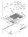
- FIG. 1 ashows a page of an assessment document with one or more student responses.
- FIG. 1 bshows the assessment document of FIG. 1 a separated into three layers of data, including a student response layer and two layers of preprinted text and graphics.
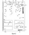
- FIG. 2shows a digitized representation of the student responses on the page.
- FIG. 3shows a typical networked system for implementing aspects of the present invention.
- FIG. 4shows a typical high-level block diagram of a process embodying aspects of the present invention.
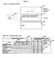
- FIG. 5 aschematically shows the storage of data comprising component layers, including the constructed response, the template, and the hint, which can be combined into a composite image.
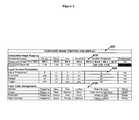
- FIG. 5 bis a table showing an embodiment of the invention utilizing four layers—background, constructed response, template, and hint—to create a 4-bit composite image.
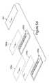
- FIG. 5 cshows three representations of a composite bit-mapped image, showing one, two, or three layers.
- FIG. 5 dshows the composite bit-mapped representations of FIG. 5 c , with the layers shown separated from one another.
- FIG. 6shows a series of color palettes used to selectively display the layers in the 4-bit image
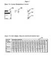
- FIG. 7shows an alternate series of color palettes used to selectively display the layers in the 4-bit image
- FIG. 8shows an embodiment utilizing 5 layers to create an 8-bit composite image
- FIG. 1 ashows a page of an assessment document ( 100 ) with a plurality of pre-printed materials including marks specifically to ensure proper scanning and identification ( 111 - 115 ), text to identify the form and the respondent ( 121 - 123 ), text and response areas for demographic data including name ( 131 ) and date of birth ( 132 ), text and item response areas for selected responses ( 141 - 143 ), text and response areas for survey-like questions ( 151 - 152 ), and text and response areas for two constructed response items ( 161 - 162 ).
- FIG. 1 afurther shows student responses including handwritten identifying information ( 122 a - 122 d ), both handwritten characters ( 131 a - 131 c and 132 a ) and completed OMR response targets ( 131 d - 131 f and 132 b ) for the demographic fields, responses to the selected response items ( 141 a - 143 b ), responses to the survey questions ( 151 a and 152 a ) and constructed responses to the two constructed response items ( 161 a and 162 a ).
- handwritten identifying information122 a - 122 d
- both handwritten characters131 a - 131 c and 132 a
- completed OMR response targets131 d - 131 f and 132 b
- FIG. 1 athere is additionally a student barcode label ( 170 ).
- FIG. 1 bshows the assessment document 100 separated into three layers of data, including a first layer 100 a of pre-printed text and graphics, a second layer 100 b of additional pre-printed text and graphics, and a third layer 100 c of student-made response marks.
- the different layersmay be in different colors to help distinguish the data presented in the different layers.
- the pre-printed text in layer 100 amay be shown in blue or black ink
- the pre-printed text in layer 100 bmay be shown in red ink
- the response marks in layer 100 cmay be shown in black or dark gray (as in pencil marks).
- FIG. 2shows a captured scanned image ( 200 ) of the page of an assessment document shown in FIG. 1 .
- pre-printed informationusing carbon ink, and student responses are captured, while pre-printed information using drop-out ink (or a drop-out color), that is, the data in layers 100 a and 100 b of FIG. 1 b , is not.
- drop-out inkor a drop-out color
- the plurality of pre-printed marks ( 111 ′- 115 ′) includedensure proper scanning and identification and appear in the captured image along with the text pre-printed in carbon ink ( 121 ′). Within the second constructed response, the portion preprinted in carbon ink is also captured ( 162 ′).
- All of the student responsesare captured including handwritten identifying information ( 122 a ′- 122 d ′), both handwritten characters ( 131 a ′- 131 c ′ and 132 a ′) and completed OMR response targets ( 131 d ′- 131 f ′ and 132 b ′) for the demographic fields, responses to the selected response items ( 141 a ′- 143 b ′), responses to the survey questions ( 151 a ′ and 152 a ′), and constructed responses to the two constructed response items ( 161 a ′ and 162 a ′).
- the printed information from the student barcodeis also captured ( 170 ′).
- FIG. 3shows a networked system suitable for an embodiment of the invention.
- a major function of the networked computer systemis to provide all of the images needed to build the composite image to be displayed.
- the captured student imageswill be unique to each document, but the other layers will often be fixed for all instances of each item.
- the appropriate assessment document ( 300 )is scanned by an image scanner ( 310 ), which, in turn, is attached to a computer ( 320 ).
- the captured digitized image of the student responseis stored within a file system of the computer or transmitted to another computer shown here as a server ( 330 ).
- the operatorcan interact with the scanning process using a computer monitor ( 321 ), keyboard ( 324 ) and mouse ( 325 ) in addition to the scanner itself.
- the remaining images for the different layerswill generally be created through other means and may be stored on the server ( 330 ) and/or pre-loaded into the reader's workstation ( 350 ).
- Such layerscan be created manually using image creation software, can be created directly from a digitized representation of the assessment document such as would be used to create the document, or other means that will be obvious to one skilled in the art of creating images.
- the composite imagecan be created, typically within the workstation ( 350 ) although the composite image could be created on some other system such as the server ( 330 ).
- the composite imagecan be displayed on the reader's monitor ( 351 ). Once displayed, the reader can assign a score to the displayed constructed response using a keyboard ( 354 ), mouse ( 355 ), or other appropriate control device. Alternatively, the reader can utilize a manipulation tool through the use of the keyboard, mouse, or other appropriate control device, to change the selection of displayed layers, change the colors of displayed colors, or other manipulations. Such other manipulations may include rotation of the displayed image, selection of a region of interest within the displayed image, or changing the zoom factor (alternatively known as the display factor) of the displayed image. Within such manipulations, changes in contrast, or brightness are achieved by manipulating the display colors so that none of the manipulations require changing the underlying image.
- FIG. 4shows a block diagram of one embodiment of the invention.
- the “pre-work” phase ( 400 )in which all of the needed images are created for each of the layers
- the “working” phase ( 450 )in which the composite images are built and displayed to a reader.
- the digitized representations of the constructed responsesare created by first scanning assessment documents ( 410 ) and then creating the captured images from the scanning process ( 411 ).
- the image captured by the scannerwill be sufficient while in others, additional processing will be needed to convert the scanned image to the needed digitized representation of the student response.
- additional processingmay involve extraction of student marks from a color image, selection of a region of interest, adjustment of the horizontal and/or vertical position of the image, adjustment of the horizontal and/or vertical stretch of the image, rotation of the image to adjust for skew, push-to white of very light marks, push to black of dark marks, normalization of the image colors or grayscale values, and/or other manipulations. Examples of such processing are described in Poor, U.S. Published Patent Application No. 2004-0126036 and Poor, U.S. Provisional Application No. 60/945,165, the respective disclosures of which are hereby incorporated by reference.
- additional imagesare created for the other layers.
- additional layersare static: for each item, there is one image for each additional layer and that one image will be used for all instances of that item, i.e., for all constructed responses to that item.
- a template( 420 ) which shows the pre-printed information on the form.
- a templatecan be created by scanning a blank form such that the pre-printed information is visible. If infra-red light is normally used for document scanning, the form can be scanned with visual spectrum light, as taught by McMillin (U.S. Pat. No. 5,103,490) (McMillin '490)—the disclosure of which is hereby incorporated by reference—to create the template.
- the templatecan be created programmatically from a digital representation of the assessment document such as might be used to produce the printed documents.
- Additional layersmay be used and the methods of creating appropriate images ( 430 ) may vary. For example, if a layer is designed to be a “hint”, the hint layer may be created by scanning a document which has the markings for the hint instead of a student constructed response. Alternatively, a hint can be created at the same time the document is designed. In this scenario, the hint context will not be exported as part of the printing or the template creation, but will be exported separately to create the hint image. Hint layers may also be directly created with graphic creation programs or even with word processing programs and then converted or “printed” to an image file. Similar processing options exist for many other potential layers such as mask layers and rubric layers.
- the second phase of FIG. 4shows how the images are used in the working phase ( 450 ), first by combining a subset of images into a layered composite image and then by displaying the composite image with appropriate display parameters to control which layers are displayed.
- the appropriate digitized image of a constructed responseis selected and read into the workstation memory.
- the images for the other layers that may be needed by the reader in order to properly score the itemare also needed in memory.
- all of the extra layer imagesare pre-loaded onto the workstation.
- each needed imageis read in from an appropriate repository as needed.
- images for additional layers that are neededare cached on the workstation after their first use so that they do not need to be retrieved when needed for another instance of a student constructed response for the same item.
- step ( 460 )Once all of the needed images are in the workstation, they are combined in step ( 460 ) into a single composite image. Specific bits within the pixels from each layer are assigned to specific bits within the composite image such that each bit location within the composite image corresponds to a specific layer.
- the composite imagecan be displayed to the reader.
- the displayoccurs immediately after the composite image is created.
- at least two composite imageswill be maintained so that the next composite image is ready as soon as the reader completes working on the currently displayed image.
- the display of the imagewill depend on specific display parameters, and default or initial values will be established before the first display of any composite image.
- Such display parametersmay include information such as region of interest, zooming factors, and the like, but will also include layer selection and color selection parameters. From these parameters, a custom palette of colors will be created ( 465 ) such that there is a color to be displayed for each possible bit pattern within the composite image. Then the composite image can be displayed ( 470 ) on an appropriate computer monitor or other display device using the color palette to determine the color used to display each pixel within the area of the composite image that is shown.
- a readerwill respond to a displayed composite image in one of two ways. Either the reader will be able to make an appropriate determination based on the displayed information, or the reader will need to adjust the display to reveal different information. In either case, the reader will typically provide some sort of input ( 475 ) using a device such as a keyboard, mouse, touch screen, or voice command.
- a devicesuch as a keyboard, mouse, touch screen, or voice command.
- the determined scoreis stored ( 490 ) and the process continues if there are additional items to be displayed.
- the inputwill typically be to do some manipulation of the image ( 475 ).
- Such manipulationmay include one or more of several manipulation functions including, but not limited to, selection of a subset of the displayed image, changing the layers that are displayed, rotating the image, flipping (mirror) of the image along the vertical center line, flipping of the image along the horizontal center line, changing the contrast or brightness of one or more layers, changing the set of colors used to display the different layers, changing the color used for the background, changing the set of colors used to display a specific layer, changing the zoom level of the image, changing the display characteristics within a selected area, or switching from whole image display to a region of interest.
- the manipulationscan be achieved without altering the underlying composite image, most of the manipulations are, in fact, implemented by merely changing the color palette.
- the paletteis built by ignoring the bit(s) associated with the layer to be suppressed. For example, consider an example for which there are only two layers, the student response and a “template” containing background context. To show both the template and the student response, pixels with student responses (with or without the template at the same location) are set to the appropriate student response color. Pixels with the template and without the student response are set to the template color. All other pixels are set to the background color. To suppress the template, the pixels with the template and without the student response are set to the background color. In practice, however, only the colors in the color palette are set as these colors map to the appropriate pixels within the image.
- Each entry in the color palettecorresponds to a combination or none or more layers.
- the entryis initially set to the background color and then the layers are examined in reverse priority.
- the entry coloris set to the appropriate layer color, thereby overriding any prior color.
- Additional image description parametersshould include the horizontal direction for rendering (left to right or right to left), the vertical direction for rendering (top to bottom or bottom to top).
- the rendered imagecan be manipulated (a) to show a “mirror” image (change the horizontal direction), (b) to “flip” the image upside-down (change the vertical direction), or (c) rotate the image 180° (change both).
- none of these manipulationsrequire changing the underlying image as these effects can be achieved through the description of the image and the use of a robust image display routine.
- a robust display routinecan support either.
- the “lines” of the imageare stored from top to bottom, while in others the lines are stored from the bottom to the top.
- a robust display routinecan support either. Therefore, by merely changing the horizontal direction (left to right and right to left), the displayed image will be a mirror image without any manipulation of the underlying image. Similarly, by changing the vertical direction (top to bottom and bottom to top), the displayed image will be “flipped”. By simultaneously changing both, the displayed image will be both a mirror image and flipped which is equivalent to rotating the image 180°, once again without changing the underlying image.
- ROIregion of interest
- This ROImay include some or all of the image.
- the parameters describing the area of the imagecan be changed without modifying the underlying image. If the display area is fixed, setting a small area of the total image to display will effectively “zoom in” to the specified area or ROI. By manipulating the ROI parameters, the user can effectively change the zoom level of the displayed image or the extent of the displayed image without changing the underlying image that is being displayed.
- a temporary derivative image based on the underlying imageneeds to be created with the appropriate manipulation applied.
- image display routinesutilize the lines and pixels (or columns) as defined within the stored image so temporary derivative images are required whenever the pixels in a displayed row are not all from the same row of the underlying image or whenever the pixels in a displayed column are not all from the same underlying image.
- the rows and columnsmust be redefined and an intermediate image must be created with the pixels reassigned to the new rows and the new columns.
- Display parametersmay contain a variety of parameters to support different manipulations including, but not limited to, the region of the composite image to be displayed, the horizontal direction of the image to be displayed (left to right or right to left), the vertical direction of the image to be displayed (top to bottom or bottom to top), the layers to be visible, the color or color set for each layer including the background, and the zoom level.
- the changes in the display of layers, colors, contrast, brightness, backgroundare all achieved by merely altering the appropriate entries within the custom color palette.
- the changing of the entries in the custom color paletteachieves results equivalent to building a color image one layer at a time but without the computationally intensive “conceptual” processing that follows.
- the equivalent conceptual processstarts by first creating a new image area setting all pixels to the background color. Then, the layers are each processed, one at a time. For each layer, each pixel is examined: if a pixel within the layer is ON, the corresponding pixel in the new image area is set to the selected color for that layer.
- Each entry in the custom color setcorresponds to a particular bit pattern and each bit pattern corresponds to the presence or absence of each layer. For each bit pattern, a color is assigned to show the highest priority displayed layer. If none of the “ON” bits within the pattern correspond to a displayed layer, the color entry is set to the background color. If the “ON” bits represent one or more displayed layers, the color entry is set to the color corresponding to the highest priority layer within the set represented by the “ON” bits.
- FIG. 5shows one embodiment of the invention using three layers such that each layer comprises a bitonal (black and white) 1-bit image and a 4-bit per pixel composite image.
- FIG. 5 ashows the three images ( 510 , 515 , 520 ) which are the component parts (i.e., layers) of the composite image and are stored in the Image Storage ( 440 ).
- the three imagesconsist of, respectively, the digitized representation of a single student's response ( 510 ), the template or mask for the item ( 515 ), and a “hint” showing the correct answer ( 520 ).
- FIG. 5 bshows how the pixels within the composite image can be created from the component images (on the left, 540 ), and then how the pixels within the composite image are mapped to different colors to create different displays for the reader (on the right, 560 ).
- each component layercomprises only a single bit for each pixel
- the composite image pixelcan be created by allocating a single bit within each composite image as shown ( 545 ). More generally, however, each component layer is not necessarily limited to one bit per pixel, but has fewer bits per pixel than the composite image, and the sum of the bits per pixel of all component layers must be less than or equal to the number of bits per pixel of the composite image.
- the low order bit (bit 0 ) of each composite image pixelis set to “1” if the corresponding pixel within the digitized constructed response image (i.e., the response layer) is black, and to “0” if the corresponding pixel within the digitized constructed response image is white.
- the next bit (bit 1 ) in each composite image pixelis set to “1” or “0” corresponding to the pixels in the template image (i.e., the template layer), and bit 2 in each in each composite image pixel is set to “1” or “0” corresponding to the pixels in the hint image (i.e., the hint layer).
- bit 3is unused and therefore always set to “0”.
- each pixel within the composite imageshows which component layers were white (0) or black (1).
- the first column ( 550 )there are seven possible values from none of the component layers being black (i.e., the background) to all three being black yielding values in the composite pixels ranging from 0 through 7 ( 555 ). That is, the value of the pixel is the numeric value of the binary combinations of 1's and 0's of the bits.
- an appropriate “color palette”can be constructed such as shown to the right ( 560 ).
- a color palettetypically specifies a specific color for each possible pixel value (or bit pattern) of an image.
- there are seven possible values for a composite pixel(0, 1, 2, 3, 4, 5, or 7), and thus there are seven colors (not necessarily unique) within the color palette.
- there could be eight possible values for a composite pixel(0, 1, 2, 3, 4, 5, 6, or 7) and thus eight colors within the color palette if having only the hint and template layers ON—a pixel value of 6—were an option.
- each setcorresponds to which layers (Response, Template, or Hint) will or will not be visible within the display.
- set 1only displays non-background colors for pixels which are included within the student response.
- Set 2displays non-background colors for pixels which are included within the student response or the template.
- Set 3displays non-background colors for pixels which are included within the student response, the template, or the hint.
- FIGS. 5 c and 5 dshow the same composite image as it would be displayed by the three sets of colors for the color palette ( 580 , 585 , 590 ). That is, referring back to FIG. 5 b , under ( 560 ), color set 1 corresponds to only the response being visible, color set 2 corresponds to the response and the template being visible, and color set 3 corresponds to the response, the template, and the hint being visible.
- Image 580 in FIGS. 5 c and 5 duses color set 1 , which specifies that any pixel for which bit 0 (the response bit) is ON (i.e., “1”) is visible, e.g., in black, and for all pixels in which bit 0 is not ON, those pixels are not visible, e.g., white. Accordingly, when color set 1 is specified for presentation of the composite image, only the response layer is visible.
- Image 585 in FIG. 5 cuses color set 2 from FIG. 5 b , which specifies that any pixel for which bit 0 (the response bit) is ON (i.e., “1”), the color of that pixel is a visible color, e.g., black, for any pixel for which only bit 1 (the template bit) is ON, the color of that pixel is a visible color, preferably a different color than the non-zero response pixels, e.g., blue, and for all pixels in which neither bit 0 or bit 1 is ON, the color of that pixel is white.
- the response and template layersare shown separately in FIG. 5 d , indicated by reference numbers 585 a and 585 b , respectively. Accordingly, when color set 2 is specified for presentation of the composite image, the response layer is visible and the template layer is visible, and the response and template layers are preferably different colors.
- Image 590 in FIG. 5 cuses color set 3 from FIG. 5 b .
- Any pixel for which bit 2 (the hint bit) is ONis visible, e.g., in red.
- Any pixel for which only bit 1 (the template bit) is ONis visible and preferably a different color than the non-zero hint pixels, e.g., blue.
- Any pixel for which only bit 0 (the response bit) is ON or only bits 0 and 1 are ONis visible and preferably a different color than the non-zero hint and template pixels, e.g., black.
- the color of that pixelis white (i.e., background).
- the response, hint, and template layersare shown separately in FIG. 5 d , indicated by reference numbers 590 a , 590 b , and 590 c , respectively. Accordingly, when color set 3 is specified for presentation of the composite image, the response layer, the template layer, and the hint layer are visible and each is preferably a different color. Moreover, should any non-background portion of the hint layer overlap a non-background portion of the response layer and/or the template layer, the hint layer would show up on top of the response or template, preferably in a different color than the response or template. Various combinations of response, hint, template, and background colors can be used.
- FIG. 6shows a table ( 600 ) representing a more complex embodiment of the invention with five different layers: Rubric, Mask, Hint, Template, and Student Response.
- the first layerderives from a grayscale image representation of a student response, either from a 4-bit grayscale representation or from the first high order 4 bits (i.e., bits 0 , 1 , 2 , 3 ) of an 8-bit grayscale representation.
- Each of the other four layersare 1-bit (bitonal) images. For purposes of explanation, it is assumed that 0 represents the absence of a mark.
- the five layersare combined into an 8-bit bitmapped image with each pixel within the composite image being derived from each of the five layers.
- the first section ( 610 ) of the table ( 600 ) in FIG. 6shows the mapping of the component layers into the composite image.
- the appropriate four bits from the digitized representation of the student responsei.e., the component, or constituent, image
- bits 0 - 3 of the composite imageFor each other layer, a single bit is set in each pixel of the composite image corresponding to the same pixel within the component layer image.
- each Template constituent image pixelcorresponds to bit 4 of the corresponding pixel of the composite image
- the bit of each Hint constituent image pixelcorresponds to bit 5 of the corresponding pixel of the composite image
- the bit of each Mask constituent image pixelcorresponds to bit 6 of the corresponding pixel of the composite image
- the bit of each Rubric constituent image pixelcorresponds to bit 7 of the corresponding pixel of the composite image.
- the second section ( 620 ) of the table ( 600 )shows exemplary layer control parameters that may be used to build the appropriate color palette.
- the control parametersare: Layer Precedence, Exclusive, Default, and Toggle (each of which will be described below). While there are many other parameters that might be used within a specific embodiment, many layer parameters will be similar to those shown:
- Layer PrecedenceIn the embodiment shown, colors from multiple layers at a given pixel are not blended, but a single color is selected for each pixel. When there are two or more layers present at a single pixel (i.e., the bits corresponding to two or more layers, or constituent images, are ON), the layer precedence parameter is used to select which color is to be displayed, with the selected color being from the layer with the highest precedence.
- the Exclusive parameterindicates when a specific layer's display effectively suppresses the display of all other layers. In the example, when the Rubric is shown (i.e., bit 7 of the composite image is ON), it is the only layer shown, regardless of which other layers may also be ON.
- the default parametersets the initial value for the layers to be displayed when a new composite item is first shown.
- the defaultmay be static or dynamically adjusted according to the item, the user, and/or the activities during the current and/or prior sessions. For example, a specific layer may initially be set to always be ON for a new image, but the user may change the default so that, in subsequent images, that same layer is OFF.
- the toggle parameterdetermines whether or not the user will be able to change the display setting for a given layer. In the current example, the user will not be able to turn off the mask or the student response layers.
- the third section ( 630 ) of table ( 600 )shows the color values assigned to each layer for four different sets of color values: Normal, Cream, Reversed, High Contrast.
- the pixelWhen there is no displayed layer at a specific pixel, the pixel will be shown in the background color, white, cream, black, or white, depending on the color set.
- the color selectedWhen there is one or more displayed layers at a specific pixel, the color selected will be the color corresponding to the displayed layer with the highest precedence value. If the color is selected from the student response layer, the color will be a function of the 4 bits of information within the composite image (values of 1-15).
- a better embodimentis to have flexible color values that depend on a “contrast” or “darkness” manipulation control as shown in FIG. 7 .
- a controlmay be dependent on audio input, keyboard entry, mouse movement or other input.
- appropriate controlsinclude, but are not limited to, a “pull down” set of choices ( 700 ), a numerical value ( 705 ), up and down controls ( 710 , 715 ) or a “slider” ( 720 ) as shown in FIG. 7 a .
- there are nine possible values for the contrast controlbut the number of possible selections may be more or less.
- FIG. 8shows one such implementation in which a demographic field from a scanned document is shown.
- this particular embodimentincludes several different layers, all of which derive from the scanned data. The first is the actual scanned marks ( 805 ), in this case letters and marks in Optical Mark Reading (OMR) targets. The second derived layer presents the darkness or “goodness of mark” for each OMR position ( 815 ).
- OMROptical Mark Reading
- the third derived layerpresents the text character extracted for each column within the matrix ( 820 ).
- the fourth layerpresents the text character extracted for each handwritten character based on Optical Character Recognition or Image Character Recognition (OCR or ICR) ( 825 ).
- OCR or ICROptical Character Recognition or Image Character Recognition
- the composite image with all layers shownis presented in FIG. 8 b ( 830 ), and each layer can be displayed in a different color.
- this inventionmay have little to offer over more conventional techniques in which multiple images are displayed in the same area.
- this inventionoffers a computationally efficient and responsive method to selectively present information from multiple constituent images.
Landscapes
- Engineering & Computer Science (AREA)
- Theoretical Computer Science (AREA)
- Business, Economics & Management (AREA)
- Physics & Mathematics (AREA)
- Educational Administration (AREA)
- Educational Technology (AREA)
- General Physics & Mathematics (AREA)
- Editing Of Facsimile Originals (AREA)
- Image Processing (AREA)
Abstract
Description
Claims (15)
Priority Applications (1)
| Application Number | Priority Date | Filing Date | Title |
|---|---|---|---|
| US11/931,067US8526766B2 (en) | 2007-10-31 | 2007-10-31 | Use of composite bitmapped images in conjunction with display of captured data |
Applications Claiming Priority (1)
| Application Number | Priority Date | Filing Date | Title |
|---|---|---|---|
| US11/931,067US8526766B2 (en) | 2007-10-31 | 2007-10-31 | Use of composite bitmapped images in conjunction with display of captured data |
Publications (2)
| Publication Number | Publication Date |
|---|---|
| US20090110270A1 US20090110270A1 (en) | 2009-04-30 |
| US8526766B2true US8526766B2 (en) | 2013-09-03 |
Family
ID=40582912
Family Applications (1)
| Application Number | Title | Priority Date | Filing Date |
|---|---|---|---|
| US11/931,067Active2032-07-03US8526766B2 (en) | 2007-10-31 | 2007-10-31 | Use of composite bitmapped images in conjunction with display of captured data |
Country Status (1)
| Country | Link |
|---|---|
| US (1) | US8526766B2 (en) |
Cited By (2)
| Publication number | Priority date | Publication date | Assignee | Title |
|---|---|---|---|---|
| US12307920B2 (en) | 2017-12-22 | 2025-05-20 | Knowledge Factor, Inc. | Display and report generation platform for testing results |
| US12444027B2 (en) | 2023-05-20 | 2025-10-14 | Earthcam Inc. | Processes to create a docu-narrative, including evidentiary quality images and evidentiary objects within the images, and an image chain of custody, with multi-level authentication and certification |
Families Citing this family (10)
| Publication number | Priority date | Publication date | Assignee | Title |
|---|---|---|---|---|
| US9218680B2 (en)* | 2010-09-01 | 2015-12-22 | K-Nfb Reading Technology, Inc. | Systems and methods for rendering graphical content and glyphs |
| US8593478B2 (en)* | 2010-10-19 | 2013-11-26 | Hewlett-Packard Development Company, L.P. | Extraction of a color palette model from an image of a document |
| US9099007B1 (en)* | 2011-05-15 | 2015-08-04 | Quaest, Inc. | Computerized processing of pictorial responses in evaluations |
| US8896896B2 (en) | 2011-09-13 | 2014-11-25 | Ricoh Production Print Solutions LLC | Preprinted form overlay |
| JP6010744B2 (en)* | 2012-05-31 | 2016-10-19 | 株式会社Pfu | Document creation system, document creation apparatus, document creation method, and program |
| US8860994B2 (en) | 2012-08-10 | 2014-10-14 | Ricoh Production Print Solutions | Electronic replacement of pre-printed forms |
| ES2817796T3 (en)* | 2012-12-07 | 2021-04-08 | Bae Systems Plc | Map display device and map display procedure |
| US9607524B2 (en)* | 2013-09-03 | 2017-03-28 | Xerox Corporation | Method and system for generating and evaluating assessment sheets |
| US9563957B1 (en)* | 2015-07-02 | 2017-02-07 | Yesvideo, Inc. | 2D/3D image scanning and compositing |
| US11410569B1 (en)* | 2018-11-13 | 2022-08-09 | Teacher Synergy LLC | Methods, systems, and media for identifying and scoring assignment answers |
Citations (68)
| Publication number | Priority date | Publication date | Assignee | Title |
|---|---|---|---|---|
| US4300123A (en) | 1979-01-02 | 1981-11-10 | Westinghouse Electric Corp. | Optical reading system |
| US4428733A (en)* | 1981-07-13 | 1984-01-31 | Kumar Misir Victor | Information gathering system |
| US4478584A (en) | 1983-08-26 | 1984-10-23 | Kathryn Kaney | Method for recording uncoded scores or ratings by multiple evaluators on a single automatic machine scannable document |
| US4708503A (en) | 1985-03-21 | 1987-11-24 | Meadowbrook Industries, Inc. | Work carrier for use in computer printing |
| US4760464A (en) | 1986-06-30 | 1988-07-26 | Ricoh Company, Ltd. | Shading correction system for image scanning apparatus |
| US4857715A (en) | 1988-04-01 | 1989-08-15 | National Computer Systems, Inc. | Overprint registration system for printing a customized survey form and scannable form therefor |
| US4937439A (en) | 1988-05-13 | 1990-06-26 | National Computer Systems, Inc. | Method and system for creating and scanning a customized survey form |
| US4978305A (en) | 1989-06-06 | 1990-12-18 | Educational Testing Service | Free response test grading method |
| US5001330A (en) | 1988-03-02 | 1991-03-19 | National Computer Systems, Inc. | Optically scanned document with fail-safe marking |
| US5001769A (en) | 1988-12-20 | 1991-03-19 | Educational Testing Service | Image processing system |
| US5004896A (en) | 1989-07-26 | 1991-04-02 | Educational Testing Service | Optical document scanning and mark sensing |
| US5011413A (en) | 1989-07-19 | 1991-04-30 | Educational Testing Service | Machine-interpretable figural response testing |
| US5085587A (en) | 1990-08-07 | 1992-02-04 | Scantron Corporation | Scannable form and system |
| US5099340A (en) | 1989-05-15 | 1992-03-24 | Sharp Kabushiki Kaisha | Electronic filing apparatus |
| US5103490A (en) | 1990-06-13 | 1992-04-07 | National Computer Systems, Inc. | Method and apparatus for storing and merging multiple optically scanned images |
| US5134669A (en) | 1990-06-13 | 1992-07-28 | National Computer Systems | Image processing system for documentary data |
| US5140139A (en) | 1989-11-13 | 1992-08-18 | Cognitronics Corporation | Preparing mark/read documents with markable boxes and locating the boxes from the document scan data |
| US5184003A (en) | 1989-12-04 | 1993-02-02 | National Computer Systems, Inc. | Scannable form having a control mark column with encoded data marks |
| US5194966A (en) | 1990-11-20 | 1993-03-16 | Educational Testing Service | Optical scanner threshold setting method and sheet |
| US5211564A (en) | 1989-07-19 | 1993-05-18 | Educational Testing Service | Computerized figural response testing system and method |
| US5218530A (en)* | 1989-09-11 | 1993-06-08 | Jastrzebski George B | Method of displaying and analyzing nonlinear, dynamic brain signals |
| US5291592A (en)* | 1989-05-15 | 1994-03-01 | Sharp Kabushiki Kaisha | System having document scanner for optically scanning information whereby a first information contains control information indicating a number of sheets to be scanned |
| US5318465A (en) | 1993-06-10 | 1994-06-07 | Burndy Corporation | Retention system with collapsible bridge |
| US5371673A (en) | 1987-04-06 | 1994-12-06 | Fan; David P. | Information processing analysis system for sorting and scoring text |
| US5420407A (en) | 1993-09-17 | 1995-05-30 | National Computer Systems, Inc. | Adjustable read level threshold for optical mark scanning |
| US5434931A (en) | 1991-07-12 | 1995-07-18 | Educational Testing Service | System and method for picture image processing employing transformation of picture data |
| US5452379A (en) | 1991-09-13 | 1995-09-19 | Meadowbrook Industries, Ltd. | Image capture and storage techniques in association with optical mark reading |
| US5664076A (en) | 1994-12-27 | 1997-09-02 | Karen A. Pluta | Apparatus and method for making a scannable form on a blank sheet |
| US5672060A (en) | 1992-07-08 | 1997-09-30 | Meadowbrook Industries, Ltd. | Apparatus and method for scoring nonobjective assessment materials through the application and use of captured images |
| US5869789A (en) | 1997-01-27 | 1999-02-09 | Educational Testing Service | Image digitizer with page number detector and recorder |
| US5873077A (en)* | 1995-01-13 | 1999-02-16 | Ricoh Corporation | Method and apparatus for searching for and retrieving documents using a facsimile machine |
| US5991595A (en) | 1997-03-21 | 1999-11-23 | Educational Testing Service | Computerized system for scoring constructed responses and methods for training, monitoring, and evaluating human rater's scoring of constructed responses |
| US6002794A (en)* | 1996-04-08 | 1999-12-14 | The Trustees Of Columbia University The City Of New York | Encoding and decoding of color digital image using wavelet and fractal encoding |
| US6079624A (en) | 1997-12-08 | 2000-06-27 | William C. Apperson | Data processing form using a scanning apparatus |
| US6166716A (en)* | 1997-12-26 | 2000-12-26 | Dentsu Tec Inc. | Presentation apparatus for two-dimensional picture information |
| US6173154B1 (en) | 1997-07-31 | 2001-01-09 | The Psychological Corporation | System and method for imaging test answer sheets having open-ended questions |
| US6176429B1 (en) | 1998-07-17 | 2001-01-23 | Psc Scanning, Inc. | Optical reader with selectable processing characteristics for reading data in multiple formats |
| US6256399B1 (en) | 1992-07-08 | 2001-07-03 | Ncs Pearson, Inc. | Method of distribution of digitized materials and control of scoring for open-ended assessments |
| US6282314B1 (en)* | 1994-09-08 | 2001-08-28 | Canon Kabushiki Kaisha | Image processing method and apparatus which iteratively divides image data into sub-regions |
| US6289125B1 (en) | 1994-01-20 | 2001-09-11 | Omron Corporation | Image processing device and method for indentifying an input image, and copier scanner and printer including same |
| US6295439B1 (en) | 1997-03-21 | 2001-09-25 | Educational Testing Service | Methods and systems for presentation and evaluation of constructed responses assessed by human evaluators |
| US6311040B1 (en) | 1997-07-31 | 2001-10-30 | The Psychological Corporation | System and method for scoring test answer sheets having open-ended questions |
| US20010046314A1 (en)* | 1997-03-28 | 2001-11-29 | Armando Neri | Method and device for controlling valuable or security items in particular banknotes |
| US6335805B1 (en) | 1996-12-17 | 2002-01-01 | Minolta Co., Ltd. | Image reading apparatus and method utilizing a plurality of line sensors |
| WO2002015170A2 (en) | 2000-08-11 | 2002-02-21 | Ctb/Mcgraw-Hill Llc | Enhanced data capture from imaged documents |
| US20020122606A1 (en) | 2001-03-05 | 2002-09-05 | Kristian Knowles | System for archiving electronic images of test question responses |
| US6459509B1 (en) | 1996-11-08 | 2002-10-01 | National Computer Systems, Inc. | Optical scanning device having a calibrated pixel output and a method for calibrating such a device |
| US6470100B2 (en)* | 1998-04-23 | 2002-10-22 | International Business Machines Corporation | Image composition processing apparatus and method thereof |
| US6532077B1 (en) | 1995-10-04 | 2003-03-11 | Canon Kabushiki Kaisha | Image processing system |
| US6556210B1 (en)* | 1998-05-29 | 2003-04-29 | Canon Kabushiki Kaisha | Image processing method and apparatus therefor |
| US6558166B1 (en) | 1993-02-05 | 2003-05-06 | Ncs Pearson, Inc. | Multiple data item scoring system and method |
| US20040021720A1 (en)* | 2002-07-30 | 2004-02-05 | Lluis Abello | Halftoning method and apparatus |
| US6704467B2 (en)* | 2000-12-21 | 2004-03-09 | Canon Kabushiki Kaisha | Image editing with block selection |
| US20040121298A1 (en) | 2002-11-06 | 2004-06-24 | Ctb/Mcgraw-Hill | System and method of capturing and processing hand-written responses in the administration of assessments |
| US20040150840A1 (en)* | 2003-01-30 | 2004-08-05 | Farrell Michael E. | Methods and systems for structuring a raster image file for parallel streaming rendering by multiple processors |
| US20040259067A1 (en) | 2003-05-16 | 2004-12-23 | Preston Cody | Method and system for receiving responses utilizing digital pen and paper |
| US6988895B1 (en) | 2001-01-12 | 2006-01-24 | Ncs Pearson, Inc. | Electronic test item display as an image with overlay controls |
| US7020435B2 (en) | 2003-06-12 | 2006-03-28 | Harcourt Assessment, Inc. | Electronic test answer record image quality improvement system and method |
| US20060115178A1 (en)* | 2004-11-30 | 2006-06-01 | Jian Fan | Artifact reduction in a digital video |
| US20060120605A1 (en) | 2004-12-08 | 2006-06-08 | Ctb/Mcgraw-Hill | Data extraction from temporal image data |
| US7095979B2 (en) | 2001-04-20 | 2006-08-22 | Educational Testing Service | Method of evaluation fit of raw data to model data |
| US20060187477A1 (en)* | 2004-02-27 | 2006-08-24 | Seiko Epson Corporation | Image processing system and image processing method |
| US7123764B2 (en) | 2000-11-08 | 2006-10-17 | Surface Logix Inc. | Image processing method for use in analyzing data of a chemotaxis or haptotaxis assay |
| US20070008564A1 (en) | 2005-07-06 | 2007-01-11 | Harcourt Assessment, Inc. | Image element alignment for printed matter and associated methods |
| US20070230810A1 (en)* | 2006-03-31 | 2007-10-04 | Canon Kabushiki Kaisha | Image-processing apparatus, image-processing method, and computer program used therewith |
| US20070273917A1 (en)* | 2003-09-10 | 2007-11-29 | Encrenaz Michel G | Methods, Apparatus and Software for Printing Location Pattern and Printed Materials |
| US20080042427A1 (en)* | 2003-12-16 | 2008-02-21 | Sani Muke | Security Article with Multicoloured Image |
| US20090067750A1 (en)* | 2007-08-31 | 2009-03-12 | Brice Pryszo | Chart display device and method for displaying chart |
- 2007
- 2007-10-31USUS11/931,067patent/US8526766B2/enactiveActive
Patent Citations (83)
| Publication number | Priority date | Publication date | Assignee | Title |
|---|---|---|---|---|
| US4300123A (en) | 1979-01-02 | 1981-11-10 | Westinghouse Electric Corp. | Optical reading system |
| US4428733A (en)* | 1981-07-13 | 1984-01-31 | Kumar Misir Victor | Information gathering system |
| US4478584A (en) | 1983-08-26 | 1984-10-23 | Kathryn Kaney | Method for recording uncoded scores or ratings by multiple evaluators on a single automatic machine scannable document |
| US4708503A (en) | 1985-03-21 | 1987-11-24 | Meadowbrook Industries, Inc. | Work carrier for use in computer printing |
| US4760464A (en) | 1986-06-30 | 1988-07-26 | Ricoh Company, Ltd. | Shading correction system for image scanning apparatus |
| US5371673A (en) | 1987-04-06 | 1994-12-06 | Fan; David P. | Information processing analysis system for sorting and scoring text |
| US5001330A (en) | 1988-03-02 | 1991-03-19 | National Computer Systems, Inc. | Optically scanned document with fail-safe marking |
| US4857715A (en) | 1988-04-01 | 1989-08-15 | National Computer Systems, Inc. | Overprint registration system for printing a customized survey form and scannable form therefor |
| US4937439A (en) | 1988-05-13 | 1990-06-26 | National Computer Systems, Inc. | Method and system for creating and scanning a customized survey form |
| US5001769A (en) | 1988-12-20 | 1991-03-19 | Educational Testing Service | Image processing system |
| US5291592A (en)* | 1989-05-15 | 1994-03-01 | Sharp Kabushiki Kaisha | System having document scanner for optically scanning information whereby a first information contains control information indicating a number of sheets to be scanned |
| US5099340A (en) | 1989-05-15 | 1992-03-24 | Sharp Kabushiki Kaisha | Electronic filing apparatus |
| US4978305A (en) | 1989-06-06 | 1990-12-18 | Educational Testing Service | Free response test grading method |
| US5011413A (en) | 1989-07-19 | 1991-04-30 | Educational Testing Service | Machine-interpretable figural response testing |
| US5211564A (en) | 1989-07-19 | 1993-05-18 | Educational Testing Service | Computerized figural response testing system and method |
| US5004896A (en) | 1989-07-26 | 1991-04-02 | Educational Testing Service | Optical document scanning and mark sensing |
| US5218530A (en)* | 1989-09-11 | 1993-06-08 | Jastrzebski George B | Method of displaying and analyzing nonlinear, dynamic brain signals |
| US5140139A (en) | 1989-11-13 | 1992-08-18 | Cognitronics Corporation | Preparing mark/read documents with markable boxes and locating the boxes from the document scan data |
| US5184003A (en) | 1989-12-04 | 1993-02-02 | National Computer Systems, Inc. | Scannable form having a control mark column with encoded data marks |
| US5134669A (en) | 1990-06-13 | 1992-07-28 | National Computer Systems | Image processing system for documentary data |
| US5103490A (en) | 1990-06-13 | 1992-04-07 | National Computer Systems, Inc. | Method and apparatus for storing and merging multiple optically scanned images |
| US5085587A (en) | 1990-08-07 | 1992-02-04 | Scantron Corporation | Scannable form and system |
| US5194966A (en) | 1990-11-20 | 1993-03-16 | Educational Testing Service | Optical scanner threshold setting method and sheet |
| US5434931A (en) | 1991-07-12 | 1995-07-18 | Educational Testing Service | System and method for picture image processing employing transformation of picture data |
| US5452379A (en) | 1991-09-13 | 1995-09-19 | Meadowbrook Industries, Ltd. | Image capture and storage techniques in association with optical mark reading |
| US20030086586A1 (en) | 1992-07-08 | 2003-05-08 | Ncs Pearson, Inc. | System and method of distribution of digitized materials and control of scoring for open-ended assessments |
| US6256399B1 (en) | 1992-07-08 | 2001-07-03 | Ncs Pearson, Inc. | Method of distribution of digitized materials and control of scoring for open-ended assessments |
| US7054464B2 (en) | 1992-07-08 | 2006-05-30 | Ncs Pearson, Inc. | System and method of distribution of digitized materials and control of scoring for open-ended assessments |
| US5672060A (en) | 1992-07-08 | 1997-09-30 | Meadowbrook Industries, Ltd. | Apparatus and method for scoring nonobjective assessment materials through the application and use of captured images |
| US6466683B1 (en) | 1992-07-08 | 2002-10-15 | Ncs Pearson, Inc. | System and method of distribution of digitized materials and control of scoring for open-ended assessments |
| US6558166B1 (en) | 1993-02-05 | 2003-05-06 | Ncs Pearson, Inc. | Multiple data item scoring system and method |
| US20040086841A1 (en) | 1993-02-05 | 2004-05-06 | Ncs Pearson, Inc. | Categorized data item reporting system and method |
| US5318465A (en) | 1993-06-10 | 1994-06-07 | Burndy Corporation | Retention system with collapsible bridge |
| US5711673A (en) | 1993-09-17 | 1998-01-27 | National Computer Systems | Method for interpreting a plurality of response marks on a scannable surface |
| US5420407A (en) | 1993-09-17 | 1995-05-30 | National Computer Systems, Inc. | Adjustable read level threshold for optical mark scanning |
| US6289125B1 (en) | 1994-01-20 | 2001-09-11 | Omron Corporation | Image processing device and method for indentifying an input image, and copier scanner and printer including same |
| US6282314B1 (en)* | 1994-09-08 | 2001-08-28 | Canon Kabushiki Kaisha | Image processing method and apparatus which iteratively divides image data into sub-regions |
| US5664076A (en) | 1994-12-27 | 1997-09-02 | Karen A. Pluta | Apparatus and method for making a scannable form on a blank sheet |
| US5873077A (en)* | 1995-01-13 | 1999-02-16 | Ricoh Corporation | Method and apparatus for searching for and retrieving documents using a facsimile machine |
| US6532077B1 (en) | 1995-10-04 | 2003-03-11 | Canon Kabushiki Kaisha | Image processing system |
| US6002794A (en)* | 1996-04-08 | 1999-12-14 | The Trustees Of Columbia University The City Of New York | Encoding and decoding of color digital image using wavelet and fractal encoding |
| US6459509B1 (en) | 1996-11-08 | 2002-10-01 | National Computer Systems, Inc. | Optical scanning device having a calibrated pixel output and a method for calibrating such a device |
| US6552829B1 (en) | 1996-11-08 | 2003-04-22 | Ncs Pearson, Inc. | Optical scanning device having a calibrated pixel output and method for calibrating such a device |
| US6335805B1 (en) | 1996-12-17 | 2002-01-01 | Minolta Co., Ltd. | Image reading apparatus and method utilizing a plurality of line sensors |
| US5869789A (en) | 1997-01-27 | 1999-02-09 | Educational Testing Service | Image digitizer with page number detector and recorder |
| US6295439B1 (en) | 1997-03-21 | 2001-09-25 | Educational Testing Service | Methods and systems for presentation and evaluation of constructed responses assessed by human evaluators |
| US5991595A (en) | 1997-03-21 | 1999-11-23 | Educational Testing Service | Computerized system for scoring constructed responses and methods for training, monitoring, and evaluating human rater's scoring of constructed responses |
| US6526258B2 (en) | 1997-03-21 | 2003-02-25 | Educational Testing Service | Methods and systems for presentation and evaluation of constructed responses assessed by human evaluators |
| US20010046314A1 (en)* | 1997-03-28 | 2001-11-29 | Armando Neri | Method and device for controlling valuable or security items in particular banknotes |
| US6684052B2 (en) | 1997-07-31 | 2004-01-27 | Harcourt Assessment, Inc. | Scanning system for imaging and storing the images of test answer sheets having open-ended questions |
| US20020110798A1 (en) | 1997-07-31 | 2002-08-15 | Bernard Kucinski | Method for imaging test answer sheets having open-ended questions |
| US6366760B1 (en) | 1997-07-31 | 2002-04-02 | The Psychological Corporation | Method for imaging test answer sheets having open-ended questions |
| US20040185424A1 (en) | 1997-07-31 | 2004-09-23 | Harcourt Assessment, Inc. | Method for scoring and delivering to a reader test answer images for open-ended questions |
| US6173154B1 (en) | 1997-07-31 | 2001-01-09 | The Psychological Corporation | System and method for imaging test answer sheets having open-ended questions |
| US6311040B1 (en) | 1997-07-31 | 2001-10-30 | The Psychological Corporation | System and method for scoring test answer sheets having open-ended questions |
| US6079624A (en) | 1997-12-08 | 2000-06-27 | William C. Apperson | Data processing form using a scanning apparatus |
| US6166716A (en)* | 1997-12-26 | 2000-12-26 | Dentsu Tec Inc. | Presentation apparatus for two-dimensional picture information |
| US6470100B2 (en)* | 1998-04-23 | 2002-10-22 | International Business Machines Corporation | Image composition processing apparatus and method thereof |
| US6556210B1 (en)* | 1998-05-29 | 2003-04-29 | Canon Kabushiki Kaisha | Image processing method and apparatus therefor |
| US6176429B1 (en) | 1998-07-17 | 2001-01-23 | Psc Scanning, Inc. | Optical reader with selectable processing characteristics for reading data in multiple formats |
| US20040131279A1 (en) | 2000-08-11 | 2004-07-08 | Poor David S | Enhanced data capture from imaged documents |
| US20040126036A1 (en) | 2000-08-11 | 2004-07-01 | Poor David D.S. | Method and apparatus for selective processing of captured images |
| WO2002015170A2 (en) | 2000-08-11 | 2002-02-21 | Ctb/Mcgraw-Hill Llc | Enhanced data capture from imaged documents |
| WO2002015558A2 (en) | 2000-08-11 | 2002-02-21 | Ctb/Mcgraw-Hill Llc | Method and apparatus for selective processing of captured images |
| US7123764B2 (en) | 2000-11-08 | 2006-10-17 | Surface Logix Inc. | Image processing method for use in analyzing data of a chemotaxis or haptotaxis assay |
| US6704467B2 (en)* | 2000-12-21 | 2004-03-09 | Canon Kabushiki Kaisha | Image editing with block selection |
| US6988895B1 (en) | 2001-01-12 | 2006-01-24 | Ncs Pearson, Inc. | Electronic test item display as an image with overlay controls |
| US20020122606A1 (en) | 2001-03-05 | 2002-09-05 | Kristian Knowles | System for archiving electronic images of test question responses |
| US6961482B2 (en) | 2001-03-05 | 2005-11-01 | Ncs Pearson, Inc. | System for archiving electronic images of test question responses |
| US7095979B2 (en) | 2001-04-20 | 2006-08-22 | Educational Testing Service | Method of evaluation fit of raw data to model data |
| US20040021720A1 (en)* | 2002-07-30 | 2004-02-05 | Lluis Abello | Halftoning method and apparatus |
| US20040121298A1 (en) | 2002-11-06 | 2004-06-24 | Ctb/Mcgraw-Hill | System and method of capturing and processing hand-written responses in the administration of assessments |
| US20040150840A1 (en)* | 2003-01-30 | 2004-08-05 | Farrell Michael E. | Methods and systems for structuring a raster image file for parallel streaming rendering by multiple processors |
| US20040259067A1 (en) | 2003-05-16 | 2004-12-23 | Preston Cody | Method and system for receiving responses utilizing digital pen and paper |
| US7020435B2 (en) | 2003-06-12 | 2006-03-28 | Harcourt Assessment, Inc. | Electronic test answer record image quality improvement system and method |
| US20070273917A1 (en)* | 2003-09-10 | 2007-11-29 | Encrenaz Michel G | Methods, Apparatus and Software for Printing Location Pattern and Printed Materials |
| US20080042427A1 (en)* | 2003-12-16 | 2008-02-21 | Sani Muke | Security Article with Multicoloured Image |
| US20060187477A1 (en)* | 2004-02-27 | 2006-08-24 | Seiko Epson Corporation | Image processing system and image processing method |
| US20060115178A1 (en)* | 2004-11-30 | 2006-06-01 | Jian Fan | Artifact reduction in a digital video |
| US20060120605A1 (en) | 2004-12-08 | 2006-06-08 | Ctb/Mcgraw-Hill | Data extraction from temporal image data |
| US20070008564A1 (en) | 2005-07-06 | 2007-01-11 | Harcourt Assessment, Inc. | Image element alignment for printed matter and associated methods |
| US20070230810A1 (en)* | 2006-03-31 | 2007-10-04 | Canon Kabushiki Kaisha | Image-processing apparatus, image-processing method, and computer program used therewith |
| US20090067750A1 (en)* | 2007-08-31 | 2009-03-12 | Brice Pryszo | Chart display device and method for displaying chart |
Non-Patent Citations (3)
| Title |
|---|
| Adobe Photoshop 7.0 Help, "Locking Layers", Mar. 2002.* |
| International Search Report for WO 2002-15170-A3, assigned to CTB/McGrawhill LLC, 3 pages. (Apr. 25, 2002). |
| International Search Report for WO 2002-15558-A3, assigned to CTB/McGrawhill LLC, 3 pages. (Aug. 29, 2002). |
Cited By (2)
| Publication number | Priority date | Publication date | Assignee | Title |
|---|---|---|---|---|
| US12307920B2 (en) | 2017-12-22 | 2025-05-20 | Knowledge Factor, Inc. | Display and report generation platform for testing results |
| US12444027B2 (en) | 2023-05-20 | 2025-10-14 | Earthcam Inc. | Processes to create a docu-narrative, including evidentiary quality images and evidentiary objects within the images, and an image chain of custody, with multi-level authentication and certification |
Also Published As
| Publication number | Publication date |
|---|---|
| US20090110270A1 (en) | 2009-04-30 |
Similar Documents
| Publication | Publication Date | Title |
|---|---|---|
| US8526766B2 (en) | Use of composite bitmapped images in conjunction with display of captured data | |
| US9336437B2 (en) | Segregation of handwritten information from typographic information on a document | |
| US7604161B2 (en) | Question paper forming apparatus and question paper forming method | |
| US20150187219A1 (en) | Systems and methods for computer-assisted grading of printed tests | |
| US20070031802A1 (en) | Educational material processing apparatus, educational material processing method, educational material processing program and computer-readable recording medium | |
| Kostelnick | A systematic approach to visual language in business communication | |
| US6970267B1 (en) | Gray scale optical mark reader | |
| Landoni | The Visual Book system: A study of the use of visual rhetoric in the design of electronic books | |
| Atanasiu et al. | Personalizing image enhancement for critical visual tasks: improved legibility of papyri using color processing and visual illusions | |
| US7606421B2 (en) | Data extraction from temporal image data | |
| Wright et al. | Colour cues as location aids in lengthy texts on screen and paper | |
| WO2018014774A1 (en) | Method for generating micro-graph group for information mapping and method for recognizing micro-graph group | |
| CN114926840A (en) | Method and system for transferring photocopy PDF (Portable document Format) to reproducible PDF | |
| JP2016114652A (en) | Training aid for character learning | |
| Elmer | Symbol considerations for bivariate thematic mapping | |
| Wilson et al. | Learn Adobe Illustrator CC for Graphic Design and Illustration: Adobe Certified Associate Exam Preparation | |
| Euler et al. | Visual display of qualitative information: Implications of using illustrations to depict video data | |
| Abu-Shaqra | Arabic Type Classification System-Qualitative Classification of Historic Arabic Writing Scripts in the Contemporary Typographic Context | |
| Horton | Top ten blunders by visual designers | |
| Yeung et al. | Effect of fidelity in diagram presentation | |
| Beriswill | Analysis-Based Message Design: Rethinking Screen Design Guidelines. | |
| Atanasiu et al. | Legibility Enhancement of Papyri Using Color Processing and Visual Illusions: A Case Study in Critical Vision | |
| Jogie | Adobe InDesign Masterclass: A comprehensive guide to taking your digital design skills from beginner to professional | |
| Collins | Paint | |
| Gordon et al. | Learn adobe InDesign CC for print and digital media publication: Adobe certified associate exam preparation |
Legal Events
| Date | Code | Title | Description |
|---|---|---|---|
| AS | Assignment | Owner name:CTB/MCGRAW-HILL LLC, CALIFORNIA Free format text:ASSIGNMENT OF ASSIGNORS INTEREST;ASSIGNOR:POOR, DAVID D.S., MR.;REEL/FRAME:020384/0651 Effective date:20071121 | |
| STCF | Information on status: patent grant | Free format text:PATENTED CASE | |
| AS | Assignment | Owner name:BANK OF MONTREAL, AS COLLATERAL AGENT, ILLINOIS Free format text:SECURITY AGREEMENT;ASSIGNORS:MCGRAW-HILL SCHOOL EDUCATION HOLDINGS, LLC;CTB/MCGRAW-HILL, LLC;GROW.NET, INC.;REEL/FRAME:032040/0330 Effective date:20131218 | |
| AS | Assignment | Owner name:MCGRAW-HILL SCHOOL EDUCATION HOLDINGS LLC, NEW YOR Free format text:ASSIGNMENT OF ASSIGNORS INTEREST;ASSIGNOR:CTB/MCGRAW-HILL LLC;REEL/FRAME:033232/0307 Effective date:20140630 | |
| AS | Assignment | Owner name:CTB/MCGRAW-HILL LLC, CALIFORNIA Free format text:ASSIGNMENT OF ASSIGNORS INTEREST;ASSIGNOR:MCGRAW-HILL SCHOOL EDUCATION HOLDINGS LLC;REEL/FRAME:036755/0610 Effective date:20150630 | |
| AS | Assignment | Owner name:DATA RECOGNITION CORPORATION, MINNESOTA Free format text:ASSIGNMENT OF ASSIGNORS INTEREST;ASSIGNOR:CTB/MCGRAW-HILL LLC;REEL/FRAME:036762/0940 Effective date:20150630 | |
| AS | Assignment | Owner name:MCGRAW-HILL SCHOOL EDUCATION HOLDINGS LLC, NEW YORK Free format text:ASSIGNMENT OF ASSIGNORS INTEREST;ASSIGNOR:DATA RECOGNITION CORPORATION;REEL/FRAME:036778/0662 Effective date:20150921 Owner name:MCGRAW-HILL SCHOOL EDUCATION HOLDINGS LLC, NEW YOR Free format text:ASSIGNMENT OF ASSIGNORS INTEREST;ASSIGNOR:DATA RECOGNITION CORPORATION;REEL/FRAME:036778/0662 Effective date:20150921 | |
| AS | Assignment | Owner name:CREDIT SUISSE AG, CAYMAN ISLANDS BRANCH, NEW YORK Free format text:PATENT SECURITY AGREEMENT;ASSIGNOR:MCGRAW-HILL SCHOOL EDUCATION HOLDINGS, LLC;REEL/FRAME:039205/0841 Effective date:20160504 Owner name:GROW.NET, INC., NEW YORK Free format text:RELEASE OF PATENT SECURITY AGREEMENT;ASSIGNOR:BANK OF MONTREAL;REEL/FRAME:039206/0035 Effective date:20160504 Owner name:MCGRAW-HILL SCHOOL EDUCATION HOLDINGS, LLC, NEW YO Free format text:RELEASE OF PATENT SECURITY AGREEMENT;ASSIGNOR:BANK OF MONTREAL;REEL/FRAME:039206/0035 Effective date:20160504 Owner name:CTB/MCGRAW-HILL LLC, CALIFORNIA Free format text:RELEASE OF PATENT SECURITY AGREEMENT;ASSIGNOR:BANK OF MONTREAL;REEL/FRAME:039206/0035 Effective date:20160504 | |
| FPAY | Fee payment | Year of fee payment:4 | |
| AS | Assignment | Owner name:CREDIT SUISSE AG, CAYMAN ISLANDS BRANCH, AS COLLAT Free format text:SECURITY INTEREST;ASSIGNOR:MCGRAW HILL LLC;REEL/FRAME:051402/0282 Effective date:20200101 Owner name:CREDIT SUISSE AG, CAYMAN ISLANDS BRANCH, AS COLLATERAL AGENT, NEW YORK Free format text:SECURITY INTEREST;ASSIGNOR:MCGRAW HILL LLC;REEL/FRAME:051402/0282 Effective date:20200101 | |
| AS | Assignment | Owner name:MCGRAW HILL LLC, NEW YORK Free format text:MERGER AND CHANGE OF NAME;ASSIGNORS:MCGRAW-HILL SCHOOL EDUCATION HOLDINGS, LLC;MCGRAW-HILL SCHOOL EDUCATION LLC;REEL/FRAME:051586/0564 Effective date:20191220 | |
| AS | Assignment | Owner name:MCGRAW HILL LLC, NEW YORK Free format text:CHANGE OF ASSIGNEE ADDRESS;ASSIGNOR:MCGRAW HILL LLC;REEL/FRAME:051723/0187 Effective date:20200128 | |
| AS | Assignment | Owner name:WILMINGTON TRUST, NATIONAL ASSOCIATION, AS COLLATERAL AGENT, MINNESOTA Free format text:SECURITY INTEREST;ASSIGNOR:MCGRAW HILL LLC;REEL/FRAME:055000/0643 Effective date:20210106 | |
| MAFP | Maintenance fee payment | Free format text:PAYMENT OF MAINTENANCE FEE, 8TH YEAR, LARGE ENTITY (ORIGINAL EVENT CODE: M1552); ENTITY STATUS OF PATENT OWNER: LARGE ENTITY Year of fee payment:8 | |
| AS | Assignment | Owner name:BANK OF AMERICA, N.A., NORTH CAROLINA Free format text:SECURITY AGREEMENT;ASSIGNOR:MCGRAW HILL LLC;REEL/FRAME:057041/0925 Effective date:20210730 Owner name:BANK OF AMERICA, N.A., NORTH CAROLINA Free format text:ABL SECURITY AGREEMENT;ASSIGNOR:MCGRAW HILL LLC;REEL/FRAME:057041/0934 Effective date:20210730 Owner name:THE BANK OF NEW YORK MELLON TRUST COMPANY, N.A., ILLINOIS Free format text:NOTES SECURITY AGREEMENT;ASSIGNOR:MCGRAW HILL LLC;REEL/FRAME:057041/0977 Effective date:20210730 | |
| AS | Assignment | Owner name:MCGRAW HILL LLC, NEW YORK Free format text:RELEASE BY SECURED PARTY;ASSIGNOR:WILMINGTON TRUST, NATIONAL ASSOCIATION;REEL/FRAME:057070/0283 Effective date:20210730 | |
| AS | Assignment | Owner name:MCGRAW HILL LLC (AS SUCCESSOR TO MCGRAW-HILL SCHOOL EDUCATION HOLDINGS, LLC), NEW YORK Free format text:RELEASE OF PATENT SECURITY AGREEMENT (FIRST LIEN);ASSIGNOR:CREDIT SUISSE AG, CAYMAN ISLANDS BRANCH, AS AGENT;REEL/FRAME:057263/0646 Effective date:20210730 Owner name:MCGRAW HILL LLC, NEW YORK Free format text:RELEASE OF PATENT SECURITY AGREEMENT (FIRST LIEN);ASSIGNOR:CREDIT SUISSE AG, CAYMAN ISLANDS BRANCH, AS AGENT;REEL/FRAME:057263/0664 Effective date:20210730 | |
| AS | Assignment | Owner name:THE BANK OF NEW YORK MELLON TRUST COMPANY, N.A., AS NOTES COLLATERAL AGENT, ILLINOIS Free format text:SECURITY INTEREST (NOTES);ASSIGNORS:ACHIEVE3000, INC.;ACTIVELY LEARN INC.;MCGRAW HILL LLC;REEL/FRAME:068522/0031 Effective date:20240806 | |
| MAFP | Maintenance fee payment | Free format text:PAYMENT OF MAINTENANCE FEE, 12TH YEAR, LARGE ENTITY (ORIGINAL EVENT CODE: M1553); ENTITY STATUS OF PATENT OWNER: LARGE ENTITY Year of fee payment:12 |