US8525683B2 - Method and system for locating and communicating with a user of a wireless communication device - Google Patents
Method and system for locating and communicating with a user of a wireless communication deviceDownload PDFInfo
- Publication number
- US8525683B2 US8525683B2US13/647,286US201213647286AUS8525683B2US 8525683 B2US8525683 B2US 8525683B2US 201213647286 AUS201213647286 AUS 201213647286AUS 8525683 B2US8525683 B2US 8525683B2
- Authority
- US
- United States
- Prior art keywords
- wireless communication
- communication device
- location
- wireless
- signal
- Prior art date
- Legal status (The legal status is an assumption and is not a legal conclusion. Google has not performed a legal analysis and makes no representation as to the accuracy of the status listed.)
- Expired - Fee Related
Links
- 238000004891communicationMethods0.000titleclaimsabstractdescription99
- 238000000034methodMethods0.000titleclaimsabstractdescription46
- 230000005540biological transmissionEffects0.000claimsdescription6
- 230000000007visual effectEffects0.000claimsdescription4
- 230000003213activating effectEffects0.000claimsdescription3
- 230000001413cellular effectEffects0.000claimsdescription3
- 230000010267cellular communicationEffects0.000claims1
- 230000003287optical effectEffects0.000claims1
- 241001465754MetazoaSpecies0.000description34
- 241001494479PecoraSpecies0.000description12
- 244000144980herdSpecies0.000description7
- 241000282472Canis lupus familiarisSpecies0.000description6
- 230000004044responseEffects0.000description6
- 230000008569processEffects0.000description5
- 238000010586diagramMethods0.000description4
- 230000006870functionEffects0.000description3
- 230000001010compromised effectEffects0.000description2
- 238000001514detection methodMethods0.000description2
- 206010012601diabetes mellitusDiseases0.000description2
- 230000033001locomotionEffects0.000description2
- 208000024827Alzheimer diseaseDiseases0.000description1
- 208000002230Diabetic comaDiseases0.000description1
- 208000027418Wounds and injuryDiseases0.000description1
- 230000002238attenuated effectEffects0.000description1
- 230000015572biosynthetic processEffects0.000description1
- 230000000981bystanderEffects0.000description1
- 230000008859changeEffects0.000description1
- 230000006378damageEffects0.000description1
- 230000007812deficiencyEffects0.000description1
- 230000009429distressEffects0.000description1
- 238000005516engineering processMethods0.000description1
- 230000036541healthEffects0.000description1
- 208000014674injuryDiseases0.000description1
- 230000002452interceptive effectEffects0.000description1
- 239000000463materialSubstances0.000description1
- 239000002184metalSubstances0.000description1
- 238000012544monitoring processMethods0.000description1
- 238000009304pastoral farmingMethods0.000description1
- 230000010363phase shiftEffects0.000description1
- 238000009877renderingMethods0.000description1
- 230000035945sensitivityEffects0.000description1
- 230000008054signal transmissionEffects0.000description1
- 230000035882stressEffects0.000description1
- 230000001755vocal effectEffects0.000description1
Images


Classifications
- G—PHYSICS
- G08—SIGNALLING
- G08B—SIGNALLING OR CALLING SYSTEMS; ORDER TELEGRAPHS; ALARM SYSTEMS
- G08B21/00—Alarms responsive to a single specified undesired or abnormal condition and not otherwise provided for
- G08B21/02—Alarms for ensuring the safety of persons
- G08B21/0202—Child monitoring systems using a transmitter-receiver system carried by the parent and the child
- G08B21/0266—System arrangements wherein the object is to detect the exact distance between parent and child or surveyor and item
- G—PHYSICS
- G08—SIGNALLING
- G08B—SIGNALLING OR CALLING SYSTEMS; ORDER TELEGRAPHS; ALARM SYSTEMS
- G08B21/00—Alarms responsive to a single specified undesired or abnormal condition and not otherwise provided for
- G08B21/18—Status alarms
- G08B21/22—Status alarms responsive to presence or absence of persons
- G—PHYSICS
- G08—SIGNALLING
- G08B—SIGNALLING OR CALLING SYSTEMS; ORDER TELEGRAPHS; ALARM SYSTEMS
- G08B21/00—Alarms responsive to a single specified undesired or abnormal condition and not otherwise provided for
- G08B21/02—Alarms for ensuring the safety of persons
Definitions
- Embodiments of the present inventiongenerally relate to wireless communication devices and more specifically to providing a wireless tether between two or more wireless communication devices.
- Prior art tracking and alarm systemssuch as exemplified in U.S. Pat. No. 5,731,785 disclose alarms and tracking systems that for the most part suffer from several deficiencies with regard to system failures, loss of signal, and adaptability to changing communication circumstances. For example, if a signal is lost between a tracking and alarm system transmitter and receiver due to transmission perturbations while within the operating range of the system, false alarms may occur.
- animal tethering devicesfor example, a wireless animal tether may work adequately to keep an animal within a particular radius about a transceiver, but if the wireless environment changes, the wireless tether may cause a false alarm condition unduly submitting the animal owner to undue stress.
- prior art wireless tethers used for animalsmay be configured to simply inflict pain to an animal once such an animal has exceeded a wireless boundary or the wireless signal is compromised.
- the communication link between the animal and transceivermay be lost thereby causing a false alarm even though the animal is within the radius causing pain and possibly injury to the animal.
- an animalmay be confused and may do anything it can to avoid the pain. Therefore, such animal may continue to move away from the boundary looking for relief thereby becoming further lost and perhaps a danger to others.
- Usersare located to determine if the user is located within, or has departed from, at least one bounded area established about a geographic location.
- the bounded areamay be defined by setting one or more distance boundaries from the geographic location.
- a base stationmay monitor the location of a wireless device in proximity of the user. If the wireless device departs from a bounded area, a message containing information configured to be understandable and convey meaning to the user and/or a third-party is sent to the wireless device and/or the third-party.
- the messagemay be configured to communicate to the user and/or third-party information pertaining to the departure from or entrance to the bounded area, location information, navigation directions, instructions, etc.
- the message sentmay include text and/or other symbols used to convey meaning to the user and/or the third party.
- FIG. 1is a top view illustrating one embodiment of an exemplar wireless tether apparatus in accordance with one or more aspects of the present invention.
- FIG. 2is a high-level schematic diagram of a wireless tether apparatus of FIG. 1 in accordance with one or more aspects of the present invention.
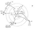
- FIG. 3is a high-level operational illustration of one embodiment of a wireless tether system in a base mode in accordance with one or more aspects of the present invention.
- FIG. 4is a high-level operational illustration of one embodiment of a wireless tether system in a chain-link configuration in accordance with one or more aspects of the present invention.
- FIG. 5is a high-level operational illustration of one embodiment of a wireless tether system in a group-link configuration in accordance with one or more aspects of the present invention.
- FIG. 6is flow diagram of one embodiment of a method of wirelessly tethering devices together in accordance with one or more aspects of the present invention.
- aspects of the present inventionare described in terms of communication system such as wireless telephonic communication systems, wireless communication systems such as defined in IEEE 802.11, and wireless networks such as Wireless Local Area Networks (WLAN).
- communication systemsuch as wireless telephonic communication systems, wireless communication systems such as defined in IEEE 802.11, and wireless networks such as Wireless Local Area Networks (WLAN).
- WLANWireless Local Area Networks
- the present inventionis not limited to any particular wireless communication system or network environment.
- the inventionmay be implemented as a computer program-product for use with a computer system.
- the programs defining the functions of at least one embodimentcan be provided to a computer via a variety of computer-readable media (i.e., signal-bearing medium), which include but are not limited to, (i) information permanently stored on non-writable storage media (e.g. read-only memory devices within a computer such as read only CD-ROM disks readable by a CD-ROM or DVD drive; (ii) alterable information stored on a writable storage media (e.g.
- FIG. 1is a top view illustrating one embodiment of an exemplar wireless tether apparatus 100 in accordance with one or more aspects of the present invention.
- Wireless tether apparatus 100includes body 102 .
- Body 102is made of a plurality of materials such as plastic, metal, and the like.
- Body 102includes direction displays 106 .
- Direction displays 106may be used to give direction to a user of wireless tether apparatus 100 .
- Direction displays 106may be of virtually any display type configured to indicate a direction.
- such direction displays 106may be a display monitor, a compass type display, and the like, configured to direct a user in a given direction.
- direction displays 106may include lights such as LEDs, and the like, to illuminate a direction.
- direction displays 106may output sound of vibration to direct a user such as a blind person.
- a low pitchmay emit that increases in pitch as a user moves wireless tether 100 in a predetermined direction.
- wireless tether apparatus 100includes an input device 110 and output device 114 .
- Input device 110can be any device adapted to give input to wireless tether 100 .
- a keyboard, keypad, light-pen, touch-screen, track-ball, or speech recognition unitcould be used.
- Output device 114is preferably any conventional display screen or speaker configured to provide information such as text, graphical displays, and the like, and may be integral with direction display 106 .
- Output device 114may also be a stereophonic device configured to provide stereophonic sound such as stereo, surround sound, and the like, to an animal or human user.
- the output deviceis a display screen of limited area, such as a display screen used on portable handheld devices.
- the output device 114 and input device 110could be combined.
- a display screen with an integrated touch-screen, and a display with an integrated keyboard, or a speech recognition unit combined with a text speech convertercould be used.
- FIG. 2is a high-level schematic diagram of one embodiment of a wireless tether apparatus 100 (i.e., wireless tether) of FIG. 1 in accordance with one or more aspects of the present invention.
- wireless tether 100includes antenna 202 coupled to a communication device 206 .
- Communication device 206may include a variety of various communication devices such as receivers, transmitters, transceivers, and the like, configured to receive and process communication signals.
- Communication device 206may be configured to process a plurality of wireless communication signals such as radio signals, light signals, infrared signals, and the like.
- Communication device 206may be configured to process a plurality of other types of wireless communication signals such as audible signals, vibration signals, and the like.
- Communication device 206is configured to output data in response to signals received thereto on data bus 210 . Such data may be of a plurality of data types such as digital data, analog data, and the like.
- Wireless tether apparatus 100includes data processing circuit 214 .
- data processing circuit 214includes clock device 226 , Central Processing Unit (CPU) 218 , and Location device 222 .
- Data processing circuit 214may be configured to receive and processes data from data bus 210 .
- Data processing circuit 214provides an output signal 224 to output device 114 .
- Data processing circuit 214receives an input signal 228 from input device 110 .
- Clock device 216may be configured using virtually any timing circuitry.
- clock device 216may include digital counter circuits configured to sequentially count in response to an oscillator circuit (not shown) coupled thereto.
- Location device 222may include a plurality of location determining circuits, for example, Location device 222 may include a compass, a global positioning system (GPS), triangulation circuitry, and the like. In one aspect, location device 222 utilizes one or more location determining circuits to ascertain location. Location device 222 may be configured to determine one or more directions of motion of wireless tether 100 relative a fixed direction such as magnetic north. Location device 222 may be configured to work independently of communication device 206 . For example, location device 222 may be a GPS receiver configured to receive and process GPS signals.
- GPSglobal positioning system
- data processing circuit 214is coupled to memory 240 via bus 238 .
- Memory 240is preferably random access memory sufficiently large to hold the necessary programming and data structures located on the wireless tether 100 . While memory 240 is shown as a single entity, it should be understood that memory 240 may in fact comprise a plurality of modules, and that memory 240 may exist at multiple levels, from high speed registers and caches to lower speed but larger DRAM chips.
- memory 240may include a tether program 254 that, when executed on CPU 218 , may provide information to a user of wireless tether 100 as described below.
- Tether program 254may be configured to provide a plurality of functions such as searching for tether communication signals, determining information to display, determining direction of travel, determining sound information, etc., described in more detail below.
- Tether program 254may use any one of a number of different programming languages.
- the program codecan be written in PLC code (e.g., ladder logic), a higher-level language such as C, C++, Java, or a number of other languages. While tether program 254 may be a standalone program, it is contemplated that tether program 254 may be combined with other programs.
- Memory 240may include a plurality of instructional data 256 .
- Instructional data 256may be used to provide meaningful instructions to a user of wireless tether 100 and someone in the proximity thereof. Instructions may be selected from a plurality of instructions and instruction types pertaining to a user or location. For example, for a lost young child instructions may include audio or visual messages such as “tell someone you are lost”, “ask for help”, “go back”, and the like. In another example, instructions may include advice to a medical patient who has had a memory lapse to return to a specific room number if they stray too far from the room. In one aspect, instructions may be designated messages for another party such as a bystander.
- wireless tether 100 used by the childmay emit instructions such as “help, I am lost” from output device 114 so others in proximity may hear the message. Instructions may be used to also convey a health condition. For example, if a diabetes patient were lost and was in a diabetic coma, wireless tether 100 may be configured to emit instructions such as “I am lost and have diabetes, call 911”. In one case, the instructions provided by wireless tether 100 may be in response to information from location device 222 to help the user return to within a predefined perimeter or location.
- wireless tether 100may provide information to a user such as “turn around” and then indicate “you are going in the right direction” when location device 222 determines the direction of the user's travel is in the correct direction. This may be especially important for people who may not be able to see the direction displays 106 .
- instructionsare described in terms of verbal or textual instructions, it is contemplated that instructions may be of virtually any form that conveys meaning to one or more users or systems responsive to such instructions.
- instructionsmay be in the form of alarms, sounds, displays, vibration sequences, and the like.
- Instructionmay also be in the form of graphical map displays and other types of map information that graphically conveys a location.
- wireless tether 100may obtain a plurality of instructional information such as maps from networks such as the Internet.
- instructional data 256may include audible instructions they understand. If the animal is used to a certain sound that reminds them to go to a specific location, the wireless tether 100 may emit one or more types of instructions to the animal to help direct such animal. For example, a wireless tether 100 may emit to a dog a prerecorded sound of the owner saying “Come home” recognized by such a dog as a command to come home. In one case, using output device 114 , surround sound may be used to help direct an animal as well by either providing a sound they want to avoid or move toward.
- wireless tether 100may emit a sound seemingly coming from the north of barking dogs which then may cause the sheep to go in a southern direction to avoid the barking dogs.
- the sound volume and configurationmay be adjusted accordingly to how urgently the animals need to move in a desired direction. For example, a very loud barking dog sound may be used to initiate a movement of sheep in a desired direction, and then be lowered as such sheep move in such a desired direction and distance.
- a desirable soundsuch as a dinner bell may be used as well to entice animals in a desired direction.
- wireless tether 100may be used to help keep the machine within a predefined distance of the base station without the use of external sensors used by the robot to keep within the designated area by providing instructions indicative of the tether boundary to the robot.
- Memory 240may include a plurality of configuration data 258 .
- Configuration data 258may be used to configure wireless tether 100 for operational modes examples of which are described below. While configuration data 258 is used generally to set a mode of operation input by a user of wireless tether 100 , configuration data 258 may be used to set other parameters not generally accessible to users.
- configuration datamay include GPS frequencies, radio station frequencies, communication scanning rates, and other types of communication information such data packet loss, bit error rate (BER), jitter, and the like.
- Memory 240may include a plurality of preset data 260 .
- Preset data 260may be used to configure wireless tether 100 for one or more operational modes examples of which are described below as default operational mode(s). This allows users to configure wireless tether 100 with one or more preferred default settings.
- FIG. 3is a high-level operational illustration of one embodiment of a wireless tether system 300 in a base configuration in accordance with one or more aspects of the present invention.
- wireless tether system 300illustrates only four wireless tethers 100 , however a plurality of wireless tethers 100 may be used.
- wireless tether 100is configured to a wireless tether transmitter 100 AT.
- Wireless tether transmitter 100 ATmay be configured to transmit one or more signals to at least one wireless tether 100 configured as a wireless tether receiver 100 RB-RD.
- wireless tether transmitter 100 ATis used as a base transmitter, e.g., base station.
- Wireless tether system 300may be configured to establish one or more wireless perimeters (three are shown) P 1 -P 3 extending from wireless tether transmitter 100 AT.
- perimeter P 2may be a boundary for wireless tether receivers 100 RB and 100 RC
- perimeter P 3may be a boundary for wireless tether receivers 100 RD, and so forth.
- Wireless tether receivers 100 RB-RDmay be configured to receive and respond to predetermined signals transmitted thereto.
- wireless tethers 100 RB-RDprovide one or more external responses such as vibration and sound to signal users thereof if communication exceeds distance thresholds from wireless tether receiver 100 AT.
- clock device 226may be used to establish time references for virtually any mode of operation some of which are described herein.
- perimeter P 1may be adjusted to different perimeter values over time.
- time modemay be used to shrink perimeter P 1 to a smaller value over time such that the children eventually arrive back at the base station unit 100 AT at predetermined time. This may be especially useful where a group is given more freedom to roam farther apart at one time but needs to be closer together at a different time.
- timemay be used to change modes of operation as desired.
- time modemay be set such that one-way communication is used for a predetermined time and then is set to two-way communication.
- a hikeris using one-way mode to help them keep within a given area
- a wireless tether 100may be set to two-way communication mode so that the base station can make sure that the hiker is still within a predetermined area.
- Time modemay be configured such that wireless tether 100 has different response rates as desired for one or more modes of operation.
- Time modeallows a user to set the sensitivity of operation to further avoid false alarms. For example, consider the case were a teenager has gone outside a given perimeter P 1 . Time mode may be set to allow the teenager to travel back into perimeter P 1 before activating other more severe alerts such as a distress alert or alert a base station such as wireless transmitter 100 AT.
- perimeters P 1 -P 3may be set such that when at least one wireless tether 100 RB-RD passes at least one boundary P 1 -P 3 , a warning alert may be provided therefrom.
- wireless tether receiver 100 RCmay be set to stay within perimeter P 2 .
- wireless tether receiver 100 RCprovides an alert when it is positioned beyond perimeter P 2 .
- Such an alertmay instruct a user of wireless tether receiver 100 RC that a perimeter P 2 has been exceeded. In this case, such a user may not be lost but rather has gone beyond a predetermined distance from wireless tether transmitter 100 AT, e.g., P 2 .
- the warningmay be a series of directional tones or sounds they understand. For example, consider the case where a herd of sheep are wandering together and go beyond a specific part of the grassland that the sheep owner wants them to stay within without using fences. A directional tone or sound could be used to direct sheep within a specified area and direction of travel.
- one or more wireless tether receivers 100 RB-RDmay be set to transmit alert signals to wireless tether transmitter 100 AT and other receivers in proximity thereto.
- radio receiver 322is in reception range of wireless tether receiver 100 RC.
- wireless tether receiver 100 RCexceeds a predetermined perimeter, e.g., P 1 -P 3
- wireless tether receiver 100 RCmay be configured to send an alert using a plurality of frequencies associated with radios such as AM radios, FM radios, and the like, to alert users of such radios that wireless receiver 100 RC has exceeded a boundary threshold.
- transmit alert modemay allow others to join in such a search and rescue operation that normally would not know or be part of such a search and rescue operation.
- one or more wireless tether receivers 100 RB-RDmay be set to receive signals from other transmitters in addition to wireless tether transmitter 100 AT.
- wireless tether receivers 100 RB and 100 RDmay be configured to receive signals from transmitter 308 and satellite 304 respectively.
- Transmitter 308may be virtually any type of transmitter configured to communicate with wireless tether receivers 100 RB-RD.
- transmitter 308may be a cellular transmitter, microwave transmitter, FM radio transmitter, AM radio transmitter, WAN wireless link, wireless transmitters configured to wireless standards such as IEEE 802.11, and the like.
- alternative transmittersmay be used to expand one or more perimeters P 1 -P 3 outside wireless tether transmitter 100 AT range.
- wireless tether transmitter 100 ATmay have a limited range due to local terrain, e.g. a mountainous region.
- Transmitter 308may be configured to broadcast tether signals to one or more wireless receivers 100 RB-RD.
- satellite 304may be used to cover an even wider range due to its location in space.
- wireless tether receivers 100 RB-RDwhen wireless tether receivers 100 RB-RD are outside their predetermined perimeters external communication systems such as transmitter 308 and satellite 304 may be used.
- wireless tether receivers 100 RB-RDmay be configured to send a different set of instructions to wireless tether users. For example, when a tether user leaves a predefined perimeter or travels beyond a range of wireless tether transmitter 100 AT, wireless tether receivers 100 RB-RD may receive other tether signals from transmitter 308 and satellite 304 . Once outside such predefined perimeters, one or more wireless tether receivers 100 RB-RD are responsive to such transmitter 308 and satellite 304 signals.
- a wireless tether 100 RB-RDis providing instructions to a user to go back towards wireless tether transmitter 100 AT
- new instructionsmay be provided to such a user instructing the user to go in the same direction, or in a new direction, etc. This is especially useful when a user for example wanders outside a range of wireless tether transmitter 100 AT but is in range of another transmitter such as transmitter 308 .
- satellite 304may be a GPS satellite and transmit GPS signals
- wireless tether receivers 100 RB-RDmay use such GPS signals to instruct users to do different actions such as walk toward a landmark.
- a wireless tether receivers 100 RB-RDmay provide such a tether user instructions to move in the direction of such a ranger station.
- Wireless tether receivers 100 RB-RDmay also provide additional instructions to such a user thereof if a transmitter 308 is in two-way communication.
- wireless tether receiver 100 RB-RDmay provide a tether user instructions such as “stay put”, “find shelter”, and so forth, or even may allow such third party and tether user to communicate directly through input device 110 and output device 114 .
- At least one wireless tether receivers 100 RB-RDmay be configured to scan for different tether signal frequencies and types of tether signals.
- Tether signalsmay include a plurality of wireless communication signals such as radio signals, light signals, infrared signals, and the like.
- at least one wireless tether receiver 100 RB-RDmay scan to find such other forms of wireless communication signals. Scan mode is especially useful to minimize false alarms. For example, if a first Radio Frequency (RF) is being attenuated due to environment, another frequency less affected by the environment may be used. Similarly, different types of tether signals may be scanned for and used.
- RFRadio Frequency
- wireless tether receivers 100 RB-RDmay scan for other tether signal transmissions transmitted from other transmitters such as transmitter 308 and satellite 304 .
- FIG. 4is a high-level operational illustration of one embodiment of a wireless tether system 400 in a chain-link configuration in accordance with one or more aspects of the present invention.
- each wireless tether receivers 100 RA-RDare configured as a transceiver in communication with at least one other wireless tether receivers 100 RA-RD.
- Chain-link modeallows one or more wireless tether receivers 100 RA-RD to be coupled in a chain such that distances between communicating pairs of wireless tether receivers 100 RA-RD is less than an overall distance allowable by a group of wireless tether receivers 100 RA-RD. As illustrated in FIG.
- wireless tether receiver 100 RAis in communication to wireless tether receiver 100 RB; wireless tether receiver 100 RB is in communication with wireless tether receiver 100 RC; and wireless tether receiver 100 RC is in communication with wireless tether receiver 100 RD.
- Each communicating pair of wireless tether receivers 100 RA-RDhave a perimeter PA-C defining a predefined distance apart. For example, a perimeter between wireless tether receiver 100 RA and wireless tether receiver 100 RB is PA.
- each wireless tether receiver 100 RA-RDwere aligned such that communicating pairs were in a single line, e.g., wireless tether receiver 100 RA then wireless tether receiver 100 RB, then wireless tether receiver 100 RC, then wireless tether receiver 100 RD, the overall distance between wireless tether receiver 100 RA and wireless tether receiver 100 RD is greater than any one of perimeters PA-C.
- perimeters PA-Cmay be configured with different perimeters such as shown in FIG. 3 , to provide preset distance thresholds. For example, if each communicating pair had an inner perimeter and outer perimeter threshold, an alert may be provided by a wireless tether receiver 100 RA-RD when a rescuer moves too close or too far from another rescuer and violates either perimeter threshold.
- PA-C instructionswill be provided to a user. For example as illustrated in FIG. 4 , if wireless tether receiver 100 RD moves beyond perimeter PC, an alert will be provided to user of wireless tether receiver 100 RD.
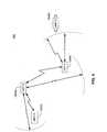
- FIG. 5is a high-level operational illustration of one embodiment of a wireless tether system 500 in a group-link configuration in accordance with one or more aspects of the present invention.
- one or more wireless tether receivers 100 RB-RDare in communication with each other forming a wireless tether group 502 .
- Wireless tether group 502may communicate via one or more wireless tether receivers 100 RB-RD to wireless tether transmitter 100 AT.
- wireless tether transmitter 100 ATis in communication with wireless tether group 502 via tether signal 504 .
- group-link configuration 500may be configured such that wireless tether receivers 100 RB-RD are configured to only receive tether signals from wireless tether group 502 and wireless tether transmitter 100 AT, or may be configured for two-way communication to each other and wireless tether transmitter 100 AT.
- wireless tether group 502has at least one predetermined group perimeter P-G from wireless tether transmitter 100 AT.
- each wireless tether 100has their own perimeter associated with one or more other wireless tethers 100 defining such a wireless tether group 502 .
- wireless tether receiver 100 RBis in communication with wireless tether receiver 100 RC via tether signal 506
- wireless tether receiver 100 RCis in communication with wireless receiver 100 RD via tether signal 508
- the maximum distance apart between wireless tether receiver 100 RB and wireless tether receiver 100 RCis P-B.
- the maximum distance apart between wireless tether receiver 100 RC and wireless tether receiver 100 RDis P-C.
- at least one wireless tether receiver 100 RB-RDremain within P-G wireless tether group 502 may move about freely within their respective perimeters P-B and P-D.
- the maximum distance apart that the group may strayis similar to chain-link mode when wireless tether receivers 100 RB-RD are about in a straight-line relative wireless tether transmitter 100 AT.
- the wireless tether group 502may be used to herd animals.
- a directional tone or soundcould be used to direct such herd of sheep within a predetermined group perimeter P-G.
- the group perimeter P-Gmay be adjusted over time using time mode described herein to slowly corral sheep within a final group perimeter P-G.
- animals such as sheepcould be moved from place to place by assigning a different wireless tether transmitter 100 AT- 1 to wireless tether group 502 .
- wireless tether receivers 100 RB-RDmay act as “wireless” sheep dogs helping to dynamically herd animals into a plurality of predetermined grazing locations while maintaining a predetermined herd formation size.
- group statusmay be shared by some or all members of the wireless tether group 502 .
- a member of wireless tether group 502goes beyond its predetermined perimeter, e.g., P-B, members of wireless tether group 502 are alerted and the straying member of wireless tether group 502 may be given instructions such as “return to the group”.
- each wireless tether receivers 100 RB-RD of wireless tether group 502is relayed from the wireless tether receivers 100 RB-RD outside P-G though the at least one wireless tether receivers 100 RB-RD within group perimeter P-G.
- base stationi.e., wireless tether transmitter 100 AT
- such a straying membermay be giving similar instructions as above such as “return to the group”.
- group-link configuration 500is used to assign an overall group perimeter P-G to a group of wireless tether receivers 100 RB-RD where each member of wireless tether group 502 is also required to maintain a preset distance from one or more members of wireless tether group 502 , e.g., P-B.
- a mode of operationmay be especially useful when a group such as travelers, for example, need to be kept together as they travel from a base area such as a base camp. This mode may also be useful to keep a herd of animals together and moving a desired direction.
- FIG. 6is flow diagram of one embodiment of a method 600 of wirelessly tethering devices together in accordance with one or more aspects of the present invention.
- Method 600is entered into when for example two or more wireless tether devices 100 are establishing a communication link.
- method 600determines if a base mode has been set to establish one or more base stations as illustrated in FIG. 3 for example. If a base mode is not set, then at 614 link-mode is set to establish a link between tether devices such as shown in FIG. 4 and method 600 proceeds to 610 . If at 606 , a base mode is set then at 610 a check for one-way communication is made. If communication has been set to one way then method 600 proceeds to 622 described below. If, however, two-way communication is required, then at 610 method 600 moves to 618 and sets two-way communication mode.
- communication thresholdsare established. For example, for a wireless tether receiver configuration, communication detection would be the reception of one or more wireless tether signals. For two-way communication, communication detection may include detecting corresponding two-way communication using techniques such as handshake protocols, and the like.
- distance thresholdsare checked, i.e. distance perimeters. If threshold is maintained, then method 600 returns to 622 . If however, at least one distance threshold is not maintained, then at 626 method 600 attempts to determine if at least one perimeter threshold has been exceeded, or if communication has been compromised. Distance thresholds may be determined in a number of ways such as signal strength, Doppler, pulse modulation time differential, phase shifts, and other distance determining methods as are known in the art.
- communicationmay be tested and re-established in a plurality of ways. For example, if tether signals are lost, signal scanning as described above may be used to re-establish a signal connection.
- re-establishment of one or more distance thresholdsis checked. If one or more distance thresholds are re-established, method 600 proceeds to 622 . If one or more distance thresholds are not re-established then method 600 proceeds to 634 .
- informationis provided in response to the inability to reestablish distance threshold. For example, a user moves beyond a predefined perimeter from a base unit (e.g., see FIG.
- a signalmay be given to the user from the wireless tether receiver 100 indicative thereof.
- tether terminationis checked for at 638 . If tether termination has occurred, then method 600 moves to 642 and ends. If however, tether was not terminated then method 600 proceeds to 622 .
Landscapes
- Business, Economics & Management (AREA)
- Emergency Management (AREA)
- Physics & Mathematics (AREA)
- General Physics & Mathematics (AREA)
- Health & Medical Sciences (AREA)
- Child & Adolescent Psychology (AREA)
- General Health & Medical Sciences (AREA)
- Mobile Radio Communication Systems (AREA)
- Alarm Systems (AREA)
- Telephone Function (AREA)
Abstract
Description
Maximum Overall Distance=PA+PB+PC (1)
Claims (28)
Priority Applications (3)
| Application Number | Priority Date | Filing Date | Title |
|---|---|---|---|
| US13/647,286US8525683B2 (en) | 2003-09-06 | 2012-10-08 | Method and system for locating and communicating with a user of a wireless communication device |
| US14/015,399US8890695B2 (en) | 2003-09-06 | 2013-08-30 | Method and system for locating and communicating with a user of a wireless communication device |
| US14/543,778US20150070176A1 (en) | 2003-09-06 | 2014-11-17 | System and method for wirelessly tethering one or more machines |
Applications Claiming Priority (6)
| Application Number | Priority Date | Filing Date | Title |
|---|---|---|---|
| US10/655,788US7061385B2 (en) | 2003-09-06 | 2003-09-06 | Method and apparatus for a wireless tether system |
| US11/336,109US7312711B2 (en) | 2003-09-06 | 2006-01-20 | Method and apparatus for a wireless tether system |
| US11/983,948US7535369B2 (en) | 2006-01-20 | 2007-11-13 | Method and apparatus for a wireless tether system |
| US12/454,107US7944359B2 (en) | 2003-09-06 | 2009-05-12 | Method and apparatus for a wireless tether system |
| US13/083,554US8368546B2 (en) | 2003-09-06 | 2011-04-09 | Method and system for locating and communicating with a user of a wireless communication device |
| US13/647,286US8525683B2 (en) | 2003-09-06 | 2012-10-08 | Method and system for locating and communicating with a user of a wireless communication device |
Related Parent Applications (1)
| Application Number | Title | Priority Date | Filing Date |
|---|---|---|---|
| US13/083,554ContinuationUS8368546B2 (en) | 2003-09-06 | 2011-04-09 | Method and system for locating and communicating with a user of a wireless communication device |
Related Child Applications (1)
| Application Number | Title | Priority Date | Filing Date |
|---|---|---|---|
| US14/015,399ContinuationUS8890695B2 (en) | 2003-09-06 | 2013-08-30 | Method and system for locating and communicating with a user of a wireless communication device |
Publications (2)
| Publication Number | Publication Date |
|---|---|
| US20130029694A1 US20130029694A1 (en) | 2013-01-31 |
| US8525683B2true US8525683B2 (en) | 2013-09-03 |
Family
ID=39169017
Family Applications (7)
| Application Number | Title | Priority Date | Filing Date |
|---|---|---|---|
| US11/983,948CeasedUS7535369B2 (en) | 2003-09-06 | 2007-11-13 | Method and apparatus for a wireless tether system |
| US12/454,107Expired - Fee RelatedUS7944359B2 (en) | 2003-09-06 | 2009-05-12 | Method and apparatus for a wireless tether system |
| US13/083,554Expired - Fee RelatedUS8368546B2 (en) | 2003-09-06 | 2011-04-09 | Method and system for locating and communicating with a user of a wireless communication device |
| US13/647,304Expired - Fee RelatedUS8525684B2 (en) | 2003-09-06 | 2012-10-08 | Method and system for locating and communicating with a user of a wireless communication device |
| US13/647,286Expired - Fee RelatedUS8525683B2 (en) | 2003-09-06 | 2012-10-08 | Method and system for locating and communicating with a user of a wireless communication device |
| US14/015,399Expired - Fee RelatedUS8890695B2 (en) | 2003-09-06 | 2013-08-30 | Method and system for locating and communicating with a user of a wireless communication device |
| US14/543,778AbandonedUS20150070176A1 (en) | 2003-09-06 | 2014-11-17 | System and method for wirelessly tethering one or more machines |
Family Applications Before (4)
| Application Number | Title | Priority Date | Filing Date |
|---|---|---|---|
| US11/983,948CeasedUS7535369B2 (en) | 2003-09-06 | 2007-11-13 | Method and apparatus for a wireless tether system |
| US12/454,107Expired - Fee RelatedUS7944359B2 (en) | 2003-09-06 | 2009-05-12 | Method and apparatus for a wireless tether system |
| US13/083,554Expired - Fee RelatedUS8368546B2 (en) | 2003-09-06 | 2011-04-09 | Method and system for locating and communicating with a user of a wireless communication device |
| US13/647,304Expired - Fee RelatedUS8525684B2 (en) | 2003-09-06 | 2012-10-08 | Method and system for locating and communicating with a user of a wireless communication device |
Family Applications After (2)
| Application Number | Title | Priority Date | Filing Date |
|---|---|---|---|
| US14/015,399Expired - Fee RelatedUS8890695B2 (en) | 2003-09-06 | 2013-08-30 | Method and system for locating and communicating with a user of a wireless communication device |
| US14/543,778AbandonedUS20150070176A1 (en) | 2003-09-06 | 2014-11-17 | System and method for wirelessly tethering one or more machines |
Country Status (1)
| Country | Link |
|---|---|
| US (7) | US7535369B2 (en) |
Cited By (2)
| Publication number | Priority date | Publication date | Assignee | Title |
|---|---|---|---|---|
| US8890695B2 (en)* | 2003-09-06 | 2014-11-18 | TV-Tether, LLC | Method and system for locating and communicating with a user of a wireless communication device |
| US9002379B1 (en) | 2014-02-24 | 2015-04-07 | Appsurdity, Inc. | Groups surrounding a present geo-spatial location of a mobile device |
Families Citing this family (51)
| Publication number | Priority date | Publication date | Assignee | Title |
|---|---|---|---|---|
| WO2009057182A1 (en)* | 2007-10-30 | 2009-05-07 | Fujitsu Limited | System for preventing property from being left, method for preventing property from being left, and mobile terminal |
| US20090322535A1 (en)* | 2008-06-30 | 2009-12-31 | Ji Shin | Car security system |
| GB2466827A (en)* | 2009-01-12 | 2010-07-14 | Matthew Wellings | Alarm detecting missing objects from a group using wireless communications |
| US8335519B2 (en)* | 2009-12-03 | 2012-12-18 | Osocad Remote Limited Liability Company | System and method for providing a community of mobile devices |
| US8976724B2 (en) | 2010-04-20 | 2015-03-10 | Zomm, Llc | Method and system for repackaging wireless data |
| US11470814B2 (en) | 2011-12-05 | 2022-10-18 | Radio Systems Corporation | Piezoelectric detection coupling of a bark collar |
| US10674709B2 (en) | 2011-12-05 | 2020-06-09 | Radio Systems Corporation | Piezoelectric detection coupling of a bark collar |
| US11553692B2 (en) | 2011-12-05 | 2023-01-17 | Radio Systems Corporation | Piezoelectric detection coupling of a bark collar |
| US9799185B2 (en)* | 2012-04-13 | 2017-10-24 | Gordon Jessop | Method, device, and computer program for mobile asset tracking |
| US9317996B2 (en) | 2012-06-22 | 2016-04-19 | II Robert L. Pierce | Method for authenticating a wager using a system and method for interacting with virtual geographic zones |
| US10360760B2 (en) | 2012-06-22 | 2019-07-23 | Zonal Systems, Llc | System and method for placing virtual geographic zone markers |
| US9319834B2 (en) | 2012-06-22 | 2016-04-19 | II Robert L. Pierce | System and method for providing automatic supervision of employees using virtual geographic zones |
| US9398404B2 (en) | 2012-06-22 | 2016-07-19 | II Robert L. Pierce | System and method for user interaction with virtual geographic zones |
| US10657768B2 (en) | 2012-06-22 | 2020-05-19 | Zonal Systems, Llc | System and method for placing virtual geographic zone markers |
| US9786176B2 (en) | 2012-06-22 | 2017-10-10 | Zonal Systems, Llc | System and method for placing virtual geographic zone markers |
| US9237028B1 (en)* | 2012-08-14 | 2016-01-12 | Sprint Spectrum L.P. | Method and apparatus for generating a tethering alert based on a threshold similarity between incoming data and outgoing data |
| US8862152B1 (en) | 2012-11-02 | 2014-10-14 | Alcohol Monitoring Systems, Inc. | Two-piece system and method for electronic management of offenders based on real-time risk profiles |
| US10228447B2 (en) | 2013-03-15 | 2019-03-12 | Radio Systems Corporation | Integrated apparatus and method to combine a wireless fence collar with GPS tracking capability |
| US9767672B2 (en) | 2013-06-14 | 2017-09-19 | Ebay Inc. | Mobile device self-identification system |
| CN205692300U (en) | 2013-09-29 | 2016-11-16 | Invue安全产品公司 | A security system used to ensure goods are not stolen |
| US9578588B2 (en) | 2014-03-27 | 2017-02-21 | Intel IP Corporation | Apparatus, method and system of tethering between a mobile device and a network |
| US10219284B2 (en)* | 2014-03-31 | 2019-02-26 | Fujitsu Connected Technologies Limited | Multi-band resource scheduling for wireless device tethering |
| CN112770297B (en)* | 2014-11-27 | 2024-11-15 | 缪国往 | Proximity systems in wireless communication networks |
| US10223881B2 (en) | 2015-02-18 | 2019-03-05 | Invue Security Products Inc. | System and method for calibrating a wireless security range |
| US10645908B2 (en) | 2015-06-16 | 2020-05-12 | Radio Systems Corporation | Systems and methods for providing a sound masking environment |
| US10231440B2 (en) | 2015-06-16 | 2019-03-19 | Radio Systems Corporation | RF beacon proximity determination enhancement |
| US10482739B2 (en) | 2015-06-25 | 2019-11-19 | Invue Security Products Inc. | Wireless merchandise security system |
| WO2017015110A1 (en)* | 2015-07-17 | 2017-01-26 | Harsco Technologies LLC | Rail warning system and method |
| US9554415B1 (en) | 2015-09-10 | 2017-01-24 | At&T Mobility Ii Llc | Methods and apparatus to improve a network connection via a connected vehicle |
| US9565712B1 (en) | 2015-09-10 | 2017-02-07 | At&T Mobility Ii Llc | Methods and apparatus to improve a network connection via a connected vehicle |
| US10376292B2 (en)* | 2016-03-03 | 2019-08-13 | Globus Medical, Inc | Lamina plate assembly |
| CN106034336B (en)* | 2016-05-20 | 2019-07-30 | 努比亚技术有限公司 | A kind of information processing method and mobile terminal |
| US10268220B2 (en) | 2016-07-14 | 2019-04-23 | Radio Systems Corporation | Apparatus, systems and methods for generating voltage excitation waveforms |
| CN106502260B (en)* | 2016-12-01 | 2019-05-10 | 西北工业大学 | Attitude takeover control method for space tethered robot after capturing flexible target satellite |
| WO2018157111A1 (en) | 2017-02-27 | 2018-08-30 | Radio Systems Corporation | Threshold barrier system |
| US11394196B2 (en) | 2017-11-10 | 2022-07-19 | Radio Systems Corporation | Interactive application to protect pet containment systems from external surge damage |
| US10455633B2 (en) | 2017-11-14 | 2019-10-22 | Knowmadics, Inc. | Wireless communication system and method for monitoring and alerting a broken pairing between electronic devices |
| US10842128B2 (en) | 2017-12-12 | 2020-11-24 | Radio Systems Corporation | Method and apparatus for applying, monitoring, and adjusting a stimulus to a pet |
| US10986813B2 (en) | 2017-12-12 | 2021-04-27 | Radio Systems Corporation | Method and apparatus for applying, monitoring, and adjusting a stimulus to a pet |
| US11372077B2 (en) | 2017-12-15 | 2022-06-28 | Radio Systems Corporation | Location based wireless pet containment system using single base unit |
| US10514439B2 (en) | 2017-12-15 | 2019-12-24 | Radio Systems Corporation | Location based wireless pet containment system using single base unit |
| CN109314896B (en) | 2018-09-04 | 2021-03-02 | 北京小米移动软件有限公司 | Cell handover method, device and readable storage medium |
| US11238889B2 (en) | 2019-07-25 | 2022-02-01 | Radio Systems Corporation | Systems and methods for remote multi-directional bark deterrence |
| IL270911B (en)* | 2019-11-25 | 2022-07-01 | Leyzerovich Elchanan | Security outfit |
| EP3890373A1 (en)* | 2020-03-30 | 2021-10-06 | Volkswagen Ag | Method for vehicle-to-vehicle communication |
| JP2022012890A (en)* | 2020-07-02 | 2022-01-17 | トヨタ自動車株式会社 | Information processing system, information processing device, and information processing method |
| US11490597B2 (en) | 2020-07-04 | 2022-11-08 | Radio Systems Corporation | Systems, methods, and apparatus for establishing keep out zones within wireless containment regions |
| US11869334B2 (en)* | 2021-03-17 | 2024-01-09 | Mark Curtis | Medical item distance alert system |
| EP4084264A1 (en)* | 2021-04-26 | 2022-11-02 | Hitachi Energy Switzerland AG | A monitoring system for an electrical transmission and/or distribution network |
| US11991588B2 (en)* | 2021-09-09 | 2024-05-21 | International Business Machines Corporation | Movement pattern based auto-pairing |
| CN119183980A (en)* | 2024-09-25 | 2024-12-27 | 广州易海帮科技有限公司 | Intelligent ecological system for pets |
Citations (20)
| Publication number | Priority date | Publication date | Assignee | Title |
|---|---|---|---|---|
| US4593273A (en)* | 1984-03-16 | 1986-06-03 | Narcisse Bernadine O | Out-of-range personnel monitor and alarm |
| US4598272A (en)* | 1984-08-06 | 1986-07-01 | Cox Randall P | Electronic monitoring apparatus |
| US5245314A (en)* | 1985-09-18 | 1993-09-14 | Kah Jr Carl L C | Location monitoring system |
| US5337041A (en)* | 1992-04-13 | 1994-08-09 | Lorri Friedman | Personal safety guard system for stray person or pet |
| US5461365A (en) | 1994-10-27 | 1995-10-24 | Schlager; Dan | Multi-hazard alarm system using selectable power-level transmission and localization |
| US5552773A (en)* | 1992-06-16 | 1996-09-03 | K+E,Uml U+Ee Hnert; Eduard | Method and apparatus for the protection of people or objects |
| US5661460A (en)* | 1994-12-13 | 1997-08-26 | Secure Technologies, Inc. | Distance determination and alarm system |
| US5731785A (en)* | 1994-05-13 | 1998-03-24 | Lemelson; Jerome H. | System and method for locating objects including an inhibiting feature |
| US6075443A (en)* | 1998-07-31 | 2000-06-13 | Sarnoff Corporation | Wireless tether |
| US6313733B1 (en)* | 1998-01-23 | 2001-11-06 | Ricky R. Kyte | Child pager system |
| US6353390B1 (en)* | 1999-12-31 | 2002-03-05 | Jeffrey Beri | Method and system of configuring a boundary and tracking an object thereby |
| US6510380B1 (en)* | 1999-03-31 | 2003-01-21 | C2 Global Technologies, Inc. | Security and tracking system |
| US6529131B2 (en)* | 2001-06-13 | 2003-03-04 | Robert E. Wentworth | Electronic tether |
| US6552661B1 (en)* | 2000-08-25 | 2003-04-22 | Rf Code, Inc. | Zone based radio frequency identification |
| US6714132B2 (en)* | 2001-10-11 | 2004-03-30 | The United States Of America As Represented By The Administrator Of The National Aeronautics And Space Administration | Self-activating system and method for alerting when an object or a person is left unattended |
| US6788199B2 (en)* | 2001-03-12 | 2004-09-07 | Eureka Technology Partners, Llc | Article locator system |
| US6888464B1 (en)* | 2002-04-19 | 2005-05-03 | Cathy Maloney | Child locating system |
| US7061385B2 (en)* | 2003-09-06 | 2006-06-13 | Fong Gordon D | Method and apparatus for a wireless tether system |
| US7071814B1 (en)* | 2000-07-31 | 2006-07-04 | Motorola, Inc. | Contextually aware network announcements of people |
| US7535369B2 (en)* | 2006-01-20 | 2009-05-19 | Fong Gordon D | Method and apparatus for a wireless tether system |
Family Cites Families (2)
| Publication number | Priority date | Publication date | Assignee | Title |
|---|---|---|---|---|
| US5903548A (en) | 1996-12-19 | 1999-05-11 | Itronix Corporation | Portable electronic communications device having switchable LAN/WAN wireless communications features |
| US7065382B2 (en) | 2001-12-20 | 2006-06-20 | Nokia Corporation | Wireless terminal having a scanner for issuing an alert when within the range of a target wireless terminal |
- 2007
- 2007-11-13USUS11/983,948patent/US7535369B2/ennot_activeCeased
- 2009
- 2009-05-12USUS12/454,107patent/US7944359B2/ennot_activeExpired - Fee Related
- 2011
- 2011-04-09USUS13/083,554patent/US8368546B2/ennot_activeExpired - Fee Related
- 2012
- 2012-10-08USUS13/647,304patent/US8525684B2/ennot_activeExpired - Fee Related
- 2012-10-08USUS13/647,286patent/US8525683B2/ennot_activeExpired - Fee Related
- 2013
- 2013-08-30USUS14/015,399patent/US8890695B2/ennot_activeExpired - Fee Related
- 2014
- 2014-11-17USUS14/543,778patent/US20150070176A1/ennot_activeAbandoned
Patent Citations (23)
| Publication number | Priority date | Publication date | Assignee | Title |
|---|---|---|---|---|
| US4593273A (en)* | 1984-03-16 | 1986-06-03 | Narcisse Bernadine O | Out-of-range personnel monitor and alarm |
| US4598272A (en)* | 1984-08-06 | 1986-07-01 | Cox Randall P | Electronic monitoring apparatus |
| US5245314A (en)* | 1985-09-18 | 1993-09-14 | Kah Jr Carl L C | Location monitoring system |
| US5337041A (en)* | 1992-04-13 | 1994-08-09 | Lorri Friedman | Personal safety guard system for stray person or pet |
| US5552773A (en)* | 1992-06-16 | 1996-09-03 | K+E,Uml U+Ee Hnert; Eduard | Method and apparatus for the protection of people or objects |
| US5731785A (en)* | 1994-05-13 | 1998-03-24 | Lemelson; Jerome H. | System and method for locating objects including an inhibiting feature |
| US5461365A (en) | 1994-10-27 | 1995-10-24 | Schlager; Dan | Multi-hazard alarm system using selectable power-level transmission and localization |
| US5661460A (en)* | 1994-12-13 | 1997-08-26 | Secure Technologies, Inc. | Distance determination and alarm system |
| US6313733B1 (en)* | 1998-01-23 | 2001-11-06 | Ricky R. Kyte | Child pager system |
| US6075443A (en)* | 1998-07-31 | 2000-06-13 | Sarnoff Corporation | Wireless tether |
| US6510380B1 (en)* | 1999-03-31 | 2003-01-21 | C2 Global Technologies, Inc. | Security and tracking system |
| US6353390B1 (en)* | 1999-12-31 | 2002-03-05 | Jeffrey Beri | Method and system of configuring a boundary and tracking an object thereby |
| US7071814B1 (en)* | 2000-07-31 | 2006-07-04 | Motorola, Inc. | Contextually aware network announcements of people |
| US6552661B1 (en)* | 2000-08-25 | 2003-04-22 | Rf Code, Inc. | Zone based radio frequency identification |
| US6788199B2 (en)* | 2001-03-12 | 2004-09-07 | Eureka Technology Partners, Llc | Article locator system |
| US6529131B2 (en)* | 2001-06-13 | 2003-03-04 | Robert E. Wentworth | Electronic tether |
| US6714132B2 (en)* | 2001-10-11 | 2004-03-30 | The United States Of America As Represented By The Administrator Of The National Aeronautics And Space Administration | Self-activating system and method for alerting when an object or a person is left unattended |
| US6888464B1 (en)* | 2002-04-19 | 2005-05-03 | Cathy Maloney | Child locating system |
| US7061385B2 (en)* | 2003-09-06 | 2006-06-13 | Fong Gordon D | Method and apparatus for a wireless tether system |
| US7312711B2 (en)* | 2003-09-06 | 2007-12-25 | Fong Gordon D | Method and apparatus for a wireless tether system |
| US7944359B2 (en)* | 2003-09-06 | 2011-05-17 | Fong Gordon D | Method and apparatus for a wireless tether system |
| US20110269480A1 (en)* | 2003-09-06 | 2011-11-03 | Fong Gordon D | Method and system for locating and communicating with a user of a wireless communication device |
| US7535369B2 (en)* | 2006-01-20 | 2009-05-19 | Fong Gordon D | Method and apparatus for a wireless tether system |
Non-Patent Citations (8)
| Title |
|---|
| Markoff, John, "Co-Founder of Apple Starts New E-Tag Firm"; New York Times, Jul. 22, 2003; p. 1. |
| U.S. Appl. No. 10/655,788, 22 pages. |
| U.S. Appl. No. 11/336,109 Notice of Allowance mailed Aug. 10, 2007, 10 pages. |
| U.S. Appl. No. 11/983,948, 28 pages. |
| U.S. Appl. No. 12/454,107, 31 pages. |
| U.S. Appl. No. 13/083,554, 25 pages. |
| U.S. Appl. No. 13/100,454, 62 pages. |
| U.S. Appl. No. 13/647,304, Office Action dated Dec. 18, 2012, 7 pages. |
Cited By (2)
| Publication number | Priority date | Publication date | Assignee | Title |
|---|---|---|---|---|
| US8890695B2 (en)* | 2003-09-06 | 2014-11-18 | TV-Tether, LLC | Method and system for locating and communicating with a user of a wireless communication device |
| US9002379B1 (en) | 2014-02-24 | 2015-04-07 | Appsurdity, Inc. | Groups surrounding a present geo-spatial location of a mobile device |
Also Published As
| Publication number | Publication date |
|---|---|
| US20130029661A1 (en) | 2013-01-31 |
| US8368546B2 (en) | 2013-02-05 |
| US20150070176A1 (en) | 2015-03-12 |
| US8890695B2 (en) | 2014-11-18 |
| US20140002268A1 (en) | 2014-01-02 |
| US7535369B2 (en) | 2009-05-19 |
| US20080061993A1 (en) | 2008-03-13 |
| US20090303054A1 (en) | 2009-12-10 |
| US7944359B2 (en) | 2011-05-17 |
| US20130029694A1 (en) | 2013-01-31 |
| US20110269480A1 (en) | 2011-11-03 |
| US8525684B2 (en) | 2013-09-03 |
Similar Documents
| Publication | Publication Date | Title |
|---|---|---|
| US8525683B2 (en) | Method and system for locating and communicating with a user of a wireless communication device | |
| USRE44433E1 (en) | Method and apparatus for a wireless tether system | |
| JP6984768B2 (en) | Robots, control methods and programs | |
| US6961001B1 (en) | Perimeter monitoring alarm method and system | |
| US9332390B1 (en) | Mobile device utilizing time of flight for personal security and localization | |
| JP2007193710A (en) | Security system, security method and information terminal | |
| KR20090092900A (en) | Safety and Care System for Child and Feeble Person | |
| KR20070089181A (en) | Management and Navigation System for the Blind | |
| US11062583B1 (en) | Parent and child paired safety devices and method of use thereof | |
| US20200372781A1 (en) | Behavior modification system for elopement and wandering prevention | |
| RU2582546C2 (en) | Device and method for preventing straying | |
| JP2008205885A (en) | Mobile terminal with suspicious person detection function | |
| CA3151666A1 (en) | Real-time position tracking and alerting | |
| Kashyap et al. | Review on child safety wearable devices | |
| US20050065720A1 (en) | System and method for real-time tracking, monitoring, and locating subjects | |
| JP2004164277A (en) | Monitoring system and method for swimming person | |
| JP3682314B2 (en) | Recalling device | |
| US12302448B2 (en) | Rescue system | |
| KR20160005989A (en) | safety assistance system for auditory disabled | |
| GB2405512A (en) | Apparatus For Monitoring The Position Of People And Objects | |
| KR20050024997A (en) | The mobile radiophone receive system and methode at position information | |
| CN119052725A (en) | Control method, device and equipment for pet wearing equipment | |
| EA044453B1 (en) | ASSISTANT ORIENTATION SYSTEM FOR THE BLIND | |
| KR200326900Y1 (en) | Device for monitoring of a predetermined area using a location value of GPS receiver | |
| KR20250054953A (en) | A Tracking System Using RFID |
Legal Events
| Date | Code | Title | Description |
|---|---|---|---|
| AS | Assignment | Owner name:TV - TETHER, LLC, COLORADO Free format text:ASSIGNMENT OF ASSIGNORS INTEREST;ASSIGNORS:FONG, GORDON D.;SULLIVAN, C. BART;PEREZ, CUAUHTEMOC;SIGNING DATES FROM 20120424 TO 20120511;REEL/FRAME:029092/0602 | |
| STCF | Information on status: patent grant | Free format text:PATENTED CASE | |
| CC | Certificate of correction | ||
| FEPP | Fee payment procedure | Free format text:PAT HOLDER NO LONGER CLAIMS SMALL ENTITY STATUS, ENTITY STATUS SET TO UNDISCOUNTED (ORIGINAL EVENT CODE: STOL); ENTITY STATUS OF PATENT OWNER: LARGE ENTITY | |
| AS | Assignment | Owner name:RPX CORPORATION, CALIFORNIA Free format text:ASSIGNMENT OF ASSIGNORS INTEREST;ASSIGNOR:TV - TETHER, LLC;REEL/FRAME:037637/0867 Effective date:20160125 | |
| AS | Assignment | Owner name:JPMORGAN CHASE BANK, N.A., AS COLLATERAL AGENT, IL Free format text:SECURITY AGREEMENT;ASSIGNORS:RPX CORPORATION;RPX CLEARINGHOUSE LLC;REEL/FRAME:038041/0001 Effective date:20160226 | |
| FPAY | Fee payment | Year of fee payment:4 | |
| AS | Assignment | Owner name:RPX CORPORATION, CALIFORNIA Free format text:RELEASE (REEL 038041 / FRAME 0001);ASSIGNOR:JPMORGAN CHASE BANK, N.A.;REEL/FRAME:044970/0030 Effective date:20171222 Owner name:RPX CLEARINGHOUSE LLC, CALIFORNIA Free format text:RELEASE (REEL 038041 / FRAME 0001);ASSIGNOR:JPMORGAN CHASE BANK, N.A.;REEL/FRAME:044970/0030 Effective date:20171222 | |
| AS | Assignment | Owner name:JEFFERIES FINANCE LLC, NEW YORK Free format text:SECURITY INTEREST;ASSIGNOR:RPX CORPORATION;REEL/FRAME:046486/0433 Effective date:20180619 | |
| AS | Assignment | Owner name:BARINGS FINANCE LLC, AS COLLATERAL AGENT, NORTH CAROLINA Free format text:PATENT SECURITY AGREEMENT;ASSIGNORS:RPX CLEARINGHOUSE LLC;RPX CORPORATION;REEL/FRAME:054198/0029 Effective date:20201023 Owner name:BARINGS FINANCE LLC, AS COLLATERAL AGENT, NORTH CAROLINA Free format text:PATENT SECURITY AGREEMENT;ASSIGNORS:RPX CLEARINGHOUSE LLC;RPX CORPORATION;REEL/FRAME:054244/0566 Effective date:20200823 | |
| AS | Assignment | Owner name:RPX CORPORATION, CALIFORNIA Free format text:RELEASE BY SECURED PARTY;ASSIGNOR:JEFFERIES FINANCE LLC;REEL/FRAME:054486/0422 Effective date:20201023 | |
| FEPP | Fee payment procedure | Free format text:MAINTENANCE FEE REMINDER MAILED (ORIGINAL EVENT CODE: REM.); ENTITY STATUS OF PATENT OWNER: LARGE ENTITY | |
| LAPS | Lapse for failure to pay maintenance fees | Free format text:PATENT EXPIRED FOR FAILURE TO PAY MAINTENANCE FEES (ORIGINAL EVENT CODE: EXP.); ENTITY STATUS OF PATENT OWNER: LARGE ENTITY | |
| STCH | Information on status: patent discontinuation | Free format text:PATENT EXPIRED DUE TO NONPAYMENT OF MAINTENANCE FEES UNDER 37 CFR 1.362 | |
| FP | Lapsed due to failure to pay maintenance fee | Effective date:20210903 |