US8523944B2 - Methods and apparatus for vertebral body distraction and fusion employing flexure members - Google Patents
Methods and apparatus for vertebral body distraction and fusion employing flexure membersDownload PDFInfo
- Publication number
- US8523944B2 US8523944B2US12/650,994US65099409AUS8523944B2US 8523944 B2US8523944 B2US 8523944B2US 65099409 AUS65099409 AUS 65099409AUS 8523944 B2US8523944 B2US 8523944B2
- Authority
- US
- United States
- Prior art keywords
- end plate
- flexure
- backstop
- struts
- distracted
- Prior art date
- Legal status (The legal status is an assumption and is not a legal conclusion. Google has not performed a legal analysis and makes no representation as to the accuracy of the status listed.)
- Expired - Fee Related, expires
Links
Images


Classifications
- F—MECHANICAL ENGINEERING; LIGHTING; HEATING; WEAPONS; BLASTING
- F16—ENGINEERING ELEMENTS AND UNITS; GENERAL MEASURES FOR PRODUCING AND MAINTAINING EFFECTIVE FUNCTIONING OF MACHINES OR INSTALLATIONS; THERMAL INSULATION IN GENERAL
- F16C—SHAFTS; FLEXIBLE SHAFTS; ELEMENTS OR CRANKSHAFT MECHANISMS; ROTARY BODIES OTHER THAN GEARING ELEMENTS; BEARINGS
- F16C11/00—Pivots; Pivotal connections
- F16C11/04—Pivotal connections
- F16C11/12—Pivotal connections incorporating flexible connections, e.g. leaf springs
- A—HUMAN NECESSITIES
- A61—MEDICAL OR VETERINARY SCIENCE; HYGIENE
- A61F—FILTERS IMPLANTABLE INTO BLOOD VESSELS; PROSTHESES; DEVICES PROVIDING PATENCY TO, OR PREVENTING COLLAPSING OF, TUBULAR STRUCTURES OF THE BODY, e.g. STENTS; ORTHOPAEDIC, NURSING OR CONTRACEPTIVE DEVICES; FOMENTATION; TREATMENT OR PROTECTION OF EYES OR EARS; BANDAGES, DRESSINGS OR ABSORBENT PADS; FIRST-AID KITS
- A61F2/00—Filters implantable into blood vessels; Prostheses, i.e. artificial substitutes or replacements for parts of the body; Appliances for connecting them with the body; Devices providing patency to, or preventing collapsing of, tubular structures of the body, e.g. stents
- A61F2/02—Prostheses implantable into the body
- A61F2/30—Joints
- A61F2/44—Joints for the spine, e.g. vertebrae, spinal discs
- A61F2/442—Intervertebral or spinal discs, e.g. resilient
- A61F2/4425—Intervertebral or spinal discs, e.g. resilient made of articulated components
- A—HUMAN NECESSITIES
- A61—MEDICAL OR VETERINARY SCIENCE; HYGIENE
- A61F—FILTERS IMPLANTABLE INTO BLOOD VESSELS; PROSTHESES; DEVICES PROVIDING PATENCY TO, OR PREVENTING COLLAPSING OF, TUBULAR STRUCTURES OF THE BODY, e.g. STENTS; ORTHOPAEDIC, NURSING OR CONTRACEPTIVE DEVICES; FOMENTATION; TREATMENT OR PROTECTION OF EYES OR EARS; BANDAGES, DRESSINGS OR ABSORBENT PADS; FIRST-AID KITS
- A61F2/00—Filters implantable into blood vessels; Prostheses, i.e. artificial substitutes or replacements for parts of the body; Appliances for connecting them with the body; Devices providing patency to, or preventing collapsing of, tubular structures of the body, e.g. stents
- A61F2/02—Prostheses implantable into the body
- A61F2/30—Joints
- A61F2/44—Joints for the spine, e.g. vertebrae, spinal discs
- A61F2/4455—Joints for the spine, e.g. vertebrae, spinal discs for the fusion of spinal bodies, e.g. intervertebral fusion of adjacent spinal bodies, e.g. fusion cages
- A61F2/447—Joints for the spine, e.g. vertebrae, spinal discs for the fusion of spinal bodies, e.g. intervertebral fusion of adjacent spinal bodies, e.g. fusion cages substantially parallelepipedal, e.g. having a rectangular or trapezoidal cross-section
- A—HUMAN NECESSITIES
- A61—MEDICAL OR VETERINARY SCIENCE; HYGIENE
- A61F—FILTERS IMPLANTABLE INTO BLOOD VESSELS; PROSTHESES; DEVICES PROVIDING PATENCY TO, OR PREVENTING COLLAPSING OF, TUBULAR STRUCTURES OF THE BODY, e.g. STENTS; ORTHOPAEDIC, NURSING OR CONTRACEPTIVE DEVICES; FOMENTATION; TREATMENT OR PROTECTION OF EYES OR EARS; BANDAGES, DRESSINGS OR ABSORBENT PADS; FIRST-AID KITS
- A61F2/00—Filters implantable into blood vessels; Prostheses, i.e. artificial substitutes or replacements for parts of the body; Appliances for connecting them with the body; Devices providing patency to, or preventing collapsing of, tubular structures of the body, e.g. stents
- A61F2/02—Prostheses implantable into the body
- A61F2/30—Joints
- A61F2/46—Special tools for implanting artificial joints
- A61F2/4603—Special tools for implanting artificial joints for insertion or extraction of endoprosthetic joints or of accessories thereof
- A61F2/4611—Special tools for implanting artificial joints for insertion or extraction of endoprosthetic joints or of accessories thereof of spinal prostheses
- A—HUMAN NECESSITIES
- A61—MEDICAL OR VETERINARY SCIENCE; HYGIENE
- A61F—FILTERS IMPLANTABLE INTO BLOOD VESSELS; PROSTHESES; DEVICES PROVIDING PATENCY TO, OR PREVENTING COLLAPSING OF, TUBULAR STRUCTURES OF THE BODY, e.g. STENTS; ORTHOPAEDIC, NURSING OR CONTRACEPTIVE DEVICES; FOMENTATION; TREATMENT OR PROTECTION OF EYES OR EARS; BANDAGES, DRESSINGS OR ABSORBENT PADS; FIRST-AID KITS
- A61F2/00—Filters implantable into blood vessels; Prostheses, i.e. artificial substitutes or replacements for parts of the body; Appliances for connecting them with the body; Devices providing patency to, or preventing collapsing of, tubular structures of the body, e.g. stents
- A61F2/02—Prostheses implantable into the body
- A61F2/48—Operating or control means, e.g. from outside the body, control of sphincters
- A61F2/482—Electrical means
- E—FIXED CONSTRUCTIONS
- E05—LOCKS; KEYS; WINDOW OR DOOR FITTINGS; SAFES
- E05D—HINGES OR SUSPENSION DEVICES FOR DOORS, WINDOWS OR WINGS
- E05D1/00—Pinless hinges; Substitutes for hinges
- E05D1/02—Pinless hinges; Substitutes for hinges made of one piece
- E—FIXED CONSTRUCTIONS
- E05—LOCKS; KEYS; WINDOW OR DOOR FITTINGS; SAFES
- E05D—HINGES OR SUSPENSION DEVICES FOR DOORS, WINDOWS OR WINGS
- E05D1/00—Pinless hinges; Substitutes for hinges
- E05D1/04—Pinless hinges; Substitutes for hinges with guide members shaped as circular arcs
- E—FIXED CONSTRUCTIONS
- E05—LOCKS; KEYS; WINDOW OR DOOR FITTINGS; SAFES
- E05F—DEVICES FOR MOVING WINGS INTO OPEN OR CLOSED POSITION; CHECKS FOR WINGS; WING FITTINGS NOT OTHERWISE PROVIDED FOR, CONCERNED WITH THE FUNCTIONING OF THE WING
- E05F1/00—Closers or openers for wings, not otherwise provided for in this subclass
- F—MECHANICAL ENGINEERING; LIGHTING; HEATING; WEAPONS; BLASTING
- F16—ENGINEERING ELEMENTS AND UNITS; GENERAL MEASURES FOR PRODUCING AND MAINTAINING EFFECTIVE FUNCTIONING OF MACHINES OR INSTALLATIONS; THERMAL INSULATION IN GENERAL
- F16F—SPRINGS; SHOCK-ABSORBERS; MEANS FOR DAMPING VIBRATION
- F16F1/00—Springs
- F16F1/02—Springs made of steel or other material having low internal friction; Wound, torsion, leaf, cup, ring or the like springs, the material of the spring not being relevant
- F16F1/025—Springs made of steel or other material having low internal friction; Wound, torsion, leaf, cup, ring or the like springs, the material of the spring not being relevant characterised by having a particular shape
- F—MECHANICAL ENGINEERING; LIGHTING; HEATING; WEAPONS; BLASTING
- F16—ENGINEERING ELEMENTS AND UNITS; GENERAL MEASURES FOR PRODUCING AND MAINTAINING EFFECTIVE FUNCTIONING OF MACHINES OR INSTALLATIONS; THERMAL INSULATION IN GENERAL
- F16M—FRAMES, CASINGS OR BEDS OF ENGINES, MACHINES OR APPARATUS, NOT SPECIFIC TO ENGINES, MACHINES OR APPARATUS PROVIDED FOR ELSEWHERE; STANDS; SUPPORTS
- F16M11/00—Stands or trestles as supports for apparatus or articles placed thereon ; Stands for scientific apparatus such as gravitational force meters
- F16M11/20—Undercarriages with or without wheels
- F16M11/24—Undercarriages with or without wheels changeable in height or length of legs, also for transport only, e.g. by means of tubes screwed into each other
- F16M11/38—Undercarriages with or without wheels changeable in height or length of legs, also for transport only, e.g. by means of tubes screwed into each other by folding, e.g. pivoting or scissors tong mechanisms
- A—HUMAN NECESSITIES
- A61—MEDICAL OR VETERINARY SCIENCE; HYGIENE
- A61F—FILTERS IMPLANTABLE INTO BLOOD VESSELS; PROSTHESES; DEVICES PROVIDING PATENCY TO, OR PREVENTING COLLAPSING OF, TUBULAR STRUCTURES OF THE BODY, e.g. STENTS; ORTHOPAEDIC, NURSING OR CONTRACEPTIVE DEVICES; FOMENTATION; TREATMENT OR PROTECTION OF EYES OR EARS; BANDAGES, DRESSINGS OR ABSORBENT PADS; FIRST-AID KITS
- A61F2/00—Filters implantable into blood vessels; Prostheses, i.e. artificial substitutes or replacements for parts of the body; Appliances for connecting them with the body; Devices providing patency to, or preventing collapsing of, tubular structures of the body, e.g. stents
- A61F2/02—Prostheses implantable into the body
- A61F2/30—Joints
- A61F2002/30001—Additional features of subject-matter classified in A61F2/28, A61F2/30 and subgroups thereof
- A61F2002/30316—The prosthesis having different structural features at different locations within the same prosthesis; Connections between prosthetic parts; Special structural features of bone or joint prostheses not otherwise provided for
- A61F2002/30329—Connections or couplings between prosthetic parts, e.g. between modular parts; Connecting elements
- A61F2002/30476—Connections or couplings between prosthetic parts, e.g. between modular parts; Connecting elements locked by an additional locking mechanism
- A61F2002/30485—Connections or couplings between prosthetic parts, e.g. between modular parts; Connecting elements locked by an additional locking mechanism plastically deformable
- A—HUMAN NECESSITIES
- A61—MEDICAL OR VETERINARY SCIENCE; HYGIENE
- A61F—FILTERS IMPLANTABLE INTO BLOOD VESSELS; PROSTHESES; DEVICES PROVIDING PATENCY TO, OR PREVENTING COLLAPSING OF, TUBULAR STRUCTURES OF THE BODY, e.g. STENTS; ORTHOPAEDIC, NURSING OR CONTRACEPTIVE DEVICES; FOMENTATION; TREATMENT OR PROTECTION OF EYES OR EARS; BANDAGES, DRESSINGS OR ABSORBENT PADS; FIRST-AID KITS
- A61F2/00—Filters implantable into blood vessels; Prostheses, i.e. artificial substitutes or replacements for parts of the body; Appliances for connecting them with the body; Devices providing patency to, or preventing collapsing of, tubular structures of the body, e.g. stents
- A61F2/02—Prostheses implantable into the body
- A61F2/30—Joints
- A61F2002/30001—Additional features of subject-matter classified in A61F2/28, A61F2/30 and subgroups thereof
- A61F2002/30316—The prosthesis having different structural features at different locations within the same prosthesis; Connections between prosthetic parts; Special structural features of bone or joint prostheses not otherwise provided for
- A61F2002/30329—Connections or couplings between prosthetic parts, e.g. between modular parts; Connecting elements
- A61F2002/30476—Connections or couplings between prosthetic parts, e.g. between modular parts; Connecting elements locked by an additional locking mechanism
- A61F2002/30507—Connections or couplings between prosthetic parts, e.g. between modular parts; Connecting elements locked by an additional locking mechanism using a threaded locking member, e.g. a locking screw or a set screw
- A—HUMAN NECESSITIES
- A61—MEDICAL OR VETERINARY SCIENCE; HYGIENE
- A61F—FILTERS IMPLANTABLE INTO BLOOD VESSELS; PROSTHESES; DEVICES PROVIDING PATENCY TO, OR PREVENTING COLLAPSING OF, TUBULAR STRUCTURES OF THE BODY, e.g. STENTS; ORTHOPAEDIC, NURSING OR CONTRACEPTIVE DEVICES; FOMENTATION; TREATMENT OR PROTECTION OF EYES OR EARS; BANDAGES, DRESSINGS OR ABSORBENT PADS; FIRST-AID KITS
- A61F2/00—Filters implantable into blood vessels; Prostheses, i.e. artificial substitutes or replacements for parts of the body; Appliances for connecting them with the body; Devices providing patency to, or preventing collapsing of, tubular structures of the body, e.g. stents
- A61F2/02—Prostheses implantable into the body
- A61F2/30—Joints
- A61F2002/30001—Additional features of subject-matter classified in A61F2/28, A61F2/30 and subgroups thereof
- A61F2002/30316—The prosthesis having different structural features at different locations within the same prosthesis; Connections between prosthetic parts; Special structural features of bone or joint prostheses not otherwise provided for
- A61F2002/30329—Connections or couplings between prosthetic parts, e.g. between modular parts; Connecting elements
- A61F2002/30518—Connections or couplings between prosthetic parts, e.g. between modular parts; Connecting elements with possibility of relative movement between the prosthetic parts
- A61F2002/30523—Connections or couplings between prosthetic parts, e.g. between modular parts; Connecting elements with possibility of relative movement between the prosthetic parts by means of meshing gear teeth
- A—HUMAN NECESSITIES
- A61—MEDICAL OR VETERINARY SCIENCE; HYGIENE
- A61F—FILTERS IMPLANTABLE INTO BLOOD VESSELS; PROSTHESES; DEVICES PROVIDING PATENCY TO, OR PREVENTING COLLAPSING OF, TUBULAR STRUCTURES OF THE BODY, e.g. STENTS; ORTHOPAEDIC, NURSING OR CONTRACEPTIVE DEVICES; FOMENTATION; TREATMENT OR PROTECTION OF EYES OR EARS; BANDAGES, DRESSINGS OR ABSORBENT PADS; FIRST-AID KITS
- A61F2/00—Filters implantable into blood vessels; Prostheses, i.e. artificial substitutes or replacements for parts of the body; Appliances for connecting them with the body; Devices providing patency to, or preventing collapsing of, tubular structures of the body, e.g. stents
- A61F2/02—Prostheses implantable into the body
- A61F2/30—Joints
- A61F2002/30001—Additional features of subject-matter classified in A61F2/28, A61F2/30 and subgroups thereof
- A61F2002/30316—The prosthesis having different structural features at different locations within the same prosthesis; Connections between prosthetic parts; Special structural features of bone or joint prostheses not otherwise provided for
- A61F2002/30535—Special structural features of bone or joint prostheses not otherwise provided for
- A61F2002/30537—Special structural features of bone or joint prostheses not otherwise provided for adjustable
- A61F2002/30538—Special structural features of bone or joint prostheses not otherwise provided for adjustable for adjusting angular orientation
- A—HUMAN NECESSITIES
- A61—MEDICAL OR VETERINARY SCIENCE; HYGIENE
- A61F—FILTERS IMPLANTABLE INTO BLOOD VESSELS; PROSTHESES; DEVICES PROVIDING PATENCY TO, OR PREVENTING COLLAPSING OF, TUBULAR STRUCTURES OF THE BODY, e.g. STENTS; ORTHOPAEDIC, NURSING OR CONTRACEPTIVE DEVICES; FOMENTATION; TREATMENT OR PROTECTION OF EYES OR EARS; BANDAGES, DRESSINGS OR ABSORBENT PADS; FIRST-AID KITS
- A61F2/00—Filters implantable into blood vessels; Prostheses, i.e. artificial substitutes or replacements for parts of the body; Appliances for connecting them with the body; Devices providing patency to, or preventing collapsing of, tubular structures of the body, e.g. stents
- A61F2/02—Prostheses implantable into the body
- A61F2/30—Joints
- A61F2002/30001—Additional features of subject-matter classified in A61F2/28, A61F2/30 and subgroups thereof
- A61F2002/30316—The prosthesis having different structural features at different locations within the same prosthesis; Connections between prosthetic parts; Special structural features of bone or joint prostheses not otherwise provided for
- A61F2002/30535—Special structural features of bone or joint prostheses not otherwise provided for
- A61F2002/30537—Special structural features of bone or joint prostheses not otherwise provided for adjustable
- A61F2002/30556—Special structural features of bone or joint prostheses not otherwise provided for adjustable for adjusting thickness
- A—HUMAN NECESSITIES
- A61—MEDICAL OR VETERINARY SCIENCE; HYGIENE
- A61F—FILTERS IMPLANTABLE INTO BLOOD VESSELS; PROSTHESES; DEVICES PROVIDING PATENCY TO, OR PREVENTING COLLAPSING OF, TUBULAR STRUCTURES OF THE BODY, e.g. STENTS; ORTHOPAEDIC, NURSING OR CONTRACEPTIVE DEVICES; FOMENTATION; TREATMENT OR PROTECTION OF EYES OR EARS; BANDAGES, DRESSINGS OR ABSORBENT PADS; FIRST-AID KITS
- A61F2/00—Filters implantable into blood vessels; Prostheses, i.e. artificial substitutes or replacements for parts of the body; Appliances for connecting them with the body; Devices providing patency to, or preventing collapsing of, tubular structures of the body, e.g. stents
- A61F2/02—Prostheses implantable into the body
- A61F2/30—Joints
- A61F2002/30001—Additional features of subject-matter classified in A61F2/28, A61F2/30 and subgroups thereof
- A61F2002/30316—The prosthesis having different structural features at different locations within the same prosthesis; Connections between prosthetic parts; Special structural features of bone or joint prostheses not otherwise provided for
- A61F2002/30535—Special structural features of bone or joint prostheses not otherwise provided for
- A61F2002/30579—Special structural features of bone or joint prostheses not otherwise provided for with mechanically expandable devices, e.g. fixation devices
- A—HUMAN NECESSITIES
- A61—MEDICAL OR VETERINARY SCIENCE; HYGIENE
- A61F—FILTERS IMPLANTABLE INTO BLOOD VESSELS; PROSTHESES; DEVICES PROVIDING PATENCY TO, OR PREVENTING COLLAPSING OF, TUBULAR STRUCTURES OF THE BODY, e.g. STENTS; ORTHOPAEDIC, NURSING OR CONTRACEPTIVE DEVICES; FOMENTATION; TREATMENT OR PROTECTION OF EYES OR EARS; BANDAGES, DRESSINGS OR ABSORBENT PADS; FIRST-AID KITS
- A61F2/00—Filters implantable into blood vessels; Prostheses, i.e. artificial substitutes or replacements for parts of the body; Appliances for connecting them with the body; Devices providing patency to, or preventing collapsing of, tubular structures of the body, e.g. stents
- A61F2/02—Prostheses implantable into the body
- A61F2/30—Joints
- A61F2002/30001—Additional features of subject-matter classified in A61F2/28, A61F2/30 and subgroups thereof
- A61F2002/30316—The prosthesis having different structural features at different locations within the same prosthesis; Connections between prosthetic parts; Special structural features of bone or joint prostheses not otherwise provided for
- A61F2002/30535—Special structural features of bone or joint prostheses not otherwise provided for
- A61F2002/30593—Special structural features of bone or joint prostheses not otherwise provided for hollow
- A—HUMAN NECESSITIES
- A61—MEDICAL OR VETERINARY SCIENCE; HYGIENE
- A61F—FILTERS IMPLANTABLE INTO BLOOD VESSELS; PROSTHESES; DEVICES PROVIDING PATENCY TO, OR PREVENTING COLLAPSING OF, TUBULAR STRUCTURES OF THE BODY, e.g. STENTS; ORTHOPAEDIC, NURSING OR CONTRACEPTIVE DEVICES; FOMENTATION; TREATMENT OR PROTECTION OF EYES OR EARS; BANDAGES, DRESSINGS OR ABSORBENT PADS; FIRST-AID KITS
- A61F2/00—Filters implantable into blood vessels; Prostheses, i.e. artificial substitutes or replacements for parts of the body; Appliances for connecting them with the body; Devices providing patency to, or preventing collapsing of, tubular structures of the body, e.g. stents
- A61F2/02—Prostheses implantable into the body
- A61F2/30—Joints
- A61F2002/30001—Additional features of subject-matter classified in A61F2/28, A61F2/30 and subgroups thereof
- A61F2002/30316—The prosthesis having different structural features at different locations within the same prosthesis; Connections between prosthetic parts; Special structural features of bone or joint prostheses not otherwise provided for
- A61F2002/30535—Special structural features of bone or joint prostheses not otherwise provided for
- A61F2002/30601—Special structural features of bone or joint prostheses not otherwise provided for telescopic
- A—HUMAN NECESSITIES
- A61—MEDICAL OR VETERINARY SCIENCE; HYGIENE
- A61F—FILTERS IMPLANTABLE INTO BLOOD VESSELS; PROSTHESES; DEVICES PROVIDING PATENCY TO, OR PREVENTING COLLAPSING OF, TUBULAR STRUCTURES OF THE BODY, e.g. STENTS; ORTHOPAEDIC, NURSING OR CONTRACEPTIVE DEVICES; FOMENTATION; TREATMENT OR PROTECTION OF EYES OR EARS; BANDAGES, DRESSINGS OR ABSORBENT PADS; FIRST-AID KITS
- A61F2/00—Filters implantable into blood vessels; Prostheses, i.e. artificial substitutes or replacements for parts of the body; Appliances for connecting them with the body; Devices providing patency to, or preventing collapsing of, tubular structures of the body, e.g. stents
- A61F2/02—Prostheses implantable into the body
- A61F2/30—Joints
- A61F2/30767—Special external or bone-contacting surface, e.g. coating for improving bone ingrowth
- A61F2/30771—Special external or bone-contacting surface, e.g. coating for improving bone ingrowth applied in original prostheses, e.g. holes or grooves
- A61F2002/30904—Special external or bone-contacting surface, e.g. coating for improving bone ingrowth applied in original prostheses, e.g. holes or grooves serrated profile, i.e. saw-toothed
- A—HUMAN NECESSITIES
- A61—MEDICAL OR VETERINARY SCIENCE; HYGIENE
- A61F—FILTERS IMPLANTABLE INTO BLOOD VESSELS; PROSTHESES; DEVICES PROVIDING PATENCY TO, OR PREVENTING COLLAPSING OF, TUBULAR STRUCTURES OF THE BODY, e.g. STENTS; ORTHOPAEDIC, NURSING OR CONTRACEPTIVE DEVICES; FOMENTATION; TREATMENT OR PROTECTION OF EYES OR EARS; BANDAGES, DRESSINGS OR ABSORBENT PADS; FIRST-AID KITS
- A61F2/00—Filters implantable into blood vessels; Prostheses, i.e. artificial substitutes or replacements for parts of the body; Appliances for connecting them with the body; Devices providing patency to, or preventing collapsing of, tubular structures of the body, e.g. stents
- A61F2/02—Prostheses implantable into the body
- A61F2/30—Joints
- A61F2/44—Joints for the spine, e.g. vertebrae, spinal discs
- A61F2/442—Intervertebral or spinal discs, e.g. resilient
- A61F2/4425—Intervertebral or spinal discs, e.g. resilient made of articulated components
- A61F2002/443—Intervertebral or spinal discs, e.g. resilient made of articulated components having two transversal endplates and at least one intermediate component
- A—HUMAN NECESSITIES
- A61—MEDICAL OR VETERINARY SCIENCE; HYGIENE
- A61F—FILTERS IMPLANTABLE INTO BLOOD VESSELS; PROSTHESES; DEVICES PROVIDING PATENCY TO, OR PREVENTING COLLAPSING OF, TUBULAR STRUCTURES OF THE BODY, e.g. STENTS; ORTHOPAEDIC, NURSING OR CONTRACEPTIVE DEVICES; FOMENTATION; TREATMENT OR PROTECTION OF EYES OR EARS; BANDAGES, DRESSINGS OR ABSORBENT PADS; FIRST-AID KITS
- A61F2/00—Filters implantable into blood vessels; Prostheses, i.e. artificial substitutes or replacements for parts of the body; Appliances for connecting them with the body; Devices providing patency to, or preventing collapsing of, tubular structures of the body, e.g. stents
- A61F2/02—Prostheses implantable into the body
- A61F2/30—Joints
- A61F2/44—Joints for the spine, e.g. vertebrae, spinal discs
- A61F2002/448—Joints for the spine, e.g. vertebrae, spinal discs comprising multiple adjacent spinal implants within the same intervertebral space or within the same vertebra, e.g. comprising two adjacent spinal implants
- A—HUMAN NECESSITIES
- A61—MEDICAL OR VETERINARY SCIENCE; HYGIENE
- A61F—FILTERS IMPLANTABLE INTO BLOOD VESSELS; PROSTHESES; DEVICES PROVIDING PATENCY TO, OR PREVENTING COLLAPSING OF, TUBULAR STRUCTURES OF THE BODY, e.g. STENTS; ORTHOPAEDIC, NURSING OR CONTRACEPTIVE DEVICES; FOMENTATION; TREATMENT OR PROTECTION OF EYES OR EARS; BANDAGES, DRESSINGS OR ABSORBENT PADS; FIRST-AID KITS
- A61F2220/00—Fixations or connections for prostheses classified in groups A61F2/00 - A61F2/26 or A61F2/82 or A61F9/00 or A61F11/00 or subgroups thereof
- A61F2220/0025—Connections or couplings between prosthetic parts, e.g. between modular parts; Connecting elements
- B—PERFORMING OPERATIONS; TRANSPORTING
- B33—ADDITIVE MANUFACTURING TECHNOLOGY
- B33Y—ADDITIVE MANUFACTURING, i.e. MANUFACTURING OF THREE-DIMENSIONAL [3-D] OBJECTS BY ADDITIVE DEPOSITION, ADDITIVE AGGLOMERATION OR ADDITIVE LAYERING, e.g. BY 3-D PRINTING, STEREOLITHOGRAPHY OR SELECTIVE LASER SINTERING
- B33Y80/00—Products made by additive manufacturing
- Y—GENERAL TAGGING OF NEW TECHNOLOGICAL DEVELOPMENTS; GENERAL TAGGING OF CROSS-SECTIONAL TECHNOLOGIES SPANNING OVER SEVERAL SECTIONS OF THE IPC; TECHNICAL SUBJECTS COVERED BY FORMER USPC CROSS-REFERENCE ART COLLECTIONS [XRACs] AND DIGESTS
- Y10—TECHNICAL SUBJECTS COVERED BY FORMER USPC
- Y10T—TECHNICAL SUBJECTS COVERED BY FORMER US CLASSIFICATION
- Y10T403/00—Joints and connections
- Y10T403/45—Flexibly connected rigid members
- Y—GENERAL TAGGING OF NEW TECHNOLOGICAL DEVELOPMENTS; GENERAL TAGGING OF CROSS-SECTIONAL TECHNOLOGIES SPANNING OVER SEVERAL SECTIONS OF THE IPC; TECHNICAL SUBJECTS COVERED BY FORMER USPC CROSS-REFERENCE ART COLLECTIONS [XRACs] AND DIGESTS
- Y10—TECHNICAL SUBJECTS COVERED BY FORMER USPC
- Y10T—TECHNICAL SUBJECTS COVERED BY FORMER US CLASSIFICATION
- Y10T403/00—Joints and connections
- Y10T403/54—Flexible member is joint component
Definitions
- the present inventionrelates to the distraction and fusion of vertebral bodies. More specifically, the present invention relates to devices and methods for distraction and fusion of vertebral bodies employing flexural members.
- At least two devicesare commonly used to perform the intervertebral portion of an intervertebral body fusion: the first is the distraction device and the second is the intervertebral body fusion device, often referred to as a cage.
- Cagescan be implanted as standalone devices or as part of a circumferential fusion approach with pedicle screws and rods. The concept is to introduce an implant that will distract a collapsed disc and decompress the nerve root to allow load sharing to enhance bone formation, and to implant a device that is small enough to allow implantation with minimal retraction and pulling on nerves.
- a portion of the intervertebral discis first removed from between the vertebral bodies. This can be done through either a direct open approach or a minimally invasive approach.
- Disc shavers, pituitary rongeours, curettes, and/or disc scraperscan be used to remove the nucleus and a portion of either the anterior or posterior annulus to allow implantation and access to the inner disc space.
- the distraction deviceis inserted into the cleared space to enlarge the disc space and the vertebral bodies are separated by actuating the distraction device. Enlarging the disc space is important because it also opens the foramen where the nerve root exists.
- An intervertebral fusion deviceis next inserted into the distracted space and bone growth factor, such as autograft, a collagen sponge with bone morphogenetic protein, or other bone enhancing substance may be inserted into the space within the intervertebral fusion device to promote the fusion of the vertebral bodies.
- bone growth factorsuch as autograft, a collagen sponge with bone morphogenetic protein, or other bone enhancing substance may be inserted into the space within the intervertebral fusion device to promote the fusion of the vertebral bodies.
- Intervertebral fusion and distractioncan be performed through anterior, posterior, oblique, and lateral approaches. Each approach has its own anatomic challenges, but the general concept is to fuse adjacent vertebra in the cervical thoracic or lumbar spine.
- Deviceshave been made from various materials. Such materials include cadaveric cancellous bone, carbon fiber, titanium and polyetheretherketone (PEEK). Devices have also been made into different shapes such as a bean shape, football shape, banana shape, wedge shape and a threaded cylindrical cage.
- Flexure membersconnect a plurality of structural members to end plates on one end and blocks on another end.
- a drive screw or similar mechanismcan be actuated to drive expansion blocks closer together, which causes flexure members to deflect, resulting in expansion of the structural members and distraction of the end plates.
- the distracted devicecan then remain in the body and be used for vertebral body fusion.
- a devicecan be used for both intervertebral body distraction and fusion.
- the deviceincludes a one-piece device body comprised of a ductile material.
- the device bodycan include a pair of opposed end plates, a plurality of structural members, and flexure members attaching one end of each structural member to an end plate and the other end of each structural member to a block.
- the device bodycan include two sets of structural members, or struts, on each side or three or more struts.
- Drive screwsfor example, can be inserted through expansion blocks and actuated to drive the expansion blocks closer together, resulting in deflection of the flexure members, which causes expansion of the struts and distraction of the end plates.
- the flexure membersallow a one-piece device to behave similarly to a device having multiple parts and rotating pin joints.
- a method of intervertebral body distraction and fusioninvolves implantation of a distractible intervertebral body fusion device. Once the device is inserted into the disc space with an implantation tool, drive screws can be actuated to deflect flexure members on device, causing end plates to distract. After the end plates have reached a desired distraction, a bone growth stimulant can be delivered into the open area of the distracted device. The implantation tool can be withdrawn, and the device can remain in the body to aid in the fusion process and support in-vivo loads. In another embodiment, the bone growth stimulant can be added to a chamber within the device prior to implantation of the device.
- the flexure membersare arranged so as to create a double-sided rolling flexure arrangement that enables rolling contacts of the flexure element between two rolling contact surfaces.
- the two rolling contact surfacesare each curved.
- the rolling contact surface closer to the strut elementis straight, while the other rolling contact surface is convex as viewed from the long axis of the strut.
- a system having rigid bars, links or strutscan form a multiple bar linkage by the use of the flexure members as described in the various embodiments as revolute joints. Advantages of these arrangements permit increases in the effective stiffness, strength, and fatigue life of the apparatus and the ability to resist buckling, while permitting a large range of motion.
- FIG. 1Ais a perspective view of an embodiment of a distractible intervertebral body fusion device according to an aspect of the present invention.
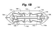
- FIG. 1Bis a side view of the distractible intervertebral body fusion device of FIG. 1A .
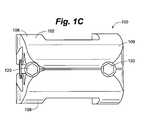
- FIG. 1Cis an end view of the distractible intervertebral body fusion device of FIG. 1A .
- FIG. 2Ais a perspective view of an embodiment of a distractible intervertebral body fusion device according to an aspect of the present invention.
- FIG. 2Bis a side view of the distractible intervertebral body fusion device of FIG. 2A .
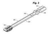
- FIG. 3is a perspective view of an embodiment of a distractible intervertebral body fusion device and an insertion tool according to an aspect of the present invention.
- FIG. 4is a side view of an embodiment of a distractible intervertebral body fusion device being inserted into a disc space according to an aspect of the present invention.
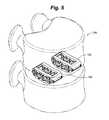
- FIG. 5is a perspective view of a pair of distractible intervertebral body fusion devices inserted into a disc space according to an aspect of the present invention.
- FIG. 6is a side view of an embodiment of a distractible intervertebral body fusion device according to an aspect of the present invention.
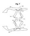
- FIG. 7is a side view of an embodiment of a distractible intervertebral body fusion device according to an aspect of the present invention.
- FIG. 8Ais a partial view of a portion of an embodiment of a distractible intervertebral body fusion device according to an aspect of the present invention.
- FIG. 8Bis a partial view of a portion of an embodiment of a distractible intervertebral body fusion device according to an aspect of the present invention.
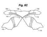
- FIG. 8Cis a partial view of a portion of an embodiment of a distractible intervertebral body fusion device according to an aspect of the present invention.
- FIG. 8Dis a partial view of a portion of an embodiment of a distractible intervertebral body fusion device according to an aspect of the present invention.
- FIG. 8Eis a partial view of a portion of an embodiment of a distractible intervertebral body fusion device according to an aspect of the present invention.
- FIG. 8Fis a partial view of a portion of an embodiment of a distractible intervertebral body fusion device according to an aspect of the present invention.
- FIG. 8Gis a partial view of a portion of an embodiment of a distractible intervertebral body fusion device according to an aspect of the present invention.
- FIG. 9is a side view of an embodiment of a distractible intervertebral body fusion device according to an aspect of the present invention.
- FIG. 10is a perspective view of the distractible intervertebral body fusion device of FIG. 9 .
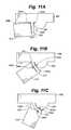
- FIG. 11Ais a partial view of a portion of an embodiment of a distractible intervertebral body fusion device according to an aspect of the present invention.
- FIG. 11Bis a partial view of a portion of an embodiment of a distractible intervertebral body fusion device according to an aspect of the present invention.
- FIG. 11Cis a partial view of a portion of an embodiment of a distractible intervertebral body fusion device according to an aspect of the present invention.
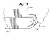
- FIG. 12is a partial view of a portion of an embodiment of a distractible intervertebral body fusion device according to an aspect of the present invention.
- FIG. 13Ais a partial view of a portion of an embodiment of a distractible intervertebral body fusion device according to an aspect of the present invention.
- FIG. 13Bis a partial view of a portion of an embodiment of a distractible intervertebral body fusion device according to an aspect of the present invention.
- FIG. 13Cis a partial view of a portion of an embodiment of a distractible intervertebral body fusion device according to an aspect of the present invention.
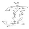
- FIG. 14is a side view of an embodiment of a distractible intervertebral body fusion device according to an aspect of the present invention.
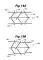
- FIG. 15Ais a simplified side view of an embodiment of a distractible intervertebral body fusion device according to an aspect of the present invention.
- FIG. 15Bis a simplified side view of an embodiment of a distractible intervertebral body fusion device according to an aspect of the present invention.
- FIG. 16is a side view of a circular flexure.
- FIG. 17is a side view of an elliptical flexure.
- FIG. 18is a side view of a leaf flexure.
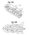
- FIG. 19Ais a perspective view of a distractible intervertebral body fusion device according to an aspect of the present invention.
- FIG. 19Bis a side view of the distractible intervertebral body fusion device of FIG. 19A .
- FIG. 20Ais a perspective view of a distractible intervertebral body fusion device according to an aspect of the present invention.
- FIG. 20Bis a side view of the distractible intervertebral body fusion device of FIG. 20A .
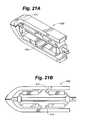
- FIG. 21Ais a perspective view of a distractible intervertebral body fusion device according to an aspect of the present invention.
- FIG. 21Bis a side view of the distractible intervertebral body fusion device of FIG. 21A .
- FIG. 22Ais a perspetive view of a distractible intervertebral body fusion device according to an aspect of the present invention.
- FIG. 22Bis a side view of the distractible intervertebral body fusion device of FIG. 22A .
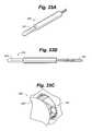
- FIG. 23Ais a perspective view of a distractible intervertebral body fusion device according to an aspect of the present invention.
- FIG. 23Bis a side view of the distractible intervertebral body fusion device of FIG. 23A .
- FIG. 24is an end view of a distractible intervertebral body fusion device according to an aspect of the present invention.
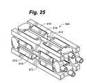
- FIG. 25is a perspective view of a distractible intervertebral body fusion device according to an aspect of the present invention.
- FIG. 26Ais a perspective view of a distractible intervertebral body fusion device according to an aspect of the present invention.
- FIG. 26Bis a side view of the distractible intervertebral body fusion device of FIG. 26A .
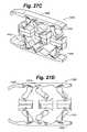
- FIG. 27Ais a perspective view of a distractible intervertebral body fusion device according to an aspect of the present invention.
- FIG. 27Bis a side view of the distractible intervertebral body fusion device of FIG. 27A .
- FIG. 27Cis a simplified side view of the distractible intervertebral body fusion device of FIG. 27A .
- FIG. 27Dis a simplified side view of the distractible intervertebral body fusion device of FIG. 27A .
- FIG. 28Ais a perspective view of a distractible intervertebral body fusion device according to an aspect of the present invention.
- FIG. 28Bis a side view of the distractible intervertebral body fusion device of FIG. 28A .
- FIG. 29Ais a perspective view of a distractible intervertebral body fusion device according to an aspect of the present invention.
- FIG. 29Bis a side view of the distractible intervertebral body fusion device of FIG. 29A .
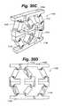
- FIG. 30Ais a perspective view of a distractible intervertebral body fusion device according to an aspect of the present invention.
- FIG. 30Bis a side view of the distractible intervertebral body fusion device of FIG. 30A .
- FIG. 30Cis a simplified side view of the distractible intervertebral body fusion device of FIG. 30A .
- FIG. 30Dis a simplified side view of the distractible intervertebral body fusion device of FIG. 30A .
- FIG. 31Ais a perspective view of a distractible intervertebral body fusion device according to an aspect of the present invention.
- FIG. 31Bis an end view of the distractible intervertebral body fusion device of FIG. 31A .
- FIG. 31Cis a side view of the distractible intervertebral body fusion device of FIG. 31A .
- FIG. 32Ais a perspective view of a distractible intervertebral body fusion device according to an aspect of the present invention.
- FIG. 32Bis an end view of the distractible intervertebral body fusion device of FIG. 32A .
- FIG. 33Ais a partial perspective view of an embodiment of an insertion tool according to an aspect of the present invention.
- FIG. 33Bis a partial top view of the insertion tool of FIG. 33A and a distractible intervertebral body fusion device according to an aspect of the present invention.
- FIG. 33Cis a partial perspective view of the insertion tool of FIG. 33A .
- Device 100includes a device body 102 .
- Device body 102can include a nose portion 104 , a rear portion 106 , a pair of opposed end plates 108 , structural members 110 and flexure members 112 attaching one end of the structural members 110 to end plates 108 and the other end of structural members 110 to blocks 114 a , 114 b.
- Device body 102can include two sets of structural members 110 , or struts, on each side ( FIGS. 1A-1D ) or can include three, or more, sets of structural members 110 on each side ( FIGS. 2A-2B ). As will be discussed in more detail herein, addition of a third strut provides greater stability to the device 100 .
- Flexure members 112are thin strips of material that connect the structural members to the end plates 108 and expansion blocks 114 . The flexure members 112 allow a one-piece device 100 to behave similarly to a device having multiple parts and a rotating pin joint. Flexure members 112 can, for example, be band flexures ( FIGS. 1A-1C and 2 A- 2 B), circular flexures ( FIG. 16 ), elliptical flexures (FIGS. 17 and 20 A-B), or leaf flexures ( FIGS. 18 , 19 A-B, 21 A-B and 22 A-B).
- each end plate 108includes a rectangular opening 116 . Opening can be used to facilitate bone growth through the device 100 .
- opening 116can be filled with a gel, rubber, or other complaint material that can replicate the nucleus of an interverterbral disc and supplement the strength of the flexures 112 in compressive, shear, and torsional loading conditions.
- a generally solid surface or a surface with multiple openingscan be provided on each end plate 108 .
- End plates 108can have a rough surface or teeth to create friction with the end plates of the vertebra to prevent accidental extrusion of the device 100 .
- the device body 102can be overmolded with a polymer or other material to supplement the strength of the device.
- a polymer or other materialfor example, long carbon nanotube chains can be applied to the surface of the device so that as the device distracts the carbon nanotubes align along the surface of the flexures to add to the stability of the device.
- Nose portion 104can be tapered to facilitate the insertion of the device 100 into the disc space.
- Rear portion 106can also be tapered.
- nose portion 104 and rear portion 106can be left open to accommodate a tapered delivery shaft that can extend all the way through the device 100 .
- Drive screws 118can be inserted through guide apertures 120 in rear portion 106 and through expansion blocks 114 . Actuation of drive screws 118 drives blocks 114 closer together, which causes deflection of the flexure members 112 , resulting in expansion of the structural members 110 and distraction of the end plates 108 .
- blocks 114 b in FIGS. 1A-1Ccan be tapped to accommodate drive screws 118 and blocks 114 a can provide a clearance fit with screws 118 . When drive screws 118 are actuated, this allows blocks 114 a to be pulled towards blocks 114 b , causing the device 100 to distract. Similarly, blocks 114 a and 114 c in FIGS.
- mechanisms other than drive screwscan be used to distract device.
- Such mechanismsinclude, for example, a pop-rivet mechanism, a sardine key and ribbon, a tourniquet and wire, a saw blade/ratchet, and shape changing materials such as a shape memory alloy or a conducting polymer actuator.
- a zip-tie-like drive mechanism 819can be used to distract end plates 808 of device 800 .
- the rear block 814can include a projection 821 for engaging the teeth 823 of the drive mechanism 819 .
- piezo-electric inch-worm motorscan be used to actuate the movement of blocks 114 .
- a ballooncan be inserted into device and inflated to expand the device. The balloon can remain in the device and function like the nucleus of a disc.
- device body 102is shaped to be ergonomic.
- Device body 102can have various shapes, such as, for example, rectangular, kidney, or football shaped.
- a kidney or football shaped device body 102maximizes contact between the device and the vertebral bodies because the end plates of vertebrae tend to be slightly concave.
- One or both ends of the devicemay also be tapered in order to facilitate insertion. This minimizes the amount of force needed to initially insert the device and separate the vertebral bodies.
- the devicemay be convex along both its length and its width, or bi-convex.
- Device 100can be constructed in various sizes depending on the type of vertebra and size of patient with which it is being used.
- Device body 102can also be comprised of various materials.
- deviceis comprised of a ductile material.
- materialscan include, for example, titanium, nitinol, and thermoplastics.
- the material near the ends of the flexures 112can be cold-worked to increase the stiffness of the device as it distracts. Heat treating could also be used to alleviate machining stresses and could be followed by hardening treatment to make the device stiffer.
- the flexurescan be affixed to the device in subsequent manufacturing steps in order to permit the flexures to be made from a different material or materials, or materials treated differently, than the structural members and end plates of the device.
- Flexurescould also be laminated beams having a core of another stiff material, a soft material such as a foam, or an open core. Having a soft or open core would allow the flexures to effectively decrease in thickness as they are bent around the curved surfaces of the struts. This would decrease the amount of strain present in the flexure due to bending, allowing the device to accommodate greater functional loading.
- Device 100can be placed between adjacent vertebra or vertebral bodies and used both to distract the endplates of the adjacent vertebral bodies and serve as a fusion device.
- An insertion tool 200can be used to insert a device between vertebral bodies 124 as shown in FIGS. 3-5 .
- insertion tool 200can include a pair of parallel screwdrivers or wrenches 202 temporarily affixed to the drive screws 118 with retainers 204 .
- insertion tool 200extends rearwardly from device 100 . In another embodiment, insertion tool 200 may also extend distally from device 100 .
- device 100can include an open nose portion 104 and rear portion 106 to allow it to be threaded onto insertion tool 200 and insertion tool 200 can also be used to initially distract the vertebral bodies.
- the insertion tool 200can include a single handle 201 and a gear system 203 where the handle 201 has an internal gear that, when turned, turns external gears on the shafts that turn the screws on the device 100 as depicted in FIGS. 33A-C .
- Device 100can be inserted with tapered nose portion 104 first. In one embodiment, a working channel of 8-26 mm is required for insertion of the device.
- One device 100can be inserted, or, for additional support, two devices 100 can be inserted as shown in FIG. 5 . Two devices 100 can be especially useful for treating larger patients in which the device may encounter higher loads.
- three or more small devicescan be inserted into the disc space in order to very accurately control the orientation and distance between discs. Three or more distraction mechanisms may be positioned circumferentially between two circular endplates to result in very accurate control and orientation of the end plates. Such a device would resemble a hexapod.
- two or more devicesmay be mated or assembled in the disc space to work congruently in performing distraction either in height or width.
- insertion tool 200can be actuated to rotate drive screws 118 .
- Drive screws 118can be actuated from the rear of device 106 to allow insertion tool to reposition or, if necessary, remove device 100 prior to disengaging from device 100 .
- Drive screws 118can be actuated the same amount for uniform distraction on both sides of an embodiment with two drive screws or may be actuated different amounts for non-uniform distraction with one side of the device 100 higher than the other.
- Non-uniform distractioncauses torsional forces on flexures.
- FIG. 24depicts a device 100 have non-uniform distraction.
- an embodimentcan be driven with a single flexure and single drive screw or with multiple flexures multiplexed to a single drive screw arrangement.
- device 100can easily be distracted from its lowest, or most compressed, state. This is because the flexure members 112 on each end of a given structural member are oriented such that the tensile loads on the flexures do not act towards each other, but instead pass by each other, like passing cars (see arrow A and arrow B in FIG. 1B ).
- Common jacks, which do not utilize flexure members,may have difficulty distracting from the lowest state because the tensile loads can act “heads on” with each other, putting the device under strong internal horizontal compression but without a significant force component in the vertical direction at the lowest state that can easily initiate distraction.
- the tension in the flexure member required to support a compressive loadis equal to the compressive load multiplied by the cosine of the angle of the rigid link divided by the sine of the rigid link. Because the sine of zero degrees, the angular position of normal scissor jacks in the compressed state, is equal to zero, the force required for initial distraction can be effectively very large.
- the rigid links of the device of various embodiments of the present inventionmay start off in the position of zero angular position, but because the flexure members are on opposing sides of the rigid links the effective angular position is non-zero, making the force required for initial distraction finite and generally smaller than a conventional scissor jack.
- FIGS. 8A-8Ddepict a flexure member 112 and structural member 110 before distraction, whereas FIGS. 8B and 8C depict after distraction.
- Each flexure member 112begins wrapped around the curved end of the structural member 110 . Note in FIG. 8A that the flexure 112 rests on the structural member 110 .
- FIGS. 8E-8Gdepict the behavior of flexures as the device is distracted.
- Flexure member 112defines a first open area, or kerf 140 a , between curved backstop 122 and flexure member 112 and a second kerf 140 b between inner perimeter 142 of structural member 110 and flexure member 112 .
- kerf 140 ais wider than kerf 140 b .
- flexure member 112flattens out towards curved backstop 122 , so kerf 140 b widens as kerf 140 a narrows.
- the fulcrum around which flexure member 112 bendsis shown by arrows 144 a and 144 b .
- the fulcrum 144 a , 144 btranslates along the flexure member 112 as it bends. Fulcrum 144 a , 144 b therefore travels in both vertical and horizontal directions. This provides for increased distraction of the device.
- the fulcrum 144 a , 144 bmoves along the flexure member 112 as the device distracts, a greater portion of the compressive load on the device 100 is supported by the structural member 110 and, accordingly, the tensile forces on the flexure member 112 are reduced.
- the device 100 of this embodimentis therefore strongest when it is fully distracted.
- Device 300includes a device body 302 having a nose portion 304 , a rear portion 306 , a pair of opposed end plates 308 , structural members 310 , flexure members 312 , and drive blocks 314 .
- nose portion 304 and rear portion 306can be open.
- nose 304 and rear 306 portionscan be used to accommodate an insertion tool for delivery of device 300 .
- drive blocks 314 and end plates 308provide outwardly curved backstops 322 for flexure members 312 (in contrast to the inwardly curved backstops 122 depicted in the previous Figures).
- Flexures 312curve around backstops 322 as the device 300 distracts as depicted in FIGS. 11A-11C .
- flexure member 312In the collapsed state shown in FIG. 11A , flexure member 312 is parallel to an inner surface 342 of structural member 310 . As the device 300 distracts, flexure member 312 bends around backstop 322 , widening kerf 340 b and narrowing kerf 340 a .
- Fulcrum 344 a , 344 bthe fulcrum translates along the length of flexure member 312 (in both the horizontal and vertical directions) as the device distracts. Fulcrum 344 a , 344 b is always perpendicular to inner surface 342 of structural member 310 . This results in the entire load on the device 300 being carried in compression by structural members 310 . Therefore, there is little or no tensile force on flexure members 312 . This allows flexure members 312 to be of a thickness or a material such that they enjoy an essentially infinite fatigue life.
- FIG. 12depicts a further flexure embodiment employing this principal.
- the flexure 312 in FIG. 12is cut an additional length into end plate 308 . This can help reduce the stress in the device and may improve fatigue life.
- the thickness of the flexure 312 in relation to the bend radius of the curved backstop 322determines the fatigue life of the flexure.
- flexurescan be configured and designed to have very long fatigue life.
- a device made from nitinol having a thickness of the flexure members 312 that is preferably between 8% and 10% of the bend radius of the backstop 322 , with a maximum thickness of 18%has an infinite fatigue life.
- a flexure made from PEEKpreferably has a thickness that is 4.5% to 6.4% of the bend radius, with a maximum thickness of 15%.
- a flexure comprised of annealed titaniumcan have a thickness of up to 18% of the bend radius.
- flexurescan be configured and designed to have a finite fatigue life associated with a predetermined range of maximum number of cycles of expansion and contraction.
- FIGS. 13A-13Cdepict a partial view of a distractible intervertebral body fusion device 400 including a further flexure embodiment.
- Backstop 422 on end plate 408is flat.
- Flexure 412begins curved around inner surface 442 of structural member 410 and flattens out, thereby widening kerf 440 b and narrowing kerf 440 a , as the device distracts.
- Fulcrum 444 a , 444 bagain translates along flexure member 412 as the device distracts, providing increased distraction.
- structural member 410supports more of the load on device 400 in compression and less is supported by the flexure member 412 in tension.
- a bone growth stimulantsuch as autograft, bone morphogenic protein, or bone enhancing material
- bone growth stimulantis delivered through a hollow chamber in insertion tool before insertion tool is disengaged from device.
- the devicesupports in-vivo loads during the time fusion occurs between the vertebral bodies and can support axial loads up to four times the weight of the patient.
- openings in end platesallow for bone growth through the device.
- some embodiments of the devicecan be distracted in only one direction, such as vertically. In other embodiments, the device can be distracted in two directions, such as both vertically and horizontally. In one embodiment depicted in FIG. 25 , the device 600 can be distracted in both the vertical and horizontal directions.
- Device 600includes a plurality of structural members 610 and flexures 612 on all four sides of the device 600 . Separate drive screws 618 can be used to control horizontal and vertical distraction. In one embodiment, all drive screws can be controlled by a single drive member. This would provide for simultaneous horizontal and vertical distraction. In another embodiment as shown, each drive screw can be individually controlled in order to allow horizontal and vertical distraction to be performed independently.
- This devicecan be inserted through very small openings, which can then be made wider before being distracted taller. It is in this configuration that the device retains its compressive strength during and after vertical compression while being able to be distracted in the horizontal direction.
- the screws that actuate horizontal expansionmay be timed and driven together and the screws that actuate vertical expansion may be timed and driven together.
- a third strutmay provide greater stability to certain embodiments of the device over a two-strut design.
- excessive and/or uneven forces on a two-strut designcan sometimes cause the device 100 to sublux as shown in FIG. 14 .
- Subluxationcauses the end plates 108 , structural members 110 and, if during implantation, the drive screws 118 , to become misaligned. This can cause collapse of the disc space and risks deformity.
- a third set of structural membersmay be added to provide stability to help support excessive and/or uneven loads and prevent subluxation.
- a third strutallows a physician, in some embodiments, the flexibility to control the parallelism of the end plates. As seen in FIG.
- the third strut 134can be positioned apart from the first 132 and second 130 struts in order to maintain the end plates 108 completely parallel.
- a physicianmay desire to maintain the end plates 108 in a non-parallel position. As can be seen in FIG. 15B , this can be accomplished by positioning the third strut 134 nearer to or farther from the other struts 130 , 132 or by actuating the separate screw drives at separate rates. In this manner, a physician can configure the device 100 to maintain the end plates 108 in a non-parallel position to match the curvature of the spine.
- the non-parallel positioncan be configured while the device is being implanted by using a drive mechanism that has the flexibility to adjust the position of the third strut 134 with respect to the second strut 132 .
- the length of strut 134may be different from that of strut 132 resulting in the end plates 108 being parallel during implantation but growing increasingly less parallel as the device is distracted.
- FIGS. 19A-19Bdepict a distractible intervertebral body fusion device 500 utilizing leaf flexures 512 .
- This deviceincludes small fillets 513 where the flexures 512 connect with the structural members 510 . In this embodiment, no portion of the flexures 512 rests on the device body, so the entirety of any load on the device will be carried by the flexures.
- FIGS. 21A-21B and 22 A- 22 Balso depict devices 500 utilizing leaf flexures 512 . In these embodiments, there are no fillets at the connection between the flexures 512 and the structural members 510 .
- FIGS. 20A-20Bdepict a distractible intervertebral body fusion device 700 that utilizes elliptical flexures 712 .
- FIGS. 27A-27Ddepict another embodiment of a distractible intervertebral body fusion device 1000 according to an aspect of the present invention.
- Device 1000includes three sets of structural members 1010 on each side of the device 1000 and utilizes flexures 1012 similar to those depicted in FIGS. 8A-8G .
- the use of three sets of strutsprovides greater strength and helps avoid buckling or collapse of the device 1000 .
- FIGS. 27C and 27Ddepicted a simplified view of the distracted device 1000 under a compressive load.
- the flexures 1012 in the middle of the device 1000deform differently than the ones on each end due to the asymmetry of the device.
- the end plates 1008 of this embodimentare depicted as bending slightly under the compressive load. This is because the thickness of the end plates can be selected such that they are able to bend in-vivo to evenly distribute the supportive load of the device over the endplates of the vertebral bodies.
- FIGS. 28A and 28Bdepict a variation of the device 1000 of FIGS. 27A-27D having a differential screw drive 1018 .
- the wedges 1025provide a greater level of compressive strength to the device 100 once it is distracted than the flexures 1012 do alone.
- the wedges 1025also reduce the potential for the device to sublux.
- the wedges 1025may be shaped or sized such that the device is primarily supported by the flexures and has the ability to sublux slightly but not fully.
- FIGS. 30A-30DAnother embodiment of a distractible intervertebral body fusion device 1100 according to an aspect of the present invention is depicted in FIGS. 30A-30D .
- This embodimentuses flexures 1112 similar to those shown in FIGS. 11A-11C .
- the middle flexures 1112 of device 1100deform differently than the ones on each end due to the asymmetric sets of structural members 1110 .
- the end plates 1108are thicker and do not deform under the compressive load.
- FIGS. 31A-31CAnother embodiment of a distractible intervertebral body fusion device 1200 according to an aspect of the present invention is depicted in FIGS. 31A-31C .
- the device 1200includes two sets of structural members 1210 and flexures 1212 on each side of the device 1200 .
- the device 1200includes four distractible pins 1207 extending between the end plates 1208 that resist torsional forces on the device 1200 .
- the pins 1207also limit the device to movement in the vertical direction and eliminate the possibility of subluxation.
- a pair of drive screws 1218can be used to distract the devices.
- FIGS. 32A and 32Bdepict a variation of the device 1200 that utilizes a single drive screw 1218 .
- 32A and 32Balso depict an embodiment where the blocks 1214 and the backstops 1222 that create the “frowning eyebrows” have been added as separate parts in order to dramatically thin the kerf that is present in earlier embodiments.
- the thinning of the kerfwill reduce local stresses and strains in the flexures and increase the fatigue life.
- distractible intervertebral body fusion devicehas a one-piece device body that can be manufactured in a distracted or partially distracted state. This provides great cost savings over devices that require multiple pieces to be separately manufactured and assembled. Manufacturing in the distracted state provides additional clearance for assembly and for access by manufacturing tools, the size of which is inversely proportional to the cost of manufacturing.
- the devicewhen the device is manufactured in the distracted state, the device can be compressed into a position of minimal height while compressive stress remains in the flexure members. This compressive stress results in a negative mean stress, which can extend the fatigue life of the device.
- the devicecan be manufactured using wire or sink edm.
- the devicecan be manufactured using three-dimensional printing techniques or the like.
- portions of the flexurescan be machined separately and welded to the device. This allows for flexures that have zero kerf and rest completely against the backstops once distracted.
- the surface of the devicecan be treated to minimize surface roughness or to reduce pitting of the material within the body.
- a rough surface or pitscan increase the stress on the device, which can result in shortening of the fatigue life and/or reduce fatigue strength.
- the surfacecan be treated with electro-polishing.
- the surfacecan be left untreated because a rough surface on the end plates helps prevent accidental extrusion of the device.
- the devicecan also be coated with a highly elastic, impermeable material to extend its fatigue life. Specifically, the impermeable material would prevent the corrosive properties of blood from degrading the device.
- the devicecan be comprised of a biocompatible material, so that no coating is necessary.
- the devicecan be made of a biodegradable material designed to degrade in the body at a selected stage of the healing process, such as after bone fusion.
- Supportscan be used to supplement the compressive strength, bending, or torsional strength of device.
- one or more rigid supportscan be inserted into the open space between end plates after distraction to help keep the end plates in their distracted state.
- chockscan be placed at the intersection of structural members in each strut to provide further support for struts.
- a rod and screwscan be used with the device as part of an assembly affixed to the vertebral body.
- distractible intervertebral body fusion device 900can comprise a rigid cage capable of tilting front to back and/or side to side. Flexures 912 and/or springs can be oriented around the periphery of the device to allow for tilting in a variety of axes. A device capable of tilting can be beneficial in that providing additional degrees of flexibility built into the device can promote bone growth, distribute stress across the surface of the end plates, and allow the device to adjust to the curvature of an individual's spine.
- the strutscomprising structural members, flexures, and blocks can be replaced with large flexures extending between the end plates.
- Such a devicecan be non-distractible and can be provided in different sizes for insertion into variously sized disc spaces.
- a device in accordance with the various embodimentscan be used for a variety of intervertebral fusion applications, including, for example, cervical, thoracic anterior lumbar, trans-foraminal lumbar, extreme lateral lumbar, and posterior lumbar.
- devicecan be inserted at 6 mm height and distracted to 14 mm for cervical applications and can be inserted at 7 mm and distract to 16 mm for other applications.
- Prototypes of this devicehave successfully demonstrated distraction to 220% of the original height.
- Scissorjacks of the prior art designed for distraction of vertebral bodiesare capable of distracting to only less than 200% of the original height.
- CervicalThe device is implanted via an anterior approach at the C3 to C7 levels using autograft.
- the deviceis used with supplemental anterior plate fixation.
- Trans-foraminal lumbarThe device is implanted via a posterior approach from the L2 to S1 levels using autograft. The device is used with supplemental posterior rod fixation.
- Posterior lumbarThe device is implanted via a posterior approach from the L2 to S1 levels using autograft. Two devices are implanted; one on the left side of the disc space and the other on the right side of the disc space. The device is used with supplemental posterior rod fixation.
- Anterior lumbarThe device is implanted via an anterior approach from the L3 to S1 levels using autograft. The device is used with supplemental anterior plating fixation of posterior rod fixation.
- Extreme lateral lumbarThe device is implanted via a lateral approach from the T12 to L4 levels using autograft. The device is used with supplemental posterior rod fixation.
- the devicecan be used in vertebral body replacement. After resection of a vertebral body or multiple vertebrae due to fracture or tumor, the device can be distracted to bridge two separate vertebrae. The distracted device bridges and supports the void left after resection.
- the devicecan be constructed in different sizes to accommodate the size difference of cervical, thoracic and lumbar vertebrae.
- the devicecan be used as an interspinous distraction device.
- the devicecan be placed between two adjacent spinous processes through a minimal access system.
- the devicecan be inserted in a collapsed configuration to allow ease of placement. Once in position, the device can be actuated to lock the vertebrae in a distracted position.
- the devicecan have gripping teeth at the point of contact with the spinous processes to help fix it in place.
- devicein another embodiment, can be used for interspinous fusion.
- the devicecan be placed between two adjacent spinous processes through a minimal access system in a collapsed configuration. Once in position, the device can be actuated to lock the vertebra in a distracted position.
- the devicecan have a bolt locking mechanism to lock the device in the distracted position and to lock the locking plates through the spinous processes.
- the devicecan also have gripping teeth on the outside to help keep it in place.
- Autograft or bone fusion enhancing materialcan be placed in the open space in device.
- devicecan be used for intervertebral disc replacement.
- the devicecan be placed in a disc space after removal of the nucleus pulposus.
- the devicecan then be distracted to the proper disc space height for the type of vertebra—cervical, thoracic, or lumbar.
- the devicethen functions as a mechanical annulus fibrosis.
- the devicecan be used on its own or in combination with a nucleus pulposus implant or soft posterior rodding system.
- a PEEK or biogel nucleus pulposus implantcan be placed into the open area in the device after it is distracted.
- the implant and devicewill function as a mechanical disc device.
- the devicecan be constructed of a flexible material having similar properties to that of a human disc.
- the devicecan be used as a distractible cage for osteoporotic bone.
- the devicecan be constructed of a material with a modulus similar to that of bone and can be coated with a hydroxyappetite to enhance bone formation in the patient.
- the devicecan be used in flexure member facet joint replacement. After resection of a hypertrophic facet joint, the device can be actuated and subluxed. Each subluxed plate can be fixed to adjacent vertebrae with a pedicle screw. This will allow motion similar to that of a facet joint and prevent instability.
- the devicecan be part of a soft fusion device system and can be used in combination with an intervertebral disc replacement device.
- the devicecan be used as a programmable distraction cage with a dynameter and bone stimulator.
- a programmable micro-machine actuator devicecan be implanted within the device. The device is distracted during implantation and can provide force readings through a radio frequency communicator post-surgery. The shape of the device can be altered while it is implanted by distracting the end plates with the actuator device, which can result in lordosis, kyphosis, further distraction, or less distraction.
- a battery devicepowers the system and can also form a magnetic field that works as a bone stimulator. The battery life may be limited to a short period of time, such as one week.
- Small movements of the devicecan be used to generate electrical energy with piezo-electrics or conducting polymers that may be used to recharge the batteries, capacitors, or other such power storage devices.
- the devicemay be powered through an RF inductive or capacitatively coupled arrangement.
- the devicecan be a self-actuating distractible cage.
- the devicecan be inserted into the disc space in a collapsed state. Once the device is released, it can slowly distract to a preset height.
- the distractionmay be driven by spring action of the flexures.
- the devicecan be used in facial maxillary surgery as a fracture lengthening device for mandibular fractures.
- the devicecan be designed with narrow end plates having perpendicular plates with holes that allow fixation of each plate to either a proximal or distal fracture.
- the devicecan be actuated through a slow spring action flexure mechanism to a preset height. This will allow lengthening of the defect in cases of fracture bone loss, dysplasia, or hypoplasia.
- devicein orthopedic applications as a lengthening nail for distraction of long bone fractures. After an orthopedic fracture occurs with bone loss, a distractible elongating nail can be placed to lengthen the bone. The elongation occurs over a few days with micrometer movements. This application will involve a distraction device inserted in between the moving portion of the nails exerting counter-distraction forces, which will provide lengthening of the bone.
- devicein another embodiment, can be used in a gastric band application.
- gastric bandshave an inner tube rubber diaphragm that is constricted via tubing attached to a small reservoir placed superficially under the skin in an accessible area.
- the constriction mechanismrequires an injection of saline into the reservoir by a surgeon a few times a year.
- a flexure embodimentwill include an elliptical device having two flexure members that constrict the center by opposing distraction forces.
- the devicewill be open on one end to allow placement around the upper portion of the stomach.
- the devicecan include a programmable micro-machine to actuate the flexure members.
- the devicecan also measure stomach fundus pressures and diurnal variations in the size of the stomach.
- the flexure devicecan be used to replace phalangeal joints in the hand, metatarsal joints in the foot, or calcaneal-talus joints. These joints can have flexural members implants that will allow motion of adjacent bones and limit hyper-extension or hyper-flexion.
- the devicecan be used to create prosthetic limbs.
- the flexural membercan lengthen to adjust for a growing limb or to make slight adjustment in order to match the size of a homologous limb.
Landscapes
- Health & Medical Sciences (AREA)
- Engineering & Computer Science (AREA)
- Biomedical Technology (AREA)
- Orthopedic Medicine & Surgery (AREA)
- Neurology (AREA)
- General Engineering & Computer Science (AREA)
- Transplantation (AREA)
- Oral & Maxillofacial Surgery (AREA)
- Animal Behavior & Ethology (AREA)
- Cardiology (AREA)
- Veterinary Medicine (AREA)
- Heart & Thoracic Surgery (AREA)
- Vascular Medicine (AREA)
- Life Sciences & Earth Sciences (AREA)
- Public Health (AREA)
- General Health & Medical Sciences (AREA)
- Mechanical Engineering (AREA)
- Physical Education & Sports Medicine (AREA)
- Supporting Of Heads In Record-Carrier Devices (AREA)
- Prostheses (AREA)
- Pivots And Pivotal Connections (AREA)
- Springs (AREA)
Abstract
Description
Claims (17)
Priority Applications (4)
| Application Number | Priority Date | Filing Date | Title |
|---|---|---|---|
| US12/650,994US8523944B2 (en) | 2008-12-31 | 2009-12-31 | Methods and apparatus for vertebral body distraction and fusion employing flexure members |
| US13/189,410US8636746B2 (en) | 2009-12-31 | 2011-07-22 | Methods and apparatus for insertion of vertebral body distraction and fusion devices |
| US13/891,356US8906100B2 (en) | 2008-12-31 | 2013-05-10 | Methods and apparatus for vertebral body distraction and fusion employing flexure members |
| US14/563,660US9445917B2 (en) | 2008-12-31 | 2014-12-08 | Methods and apparatus for expandable medical device employing flexure members |
Applications Claiming Priority (4)
| Application Number | Priority Date | Filing Date | Title |
|---|---|---|---|
| US14210408P | 2008-12-31 | 2008-12-31 | |
| US29120309P | 2009-12-30 | 2009-12-30 | |
| PCT/US2009/069876WO2010078468A2 (en) | 2008-12-31 | 2009-12-30 | Methods and apparatus for vertebral body distraction and fusion employing flexure members |
| US12/650,994US8523944B2 (en) | 2008-12-31 | 2009-12-31 | Methods and apparatus for vertebral body distraction and fusion employing flexure members |
Related Parent Applications (1)
| Application Number | Title | Priority Date | Filing Date |
|---|---|---|---|
| US12/841,465Continuation-In-PartUS8303663B2 (en) | 2009-07-22 | 2010-07-22 | Methods and apparatuses for vertebral body distraction and fusion employing a coaxial screw gear sleeve mechanism |
Related Child Applications (2)
| Application Number | Title | Priority Date | Filing Date |
|---|---|---|---|
| US13/189,410Continuation-In-PartUS8636746B2 (en) | 2009-12-31 | 2011-07-22 | Methods and apparatus for insertion of vertebral body distraction and fusion devices |
| US13/891,356ContinuationUS8906100B2 (en) | 2008-12-31 | 2013-05-10 | Methods and apparatus for vertebral body distraction and fusion employing flexure members |
Publications (2)
| Publication Number | Publication Date |
|---|---|
| US20100185291A1 US20100185291A1 (en) | 2010-07-22 |
| US8523944B2true US8523944B2 (en) | 2013-09-03 |
Family
ID=42310628
Family Applications (6)
| Application Number | Title | Priority Date | Filing Date |
|---|---|---|---|
| US12/650,994Expired - Fee RelatedUS8523944B2 (en) | 2008-12-31 | 2009-12-31 | Methods and apparatus for vertebral body distraction and fusion employing flexure members |
| US12/651,266Active2030-06-28US8540452B2 (en) | 2008-12-31 | 2009-12-31 | Flexible joint arrangement incorporating flexure members |
| US13/891,356ActiveUS8906100B2 (en) | 2008-12-31 | 2013-05-10 | Methods and apparatus for vertebral body distraction and fusion employing flexure members |
| US14/024,764Active2031-02-20US9381092B2 (en) | 2008-12-31 | 2013-09-12 | Flexible joint arrangement incorporating flexure members |
| US14/563,660ActiveUS9445917B2 (en) | 2008-12-31 | 2014-12-08 | Methods and apparatus for expandable medical device employing flexure members |
| US15/198,557Active2030-02-23US10060469B2 (en) | 2008-12-31 | 2016-06-30 | Flexible joint arrangement incorporating flexure members |
Family Applications After (5)
| Application Number | Title | Priority Date | Filing Date |
|---|---|---|---|
| US12/651,266Active2030-06-28US8540452B2 (en) | 2008-12-31 | 2009-12-31 | Flexible joint arrangement incorporating flexure members |
| US13/891,356ActiveUS8906100B2 (en) | 2008-12-31 | 2013-05-10 | Methods and apparatus for vertebral body distraction and fusion employing flexure members |
| US14/024,764Active2031-02-20US9381092B2 (en) | 2008-12-31 | 2013-09-12 | Flexible joint arrangement incorporating flexure members |
| US14/563,660ActiveUS9445917B2 (en) | 2008-12-31 | 2014-12-08 | Methods and apparatus for expandable medical device employing flexure members |
| US15/198,557Active2030-02-23US10060469B2 (en) | 2008-12-31 | 2016-06-30 | Flexible joint arrangement incorporating flexure members |
Country Status (5)
| Country | Link |
|---|---|
| US (6) | US8523944B2 (en) |
| EP (1) | EP2376730A2 (en) |
| JP (1) | JP2012514703A (en) |
| CN (1) | CN102369332B (en) |
| WO (1) | WO2010078520A2 (en) |
Cited By (102)
| Publication number | Priority date | Publication date | Assignee | Title |
|---|---|---|---|---|
| US20130173000A1 (en)* | 2011-12-30 | 2013-07-04 | Metal Industries Research & Development Centre | Interbody Cage for Spine Fusion |
| US20130197642A1 (en)* | 2012-01-28 | 2013-08-01 | Mark J. Ernst | Expandable implant for mammalian bony segment stabilization |
| US8771360B2 (en) | 2009-07-22 | 2014-07-08 | Spinex Tec, Llc | Methods and apparatuses for vertebral body distraction and fusion employing a coaxial screw gear sleeve mechanism |
| US8906100B2 (en) | 2008-12-31 | 2014-12-09 | Ex Technology, Llc | Methods and apparatus for vertebral body distraction and fusion employing flexure members |
| US8932302B2 (en) | 2011-07-22 | 2015-01-13 | Spinex Tec, Llc | Methods and apparatus for insertion of vertebral body distraction and fusion devices |
| US8940049B1 (en)* | 2014-04-01 | 2015-01-27 | Ex Technology, Llc | Expandable intervertebral cage |
| US9005291B2 (en) | 2013-07-09 | 2015-04-14 | Nlt Spine Ltd. | Orthopedic implant with adjustable angle between tissue contact surfaces |
| US9198765B1 (en) | 2011-10-31 | 2015-12-01 | Nuvasive, Inc. | Expandable spinal fusion implants and related methods |
| US9216096B2 (en) | 2010-03-16 | 2015-12-22 | Pinnacle Spine Group, Llc | Intervertebral implants and related tools |
| US20160014914A1 (en)* | 2014-07-09 | 2016-01-14 | Christian Stroetmann | Flexible electronic device housing |
| US9283092B2 (en) | 2010-07-15 | 2016-03-15 | Nlt Spine Ltd. | Laterally deflectable implant |
| US20160145919A1 (en)* | 2014-11-26 | 2016-05-26 | Brigham Young University | Hinge system having combined compliant hinges |
| US9380932B1 (en) | 2011-11-02 | 2016-07-05 | Pinnacle Spine Group, Llc | Retractor devices for minimally invasive access to the spine |
| US9408712B2 (en) | 2010-07-15 | 2016-08-09 | NLT-Spine Ltd. | Surgical systems and methods for implanting deflectable implants |
| US9414936B2 (en) | 2011-12-19 | 2016-08-16 | Warsaw Orthopedic, Inc. | Expandable interbody implant and methods of use |
| US9445919B2 (en) | 2011-12-19 | 2016-09-20 | Warsaw Orthopedic, Inc. | Expandable interbody implant and methods of use |
| US9474561B2 (en) | 2013-11-19 | 2016-10-25 | Wright Medical Technology, Inc. | Two-wire technique for installing hammertoe implant |
| US9486328B2 (en) | 2014-04-01 | 2016-11-08 | Ex Technology, Llc | Expandable intervertebral cage |
| US20160324651A1 (en)* | 2013-05-10 | 2016-11-10 | Sidewinder Medical Products Llc | Expandable spinal fusion cage |
| US9498273B2 (en) | 2010-06-02 | 2016-11-22 | Wright Medical Technology, Inc. | Orthopedic implant kit |
| US9498266B2 (en) | 2014-02-12 | 2016-11-22 | Wright Medical Technology, Inc. | Intramedullary implant, system, and method for inserting an implant into a bone |
| US9504582B2 (en) | 2012-12-31 | 2016-11-29 | Wright Medical Technology, Inc. | Ball and socket implants for correction of hammer toes and claw toes |
| US9545274B2 (en)* | 2014-02-12 | 2017-01-17 | Wright Medical Technology, Inc. | Intramedullary implant, system, and method for inserting an implant into a bone |
| WO2017027277A1 (en)* | 2015-08-12 | 2017-02-16 | Warsaw Orthopedic, Inc. | Expandable spinal implant and method of implanting same |
| US9603643B2 (en) | 2010-06-02 | 2017-03-28 | Wright Medical Technology, Inc. | Hammer toe implant with expansion portion for retrograde approach |
| US9724139B2 (en) | 2013-10-01 | 2017-08-08 | Wright Medical Technology, Inc. | Hammer toe implant and method |
| US9724140B2 (en) | 2010-06-02 | 2017-08-08 | Wright Medical Technology, Inc. | Tapered, cylindrical cruciform hammer toe implant and method |
| US9730806B2 (en) | 2014-10-27 | 2017-08-15 | Warsaw Orthopedic, Inc. | Spinal implant system and method |
| US9737411B2 (en) | 2013-12-11 | 2017-08-22 | Nlt Spine Ltd. | Worm-gear actuated orthopedic implants and methods |
| US9808296B2 (en) | 2014-09-18 | 2017-11-07 | Wright Medical Technology, Inc. | Hammertoe implant and instrument |
| US9820865B2 (en) | 2013-10-31 | 2017-11-21 | Nlt Spine Ltd. | Adjustable implant |
| US9867717B2 (en) | 2009-03-19 | 2018-01-16 | Ex Technology, Llc | Stable device for intervertebral distraction and fusion |
| US20180049754A1 (en)* | 2015-03-13 | 2018-02-22 | Redemed S.R.L. | Intervertebral prosthesis, apparatus for implanting intervertebral prostheses and surgical method for implanting intervertebral prostheses, particularly for percutaneous mini-invasive surgery procedures |
| US9907670B2 (en) | 2015-01-21 | 2018-03-06 | Warsaw Orthopedic, Inc. | Unitarily formed expandable spinal implant and method of manufacturing and implanting same |
| US9937053B2 (en) | 2014-11-04 | 2018-04-10 | Warsaw Orthopedic, Inc. | Expandable interbody implant |
| US9937054B2 (en) | 2016-01-28 | 2018-04-10 | Warsaw Orthopedic, Inc. | Expandable implant and insertion tool |
| US9964142B2 (en)* | 2016-06-01 | 2018-05-08 | Wipotec Gmbh | Flexure hinge |
| US10012262B2 (en)* | 2016-06-01 | 2018-07-03 | Wipotec Gmbh | Flexure hinge |
| US10016284B2 (en) | 2005-04-12 | 2018-07-10 | Moskowitz Family Llc | Zero-profile expandable intervertebral spacer devices for distraction and spinal fusion and a universal tool for their placement and expansion |
| US10070970B2 (en) | 2013-03-14 | 2018-09-11 | Pinnacle Spine Group, Llc | Interbody implants and graft delivery systems |
| US10076423B2 (en) | 2016-01-04 | 2018-09-18 | Warsaw Orthopedic, Inc. | Pivoting wedge expanding spinal implant and method of implanting same |
| US10080597B2 (en) | 2014-12-19 | 2018-09-25 | Wright Medical Technology, Inc. | Intramedullary anchor for interphalangeal arthrodesis |
| US10137006B2 (en) | 2016-01-28 | 2018-11-27 | Warsaw Orthopedic, Inc. | Geared cam expandable interbody implant and method of implanting same |
| US10188526B2 (en) | 2015-10-26 | 2019-01-29 | Warsaw Orthopedic, Inc. | Spinal implant system and method |
| US10369012B2 (en)* | 2012-11-16 | 2019-08-06 | In Queue Innovations, Llc | Oblique expanding fusion cage device and method |
| US10492923B2 (en) | 2014-06-25 | 2019-12-03 | Seaspine, Inc. | Expanding implant with hinged arms |
| US10610376B2 (en) | 2015-10-16 | 2020-04-07 | Warsaw Orthopedic, Inc. | Expandable spinal implant system and method |
| US20200246164A1 (en)* | 2010-10-05 | 2020-08-06 | Eit Emerging Implant Technologies Gmbh | Minimally Invasive Intervertebral Systems And Methods |
| US10767032B2 (en)* | 2016-06-02 | 2020-09-08 | The Royal Institution For The Advancement Of Learning/Mcgill University | Bistable auxetics |
| US10779955B2 (en) | 2015-10-26 | 2020-09-22 | Warsaw Orthopedic, Inc. | Spinal implant system and method |
| US10973650B2 (en) | 2015-12-30 | 2021-04-13 | Nuvasive, Inc. | Lordotic expandable fusion implant |
| US11033401B2 (en) | 2017-01-10 | 2021-06-15 | Integrity Implants Inc. | Expandable intervertebral fusion device |
| US11076968B2 (en) | 2012-12-13 | 2021-08-03 | Integrity Implants Inc. | Expandable scaffolding with a rigid, central beam |
| US11116644B2 (en) | 2018-05-25 | 2021-09-14 | Mirus Llc | Multiple expansion stage interbody devices |
| US11224522B2 (en) | 2017-07-24 | 2022-01-18 | Integrity Implants Inc. | Surgical implant and related methods |
| US11234833B2 (en) | 2015-05-12 | 2022-02-01 | Nuvasive, Inc. | Expandable lordosis intervertebral implants |
| US11234835B2 (en) | 2019-03-05 | 2022-02-01 | Octagon Spine Llc | Transversely expandable minimally invasive intervertebral cage |
| US11253376B2 (en) | 2013-09-09 | 2022-02-22 | Integrity Implants Inc. | System for distracting and measuring an intervertebral space |
| US11273047B2 (en) | 2017-12-18 | 2022-03-15 | Nuvasive, Inc. | Expandable implant device |
| US11278423B2 (en) | 2017-09-29 | 2022-03-22 | Mirus Llc | Expandable interbody devices |
| US11344424B2 (en) | 2017-06-14 | 2022-05-31 | Medos International Sarl | Expandable intervertebral implant and related methods |
| US11426290B2 (en) | 2015-03-06 | 2022-08-30 | DePuy Synthes Products, Inc. | Expandable intervertebral implant, system, kit and method |
| US11426286B2 (en) | 2020-03-06 | 2022-08-30 | Eit Emerging Implant Technologies Gmbh | Expandable intervertebral implant |
| US11446155B2 (en) | 2017-05-08 | 2022-09-20 | Medos International Sarl | Expandable cage |
| US11446156B2 (en) | 2018-10-25 | 2022-09-20 | Medos International Sarl | Expandable intervertebral implant, inserter instrument, and related methods |
| US20220296385A1 (en)* | 2019-06-10 | 2022-09-22 | Life Spine, Inc. | Expandable implant assembly with compression features |
| US11452607B2 (en) | 2010-10-11 | 2022-09-27 | DePuy Synthes Products, Inc. | Expandable interspinous process spacer implant |
| US11497619B2 (en) | 2013-03-07 | 2022-11-15 | DePuy Synthes Products, Inc. | Intervertebral implant |
| US11497622B2 (en) | 2019-03-05 | 2022-11-15 | Ex Technology, Llc | Transversely expandable minimally invasive intervertebral cage and insertion and extraction device |
| US11497618B2 (en) | 2006-12-07 | 2022-11-15 | DePuy Synthes Products, Inc. | Intervertebral implant |
| US11510788B2 (en) | 2016-06-28 | 2022-11-29 | Eit Emerging Implant Technologies Gmbh | Expandable, angularly adjustable intervertebral cages |
| US11596523B2 (en) | 2016-06-28 | 2023-03-07 | Eit Emerging Implant Technologies Gmbh | Expandable and angularly adjustable articulating intervertebral cages |
| US11602438B2 (en) | 2008-04-05 | 2023-03-14 | DePuy Synthes Products, Inc. | Expandable intervertebral implant |
| US11607321B2 (en) | 2009-12-10 | 2023-03-21 | DePuy Synthes Products, Inc. | Bellows-like expandable interbody fusion cage |
| US11612491B2 (en) | 2009-03-30 | 2023-03-28 | DePuy Synthes Products, Inc. | Zero profile spinal fusion cage |
| US11622868B2 (en) | 2007-06-26 | 2023-04-11 | DePuy Synthes Products, Inc. | Highly lordosed fusion cage |
| US11654033B2 (en) | 2010-06-29 | 2023-05-23 | DePuy Synthes Products, Inc. | Distractible intervertebral implant |
| US11679000B2 (en) | 2013-05-22 | 2023-06-20 | Nuvasive, Inc. | Expandable fusion implant and related methods |
| US11684484B2 (en) | 2018-03-01 | 2023-06-27 | Integrity Implants Inc. | Expandable fusion device with interdigitating fingers |
| US11717415B2 (en) | 2016-09-21 | 2023-08-08 | Integrity Implants Inc. | Scaffolding with locking expansion member |
| US11737881B2 (en) | 2008-01-17 | 2023-08-29 | DePuy Synthes Products, Inc. | Expandable intervertebral implant and associated method of manufacturing the same |
| US11744715B2 (en) | 2016-11-01 | 2023-09-05 | Warsaw Orthopedic, Inc. | Expandable spinal implant system with a biased tip and method of using same |
| US11752009B2 (en) | 2021-04-06 | 2023-09-12 | Medos International Sarl | Expandable intervertebral fusion cage |
| US20230323913A1 (en)* | 2020-07-06 | 2023-10-12 | MAX-PLANCK-Gesellschaft zur Förderung der Wissenschaften e.V. | Joint for a device moveable in vacuum, mechanism for moving a device in vacuum and device |
| US11850160B2 (en) | 2021-03-26 | 2023-12-26 | Medos International Sarl | Expandable lordotic intervertebral fusion cage |
| US11872139B2 (en) | 2010-06-24 | 2024-01-16 | DePuy Synthes Products, Inc. | Enhanced cage insertion assembly |
| US11896494B2 (en) | 2017-07-10 | 2024-02-13 | Life Spine, Inc. | Expandable implant assembly |
| US11911287B2 (en) | 2010-06-24 | 2024-02-27 | DePuy Synthes Products, Inc. | Lateral spondylolisthesis reduction cage |
| US11918484B2 (en) | 2015-01-20 | 2024-03-05 | Integrity Implants Inc. | Methods of stabilizing an inter vertebral scaffolding |
| US11986398B2 (en) | 2013-03-13 | 2024-05-21 | Life Spine, Inc. | Expandable implant assembly |
| USRE49973E1 (en) | 2013-02-28 | 2024-05-21 | DePuy Synthes Products, Inc. | Expandable intervertebral implant, system, kit and method |
| US12011365B2 (en) | 2022-07-18 | 2024-06-18 | Octagon Spine Llc | Transversely expandable minimally invasive inter vertebral cage |
| US12042395B2 (en) | 2019-06-11 | 2024-07-23 | Life Spine, Inc. | Expandable implant assembly |
| US12090064B2 (en) | 2022-03-01 | 2024-09-17 | Medos International Sarl | Stabilization members for expandable intervertebral implants, and related systems and methods |
| US12097126B2 (en) | 2021-09-29 | 2024-09-24 | Ex Technology, Llc | Expandable intervertebral cage |
| US12138178B2 (en) | 2020-04-16 | 2024-11-12 | Life Spine, Inc. | Expandable implant assembly |
| US12193948B2 (en) | 2013-03-13 | 2025-01-14 | Life Spine, Inc. | Expandable implant assembly |
| US12318307B2 (en) | 2021-07-16 | 2025-06-03 | Blue Ocean Spine Gmbh | Adjustable spinal implants, associated instruments and methods |
| US12329652B2 (en) | 2020-07-20 | 2025-06-17 | Integrity Implants Inc. | Expandable fusion device with independent expansion systems |
| US12336917B2 (en) | 2020-05-15 | 2025-06-24 | Life Spine, Inc. | Steerable implant assembly |
| US12427033B2 (en) | 2020-06-25 | 2025-09-30 | Life Spine, Inc. | Expandable implant assembly |
| USD1098430S1 (en) | 2022-12-13 | 2025-10-14 | Mirus Llc | Expandable medical device |
Families Citing this family (147)
| Publication number | Priority date | Publication date | Assignee | Title |
|---|---|---|---|---|
| FR2871366A1 (en) | 2004-06-09 | 2005-12-16 | Ceravic Soc Par Actions Simpli | PROSTHETIC EXPANSIBLE BONE IMPLANT |
| WO2006058221A2 (en) | 2004-11-24 | 2006-06-01 | Abdou Samy M | Devices and methods for inter-vertebral orthopedic device placement |
| FI122996B (en)* | 2007-05-10 | 2012-09-28 | Teliasonera Ab | Processing of service request |
| US8328818B1 (en) | 2007-08-31 | 2012-12-11 | Globus Medical, Inc. | Devices and methods for treating bone |
| US20170020571A1 (en)* | 2007-12-07 | 2017-01-26 | Nexus Spine, LLC | Additive manufacturing for spinal implants |
| US9050194B2 (en)* | 2009-05-06 | 2015-06-09 | Stryker Spine | Expandable spinal implant apparatus and method of use |
| US20110029086A1 (en)* | 2009-07-29 | 2011-02-03 | Glazer Paul A | Lumbar jack implant |
| US20110046740A1 (en)* | 2009-08-24 | 2011-02-24 | UniMed Investment Inc. | Spinal implants, surgical instrument sets and methods of using the same |
| US8679183B2 (en) | 2010-06-25 | 2014-03-25 | Globus Medical | Expandable fusion device and method of installation thereof |
| US8556979B2 (en) | 2009-10-15 | 2013-10-15 | Globus Medical, Inc. | Expandable fusion device and method of installation thereof |
| US8062375B2 (en) | 2009-10-15 | 2011-11-22 | Globus Medical, Inc. | Expandable fusion device and method of installation thereof |
| US8709086B2 (en) | 2009-10-15 | 2014-04-29 | Globus Medical, Inc. | Expandable fusion device and method of installation thereof |
| US8685098B2 (en) | 2010-06-25 | 2014-04-01 | Globus Medical, Inc. | Expandable fusion device and method of installation thereof |
| US20140163682A1 (en)* | 2012-12-11 | 2014-06-12 | Expandable Vertebral Implant | Expandable Vertebral Implant |
| US8764806B2 (en) | 2009-12-07 | 2014-07-01 | Samy Abdou | Devices and methods for minimally invasive spinal stabilization and instrumentation |
| WO2011150350A1 (en)* | 2010-05-28 | 2011-12-01 | Benvenue Medical, Inc. | Disc space sizing devices and methods of using the same |
| US9597200B2 (en) | 2010-06-25 | 2017-03-21 | Globus Medical, Inc | Expandable fusion device and method of installation thereof |
| EP3017793A3 (en)* | 2010-07-15 | 2016-08-17 | Spine Wave, Inc. | A plastically deformable inter-osseous device |
| US8632595B2 (en)* | 2010-09-03 | 2014-01-21 | Globus Medical, Inc. | Expandable fusion device and method of installation thereof |
| US9855151B2 (en) | 2010-09-03 | 2018-01-02 | Globus Medical, Inc | Expandable fusion device and method of installation thereof |
| US9566168B2 (en) | 2010-09-03 | 2017-02-14 | Globus Medical, Inc. | Expandable fusion device and method of installation thereof |
| US8845734B2 (en) | 2010-09-03 | 2014-09-30 | Globus Medical, Inc. | Expandable fusion device and method of installation thereof |
| US8852279B2 (en) | 2010-09-03 | 2014-10-07 | Globus Medical, Inc. | Expandable fusion device and method of installation thereof |
| US9474625B2 (en) | 2010-09-03 | 2016-10-25 | Globus Medical, Inc | Expandable fusion device and method of installation thereof |
| US8845731B2 (en) | 2010-09-03 | 2014-09-30 | Globus Medical, Inc. | Expandable fusion device and method of installation thereof |
| US8435298B2 (en) | 2010-09-03 | 2013-05-07 | Globus Medical, Inc. | Expandable fusion device and method of installation thereof |
| US8491659B2 (en) | 2010-09-03 | 2013-07-23 | Globus Medical, Inc. | Expandable fusion device and method of installation thereof |
| US9351848B2 (en) | 2010-09-03 | 2016-05-31 | Globus Medical, Inc. | Expandable fusion device and method of installation thereof |
| KR101052833B1 (en)* | 2010-10-28 | 2011-07-29 | 박경우 | Flexible intervertebral cage |
| US8876866B2 (en) | 2010-12-13 | 2014-11-04 | Globus Medical, Inc. | Spinous process fusion devices and methods thereof |
| US9308099B2 (en) | 2011-02-14 | 2016-04-12 | Imds Llc | Expandable intervertebral implants and instruments |
| US8486149B2 (en) | 2011-02-23 | 2013-07-16 | DePuy Synthes Products, LLC | Expandable interbody fusion implant |
| US20120245691A1 (en)* | 2011-03-23 | 2012-09-27 | Alphatec Spine, Inc. | Expandable interbody spacer |
| AU2012236149B2 (en) | 2011-03-30 | 2016-05-19 | Trinity Orthopedics, Llc | Articulating interbody cage and methods thereof |
| EP2693967B1 (en)* | 2011-04-07 | 2017-10-18 | Vexim Sas | Expandable orthopedic device |
| DE102011080820A1 (en)* | 2011-08-11 | 2013-02-14 | Siemens Aktiengesellschaft | Method for producing a machine element and machine element, in particular shaft bearings |
| US8845728B1 (en) | 2011-09-23 | 2014-09-30 | Samy Abdou | Spinal fixation devices and methods of use |
| US20170056179A1 (en)* | 2011-09-29 | 2017-03-02 | Morgan Packard Lorio | Expandable intervertebral cage with living hinges apparatus, systems and methods of manufacture thereof |
| US8864833B2 (en) | 2011-09-30 | 2014-10-21 | Globus Medical, Inc. | Expandable fusion device and method of installation thereof |
| EP2606860B1 (en)* | 2011-12-22 | 2016-07-20 | Biedermann Technologies GmbH & Co. KG | Expandable intervertebral implant |
| US20130226240A1 (en) | 2012-02-22 | 2013-08-29 | Samy Abdou | Spinous process fixation devices and methods of use |
| US9393126B2 (en)* | 2012-04-20 | 2016-07-19 | Peter L. Mayer | Bilaterally placed disc prosthesis for spinal implant and method of bilateral placement |
| US9364339B2 (en)* | 2012-04-30 | 2016-06-14 | Peter L. Mayer | Unilaterally placed expansile spinal prosthesis |
| US8771277B2 (en) | 2012-05-08 | 2014-07-08 | Globus Medical, Inc | Device and a method for implanting a spinous process fixation device |
| EP2849686B1 (en)* | 2012-05-18 | 2019-06-26 | Trinity Orthopedics, LLC | Articulating interbody cage |
| US9198767B2 (en) | 2012-08-28 | 2015-12-01 | Samy Abdou | Devices and methods for spinal stabilization and instrumentation |
| US9320617B2 (en) | 2012-10-22 | 2016-04-26 | Cogent Spine, LLC | Devices and methods for spinal stabilization and instrumentation |
| US8876062B1 (en)* | 2012-10-31 | 2014-11-04 | Space Systems/Loral, Llc | Shape memory alloy pre-loaded deployment hinge |
| EP2742914A1 (en)* | 2012-12-14 | 2014-06-18 | FACET-LINK Inc. | Infinitely height-adjustable vertebral fusion implant |
| US9486251B2 (en) | 2012-12-31 | 2016-11-08 | Globus Medical, Inc. | Spinous process fixation system and methods thereof |
| US9198697B2 (en) | 2013-03-13 | 2015-12-01 | Globus Medical, Inc. | Spinous process fixation system and methods thereof |
| US9011493B2 (en) | 2012-12-31 | 2015-04-21 | Globus Medical, Inc. | Spinous process fixation system and methods thereof |
| US10105239B2 (en) | 2013-02-14 | 2018-10-23 | Globus Medical, Inc. | Devices and methods for correcting vertebral misalignment |
| US9585765B2 (en) | 2013-02-14 | 2017-03-07 | Globus Medical, Inc | Devices and methods for correcting vertebral misalignment |
| US9402738B2 (en) | 2013-02-14 | 2016-08-02 | Globus Medical, Inc. | Devices and methods for correcting vertebral misalignment |
| US9782265B2 (en) | 2013-02-15 | 2017-10-10 | Globus Medical, Inc | Articulating and expandable vertebral implant |
| US10117754B2 (en) | 2013-02-25 | 2018-11-06 | Globus Medical, Inc. | Expandable intervertebral implant |
| US9204972B2 (en) | 2013-03-01 | 2015-12-08 | Globus Medical, Inc. | Articulating expandable intervertebral implant |
| US9480574B2 (en) | 2013-03-14 | 2016-11-01 | Benvenue Medical, Inc. | Spinal fusion implants and devices and methods for deploying such implants |
| US9149367B2 (en) | 2013-03-15 | 2015-10-06 | Globus Medical Inc | Expandable intervertebral implant |
| US9186258B2 (en) | 2013-03-15 | 2015-11-17 | Globus Medical, Inc. | Expandable intervertebral implant |
| US9034045B2 (en) | 2013-03-15 | 2015-05-19 | Globus Medical, Inc | Expandable intervertebral implant |
| WO2014145766A1 (en)* | 2013-03-15 | 2014-09-18 | Paradigm Spine, Llc | Modular, customizable spine stabilization system |
| EP3711715B1 (en) | 2013-03-15 | 2024-04-24 | Spine Forward, Llc | Expandable fusion cage system |
| US9333093B2 (en)* | 2013-05-13 | 2016-05-10 | Kamran Aflatoon | Minimally invasive expandable interbody fusion cage |
| US10265192B2 (en)* | 2013-07-03 | 2019-04-23 | Spine Innovation, Llc | Methods and apparatus for implanting an interbody device |
| JP6664324B2 (en) | 2013-08-29 | 2020-03-13 | スパインイーエックス・インコーポレーテッド | Expandable and adjustable lordosis interbody fusion system |
| US11452614B2 (en) | 2013-08-29 | 2022-09-27 | Adcura, Inc. | Expandable and adjustable lordosis interbody fusion system |
| WO2015054057A1 (en) | 2013-10-07 | 2015-04-16 | Spine Wave, Inc. | Expandable anterior lumbar interbody fusion device |
| EP3068347B1 (en)* | 2013-11-11 | 2021-02-17 | 41medical AG | Expandable spinal implant |
| KR101513097B1 (en)* | 2013-12-16 | 2015-04-17 | 국방과학연구소 | Rotating apparatus |
| FR3015221B1 (en) | 2013-12-23 | 2017-09-01 | Vexim | EXPANSIBLE INTRAVERTEBRAL IMPLANT SYSTEM WITH POSTERIOR PEDICULAR FIXATION |
| US9402739B2 (en) | 2014-02-07 | 2016-08-02 | Globus Medical, Inc. | Variable lordosis spacer and related methods of use |
| US10314605B2 (en) | 2014-07-08 | 2019-06-11 | Benvenue Medical, Inc. | Apparatus and methods for disrupting intervertebral disc tissue |
| US9546510B2 (en) | 2015-01-13 | 2017-01-17 | Space Systems/Loral, Llc | Hinge with spring pre-load transfer mechanism |
| US10022243B2 (en) | 2015-02-06 | 2018-07-17 | Benvenue Medical, Inc. | Graft material injector system and method |
| US9788972B2 (en)* | 2015-05-07 | 2017-10-17 | Meditech Spine, Llc | Inter-vertebral implant for spinal fusion |
| US9814602B2 (en)* | 2015-05-14 | 2017-11-14 | Globus Medical, Inc. | Expandable intervertebral implants and methods of installation thereof |
| US9920874B2 (en)* | 2015-07-30 | 2018-03-20 | Nec Corporation | Linkage rod including limited-displacement flexible mechanism |
| US10161561B2 (en) | 2015-07-30 | 2018-12-25 | Nec Corporation | Linkage rod including limited-displacement flexible mechanism |
| JP6949006B2 (en) | 2015-08-25 | 2021-10-13 | アイエムディーエス リミテッド ライアビリティ カンパニー | Expandable facet implant |
| WO2017062993A1 (en) | 2015-10-09 | 2017-04-13 | Spectrum Spine Ip Holdings, Llc | Expandable, adjustable inter-body fusion devices and methods |
| US10857003B1 (en) | 2015-10-14 | 2020-12-08 | Samy Abdou | Devices and methods for vertebral stabilization |
| US10219914B2 (en) | 2015-11-10 | 2019-03-05 | Globus Medical, Inc. | Stabilized expandable intervertebral spacer |
| US10369004B2 (en) | 2015-12-16 | 2019-08-06 | Globus Medical, Inc. | Expandable intervertebralspacer |
| US11253369B2 (en)* | 2016-03-14 | 2022-02-22 | Wiltrom Co., Ltd. | Spinal implant structure and kit thereof |
| TWI589266B (en)* | 2016-03-14 | 2017-07-01 | 曾昌和 | Spinal implant structure and kit thereof |
| WO2017189272A1 (en) | 2016-04-29 | 2017-11-02 | Intuitive Surgical Operations, Inc. | Compliant mechanisms having inverted tool members |
| US10052215B2 (en)* | 2016-06-29 | 2018-08-21 | Globus Medical, Inc. | Expandable fusion device and method of installation thereof |
| DE102017211185B4 (en) | 2016-07-14 | 2022-05-19 | i-Pego GmbH | Lifting and expansion apparatus and support and stabilization system for a vertebral body |
| EP3512435B1 (en)* | 2016-09-14 | 2023-11-01 | Intuitive Surgical Operations, Inc. | Joint assemblies with cross-axis flexural pivots |
| US10973648B1 (en) | 2016-10-25 | 2021-04-13 | Samy Abdou | Devices and methods for vertebral bone realignment |
| US10744000B1 (en) | 2016-10-25 | 2020-08-18 | Samy Abdou | Devices and methods for vertebral bone realignment |
| WO2018081322A1 (en) | 2016-10-25 | 2018-05-03 | Imds Llc | Methods and instrumentation for intervertebral cage expansion |
| FR3058044A1 (en)* | 2016-10-27 | 2018-05-04 | Ldr Medical | EXPANDABLE INTERSOMATIC CAGE |
| FR3058043B1 (en)* | 2016-10-27 | 2020-11-13 | Ldr Medical | EXPANDABLE INTERSOMATIC CAGE |
| WO2018118698A1 (en) | 2016-12-19 | 2018-06-28 | Intuitive Surgical Operations, Inc. | Sample retrieval tool with compliant retention member |
| US10758286B2 (en) | 2017-03-22 | 2020-09-01 | Benvenue Medical, Inc. | Minimal impact access system to disc space |
| CN107411853B (en)* | 2017-03-28 | 2023-03-21 | 广州爱锘德医疗器械有限公司 | Intervertebral fusion device |
| US10240374B2 (en)* | 2017-03-29 | 2019-03-26 | Hewlett Packard Enterprise Development Lp | Flexible living hinge for an identification pull tab |
| USD946151S1 (en)* | 2020-11-06 | 2022-03-15 | Mirus Llc | Medical device |
| USD946152S1 (en)* | 2020-11-06 | 2022-03-15 | Mirus Llc | Medical device |
| EP3737339B1 (en) | 2018-01-11 | 2024-06-05 | K2M, Inc. | Implants and instruments with flexible features |
| WO2019148083A1 (en) | 2018-01-29 | 2019-08-01 | Benvenue Medical, Inc. | Minimally invasive interbody fusion |
| US10945859B2 (en) | 2018-01-29 | 2021-03-16 | Amplify Surgical, Inc. | Expanding fusion cages |
| WO2019161393A1 (en)* | 2018-02-16 | 2019-08-22 | Mcmains Michael Craig | Expandable interbody device |
| US11806250B2 (en) | 2018-02-22 | 2023-11-07 | Warsaw Orthopedic, Inc. | Expandable spinal implant system and method of using same |
| US10881524B2 (en)* | 2018-03-06 | 2021-01-05 | Eit Emerging Implant Technologies Gmbh | Angularly adjustable intervertebral cages with integrated ratchet assembly |
| WO2019178575A1 (en) | 2018-03-16 | 2019-09-19 | Benvenue Medical, Inc. | Articulated instrumentation and methods of using the same |
| US11294052B2 (en) | 2018-06-18 | 2022-04-05 | The Board Of Trustees Of The University Of Illinois | Ultrasonic imaging with clutter filtering for perfusion |
| KR102252871B1 (en)* | 2018-07-17 | 2021-05-18 | 서울대학교산학협력단 | Apparatus including integral joint capable of outputting by 3d printer |
| WO2020017867A1 (en)* | 2018-07-17 | 2020-01-23 | 서울대학교산학협력단 | Integrated joint device printable by three-dimensional printer |
| US10787846B2 (en)* | 2018-08-03 | 2020-09-29 | General Electric Company | Additively manufactured hinge assembly |
| US11179248B2 (en) | 2018-10-02 | 2021-11-23 | Samy Abdou | Devices and methods for spinal implantation |
| CN109602466B (en)* | 2018-12-17 | 2024-02-06 | 南昌市第一医院 | Cervical vertebra facet joint fusion device |
| US11986948B1 (en)* | 2019-07-10 | 2024-05-21 | National Technology & Engineering Solutions Of Sandia, Llc | Six degrees of freedom compliant flexure and autonomous assembly using same |
| EP4013357B1 (en) | 2019-08-15 | 2025-04-23 | Adcura, Inc. | Dual-axis adjustable spinal systems and interbody fusion devices with fixation |
| WO2021030644A1 (en) | 2019-08-15 | 2021-02-18 | Spineex, Inc. | Translating dual axis adjustable interbody fusion spinal system |
| US11648132B2 (en) | 2019-09-24 | 2023-05-16 | Adcura, Inc | Surgical instrument for operating spinal implant system with dual axis adjustability and method of operating same |
| KR102360208B1 (en)* | 2020-01-02 | 2022-02-09 | 주식회사 솔고 바이오메디칼 | Cage for spinal surgery |
| US12036129B2 (en)* | 2020-08-13 | 2024-07-16 | Brigham Young University | Deployable compliant mechanism |
| US12239544B2 (en) | 2020-11-05 | 2025-03-04 | Warsaw Orthopedic, Inc. | Rhomboid shaped implants |
| US11285014B1 (en) | 2020-11-05 | 2022-03-29 | Warsaw Orthopedic, Inc. | Expandable inter-body device, system, and method |
| US12171439B2 (en) | 2020-11-05 | 2024-12-24 | Warsaw Orthopedic, Inc. | Protected drill |
| US11833059B2 (en) | 2020-11-05 | 2023-12-05 | Warsaw Orthopedic, Inc. | Expandable inter-body device, expandable plate system, and associated methods |
| US11291554B1 (en) | 2021-05-03 | 2022-04-05 | Medtronic, Inc. | Unibody dual expanding interbody implant |
| US11517443B2 (en) | 2020-11-05 | 2022-12-06 | Warsaw Orthopedic, Inc. | Dual wedge expandable implant, system and method of use |
| US11638653B2 (en) | 2020-11-05 | 2023-05-02 | Warsaw Orthopedic, Inc. | Surgery instruments with a movable handle |
| US11376134B1 (en) | 2020-11-05 | 2022-07-05 | Warsaw Orthopedic, Inc. | Dual expanding spinal implant, system, and method of use |
| US11963881B2 (en) | 2020-11-05 | 2024-04-23 | Warsaw Orthopedic, Inc. | Expandable inter-body device, system, and method |
| US11395743B1 (en) | 2021-05-04 | 2022-07-26 | Warsaw Orthopedic, Inc. | Externally driven expandable interbody and related methods |
| US12121453B2 (en) | 2020-11-05 | 2024-10-22 | Warsaw Orthopedic, Inc. | Dual wedge expandable implant with eyelets, system, and method of use |
| US11517363B2 (en) | 2020-11-05 | 2022-12-06 | Warsaw Orthopedic, Inc. | Screw driver and complimentary screws |
| US12318308B2 (en) | 2020-11-05 | 2025-06-03 | Warsaw Orthopedic, Inc. | Dual expandable inter-body device |
| CN215937821U (en)* | 2021-02-02 | 2022-03-04 | 浙江德康医疗器械有限公司 | Static compression bending test device of zero notch fusion cage system |
| WO2022271280A1 (en) | 2021-06-24 | 2022-12-29 | Warsaw Orthopedic, Inc. | Expandable interbody implant and corresponding surgical tool |
| US12295865B2 (en) | 2021-06-24 | 2025-05-13 | Warsaw Orthopedic, Inc. | Expandable interbody implant and corresponding inserter |
| US11612499B2 (en) | 2021-06-24 | 2023-03-28 | Warsaw Orthopedic, Inc. | Expandable interbody implant |
| US12268614B2 (en) | 2021-06-24 | 2025-04-08 | Warsaw Orthopedic, Inc. | Interbody implant with adjusting shims |
| US11730608B2 (en) | 2021-07-13 | 2023-08-22 | Warsaw Orthopedic, Inc. | Monoblock expandable interbody implant |
| GB2610196B (en)* | 2021-08-25 | 2024-12-11 | Ocado Innovation Ltd | Single Part Hinge, and Related Methods and Uses |
| US20230277330A1 (en)* | 2021-11-12 | 2023-09-07 | Corelink, Llc | Expandable Interbody Spacer for Spinal Fusion |
| WO2023108094A1 (en)* | 2021-12-08 | 2023-06-15 | The Regents Of The University Of California | Compliant mechanisms for orthopaedic joint replacement and implanted prostheses |
| US11850163B2 (en) | 2022-02-01 | 2023-12-26 | Warsaw Orthopedic, Inc. | Interbody implant with adjusting shims |
| US12016450B2 (en)* | 2022-09-13 | 2024-06-25 | ohSnap, Inc. | Grip for portable electronic devices |
| WO2024217848A1 (en)* | 2023-04-18 | 2024-10-24 | Medtronic Holding Company Sàrl | Expandable spinal implant |
| WO2025017779A1 (en)* | 2023-07-14 | 2025-01-23 | 日本電信電話株式会社 | Living hinge structure |
Citations (129)
| Publication number | Priority date | Publication date | Assignee | Title |
|---|---|---|---|---|
| US2106088A (en) | 1936-05-08 | 1938-01-18 | Gen Electric | Drive mechanism |
| US2231221A (en) | 1937-06-01 | 1941-02-11 | Laurence L Rector | Packing device |
| US2453656A (en) | 1945-09-15 | 1948-11-09 | Bullard Co | Rack and pinion gear means |
| US2666334A (en) | 1947-07-17 | 1954-01-19 | Charles R Nalle | Threaded article and support therefor |
| US2711105A (en) | 1951-06-02 | 1955-06-21 | Williams Earl Charles | Power transmission |
| US2842976A (en) | 1955-11-21 | 1958-07-15 | Young Sidney Geoffrey | Gear mechanisms |
| US3386128A (en) | 1966-09-26 | 1968-06-04 | Ryan Aeronautical Co | Self-actuating, self-locking hinge |
| US3449971A (en) | 1967-06-12 | 1969-06-17 | Lear Siegler Inc | Linear actuator |
| US3575475A (en) | 1969-06-03 | 1971-04-20 | Singer General Precision | Flexure joint |
| US3596863A (en) | 1969-01-28 | 1971-08-03 | Nasa | Fine adjustment mount |
| US3597938A (en) | 1969-05-21 | 1971-08-10 | Singer General Precision | Flexure joint |
| US3700289A (en) | 1970-04-15 | 1972-10-24 | Singer Co | Flexure hinge assembly |
| US3700290A (en) | 1971-04-05 | 1972-10-24 | Singer Co | Flexure hinge assembly |
| US3709132A (en) | 1970-11-27 | 1973-01-09 | Polaroid Corp | Photographic focus adjustment apparatus |
| US3708925A (en) | 1969-09-30 | 1973-01-09 | Tsukihoshi Gomu Kk | Screw-shaped gear hone and method of forming and using the same |
| US3916596A (en) | 1973-02-28 | 1975-11-04 | Hanley Ronald | Joint structure |
| US3985000A (en) | 1974-11-13 | 1976-10-12 | Helmut Hartz | Elastic joint component |
| US3988906A (en) | 1975-08-01 | 1976-11-02 | Smith Thomas R | Flexible coupling |
| US4261211A (en) | 1976-11-24 | 1981-04-14 | Anschutz & Co. G.M.B.H. | Flexure joint, particularly for connecting a gyroscope to its driving shaft |
| US4478109A (en) | 1981-09-28 | 1984-10-23 | Jacob Kobelt | Twin lever control assembly |
| US4528864A (en) | 1980-05-19 | 1985-07-16 | Incosym, Inc. | Universal joint flexure hinge suspension system and method for manufacturing this system |
| US4559717A (en) | 1984-02-21 | 1985-12-24 | The United States Of America As Represented By The Secretary Of Commerce | Flexure hinge |
| US4630495A (en) | 1982-02-11 | 1986-12-23 | Fairey Hydraulics Limited | Variable ratio power transmission means |
| US4691586A (en) | 1985-03-05 | 1987-09-08 | Staat Der Nederlanden (Staatsbedrijf Der Posterijen, Telegrafie En Telfonie) | Fine-adjusting device for accurate positioning an adjusting element |
| US4694703A (en) | 1984-06-28 | 1987-09-22 | Lear Siegler, Inc. | Circumferentially oriented flexure suspension |
| US4869552A (en) | 1988-09-14 | 1989-09-26 | Shelby Williams Industries, Inc. | Flexible backrest assembly for a chair |
| US5133108A (en) | 1990-06-26 | 1992-07-28 | Ftfm La Toulousaine | Panel articulation system |
| US5181371A (en) | 1991-08-05 | 1993-01-26 | Crane Plastics Company | Flexible joint assembly for partition assemblage |
| US5196857A (en) | 1991-06-03 | 1993-03-23 | General Electric Company | Stowable and deployable antenna array |
| US5198932A (en) | 1990-11-14 | 1993-03-30 | Fuji Photo Film Co., Ltd. | Zoom lens assembly |
| US5374556A (en) | 1992-07-23 | 1994-12-20 | Cell Robotics, Inc. | Flexure structure for stage positioning |
| US5439377A (en) | 1994-04-21 | 1995-08-08 | Milanovich; Philip J. | Bi-directional orthodontic appliance |
| US5445471A (en) | 1992-07-25 | 1995-08-29 | Euwe Eugen Wexler Gmbh | Plastic joint for articulating two components |
| US5645599A (en) | 1994-07-26 | 1997-07-08 | Fixano | Interspinal vertebral implant |
| US5664457A (en) | 1992-06-05 | 1997-09-09 | Amir Nejati | Screw gear means and method for same |
| US5904479A (en) | 1992-11-12 | 1999-05-18 | Staples; Jeffrey J. | Orthodontic palate expander apparatus |
| US5960670A (en) | 1995-12-12 | 1999-10-05 | Ut Automotive Dearborn, Inc. | Actuator for gear transfer case with cushion at end of travel |
| US5980252A (en) | 1995-05-08 | 1999-11-09 | Samchukov; Mikhail L. | Device and method for enhancing the shape, mass, and strength of alveolar and intramembranous bone |
| US5988006A (en) | 1994-12-12 | 1999-11-23 | Fleytman; Yakov | Method of moving objects with self-locking mechanical transmission |
| US6045579A (en) | 1997-05-01 | 2000-04-04 | Spinal Concepts, Inc. | Adjustable height fusion device |
| US6056491A (en) | 1999-04-23 | 2000-05-02 | Hsu; Kuo-Tai | Screw having cutting teeth formed on threads thereof |
| US6136031A (en) | 1998-06-17 | 2000-10-24 | Surgical Dynamics, Inc. | Artificial intervertebral disc |
| US6175989B1 (en) | 1998-05-26 | 2001-01-23 | Lockheed Corp | Shape memory alloy controllable hinge apparatus |
| US6350317B1 (en) | 1999-12-30 | 2002-02-26 | Lam Research Corporation | Linear drive system for use in a plasma processing system |
| US6378172B1 (en) | 2000-08-01 | 2002-04-30 | Fabri-Craft, Inc. | Airplane container door hinge |
| US6395035B2 (en) | 1998-10-20 | 2002-05-28 | Synthes (U.S.A.) | Strain regulating fusion cage for spinal fusion surgery |
| US6454806B1 (en) | 1999-07-26 | 2002-09-24 | Advanced Prosthetic Technologies, Inc. | Spinal surgical prosthesis |
| US6484608B1 (en) | 2000-06-20 | 2002-11-26 | Hughes Electronics Corporation | Method and apparatus for providing two axis motion with a single drive device |
| US6517772B1 (en) | 2001-09-26 | 2003-02-11 | Federal-Mogul World Wide, Inc. | Apparatus and method for forming powder metal gears |
| US20030077110A1 (en) | 2001-10-22 | 2003-04-24 | Knowles Steven M. | Flexible joint assembly, service, and system using a flexible joint assembly |
| US6554526B1 (en) | 1999-10-20 | 2003-04-29 | Laerdal Medical As | Fastening device |
| US6641614B1 (en) | 1997-05-01 | 2003-11-04 | Spinal Concepts, Inc. | Multi-variable-height fusion device |
| US20030233145A1 (en) | 2002-03-11 | 2003-12-18 | Landry Michael E. | Instrumentation and procedure for implanting spinal implant devices |
| US6719796B2 (en) | 1999-07-26 | 2004-04-13 | Advanced Prosthetic Technologies, Inc. | Spinal surgical prosthesis |
| US20040111157A1 (en) | 2001-10-18 | 2004-06-10 | Ralph James D. | Intervertebral spacer device having a slotted domed arch strip spring |
| US6772479B2 (en) | 2001-06-21 | 2004-08-10 | The Aerospace Corporation | Conductive shape memory metal deployment latch hinge |
| US6802229B1 (en) | 2003-06-02 | 2004-10-12 | Michael Lambert | Gear drive having continuously variable drive ratio |
| US6808537B2 (en) | 2000-07-07 | 2004-10-26 | Gary Karlin Michelson | Expandable implant with interlocking walls |
| US20040225364A1 (en) | 2003-05-06 | 2004-11-11 | Marc Richelsoph | Artificial intervertebral disc |
| US20050000228A1 (en) | 2003-05-20 | 2005-01-06 | Snecma Moteurs | Combustion chamber having a flexible connexion between a chamber end wall and a chamber side wall |
| US20050033431A1 (en) | 2003-08-05 | 2005-02-10 | Charles Gordon | Artificial functional spinal unit assemblies |
| US6863673B2 (en) | 2001-10-17 | 2005-03-08 | Movdice Holding, Inc. | Methods for adjustable bone fusion implants |
| US20050095384A1 (en) | 2003-11-04 | 2005-05-05 | Wittmeyer Larry E.Jr. | Multi-functional stack of repositionable sheets |
| US20050113924A1 (en) | 2003-08-07 | 2005-05-26 | Dynamic Spine, Inc. | Apparatus and method for performing spinal surgery |
| EP1342456B1 (en) | 1996-11-22 | 2005-07-27 | Glenn R. Buttermann | Intervertebral prosthetic device |
| US20050175406A1 (en) | 2002-01-22 | 2005-08-11 | Airbus Deutschland Gmbh | Joint for connecting a longitudinal side to an upper side of components and flexible strip for use in such a joint |
| US6953477B2 (en) | 2002-11-01 | 2005-10-11 | Sdgi Holdings, Inc. | Laterally expandable cage |
| US20060004447A1 (en) | 2004-06-30 | 2006-01-05 | Depuy Spine, Inc. | Adjustable posterior spinal column positioner |
| US20060004455A1 (en)* | 2004-06-09 | 2006-01-05 | Alain Leonard | Methods and apparatuses for bone restoration |
| US20060025862A1 (en) | 2004-07-30 | 2006-02-02 | Spinalmotion, Inc. | Intervertebral prosthetic disc with metallic core |
| US7018415B1 (en) | 2002-09-23 | 2006-03-28 | Sdgi Holdings, Inc. | Expandable spinal fusion device and methods of promoting spinal fusion |
| US7051610B2 (en) | 2001-11-13 | 2006-05-30 | Douglas Holtz | Ball-worm transmission |
| US20060129244A1 (en) | 2004-10-25 | 2006-06-15 | Alphaspine, Inc. | Expandable intervertebral spacer method and apparatus |
| US7070598B2 (en) | 2002-06-25 | 2006-07-04 | Sdgi Holdings, Inc. | Minimally invasive expanding spacer and method |
| US20060184171A1 (en) | 2004-11-17 | 2006-08-17 | Lutz Biedermann | Flexible element for use in a stabilization device for bones or vertebrae |
| US20060247781A1 (en) | 2005-04-29 | 2006-11-02 | Sdgi Holdings, Inc. | Implant |
| US20060293752A1 (en) | 2005-06-27 | 2006-12-28 | Missoum Moumene | Intervertebral disc prosthesis and associated methods |
| US20070049943A1 (en) | 2005-04-12 | 2007-03-01 | Nathan Moskowitz | Bi-directional fixating transvertebral body screws, zero-profile horizontal intervertebral miniplates, total intervertebral body fusion devices, and posterior motion-calibrating interarticulating joint stapling device for spinal fusion |
| US7201751B2 (en) | 1997-01-02 | 2007-04-10 | St. Francis Medical Technologies, Inc. | Supplemental spine fixation device |
| US20070083267A1 (en) | 2005-09-26 | 2007-04-12 | George Miz | Posterior metal-on-metal disc replacement device and method |
| US20070129730A1 (en) | 2005-09-12 | 2007-06-07 | Woods Richard W | Posterior modular disc replacement system |
| US20070185577A1 (en) | 2003-09-30 | 2007-08-09 | Malek Michel H | Intervertebral disc prosthesis |
| US20070191954A1 (en) | 2005-04-21 | 2007-08-16 | Noah Hansell | Expandable Vertebral Prosthesis |
| US20070191958A1 (en) | 2006-02-15 | 2007-08-16 | Abdou M S | Devices and Methods for Inter-Vertebral Orthopedic Device Placement |
| US20070219634A1 (en) | 2004-09-21 | 2007-09-20 | Greenhalgh E S | Expandable support device and method of use |
| US7273373B2 (en) | 2002-10-31 | 2007-09-25 | K. K. Hollyx | Artificial root of a tooth |
| US20070222100A1 (en)* | 2006-03-21 | 2007-09-27 | Huber Engineered Woods L.L.C. | Method and system using NIR spectroscopy for in-line monitoring and controlling content in continuous production of engineered wood products |
| US20070282449A1 (en) | 2006-04-12 | 2007-12-06 | Spinalmotion, Inc. | Posterior spinal device and method |
| US7308747B2 (en) | 2003-01-21 | 2007-12-18 | Insitutec, Inc. | Method of positioning a platform relative to a fixed frame and a small scale positioning device |
| US20070293329A1 (en) | 2006-06-08 | 2007-12-20 | Emuge-Werk Richard Glimpel Gmbh & Co. Kg Fabrik Fur Prazisionswerkzeuge | Method and tool set for producing a thread in at least two working steps |
| US20070293948A1 (en) | 2001-12-12 | 2007-12-20 | Vita Special Purpose Corporation | Bioactive Spinal Implants and Method of Manufacture Thereof |
| US7316381B2 (en) | 2001-06-15 | 2008-01-08 | Trumpf Lasertechnik Gmbh | Articulated bearing supports for laser resonators |
| US20080026903A1 (en) | 2006-07-26 | 2008-01-31 | Iowa State University Research Foundation, Inc. | Geared, continuously variable speed transmission |
| US20080077246A1 (en) | 2006-09-21 | 2008-03-27 | Fehling Ag | Vertebral disc prosthesis |
| US20080100179A1 (en) | 2006-10-20 | 2008-05-01 | The Boeing Company | Enhanced displacement piezoelectric motor |
| US20080161931A1 (en) | 2006-12-28 | 2008-07-03 | Mi4Spine, Llc | Vertebral disc annular fibrosis tensioning and lengthening device |
| US20080161920A1 (en) | 2006-10-03 | 2008-07-03 | Warsaw Orthopedic, Inc. | Dynamizing Interbody Implant and Methods for Stabilizing Vertebral Members |
| US20080168855A1 (en) | 2004-10-15 | 2008-07-17 | Bsh Bosch Und Siemens Hausgerate Gmbh | Adjusting Device, In Particular For the Adjustable Base of a Household Device |
| US20080188941A1 (en) | 2005-08-12 | 2008-08-07 | Innvotec Surgical, Inc. | Linearly expanding spine cage for enhanced spinal fusion |
| US7410201B1 (en) | 2004-10-29 | 2008-08-12 | Dana Automotive Systems Group, Llc | Actuator structure and method for attaching a gear or pulley to lead screw |
| US20080210039A1 (en) | 2005-03-09 | 2008-09-04 | Giancarlo Brun | Rolling Screw |
| US20080221694A1 (en) | 2006-03-22 | 2008-09-11 | Warnick David R | Pivotable Interbody Spacer System and Method |
| US7425103B2 (en) | 2002-01-22 | 2008-09-16 | Airbus Deutschland Gmbh | Joint for connecting components together on opposite longitudinal sides in addition to a flexible strip used for said joint |
| US20080234736A1 (en) | 2007-02-28 | 2008-09-25 | Warsaw Orthopedic, Inc. | Vertebral Stabilizer |
| EP1881209B1 (en) | 2006-07-20 | 2008-10-08 | Kuo-Tai Hsu | Wood screw with cutting teeth on threads and groove in shank |
| US7435032B1 (en) | 2006-08-08 | 2008-10-14 | The United States Of America As Represented By The Secretary Of The Air Force | Resilient joint for deployable structures |
| US20080281423A1 (en) | 2007-05-09 | 2008-11-13 | Ebi, L.P. | Interspinous implant |
| US20080292392A1 (en) | 2007-05-21 | 2008-11-27 | Usa As Represented By The Administrator Of The National Aeronautics And Space Administrator | Flexure Based Linear and Rotary Bearings |
| US20080319487A1 (en) | 2007-06-22 | 2008-12-25 | Simpirica Spine, Inc. | Methods and Devices for Controlled Flexion Restriction of Spinal Segments |
| US20090012564A1 (en) | 2007-03-07 | 2009-01-08 | Spineworks Medical, Inc. | Transdiscal interbody fusion device and method |
| US20090076614A1 (en) | 2007-09-17 | 2009-03-19 | Spinalmotion, Inc. | Intervertebral Prosthetic Disc with Shock Absorption Core |
| US20090164017A1 (en) | 2007-12-19 | 2009-06-25 | Robert Sommerich | Expandable Corpectomy Spinal Fusion Cage |
| US20090222100A1 (en) | 2008-02-28 | 2009-09-03 | Stryker Spine | Tool for implanting expandable intervertebral implant |
| US7584682B2 (en) | 2007-08-07 | 2009-09-08 | Chern Shing Top Co., Ltd. | Adjustment device with a dual-guiding structure |
| US7611538B2 (en) | 2003-08-04 | 2009-11-03 | Zimmer Spine S.A.S. | Intervertebral disk prosthesis |
| US20100004688A1 (en) | 2008-07-04 | 2010-01-07 | Aesculap Ag | Implant for mutual support of the spinous processes of vertebral bodies |
| US7674296B2 (en) | 2005-04-21 | 2010-03-09 | Globus Medical, Inc. | Expandable vertebral prosthesis |
| US7682376B2 (en) | 2006-01-27 | 2010-03-23 | Warsaw Orthopedic, Inc. | Interspinous devices and methods of use |
| US20100082109A1 (en) | 2008-09-22 | 2010-04-01 | Stout Medical Group, L.P. | Expandable intervertebral implant |
| US20100094305A1 (en) | 2008-10-13 | 2010-04-15 | Arvin Chang | Spinal distraction system |
| US7708779B2 (en) | 2006-05-01 | 2010-05-04 | Warsaw Orthopedic, Inc. | Expandable intervertebral spacers and methods of use |
| US7753958B2 (en) | 2003-08-05 | 2010-07-13 | Gordon Charles R | Expandable intervertebral implant |
| US7758645B2 (en) | 2004-04-02 | 2010-07-20 | Synthes Usa, Llc | Modular intervertebral implant or intervertebral disk prosthesis |
| US7758648B2 (en) | 2006-04-27 | 2010-07-20 | Warsaw Orthopedic, Inc. | Stabilized, adjustable expandable implant and method |
| US20100185291A1 (en) | 2008-12-31 | 2010-07-22 | Jimenez Omar F | Methods and apparatus for vertebral body distraction and fusion employing flexure members |
| US7892285B2 (en) | 2007-01-02 | 2011-02-22 | Zimmer Spine, Inc. | Universal joint total disc replacement |
| US20110093075A1 (en) | 2008-04-22 | 2011-04-21 | Kinetic Spine Technologies Inc. | Artificial intervertebral spacer |
| US20110112644A1 (en) | 2009-11-12 | 2011-05-12 | Zilberstein Boris | Disc prosthetic implant device |
| US7947078B2 (en) | 2007-01-09 | 2011-05-24 | Nonlinear Technologies Ltd. | Devices for forming curved or closed-loop structures |
Family Cites Families (100)
| Publication number | Priority date | Publication date | Assignee | Title |
|---|---|---|---|---|
| US1388836A (en) | 1921-08-23 | A corpora | ||
| US283218A (en) | 1883-08-14 | joseph de eyoke | ||
| US703251A (en) | 1902-04-14 | 1902-06-24 | James A Haire | Pipe-puller. |
| US811344A (en) | 1905-10-27 | 1906-01-30 | John C Wands | Lifting device. |
| US1500859A (en) | 1922-08-04 | 1924-07-08 | Charles V Wright | Lifting jack |
| US1547946A (en) | 1923-03-30 | 1925-07-28 | Corson L Myers | Jack |
| US2891408A (en) | 1953-03-23 | 1959-06-23 | Jr Joseph P Burt | Oil well pumping assembly |
| FR2372998A1 (en) | 1976-12-02 | 1978-06-30 | Sev Marchal | Worm gear transmission |
| US4396047A (en) | 1981-06-01 | 1983-08-02 | Balkus Carl E | Electric wood splitter |
| US4516303A (en) | 1983-03-16 | 1985-05-14 | Kloster Kenneth D | Spring compressor |
| JPS63266886A (en) | 1987-04-24 | 1988-11-02 | Toshiba Corp | non-volatile semiconductor memory |
| US5154531A (en)* | 1991-04-09 | 1992-10-13 | Alumet Mfg., Inc. | Flexible corner connector for insulated glass panel spacer frame |
| JPH0581194A (en) | 1991-09-19 | 1993-04-02 | Nec Software Kansai Ltd | On line data processing method |
| US5172442A (en) | 1992-01-03 | 1992-12-22 | Stryker Corporation | Litter support having telescoping threaded rod arrangement |
| US5222986A (en) | 1992-01-27 | 1993-06-29 | Wright Donald M | Hand prosthesis for grasping large and small objects |
| US5313852A (en) | 1992-11-06 | 1994-05-24 | Grumman Aerospace Corporation | Differential linear actuator |
| FR2715293B1 (en) | 1994-01-26 | 1996-03-22 | Biomat | Vertebral interbody fusion cage. |
| US5653763A (en) | 1996-03-29 | 1997-08-05 | Fastenetix, L.L.C. | Intervertebral space shape conforming cage device |
| US6039761A (en) | 1997-02-12 | 2000-03-21 | Li Medical Technologies, Inc. | Intervertebral spacer and tool and method for emplacement thereof |
| IL128261A0 (en) | 1999-01-27 | 1999-11-30 | Disc O Tech Medical Tech Ltd | Expandable element |
| FR2774280B1 (en) | 1998-01-30 | 2000-07-28 | Dimso Sa | IMPLANT TO REPLACE A VERTEBRA |
| FR2782632B1 (en) | 1998-08-28 | 2000-12-29 | Materiel Orthopedique En Abreg | EXPANSIBLE INTERSOMATIC FUSION CAGE |
| US6193757B1 (en) | 1998-10-29 | 2001-02-27 | Sdgi Holdings, Inc. | Expandable intervertebral spacers |
| US7824445B2 (en) | 1999-07-26 | 2010-11-02 | Ladislau Biro | Corpectomy vertebral body replacement implant system |
| US6866682B1 (en) | 1999-09-02 | 2005-03-15 | Stryker Spine | Distractable corpectomy device |
| US6821298B1 (en) | 2000-04-18 | 2004-11-23 | Roger P. Jackson | Anterior expandable spinal fusion cage system |
| US6454807B1 (en) | 2000-11-30 | 2002-09-24 | Roger P. Jackson | Articulated expandable spinal fusion cage system |
| DE10065232C2 (en) | 2000-12-27 | 2002-11-14 | Ulrich Gmbh & Co Kg | Implant for insertion between the vertebral body and surgical instrument for handling the implant |
| US7169182B2 (en) | 2001-07-16 | 2007-01-30 | Spinecore, Inc. | Implanting an artificial intervertebral disc |
| US7128760B2 (en) | 2001-03-27 | 2006-10-31 | Warsaw Orthopedic, Inc. | Radially expanding interbody spinal fusion implants, instrumentation, and methods of insertion |
| DE10138079B4 (en) | 2001-08-03 | 2004-02-12 | Biedermann Motech Gmbh | Placeholder with variable axial length |
| US7087055B2 (en) | 2002-06-25 | 2006-08-08 | Sdgi Holdings, Inc. | Minimally invasive expanding spacer and method |
| US8317798B2 (en) | 2002-06-25 | 2012-11-27 | Warsaw Orthopedic | Minimally invasive expanding spacer and method |
| JP2004301135A (en) | 2003-03-28 | 2004-10-28 | Ntn Corp | Linear driving device |
| US7763028B2 (en) | 2004-02-13 | 2010-07-27 | Warsaw Orthopedic, Inc. | Spacer with height and angle adjustments for spacing vertebral members |
| GB2411288B (en) | 2004-02-20 | 2006-01-04 | Melles Griot Ltd | Positioner device |
| US7507241B2 (en) | 2004-04-05 | 2009-03-24 | Expanding Orthopedics Inc. | Expandable bone device |
| US20050256576A1 (en) | 2004-05-13 | 2005-11-17 | Moskowitz Nathan C | Artificial expansile total lumbar and thoracic discs for posterior placement without supplemental instrumentation and its adaptation for anterior placement of artificial cervical, thoracic and lumbar discs |
| US7854766B2 (en) | 2004-05-13 | 2010-12-21 | Moskowitz Nathan C | Artificial total lumbar disc for unilateral safe and simple posterior placement in the lumbar spine, and removable bifunctional screw which drives vertical sliding expansile plate expansion, and interplate widening, and angled traction spikes |
| US20060095136A1 (en) | 2004-11-03 | 2006-05-04 | Mcluen Design, Inc. | Bone fusion device |
| US8597360B2 (en) | 2004-11-03 | 2013-12-03 | Neuropro Technologies, Inc. | Bone fusion device |
| US9848993B2 (en) | 2005-04-12 | 2017-12-26 | Nathan C. Moskowitz | Zero-profile expandable intervertebral spacer devices for distraction and spinal fusion and a universal tool for their placement and expansion |
| DE102005023823B4 (en) | 2005-05-24 | 2022-11-17 | Tecpharma Licensing Ag | Dosing device for an injection device and injection device with such a dosing device |
| US20060293748A1 (en) | 2005-06-24 | 2006-12-28 | Spineworks, Llc | Prosthetic implant, and a method and tool for the insertion of same |
| EP1903949A2 (en) | 2005-07-14 | 2008-04-02 | Stout Medical Group, L.P. | Expandable support device and method of use |
| US20070032791A1 (en)* | 2005-07-14 | 2007-02-08 | Greenhalgh E S | Expandable support device and method of use |
| US20070067034A1 (en) | 2005-08-31 | 2007-03-22 | Chirico Paul E | Implantable devices and methods for treating micro-architecture deterioration of bone tissue |
| US7985256B2 (en) | 2005-09-26 | 2011-07-26 | Coalign Innovations, Inc. | Selectively expanding spine cage, hydraulically controllable in three dimensions for enhanced spinal fusion |
| US8070813B2 (en) | 2005-09-26 | 2011-12-06 | Coalign Innovations, Inc. | Selectively expanding spine cage, hydraulically controllable in three dimensions for vertebral body replacement |
| WO2007076377A2 (en) | 2005-12-19 | 2007-07-05 | Stout Medical Group, L.P. | Expandable support device |
| US7901409B2 (en) | 2006-01-20 | 2011-03-08 | Canaveral Villegas Living Trust | Intramedullar devices and methods to reduce and/or fix damaged bone |
| GB0605960D0 (en) | 2006-03-24 | 2006-05-03 | Galley Geoffrey H | Expandable spinal prosthesis |
| US8657882B2 (en) | 2006-04-24 | 2014-02-25 | Warsaw Orthopedic, Inc. | Expandable intervertebral devices and methods of use |
| US7712389B2 (en) | 2006-05-16 | 2010-05-11 | T-Motion Technology Co., Ltd. | Lifting device having parallel double screw rods |
| US20070288092A1 (en) | 2006-06-01 | 2007-12-13 | Bambakidis Nicholas | Expandable intervertebral implant and method |
| US8641764B2 (en) | 2006-10-11 | 2014-02-04 | G&L Consulting, Llc | Spine implant insertion device and method |
| US20080114367A1 (en) | 2006-11-10 | 2008-05-15 | Syberspine Limited | Method and relaxable distracters for in-situ formation of intervertebral disc prosthesis |
| WO2008070863A2 (en) | 2006-12-07 | 2008-06-12 | Interventional Spine, Inc. | Intervertebral implant |
| US8758407B2 (en) | 2006-12-21 | 2014-06-24 | Warsaw Orthopedic, Inc. | Methods for positioning a load-bearing orthopedic implant device in vivo |
| JP2008208932A (en) | 2007-02-27 | 2008-09-11 | Aisin Seiki Co Ltd | Linear actuator |
| WO2008137192A1 (en) | 2007-05-08 | 2008-11-13 | Spinealign Medical, Inc. | Systems, devices and methods for stabilizing bone |
| FR2917788B1 (en) | 2007-06-19 | 2009-07-24 | Aircelle Sa | DOUBLE ACTION ACTUATOR WITH PROGRAM EFFECT |
| WO2009018349A2 (en) | 2007-07-30 | 2009-02-05 | Karidis, John, Peter | Adjustable length strut apparatus for orthopaedic applications |
| WO2009021144A2 (en) | 2007-08-07 | 2009-02-12 | Transcorp, Inc. | Device for variably adjusting intervertebral distraction and lordosis |
| US8088163B1 (en) | 2008-02-06 | 2012-01-03 | Kleiner Jeffrey B | Tools and methods for spinal fusion |
| US8323345B2 (en) | 2008-02-14 | 2012-12-04 | U.S. Spine, Inc. | Anterior lumbar interbody fusion cage device and associated method |
| US20100145455A1 (en) | 2008-12-10 | 2010-06-10 | Innvotec Surgical, Inc. | Lockable spinal implant |
| EP2249747B1 (en) | 2008-03-07 | 2013-12-25 | Synthes GmbH | Expandable interbody spacer device |
| US8864770B2 (en) | 2008-03-12 | 2014-10-21 | Spinal Elements, Inc. | Offset opposing arm spinal implant distractor/inserter |
| US20090259316A1 (en) | 2008-04-15 | 2009-10-15 | Ginn Richard S | Spacer Devices and Systems for the Treatment of Spinal Stenosis and Methods for Using the Same |
| US20090299478A1 (en) | 2008-06-03 | 2009-12-03 | Warsaw Orthopedic, Inc. | Lordotic Implant for Posterior Approach |
| US20090306672A1 (en) | 2008-06-05 | 2009-12-10 | Alphatec Spine,Inc. | Alif inserter/distractor |
| US8114088B2 (en) | 2008-09-19 | 2012-02-14 | Zimmer Spine, Inc. | Geared spinal implant inserter-distractor |
| EP2376030B1 (en) | 2008-12-31 | 2014-08-20 | Jimenez, Omar F. | Apparatus for vertebral body distraction and fusion employing flexure members |
| US8257443B2 (en) | 2009-02-19 | 2012-09-04 | Aflatoon Kamran | Open body box form interbody fusion cage |
| US8628577B1 (en) | 2009-03-19 | 2014-01-14 | Ex Technology, Llc | Stable device for intervertebral distraction and fusion |
| US8277456B2 (en) | 2009-07-17 | 2012-10-02 | Ulrich Gmbh & Co. Kg | Spinal-column distractor |
| WO2011011626A2 (en) | 2009-07-22 | 2011-01-27 | Spinex Tec, Llc | Coaxial screw gear sleeve mechanism |
| US10327917B2 (en) | 2009-10-15 | 2019-06-25 | Globus Medical, Inc. | Expandable fusion device and method of installation thereof |
| US8636746B2 (en) | 2009-12-31 | 2014-01-28 | Spinex Tec, Llc | Methods and apparatus for insertion of vertebral body distraction and fusion devices |
| US8795366B2 (en) | 2010-01-11 | 2014-08-05 | Innova Spinal Technologies, Llc | Expandable intervertebral implant and associated surgical method |
| US8894712B2 (en) | 2010-01-11 | 2014-11-25 | Innova Spinal Technologies, Llc | Expandable intervertebral implant and associated surgical method |
| US8894711B2 (en) | 2010-01-11 | 2014-11-25 | Innova Spinal Technologies, Llc | Expandable intervertebral implant and associated surgical method |
| US9943297B2 (en) | 2010-05-17 | 2018-04-17 | Globus Medical, Inc. | Soft tissue repair system |
| WO2011150350A1 (en) | 2010-05-28 | 2011-12-01 | Benvenue Medical, Inc. | Disc space sizing devices and methods of using the same |
| US8496706B2 (en) | 2010-08-02 | 2013-07-30 | Ashraf A. Ragab | Bone cage with components for controlled expansion |
| US9351848B2 (en) | 2010-09-03 | 2016-05-31 | Globus Medical, Inc. | Expandable fusion device and method of installation thereof |
| US9308099B2 (en) | 2011-02-14 | 2016-04-12 | Imds Llc | Expandable intervertebral implants and instruments |
| US8518114B2 (en) | 2011-04-21 | 2013-08-27 | Warsaw Orthopedic, Inc. | Expandable implant system and methods of use |
| US9445919B2 (en) | 2011-12-19 | 2016-09-20 | Warsaw Orthopedic, Inc. | Expandable interbody implant and methods of use |
| US8628578B2 (en) | 2011-12-19 | 2014-01-14 | Warsaw Orthopedic, Inc. | Expandable interbody implant and methods of use |
| US8663329B2 (en) | 2012-01-28 | 2014-03-04 | Mark J Ernst | Expandable implant for mammalian bony segment stabilization |
| EP2849686B1 (en) | 2012-05-18 | 2019-06-26 | Trinity Orthopedics, LLC | Articulating interbody cage |
| DE102012023042B3 (en) | 2012-11-26 | 2013-11-28 | Spontech Spine Intelligence Group Ag | Expandable cage for interbody fusion of lumbar vertebrae |
| EP2948106B1 (en) | 2013-01-24 | 2021-05-26 | BioSpine, LLC | Adjustable interbody fusion device |
| US9492288B2 (en) | 2013-02-20 | 2016-11-15 | Flexuspine, Inc. | Expandable fusion device for positioning between adjacent vertebral bodies |
| US9480502B2 (en) | 2013-05-16 | 2016-11-01 | Smokey Mountain Spine, Llc | Expansion interspinous fixation device and method |
| US10149770B2 (en) | 2013-07-09 | 2018-12-11 | Seaspine, Inc. | Orthopedic implant with adjustable angle between tissue contact surfaces |
| US9486328B2 (en) | 2014-04-01 | 2016-11-08 | Ex Technology, Llc | Expandable intervertebral cage |
| US8940049B1 (en) | 2014-04-01 | 2015-01-27 | Ex Technology, Llc | Expandable intervertebral cage |
- 2009
- 2009-12-31USUS12/650,994patent/US8523944B2/ennot_activeExpired - Fee Related
- 2009-12-31WOPCT/US2009/069958patent/WO2010078520A2/enactiveApplication Filing
- 2009-12-31EPEP09837213Apatent/EP2376730A2/ennot_activeWithdrawn
- 2009-12-31USUS12/651,266patent/US8540452B2/enactiveActive
- 2009-12-31JPJP2011544628Apatent/JP2012514703A/enactivePending
- 2009-12-31CNCN200980157858.6Apatent/CN102369332B/ennot_activeExpired - Fee Related
- 2013
- 2013-05-10USUS13/891,356patent/US8906100B2/enactiveActive
- 2013-09-12USUS14/024,764patent/US9381092B2/enactiveActive
- 2014
- 2014-12-08USUS14/563,660patent/US9445917B2/enactiveActive
- 2016
- 2016-06-30USUS15/198,557patent/US10060469B2/enactiveActive
Patent Citations (133)
| Publication number | Priority date | Publication date | Assignee | Title |
|---|---|---|---|---|
| US2106088A (en) | 1936-05-08 | 1938-01-18 | Gen Electric | Drive mechanism |
| US2231221A (en) | 1937-06-01 | 1941-02-11 | Laurence L Rector | Packing device |
| US2453656A (en) | 1945-09-15 | 1948-11-09 | Bullard Co | Rack and pinion gear means |
| US2666334A (en) | 1947-07-17 | 1954-01-19 | Charles R Nalle | Threaded article and support therefor |
| US2711105A (en) | 1951-06-02 | 1955-06-21 | Williams Earl Charles | Power transmission |
| US2842976A (en) | 1955-11-21 | 1958-07-15 | Young Sidney Geoffrey | Gear mechanisms |
| US3386128A (en) | 1966-09-26 | 1968-06-04 | Ryan Aeronautical Co | Self-actuating, self-locking hinge |
| US3449971A (en) | 1967-06-12 | 1969-06-17 | Lear Siegler Inc | Linear actuator |
| US3596863A (en) | 1969-01-28 | 1971-08-03 | Nasa | Fine adjustment mount |
| US3597938A (en) | 1969-05-21 | 1971-08-10 | Singer General Precision | Flexure joint |
| US3575475A (en) | 1969-06-03 | 1971-04-20 | Singer General Precision | Flexure joint |
| US3708925A (en) | 1969-09-30 | 1973-01-09 | Tsukihoshi Gomu Kk | Screw-shaped gear hone and method of forming and using the same |
| US3700289A (en) | 1970-04-15 | 1972-10-24 | Singer Co | Flexure hinge assembly |
| US3709132A (en) | 1970-11-27 | 1973-01-09 | Polaroid Corp | Photographic focus adjustment apparatus |
| US3700290A (en) | 1971-04-05 | 1972-10-24 | Singer Co | Flexure hinge assembly |
| US3916596A (en) | 1973-02-28 | 1975-11-04 | Hanley Ronald | Joint structure |
| US3985000A (en) | 1974-11-13 | 1976-10-12 | Helmut Hartz | Elastic joint component |
| US3988906A (en) | 1975-08-01 | 1976-11-02 | Smith Thomas R | Flexible coupling |
| US4261211A (en) | 1976-11-24 | 1981-04-14 | Anschutz & Co. G.M.B.H. | Flexure joint, particularly for connecting a gyroscope to its driving shaft |
| US4528864A (en) | 1980-05-19 | 1985-07-16 | Incosym, Inc. | Universal joint flexure hinge suspension system and method for manufacturing this system |
| US4478109A (en) | 1981-09-28 | 1984-10-23 | Jacob Kobelt | Twin lever control assembly |
| US4630495A (en) | 1982-02-11 | 1986-12-23 | Fairey Hydraulics Limited | Variable ratio power transmission means |
| US4559717A (en) | 1984-02-21 | 1985-12-24 | The United States Of America As Represented By The Secretary Of Commerce | Flexure hinge |
| US4694703A (en) | 1984-06-28 | 1987-09-22 | Lear Siegler, Inc. | Circumferentially oriented flexure suspension |
| US4691586A (en) | 1985-03-05 | 1987-09-08 | Staat Der Nederlanden (Staatsbedrijf Der Posterijen, Telegrafie En Telfonie) | Fine-adjusting device for accurate positioning an adjusting element |
| US4869552A (en) | 1988-09-14 | 1989-09-26 | Shelby Williams Industries, Inc. | Flexible backrest assembly for a chair |
| US5133108A (en) | 1990-06-26 | 1992-07-28 | Ftfm La Toulousaine | Panel articulation system |
| US5198932A (en) | 1990-11-14 | 1993-03-30 | Fuji Photo Film Co., Ltd. | Zoom lens assembly |
| US5196857A (en) | 1991-06-03 | 1993-03-23 | General Electric Company | Stowable and deployable antenna array |
| US5181371A (en) | 1991-08-05 | 1993-01-26 | Crane Plastics Company | Flexible joint assembly for partition assemblage |
| US5664457A (en) | 1992-06-05 | 1997-09-09 | Amir Nejati | Screw gear means and method for same |
| US5374556A (en) | 1992-07-23 | 1994-12-20 | Cell Robotics, Inc. | Flexure structure for stage positioning |
| US5445471A (en) | 1992-07-25 | 1995-08-29 | Euwe Eugen Wexler Gmbh | Plastic joint for articulating two components |
| US5904479A (en) | 1992-11-12 | 1999-05-18 | Staples; Jeffrey J. | Orthodontic palate expander apparatus |
| US5439377A (en) | 1994-04-21 | 1995-08-08 | Milanovich; Philip J. | Bi-directional orthodontic appliance |
| US5645599A (en) | 1994-07-26 | 1997-07-08 | Fixano | Interspinal vertebral implant |
| US5988006A (en) | 1994-12-12 | 1999-11-23 | Fleytman; Yakov | Method of moving objects with self-locking mechanical transmission |
| US5980252A (en) | 1995-05-08 | 1999-11-09 | Samchukov; Mikhail L. | Device and method for enhancing the shape, mass, and strength of alveolar and intramembranous bone |
| US5960670A (en) | 1995-12-12 | 1999-10-05 | Ut Automotive Dearborn, Inc. | Actuator for gear transfer case with cushion at end of travel |
| EP1342456B1 (en) | 1996-11-22 | 2005-07-27 | Glenn R. Buttermann | Intervertebral prosthetic device |
| US7201751B2 (en) | 1997-01-02 | 2007-04-10 | St. Francis Medical Technologies, Inc. | Supplemental spine fixation device |
| US6641614B1 (en) | 1997-05-01 | 2003-11-04 | Spinal Concepts, Inc. | Multi-variable-height fusion device |
| US6045579A (en) | 1997-05-01 | 2000-04-04 | Spinal Concepts, Inc. | Adjustable height fusion device |
| US6175989B1 (en) | 1998-05-26 | 2001-01-23 | Lockheed Corp | Shape memory alloy controllable hinge apparatus |
| US6315797B1 (en) | 1998-06-17 | 2001-11-13 | Surgical Dynamics, Inc. | Artificial intervertebral disc |
| US6136031A (en) | 1998-06-17 | 2000-10-24 | Surgical Dynamics, Inc. | Artificial intervertebral disc |
| US6395035B2 (en) | 1998-10-20 | 2002-05-28 | Synthes (U.S.A.) | Strain regulating fusion cage for spinal fusion surgery |
| US6056491A (en) | 1999-04-23 | 2000-05-02 | Hsu; Kuo-Tai | Screw having cutting teeth formed on threads thereof |
| US6719796B2 (en) | 1999-07-26 | 2004-04-13 | Advanced Prosthetic Technologies, Inc. | Spinal surgical prosthesis |
| US6454806B1 (en) | 1999-07-26 | 2002-09-24 | Advanced Prosthetic Technologies, Inc. | Spinal surgical prosthesis |
| US6554526B1 (en) | 1999-10-20 | 2003-04-29 | Laerdal Medical As | Fastening device |
| US6350317B1 (en) | 1999-12-30 | 2002-02-26 | Lam Research Corporation | Linear drive system for use in a plasma processing system |
| US6484608B1 (en) | 2000-06-20 | 2002-11-26 | Hughes Electronics Corporation | Method and apparatus for providing two axis motion with a single drive device |
| US6808537B2 (en) | 2000-07-07 | 2004-10-26 | Gary Karlin Michelson | Expandable implant with interlocking walls |
| US6378172B1 (en) | 2000-08-01 | 2002-04-30 | Fabri-Craft, Inc. | Airplane container door hinge |
| US7316381B2 (en) | 2001-06-15 | 2008-01-08 | Trumpf Lasertechnik Gmbh | Articulated bearing supports for laser resonators |
| US6772479B2 (en) | 2001-06-21 | 2004-08-10 | The Aerospace Corporation | Conductive shape memory metal deployment latch hinge |
| US6517772B1 (en) | 2001-09-26 | 2003-02-11 | Federal-Mogul World Wide, Inc. | Apparatus and method for forming powder metal gears |
| US6863673B2 (en) | 2001-10-17 | 2005-03-08 | Movdice Holding, Inc. | Methods for adjustable bone fusion implants |
| US6932844B2 (en) | 2001-10-18 | 2005-08-23 | Spinecore, Inc. | Intervertebral spacer device having a slotted domed arch strip spring |
| US20040111157A1 (en) | 2001-10-18 | 2004-06-10 | Ralph James D. | Intervertebral spacer device having a slotted domed arch strip spring |
| US20030077110A1 (en) | 2001-10-22 | 2003-04-24 | Knowles Steven M. | Flexible joint assembly, service, and system using a flexible joint assembly |
| US7051610B2 (en) | 2001-11-13 | 2006-05-30 | Douglas Holtz | Ball-worm transmission |
| US20070293948A1 (en) | 2001-12-12 | 2007-12-20 | Vita Special Purpose Corporation | Bioactive Spinal Implants and Method of Manufacture Thereof |
| US7425103B2 (en) | 2002-01-22 | 2008-09-16 | Airbus Deutschland Gmbh | Joint for connecting components together on opposite longitudinal sides in addition to a flexible strip used for said joint |
| US20050175406A1 (en) | 2002-01-22 | 2005-08-11 | Airbus Deutschland Gmbh | Joint for connecting a longitudinal side to an upper side of components and flexible strip for use in such a joint |
| US20030233145A1 (en) | 2002-03-11 | 2003-12-18 | Landry Michael E. | Instrumentation and procedure for implanting spinal implant devices |
| US7070598B2 (en) | 2002-06-25 | 2006-07-04 | Sdgi Holdings, Inc. | Minimally invasive expanding spacer and method |
| US7018415B1 (en) | 2002-09-23 | 2006-03-28 | Sdgi Holdings, Inc. | Expandable spinal fusion device and methods of promoting spinal fusion |
| US20060149385A1 (en) | 2002-09-23 | 2006-07-06 | Mckay William F | Expandable spinal fusion device and methods of promoting spinal fusion |
| US7273373B2 (en) | 2002-10-31 | 2007-09-25 | K. K. Hollyx | Artificial root of a tooth |
| US6953477B2 (en) | 2002-11-01 | 2005-10-11 | Sdgi Holdings, Inc. | Laterally expandable cage |
| US7308747B2 (en) | 2003-01-21 | 2007-12-18 | Insitutec, Inc. | Method of positioning a platform relative to a fixed frame and a small scale positioning device |
| US20040225364A1 (en) | 2003-05-06 | 2004-11-11 | Marc Richelsoph | Artificial intervertebral disc |
| US20050000228A1 (en) | 2003-05-20 | 2005-01-06 | Snecma Moteurs | Combustion chamber having a flexible connexion between a chamber end wall and a chamber side wall |
| US6802229B1 (en) | 2003-06-02 | 2004-10-12 | Michael Lambert | Gear drive having continuously variable drive ratio |
| US7611538B2 (en) | 2003-08-04 | 2009-11-03 | Zimmer Spine S.A.S. | Intervertebral disk prosthesis |
| US20050033431A1 (en) | 2003-08-05 | 2005-02-10 | Charles Gordon | Artificial functional spinal unit assemblies |
| US7753958B2 (en) | 2003-08-05 | 2010-07-13 | Gordon Charles R | Expandable intervertebral implant |
| US20050113924A1 (en) | 2003-08-07 | 2005-05-26 | Dynamic Spine, Inc. | Apparatus and method for performing spinal surgery |
| US20070185577A1 (en) | 2003-09-30 | 2007-08-09 | Malek Michel H | Intervertebral disc prosthesis |
| US20050095384A1 (en) | 2003-11-04 | 2005-05-05 | Wittmeyer Larry E.Jr. | Multi-functional stack of repositionable sheets |
| US7758645B2 (en) | 2004-04-02 | 2010-07-20 | Synthes Usa, Llc | Modular intervertebral implant or intervertebral disk prosthesis |
| US20060004455A1 (en)* | 2004-06-09 | 2006-01-05 | Alain Leonard | Methods and apparatuses for bone restoration |
| US20060004447A1 (en) | 2004-06-30 | 2006-01-05 | Depuy Spine, Inc. | Adjustable posterior spinal column positioner |
| US20060025862A1 (en) | 2004-07-30 | 2006-02-02 | Spinalmotion, Inc. | Intervertebral prosthetic disc with metallic core |
| US20070219634A1 (en) | 2004-09-21 | 2007-09-20 | Greenhalgh E S | Expandable support device and method of use |
| US20080168855A1 (en) | 2004-10-15 | 2008-07-17 | Bsh Bosch Und Siemens Hausgerate Gmbh | Adjusting Device, In Particular For the Adjustable Base of a Household Device |
| US20060129244A1 (en) | 2004-10-25 | 2006-06-15 | Alphaspine, Inc. | Expandable intervertebral spacer method and apparatus |
| US7410201B1 (en) | 2004-10-29 | 2008-08-12 | Dana Automotive Systems Group, Llc | Actuator structure and method for attaching a gear or pulley to lead screw |
| US20060184171A1 (en) | 2004-11-17 | 2006-08-17 | Lutz Biedermann | Flexible element for use in a stabilization device for bones or vertebrae |
| US20080210039A1 (en) | 2005-03-09 | 2008-09-04 | Giancarlo Brun | Rolling Screw |
| US20070049943A1 (en) | 2005-04-12 | 2007-03-01 | Nathan Moskowitz | Bi-directional fixating transvertebral body screws, zero-profile horizontal intervertebral miniplates, total intervertebral body fusion devices, and posterior motion-calibrating interarticulating joint stapling device for spinal fusion |
| US20070191954A1 (en) | 2005-04-21 | 2007-08-16 | Noah Hansell | Expandable Vertebral Prosthesis |
| US7674296B2 (en) | 2005-04-21 | 2010-03-09 | Globus Medical, Inc. | Expandable vertebral prosthesis |
| US20060247781A1 (en) | 2005-04-29 | 2006-11-02 | Sdgi Holdings, Inc. | Implant |
| US20060293752A1 (en) | 2005-06-27 | 2006-12-28 | Missoum Moumene | Intervertebral disc prosthesis and associated methods |
| US20080188941A1 (en) | 2005-08-12 | 2008-08-07 | Innvotec Surgical, Inc. | Linearly expanding spine cage for enhanced spinal fusion |
| US20070129730A1 (en) | 2005-09-12 | 2007-06-07 | Woods Richard W | Posterior modular disc replacement system |
| US20070083267A1 (en) | 2005-09-26 | 2007-04-12 | George Miz | Posterior metal-on-metal disc replacement device and method |
| US7682376B2 (en) | 2006-01-27 | 2010-03-23 | Warsaw Orthopedic, Inc. | Interspinous devices and methods of use |
| US20070191958A1 (en) | 2006-02-15 | 2007-08-16 | Abdou M S | Devices and Methods for Inter-Vertebral Orthopedic Device Placement |
| US20070222100A1 (en)* | 2006-03-21 | 2007-09-27 | Huber Engineered Woods L.L.C. | Method and system using NIR spectroscopy for in-line monitoring and controlling content in continuous production of engineered wood products |
| US20080221694A1 (en) | 2006-03-22 | 2008-09-11 | Warnick David R | Pivotable Interbody Spacer System and Method |
| US20070282449A1 (en) | 2006-04-12 | 2007-12-06 | Spinalmotion, Inc. | Posterior spinal device and method |
| US7758648B2 (en) | 2006-04-27 | 2010-07-20 | Warsaw Orthopedic, Inc. | Stabilized, adjustable expandable implant and method |
| US7708779B2 (en) | 2006-05-01 | 2010-05-04 | Warsaw Orthopedic, Inc. | Expandable intervertebral spacers and methods of use |
| US20070293329A1 (en) | 2006-06-08 | 2007-12-20 | Emuge-Werk Richard Glimpel Gmbh & Co. Kg Fabrik Fur Prazisionswerkzeuge | Method and tool set for producing a thread in at least two working steps |
| EP1881209B1 (en) | 2006-07-20 | 2008-10-08 | Kuo-Tai Hsu | Wood screw with cutting teeth on threads and groove in shank |
| US20080026903A1 (en) | 2006-07-26 | 2008-01-31 | Iowa State University Research Foundation, Inc. | Geared, continuously variable speed transmission |
| US7435032B1 (en) | 2006-08-08 | 2008-10-14 | The United States Of America As Represented By The Secretary Of The Air Force | Resilient joint for deployable structures |
| US20080077246A1 (en) | 2006-09-21 | 2008-03-27 | Fehling Ag | Vertebral disc prosthesis |
| US20080161920A1 (en) | 2006-10-03 | 2008-07-03 | Warsaw Orthopedic, Inc. | Dynamizing Interbody Implant and Methods for Stabilizing Vertebral Members |
| US20080100179A1 (en) | 2006-10-20 | 2008-05-01 | The Boeing Company | Enhanced displacement piezoelectric motor |
| US20080161931A1 (en) | 2006-12-28 | 2008-07-03 | Mi4Spine, Llc | Vertebral disc annular fibrosis tensioning and lengthening device |
| US7892285B2 (en) | 2007-01-02 | 2011-02-22 | Zimmer Spine, Inc. | Universal joint total disc replacement |
| US7947078B2 (en) | 2007-01-09 | 2011-05-24 | Nonlinear Technologies Ltd. | Devices for forming curved or closed-loop structures |
| US20080234736A1 (en) | 2007-02-28 | 2008-09-25 | Warsaw Orthopedic, Inc. | Vertebral Stabilizer |
| US20090012564A1 (en) | 2007-03-07 | 2009-01-08 | Spineworks Medical, Inc. | Transdiscal interbody fusion device and method |
| US20080281423A1 (en) | 2007-05-09 | 2008-11-13 | Ebi, L.P. | Interspinous implant |
| US20080292392A1 (en) | 2007-05-21 | 2008-11-27 | Usa As Represented By The Administrator Of The National Aeronautics And Space Administrator | Flexure Based Linear and Rotary Bearings |
| US20080319487A1 (en) | 2007-06-22 | 2008-12-25 | Simpirica Spine, Inc. | Methods and Devices for Controlled Flexion Restriction of Spinal Segments |
| US7584682B2 (en) | 2007-08-07 | 2009-09-08 | Chern Shing Top Co., Ltd. | Adjustment device with a dual-guiding structure |
| US20090076614A1 (en) | 2007-09-17 | 2009-03-19 | Spinalmotion, Inc. | Intervertebral Prosthetic Disc with Shock Absorption Core |
| US20090164017A1 (en) | 2007-12-19 | 2009-06-25 | Robert Sommerich | Expandable Corpectomy Spinal Fusion Cage |
| US20090222100A1 (en) | 2008-02-28 | 2009-09-03 | Stryker Spine | Tool for implanting expandable intervertebral implant |
| US20110093075A1 (en) | 2008-04-22 | 2011-04-21 | Kinetic Spine Technologies Inc. | Artificial intervertebral spacer |
| US20100004688A1 (en) | 2008-07-04 | 2010-01-07 | Aesculap Ag | Implant for mutual support of the spinous processes of vertebral bodies |
| US20100082109A1 (en) | 2008-09-22 | 2010-04-01 | Stout Medical Group, L.P. | Expandable intervertebral implant |
| US20100094305A1 (en) | 2008-10-13 | 2010-04-15 | Arvin Chang | Spinal distraction system |
| US20100209184A1 (en) | 2008-12-31 | 2010-08-19 | Jimenez Omar F | Flexible joint arrangement incorporating flexure members |
| US20100185291A1 (en) | 2008-12-31 | 2010-07-22 | Jimenez Omar F | Methods and apparatus for vertebral body distraction and fusion employing flexure members |
| US20110112644A1 (en) | 2009-11-12 | 2011-05-12 | Zilberstein Boris | Disc prosthetic implant device |
Non-Patent Citations (19)
| Title |
|---|
| Alexander H. Slocum, Fundamentals of Design (2005). |
| Amelie Jeanneau, et. al., A Compliant Rolling Contact Joint and its Application in a 3-DOF Planar Parallel Mechanism with Kinematic Analysis, ASME (2004) Design Engineering Technical Conferences (9 pages). |
| Application and File History of U.S. Appl. No. 12/407,608, Inventors Omar F. Jimenez, filed Mar. 19, 2009. |
| Application and File History of U.S. Appl. No. 12/651,266, Inventors Jimenez et al., filed Dec. 31, 2009. |
| Application and File History of U.S. Appl. No. 12/841,465, Inventors Jimenez et al., filed Jul. 22, 2010. |
| Application and File History of U.S. Appl. No. 12/841,869, Inventors Jimenez et al., filed Jul. 22, 2010. |
| Application No. PCT/US2009/069958, Notification Concerning Transmittal of International Preliminary Report on Patentability, mailed Jul. 14, 2011, 4 pages. |
| Chou et al., Efficacy of Anterior Cervical Fusion: Comparison of Titanium Cages, polyetheretherketone (PEEK) cages and autogenous bone grafts, Journal of Clinical Neuroscience, 2008, pp. 1240-1245. |
| Hunter et al., Overview of Medical Devices, Department of Radiology, University of Arizona, Aug. 2001, pp. 89-140, vol. 30, No. 4, ISSN: 0363-0188. |
| International Search Report and Written Opinion of the International Searching Authority or the Declaration dated Nov. 29, 2010, International Application No. PCT/US2009/069958, filed Dec. 31, 2009, 9 pages. |
| International Search Report and Written Opinion of the International Searching Authority or the Declaration dated Sep. 27, 2010, International Application No. PCT/US2009/069876, filed Dec. 30, 2009, 12 pages. |
| International Search Report, Application No. PCT/US2010/042915, mailed Apr. 22, 2011. |
| International Search Report, mailed Jul. 14, 2011, Application No. PCT/US2009/069876, filed Dec. 30, 2009, 7 pages. |
| Just L. Herder, Force Directed Design of Laparoscopic Forceps, 1998, ASME Design Engineering Technical Conference (8 pages). |
| Notification of Transmittal of the International Search Report and the Written Opinion of the International Searching Authority or the Declaration, Application No. PCT/US2010/042941, mailed Apr. 25, 2011. |
| Peter A. Halverson, et. al., Tension-based Multi-stable Compliant: Rolling-contact Elements, Department of Mechanical Engineering, Brigham Young University, Provo UT, USA 84602 (34 pages), 2007. |
| W. Kiisswetter, A Supplementary Instrumentation for Posterior Fusion of Spine in Scoliosis, Archives of Orthopedic Traumatic Surgery, 1980, 1 page. |
| Wenzel Spine, Inc., VariLift®-L Expandable Interbody Fusion Device: A proven solution for stand-alone fusion, Product Overview, 12 pages, © 2010. |
| Wenzel Spine, Inc., VariLift®—L Expandable Interbody Fusion Device: A proven solution for stand-alone fusion, Product Overview, 12 pages, © 2010. |
Cited By (188)
| Publication number | Priority date | Publication date | Assignee | Title |
|---|---|---|---|---|
| US10016284B2 (en) | 2005-04-12 | 2018-07-10 | Moskowitz Family Llc | Zero-profile expandable intervertebral spacer devices for distraction and spinal fusion and a universal tool for their placement and expansion |
| US11096797B2 (en) | 2005-04-12 | 2021-08-24 | Moskowitz Family Llc | Zero-profile expandable intervertebral spacer devices for distraction and spinal fusion and a universal tool for their placement and expansion |
| US10426633B2 (en) | 2005-04-12 | 2019-10-01 | Moskowitz Family Llc | Zero-profile expandable intervertebral spacer devices for distraction and spinal fusion and a universal tool for their placement and expansion |
| US12011367B2 (en) | 2005-04-12 | 2024-06-18 | Moskowitz Family Llc | Expandable intervertebral device |
| US11660206B2 (en) | 2006-12-07 | 2023-05-30 | DePuy Synthes Products, Inc. | Intervertebral implant |
| US11497618B2 (en) | 2006-12-07 | 2022-11-15 | DePuy Synthes Products, Inc. | Intervertebral implant |
| US11712345B2 (en) | 2006-12-07 | 2023-08-01 | DePuy Synthes Products, Inc. | Intervertebral implant |
| US11622868B2 (en) | 2007-06-26 | 2023-04-11 | DePuy Synthes Products, Inc. | Highly lordosed fusion cage |
| US11737881B2 (en) | 2008-01-17 | 2023-08-29 | DePuy Synthes Products, Inc. | Expandable intervertebral implant and associated method of manufacturing the same |
| US11712341B2 (en) | 2008-04-05 | 2023-08-01 | DePuy Synthes Products, Inc. | Expandable intervertebral implant |
| US12011361B2 (en) | 2008-04-05 | 2024-06-18 | DePuy Synthes Products, Inc. | Expandable intervertebral implant |
| US11602438B2 (en) | 2008-04-05 | 2023-03-14 | DePuy Synthes Products, Inc. | Expandable intervertebral implant |
| US11712342B2 (en) | 2008-04-05 | 2023-08-01 | DePuy Synthes Products, Inc. | Expandable intervertebral implant |
| US11617655B2 (en) | 2008-04-05 | 2023-04-04 | DePuy Synthes Products, Inc. | Expandable intervertebral implant |
| US12023255B2 (en) | 2008-04-05 | 2024-07-02 | DePuy Synthes Products, Inc. | Expandable inter vertebral implant |
| US11707359B2 (en) | 2008-04-05 | 2023-07-25 | DePuy Synthes Products, Inc. | Expandable intervertebral implant |
| US11701234B2 (en) | 2008-04-05 | 2023-07-18 | DePuy Synthes Products, Inc. | Expandable intervertebral implant |
| US9381092B2 (en) | 2008-12-31 | 2016-07-05 | Ex Technology, Llc | Flexible joint arrangement incorporating flexure members |
| US9445917B2 (en) | 2008-12-31 | 2016-09-20 | Ex Technology, Llc | Methods and apparatus for expandable medical device employing flexure members |
| US8906100B2 (en) | 2008-12-31 | 2014-12-09 | Ex Technology, Llc | Methods and apparatus for vertebral body distraction and fusion employing flexure members |
| US10060469B2 (en) | 2008-12-31 | 2018-08-28 | Ex Technology, Llc | Flexible joint arrangement incorporating flexure members |
| US9867717B2 (en) | 2009-03-19 | 2018-01-16 | Ex Technology, Llc | Stable device for intervertebral distraction and fusion |
| US12097124B2 (en) | 2009-03-30 | 2024-09-24 | DePuy Synthes Products, Inc. | Zero profile spinal fusion cage |
| US11612491B2 (en) | 2009-03-30 | 2023-03-28 | DePuy Synthes Products, Inc. | Zero profile spinal fusion cage |
| US8771360B2 (en) | 2009-07-22 | 2014-07-08 | Spinex Tec, Llc | Methods and apparatuses for vertebral body distraction and fusion employing a coaxial screw gear sleeve mechanism |
| US10369008B2 (en) | 2009-07-22 | 2019-08-06 | Spinex Tec Llc | Medical device employing a coaxial screw gear sleeve mechanism |
| US11612496B2 (en) | 2009-07-22 | 2023-03-28 | Spinex Tec Llc | Medical device employing a coaxial screw gear sleeve mechanism |
| US9474626B2 (en) | 2009-07-22 | 2016-10-25 | Spinex Tec Llc | Methods and apparatuses for vertebral body distraction and fusion employing a coaxial screw gear sleeve mechanism |
| US11026804B2 (en) | 2009-07-22 | 2021-06-08 | Spinex Tec, Llc | Coaxial screw gear sleeve mechanism |
| US11607321B2 (en) | 2009-12-10 | 2023-03-21 | DePuy Synthes Products, Inc. | Bellows-like expandable interbody fusion cage |
| US9216096B2 (en) | 2010-03-16 | 2015-12-22 | Pinnacle Spine Group, Llc | Intervertebral implants and related tools |
| US9649203B2 (en) | 2010-03-16 | 2017-05-16 | Pinnacle Spine Group, Llc | Methods of post-filling an intervertebral implant |
| US9788973B2 (en) | 2010-03-16 | 2017-10-17 | Pinnacle Spine Group, Llc | Spinal implant |
| US9724140B2 (en) | 2010-06-02 | 2017-08-08 | Wright Medical Technology, Inc. | Tapered, cylindrical cruciform hammer toe implant and method |
| US9603643B2 (en) | 2010-06-02 | 2017-03-28 | Wright Medical Technology, Inc. | Hammer toe implant with expansion portion for retrograde approach |
| US9498273B2 (en) | 2010-06-02 | 2016-11-22 | Wright Medical Technology, Inc. | Orthopedic implant kit |
| US9877753B2 (en) | 2010-06-02 | 2018-01-30 | Wright Medical Technology, Inc. | Orthopedic implant kit |
| US10736676B2 (en) | 2010-06-02 | 2020-08-11 | Wright Medical Technology, Inc. | Orthopedic implant kit |
| US9949775B2 (en) | 2010-06-02 | 2018-04-24 | Wright Medical Technology, Inc. | Hammer toe implant with expansion portion for retrograde approach |
| US11872139B2 (en) | 2010-06-24 | 2024-01-16 | DePuy Synthes Products, Inc. | Enhanced cage insertion assembly |
| US12318304B2 (en) | 2010-06-24 | 2025-06-03 | DePuy Synthes Products, Inc. | Lateral spondylolisthesis reduction cage |
| US11911287B2 (en) | 2010-06-24 | 2024-02-27 | DePuy Synthes Products, Inc. | Lateral spondylolisthesis reduction cage |
| US11654033B2 (en) | 2010-06-29 | 2023-05-23 | DePuy Synthes Products, Inc. | Distractible intervertebral implant |
| US9283092B2 (en) | 2010-07-15 | 2016-03-15 | Nlt Spine Ltd. | Laterally deflectable implant |
| US9408712B2 (en) | 2010-07-15 | 2016-08-09 | NLT-Spine Ltd. | Surgical systems and methods for implanting deflectable implants |
| US20200246164A1 (en)* | 2010-10-05 | 2020-08-06 | Eit Emerging Implant Technologies Gmbh | Minimally Invasive Intervertebral Systems And Methods |
| US11701242B2 (en)* | 2010-10-05 | 2023-07-18 | Eit Emerging Implant Technologies Gmbh | Minimally invasive intervertebral systems and methods |
| US11452607B2 (en) | 2010-10-11 | 2022-09-27 | DePuy Synthes Products, Inc. | Expandable interspinous process spacer implant |
| US10617530B2 (en) | 2011-07-14 | 2020-04-14 | Seaspine, Inc. | Laterally deflectable implant |
| US12029655B2 (en) | 2011-07-14 | 2024-07-09 | Seaspine, Inc. | Laterally deflectable implant |
| US9498270B2 (en) | 2011-07-22 | 2016-11-22 | SpineX Tee, LLC | Methods and apparatus for insertion of vertebral body distraction and fusion devices |
| US8932302B2 (en) | 2011-07-22 | 2015-01-13 | Spinex Tec, Llc | Methods and apparatus for insertion of vertebral body distraction and fusion devices |
| US9198765B1 (en) | 2011-10-31 | 2015-12-01 | Nuvasive, Inc. | Expandable spinal fusion implants and related methods |
| US9655744B1 (en) | 2011-10-31 | 2017-05-23 | Nuvasive, Inc. | Expandable spinal fusion implants and related methods |
| US9380932B1 (en) | 2011-11-02 | 2016-07-05 | Pinnacle Spine Group, Llc | Retractor devices for minimally invasive access to the spine |
| US10195050B2 (en) | 2011-12-19 | 2019-02-05 | Warsaw Othopedic, Inc. | Expandable interbody implant and methods of use |
| US9414936B2 (en) | 2011-12-19 | 2016-08-16 | Warsaw Orthopedic, Inc. | Expandable interbody implant and methods of use |
| US9445919B2 (en) | 2011-12-19 | 2016-09-20 | Warsaw Orthopedic, Inc. | Expandable interbody implant and methods of use |
| US9872779B2 (en) | 2011-12-19 | 2018-01-23 | Warsaw Orthopedic, Inc. | Expandable interbody implant and methods of use |
| US20130173000A1 (en)* | 2011-12-30 | 2013-07-04 | Metal Industries Research & Development Centre | Interbody Cage for Spine Fusion |
| US8696752B2 (en)* | 2011-12-30 | 2014-04-15 | Metal Industries Research & Development Centre | Interbody cage for spine fusion |
| US8663329B2 (en)* | 2012-01-28 | 2014-03-04 | Mark J Ernst | Expandable implant for mammalian bony segment stabilization |
| US20130197642A1 (en)* | 2012-01-28 | 2013-08-01 | Mark J. Ernst | Expandable implant for mammalian bony segment stabilization |
| US11207193B2 (en)* | 2012-11-16 | 2021-12-28 | In Queue Innovations, Llc | Oblique expanding fusion cage device and method |
| US10369012B2 (en)* | 2012-11-16 | 2019-08-06 | In Queue Innovations, Llc | Oblique expanding fusion cage device and method |
| US11234837B2 (en) | 2012-12-13 | 2022-02-01 | Integrity Implants Inc | Staged laterovertical expansion |
| US12390344B2 (en) | 2012-12-13 | 2025-08-19 | Integrity Implants Inc. | Distributing graft material from an expandable cage |
| US11076968B2 (en) | 2012-12-13 | 2021-08-03 | Integrity Implants Inc. | Expandable scaffolding with a rigid, central beam |
| US9504582B2 (en) | 2012-12-31 | 2016-11-29 | Wright Medical Technology, Inc. | Ball and socket implants for correction of hammer toes and claw toes |
| US10278828B2 (en) | 2012-12-31 | 2019-05-07 | Wright Medical Technology, Inc. | Ball and socket implants for correction of hammer toes and claw toes |
| USRE49973E1 (en) | 2013-02-28 | 2024-05-21 | DePuy Synthes Products, Inc. | Expandable intervertebral implant, system, kit and method |
| US11850164B2 (en) | 2013-03-07 | 2023-12-26 | DePuy Synthes Products, Inc. | Intervertebral implant |
| US11497619B2 (en) | 2013-03-07 | 2022-11-15 | DePuy Synthes Products, Inc. | Intervertebral implant |
| US12193948B2 (en) | 2013-03-13 | 2025-01-14 | Life Spine, Inc. | Expandable implant assembly |
| US11986398B2 (en) | 2013-03-13 | 2024-05-21 | Life Spine, Inc. | Expandable implant assembly |
| US10070970B2 (en) | 2013-03-14 | 2018-09-11 | Pinnacle Spine Group, Llc | Interbody implants and graft delivery systems |
| US20160324651A1 (en)* | 2013-05-10 | 2016-11-10 | Sidewinder Medical Products Llc | Expandable spinal fusion cage |
| US10322007B2 (en)* | 2013-05-10 | 2019-06-18 | Sidewinder Medical Products Llc | Expandable spinal fusion cage |
| US11957602B2 (en) | 2013-05-22 | 2024-04-16 | Nuvasive Inc. | Expandable fusion implant and related methods |
| US11679000B2 (en) | 2013-05-22 | 2023-06-20 | Nuvasive, Inc. | Expandable fusion implant and related methods |
| US10149770B2 (en) | 2013-07-09 | 2018-12-11 | Seaspine, Inc. | Orthopedic implant with adjustable angle between tissue contact surfaces |
| US9005291B2 (en) | 2013-07-09 | 2015-04-14 | Nlt Spine Ltd. | Orthopedic implant with adjustable angle between tissue contact surfaces |
| US11253376B2 (en) | 2013-09-09 | 2022-02-22 | Integrity Implants Inc. | System for distracting and measuring an intervertebral space |
| US9724139B2 (en) | 2013-10-01 | 2017-08-08 | Wright Medical Technology, Inc. | Hammer toe implant and method |
| US9820865B2 (en) | 2013-10-31 | 2017-11-21 | Nlt Spine Ltd. | Adjustable implant |
| US9675392B2 (en) | 2013-11-19 | 2017-06-13 | Wright Medical Technology, Inc. | Two-wire technique for installing hammertoe implant |
| US9474561B2 (en) | 2013-11-19 | 2016-10-25 | Wright Medical Technology, Inc. | Two-wire technique for installing hammertoe implant |
| US9737411B2 (en) | 2013-12-11 | 2017-08-22 | Nlt Spine Ltd. | Worm-gear actuated orthopedic implants and methods |
| US9545274B2 (en)* | 2014-02-12 | 2017-01-17 | Wright Medical Technology, Inc. | Intramedullary implant, system, and method for inserting an implant into a bone |
| US9498266B2 (en) | 2014-02-12 | 2016-11-22 | Wright Medical Technology, Inc. | Intramedullary implant, system, and method for inserting an implant into a bone |
| US12156819B2 (en) | 2014-04-01 | 2024-12-03 | Ex Technology, Llc | Expandable inter vertebral cage |
| US9486328B2 (en) | 2014-04-01 | 2016-11-08 | Ex Technology, Llc | Expandable intervertebral cage |
| WO2015152962A1 (en)* | 2014-04-01 | 2015-10-08 | Ex Technology, Llc | Expandable intervertebral cage |
| US11471301B2 (en) | 2014-04-01 | 2022-10-18 | Ex Technology, Llc | Expandable intervertebral cage |
| US9668879B2 (en) | 2014-04-01 | 2017-06-06 | Ex Technology, Llc | Expandable intervertebral cage |
| US10052214B2 (en) | 2014-04-01 | 2018-08-21 | Ex Technology, Llc | Expandable intervertebral cage |
| US8940049B1 (en)* | 2014-04-01 | 2015-01-27 | Ex Technology, Llc | Expandable intervertebral cage |
| US10687963B2 (en) | 2014-04-01 | 2020-06-23 | Ex Technology, Llc | Expandable intervertebral cage |
| US11622866B2 (en) | 2014-06-25 | 2023-04-11 | Seaspine, Inc. | Expanding implant with hinged arms |
| US10492923B2 (en) | 2014-06-25 | 2019-12-03 | Seaspine, Inc. | Expanding implant with hinged arms |
| US20160014914A1 (en)* | 2014-07-09 | 2016-01-14 | Christian Stroetmann | Flexible electronic device housing |
| US9808296B2 (en) | 2014-09-18 | 2017-11-07 | Wright Medical Technology, Inc. | Hammertoe implant and instrument |
| US10299840B2 (en) | 2014-09-18 | 2019-05-28 | Wright Medical Technology, Inc. | Hammertoe implant and instrument |
| US9730806B2 (en) | 2014-10-27 | 2017-08-15 | Warsaw Orthopedic, Inc. | Spinal implant system and method |
| US11033402B2 (en) | 2014-11-04 | 2021-06-15 | Warsaw Orthopedic, Inc. | Expandable interbody implant |
| US11918482B2 (en) | 2014-11-04 | 2024-03-05 | Warsaw Orthopedic, Inc. | Expandable interbody implant |
| US9937053B2 (en) | 2014-11-04 | 2018-04-10 | Warsaw Orthopedic, Inc. | Expandable interbody implant |
| US20160145919A1 (en)* | 2014-11-26 | 2016-05-26 | Brigham Young University | Hinge system having combined compliant hinges |
| US10080597B2 (en) | 2014-12-19 | 2018-09-25 | Wright Medical Technology, Inc. | Intramedullary anchor for interphalangeal arthrodesis |
| US11918484B2 (en) | 2015-01-20 | 2024-03-05 | Integrity Implants Inc. | Methods of stabilizing an inter vertebral scaffolding |
| US10850193B2 (en) | 2015-01-21 | 2020-12-01 | Warsaw Orthopedic, Inc. | Unitarily formed expandable spinal implant and method of manufacturing and implanting same |
| US9907670B2 (en) | 2015-01-21 | 2018-03-06 | Warsaw Orthopedic, Inc. | Unitarily formed expandable spinal implant and method of manufacturing and implanting same |
| US11426288B2 (en) | 2015-01-21 | 2022-08-30 | Warsaw Orthopedic, Inc. | Unitarily formed expandable spinal implant and method of manufacturing and implanting same |
| US10195524B2 (en) | 2015-01-21 | 2019-02-05 | Warsaw Orthopedic, Inc. | Unitarily formed expandable spinal implant and method of manufacturing and implanting same |
| US11426290B2 (en) | 2015-03-06 | 2022-08-30 | DePuy Synthes Products, Inc. | Expandable intervertebral implant, system, kit and method |
| US20180049754A1 (en)* | 2015-03-13 | 2018-02-22 | Redemed S.R.L. | Intervertebral prosthesis, apparatus for implanting intervertebral prostheses and surgical method for implanting intervertebral prostheses, particularly for percutaneous mini-invasive surgery procedures |
| US11938040B2 (en) | 2015-05-12 | 2024-03-26 | Nuvasive, Inc. | Expandable lordosis intervertebral implants |
| US11234833B2 (en) | 2015-05-12 | 2022-02-01 | Nuvasive, Inc. | Expandable lordosis intervertebral implants |
| US9713536B2 (en)* | 2015-08-12 | 2017-07-25 | Warsaw Orthopedic, Inc. | Expandable spinal implant and method of implanting same |
| WO2017027277A1 (en)* | 2015-08-12 | 2017-02-16 | Warsaw Orthopedic, Inc. | Expandable spinal implant and method of implanting same |
| US20170042695A1 (en)* | 2015-08-12 | 2017-02-16 | Warsaw Orthopedic, Inc. | Expandable spinal implant and method of implanting same |
| US10610376B2 (en) | 2015-10-16 | 2020-04-07 | Warsaw Orthopedic, Inc. | Expandable spinal implant system and method |
| US12433765B2 (en) | 2015-10-16 | 2025-10-07 | Warsaw Orthopedic, Inc. | Expandable spinal implant system and method |
| US12004963B2 (en) | 2015-10-16 | 2024-06-11 | Warsaw Orthopedic, Inc. | Expandable spinal implant system and method |
| US11285019B2 (en) | 2015-10-16 | 2022-03-29 | Warsaw Orthopedic, Inc. | Expandable spinal implant system and method |
| US12048636B2 (en) | 2015-10-26 | 2024-07-30 | Warsaw Orthopedic, Inc. | Spinal implant system and method |
| US10779955B2 (en) | 2015-10-26 | 2020-09-22 | Warsaw Orthopedic, Inc. | Spinal implant system and method |
| US10188526B2 (en) | 2015-10-26 | 2019-01-29 | Warsaw Orthopedic, Inc. | Spinal implant system and method |
| US11612497B2 (en) | 2015-10-26 | 2023-03-28 | Warsaw Orthopedic, Inc. | Spinal implant system and method |
| US11690730B2 (en) | 2015-12-30 | 2023-07-04 | Nuvasive, Inc. | Lordotic expandable fusion implant |
| US10973650B2 (en) | 2015-12-30 | 2021-04-13 | Nuvasive, Inc. | Lordotic expandable fusion implant |
| US10531964B2 (en) | 2016-01-04 | 2020-01-14 | Wardaw Orthopedic, Inc. | Pivoting wedge expanding spinal implant and method of implanting same |
| US11129731B2 (en) | 2016-01-04 | 2021-09-28 | Warsaw Orthopedic, Inc. | Pivoting wedge expanding spinal implant and method of implanting same |
| US10076423B2 (en) | 2016-01-04 | 2018-09-18 | Warsaw Orthopedic, Inc. | Pivoting wedge expanding spinal implant and method of implanting same |
| US11737889B2 (en) | 2016-01-28 | 2023-08-29 | Warsaw Orthopedic, Inc. | Geared cam expandable interbody implant and method of implanting same |
| US10076421B2 (en) | 2016-01-28 | 2018-09-18 | Warsaw Orthopedic, Inc. | Expandable implant and insertion tool |
| US10932920B2 (en) | 2016-01-28 | 2021-03-02 | Warsaw Orthopedic, Inc. | Geared cam expandable interbody implant and method of implanting same |
| US9937054B2 (en) | 2016-01-28 | 2018-04-10 | Warsaw Orthopedic, Inc. | Expandable implant and insertion tool |
| US10137006B2 (en) | 2016-01-28 | 2018-11-27 | Warsaw Orthopedic, Inc. | Geared cam expandable interbody implant and method of implanting same |
| US9964142B2 (en)* | 2016-06-01 | 2018-05-08 | Wipotec Gmbh | Flexure hinge |
| US10012262B2 (en)* | 2016-06-01 | 2018-07-03 | Wipotec Gmbh | Flexure hinge |
| US10767032B2 (en)* | 2016-06-02 | 2020-09-08 | The Royal Institution For The Advancement Of Learning/Mcgill University | Bistable auxetics |
| US12433757B2 (en) | 2016-06-28 | 2025-10-07 | Eit Emerging Implant Technologies Gmbh | Expandable, angularly adjustable and articulating intervertebral cages |
| US11596522B2 (en) | 2016-06-28 | 2023-03-07 | Eit Emerging Implant Technologies Gmbh | Expandable and angularly adjustable intervertebral cages with articulating joint |
| US11596523B2 (en) | 2016-06-28 | 2023-03-07 | Eit Emerging Implant Technologies Gmbh | Expandable and angularly adjustable articulating intervertebral cages |
| US12390343B2 (en) | 2016-06-28 | 2025-08-19 | Eit Emerging Implant Technologies Gmbh | Expandable, angularly adjustable intervertebral cages |
| US11510788B2 (en) | 2016-06-28 | 2022-11-29 | Eit Emerging Implant Technologies Gmbh | Expandable, angularly adjustable intervertebral cages |
| US11717415B2 (en) | 2016-09-21 | 2023-08-08 | Integrity Implants Inc. | Scaffolding with locking expansion member |
| US12403018B2 (en) | 2016-11-01 | 2025-09-02 | Warsaw Orthopedic, Inc. | Expandable spinal implant system and method of using same |
| US11744715B2 (en) | 2016-11-01 | 2023-09-05 | Warsaw Orthopedic, Inc. | Expandable spinal implant system with a biased tip and method of using same |
| US11331197B2 (en) | 2017-01-10 | 2022-05-17 | Integrity Implants Inc. | Spinal fusion device with staged expansion |
| US11951016B2 (en) | 2017-01-10 | 2024-04-09 | Integrity Implants Inc. | Spinal fusion device with staged expansion |
| US11033401B2 (en) | 2017-01-10 | 2021-06-15 | Integrity Implants Inc. | Expandable intervertebral fusion device |
| US11446155B2 (en) | 2017-05-08 | 2022-09-20 | Medos International Sarl | Expandable cage |
| US12427031B2 (en) | 2017-05-08 | 2025-09-30 | Medos International Sarl | Expandable cage |
| US11344424B2 (en) | 2017-06-14 | 2022-05-31 | Medos International Sarl | Expandable intervertebral implant and related methods |
| US11896494B2 (en) | 2017-07-10 | 2024-02-13 | Life Spine, Inc. | Expandable implant assembly |
| US11224522B2 (en) | 2017-07-24 | 2022-01-18 | Integrity Implants Inc. | Surgical implant and related methods |
| US11850165B2 (en) | 2017-07-24 | 2023-12-26 | Integrity Implants Inc. | Asymmetrically expandable cage |
| US11883301B2 (en) | 2017-09-29 | 2024-01-30 | Mirus Llc | Expandable interbody devices |
| US11278423B2 (en) | 2017-09-29 | 2022-03-22 | Mirus Llc | Expandable interbody devices |
| US11273047B2 (en) | 2017-12-18 | 2022-03-15 | Nuvasive, Inc. | Expandable implant device |
| US11684484B2 (en) | 2018-03-01 | 2023-06-27 | Integrity Implants Inc. | Expandable fusion device with interdigitating fingers |
| US11116644B2 (en) | 2018-05-25 | 2021-09-14 | Mirus Llc | Multiple expansion stage interbody devices |
| US12193945B2 (en) | 2018-05-25 | 2025-01-14 | Mirus Llc | Multiple expansion stage interbody devices |
| US11446156B2 (en) | 2018-10-25 | 2022-09-20 | Medos International Sarl | Expandable intervertebral implant, inserter instrument, and related methods |
| US11497622B2 (en) | 2019-03-05 | 2022-11-15 | Ex Technology, Llc | Transversely expandable minimally invasive intervertebral cage and insertion and extraction device |
| US11234835B2 (en) | 2019-03-05 | 2022-02-01 | Octagon Spine Llc | Transversely expandable minimally invasive intervertebral cage |
| US11911292B2 (en) | 2019-03-05 | 2024-02-27 | Octagon Spine Llc | Transversely expandable minimally invasive intervertebral cage |
| US20220296385A1 (en)* | 2019-06-10 | 2022-09-22 | Life Spine, Inc. | Expandable implant assembly with compression features |
| US12138179B2 (en)* | 2019-06-10 | 2024-11-12 | Life Spine, Inc. | Expandable implant assembly with compression features |
| US12042395B2 (en) | 2019-06-11 | 2024-07-23 | Life Spine, Inc. | Expandable implant assembly |
| US11426286B2 (en) | 2020-03-06 | 2022-08-30 | Eit Emerging Implant Technologies Gmbh | Expandable intervertebral implant |
| US11806245B2 (en) | 2020-03-06 | 2023-11-07 | Eit Emerging Implant Technologies Gmbh | Expandable intervertebral implant |
| US12138178B2 (en) | 2020-04-16 | 2024-11-12 | Life Spine, Inc. | Expandable implant assembly |
| US12336917B2 (en) | 2020-05-15 | 2025-06-24 | Life Spine, Inc. | Steerable implant assembly |
| US12427033B2 (en) | 2020-06-25 | 2025-09-30 | Life Spine, Inc. | Expandable implant assembly |
| US20230323913A1 (en)* | 2020-07-06 | 2023-10-12 | MAX-PLANCK-Gesellschaft zur Förderung der Wissenschaften e.V. | Joint for a device moveable in vacuum, mechanism for moving a device in vacuum and device |
| US12329652B2 (en) | 2020-07-20 | 2025-06-17 | Integrity Implants Inc. | Expandable fusion device with independent expansion systems |
| US11850160B2 (en) | 2021-03-26 | 2023-12-26 | Medos International Sarl | Expandable lordotic intervertebral fusion cage |
| US11752009B2 (en) | 2021-04-06 | 2023-09-12 | Medos International Sarl | Expandable intervertebral fusion cage |
| US12023258B2 (en) | 2021-04-06 | 2024-07-02 | Medos International Sarl | Expandable intervertebral fusion cage |
| US12318307B2 (en) | 2021-07-16 | 2025-06-03 | Blue Ocean Spine Gmbh | Adjustable spinal implants, associated instruments and methods |
| US12097126B2 (en) | 2021-09-29 | 2024-09-24 | Ex Technology, Llc | Expandable intervertebral cage |
| US12090064B2 (en) | 2022-03-01 | 2024-09-17 | Medos International Sarl | Stabilization members for expandable intervertebral implants, and related systems and methods |
| US12011365B2 (en) | 2022-07-18 | 2024-06-18 | Octagon Spine Llc | Transversely expandable minimally invasive inter vertebral cage |
| USD1098430S1 (en) | 2022-12-13 | 2025-10-14 | Mirus Llc | Expandable medical device |
| US12440346B2 (en) | 2023-03-31 | 2025-10-14 | DePuy Synthes Products, Inc. | Expandable intervertebral implant |
Also Published As
| Publication number | Publication date |
|---|---|
| US20130317615A1 (en) | 2013-11-28 |
| JP2012514703A (en) | 2012-06-28 |
| CN102369332B (en) | 2014-07-02 |
| WO2010078520A3 (en) | 2011-01-20 |
| WO2010078520A2 (en) | 2010-07-08 |
| US9445917B2 (en) | 2016-09-20 |
| US8906100B2 (en) | 2014-12-09 |
| US20100185291A1 (en) | 2010-07-22 |
| US20160377113A1 (en) | 2016-12-29 |
| EP2376730A2 (en) | 2011-10-19 |
| US20140140757A1 (en) | 2014-05-22 |
| US8540452B2 (en) | 2013-09-24 |
| US10060469B2 (en) | 2018-08-28 |
| US9381092B2 (en) | 2016-07-05 |
| WO2010078520A8 (en) | 2011-08-11 |
| CN102369332A (en) | 2012-03-07 |
| US20150272745A1 (en) | 2015-10-01 |
| US20100209184A1 (en) | 2010-08-19 |
Similar Documents
| Publication | Publication Date | Title |
|---|---|---|
| US9445917B2 (en) | Methods and apparatus for expandable medical device employing flexure members | |
| EP2376030B1 (en) | Apparatus for vertebral body distraction and fusion employing flexure members | |
| US20230320868A1 (en) | Medical Device Employing a Coaxial Screw Gear Sleeve Mechanism | |
| US20230000641A1 (en) | Expandable intervertebral cage | |
| US8940049B1 (en) | Expandable intervertebral cage | |
| US9867717B2 (en) | Stable device for intervertebral distraction and fusion | |
| US20070299521A1 (en) | Minimally invasive spinal disc stabilizer and insertion tool | |
| EP3240506A1 (en) | Expandable intervertebral cage | |
| CN112089509B (en) | An integrated interbody treatment cage |
Legal Events
| Date | Code | Title | Description |
|---|---|---|---|
| AS | Assignment | Owner name:SPINEX TEC, LLC, NEBRASKA Free format text:ASSIGNMENT OF ASSIGNORS INTEREST;ASSIGNOR:JIMENEZ, OMAR F.;REEL/FRAME:027868/0258 Effective date:20120313 | |
| AS | Assignment | Owner name:SPINEX TEC, LLC, NEBRASKA Free format text:ASSIGNMENT OF ASSIGNORS INTEREST;ASSIGNORS:JIMENEZ, OMAR F.;POWLEY, NICHOLAS RANSOM;REEL/FRAME:028776/0643 Effective date:20120329 | |
| STCF | Information on status: patent grant | Free format text:PATENTED CASE | |
| AS | Assignment | Owner name:EX TECHNOLOGY, LLC, NEBRASKA Free format text:ASSIGNMENT OF ASSIGNORS INTEREST;ASSIGNOR:SPINEX TEC, LLC;REEL/FRAME:031526/0037 Effective date:20131017 | |
| CC | Certificate of correction | ||
| FPAY | Fee payment | Year of fee payment:4 | |
| AS | Assignment | Owner name:OCTAGON SPINE LLC, WASHINGTON Free format text:ASSIGNMENT OF ASSIGNORS INTEREST;ASSIGNOR:EX TECHNOLOGY, LLC;REEL/FRAME:051274/0609 Effective date:20191212 | |
| MAFP | Maintenance fee payment | Free format text:PAYMENT OF MAINTENANCE FEE, 8TH YR, SMALL ENTITY (ORIGINAL EVENT CODE: M2552); ENTITY STATUS OF PATENT OWNER: SMALL ENTITY Year of fee payment:8 | |
| FEPP | Fee payment procedure | Free format text:MAINTENANCE FEE REMINDER MAILED (ORIGINAL EVENT CODE: REM.); ENTITY STATUS OF PATENT OWNER: SMALL ENTITY | |
| LAPS | Lapse for failure to pay maintenance fees | Free format text:PATENT EXPIRED FOR FAILURE TO PAY MAINTENANCE FEES (ORIGINAL EVENT CODE: EXP.); ENTITY STATUS OF PATENT OWNER: SMALL ENTITY | |
| STCH | Information on status: patent discontinuation | Free format text:PATENT EXPIRED DUE TO NONPAYMENT OF MAINTENANCE FEES UNDER 37 CFR 1.362 |