US8523870B2 - Adjustable femoral resection guide - Google Patents
Adjustable femoral resection guideDownload PDFInfo
- Publication number
- US8523870B2 US8523870B2US13/658,351US201213658351AUS8523870B2US 8523870 B2US8523870 B2US 8523870B2US 201213658351 AUS201213658351 AUS 201213658351AUS 8523870 B2US8523870 B2US 8523870B2
- Authority
- US
- United States
- Prior art keywords
- resection guide
- camming
- guide assembly
- chamfer resection
- chamfer
- Prior art date
- Legal status (The legal status is an assumption and is not a legal conclusion. Google has not performed a legal analysis and makes no representation as to the accuracy of the status listed.)
- Active
Links
Images


Classifications
- A—HUMAN NECESSITIES
- A61—MEDICAL OR VETERINARY SCIENCE; HYGIENE
- A61B—DIAGNOSIS; SURGERY; IDENTIFICATION
- A61B17/00—Surgical instruments, devices or methods
- A61B17/14—Surgical saws
- A61B17/15—Guides therefor
- A61B17/154—Guides therefor for preparing bone for knee prosthesis
- A61B17/155—Cutting femur
Definitions
- the present disclosureis related to bone chamfer resection guides use for performing chamfer or bevel resections at the distal end of a femur in connection with distal femoral total knee implant surgery.
- Chamfer resection guidesare used in orthopedic surgery for resecting the distal end of the femur.
- Currently available chamfer resection guidesare monolithic instruments and are secured to a distal femoral resection by means of either pins or orthogonal flange protruding from the distal face of the instrument. Once the instrument is coupled to the distal femur and its position is established, adjustment of the instrument requires that the chamfer resection guide is removed and its reference features are repositioned by some other means. These features typically are either holes in the distal femur, or a rough anterior resection.
- a chamfer resection guideis the best instrument for checking the final position of the resections before making the resections. This is because the resections are made through the guide, so a reference plane (i.e. a bladerunner) can be placed through the guide to re-check the resection levels. Instruments that attempt to refine the final position of the chamfer guide without the guide in place does not provide the user an accurate means of verifying the resection levels of the final implant. Additionally, if the chamfer resection guide does need to be repositioned, removal of the guide and adjustments of its referencing features takes additional time and induces a chance for additional error.
- a chamfer resection guide assemblyfor a distal total knee implant.
- the chamfer resection guide assemblycomprises an anchor member for attaching to a resected distal surface of a femur, a block member including one or more cutting guide slots and a femoral contacting surface for placement against the resected distal surface of the femur, and a camming member.
- the femoral contacting surface of the block memberis provided with a recessed region in which the anchor member is slidably engaged therein.
- the camming memberoperably connects the block member and the anchor member and is configured for linearly displacing the anchor member and the block member with respect to each other for adjusting the position of the block member with respect to the femur when the anchor member is attached to the distal resection of the femur.
- an anchor memberconfigured for anterior referencing of the chamfer cuts
- a block memberincluding one or more cutting guide slots and a femoral contacting surface for placement against the resected distal surface of the femur, wherein the femoral contacting surface is provided with a recessed region in which the anchor member is slidably engaged therein,
- anchor membercomprises a second femoral contacting surface and a footplate extension that extends from the second femoral contacting surface near the anterior end of the chamfer resection guide assembly;
- a camming memberoperably connecting the block member and the anchor member and configured for linearly displacing the anchor member and the block member with respect to each other by a camming action
- the block memberis provided with a blind hole provided in the recessed region and the anchor member is provided with a blind slot, wherein the camming member is captured between the block member and the anchor member by engaging the blind hole and the blind slot, whereby turning the camming member about its longitudinal axis produces the camming action;
- the camming membercomprises:
- the chamfer resection guide assembly of the present disclosureis configured so that the position of the chamfer resection guide attached to the distal end of a femur can be adjusted without removing the chamfer resection guide assembly from the distal end of the femur.
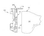
- FIG. 1is an exploded isometric view of the components of a chamfer resection guide assembly 100 according to an embodiment of the present disclosure.
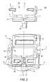
- FIG. 2is another partially exploded isometric view certain components of the chamfer resection guide assembly 100 of FIG. 1 .
- FIG. 3is a longitudinal cross-sectional view of the chamfer resection guide assembly 100 of FIG. 1 in a partially assembled state.
- FIG. 4is a longitudinal cross-sectional view of the chamfer resection guide assembly 100 of FIG. 1 in a fully assembled state.
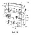
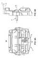
- FIG. 5Ais an isometric view of a fully assembled chamfer resection guide assembly 100 .
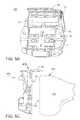
- FIGS. 5B and 5Care isometric view and a side view, respectively, of a fully assembled chamfer resection guide assembly according to another embodiment.
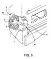
- FIG. 6is a detailed partial cross-sectional view of the camming member 20 situated in the block member 1 of the chamfer resection guide assembly 100 .
- FIGS. 7A-7Bare a plan view and a side view of the chamfer resection guide assembly 100 in a neutral position setting.
- FIGS. 8A-8Bare a plan view and a side view of the chamfer resection guide assembly 100 in a “+” position setting.
- FIGS. 9A-9Bare a plan view and a side view of the chamfer resection guide assembly 100 in a “ ⁇ ” position setting.
- FIG. 10is a detailed cross-sectional view of the guiderail structures 12 of the block member 1 and the male boss structures 13 of the anchor member 5 in an engaged configuration.
- FIGS. 11A-11Care schematic illustration of the camming action provided by the cam body 4 and the offset cylinder boss 15 of the camming member 20 .
- the chamfer resection guide 100comprises an anchor member 5 , a block member 1 , and a camming member 20 .
- the anchor member 5 and the block member 1are slidably engaged to each other and the camming member 20 operatively connects and controls the relative sliding motion of the anchor member 5 and the block member 1 .
- the block member 1comprises a plurality of slots 6 that function as guiding means for guiding a cutting tool 50 (See FIG. 4 ) for making various bone resections required for the final femoral implant.
- An oscillating sawis an example of a cutting tool.
- Each of the plurality of slots 6has an appropriate length and extends through the full thickness of the block member 1 at an angle that is appropriate for making a particular resection cut into the distal end of the femur.
- the block member 1has two major sides: a top side 30 , the side that faces away from the femoral bone when in use, and a femoral contacting surface 32 side.
- the side that faces the femur and has femoral contacting surfaces 32is attached to the distal resected surface of the femur during use.
- a recessed region 40is provided on the femoral contacting surface 32 of the block member 1 .
- the recessed region 40is cut into the femoral contacting surface 32 and is defined by a pair of guiderail structures 12 for engaging the anchor member 5 .
- the guiderail structures 12extend parallel to the longitudinal axis L of the chamfer resection guide assembly 100 .
- the recessed region 40extends along the longitudinal axis L and allows the anchor member 5 to slide linearly within the recessed region 40 parallel to the longitudinal axis L.
- To guiderail structures 12 and the anchor member 5are configured to slidably engage each other while preventing the anchor member 5 from moving in lateral directions (i.e. perpendicular to the longitudinal axis L).
- the guiderail structures 12are configured to have an undercut profile while the anchor member 5 is provided with corresponding male boss structures 13 along the sides that engage the guiderail structures 12 .
- These engaging structuresare shown in detail in the cross-sectional view in FIG. 10 .
- the particular configuration of the guiderail structures 12 and the male boss structures 13 illustrated hereinare only examples and other equivalent configurations are within the scope of the current disclosure.
- the anchor member 5When assembled and situated within the recessed region 40 of the block member 1 , the side of the anchor member 5 that faces in the same direction as the femoral contacting surface 32 will be referred to herein as the second femoral contacting surface 35 .
- the anchor member 5may be provided with an appropriate means for attaching or anchoring to the resected distal surface of the femur.
- two anchoring pins 8are provided on the second femoral contacting surface 35 of the anchor member 5 .
- the anchoring pins 8can be inserted into predrilled holes in the femur to attach the anchor member 5 and, thus, the chamfer resection guide assembly 100 to the resected distal surface of the femur.
- the camming member 20is captured between the anchor member 5 and the block member 1 .
- the camming member 20operably connects the anchor member 5 and the block member 1 and enables linear displacement of the block member 1 and the anchor member 5 with respect to each other.
- the camming member 20comprises an adjustment plunger 2 , a cam body 4 and a coil spring 3 .
- the adjustment plunger 2cooperates with the block member 1 and the cam body 4 cooperates with the anchor member 5 to effectuate a linear displacement of the block member 1 with respect to the anchor member 5 by operation of the cam 4 .
- the adjustment plunger 2has a first end 60 and a second end 61 .
- the first end 60 of the adjustment plunger 2is configured for being received into a first blind hole 45 provided in the recessed region 40 and cooperating with the block member 1 .
- the adjustment plunger 2 and the cam body 4are configured to couple together to rotate about the longitudinal axis LL of the camming member 20 in unison while translating axially with respect to each other. This coupling configuration is achieved by a motise and tenon joint.
- a tenon 9 structureis provided at the second end 61 of the adjustment plunger 2 that mates with a corresponding mortise 10 structure provided in the cam body 4 .
- the mortise and tenon jointtransfer rotational loads from the adjustment plunger 2 to the cam body 4 thus allowing them to rotate together while permitting the adjustment plunger 2 to translate axially when the adjustment plunger 2 is pushed towards the cam body 4 . It would be equally effective to swap the locations of the mortise 10 and the tenon 9 structures shown in the illustrated example. Alternatively, other functionally equivalent structures can be provided on the cam body 4 and the adjustment plunger 2 to form the coupling.
- the chamfer resection guide assembly 100is assembled by first assembling the camming member 20 components into the first blind hole 45 of the block member 1 .
- the adjustment plunger 2is inserted first into the first blind hole 45 and the coil spring 3 and the cam body 4 are inserted over the adjustment plunger 2 so that the coil spring 3 is contained between the adjustment plunger 2 and the cam body 4 .
- the dimension of the coil spring 3is such that a portion of the cam body 4 protrudes out of the first blind hole 45 .
- FIG. 2shows the camming member 20 assembled into the first blind hole 45 .
- FIG. 3shows an interim state where as the anchor member 5 is being slid into the recessed region 40 in the direction of the arrow B. In this interim state, the anchor member 5 is not yet fully inserted into the recessed region 40 and the anchor member 5 is covering the first blind hole 45 compressing the camming member 20 assembly.
- the anchor member 5is provided with a tab portion 55 that extend longitudinally for engaging the block member 1 .
- the block member 1is provided with a complementary slot 51 for receiving the tab portion 55 . In the fully assembled state shown in FIGS. 4 and 5A , the tab portion 55 is positioned in the slot 51 .
- the cam body 4comprises an offset cylinder boss 15 that fits into and engages the blind slot 14 of the anchor member 5 .
- This arrangementallows the chamfer resection guide assembly 100 to be held together as the offset cylinder boss 15 is always urged into the blind slot 14 of the anchor member 5 by the force of the coil spring 3 .
- a through hole 16may be provided in the anchor member 5 permitting access to the cam body 4 and allowing disassembly of the chamfer resection guide assembly 100 .
- the anchor member 5is provided with a blind slot 14 for receiving the offset cylinder boss 15 of the cam body 4 .
- the coil spring 3is configured to be in compression when the camming member 20 is captured between the anchor member 5 and the block member 1 and urge the cam body 4 and the adjustment plunger 2 outward against the anchor member 5 and the block member 1 , respectively.
- the coil spring 3may be substituted with any types of elastically compressible member that can provide the equivalent function.
- FIGS. 1 , 3 and 4the center of the offset cylinder boss 15 is offset from the center of the cam body 4 .
- the blind slot 14 of the anchor member 5is sized to receive the offset cylinder boss 15 of the cam body 4 .
- the offset configuration of the offset cylinder boss 15allows the offset cylinder boss 15 to act as a cam and move the anchor member 5 and the block member 1 with respect to each other in the anterior or posterior directions as noted by the arrow A.
- the maximum amount of displacement of the anchor member 5 and the block member 1 with respect to each otheris the function of the amount of the offset between the center of the cylinder boss 15 and the center of the cam body 4 .
- FIG. 5Ashows a fully assembled configuration of the chamfer resection guide assembly 100 .
- the adjustment plunger 2 and the first blind hole 45 of the block member 1are configured to allow controlled adjustment of the relative position of the block member 1 with respect to the anchor member 5 .
- the adjustment plunger 2is configured to have a mid-section 62 that is larger in diameter than the first end 60 and the second end 61 , as shown in FIGS. 3 and 4 . This mid-section 62 allows the coil spring 3 to be contained between the adjustment plunger 2 and the cam body 4 and interferes with a retaining lip 46 of the first blind hole 45 and retains the adjustment plunger 2 within the first blind hole 45 .
- the retaining lip 46 provided at the terminal end of the first blind hole 45 at the top side 30 of the block memberforms a hexagonal opening and the first end 60 of the adjustment plunger 2 has a matching hexagonal shape that fits into the hexagonal opening.
- the coil spring 3urges the adjustment plunger 2 against the retaining lip 46 and the hexagonal shape of the first end 60 and the opening formed by the retaining lip 46 keeps the first end 60 engaged in a locking manner with the retaining lip 46 and prevents the adjustment plunger 2 from turning about its longitudinal axis LL.
- the shape of the opening formed by the retaining lip 46 and the first end 60 of the adjustment plunger 2does not need to be limited to a hexagonal shape but any number of non-circular shapes would provide the same functionality.
- the adjustment plunger 2is pushed inward (i.e. away from the retaining lip 46 and towards the femoral contact surface 32 ) along its longitudinal axis LL compressing the coil spring 3 . This disengages the first end 60 of the adjustment plunger 2 from the retaining lip 46 of the first blind hole 45 and unlocks the adjustment plunger 2 allowing it to be turned.
- the chamfer resection guide assembly 100is configured to have three adjustment positions for the block member 1 using the hexagonal shape of the adjustment plunger 2 and the retaining lip 46 of the first blind hole 45 .
- the illustrated example chamfer resection guide 100is configured with three positions “+2”, “0” and “ ⁇ 2” noting the three possible positions for the block member 1 with respect to the anchor member 5 .
- the position “0”marks the neutral or the initial position 17 (see FIG. 7A ).
- FIG. 7Bshows the relative position of the block member 1 with respect to the reference position 70 of the anchor member 5 marked by the reference features, the anchoring pins 8 .
- the block member 1 and its resection guide slots 6are in their neutral position 71 with respect to the reference position 70 .
- the chamfer resection guide assembly 100would be attached to the distal resection of a femur with the adjustment plunger 2 in the neutral position “0.” Then, after the chamfer resection guide assembly 100 is attached to the distal resection of the femur by anchoring the anchor member 5 to the femur using reference features such as the anchoring pins 8 , the position of the resection guide slots 6 can be adjusted from the neutral position by turning the adjustment plunger 2 to one of the two alternate positions, “+2” or “ ⁇ 2”.
- the amount of the linear displacement of the block member 1is determined by the amount of the offset between the offset cylinder boss 15 and the cam body 4 and the amount of angular rotation made by the adjustment plunger 2 between the incremental adjustment positions.
- the incremental adjustment positionsare separated by 60° by virtue of the hexagonal configuration of the first end 60 of the adjustment plunger 2 . If a finer adjustment capability is desired, the first end 60 of the adjustment plunger 2 and the corresponding retaining lip 46 of the first blind hole 45 can be configured with shapes allowing finer incremental angular adjustment such as an octagon.
- FIGS. 11A-11CThe camming action provided by the rotation of the camming member 20 about its rotational axis, the longitudinal axis LL, is shown in FIGS. 11A-11C .
- FIG. 11Ashows the outlines of the cam body 4 , the offset cylinder boss 15 and the blind slot 14 (shown in dotted line) in the “neutral” position.
- the blind slot 14is configured with a dimension that the offset cylinder boss 15 fits within the blind slot 14 without undesirable space between the structures in the anterior/posterior directions (top to bottom direction as shown in FIGS. 11A-11C ).
- FIG. 11Ashows that the center 4 c of the cam body 4 and the center 15 c of the offset cylinder boss 15 are offset.
- FIG. 11Bshows the adjusted configuration after the camming member 20 is turned in the “+” offset direction.
- the offset cylinder boss 15has moved up and pushed the anchor member 5 up along with it as represented by the new position of the blind slot 14 .
- FIG. 11Cshows the adjusted configuration after the camming member 20 is turned in the “ ⁇ ” offset direction.
- the offset cylinder boss 15has moved down and pushed the anchor member 5 down along with it as represented by the new position of the blind slot 14 .
- the first end 60 of the adjustment plunger 2is preferably configured for receiving an adjustment tool, such as a screw driver or a wrench, that is used for pressing and turning the adjustment plunger 2 .
- an adjustment toolsuch as a screw driver or a wrench
- the first end 60 of adjustment plunger 2 according to the illustrated exampleis provided with a tool-receiving recess 63 for receiving a hex-key type tool.
- the camming memberoperatively connects the block member and the anchor member and is configured for linearly displacing the anchor member and the block member with respect to each other for adjusting the position of the anchor member within the recessed region of the block member.
- the anchor member 5When the chamfer resection guide assembly 100 is attached to the distal end of a femur the anchor member 5 is sandwiched between the resected surface of the femoral bone and the block member 1 .
- the anchor membermay be provided with appropriate number of clearance cutouts 7 for allowing the saw blade of the cutting tool to extend through the anchor member 5 when resections are being made through the guiding slots 6 .
- the clearance cutouts 7provide clearance for the guiding slots 6 a.
- FIGS. 5B and 5Ca chamfer resection guide assembly 200 according to another embodiment is shown.
- FIG. 5Bshows the fully assembled chamfer resection guide assembly 200
- FIG. 5Cshows a side view of the chamfer resection guide assembly 200 being attached to the resected distal surface 310 of a femur 300 .
- the chamfer resection guide assembly 200is configured for referencing the chamfer cuts to the resected anterior surface 320 of the femur 300 .
- the anchor member 5 a of this assemblydoes not have the anchoring pins 8 found on the anchor member 5 of the chamfer resection guide assembly 100 .
- anchor member 5 ais provided with a footplate extension 8 a that extends from the second femoral contacting surface 35 of the anchor member 5 a near the anterior end 210 of the chamfer resection guide assembly 200 .
- This configuration of anchor member 5 apermits another means of using of the device that references position and orientation without impeding the means to saw through the device.
- Various other configurations of the anchor member, 5 or 5 a, which perform the same referencing and functional tasks through other means not illustrated,may also be utilized.
- the chamfer resection guide assembly 200contacts the resected distal surface 310 of the femur 300 so that the second femoral contacting surface 35 of the anchor member 5 a is flush against the resected distal surface 310 of the femur 300 .
- the chamfer resection guide 200is positioned to have the footplate extension 8 a come in contact with the resected anterior surface 320 of the femur 300 . This allows anterior referencing of the chamfer cuts effected with the chamfer resection guide assembly 200 because the positions of the chamfer guiding slots 6 are referenced against the resected anterior surface 320 .
- the position of the chamfer resection guide of the present disclosurecan be adjusted in the anterior/posterior direction without removing and repositioning the instrument.
- the chamfer resection guide of the present disclosuresaves time and reduce potential error by leaving the appropriately chosen size chamfer resection guide in position and refining its final position through a mechanism that is conducive to a minimally invasive procedure.
- Other adjustment resection guides of a similar naturehave large knobs that could interfere with soft tissue.
- the adjustment mechanism of the chamfer resection guide of the present disclosureis self-contained within the chamfer resection guide and also simultaneously functions to hold the assembly of the instrument together.
- the chamfer resection guidecan be assembled without additional assembly processes such as crosspinning, welding, etc. This feature allows the assembly process for the instrument to be simpler and less costly.
Landscapes
- Health & Medical Sciences (AREA)
- Life Sciences & Earth Sciences (AREA)
- Surgery (AREA)
- Dentistry (AREA)
- Biomedical Technology (AREA)
- Oral & Maxillofacial Surgery (AREA)
- Nuclear Medicine, Radiotherapy & Molecular Imaging (AREA)
- Physical Education & Sports Medicine (AREA)
- Orthopedic Medicine & Surgery (AREA)
- Engineering & Computer Science (AREA)
- Transplantation (AREA)
- Heart & Thoracic Surgery (AREA)
- Medical Informatics (AREA)
- Molecular Biology (AREA)
- Animal Behavior & Ethology (AREA)
- General Health & Medical Sciences (AREA)
- Public Health (AREA)
- Veterinary Medicine (AREA)
- Surgical Instruments (AREA)
Abstract
Description
- a first end engaging the blind hole of the block member;
- a second end engaging the blind slot of the anchor member; and
- an elastically compressible member contained between the first end and the second end and urging the first end against the block member and the second end against the anchor member.
Claims (12)
Priority Applications (2)
| Application Number | Priority Date | Filing Date | Title |
|---|---|---|---|
| US13/658,351US8523870B2 (en) | 2009-08-20 | 2012-10-23 | Adjustable femoral resection guide |
| US13/943,384US8828015B2 (en) | 2009-08-20 | 2013-07-16 | Adjustable femoral resection guide |
Applications Claiming Priority (2)
| Application Number | Priority Date | Filing Date | Title |
|---|---|---|---|
| US12/544,279US8313491B2 (en) | 2009-08-20 | 2009-08-20 | Adjustable femoral resection guide |
| US13/658,351US8523870B2 (en) | 2009-08-20 | 2012-10-23 | Adjustable femoral resection guide |
Related Parent Applications (1)
| Application Number | Title | Priority Date | Filing Date |
|---|---|---|---|
| US12/544,279ContinuationUS8313491B2 (en) | 2009-08-20 | 2009-08-20 | Adjustable femoral resection guide |
Related Child Applications (1)
| Application Number | Title | Priority Date | Filing Date |
|---|---|---|---|
| US13/943,384ContinuationUS8828015B2 (en) | 2009-08-20 | 2013-07-16 | Adjustable femoral resection guide |
Publications (2)
| Publication Number | Publication Date |
|---|---|
| US20130046309A1 US20130046309A1 (en) | 2013-02-21 |
| US8523870B2true US8523870B2 (en) | 2013-09-03 |
Family
ID=43605933
Family Applications (3)
| Application Number | Title | Priority Date | Filing Date |
|---|---|---|---|
| US12/544,279Active2031-04-15US8313491B2 (en) | 2009-08-20 | 2009-08-20 | Adjustable femoral resection guide |
| US13/658,351ActiveUS8523870B2 (en) | 2009-08-20 | 2012-10-23 | Adjustable femoral resection guide |
| US13/943,384ActiveUS8828015B2 (en) | 2009-08-20 | 2013-07-16 | Adjustable femoral resection guide |
Family Applications Before (1)
| Application Number | Title | Priority Date | Filing Date |
|---|---|---|---|
| US12/544,279Active2031-04-15US8313491B2 (en) | 2009-08-20 | 2009-08-20 | Adjustable femoral resection guide |
Family Applications After (1)
| Application Number | Title | Priority Date | Filing Date |
|---|---|---|---|
| US13/943,384ActiveUS8828015B2 (en) | 2009-08-20 | 2013-07-16 | Adjustable femoral resection guide |
Country Status (1)
| Country | Link |
|---|---|
| US (3) | US8313491B2 (en) |
Cited By (35)
| Publication number | Priority date | Publication date | Assignee | Title |
|---|---|---|---|---|
| US8828015B2 (en)* | 2009-08-20 | 2014-09-09 | Microport Orthopedics Holdings Inc. | Adjustable femoral resection guide |
| US9622805B2 (en) | 2015-08-14 | 2017-04-18 | Treace Medical Concepts, Inc. | Bone positioning and preparing guide systems and methods |
| US9687250B2 (en) | 2015-01-07 | 2017-06-27 | Treace Medical Concepts, Inc. | Bone cutting guide systems and methods |
| US10342590B2 (en) | 2015-08-14 | 2019-07-09 | Treace Medical Concepts, Inc. | Tarsal-metatarsal joint procedure utilizing fulcrum |
| US10512470B1 (en) | 2016-08-26 | 2019-12-24 | Treace Medical Concepts, Inc. | Osteotomy procedure for correcting bone misalignment |
| US10524808B1 (en) | 2016-11-11 | 2020-01-07 | Treace Medical Concepts, Inc. | Devices and techniques for performing an osteotomy procedure on a first metatarsal to correct a bone misalignment |
| US10555757B2 (en) | 2014-07-15 | 2020-02-11 | Treace Medical Concepts, Inc. | Bone positioning and cutting system and method |
| US10575862B2 (en) | 2015-09-18 | 2020-03-03 | Treace Medical Concepts, Inc. | Joint spacer systems and methods |
| US10653467B2 (en) | 2015-05-06 | 2020-05-19 | Treace Medical Concepts, Inc. | Intra-osseous plate system and method |
| US10849631B2 (en) | 2015-02-18 | 2020-12-01 | Treace Medical Concepts, Inc. | Pivotable bone cutting guide useful for bone realignment and compression techniques |
| US10849663B2 (en) | 2015-07-14 | 2020-12-01 | Treace Medical Concepts, Inc. | Bone cutting guide systems and methods |
| US10874446B2 (en) | 2015-07-14 | 2020-12-29 | Treace Medical Concepts, Inc. | Bone positioning guide |
| US10939939B1 (en) | 2017-02-26 | 2021-03-09 | Treace Medical Concepts, Inc. | Fulcrum for tarsal-metatarsal joint procedure |
| US11278337B2 (en) | 2015-08-14 | 2022-03-22 | Treace Medical Concepts, Inc. | Tarsal-metatarsal joint procedure utilizing fulcrum |
| US11583323B2 (en) | 2018-07-12 | 2023-02-21 | Treace Medical Concepts, Inc. | Multi-diameter bone pin for installing and aligning bone fixation plate while minimizing bone damage |
| US11596443B2 (en) | 2018-07-11 | 2023-03-07 | Treace Medical Concepts, Inc. | Compressor-distractor for angularly realigning bone portions |
| US11607250B2 (en) | 2019-02-13 | 2023-03-21 | Treace Medical Concepts, Inc. | Tarsal-metatarsal joint procedure utilizing compressor-distractor and instrument providing sliding surface |
| US11622797B2 (en) | 2020-01-31 | 2023-04-11 | Treace Medical Concepts, Inc. | Metatarsophalangeal joint preparation and metatarsal realignment for fusion |
| US11627954B2 (en) | 2019-08-07 | 2023-04-18 | Treace Medical Concepts, Inc. | Bi-planar instrument for bone cutting and joint realignment procedure |
| USD1011524S1 (en) | 2022-02-23 | 2024-01-16 | Treace Medical Concepts, Inc. | Compressor-distractor for the foot |
| US11890039B1 (en) | 2019-09-13 | 2024-02-06 | Treace Medical Concepts, Inc. | Multi-diameter K-wire for orthopedic applications |
| US11889998B1 (en) | 2019-09-12 | 2024-02-06 | Treace Medical Concepts, Inc. | Surgical pin positioning lock |
| US11931106B2 (en) | 2019-09-13 | 2024-03-19 | Treace Medical Concepts, Inc. | Patient-specific surgical methods and instrumentation |
| US11986251B2 (en) | 2019-09-13 | 2024-05-21 | Treace Medical Concepts, Inc. | Patient-specific osteotomy instrumentation |
| US12004789B2 (en) | 2020-05-19 | 2024-06-11 | Treace Medical Concepts, Inc. | Devices and techniques for treating metatarsus adductus |
| USD1051382S1 (en) | 2022-02-23 | 2024-11-12 | Treace Medical Concepts, Inc. | Lesser metatarsal cut guide |
| US12161371B2 (en) | 2021-01-18 | 2024-12-10 | Treace Medical Concepts, Inc. | Contoured bone plate with locking screw for bone compression, particularly across a tarsometatarsal joint |
| USD1057155S1 (en) | 2022-02-23 | 2025-01-07 | Treace Medical Concepts, Inc. | Lesser metatarsal cut guide with parallel cut faces |
| US12193683B2 (en) | 2021-05-20 | 2025-01-14 | Treace Medical Concepts, Inc. | Cut guide with integrated joint realignment features |
| USD1068078S1 (en) | 2023-02-08 | 2025-03-25 | Treace Medical Concepts, Inc. | Handle for an orthopedic instrument |
| USD1068077S1 (en) | 2023-02-08 | 2025-03-25 | Treace Medical Concepts, Inc. | Orthopedic rasp for preparing an intercuneiform joint |
| USD1075012S1 (en) | 2022-02-23 | 2025-05-13 | Treace Medical Concepts, Inc. | Metatarsal lateral release instrument |
| US12310603B2 (en) | 2021-02-18 | 2025-05-27 | Treace Medical Concepts, Inc. | System and technique for metatarsal realignment with reduced incision length |
| USD1079011S1 (en) | 2022-02-23 | 2025-06-10 | Treace Medical Concepts, Inc. | Metatarsal cut guide with parallel cut faces |
| US12440250B2 (en) | 2024-02-05 | 2025-10-14 | Treace Medical Concepts, Inc. | Multi-diameter K-wire for orthopedic applications |
Families Citing this family (75)
| Publication number | Priority date | Publication date | Assignee | Title |
|---|---|---|---|---|
| US9113971B2 (en) | 2006-02-27 | 2015-08-25 | Biomet Manufacturing, Llc | Femoral acetabular impingement guide |
| US8407067B2 (en) | 2007-04-17 | 2013-03-26 | Biomet Manufacturing Corp. | Method and apparatus for manufacturing an implant |
| US8603180B2 (en) | 2006-02-27 | 2013-12-10 | Biomet Manufacturing, Llc | Patient-specific acetabular alignment guides |
| US8608749B2 (en) | 2006-02-27 | 2013-12-17 | Biomet Manufacturing, Llc | Patient-specific acetabular guides and associated instruments |
| US9173661B2 (en) | 2006-02-27 | 2015-11-03 | Biomet Manufacturing, Llc | Patient specific alignment guide with cutting surface and laser indicator |
| US9289253B2 (en) | 2006-02-27 | 2016-03-22 | Biomet Manufacturing, Llc | Patient-specific shoulder guide |
| US8568487B2 (en) | 2006-02-27 | 2013-10-29 | Biomet Manufacturing, Llc | Patient-specific hip joint devices |
| US9918740B2 (en) | 2006-02-27 | 2018-03-20 | Biomet Manufacturing, Llc | Backup surgical instrument system and method |
| US7967868B2 (en) | 2007-04-17 | 2011-06-28 | Biomet Manufacturing Corp. | Patient-modified implant and associated method |
| US9339278B2 (en) | 2006-02-27 | 2016-05-17 | Biomet Manufacturing, Llc | Patient-specific acetabular guides and associated instruments |
| US9345548B2 (en) | 2006-02-27 | 2016-05-24 | Biomet Manufacturing, Llc | Patient-specific pre-operative planning |
| US8535387B2 (en) | 2006-02-27 | 2013-09-17 | Biomet Manufacturing, Llc | Patient-specific tools and implants |
| US8591516B2 (en) | 2006-02-27 | 2013-11-26 | Biomet Manufacturing, Llc | Patient-specific orthopedic instruments |
| US9907659B2 (en) | 2007-04-17 | 2018-03-06 | Biomet Manufacturing, Llc | Method and apparatus for manufacturing an implant |
| US10278711B2 (en) | 2006-02-27 | 2019-05-07 | Biomet Manufacturing, Llc | Patient-specific femoral guide |
| US8377066B2 (en) | 2006-02-27 | 2013-02-19 | Biomet Manufacturing Corp. | Patient-specific elbow guides and associated methods |
| US8608748B2 (en) | 2006-02-27 | 2013-12-17 | Biomet Manufacturing, Llc | Patient specific guides |
| US20150335438A1 (en) | 2006-02-27 | 2015-11-26 | Biomet Manufacturing, Llc. | Patient-specific augments |
| US9795399B2 (en) | 2006-06-09 | 2017-10-24 | Biomet Manufacturing, Llc | Patient-specific knee alignment guide and associated method |
| GB2442441B (en) | 2006-10-03 | 2011-11-09 | Biomet Uk Ltd | Surgical instrument |
| DE102009028503B4 (en) | 2009-08-13 | 2013-11-14 | Biomet Manufacturing Corp. | Resection template for the resection of bones, method for producing such a resection template and operation set for performing knee joint surgery |
| US8632547B2 (en)* | 2010-02-26 | 2014-01-21 | Biomet Sports Medicine, Llc | Patient-specific osteotomy devices and methods |
| US9271744B2 (en) | 2010-09-29 | 2016-03-01 | Biomet Manufacturing, Llc | Patient-specific guide for partial acetabular socket replacement |
| US9968376B2 (en) | 2010-11-29 | 2018-05-15 | Biomet Manufacturing, Llc | Patient-specific orthopedic instruments |
| US9241745B2 (en) | 2011-03-07 | 2016-01-26 | Biomet Manufacturing, Llc | Patient-specific femoral version guide |
| US8715289B2 (en) | 2011-04-15 | 2014-05-06 | Biomet Manufacturing, Llc | Patient-specific numerically controlled instrument |
| US9675400B2 (en) | 2011-04-19 | 2017-06-13 | Biomet Manufacturing, Llc | Patient-specific fracture fixation instrumentation and method |
| US8668700B2 (en) | 2011-04-29 | 2014-03-11 | Biomet Manufacturing, Llc | Patient-specific convertible guides |
| US8956364B2 (en) | 2011-04-29 | 2015-02-17 | Biomet Manufacturing, Llc | Patient-specific partial knee guides and other instruments |
| US8532807B2 (en) | 2011-06-06 | 2013-09-10 | Biomet Manufacturing, Llc | Pre-operative planning and manufacturing method for orthopedic procedure |
| US9084618B2 (en) | 2011-06-13 | 2015-07-21 | Biomet Manufacturing, Llc | Drill guides for confirming alignment of patient-specific alignment guides |
| US20130001121A1 (en) | 2011-07-01 | 2013-01-03 | Biomet Manufacturing Corp. | Backup kit for a patient-specific arthroplasty kit assembly |
| US8764760B2 (en) | 2011-07-01 | 2014-07-01 | Biomet Manufacturing, Llc | Patient-specific bone-cutting guidance instruments and methods |
| US8597365B2 (en) | 2011-08-04 | 2013-12-03 | Biomet Manufacturing, Llc | Patient-specific pelvic implants for acetabular reconstruction |
| US9066734B2 (en) | 2011-08-31 | 2015-06-30 | Biomet Manufacturing, Llc | Patient-specific sacroiliac guides and associated methods |
| US9295497B2 (en) | 2011-08-31 | 2016-03-29 | Biomet Manufacturing, Llc | Patient-specific sacroiliac and pedicle guides |
| US9386993B2 (en) | 2011-09-29 | 2016-07-12 | Biomet Manufacturing, Llc | Patient-specific femoroacetabular impingement instruments and methods |
| WO2013062848A1 (en) | 2011-10-27 | 2013-05-02 | Biomet Manufacturing Corporation | Patient-specific glenoid guides |
| US9451973B2 (en) | 2011-10-27 | 2016-09-27 | Biomet Manufacturing, Llc | Patient specific glenoid guide |
| US9301812B2 (en) | 2011-10-27 | 2016-04-05 | Biomet Manufacturing, Llc | Methods for patient-specific shoulder arthroplasty |
| US9554910B2 (en) | 2011-10-27 | 2017-01-31 | Biomet Manufacturing, Llc | Patient-specific glenoid guide and implants |
| KR20130046337A (en) | 2011-10-27 | 2013-05-07 | 삼성전자주식회사 | Multi-view device and contol method thereof, display apparatus and contol method thereof, and display system |
| WO2013078206A1 (en)* | 2011-11-21 | 2013-05-30 | Smith & Nephew, Inc. | Methods of designing molds for machining cost reduction |
| US9237950B2 (en) | 2012-02-02 | 2016-01-19 | Biomet Manufacturing, Llc | Implant with patient-specific porous structure |
| US9839462B2 (en) | 2012-02-06 | 2017-12-12 | Arthrex, Inc. | Surgical cutting block |
| US8808298B2 (en) | 2012-05-18 | 2014-08-19 | Zimmer, Inc. | Pivoting cut guides |
| US20140005672A1 (en)* | 2012-06-30 | 2014-01-02 | Jon M. Edwards | Cutting block including modular mounting systems |
| EP2884910A4 (en)* | 2012-08-09 | 2016-06-01 | Smith & Nephew Inc | TOTAL KNEE ARTHROPLASTY ADAPTED TO A PATIENT |
| US9060788B2 (en) | 2012-12-11 | 2015-06-23 | Biomet Manufacturing, Llc | Patient-specific acetabular guide for anterior approach |
| US9204977B2 (en) | 2012-12-11 | 2015-12-08 | Biomet Manufacturing, Llc | Patient-specific acetabular guide for anterior approach |
| US20140207143A1 (en)* | 2013-01-24 | 2014-07-24 | Michael Lee | Allograft templates and methods of use |
| US9839438B2 (en) | 2013-03-11 | 2017-12-12 | Biomet Manufacturing, Llc | Patient-specific glenoid guide with a reusable guide holder |
| US9579107B2 (en) | 2013-03-12 | 2017-02-28 | Biomet Manufacturing, Llc | Multi-point fit for patient specific guide |
| US9498233B2 (en) | 2013-03-13 | 2016-11-22 | Biomet Manufacturing, Llc. | Universal acetabular guide and associated hardware |
| US9826981B2 (en) | 2013-03-13 | 2017-11-28 | Biomet Manufacturing, Llc | Tangential fit of patient-specific guides |
| US9517145B2 (en) | 2013-03-15 | 2016-12-13 | Biomet Manufacturing, Llc | Guide alignment system and method |
| US20150112349A1 (en) | 2013-10-21 | 2015-04-23 | Biomet Manufacturing, Llc | Ligament Guide Registration |
| US10282488B2 (en) | 2014-04-25 | 2019-05-07 | Biomet Manufacturing, Llc | HTO guide with optional guided ACL/PCL tunnels |
| US9408616B2 (en) | 2014-05-12 | 2016-08-09 | Biomet Manufacturing, Llc | Humeral cut guide |
| US9839436B2 (en) | 2014-06-03 | 2017-12-12 | Biomet Manufacturing, Llc | Patient-specific glenoid depth control |
| US9561040B2 (en) | 2014-06-03 | 2017-02-07 | Biomet Manufacturing, Llc | Patient-specific glenoid depth control |
| CN105310743B (en)* | 2014-07-09 | 2017-11-21 | 北京纳通科技集团有限公司 | A kind of osteotomy guider |
| US9826994B2 (en) | 2014-09-29 | 2017-11-28 | Biomet Manufacturing, Llc | Adjustable glenoid pin insertion guide |
| US9833245B2 (en) | 2014-09-29 | 2017-12-05 | Biomet Sports Medicine, Llc | Tibial tubercule osteotomy |
| US9820868B2 (en) | 2015-03-30 | 2017-11-21 | Biomet Manufacturing, Llc | Method and apparatus for a pin apparatus |
| US10568647B2 (en) | 2015-06-25 | 2020-02-25 | Biomet Manufacturing, Llc | Patient-specific humeral guide designs |
| US10226262B2 (en) | 2015-06-25 | 2019-03-12 | Biomet Manufacturing, Llc | Patient-specific humeral guide designs |
| JP6744392B2 (en)* | 2015-07-07 | 2020-08-19 | ジンマー,インコーポレイティド | Femur finishing guide |
| US10722310B2 (en) | 2017-03-13 | 2020-07-28 | Zimmer Biomet CMF and Thoracic, LLC | Virtual surgery planning system and method |
| US10905445B2 (en) | 2017-05-11 | 2021-02-02 | Zimmer Gmbh | Adjustable cutting block for knee arthroplasty |
| CN110301958B (en)* | 2018-03-27 | 2022-05-20 | 苏州微创关节医疗科技有限公司 | Osteotomy device |
| JP7353059B2 (en)* | 2019-03-29 | 2023-09-29 | 京セラ株式会社 | surgical instruments |
| CA3114820C (en)* | 2020-04-16 | 2023-10-03 | Orthosoft Ulc | Devices and methods for posterior resection in robotically assisted partial knee arthroplasties |
| CN111616771A (en)* | 2020-06-28 | 2020-09-04 | 经纬医疗器材制造(深圳)有限公司 | An adjustable osteotomy |
| CN115429378A (en)* | 2022-09-28 | 2022-12-06 | 北京纳通医疗科技控股有限公司 | Osteotomy instrument |
Citations (17)
| Publication number | Priority date | Publication date | Assignee | Title |
|---|---|---|---|---|
| EP0121780A1 (en) | 1983-03-09 | 1984-10-17 | Dow Corning Corporation | Apparatus for shaping a distal femoral surface |
| US4926847A (en) | 1988-12-27 | 1990-05-22 | Johnson & Johnson Orthopaedics, Inc. | Surgical cutting block |
| US5486178A (en) | 1994-02-16 | 1996-01-23 | Hodge; W. Andrew | Femoral preparation instrumentation system and method |
| US5662656A (en) | 1995-12-08 | 1997-09-02 | Wright Medical Technology, Inc. | Instrumentation and method for distal femoral sizing, and anterior and distal femoral resections |
| US5709689A (en) | 1995-09-25 | 1998-01-20 | Wright Medical Technology, Inc. | Distal femur multiple resection guide |
| US5810831A (en) | 1994-02-16 | 1998-09-22 | Osteonics Corp. | Femoral sizing guide and method |
| US6013081A (en) | 1998-09-09 | 2000-01-11 | Sulzer Orthopedics Inc. | Apparatus and method for anterior and posterior referenced sizing and distal femur resection |
| US6059788A (en) | 1995-05-31 | 2000-05-09 | Katz; Lawrence | Method and apparatus for locating bone cuts at the distal condylar femur region to receive a femoral prosthesis and properly articulated with patellar and tibial prosthesis |
| US6440140B2 (en) | 2000-01-31 | 2002-08-27 | Medacta S.A. | Ancillary apparatus for knee prosthesis |
| US6500179B1 (en) | 1998-02-02 | 2002-12-31 | Medidea, Llc | Bone cutting guide and method to accommodate different-sized implants |
| US20060142778A1 (en) | 2004-12-21 | 2006-06-29 | Dees Roger R Jr | Rotational alignment femoral sizing guide |
| US20060217734A1 (en) | 2005-03-09 | 2006-09-28 | Zimmer Technology, Inc. | Femoral resection guide apparatus and method |
| US7182767B2 (en) | 2004-05-19 | 2007-02-27 | Howmedica Osteonics Corp. | Navigated lateral/medial femoral resection guide |
| US20070173851A1 (en) | 2006-01-12 | 2007-07-26 | Howmedica Osteonics Corp. | Modular anterior-posterior femoral sizer |
| US20070233140A1 (en) | 2006-02-27 | 2007-10-04 | Biomet Manufacturing Corp. | Femoral adjustment device and associated method |
| US20080161824A1 (en) | 2006-12-27 | 2008-07-03 | Howmedica Osteonics Corp. | System and method for performing femoral sizing through navigation |
| US20100324563A1 (en) | 2009-06-19 | 2010-12-23 | Wright Medical Technology, Inc. | Midline referencing femoral sizing caliper |
Family Cites Families (1)
| Publication number | Priority date | Publication date | Assignee | Title |
|---|---|---|---|---|
| US8313491B2 (en)* | 2009-08-20 | 2012-11-20 | Wright Medical Technology, Inc. | Adjustable femoral resection guide |
- 2009
- 2009-08-20USUS12/544,279patent/US8313491B2/enactiveActive
- 2012
- 2012-10-23USUS13/658,351patent/US8523870B2/enactiveActive
- 2013
- 2013-07-16USUS13/943,384patent/US8828015B2/enactiveActive
Patent Citations (18)
| Publication number | Priority date | Publication date | Assignee | Title |
|---|---|---|---|---|
| EP0121780A1 (en) | 1983-03-09 | 1984-10-17 | Dow Corning Corporation | Apparatus for shaping a distal femoral surface |
| US4926847A (en) | 1988-12-27 | 1990-05-22 | Johnson & Johnson Orthopaedics, Inc. | Surgical cutting block |
| US5486178A (en) | 1994-02-16 | 1996-01-23 | Hodge; W. Andrew | Femoral preparation instrumentation system and method |
| US5810831A (en) | 1994-02-16 | 1998-09-22 | Osteonics Corp. | Femoral sizing guide and method |
| US6059788A (en) | 1995-05-31 | 2000-05-09 | Katz; Lawrence | Method and apparatus for locating bone cuts at the distal condylar femur region to receive a femoral prosthesis and properly articulated with patellar and tibial prosthesis |
| US5709689A (en) | 1995-09-25 | 1998-01-20 | Wright Medical Technology, Inc. | Distal femur multiple resection guide |
| US5662656A (en) | 1995-12-08 | 1997-09-02 | Wright Medical Technology, Inc. | Instrumentation and method for distal femoral sizing, and anterior and distal femoral resections |
| US6500179B1 (en) | 1998-02-02 | 2002-12-31 | Medidea, Llc | Bone cutting guide and method to accommodate different-sized implants |
| US6013081A (en) | 1998-09-09 | 2000-01-11 | Sulzer Orthopedics Inc. | Apparatus and method for anterior and posterior referenced sizing and distal femur resection |
| US6440140B2 (en) | 2000-01-31 | 2002-08-27 | Medacta S.A. | Ancillary apparatus for knee prosthesis |
| US7182767B2 (en) | 2004-05-19 | 2007-02-27 | Howmedica Osteonics Corp. | Navigated lateral/medial femoral resection guide |
| US20070123900A1 (en) | 2004-05-19 | 2007-05-31 | Howmedica Osteonics Corp. | Navigated lateral/medial femoral resection guide |
| US20060142778A1 (en) | 2004-12-21 | 2006-06-29 | Dees Roger R Jr | Rotational alignment femoral sizing guide |
| US20060217734A1 (en) | 2005-03-09 | 2006-09-28 | Zimmer Technology, Inc. | Femoral resection guide apparatus and method |
| US20070173851A1 (en) | 2006-01-12 | 2007-07-26 | Howmedica Osteonics Corp. | Modular anterior-posterior femoral sizer |
| US20070233140A1 (en) | 2006-02-27 | 2007-10-04 | Biomet Manufacturing Corp. | Femoral adjustment device and associated method |
| US20080161824A1 (en) | 2006-12-27 | 2008-07-03 | Howmedica Osteonics Corp. | System and method for performing femoral sizing through navigation |
| US20100324563A1 (en) | 2009-06-19 | 2010-12-23 | Wright Medical Technology, Inc. | Midline referencing femoral sizing caliper |
Cited By (82)
| Publication number | Priority date | Publication date | Assignee | Title |
|---|---|---|---|---|
| US8828015B2 (en)* | 2009-08-20 | 2014-09-09 | Microport Orthopedics Holdings Inc. | Adjustable femoral resection guide |
| US12349941B2 (en) | 2014-07-15 | 2025-07-08 | Treace Medical Concepts, Inc. | Bone positioning and cutting system and method |
| US10555757B2 (en) | 2014-07-15 | 2020-02-11 | Treace Medical Concepts, Inc. | Bone positioning and cutting system and method |
| US11937849B2 (en) | 2014-07-15 | 2024-03-26 | Treace Medical Concepts, Inc. | Bone positioning and cutting system and method |
| US10945764B2 (en) | 2014-07-15 | 2021-03-16 | Treace Medical Concepts, Inc. | Bone positioning and cutting system and method |
| US11147590B2 (en) | 2014-07-15 | 2021-10-19 | Treace Medical Concepts, Inc. | Bone positioning and cutting system and method |
| US11497528B2 (en) | 2014-07-15 | 2022-11-15 | Treace Medical Concepts, Inc. | Bone positioning and cutting system and method |
| US11523845B2 (en) | 2014-07-15 | 2022-12-13 | Treace Medical Concepts, Inc. | Bone positioning and cutting system and method |
| US11771467B2 (en) | 2014-07-15 | 2023-10-03 | Treace Medical Concepts, Inc. | Bone positioning and cutting system and method |
| US10561426B1 (en) | 2015-01-07 | 2020-02-18 | Treace Medical Concepts, Inc. | Bone cutting guide systems and methods |
| US12268397B2 (en) | 2015-01-07 | 2025-04-08 | Treace Medical Concepts, Inc. | Bone cutting guide systems and methods |
| US9687250B2 (en) | 2015-01-07 | 2017-06-27 | Treace Medical Concepts, Inc. | Bone cutting guide systems and methods |
| US11786257B2 (en) | 2015-01-07 | 2023-10-17 | Treace Medical Concepts, Inc. | Bone cutting guide systems and methods |
| US10603046B2 (en) | 2015-01-07 | 2020-03-31 | Treace Medical Concepts, Inc. | Bone cutting guide systems and methods |
| US10888335B2 (en) | 2015-01-07 | 2021-01-12 | Treace Medical Concepts, Inc. | Bone cutting guide systems and methods |
| US11844533B2 (en) | 2015-02-18 | 2023-12-19 | Treace Medical Concepts, Inc. | Pivotable bone cutting guide useful for bone realignment and compression techniques |
| US10849631B2 (en) | 2015-02-18 | 2020-12-01 | Treace Medical Concepts, Inc. | Pivotable bone cutting guide useful for bone realignment and compression techniques |
| US10653467B2 (en) | 2015-05-06 | 2020-05-19 | Treace Medical Concepts, Inc. | Intra-osseous plate system and method |
| US12396771B2 (en) | 2015-05-06 | 2025-08-26 | Treace Medical Concepts, Inc. | Intra-osseous plate system and method |
| US11969193B2 (en) | 2015-05-06 | 2024-04-30 | Treace Medical Concepts, Inc. | Intra-osseous plate system and method |
| US11426219B2 (en) | 2015-05-06 | 2022-08-30 | Treace Medical Concepts, Inc. | Intra-osseous plate system and method |
| US11116558B2 (en) | 2015-07-14 | 2021-09-14 | Treace Medical Concepts, Inc. | Bone positioning guide |
| US10874446B2 (en) | 2015-07-14 | 2020-12-29 | Treace Medical Concepts, Inc. | Bone positioning guide |
| US9936994B2 (en) | 2015-07-14 | 2018-04-10 | Treace Medical Concepts, Inc. | Bone positioning guide |
| US11950819B2 (en) | 2015-07-14 | 2024-04-09 | Treace Medical Concepts, Inc. | Bone positioning guide |
| US10335220B2 (en) | 2015-07-14 | 2019-07-02 | Treace Medical Concepts, Inc. | Bone positioning guide |
| US11185359B2 (en) | 2015-07-14 | 2021-11-30 | Treace Medical Concepts, Inc. | Bone positioning guide |
| US11963703B2 (en) | 2015-07-14 | 2024-04-23 | Treace Medical Concepts, Inc. | Bone cutting guide systems and methods |
| US10849663B2 (en) | 2015-07-14 | 2020-12-01 | Treace Medical Concepts, Inc. | Bone cutting guide systems and methods |
| US11602386B2 (en) | 2015-07-14 | 2023-03-14 | Treace Medical Concepts, Inc. | Bone positioning guide |
| US12102368B2 (en) | 2015-07-14 | 2024-10-01 | Treace Medical Concepts, Inc. | Bone positioning guide |
| US11213333B2 (en) | 2015-08-14 | 2022-01-04 | Treace Medical Concepts, Inc. | Bone positioning and preparing guide systems and methods |
| US11690659B2 (en) | 2015-08-14 | 2023-07-04 | Treace Medical Concepts, Inc. | Tarsal-metatarsal joint procedure utilizing fulcrum |
| US9622805B2 (en) | 2015-08-14 | 2017-04-18 | Treace Medical Concepts, Inc. | Bone positioning and preparing guide systems and methods |
| US11413081B2 (en) | 2015-08-14 | 2022-08-16 | Treace Medical Concepts, Inc. | Tarsal-metatarsal joint procedure utilizing fulcrum |
| US12274481B2 (en) | 2015-08-14 | 2025-04-15 | Treace Medical Concepts, Inc. | Bone positioning and preparing guide systems and methods |
| US10849670B2 (en) | 2015-08-14 | 2020-12-01 | Treace Medical Concepts, Inc. | Bone positioning and preparing guide systems and methods |
| US11602387B2 (en) | 2015-08-14 | 2023-03-14 | Treace Medical Concepts, Inc. | Bone positioning and preparing guide systems and methods |
| US11278337B2 (en) | 2015-08-14 | 2022-03-22 | Treace Medical Concepts, Inc. | Tarsal-metatarsal joint procedure utilizing fulcrum |
| US10045807B2 (en) | 2015-08-14 | 2018-08-14 | Treace Medical Concepts, Inc. | Bone positioning and preparing guide systems and methods |
| US11911085B2 (en) | 2015-08-14 | 2024-02-27 | Treace Medical Concepts, Inc. | Bone positioning and preparing guide systems and methods |
| US11039873B2 (en) | 2015-08-14 | 2021-06-22 | Treace Medical Concepts, Inc. | Bone positioning and preparing guide systems and methods |
| US12268428B2 (en) | 2015-08-14 | 2025-04-08 | Treace Medical Concepts, Inc. | Tarsal-metatarsal joint procedure utilizing fulcrum |
| US10342590B2 (en) | 2015-08-14 | 2019-07-09 | Treace Medical Concepts, Inc. | Tarsal-metatarsal joint procedure utilizing fulcrum |
| US11771443B2 (en) | 2015-09-18 | 2023-10-03 | Treace Medical Concepts, Inc. | Joint spacer systems and methods |
| US11648019B2 (en) | 2015-09-18 | 2023-05-16 | Treace Medical Concepts, Inc. | Joint spacer systems and methods |
| US12349927B2 (en) | 2015-09-18 | 2025-07-08 | Treace Medical Concepts, Inc. | Joint spacer systems and methods |
| US10575862B2 (en) | 2015-09-18 | 2020-03-03 | Treace Medical Concepts, Inc. | Joint spacer systems and methods |
| US10512470B1 (en) | 2016-08-26 | 2019-12-24 | Treace Medical Concepts, Inc. | Osteotomy procedure for correcting bone misalignment |
| US11076863B1 (en) | 2016-08-26 | 2021-08-03 | Treace Medical Concepts, Inc. | Osteotomy procedure for correcting bone misalignment |
| US11931047B2 (en) | 2016-08-26 | 2024-03-19 | Treace Medical Concepts, Inc. | Osteotomy procedure for correcting bone misalignment |
| US10582936B1 (en) | 2016-11-11 | 2020-03-10 | Treace Medical Concepts, Inc. | Devices and techniques for performing an osteotomy procedure on a first metatarsal to correct a bone misalignment |
| US10524808B1 (en) | 2016-11-11 | 2020-01-07 | Treace Medical Concepts, Inc. | Devices and techniques for performing an osteotomy procedure on a first metatarsal to correct a bone misalignment |
| US12414779B2 (en) | 2016-11-11 | 2025-09-16 | Treace Medical Concepts, Inc. | Devices and techniques for performing an osteotomy procedure on a first metatarsal to correct a bone misalignment |
| US11364037B2 (en) | 2016-11-11 | 2022-06-21 | Treace Medical Concepts, Inc. | Techniques for performing an osteotomy procedure on bone to correct a bone misalignment |
| US12357347B2 (en) | 2017-02-26 | 2025-07-15 | Treace Medical Concepts, Inc. | Fulcrum for tarsal-metatarsal joint procedure |
| US10939939B1 (en) | 2017-02-26 | 2021-03-09 | Treace Medical Concepts, Inc. | Fulcrum for tarsal-metatarsal joint procedure |
| US11596443B2 (en) | 2018-07-11 | 2023-03-07 | Treace Medical Concepts, Inc. | Compressor-distractor for angularly realigning bone portions |
| US11583323B2 (en) | 2018-07-12 | 2023-02-21 | Treace Medical Concepts, Inc. | Multi-diameter bone pin for installing and aligning bone fixation plate while minimizing bone damage |
| US11607250B2 (en) | 2019-02-13 | 2023-03-21 | Treace Medical Concepts, Inc. | Tarsal-metatarsal joint procedure utilizing compressor-distractor and instrument providing sliding surface |
| US12279794B2 (en) | 2019-02-13 | 2025-04-22 | Treace Medical Concepts, Inc. | Tarsal-metatarsal joint procedure utilizing compressor-distractor and instrument providing sliding surface |
| US11627954B2 (en) | 2019-08-07 | 2023-04-18 | Treace Medical Concepts, Inc. | Bi-planar instrument for bone cutting and joint realignment procedure |
| US12251091B2 (en) | 2019-08-07 | 2025-03-18 | Treace Medical Concepts, Inc. | Bi-planar instrument for bone cutting and joint realignment procedure |
| US11889998B1 (en) | 2019-09-12 | 2024-02-06 | Treace Medical Concepts, Inc. | Surgical pin positioning lock |
| US11931106B2 (en) | 2019-09-13 | 2024-03-19 | Treace Medical Concepts, Inc. | Patient-specific surgical methods and instrumentation |
| US11890039B1 (en) | 2019-09-13 | 2024-02-06 | Treace Medical Concepts, Inc. | Multi-diameter K-wire for orthopedic applications |
| US11986251B2 (en) | 2019-09-13 | 2024-05-21 | Treace Medical Concepts, Inc. | Patient-specific osteotomy instrumentation |
| US11622797B2 (en) | 2020-01-31 | 2023-04-11 | Treace Medical Concepts, Inc. | Metatarsophalangeal joint preparation and metatarsal realignment for fusion |
| US12364522B2 (en) | 2020-01-31 | 2025-07-22 | Treace Medical Concepts, Inc. | Metatarsophalangeal joint preparation and metatarsal realignment for fusion |
| US12396770B2 (en) | 2020-05-19 | 2025-08-26 | Treace Medical Concepts, Inc. | Devices and techniques for treating metatarsus adductus |
| US12004789B2 (en) | 2020-05-19 | 2024-06-11 | Treace Medical Concepts, Inc. | Devices and techniques for treating metatarsus adductus |
| US12161371B2 (en) | 2021-01-18 | 2024-12-10 | Treace Medical Concepts, Inc. | Contoured bone plate with locking screw for bone compression, particularly across a tarsometatarsal joint |
| US12310603B2 (en) | 2021-02-18 | 2025-05-27 | Treace Medical Concepts, Inc. | System and technique for metatarsal realignment with reduced incision length |
| US12193683B2 (en) | 2021-05-20 | 2025-01-14 | Treace Medical Concepts, Inc. | Cut guide with integrated joint realignment features |
| USD1079011S1 (en) | 2022-02-23 | 2025-06-10 | Treace Medical Concepts, Inc. | Metatarsal cut guide with parallel cut faces |
| USD1075012S1 (en) | 2022-02-23 | 2025-05-13 | Treace Medical Concepts, Inc. | Metatarsal lateral release instrument |
| USD1051382S1 (en) | 2022-02-23 | 2024-11-12 | Treace Medical Concepts, Inc. | Lesser metatarsal cut guide |
| USD1057155S1 (en) | 2022-02-23 | 2025-01-07 | Treace Medical Concepts, Inc. | Lesser metatarsal cut guide with parallel cut faces |
| USD1011524S1 (en) | 2022-02-23 | 2024-01-16 | Treace Medical Concepts, Inc. | Compressor-distractor for the foot |
| USD1068077S1 (en) | 2023-02-08 | 2025-03-25 | Treace Medical Concepts, Inc. | Orthopedic rasp for preparing an intercuneiform joint |
| USD1068078S1 (en) | 2023-02-08 | 2025-03-25 | Treace Medical Concepts, Inc. | Handle for an orthopedic instrument |
| US12440250B2 (en) | 2024-02-05 | 2025-10-14 | Treace Medical Concepts, Inc. | Multi-diameter K-wire for orthopedic applications |
Also Published As
| Publication number | Publication date |
|---|---|
| US20130046309A1 (en) | 2013-02-21 |
| US8313491B2 (en) | 2012-11-20 |
| US20130304071A1 (en) | 2013-11-14 |
| US8828015B2 (en) | 2014-09-09 |
| US20110046629A1 (en) | 2011-02-24 |
Similar Documents
| Publication | Publication Date | Title |
|---|---|---|
| US8523870B2 (en) | Adjustable femoral resection guide | |
| US12096948B2 (en) | Ankle replacement system and method | |
| US11759215B2 (en) | Ankle replacement system and method | |
| US20240382221A1 (en) | Ankle replacement system and method | |
| US11864778B2 (en) | Ankle replacement system and method | |
| US11786260B2 (en) | Ankle replacement system and method | |
| US10034672B2 (en) | Surgical cutting guide | |
| EP2563284B1 (en) | Alignment tool | |
| US5474559A (en) | Femoral milling instrumentation for use in total knee arthroplasty with optional cutting guide attachment | |
| US5860981A (en) | Guide for femoral milling instrumention for use in total knee arthroplasty | |
| JP5270352B2 (en) | Fixture assembly | |
| CN101415371B (en) | Orthopaedic cutting guide instrument | |
| CN107252338B (en) | Method and apparatus for performing knee arthroplasty | |
| JP2008531088A (en) | Instrument for aligning fixing screws | |
| US20190059913A1 (en) | Ankle arthroplasty systems and methods | |
| EP4013317B1 (en) | Drill assembly for preparation of surgical sites | |
| JP2013521991A (en) | Lockable orientation device assembly | |
| CN118141461A (en) | Knee joint osteotomy device | |
| US12396737B2 (en) | Chamfer guidance systems and methods | |
| CN114948156B (en) | Universal intramedullary nail fixing system | |
| CN120477873A (en) | Osteotomy positioning and pressurizing system |
Legal Events
| Date | Code | Title | Description |
|---|---|---|---|
| STCF | Information on status: patent grant | Free format text:PATENTED CASE | |
| AS | Assignment | Owner name:OTSUKA MEDICAL DEVICES CO., LTD., JAPAN Free format text:PATENT SECURITY AGREEMENT SUPPLEMENT;ASSIGNOR:MICROPORT ORTHOPEDICS HOLDINGS INC.;REEL/FRAME:031968/0377 Effective date:20140108 | |
| AS | Assignment | Owner name:WRIGHT MEDICAL TECHNOLOGY, INC., TENNESSEE Free format text:ASSIGNMENT OF ASSIGNORS INTEREST;ASSIGNORS:GREEN, JOHN MICHAEL, II;HARNESS, DAVID BRADFORD;REEL/FRAME:032091/0632 Effective date:20090901 | |
| AS | Assignment | Owner name:MICROPORT ORTHOPEDICS HOLDINGS INC., NETHERLANDS Free format text:ASSIGNMENT OF ASSIGNORS INTEREST;ASSIGNOR:WRIGHT MEDICAL TECHNOLOGY, INC.;REEL/FRAME:032410/0254 Effective date:20140106 | |
| FPAY | Fee payment | Year of fee payment:4 | |
| AS | Assignment | Owner name:MICROPORT ORTHOPEDICS HOLDINGS INC., TENNESSEE Free format text:RELEASE BY SECURED PARTY;ASSIGNOR:OTSUKA MEDICAL DEVICES CO., LTD.;REEL/FRAME:044772/0708 Effective date:20170810 | |
| MAFP | Maintenance fee payment | Free format text:PAYMENT OF MAINTENANCE FEE, 8TH YEAR, LARGE ENTITY (ORIGINAL EVENT CODE: M1552); ENTITY STATUS OF PATENT OWNER: LARGE ENTITY Year of fee payment:8 | |
| MAFP | Maintenance fee payment | Free format text:PAYMENT OF MAINTENANCE FEE, 12TH YEAR, LARGE ENTITY (ORIGINAL EVENT CODE: M1553); ENTITY STATUS OF PATENT OWNER: LARGE ENTITY Year of fee payment:12 |