US8523826B2 - Luer-type needle-free valve fitting with bypass - Google Patents
Luer-type needle-free valve fitting with bypassDownload PDFInfo
- Publication number
- US8523826B2 US8523826B2US12/371,346US37134609AUS8523826B2US 8523826 B2US8523826 B2US 8523826B2US 37134609 AUS37134609 AUS 37134609AUS 8523826 B2US8523826 B2US 8523826B2
- Authority
- US
- United States
- Prior art keywords
- collar
- diaphragm
- valve
- passageway
- closed
- Prior art date
- Legal status (The legal status is an assumption and is not a legal conclusion. Google has not performed a legal analysis and makes no representation as to the accuracy of the status listed.)
- Expired - Fee Related, expires
Links
- 239000012530fluidSubstances0.000claimsdescription50
- 230000001954sterilising effectEffects0.000claimsdescription35
- 238000004659sterilization and disinfectionMethods0.000claimsdescription30
- 238000000034methodMethods0.000claimsdescription27
- IAYPIBMASNFSPL-UHFFFAOYSA-NEthylene oxideChemical groupC1CO1IAYPIBMASNFSPL-UHFFFAOYSA-N0.000claimsdescription15
- 239000003795chemical substances by applicationSubstances0.000claimsdescription13
- 230000004044responseEffects0.000claimsdescription6
- 238000004891communicationMethods0.000claimsdescription2
- 238000004519manufacturing processMethods0.000abstractdescription4
- 239000003206sterilizing agentSubstances0.000abstractdescription4
- 239000007789gasSubstances0.000description24
- 239000000047productSubstances0.000description14
- 239000000463materialSubstances0.000description10
- 230000008569processEffects0.000description8
- 238000007789sealingMethods0.000description6
- 238000004806packaging method and processMethods0.000description5
- 238000012546transferMethods0.000description5
- MHAJPDPJQMAIIY-UHFFFAOYSA-NHydrogen peroxideChemical compoundOOMHAJPDPJQMAIIY-UHFFFAOYSA-N0.000description4
- OSVXSBDYLRYLIG-UHFFFAOYSA-Ndioxidochlorine(.)Chemical compoundO=Cl=OOSVXSBDYLRYLIG-UHFFFAOYSA-N0.000description4
- 229920001971elastomerPolymers0.000description4
- 230000036541healthEffects0.000description4
- -1polyethylenePolymers0.000description4
- 230000000994depressogenic effectEffects0.000description3
- 239000003814drugSubstances0.000description3
- 239000007788liquidSubstances0.000description3
- 229920001343polytetrafluoroethylenePolymers0.000description3
- 239000004810polytetrafluoroethyleneSubstances0.000description3
- 238000012414sterilization procedureMethods0.000description3
- 239000004155Chlorine dioxideSubstances0.000description2
- 208000012266Needlestick injuryDiseases0.000description2
- CBENFWSGALASAD-UHFFFAOYSA-NOzoneChemical compound[O-][O+]=OCBENFWSGALASAD-UHFFFAOYSA-N0.000description2
- 239000004743PolypropyleneSubstances0.000description2
- 238000005273aerationMethods0.000description2
- 235000019398chlorine dioxideNutrition0.000description2
- 229940079593drugDrugs0.000description2
- 239000000806elastomerSubstances0.000description2
- 238000010894electron beam technologyMethods0.000description2
- 230000009969flowable effectEffects0.000description2
- 238000002483medicationMethods0.000description2
- 229920001155polypropylenePolymers0.000description2
- 229920001296polysiloxanePolymers0.000description2
- 230000005855radiationEffects0.000description2
- 239000005060rubberSubstances0.000description2
- 229920001081Commodity plasticPolymers0.000description1
- VGGSQFUCUMXWEO-UHFFFAOYSA-NEtheneChemical compoundC=CVGGSQFUCUMXWEO-UHFFFAOYSA-N0.000description1
- 239000005977EthyleneSubstances0.000description1
- 229920002449FKMPolymers0.000description1
- 229920000459Nitrile rubberPolymers0.000description1
- 239000004952PolyamideSubstances0.000description1
- 239000004698PolyethyleneSubstances0.000description1
- 238000010793Steam injection (oil industry)Methods0.000description1
- RTAQQCXQSZGOHL-UHFFFAOYSA-NTitaniumChemical compound[Ti]RTAQQCXQSZGOHL-UHFFFAOYSA-N0.000description1
- NIXOWILDQLNWCW-UHFFFAOYSA-Nacrylic acid groupChemical groupC(C=C)(=O)ONIXOWILDQLNWCW-UHFFFAOYSA-N0.000description1
- 238000007792additionMethods0.000description1
- 229910052782aluminiumInorganic materials0.000description1
- XAGFODPZIPBFFR-UHFFFAOYSA-NaluminiumChemical compound[Al]XAGFODPZIPBFFR-UHFFFAOYSA-N0.000description1
- QVGXLLKOCUKJST-UHFFFAOYSA-Natomic oxygenChemical compound[O]QVGXLLKOCUKJST-UHFFFAOYSA-N0.000description1
- 230000004888barrier functionEffects0.000description1
- 210000001124body fluidAnatomy0.000description1
- 239000010839body fluidSubstances0.000description1
- 150000001875compoundsChemical class0.000description1
- 238000011109contaminationMethods0.000description1
- 239000007857degradation productSubstances0.000description1
- 239000003085diluting agentSubstances0.000description1
- 238000006073displacement reactionMethods0.000description1
- 230000000694effectsEffects0.000description1
- 229920006351engineering plasticPolymers0.000description1
- 238000009472formulationMethods0.000description1
- 239000011521glassSubstances0.000description1
- 238000001802infusionMethods0.000description1
- 238000002347injectionMethods0.000description1
- 239000007924injectionSubstances0.000description1
- 238000003780insertionMethods0.000description1
- 230000037431insertionEffects0.000description1
- 229910052751metalInorganic materials0.000description1
- 239000002184metalSubstances0.000description1
- 150000002739metalsChemical class0.000description1
- 230000001035methylating effectEffects0.000description1
- 244000005700microbiomeSpecies0.000description1
- 239000000203mixtureSubstances0.000description1
- 238000012986modificationMethods0.000description1
- 230000004048modificationEffects0.000description1
- 239000001301oxygenSubstances0.000description1
- 229910052760oxygenInorganic materials0.000description1
- 229920001084poly(chloroprene)Polymers0.000description1
- 229920002647polyamidePolymers0.000description1
- 229920000515polycarbonatePolymers0.000description1
- 239000004417polycarbonateSubstances0.000description1
- 229920000573polyethylenePolymers0.000description1
- 229920000139polyethylene terephthalatePolymers0.000description1
- 239000005020polyethylene terephthalateSubstances0.000description1
- 229920000915polyvinyl chloridePolymers0.000description1
- 239000004800polyvinyl chlorideSubstances0.000description1
- 238000010926purgeMethods0.000description1
- 229910001220stainless steelInorganic materials0.000description1
- 239000010935stainless steelSubstances0.000description1
- 239000010936titaniumSubstances0.000description1
- 229910052719titaniumInorganic materials0.000description1
- 238000013022ventingMethods0.000description1
Images


Classifications
- A—HUMAN NECESSITIES
- A61—MEDICAL OR VETERINARY SCIENCE; HYGIENE
- A61M—DEVICES FOR INTRODUCING MEDIA INTO, OR ONTO, THE BODY; DEVICES FOR TRANSDUCING BODY MEDIA OR FOR TAKING MEDIA FROM THE BODY; DEVICES FOR PRODUCING OR ENDING SLEEP OR STUPOR
- A61M39/00—Tubes, tube connectors, tube couplings, valves, access sites or the like, specially adapted for medical use
- A61M39/10—Tube connectors; Tube couplings
- A61M39/16—Tube connectors; Tube couplings having provision for disinfection or sterilisation
- A—HUMAN NECESSITIES
- A61—MEDICAL OR VETERINARY SCIENCE; HYGIENE
- A61L—METHODS OR APPARATUS FOR STERILISING MATERIALS OR OBJECTS IN GENERAL; DISINFECTION, STERILISATION OR DEODORISATION OF AIR; CHEMICAL ASPECTS OF BANDAGES, DRESSINGS, ABSORBENT PADS OR SURGICAL ARTICLES; MATERIALS FOR BANDAGES, DRESSINGS, ABSORBENT PADS OR SURGICAL ARTICLES
- A61L2/00—Methods or apparatus for disinfecting or sterilising materials or objects other than foodstuffs or contact lenses; Accessories therefor
- A61L2/16—Methods or apparatus for disinfecting or sterilising materials or objects other than foodstuffs or contact lenses; Accessories therefor using chemical substances
- A61L2/20—Gaseous substances, e.g. vapours
- A61L2/206—Ethylene oxide
- A—HUMAN NECESSITIES
- A61—MEDICAL OR VETERINARY SCIENCE; HYGIENE
- A61M—DEVICES FOR INTRODUCING MEDIA INTO, OR ONTO, THE BODY; DEVICES FOR TRANSDUCING BODY MEDIA OR FOR TAKING MEDIA FROM THE BODY; DEVICES FOR PRODUCING OR ENDING SLEEP OR STUPOR
- A61M39/00—Tubes, tube connectors, tube couplings, valves, access sites or the like, specially adapted for medical use
- A61M39/22—Valves or arrangement of valves
- A61M39/24—Check- or non-return valves
- A61M2039/2433—Valve comprising a resilient or deformable element, e.g. flap valve, deformable disc
- A61M2039/2446—Flexible disc
Definitions
- valve devicesthat may be used in fluid or gas flow and the transfer of fluids from medicinal containers, vials, bags and tubing to ports in other administrative structures for medical purposes.
- valve devicesused multiple purpose adapters having a valve positioned in the closed position by a spring.
- the spring in these deviceswas overridden by insertion of a needleless syringe tip against the valve, overcoming the spring load thus opening the valve.
- These valvescan then be used to push fluids or gases into port systems such as bottles, vials, bags and tubing to act as a channel between the port systems and needleless syringe for obtaining the fluids or gases from the system.
- the needle-free valve devicecan be opened and closed to inject or withdraw fluids or gases.
- Such valve devicesaccommodate various uses in supplier containers and hospital settings.
- Embodiments of luer-type needle-free valvesare those where the valves can be opened using a needleless syringe, tubing or device. Syringes, tubing and devices such as these have had the needle removed so that the interfacing end has only the luer taper or luer lock.
- the state of the art in needle-free valvesare known as Luer-Activated Devices.
- Embodiments of the Luer-Activated Devicemay control a valve that prevents the outflow of fluid or gas through the connector until a standard luer connector is inserted, allowing the valve to open and fluid or gases to be inserted or withdrawn. Three types of Luer-Activated Devices are known in the art.
- the first of theseare capped Luer-Activated Devices requiring a cap to be attached to the valve when the valve is not in use. These types of devices are difficult to maintain aseptically because contamination can easily occur during manipulation, and the open luer connection is difficult to swab.
- the second type of Luer-Activated Deviceis the Capless Luer-Activated Device. Such devices don't require capping between uses and use positive-pressure to open and close the valve when attaching and disconnecting the valve.
- the third type of Luer-Activated Deviceis a positive fluid displacement Luer-Activated Device that is similar to the Capless Luer-Activated Device in the means by which they are used, except that they may expel fluid or gas when they are disconnected.
- each of the aforementioned devicessuffer numerous disadvantages. For example, they consist of a valve fitting that is normally closed when not attached to a syringe. However, when a syringe is attached to the valve, it displaces a diaphragm plunger that opens the valve enabling the syringe to deliver liquids, gases or other flowable materials to the volume connected to the valve fitting outlet.
- a syringewhen a syringe is attached to the valve, it displaces a diaphragm plunger that opens the valve enabling the syringe to deliver liquids, gases or other flowable materials to the volume connected to the valve fitting outlet.
- the valve fittingis in a closed configuration during manufacturing, sterilization and packaging. Thus, if the outlet of the valve fitting were connected to a sealed volume such as a syringe, it would present a sterilization problem because sterilization agents would not have reached all surface areas of the valve fitting during the sterilization procedure before or after packaging.
- valve fitting attached to a syringewould compound sterilization problems or other situations where atmospheric pressure differs internally and externally resulting in damage to the valve.
- Needle-free valvesare also typically used in manufacturing sterile medical devices. Such medical devices use luer valves to hermetically connect two volumes. A common application is the connection between vials, bottles, bags, tubing, needles, and syringes. During manufacturing of such devices it is often necessary for the outlet and inlet of a valve fitting to communicate so that fluid sterilizing agents reach all surfaces of the device and the volumes they connect. Often times such sterilization procedures are aided by placing the device in a vacuum chamber to assist in drawing fluid sterilization agents into the device through the valve.
- the configuration of a luer type device in clinical usediffers because it is common for the outlet and inlet to be held closed, thus permitting the user to develop a differential pressure between the volumes at the outlet and the inlet.
- a manufacturer's interests to maintain the valve in an open positiondoes not coincide with the clinician's interests to maintain the valve in a closed position.
- the agentdoes not reach all of the surfaces of the device.
- any vacuum environment used in the sterilizing environmentwill cause an undesired expansion of the volume connected to the fitting outlet, which may ultimately result in the connected volume rupturing and the end user receiving a non-sterile product that may be damaged.
- this undesired expansion of the connected volumemay damage the product packaging thereby voiding the sterile barrier.
- the present inventionsolves these and other possible problems of conventional devices, and relates to a luer-type needle free valve device or adapter for use with fluid or gaseous flow and administration structures for medical purposes.
- the present inventionprovides a device that fulfills both the manufacturer's interests as well as the clinician's interests by providing a self contained valve that acts both as a normally open valve during sterilization and normally closed valve during use.
- embodiments of the inventionare directed to a valve fitting having a valve assembly with a valve body.
- the valve bodyhas a first end and a second end.
- the valve bodydefines a primary passageway and a secondary passageway between the first and second ends.
- a diaphragm within the primary passagewayis also provided.
- the diaphragmmay be in an open position and a closed position and may be flexible. When the diaphragm is in the open position, the primary passage way is open and the secondary passageways is closed. When the diaphragm is in the closed position, the primary passageway is closed and the secondary passageway is open depending on the position of the collars.
- a collaris slidably disposed around the first end. When the collar is in the first position, the secondary passageway is open, and when the collar is in a second position the secondary passageway is closed.
- embodiments of the inventionare directed to a needle free valve fitting having a valve assembly with a valve body comprising an inlet, a plunger, and an outlet.
- the bodyalso defines a primary passageway and secondary passageway between the inlet and outlet where the plunger may be moveable within the inlet.
- a diaphragmexists within the primary passageway between the inlet and outlet. The diaphragm may open in response to movement of the plunger. When the diaphragm is open, the primary passageway is open and the secondary passageway is closed. When the diaphragm is closed, the primary passageway is closed and the secondary passageway maybe open or closed.
- a collaris slideably disposed around the inlet. When the collar is in a first position, the secondary passageway is open, and when the collar is in a second position, the secondary passageway is closed.
- Needle free valve fittingssuch as these relate to multi-purpose devices that are adaptable to multiple medical use and device requirements. Such devices are suitable for use with ports, bags, medicine bottles, syringes or vials and lock connectors as well as needle free connectors.
- Other embodiments of the valve fittingare used in obtaining fluids such as diluents for use medications from vials and delivering to ports, other vials, bags, and tubing through use of needle free transfer systems having the adapter valve device in place.
- Still other embodiments of this devicemay be used with medical devices that require a connection port that must be closed during use, but open during packaging and sterilization.
- Embodiments of the inventionalso generally relate to methods of sterilizing a device using sterilization agents defined as fluids that includes liquids, gases or other flowable materials. Such methods allow for the passage of a fluid sterilization agent through and around all surface areas of the needle free valve. Specifically, these methods allow the fluid sterilization agent to come in contact with all exposed surface areas in the primary and secondary passageways that are defined by the valve body, inlet, plunger, outlet, diaphragm, collar, as well as any additional parts of the valve.
- the ethylene oxide sterilization processworks by exposing the sterilization chamber's load (the medical devices or products) to ethylene oxide gas which inactivates any microorganisms present on the product thereby ensuring the product is sterile.
- the “air removal” phase of the processis the part of the sterilization process that causes problems for devices with sealed cavities.
- Additional means of gas sterilizationuse plasma/hydrogen peroxide gas, ozone and chlorine dioxide. While other methods of sterilization include: radiation and e-beam processes, pulsed UV light, x-ray and gamma irradiation, electron beam, steam and heat processes, autoclaves and dry heat. Each of which may be combined or performed separately.
- FIG. 1illustrates a side view of one embodiment of a needle-free valve in the second position that incorporates embodiments of the present invention.
- FIG. 1provides a representative embodiment of the invention, however, other embodiments of the invention may have differing shapes, sizes and means for connecting to other devices, bottles, vials, tubing and needles.
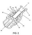
- FIG. 2illustrates a cross section view of one embodiment of a needle-free valve in the second position.
- FIG. 2provides a representative embodiment of the internal layout of the needle-free valve.
- the layout of the devicemay have differing shapes, sizes, O-rings and diaphragms.
- FIG. 3illustrates a perspective view of one embodiment of a needle-free valve in the first position. Additional representative embodiments in the first position may have differing shapes and sizes. Additional embodiments also may conform to the first position and results in a differing shape and size of the device in the first position.
- FIG. 4illustrates a cross-section view of one embodiment of a needle-free valve in the first position. Additional representative embodiments in the first position may have differing shapes, sizes O-rings and diaphragms. Additional embodiments also may conform to the first position and results in a differing interfaces between the O-rings and diaphragms of the device.
- FIG. 5illustrates a side view one embodiment of a needle-free valve in the first position that incorporates aspects of the present invention. Additional representative embodiments in the first position may have differing shapes and sizes. Additional embodiments also may conform to the first position and results in a differing shape and size of the device.
- FIG. 6illustrates a cross section of one embodiment of a needle-free valve in the second position outlining flow though the primary passageway. Additional representative embodiments in the second position may have differing shapes and sizes. Additional embodiments also may conform to the first position and result in a differing shape and size of the device in the second position.
- FIG. 7illustrates a cross-section view of one embodiment of a needle-free valve in the first position outlining flow through the secondary passageway. Additional representative embodiments in the first position may have differing shapes, sizes O-rings and diaphragms. Additional embodiments also may conform to the first position and results in a differing interfaces between the O-rings and diaphragms of the device.
- the needle free valvemay be embodied in different configurations and is not limited to any of those configurations disclosed.
- FIG. 1Illustrated in FIG. 1 is a side external view of an embodiments of a needle-free valve that includes various aspects of the present invention. Other embodiments may have differing shapes, sizes and points of connection.
- FIG. 1presents an embodiment of a needle-free valve 11 having luer feature 12 that is slidably dispose within a collar 13 .
- the luer featuredefines an inlet 17 with a lip 10 used for interfacing with medical devices not limited to syringes, bottle, tubing, ports and catheters.
- the luer feature 12may be a female port.
- the collar 13is slidably disposed around the luer feature 12 .
- the body 18may be formed from an upper body portion 14 , a middle body portion 15 and a lower body portion 16 .
- the lower body portion 16forms the outlet, that in this case may be a male port.
- Such a lower body portion 16may be have differing configurations and sizes.
- the lower body portion 16may also contain threads for attaching screw type devices as well as additional attachment devices (the threads are not visible in FIG. 1 ).
- the upper body portion 14 , middle body portion 15 and lower body portion 16may be made from the same or different materials and may be made from the same or different materials as the luer feature 12 or the collar 13 , both of which may be made of the same or different materials as each other and the other portions of the body.
- Representative materials from which the upper body portion 14 , middle body portion 15 , lower body portion 16 , luer feature 12 and collar 13 are madeinclude:
- the materials used to construct the abovecan be any of a number of commodity or engineering plastics (e.g. polyethylene, polycarbonate, polyamide, PVC, acrylic, polypropylene, PET, polytetrafluoroethylene (PTFE), glass-filled PTFE, ethylene polypropylene, flourosilicone, etc.) or metals (aluminum, titanium, stainless steel, etc.) used in similar medical device applications and products.
- commodity or engineering plasticse.g. polyethylene, polycarbonate, polyamide, PVC, acrylic, polypropylene, PET, polytetrafluoroethylene (PTFE), glass-filled PTFE, ethylene polypropylene, flourosilicone, etc.
- metalsaluminum, titanium, stainless steel, etc.
- FIG. 2is a cross-section view of an embodiment of a needle-free device with the collar 13 in the second position.
- the luer feature 12is set forth within the slidably disposed collar 13 .
- the inlet 17Within the center of the luer feature 12 is the inlet 17 .
- the inlet 17may be of various sizes that allow its connection with differing types of ports, bottles, bags, tubing and syringes.
- the inlet 17comprises a luer feature 12 and a diaphragm plunger 20 .
- the cylindrical diaphragm plunger 20is hollow and may extend the entire length or partial length of the inlet 17 and may or may not contain a vent. The disclosure of the plunger 20 in FIG.
- the diaphragm plunger 20may be of various diameters and lengths and may be made of the same or different materials as the additional parts of the device.
- the collar 13is slidably displaced about the luer 12 and may possess one or more O-rings 19 that provide a sealing interface between the collar 13 and the luer 12 .
- the O-rings 19may also form a sealing interface between the collar 13 and the upper body portion 14 .
- the O-ringsare preferably made of any number of elastomers or rubbers (e.g. Buna-N, Viton, Silicone, Neoprene, etc,).
- a primary O-ring 30may form a sealing interface between the collar 13 and the luer 17 while the secondary O-ring 31 does not form a sealing interface between the collar and the upper body portion 14 , thus allowing passage of fluid through the device.
- a primary O-ring 39forms a sealing interface between the collar 13 and the luer 17 while the secondary O-ring 31 forms a sealing interface between the collar and the upper body portion 14 , thus preventing the passage of gas or fluid through the device.
- the diaphragm plungerextends beyond the base of the luer 12 and through the upper body portion 14 and the middle body portion 15 .
- the diaphragm plungermay be slidably disposed within the luer 12 , the upper body portion 14 and the lower body portion 16 .
- the base of the diaphragm plunger 20rests on the diaphragm 23 that extends outward beyond the diameter of the diaphragm plunger.
- the diaphragm 23is circular in certain embodiments, but may also be formed in other shapes as necessary to function appropriately.
- the diaphragm 23rests against the portion of the middle body portion 15 closest to the lower body portion 16 .
- the diaphragmdoes not extend to the outer edge of the middle portion of the body in order to allow the secondary passageway 27 to remain in the open position. In other embodiments, however, the diaphragm 23 may extend to the outer edge of the middle portion 15 of the body.
- the diaphragm 23is supported by diaphragm support 32 which is preferably angled as shown in FIG. 2 .
- the diaphragmis preferably made from an elastomer or rubber (e.g. silicone). These materials in no way limit the type of material that may form the diaphragm.
- the diaphragm support 32is formed by a portion of the lower body portion 16 that traverses the outlet 24 .
- the lower body portion 16is circular in nature and contains an outer ring and inner male port.
- the inner male portforms the fluid outlet of the valve.
- the outer ring of the lower body portion 16may contain threads to assist in interfacing with devices that may connect to the male port.
- the middle body portion the embodiment shown in FIG. 2contains a fluid bypass 18 that runs perpendicular to the plane of the middle body portion 15 .
- This fluid bypass 18allows flow from the upper body portion 14 through middle body portion 15 to the lower body portion 16 and vice versa.
- the fluid bypass 18may possess differing configurations in order to form a bypass.
- the fluid bypass 18may be located at the outer edge of the diaphragm 23 and is in the form of hollow tubes traversing the plane of the of the middle body portion 15 .
- the fluid bypass 18may be of any shape and size to permit fluid passage.
- FIG. 3is a perspective view of a needle-free device embodiment of the present invention with the collar 13 in the first position.
- the collar 13When the collar 13 is in the first position, the collar 13 is extended toward the luer feature 12 away from the upper body portion 14 .
- FIG. 3also provides a view of the fluid outlet 24 wherein the male port is centered.
- FIG. 3is representative of a normally open state of the device. In this position, the valve may be sterilized allowing fluid sterilization agents to contact the surfaces of the valve. While the embodiment represented by this FIG. 3 does not contain threads on any portion of the male port, other embodiments may possess threads on the male port.
- FIG. 4is a cross section view of an embodiment of the needle free valve with the collar 13 in the first position.
- a fluid bypass exhaust 25exists at the opening between the collar 13 and the upper body portion 14 .
- the size of the fluid bypass exhaust 25may vary depending of the type of exhaust that requires venting.
- an embodiment of the inventionmay posses a primary O-ring 30 that interfaces the collar while the secondary O-ring 31 does not interface with the upper body portion 14 .
- Such an embodimentdiffers from an embodiment in the second position where the secondary O-ring 31 would interface with the upper body portion 14 .
- the primary O-ring 31may form a seal at its interface with the collar 13 thereby forming a fluid bypass exhaust 25 in the device.
- FIG. 5is a side view of an embodiment of a needle-free device with the collar 13 in the first position extended toward the luer feature 12 away from the upper body portion 14 .
- FIG. 5demonstrates that the collar 13 may extend beyond the luer feature 12 in the first position.
- the view of the fluid bypass 27is also shown and may extend around the circumference of the upper body portion 14 .
- Other embodimentsmay provide for differing vents for the fluid bypass 27 .
- FIG. 6provides a cross-section view of an embodiment of a needle-free valve with the collar in the first position demonstrating flow through the primary passageway 28 .
- This figureis an example of an embodiment demonstrating that when a syringe or device is connected at the luer, the collar 13 will be in the first position to seal the-off the fluid bypass exhaust 25 .
- FIG. 6also provides an embodiment demonstrating a configuration that may exist when the valve is depressed by a syringe, port or tubing is attached to the luer 12 that would depress the plunger 17 and deflect a diaphragm 23 . Such a configuration allows flow around the diaphragm 23 and through the device and through the primary passageway 28 .
- flow through the primary passagewayoccurs when fluid enters the inlet 17 at the luer traveling through the hollow diaphragm plunger 20 and then through a vent 20 on the diaphragm plunger 29 that may extend from the base of the diaphragm plunger 20 to the upper body portion 14 .
- the vent 29forms a passage that is bounded by the diaphragm plunger 23 , middle body portion 15 and diaphragm 23 .
- the flowis contained in volume defined by the middle body portion 15 and lower body portion 16 . Flow may then travel through the top portion of the outlet in the lower body portion 16 and finally through the outlet 24 on the male port of the lower body portion 16 .
- FIG. 7provides an embodiment disclosing a cross section view of a needle-free valve with the collar 13 in the second position demonstrating flow through the secondary passageway 27 when the primary passageway 28 is closed.
- This figuredemonstrates that when a syringe or device is not connected at the luer, the collar 13 will be in the second position opening the fluid bypass exhaust 25 . In this position, a syringe or device may not be attached at the luer 12 and as a result, the diaphragm plunger 20 may not be depressed resulting the primary passageway 28 being closed.
- flow through the secondary passagewayoccurs first by entering the fluid bypass 18 then traveling through the inside of the collar 13 on the upper body portion 14 that extends around the circumference of the lower body portion 16 of the needle free valve.
- flowthen proceeds through individual passageways that extend through the upper body portion 14 into a chamber formed by the upper body portion 14 and middle body portion 15 .
- Flow from this chamberthen proceeds through the a passageway formed by the middle body portion 15 into a volume defined by the middle body portion 15 and lower body portion 16 .
- Flowmay then travel through the top portion of the outlet in the lower body portion 16 and finally through the outlet 24 on the male port of the lower body portion 16 .
- Flowmay also proceed in the opposite direction. This description of flow is not meant to limit the direction or type of flow through the device.
- Additional embodiments of this inventionmay be defined as a valve fittings that may possess a valve assembly having a valve body 18 .
- the valve body 18comprises a first end and a second end and also comprise a primary passageway 28 and a secondary passageway 27 between the first and second ends.
- the embodiments of this inventionalso may possess a diaphragm 23 within the primary passageway 28 .
- the diaphragm 23may be in an open position or a closed position. When the diaphragm 23 is in the open position, the primary passageway 28 is open and secondary passageway 27 is closed. However, when the diaphragm is in the closed position, the primary passageway 28 is closed and the secondary passageway 27 may be open depending on whether the collar 13 is in a first or second position.
- embodiments of this inventionalso possess a collar 13 slidably disposed around the first end. When the collar is in a first position the secondary passageway is open, and when the collar is in a second position the secondary passageway is closed.
- the needle free valve fittingmay comprise a valve assembly with a valve body 18 .
- the valve body 18 in this embodimentmay possess an inlet 17 , a plunger 20 , and an outlet 24 .
- the valve body 18also defines a primary passageway 28 and secondary passageway 27 between the inlet 17 and outlet 24 .
- This embodimentalso may possess a plunger 20 that is moveable within the inlet 17 .
- Such embodimentsalso may possess a diaphragm 23 within the primary passageway 28 between the inlet 17 and outlet 24 .
- the diaphragm 23opens in response to movement of the plunger 20 , and when the diaphragm 23 is open, the primary passageway 28 is open and the secondary passageway 27 is closed.
- the primary passageway 28is closed and the secondary passageway 27 may be open depending on whether a collar 13 is in the a first or second position.
- the collarmay possess O-ring seals 19 at the interface of the body and collar. Additionally, certain embodiments contain a diaphragm that may be positioned between the plunger and a diaphragm support 32 . In these embodiments, the plunger may contain a vent 30 as shown in FIG. 6 . Theses embodiments also have a first end that comprises a luer for device attachment.
- An additional embodiment of the inventionincludes a method of sterilizing a device in a manner where differential pressure will not exist between the inlet 17 and outlet 24 of the device.
- This methodincludes providing a needle free valve fitting that has a valve assembly with a valve body 18 .
- the valve bodycomprising an inlet 17 , a plunger 20 that moves in within the inlet 17 , and an outlet 24 .
- the valve body 18defines a primary passageway 28 and secondary passageway 27 between the inlet 17 and outlet 24 .
- the needle free valve fitting used in the methodmay also possesses a diaphragm 23 in the primary passageway 28 between the inlet 17 and outlet 24 where the diaphragm 23 opens in response to movement by the plunger 20 .
- Movement of the plunger 20may open or close the diaphragm 23 so that when the diaphragm is open, the primary passageway 28 is open and the secondary passageway 27 is closed.
- the primary passageway 28is closed and the secondary passageway 27 may be open depending on whether the collar 13 in the first or second position.
- the active step in the methodwould consist of exposing the needle free valve fitting to a fluid sterilization agent that will be in communication with surface areas such as the body 18 , the inlet 17 and outlet 24 , the plunger 20 , the primary passageway 28 and secondary passageway 27 , the diaphragm 23 and collar 13 .
- a fluid sterilization agentthat will be in communication with surface areas such as the body 18 , the inlet 17 and outlet 24 , the plunger 20 , the primary passageway 28 and secondary passageway 27 , the diaphragm 23 and collar 13 .
- the diaphragm 23may be open or closed and the collar 13 may be in a first or second position.
- the fluid sterilization agentmay be ethylene oxide as encompassed by embodiments of the claimed invention.
- additional means of gas sterilizationuse plasma/hydrogen peroxide gas, ozone and chlorine dioxide.
- other methods of sterilizationinclude radiation and e-beam processes, pulsed UV light, x-ray and gamma irradiation, electron beam, steam and heat processes, autoclaves and dry heat. Each of which may be combined or performed separately.
- ethylene oxideis the state of the art in sterilization in the device field.
- the relatively low process temperaturein comparison to steam sterilization has made ethylene oxide sterilization an excellent method for many products.
- ethylene oxidemakes it an ideal sterilizing agent. This property, however, also makes it extremely dangerous at ambient oxygen levels.
- a set of evacuations coupled with steam additionsis executed at the start of every sterilization procedure. Ethylene oxide gas is then added and allowed to sit with the product being sterilized. During this point in the method, the ethylene oxide comes in contact with all of the surface areas of the valve fitting.
- this “sitting phase” or “gas dwell phase”the product and its packaging absorb ethylene oxide gas. Following the gas dwell phase, a series of evacuations and air infusions occur. This helps in the removal of gas from the product.
- the productis then transferred to an aeration chamber where ethylene oxide and ethylene oxide degradation products dissipate safely from the product.
- this gas dissipation periodmay last from several hours to weeks and even months.
- the gasis evacuated from the chamber and the product is removed.
Landscapes
- Health & Medical Sciences (AREA)
- Heart & Thoracic Surgery (AREA)
- Biomedical Technology (AREA)
- Pulmonology (AREA)
- Engineering & Computer Science (AREA)
- Anesthesiology (AREA)
- Epidemiology (AREA)
- Hematology (AREA)
- Life Sciences & Earth Sciences (AREA)
- Animal Behavior & Ethology (AREA)
- General Health & Medical Sciences (AREA)
- Public Health (AREA)
- Veterinary Medicine (AREA)
- Infusion, Injection, And Reservoir Apparatuses (AREA)
Abstract
Description
Claims (18)
Priority Applications (2)
| Application Number | Priority Date | Filing Date | Title |
|---|---|---|---|
| US12/371,346US8523826B2 (en) | 2009-02-13 | 2009-02-13 | Luer-type needle-free valve fitting with bypass |
| PCT/US2010/024118WO2010093936A1 (en) | 2009-02-13 | 2010-02-12 | Luer-type needle-free valve fitting with bypass |
Applications Claiming Priority (1)
| Application Number | Priority Date | Filing Date | Title |
|---|---|---|---|
| US12/371,346US8523826B2 (en) | 2009-02-13 | 2009-02-13 | Luer-type needle-free valve fitting with bypass |
Publications (2)
| Publication Number | Publication Date |
|---|---|
| US20100211020A1 US20100211020A1 (en) | 2010-08-19 |
| US8523826B2true US8523826B2 (en) | 2013-09-03 |
Family
ID=42560561
Family Applications (1)
| Application Number | Title | Priority Date | Filing Date |
|---|---|---|---|
| US12/371,346Expired - Fee RelatedUS8523826B2 (en) | 2009-02-13 | 2009-02-13 | Luer-type needle-free valve fitting with bypass |
Country Status (2)
| Country | Link |
|---|---|
| US (1) | US8523826B2 (en) |
| WO (1) | WO2010093936A1 (en) |
Cited By (23)
| Publication number | Priority date | Publication date | Assignee | Title |
|---|---|---|---|---|
| US8973596B2 (en) | 2012-07-12 | 2015-03-10 | Confluent Surgical, Inc. | Applicator assembly with integral check-valve |
| US20170020428A1 (en)* | 2015-07-24 | 2017-01-26 | Calliope Solutions, Inc. | Blood sample optimization system and blood contaminant sequestration device and method |
| US20180116577A1 (en)* | 2012-05-30 | 2018-05-03 | Magnolia Medical Technologies, Inc. | Fluid diversion mechanism for bodily-fluid sampling |
| US20180271425A1 (en)* | 2017-02-10 | 2018-09-27 | Kurin, Inc. | Blood contaminant sequestration device with one-way air valve and air-permeable blood barrier with closure mechanism |
| USD843567S1 (en)* | 2016-11-07 | 2019-03-19 | Ide Tecnologia S.A De C.V. | Dialysis device connector without threads |
| USD845474S1 (en)* | 2016-11-07 | 2019-04-09 | Ide Tecnologia S.A. De C.V. | Dialysis device connector |
| USD849938S1 (en)* | 2016-11-07 | 2019-05-28 | Ide Tecnologia S.A. De C.V. | Dialysis device connector |
| USD851243S1 (en)* | 2016-11-07 | 2019-06-11 | Ide Technologies S.A. De C.V. | Dialysis device connector with threads |
| US20200281514A1 (en)* | 2017-02-10 | 2020-09-10 | Kurin, Inc. | Blood contaminant sequestration device with passive fluid control junction |
| US10772548B2 (en) | 2012-12-04 | 2020-09-15 | Magnolia Medical Technologies, Inc. | Sterile bodily-fluid collection device and methods |
| US10881343B2 (en) | 2012-08-01 | 2021-01-05 | Magnolia Medical Technologies, Inc. | Fluid diversion mechanism for bodily-fluid sampling |
| US11076787B2 (en) | 2017-09-12 | 2021-08-03 | Magnolia Medical Technologies, Inc. | Fluid control devices and methods of using the same |
| US11234626B2 (en) | 2015-06-12 | 2022-02-01 | Magnolia Medical Technologies, Inc. | Devices and methods for syringe-based fluid transfer for bodily-fluid sampling |
| US11259727B2 (en) | 2012-12-04 | 2022-03-01 | Magnolia Medical Technologies, Inc. | Sterile bodily-fluid collection device and methods |
| US11311218B2 (en) | 2012-11-30 | 2022-04-26 | Magnolia Medical Technologies, Inc. | Syringe-based fluid diversion mechanism for bodily fluid sampling |
| US11311219B2 (en) | 2016-12-27 | 2022-04-26 | Kurin, Inc. | Blood sample optimization system and blood contaminant sequestration device and method |
| US11395612B2 (en)* | 2012-05-30 | 2022-07-26 | Magnolia Medical Technologies, Inc. | Fluid diversion mechanism for bodily-fluid sampling |
| US11419531B2 (en) | 2017-12-07 | 2022-08-23 | Magnolia Medical Technologies, Inc. | Fluid control devices and methods of using the same |
| US11786155B2 (en) | 2019-02-08 | 2023-10-17 | Magnolia Medical Technologies, Inc. | Devices and methods for bodily fluid collection and distribution |
| US11857321B2 (en) | 2019-03-11 | 2024-01-02 | Magnolia Medical Technologies, Inc. | Fluid control devices and methods of using the same |
| US11890452B2 (en) | 2012-10-11 | 2024-02-06 | Magnolia Medical Technologies, Inc. | Systems and methods for delivering a fluid to a patient with reduced contamination |
| US12083234B2 (en) | 2015-09-03 | 2024-09-10 | Magnolia Medical Technologies, Inc. | Apparatus and methods for maintaining sterility of a specimen container |
| US12383174B2 (en) | 2019-04-01 | 2025-08-12 | Kurin, Inc. | Non-venting bodily fluid sample optimization device and system |
Families Citing this family (7)
| Publication number | Priority date | Publication date | Assignee | Title |
|---|---|---|---|---|
| WO2010109449A1 (en) | 2009-03-22 | 2010-09-30 | Elcam Medical Agricultural Cooperative Association Ltd. | Closed male luer connector |
| EP2282070B1 (en)* | 2009-08-06 | 2012-10-17 | ECP Entwicklungsgesellschaft mbH | Catheter device with a coupling device for a drive device |
| KR101802912B1 (en)* | 2009-10-09 | 2017-11-29 | 다니엘 파이 | Device with co-molded closure, one-way valve and variable-volume storage chamber, and related method |
| DE202012007884U1 (en)* | 2012-08-20 | 2012-09-07 | Illinois Tool Works Inc. | One-way valve means |
| DE102012022359A1 (en)* | 2012-11-15 | 2014-05-15 | Vetter Pharma-Fertigung GmbH & Co. KG | Attachment for a syringe or carpule |
| AU201814813S (en)* | 2018-02-14 | 2018-10-03 | Emtbio Co | Adapter for vial |
| US11147959B1 (en)* | 2021-03-31 | 2021-10-19 | Jason Lakis | Syringe apparatus for disinfection of central line port needleless connector and method of disinfecting a central line port needleless connector |
Citations (35)
| Publication number | Priority date | Publication date | Assignee | Title |
|---|---|---|---|---|
| US3192949A (en) | 1962-07-10 | 1965-07-06 | Halkey Roberts Corp | Spring biased check valve |
| US3385301A (en) | 1965-10-11 | 1968-05-28 | American Hospital Supply Corp | Balloon catheter having a deformable one-way inflation valve |
| US3570484A (en) | 1967-08-31 | 1971-03-16 | Eschmann Bros & Walsh Ltd | Intravenous valve assembly |
| US3831629A (en) | 1972-01-24 | 1974-08-27 | Halkey Roberts Corp | Check valve |
| US3896853A (en)* | 1972-07-10 | 1975-07-29 | Pro Medical Eng Ab | Coupling means for use with blood sampling apparatus |
| US3986508A (en)* | 1973-08-22 | 1976-10-19 | Abcor, Inc. | Sterilizable, medical connector for blood processing |
| US4160383A (en)* | 1977-12-27 | 1979-07-10 | Will Ross Inc. | Unitary sample-vent-valve assembly |
| US4222407A (en) | 1978-09-13 | 1980-09-16 | Baxter Travenol Laboratories, Inc. | One-way flex valve |
| US4246932A (en) | 1979-10-18 | 1981-01-27 | Burron Medical, Inc. | Multiple additive valve assembly |
| US4286628A (en) | 1979-06-21 | 1981-09-01 | Nypro, Inc. | Control of fluid flow using longitudinally movable disc |
| US4310017A (en) | 1980-01-30 | 1982-01-12 | Burron Medical Inc. | Backflow check valve for use with IV administration sets |
| US4369812A (en) | 1981-02-18 | 1983-01-25 | Nypro Inc. | Control of fluid flow using precisely positioned disc |
| US4535820A (en)* | 1984-05-24 | 1985-08-20 | Burron Medical Inc. | Normally closed check valve |
| US4683916A (en)* | 1986-09-25 | 1987-08-04 | Burron Medical Inc. | Normally closed automatic reflux valve |
| US4725266A (en)* | 1985-03-25 | 1988-02-16 | Siposs George G | Left ventricle vacuum control and pressure relief valve |
| US4878513A (en)* | 1988-09-28 | 1989-11-07 | Gt Development Corporation | Quick vent valve for air brake line |
| US4935010A (en)* | 1986-11-20 | 1990-06-19 | Pharmacia Limited | Devices for sampling, drainage or infusion of liquids from or to the human or animal body |
| US5242411A (en)* | 1991-01-18 | 1993-09-07 | Terumo Kabushiki Kaisha | Piercing needle having hydrophobic filter vent |
| US5423791A (en) | 1992-03-31 | 1995-06-13 | Bartlett; J. Mark | Valve device for medical fluid transfer |
| US6039302A (en)* | 1996-11-18 | 2000-03-21 | Nypro Inc. | Swabbable luer-activated valve |
| US6482188B1 (en) | 1999-10-01 | 2002-11-19 | Mission Medical Devices, Inc. | Nonvented needle-free injection valve |
| US20040073171A1 (en) | 2002-10-10 | 2004-04-15 | Rogers Bobby E. | Needle-free valve and catheter assembly |
| US20040124389A1 (en)* | 2002-12-31 | 2004-07-01 | Phillips John C. | Self-sealing male luer connector with biased valve plug |
| US20040158211A1 (en) | 2003-02-07 | 2004-08-12 | Rogers Bobby E. | Closed system catheterization assembly and related methods |
| US6875205B2 (en) | 2002-02-08 | 2005-04-05 | Alaris Medical Systems, Inc. | Vial adapter having a needle-free valve for use with vial closures of different sizes |
| US20050194047A1 (en)* | 2004-03-05 | 2005-09-08 | Liebel-Flarsheim Company | Check valve for a fluid administration system |
| US20060192164A1 (en) | 2005-02-14 | 2006-08-31 | Korogi Todd M | Valved fluid connector |
| US20060253090A1 (en) | 2005-05-04 | 2006-11-09 | Bradley Arthur J | Method and apparatus for facilitating evacuation and cleansing of a colonostomy bag |
| US20060276770A1 (en) | 2005-05-13 | 2006-12-07 | Bob Rogers | Medical substance transfer system |
| US20070083162A1 (en) | 2005-10-11 | 2007-04-12 | Span-America Medical Systems, Inc. | Valve for intravenous catheter |
| US20070156112A1 (en) | 2005-12-30 | 2007-07-05 | Walsh Mary K | Medical vial adapter with reduced diameter cannula and enlarged vent lumen |
| US20070260104A1 (en) | 2006-05-08 | 2007-11-08 | Bretz Phillip | Autologous fat pad transfer for use with partial breast irradiation |
| US7306199B2 (en) | 2001-11-29 | 2007-12-11 | Cardinal Health 303, Inc. | Needle free medical connector with expanded valve mechanism and method of fluid flow control |
| US7319735B2 (en) | 2001-10-19 | 2008-01-15 | Hologic, Inc. | Mammography system and method employing offset compression paddles, automatic collimation, and retractable anti-scatter grid |
| US7785299B2 (en)* | 2006-05-08 | 2010-08-31 | Becton, Dickinson And Company | Vascular access device time sensitive status indication |
- 2009
- 2009-02-13USUS12/371,346patent/US8523826B2/ennot_activeExpired - Fee Related
- 2010
- 2010-02-12WOPCT/US2010/024118patent/WO2010093936A1/enactiveApplication Filing
Patent Citations (38)
| Publication number | Priority date | Publication date | Assignee | Title |
|---|---|---|---|---|
| US3192949A (en) | 1962-07-10 | 1965-07-06 | Halkey Roberts Corp | Spring biased check valve |
| US3385301A (en) | 1965-10-11 | 1968-05-28 | American Hospital Supply Corp | Balloon catheter having a deformable one-way inflation valve |
| US3570484A (en) | 1967-08-31 | 1971-03-16 | Eschmann Bros & Walsh Ltd | Intravenous valve assembly |
| US3831629A (en) | 1972-01-24 | 1974-08-27 | Halkey Roberts Corp | Check valve |
| US3896853A (en)* | 1972-07-10 | 1975-07-29 | Pro Medical Eng Ab | Coupling means for use with blood sampling apparatus |
| US3986508A (en)* | 1973-08-22 | 1976-10-19 | Abcor, Inc. | Sterilizable, medical connector for blood processing |
| US4160383A (en)* | 1977-12-27 | 1979-07-10 | Will Ross Inc. | Unitary sample-vent-valve assembly |
| US4222407A (en) | 1978-09-13 | 1980-09-16 | Baxter Travenol Laboratories, Inc. | One-way flex valve |
| US4286628A (en) | 1979-06-21 | 1981-09-01 | Nypro, Inc. | Control of fluid flow using longitudinally movable disc |
| US4246932A (en) | 1979-10-18 | 1981-01-27 | Burron Medical, Inc. | Multiple additive valve assembly |
| US4310017A (en) | 1980-01-30 | 1982-01-12 | Burron Medical Inc. | Backflow check valve for use with IV administration sets |
| US4369812A (en) | 1981-02-18 | 1983-01-25 | Nypro Inc. | Control of fluid flow using precisely positioned disc |
| US4535820A (en)* | 1984-05-24 | 1985-08-20 | Burron Medical Inc. | Normally closed check valve |
| US4725266A (en)* | 1985-03-25 | 1988-02-16 | Siposs George G | Left ventricle vacuum control and pressure relief valve |
| US4683916A (en)* | 1986-09-25 | 1987-08-04 | Burron Medical Inc. | Normally closed automatic reflux valve |
| US4935010A (en)* | 1986-11-20 | 1990-06-19 | Pharmacia Limited | Devices for sampling, drainage or infusion of liquids from or to the human or animal body |
| US4878513A (en)* | 1988-09-28 | 1989-11-07 | Gt Development Corporation | Quick vent valve for air brake line |
| US5242411A (en)* | 1991-01-18 | 1993-09-07 | Terumo Kabushiki Kaisha | Piercing needle having hydrophobic filter vent |
| US5423791A (en) | 1992-03-31 | 1995-06-13 | Bartlett; J. Mark | Valve device for medical fluid transfer |
| US6039302A (en)* | 1996-11-18 | 2000-03-21 | Nypro Inc. | Swabbable luer-activated valve |
| US6482188B1 (en) | 1999-10-01 | 2002-11-19 | Mission Medical Devices, Inc. | Nonvented needle-free injection valve |
| US7319735B2 (en) | 2001-10-19 | 2008-01-15 | Hologic, Inc. | Mammography system and method employing offset compression paddles, automatic collimation, and retractable anti-scatter grid |
| US7306199B2 (en) | 2001-11-29 | 2007-12-11 | Cardinal Health 303, Inc. | Needle free medical connector with expanded valve mechanism and method of fluid flow control |
| US6875205B2 (en) | 2002-02-08 | 2005-04-05 | Alaris Medical Systems, Inc. | Vial adapter having a needle-free valve for use with vial closures of different sizes |
| US20050148994A1 (en) | 2002-02-08 | 2005-07-07 | Leinsing Karl R. | Vial adapter having a needle-free valve for use with vial closures of different sizes |
| US20040073171A1 (en) | 2002-10-10 | 2004-04-15 | Rogers Bobby E. | Needle-free valve and catheter assembly |
| US20040124389A1 (en)* | 2002-12-31 | 2004-07-01 | Phillips John C. | Self-sealing male luer connector with biased valve plug |
| US6979323B2 (en) | 2003-02-07 | 2005-12-27 | Aragon Medical Corporation | Closed system catheterization assembly and related methods |
| US20060155258A1 (en) | 2003-02-07 | 2006-07-13 | Aragon Medical Corporation | Closed system catheterization assembly and related methods |
| US20040158211A1 (en) | 2003-02-07 | 2004-08-12 | Rogers Bobby E. | Closed system catheterization assembly and related methods |
| US20050194047A1 (en)* | 2004-03-05 | 2005-09-08 | Liebel-Flarsheim Company | Check valve for a fluid administration system |
| US20060192164A1 (en) | 2005-02-14 | 2006-08-31 | Korogi Todd M | Valved fluid connector |
| US20060253090A1 (en) | 2005-05-04 | 2006-11-09 | Bradley Arthur J | Method and apparatus for facilitating evacuation and cleansing of a colonostomy bag |
| US20060276770A1 (en) | 2005-05-13 | 2006-12-07 | Bob Rogers | Medical substance transfer system |
| US20070083162A1 (en) | 2005-10-11 | 2007-04-12 | Span-America Medical Systems, Inc. | Valve for intravenous catheter |
| US20070156112A1 (en) | 2005-12-30 | 2007-07-05 | Walsh Mary K | Medical vial adapter with reduced diameter cannula and enlarged vent lumen |
| US20070260104A1 (en) | 2006-05-08 | 2007-11-08 | Bretz Phillip | Autologous fat pad transfer for use with partial breast irradiation |
| US7785299B2 (en)* | 2006-05-08 | 2010-08-31 | Becton, Dickinson And Company | Vascular access device time sensitive status indication |
Non-Patent Citations (8)
| Title |
|---|
| "About Brachytherapy: What is Brachytherapy", American Brachytherapy Society, Accessed May 28, 2008. |
| "Brachytherapy", Radiology Info, Accessed May 28, 2008. |
| "Brachytherapy", Wikipedia the free enclyclopedia, Accessed May 28, 2008. |
| "ETO Sterilization", Medical Device Link, Accessed Nov. 8, 2007. |
| "Keeping I.V. therapy safe with needless systems", Nursing, Accessed Jun. 24, 2008. |
| "Overview of Sterilization Procedures", Medical Device Link, Accessed Dec. 22, 2008. |
| DuPONT Medical Packaging Technical Reference Guide, (Jan. 2007). |
| Material Comparison Chart, Date unknown. |
Cited By (65)
| Publication number | Priority date | Publication date | Assignee | Title |
|---|---|---|---|---|
| US20230172502A1 (en)* | 2012-05-30 | 2023-06-08 | Magnolia Medical Technologies, Inc. | Fluid diversion mechanism for bodily-fluid sampling |
| US11395611B2 (en)* | 2012-05-30 | 2022-07-26 | Magnolia Medical Technologies, Inc. | Fluid diversion mechanism for bodily-fluid sampling |
| US12186080B2 (en) | 2012-05-30 | 2025-01-07 | Magnolia Medical Technologies, Inc. | Fluid diversion mechanism for bodily-fluid sampling |
| US10912506B2 (en) | 2012-05-30 | 2021-02-09 | Magnolia Medical Technologies, Inc. | Fluid diversion mechanism for bodily-fluid sampling |
| US20180116577A1 (en)* | 2012-05-30 | 2018-05-03 | Magnolia Medical Technologies, Inc. | Fluid diversion mechanism for bodily-fluid sampling |
| US11998332B2 (en)* | 2012-05-30 | 2024-06-04 | Magnolia Medical Technologies, Inc. | Fluid diversion mechanism for bodily-fluid sampling |
| US12193816B2 (en) | 2012-05-30 | 2025-01-14 | Magnolia Medical Technologies, Inc. | Fluid diversion mechanism for bodily-fluid sampling |
| US11819329B2 (en) | 2012-05-30 | 2023-11-21 | Magnolia Medical Technologies, Inc. | Fluid diversion mechanism for bodily-fluid sampling |
| US20240041369A1 (en)* | 2012-05-30 | 2024-02-08 | Magnolia Medical Technologies, Inc. | Fluid diversion mechanism for bodily-fluid sampling |
| US11395612B2 (en)* | 2012-05-30 | 2022-07-26 | Magnolia Medical Technologies, Inc. | Fluid diversion mechanism for bodily-fluid sampling |
| US10736554B2 (en)* | 2012-05-30 | 2020-08-11 | Magnolia Medical Technologies, Inc. | Fluid diversion mechanism for bodily-fluid sampling |
| US8973596B2 (en) | 2012-07-12 | 2015-03-10 | Confluent Surgical, Inc. | Applicator assembly with integral check-valve |
| US10881343B2 (en) | 2012-08-01 | 2021-01-05 | Magnolia Medical Technologies, Inc. | Fluid diversion mechanism for bodily-fluid sampling |
| US11890452B2 (en) | 2012-10-11 | 2024-02-06 | Magnolia Medical Technologies, Inc. | Systems and methods for delivering a fluid to a patient with reduced contamination |
| US12133968B2 (en) | 2012-10-11 | 2024-11-05 | Magnolia Medical Technologies, Inc. | Systems and methods for delivering a fluid to a patient with reduced contamination |
| US11607159B2 (en) | 2012-11-30 | 2023-03-21 | Magnolia Medical Technologies, Inc. | Bodily-fluid transfer system for bodily fluid sampling |
| US11317838B2 (en) | 2012-11-30 | 2022-05-03 | Magnolia Medical Technologies, Inc. | Syringe-based fluid diversion mechanism for bodily fluid sampling |
| US11660030B2 (en) | 2012-11-30 | 2023-05-30 | Magnolia Medical Technologies, Inc. | Syringe-based fluid diversion mechanism for bodily fluid sampling |
| US11589786B2 (en) | 2012-11-30 | 2023-02-28 | Magnolia Medical Technologies, Inc. | Syringe-based fluid diversion mechanism for bodily fluid sampling |
| US11311218B2 (en) | 2012-11-30 | 2022-04-26 | Magnolia Medical Technologies, Inc. | Syringe-based fluid diversion mechanism for bodily fluid sampling |
| US10772548B2 (en) | 2012-12-04 | 2020-09-15 | Magnolia Medical Technologies, Inc. | Sterile bodily-fluid collection device and methods |
| US11737693B2 (en) | 2012-12-04 | 2023-08-29 | Magnolia Medical Technologies, Inc. | Sterile bodily-fluid collection device and methods |
| US11259727B2 (en) | 2012-12-04 | 2022-03-01 | Magnolia Medical Technologies, Inc. | Sterile bodily-fluid collection device and methods |
| US12150763B2 (en) | 2012-12-04 | 2024-11-26 | Magnolia Medical Technologies, Inc. | Sterile bodily-fluid collection device and methods |
| US11234626B2 (en) | 2015-06-12 | 2022-02-01 | Magnolia Medical Technologies, Inc. | Devices and methods for syringe-based fluid transfer for bodily-fluid sampling |
| US20170020427A1 (en)* | 2015-07-24 | 2017-01-26 | Calliope Solutions, Inc. | Blood sample optimization system and blood contaminant sequestration device and method |
| US12390137B2 (en)* | 2015-07-24 | 2025-08-19 | Kurin, Inc. | Blood sample optimization device |
| US20170020428A1 (en)* | 2015-07-24 | 2017-01-26 | Calliope Solutions, Inc. | Blood sample optimization system and blood contaminant sequestration device and method |
| US11832944B2 (en)* | 2015-07-24 | 2023-12-05 | Kurin, Inc. | Blood sample optimization device |
| US20220079483A1 (en)* | 2015-07-24 | 2022-03-17 | Kurin, Inc. | Blood sample optimization system and blood contaminant sequestration device and method |
| US20240374186A1 (en)* | 2015-07-24 | 2024-11-14 | Kurin, Inc. | Blood sample optimization device |
| US11185266B2 (en)* | 2015-07-24 | 2021-11-30 | Kurin, Inc. | Blood sample optimization system and blood contaminant sequestration device and method |
| US12138052B1 (en)* | 2015-07-24 | 2024-11-12 | Kurin, Inc. | Blood sample optimization device |
| US9820682B2 (en)* | 2015-07-24 | 2017-11-21 | Kurin, Inc. | Blood sample optimization system and blood contaminant sequestration device and method |
| US10143412B2 (en) | 2015-07-24 | 2018-12-04 | Kurin, Inc. | Blood sample optimization system and blood contaminant sequestration device and method |
| US12357209B2 (en)* | 2015-07-24 | 2025-07-15 | Kurin, Inc. | Blood sample optimization device |
| US20240252079A1 (en)* | 2015-07-24 | 2024-08-01 | Kurin, Inc. | Blood sample optimization device |
| US20230210422A1 (en)* | 2015-07-24 | 2023-07-06 | Kurin, Inc. | Blood sample optimization system and blood contaminant sequestration device and method |
| US20250025079A1 (en)* | 2015-07-24 | 2025-01-23 | Kurin, Inc. | Blood sample optimization device |
| US10010282B2 (en)* | 2015-07-24 | 2018-07-03 | Kurin, Inc. | Blood sample optimization system and blood contaminant sequestration device and method |
| US11963769B2 (en)* | 2015-07-24 | 2024-04-23 | Kurin, Inc. | Blood sample optimization system and blood contaminant sequestration device and method |
| US12083234B2 (en) | 2015-09-03 | 2024-09-10 | Magnolia Medical Technologies, Inc. | Apparatus and methods for maintaining sterility of a specimen container |
| USD851243S1 (en)* | 2016-11-07 | 2019-06-11 | Ide Technologies S.A. De C.V. | Dialysis device connector with threads |
| USD845474S1 (en)* | 2016-11-07 | 2019-04-09 | Ide Tecnologia S.A. De C.V. | Dialysis device connector |
| USD843567S1 (en)* | 2016-11-07 | 2019-03-19 | Ide Tecnologia S.A De C.V. | Dialysis device connector without threads |
| USD849938S1 (en)* | 2016-11-07 | 2019-05-28 | Ide Tecnologia S.A. De C.V. | Dialysis device connector |
| US11311219B2 (en) | 2016-12-27 | 2022-04-26 | Kurin, Inc. | Blood sample optimization system and blood contaminant sequestration device and method |
| US11617525B2 (en)* | 2017-02-10 | 2023-04-04 | Kurin, Inc. | Blood contaminant sequestration device with passive fluid control junction |
| US10827964B2 (en)* | 2017-02-10 | 2020-11-10 | Kurin, Inc. | Blood contaminant sequestration device with one-way air valve and air-permeable blood barrier with closure mechanism |
| US20210145336A1 (en)* | 2017-02-10 | 2021-05-20 | Kurin, Inc. | Blood contaminant sequestration device with one-way air valve and air-permeable blood barrier with closure mechanism |
| US11744494B2 (en)* | 2017-02-10 | 2023-09-05 | Kurin, Inc. | Blood contaminant sequestration device with one-way air valve and air-permeable blood barrier with closure mechanism |
| US12257051B2 (en)* | 2017-02-10 | 2025-03-25 | Kurin, Inc. | Blood contaminant sequestration device with one-way air valve and air-permeable blood barrier with closure mechanism |
| US20240122510A1 (en)* | 2017-02-10 | 2024-04-18 | Kurin, Inc. | Blood contaminant sequestration device with one-way air valve and air-permeable blood barrier with closure mechanism |
| US20180271425A1 (en)* | 2017-02-10 | 2018-09-27 | Kurin, Inc. | Blood contaminant sequestration device with one-way air valve and air-permeable blood barrier with closure mechanism |
| US20200281514A1 (en)* | 2017-02-10 | 2020-09-10 | Kurin, Inc. | Blood contaminant sequestration device with passive fluid control junction |
| US11653863B2 (en) | 2017-09-12 | 2023-05-23 | Magnolia Medical Technologies, Inc. | Fluid control devices and methods of using the same |
| US11529081B2 (en) | 2017-09-12 | 2022-12-20 | Magnolia Medical Technologies, Inc. | Fluid control devices and methods of using the same |
| US11903710B2 (en) | 2017-09-12 | 2024-02-20 | Magnolia Medical Technologies, Inc. | Fluid control devices and methods of using the same |
| US11903709B2 (en) | 2017-09-12 | 2024-02-20 | Magnolia Medical Technologies, Inc. | Fluid control devices and methods of using the same |
| US12290363B2 (en) | 2017-09-12 | 2025-05-06 | Magnolia Medical Technologies, Inc. | Fluid control devices and methods of using the same |
| US11076787B2 (en) | 2017-09-12 | 2021-08-03 | Magnolia Medical Technologies, Inc. | Fluid control devices and methods of using the same |
| US11419531B2 (en) | 2017-12-07 | 2022-08-23 | Magnolia Medical Technologies, Inc. | Fluid control devices and methods of using the same |
| US11786155B2 (en) | 2019-02-08 | 2023-10-17 | Magnolia Medical Technologies, Inc. | Devices and methods for bodily fluid collection and distribution |
| US11857321B2 (en) | 2019-03-11 | 2024-01-02 | Magnolia Medical Technologies, Inc. | Fluid control devices and methods of using the same |
| US12383174B2 (en) | 2019-04-01 | 2025-08-12 | Kurin, Inc. | Non-venting bodily fluid sample optimization device and system |
Also Published As
| Publication number | Publication date |
|---|---|
| WO2010093936A1 (en) | 2010-08-19 |
| US20100211020A1 (en) | 2010-08-19 |
Similar Documents
| Publication | Publication Date | Title |
|---|---|---|
| US8523826B2 (en) | Luer-type needle-free valve fitting with bypass | |
| AU2015319732B2 (en) | Improved needle valve and connectors for use in liquid transfer apparatuses | |
| JP6355758B2 (en) | System having an adapter for closed transfer of fluid | |
| JP6073421B2 (en) | Closed fluid transfer system | |
| AU2019200796B2 (en) | System for Enhanced Sealing of Coupled Medical Fluid Lines and Method | |
| AU652873B2 (en) | Pre-filled plastic syringes and containers and method of terminal sterilization thereof | |
| JP5216846B2 (en) | Method and apparatus for transferring harmful drugs without contamination | |
| US10555872B1 (en) | Convenience kits for aseptic sterilizing and dispensing | |
| CN104334213A (en) | Multiple dose vials and methods | |
| EP1115362B1 (en) | Container for intravenous administration | |
| US20200130873A1 (en) | Methods for preparing autologous blood eye drops | |
| US20210106771A1 (en) | Priming device and system | |
| US8403822B2 (en) | Passive vent for brachytherapy balloon catheters | |
| AU2016261573B2 (en) | Device for reconstituting and administering drugs | |
| WO2014210418A1 (en) | Sterility retaining medical connector assembly and method | |
| HK40039996A (en) | A septum holder with moveable septum | |
| HK40001129A (en) | A septum holder with moveable septum |
Legal Events
| Date | Code | Title | Description |
|---|---|---|---|
| AS | Assignment | Owner name:CYTYC CORPORATION, MASSACHUSETTS Free format text:ASSIGNMENT OF ASSIGNORS INTEREST;ASSIGNOR:LAYTON, RUSSELL K., JR.;REEL/FRAME:022257/0636 Effective date:20090212 | |
| AS | Assignment | Owner name:GOLDMAN SACHS BANK USA, NEW YORK Free format text:SECURITY AGREEMENT;ASSIGNORS:HOLOGIC, INC.;BIOLUCENT, LLC;CYTYC CORPORATION;AND OTHERS;REEL/FRAME:028810/0745 Effective date:20120801 | |
| AS | Assignment | Owner name:CYTYC SURGICAL PRODUCTS, LIMITED PARTNERSHIP, MASSACHUSETTS Free format text:SECURITY INTEREST RELEASE REEL/FRAME 028810/0745;ASSIGNOR:GOLDMAN SACHS BANK USA, AS COLLATERAL AGENT;REEL/FRAME:035820/0239 Effective date:20150529 Owner name:GEN-PROBE INCORPORATED, MASSACHUSETTS Free format text:SECURITY INTEREST RELEASE REEL/FRAME 028810/0745;ASSIGNOR:GOLDMAN SACHS BANK USA, AS COLLATERAL AGENT;REEL/FRAME:035820/0239 Effective date:20150529 Owner name:SUROS SURGICAL SYSTEMS, INC., MASSACHUSETTS Free format text:SECURITY INTEREST RELEASE REEL/FRAME 028810/0745;ASSIGNOR:GOLDMAN SACHS BANK USA, AS COLLATERAL AGENT;REEL/FRAME:035820/0239 Effective date:20150529 Owner name:BIOLUCENT, LLC, MASSACHUSETTS Free format text:SECURITY INTEREST RELEASE REEL/FRAME 028810/0745;ASSIGNOR:GOLDMAN SACHS BANK USA, AS COLLATERAL AGENT;REEL/FRAME:035820/0239 Effective date:20150529 Owner name:THIRD WAVE TECHNOLOGIES, INC., MASSACHUSETTS Free format text:SECURITY INTEREST RELEASE REEL/FRAME 028810/0745;ASSIGNOR:GOLDMAN SACHS BANK USA, AS COLLATERAL AGENT;REEL/FRAME:035820/0239 Effective date:20150529 Owner name:CYTYC SURGICAL PRODUCTS, LIMITED PARTNERSHIP, MASS Free format text:SECURITY INTEREST RELEASE REEL/FRAME 028810/0745;ASSIGNOR:GOLDMAN SACHS BANK USA, AS COLLATERAL AGENT;REEL/FRAME:035820/0239 Effective date:20150529 Owner name:CYTYC CORPORATION, MASSACHUSETTS Free format text:SECURITY INTEREST RELEASE REEL/FRAME 028810/0745;ASSIGNOR:GOLDMAN SACHS BANK USA, AS COLLATERAL AGENT;REEL/FRAME:035820/0239 Effective date:20150529 Owner name:HOLOGIC, INC., MASSACHUSETTS Free format text:SECURITY INTEREST RELEASE REEL/FRAME 028810/0745;ASSIGNOR:GOLDMAN SACHS BANK USA, AS COLLATERAL AGENT;REEL/FRAME:035820/0239 Effective date:20150529 | |
| AS | Assignment | Owner name:BANK OF AMERICA, N.A., AS COLLATERAL AGENT, NORTH CAROLINA Free format text:SECURITY AGREEMENT;ASSIGNORS:HOLOGIC, INC.;BIOLUCENT, LLC;CYTYC CORPORATION;AND OTHERS;REEL/FRAME:036307/0199 Effective date:20150529 Owner name:BANK OF AMERICA, N.A., AS COLLATERAL AGENT, NORTH Free format text:SECURITY AGREEMENT;ASSIGNORS:HOLOGIC, INC.;BIOLUCENT, LLC;CYTYC CORPORATION;AND OTHERS;REEL/FRAME:036307/0199 Effective date:20150529 | |
| REMI | Maintenance fee reminder mailed | ||
| LAPS | Lapse for failure to pay maintenance fees | Free format text:PATENT EXPIRED FOR FAILURE TO PAY MAINTENANCE FEES (ORIGINAL EVENT CODE: EXP.) | |
| STCH | Information on status: patent discontinuation | Free format text:PATENT EXPIRED DUE TO NONPAYMENT OF MAINTENANCE FEES UNDER 37 CFR 1.362 | |
| FP | Lapsed due to failure to pay maintenance fee | Effective date:20170903 | |
| AS | Assignment | Owner name:CYTYC SURGICAL PRODUCTS, LIMITED PARTNERSHIP, MASSACHUSETTS Free format text:CORRECTIVE ASSIGNMENT TO CORRECT THE INCORRECT PATENT NO. 8081301 PREVIOUSLY RECORDED AT REEL: 035820 FRAME: 0239. ASSIGNOR(S) HEREBY CONFIRMS THE SECURITY INTEREST RELEASE;ASSIGNOR:GOLDMAN SACHS BANK USA, AS COLLATERAL AGENT;REEL/FRAME:044727/0529 Effective date:20150529 Owner name:GOLDMAN SACHS BANK USA, NEW YORK Free format text:CORRECTIVE ASSIGNMENT TO CORRECT THE INCORRECT PATENT NO. 8081301 PREVIOUSLY RECORDED AT REEL: 028810 FRAME: 0745. ASSIGNOR(S) HEREBY CONFIRMS THE SECURITY AGREEMENT;ASSIGNORS:HOLOGIC, INC.;BIOLUCENT, LLC;CYTYC CORPORATION;AND OTHERS;REEL/FRAME:044432/0565 Effective date:20120801 Owner name:CYTYC CORPORATION, MASSACHUSETTS Free format text:CORRECTIVE ASSIGNMENT TO CORRECT THE INCORRECT PATENT NO. 8081301 PREVIOUSLY RECORDED AT REEL: 035820 FRAME: 0239. ASSIGNOR(S) HEREBY CONFIRMS THE SECURITY INTEREST RELEASE;ASSIGNOR:GOLDMAN SACHS BANK USA, AS COLLATERAL AGENT;REEL/FRAME:044727/0529 Effective date:20150529 Owner name:HOLOGIC, INC., MASSACHUSETTS Free format text:CORRECTIVE ASSIGNMENT TO CORRECT THE INCORRECT PATENT NO. 8081301 PREVIOUSLY RECORDED AT REEL: 035820 FRAME: 0239. ASSIGNOR(S) HEREBY CONFIRMS THE SECURITY INTEREST RELEASE;ASSIGNOR:GOLDMAN SACHS BANK USA, AS COLLATERAL AGENT;REEL/FRAME:044727/0529 Effective date:20150529 Owner name:BIOLUCENT, LLC, MASSACHUSETTS Free format text:CORRECTIVE ASSIGNMENT TO CORRECT THE INCORRECT PATENT NO. 8081301 PREVIOUSLY RECORDED AT REEL: 035820 FRAME: 0239. ASSIGNOR(S) HEREBY CONFIRMS THE SECURITY INTEREST RELEASE;ASSIGNOR:GOLDMAN SACHS BANK USA, AS COLLATERAL AGENT;REEL/FRAME:044727/0529 Effective date:20150529 Owner name:GEN-PROBE INCORPORATED, MASSACHUSETTS Free format text:CORRECTIVE ASSIGNMENT TO CORRECT THE INCORRECT PATENT NO. 8081301 PREVIOUSLY RECORDED AT REEL: 035820 FRAME: 0239. ASSIGNOR(S) HEREBY CONFIRMS THE SECURITY INTEREST RELEASE;ASSIGNOR:GOLDMAN SACHS BANK USA, AS COLLATERAL AGENT;REEL/FRAME:044727/0529 Effective date:20150529 Owner name:SUROS SURGICAL SYSTEMS, INC., MASSACHUSETTS Free format text:CORRECTIVE ASSIGNMENT TO CORRECT THE INCORRECT PATENT NO. 8081301 PREVIOUSLY RECORDED AT REEL: 035820 FRAME: 0239. ASSIGNOR(S) HEREBY CONFIRMS THE SECURITY INTEREST RELEASE;ASSIGNOR:GOLDMAN SACHS BANK USA, AS COLLATERAL AGENT;REEL/FRAME:044727/0529 Effective date:20150529 Owner name:CYTYC SURGICAL PRODUCTS, LIMITED PARTNERSHIP, MASS Free format text:CORRECTIVE ASSIGNMENT TO CORRECT THE INCORRECT PATENT NO. 8081301 PREVIOUSLY RECORDED AT REEL: 035820 FRAME: 0239. ASSIGNOR(S) HEREBY CONFIRMS THE SECURITY INTEREST RELEASE;ASSIGNOR:GOLDMAN SACHS BANK USA, AS COLLATERAL AGENT;REEL/FRAME:044727/0529 Effective date:20150529 Owner name:THIRD WAVE TECHNOLOGIES, INC., MASSACHUSETTS Free format text:CORRECTIVE ASSIGNMENT TO CORRECT THE INCORRECT PATENT NO. 8081301 PREVIOUSLY RECORDED AT REEL: 035820 FRAME: 0239. ASSIGNOR(S) HEREBY CONFIRMS THE SECURITY INTEREST RELEASE;ASSIGNOR:GOLDMAN SACHS BANK USA, AS COLLATERAL AGENT;REEL/FRAME:044727/0529 Effective date:20150529 |