US8523797B2 - Automated point-of-care fluid testing device and method of using the same - Google Patents
Automated point-of-care fluid testing device and method of using the sameDownload PDFInfo
- Publication number
- US8523797B2 US8523797B2US12/435,074US43507409AUS8523797B2US 8523797 B2US8523797 B2US 8523797B2US 43507409 AUS43507409 AUS 43507409AUS 8523797 B2US8523797 B2US 8523797B2
- Authority
- US
- United States
- Prior art keywords
- fluid
- routing portion
- patient
- testing
- region
- Prior art date
- Legal status (The legal status is an assumption and is not a legal conclusion. Google has not performed a legal analysis and makes no representation as to the accuracy of the status listed.)
- Active, expires
Links
- 239000012530fluidSubstances0.000titleclaimsabstractdescription546
- 238000012360testing methodMethods0.000titleclaimsabstractdescription283
- 238000000034methodMethods0.000titleclaimsdescription30
- 238000012546transferMethods0.000claimsabstractdescription74
- 238000011010flushing procedureMethods0.000claimsabstractdescription16
- 210000004369bloodAnatomy0.000claimsdescription96
- 239000008280bloodSubstances0.000claimsdescription96
- 230000003287optical effectEffects0.000claimsdescription31
- WQZGKKKJIJFFOK-GASJEMHNSA-NGlucoseNatural productsOC[C@H]1OC(O)[C@H](O)[C@@H](O)[C@@H]1OWQZGKKKJIJFFOK-GASJEMHNSA-N0.000claimsdescription23
- 239000008103glucoseSubstances0.000claimsdescription22
- 238000005086pumpingMethods0.000claimsdescription16
- 238000010438heat treatmentMethods0.000claimsdescription15
- 238000004891communicationMethods0.000claimsdescription13
- 230000015271coagulationEffects0.000claimsdescription12
- 238000005345coagulationMethods0.000claimsdescription12
- 238000001802infusionMethods0.000claimsdescription10
- 230000002572peristaltic effectEffects0.000claimsdescription10
- 239000012491analyteSubstances0.000claimsdescription6
- 229940079593drugDrugs0.000claimsdescription6
- 239000003814drugSubstances0.000claimsdescription6
- 210000003462veinAnatomy0.000claimsdescription6
- 210000001367arteryAnatomy0.000claimsdescription5
- 238000012544monitoring processMethods0.000claimsdescription5
- 210000004204blood vesselAnatomy0.000description14
- 230000007246mechanismEffects0.000description11
- 230000023555blood coagulationEffects0.000description7
- 210000000245forearmAnatomy0.000description7
- 238000005259measurementMethods0.000description6
- 229920001296polysiloxanePolymers0.000description5
- XAGFODPZIPBFFR-UHFFFAOYSA-NaluminiumChemical compound[Al]XAGFODPZIPBFFR-UHFFFAOYSA-N0.000description4
- 239000003153chemical reaction reagentSubstances0.000description4
- 239000007789gasSubstances0.000description4
- 230000014509gene expressionEffects0.000description4
- 238000003780insertionMethods0.000description4
- 230000037431insertionEffects0.000description4
- JVTAAEKCZFNVCJ-UHFFFAOYSA-MLactateChemical compoundCC(O)C([O-])=OJVTAAEKCZFNVCJ-UHFFFAOYSA-M0.000description3
- 239000002250absorbentSubstances0.000description3
- 230000002745absorbentEffects0.000description3
- 230000009471actionEffects0.000description3
- 238000013461designMethods0.000description3
- 230000002093peripheral effectEffects0.000description3
- 238000012123point-of-care testingMethods0.000description3
- 238000005070samplingMethods0.000description3
- BPYKTIZUTYGOLE-IFADSCNNSA-NBilirubinChemical compoundN1C(=O)C(C)=C(C=C)\C1=C\C1=C(C)C(CCC(O)=O)=C(CC2=C(C(C)=C(\C=C/3C(=C(C=C)C(=O)N\3)C)N2)CCC(O)=O)N1BPYKTIZUTYGOLE-IFADSCNNSA-N0.000description2
- WCUXLLCKKVVCTQ-UHFFFAOYSA-MPotassium chlorideChemical compound[Cl-].[K+]WCUXLLCKKVVCTQ-UHFFFAOYSA-M0.000description2
- 230000004913activationEffects0.000description2
- 230000002411adverseEffects0.000description2
- 238000004458analytical methodMethods0.000description2
- 230000009286beneficial effectEffects0.000description2
- WQZGKKKJIJFFOK-VFUOTHLCSA-Nbeta-D-glucoseChemical compoundOC[C@H]1O[C@@H](O)[C@H](O)[C@@H](O)[C@@H]1OWQZGKKKJIJFFOK-VFUOTHLCSA-N0.000description2
- HVYWMOMLDIMFJA-DPAQBDIFSA-NcholesterolChemical compoundC1C=C2C[C@@H](O)CC[C@]2(C)[C@@H]2[C@@H]1[C@@H]1CC[C@H]([C@H](C)CCCC(C)C)[C@@]1(C)CC2HVYWMOMLDIMFJA-DPAQBDIFSA-N0.000description2
- 238000004140cleaningMethods0.000description2
- 239000003792electrolyteSubstances0.000description2
- NOESYZHRGYRDHS-UHFFFAOYSA-NinsulinChemical compoundN1C(=O)C(NC(=O)C(CCC(N)=O)NC(=O)C(CCC(O)=O)NC(=O)C(C(C)C)NC(=O)C(NC(=O)CN)C(C)CC)CSSCC(C(NC(CO)C(=O)NC(CC(C)C)C(=O)NC(CC=2C=CC(O)=CC=2)C(=O)NC(CCC(N)=O)C(=O)NC(CC(C)C)C(=O)NC(CCC(O)=O)C(=O)NC(CC(N)=O)C(=O)NC(CC=2C=CC(O)=CC=2)C(=O)NC(CSSCC(NC(=O)C(C(C)C)NC(=O)C(CC(C)C)NC(=O)C(CC=2C=CC(O)=CC=2)NC(=O)C(CC(C)C)NC(=O)C(C)NC(=O)C(CCC(O)=O)NC(=O)C(C(C)C)NC(=O)C(CC(C)C)NC(=O)C(CC=2NC=NC=2)NC(=O)C(CO)NC(=O)CNC2=O)C(=O)NCC(=O)NC(CCC(O)=O)C(=O)NC(CCCNC(N)=N)C(=O)NCC(=O)NC(CC=3C=CC=CC=3)C(=O)NC(CC=3C=CC=CC=3)C(=O)NC(CC=3C=CC(O)=CC=3)C(=O)NC(C(C)O)C(=O)N3C(CCC3)C(=O)NC(CCCCN)C(=O)NC(C)C(O)=O)C(=O)NC(CC(N)=O)C(O)=O)=O)NC(=O)C(C(C)CC)NC(=O)C(CO)NC(=O)C(C(C)O)NC(=O)C1CSSCC2NC(=O)C(CC(C)C)NC(=O)C(NC(=O)C(CCC(N)=O)NC(=O)C(CC(N)=O)NC(=O)C(NC(=O)C(N)CC=1C=CC=CC=1)C(C)C)CC1=CN=CN1NOESYZHRGYRDHS-UHFFFAOYSA-N0.000description2
- 230000033001locomotionEffects0.000description2
- 238000012986modificationMethods0.000description2
- 230000004048modificationEffects0.000description2
- 238000002360preparation methodMethods0.000description2
- 230000008569processEffects0.000description2
- 230000002829reductive effectEffects0.000description2
- 230000001954sterilising effectEffects0.000description2
- XLYOFNOQVPJJNP-UHFFFAOYSA-NwaterSubstancesOXLYOFNOQVPJJNP-UHFFFAOYSA-N0.000description2
- DWKDMDLAHXJIMH-UHFFFAOYSA-N1-(3-chloro-4-methylphenyl)-N-(2-oxo-1-propyl-3,4-dihydroquinolin-6-yl)methanesulfonamideChemical compoundClC1=CC(CS(=O)(=O)NC2=CC=C3N(CCC)C(=O)CCC3=C2)=CC=C1CDWKDMDLAHXJIMH-UHFFFAOYSA-N0.000description1
- 206010067484Adverse reactionDiseases0.000description1
- 206010053567CoagulopathiesDiseases0.000description1
- 229930091371FructoseNatural products0.000description1
- RFSUNEUAIZKAJO-ARQDHWQXSA-NFructoseChemical compoundOC[C@H]1O[C@](O)(CO)[C@@H](O)[C@@H]1ORFSUNEUAIZKAJO-ARQDHWQXSA-N0.000description1
- 239000005715FructoseSubstances0.000description1
- 238000008458Glucose Oxidase ReagentMethods0.000description1
- 102000001554HemoglobinsHuman genes0.000description1
- 108010054147HemoglobinsProteins0.000description1
- HTTJABKRGRZYRN-UHFFFAOYSA-NHeparinChemical compoundOC1C(NC(=O)C)C(O)OC(COS(O)(=O)=O)C1OC1C(OS(O)(=O)=O)C(O)C(OC2C(C(OS(O)(=O)=O)C(OC3C(C(O)C(O)C(O3)C(O)=O)OS(O)(=O)=O)C(CO)O2)NS(O)(=O)=O)C(C(O)=O)O1HTTJABKRGRZYRN-UHFFFAOYSA-N0.000description1
- 102000004877InsulinHuman genes0.000description1
- 108090001061InsulinProteins0.000description1
- HBBGRARXTFLTSG-UHFFFAOYSA-NLithium ionChemical compound[Li+]HBBGRARXTFLTSG-UHFFFAOYSA-N0.000description1
- 208000012266Needlestick injuryDiseases0.000description1
- FAPWRFPIFSIZLT-UHFFFAOYSA-MSodium chlorideChemical compound[Na+].[Cl-]FAPWRFPIFSIZLT-UHFFFAOYSA-M0.000description1
- 210000001015abdomenAnatomy0.000description1
- 230000002159abnormal effectEffects0.000description1
- 238000010521absorption reactionMethods0.000description1
- 230000001154acute effectEffects0.000description1
- 239000000853adhesiveSubstances0.000description1
- 230000001070adhesive effectEffects0.000description1
- 230000006838adverse reactionEffects0.000description1
- 238000003491arrayMethods0.000description1
- 230000008901benefitEffects0.000description1
- 230000002457bidirectional effectEffects0.000description1
- 230000005540biological transmissionEffects0.000description1
- 238000009534blood testMethods0.000description1
- 230000008859changeEffects0.000description1
- 238000006243chemical reactionMethods0.000description1
- 235000012000cholesterolNutrition0.000description1
- 230000035602clottingEffects0.000description1
- 239000000356contaminantSubstances0.000description1
- 239000008121dextroseSubstances0.000description1
- 238000002405diagnostic procedureMethods0.000description1
- 238000012377drug deliveryMethods0.000description1
- 230000000694effectsEffects0.000description1
- 238000005516engineering processMethods0.000description1
- 230000006870functionEffects0.000description1
- 230000005484gravityEffects0.000description1
- 239000002920hazardous wasteSubstances0.000description1
- 230000036541healthEffects0.000description1
- 229960002897heparinDrugs0.000description1
- 229920000669heparinPolymers0.000description1
- 230000006872improvementEffects0.000description1
- 230000000977initiatory effectEffects0.000description1
- 238000009434installationMethods0.000description1
- 229940125396insulinDrugs0.000description1
- 210000002414legAnatomy0.000description1
- 230000000670limiting effectEffects0.000description1
- 150000002632lipidsChemical class0.000description1
- 229910001416lithium ionInorganic materials0.000description1
- 230000007257malfunctionEffects0.000description1
- 239000000463materialSubstances0.000description1
- 238000002483medicationMethods0.000description1
- 239000012528membraneSubstances0.000description1
- 239000000203mixtureSubstances0.000description1
- 230000000737periodic effectEffects0.000description1
- 210000005259peripheral bloodAnatomy0.000description1
- 239000011886peripheral bloodSubstances0.000description1
- 229920003223poly(pyromellitimide-1,4-diphenyl ether)Polymers0.000description1
- 229920000515polycarbonatePolymers0.000description1
- 239000004417polycarbonateSubstances0.000description1
- 239000001103potassium chlorideSubstances0.000description1
- 235000011164potassium chlorideNutrition0.000description1
- 238000013102re-testMethods0.000description1
- 230000009467reductionEffects0.000description1
- 230000003252repetitive effectEffects0.000description1
- 230000002441reversible effectEffects0.000description1
- 230000001953sensory effectEffects0.000description1
- 238000012163sequencing techniqueMethods0.000description1
- 239000011780sodium chlorideSubstances0.000description1
- 239000000243solutionSubstances0.000description1
- 230000003068static effectEffects0.000description1
- 238000004659sterilization and disinfectionMethods0.000description1
- 238000012414sterilization procedureMethods0.000description1
- 239000000126substanceSubstances0.000description1
- 238000001356surgical procedureMethods0.000description1
- 239000012780transparent materialSubstances0.000description1
- 238000011282treatmentMethods0.000description1
- 150000003626triacylglycerolsChemical class0.000description1
- 238000005303weighingMethods0.000description1
Images


Classifications
- A—HUMAN NECESSITIES
- A61—MEDICAL OR VETERINARY SCIENCE; HYGIENE
- A61B—DIAGNOSIS; SURGERY; IDENTIFICATION
- A61B5/00—Measuring for diagnostic purposes; Identification of persons
- A61B5/145—Measuring characteristics of blood in vivo, e.g. gas concentration or pH-value ; Measuring characteristics of body fluids or tissues, e.g. interstitial fluid or cerebral tissue
- A61B5/14532—Measuring characteristics of blood in vivo, e.g. gas concentration or pH-value ; Measuring characteristics of body fluids or tissues, e.g. interstitial fluid or cerebral tissue for measuring glucose, e.g. by tissue impedance measurement
- A—HUMAN NECESSITIES
- A61—MEDICAL OR VETERINARY SCIENCE; HYGIENE
- A61B—DIAGNOSIS; SURGERY; IDENTIFICATION
- A61B5/00—Measuring for diagnostic purposes; Identification of persons
- A61B5/145—Measuring characteristics of blood in vivo, e.g. gas concentration or pH-value ; Measuring characteristics of body fluids or tissues, e.g. interstitial fluid or cerebral tissue
- A61B5/1468—Measuring characteristics of blood in vivo, e.g. gas concentration or pH-value ; Measuring characteristics of body fluids or tissues, e.g. interstitial fluid or cerebral tissue using chemical or electrochemical methods, e.g. by polarographic means
- A61B5/1486—Measuring characteristics of blood in vivo, e.g. gas concentration or pH-value ; Measuring characteristics of body fluids or tissues, e.g. interstitial fluid or cerebral tissue using chemical or electrochemical methods, e.g. by polarographic means using enzyme electrodes, e.g. with immobilised oxidase
- A—HUMAN NECESSITIES
- A61—MEDICAL OR VETERINARY SCIENCE; HYGIENE
- A61B—DIAGNOSIS; SURGERY; IDENTIFICATION
- A61B5/00—Measuring for diagnostic purposes; Identification of persons
- A61B5/15—Devices for taking samples of blood
- A61B5/150007—Details
- A61B5/150015—Source of blood
- A61B5/15003—Source of blood for venous or arterial blood
- A—HUMAN NECESSITIES
- A61—MEDICAL OR VETERINARY SCIENCE; HYGIENE
- A61B—DIAGNOSIS; SURGERY; IDENTIFICATION
- A61B5/00—Measuring for diagnostic purposes; Identification of persons
- A61B5/15—Devices for taking samples of blood
- A61B5/150007—Details
- A61B5/150206—Construction or design features not otherwise provided for; manufacturing or production; packages; sterilisation of piercing element, piercing device or sampling device
- A61B5/150221—Valves
- A—HUMAN NECESSITIES
- A61—MEDICAL OR VETERINARY SCIENCE; HYGIENE
- A61B—DIAGNOSIS; SURGERY; IDENTIFICATION
- A61B5/00—Measuring for diagnostic purposes; Identification of persons
- A61B5/15—Devices for taking samples of blood
- A61B5/150007—Details
- A61B5/150206—Construction or design features not otherwise provided for; manufacturing or production; packages; sterilisation of piercing element, piercing device or sampling device
- A61B5/150229—Pumps for assisting the blood sampling
- A—HUMAN NECESSITIES
- A61—MEDICAL OR VETERINARY SCIENCE; HYGIENE
- A61B—DIAGNOSIS; SURGERY; IDENTIFICATION
- A61B5/00—Measuring for diagnostic purposes; Identification of persons
- A61B5/15—Devices for taking samples of blood
- A61B5/150007—Details
- A61B5/150358—Strips for collecting blood, e.g. absorbent
- A—HUMAN NECESSITIES
- A61—MEDICAL OR VETERINARY SCIENCE; HYGIENE
- A61B—DIAGNOSIS; SURGERY; IDENTIFICATION
- A61B5/00—Measuring for diagnostic purposes; Identification of persons
- A61B5/15—Devices for taking samples of blood
- A61B5/150007—Details
- A61B5/150374—Details of piercing elements or protective means for preventing accidental injuries by such piercing elements
- A61B5/150381—Design of piercing elements
- A61B5/150389—Hollow piercing elements, e.g. canulas, needles, for piercing the skin
- A—HUMAN NECESSITIES
- A61—MEDICAL OR VETERINARY SCIENCE; HYGIENE
- A61B—DIAGNOSIS; SURGERY; IDENTIFICATION
- A61B5/00—Measuring for diagnostic purposes; Identification of persons
- A61B5/15—Devices for taking samples of blood
- A61B5/150007—Details
- A61B5/150374—Details of piercing elements or protective means for preventing accidental injuries by such piercing elements
- A61B5/150381—Design of piercing elements
- A61B5/150503—Single-ended needles
- A—HUMAN NECESSITIES
- A61—MEDICAL OR VETERINARY SCIENCE; HYGIENE
- A61B—DIAGNOSIS; SURGERY; IDENTIFICATION
- A61B5/00—Measuring for diagnostic purposes; Identification of persons
- A61B5/15—Devices for taking samples of blood
- A61B5/150007—Details
- A61B5/150847—Communication to or from blood sampling device
- A61B5/15087—Communication to or from blood sampling device short range, e.g. between console and disposable
- A—HUMAN NECESSITIES
- A61—MEDICAL OR VETERINARY SCIENCE; HYGIENE
- A61B—DIAGNOSIS; SURGERY; IDENTIFICATION
- A61B5/00—Measuring for diagnostic purposes; Identification of persons
- A61B5/15—Devices for taking samples of blood
- A61B5/150992—Blood sampling from a fluid line external to a patient, such as a catheter line, combined with an infusion line; Blood sampling from indwelling needle sets, e.g. sealable ports, luer couplings or valves
- A—HUMAN NECESSITIES
- A61—MEDICAL OR VETERINARY SCIENCE; HYGIENE
- A61B—DIAGNOSIS; SURGERY; IDENTIFICATION
- A61B5/00—Measuring for diagnostic purposes; Identification of persons
- A61B5/15—Devices for taking samples of blood
- A61B5/153—Devices specially adapted for taking samples of venous or arterial blood, e.g. with syringes
- A—HUMAN NECESSITIES
- A61—MEDICAL OR VETERINARY SCIENCE; HYGIENE
- A61B—DIAGNOSIS; SURGERY; IDENTIFICATION
- A61B5/00—Measuring for diagnostic purposes; Identification of persons
- A61B5/15—Devices for taking samples of blood
- A61B5/155—Devices specially adapted for continuous or multiple sampling, e.g. at predetermined intervals
- A—HUMAN NECESSITIES
- A61—MEDICAL OR VETERINARY SCIENCE; HYGIENE
- A61B—DIAGNOSIS; SURGERY; IDENTIFICATION
- A61B5/00—Measuring for diagnostic purposes; Identification of persons
- A61B5/15—Devices for taking samples of blood
- A61B5/157—Devices characterised by integrated means for measuring characteristics of blood
- A—HUMAN NECESSITIES
- A61—MEDICAL OR VETERINARY SCIENCE; HYGIENE
- A61M—DEVICES FOR INTRODUCING MEDIA INTO, OR ONTO, THE BODY; DEVICES FOR TRANSDUCING BODY MEDIA OR FOR TAKING MEDIA FROM THE BODY; DEVICES FOR PRODUCING OR ENDING SLEEP OR STUPOR
- A61M5/00—Devices for bringing media into the body in a subcutaneous, intra-vascular or intramuscular way; Accessories therefor, e.g. filling or cleaning devices, arm-rests
- A61M5/14—Infusion devices, e.g. infusing by gravity; Blood infusion; Accessories therefor
- A61M5/142—Pressure infusion, e.g. using pumps
- A61M5/14212—Pumping with an aspiration and an expulsion action
- A61M5/14228—Pumping with an aspiration and an expulsion action with linear peristaltic action, i.e. comprising at least three pressurising members or a helical member
Definitions
- the present inventiongenerally relates to an automated repetitive point-of-care fluid testing device for gathering information about the quantity of certain analytes in a patient's blood, and/or properties of the patient's blood.
- the present inventionutilizes a system that includes both an in-line testing region, and an off-line testing region.
- Modern medical devicesincluding medical pumps, are increasingly being controlled by microprocessor based systems to deliver fluids, solutions, medications, and drugs to patients.
- a typical control for a medical pumpincludes a user interface enabling a medical practitioner to enter the dosage of fluid to be delivered, the rate of fluid delivery, the duration, and the volume of a fluid to be infused into a patient.
- drug deliveryis programmed to occur as a continuous infusion or as a single bolus dose.
- ICUhospital intensive care unit
- a patient in an ICUis likely suffering from a very serious medical problem, that often is life threatening.
- frequent monitoring of the patient's conditionis required, including regular blood tests to determine quantities of analytes present in the blood, and to determine properties of the patient's blood.
- Examples of analytes in a patient's blood that may require monitoringinclude: glucose, lipid profiles (e.g., cholesterol, triglycerides, LDL and HDL), microalbumin, hemoglobin A 1C , fructose, lactate, bilirubin, and other known analytes.
- One property of a patient's blood that may require monitoringis the coagulation rate of the blood. Since coagulated blood cannot be returned to the patient, coagulation tests are typically done off-line in a remote laboratory and take considerable time to complete.
- caregivers in an ICUare very busy and may be unavailable to collect a sample from a patient at an appointed time, due to the needs of other patients. Further, equipment needed to perform tests on a sample in a location remote from the patient, such as in a lab, may also be unavailable or unable provide results in a timely manner. Additionally, many patients in an ICU are in such grave condition that only a limited amount of blood may safely be drawn from the patient. Furthermore, a caregiver may have difficulty in finding an appropriate location to collect blood samples from the patient.
- an automated system to collect and analyze a sample from the patient from a give collection site at preset intervalsmay improve the level of care the patient receives. Based on results of the testing, the patient's medication may be adjusted, or other treatments for the patient may be deemed proper or necessary. Further, it is desirable to be able to perform different types of tests on the sample, including in-line testing, and off-line testing. Still further, it is desirable to test a small fluid sample. For in-line testing it is desirable to draw, test, and re-infuse the blood sample in a time period short enough to prevent any significant clotting in the sample. Therefore, a need exists for an automated point-of-care in-line testing unit that performs both in-line and off-line testing, as desired in a flexible, programmable, timely, safe, and efficient manner.
- the patient connectionis adapted to connect the system to a patient to collect a fluid sample.
- the primary fluid routing portionhas a pump region, a fluid transfer region, and an in-line testing region.
- the pump regionis adapted to pump the fluid sample from the patient to the testing portion, and further to pump a substantial portion of the fluid sample from the primary fluid routing portion back to the patient following testing.
- the in-line testing regionis adapted to evaluate at least a first characteristic of the fluid sample.
- the fluid transfer regionbeing adapted to allow a portion of the fluid sample to be transmitted out of the primary fluid routing portion.
- the pumpinteracts with the pump region of the primary fluid routing portion.
- the secondary fluid routing portionincludes an off-line testing portion that is adapted to receive the portion of the fluid sample transmitted out of the primary fluid routing portion via the fluid transfer region.
- the off-line testing portionis further adapted to evaluate a second characteristic of the fluid sample.
- the flushing fluid connectionis adapted to connect the system to a flushing fluid to flush the system following the pumping of the fluid sample back to the patient.
- a fluid testing systemfor determining properties of a fluid.
- the fluid testing systemhas a patient connection, a primary fluid routing portion that has a pump region, a fluid transfer region, and an in-line testing region.
- the testing systemfurther has a secondary fluid routing portion that includes an off-line testing portion.
- the testing systemalso has a communications device.
- the fluid connectorattaches to the patient connection of the testing system.
- a fluid sampleis collected from the patient via the fluid connector and the patient connection using the pump region of the testing system to draw the fluid sample from the patient to the primary fluid routing portion of the testing device.
- the fluid sampleis analyzed in the in-line testing region of the primary fluid routing portion to determine a first characteristic of the fluid sample.
- a portion of the fluid sampletransfers through the fluid transfer portion of the primary fluid routing portion to the off-line testing portion of the secondary fluid routing portion.
- a second characteristic of the fluid sampleis determined in the off-line testing portion.
- the remaining portion of the fluid samplereturns to the patient, following the transfer, via the fluid connector and the patient connection using the pump region of the testing system to pump the fluid sample back into the patient.
- a disposable primary fluid routing portioncomprises a pump region, a fluid transfer region, and an in-line testing region.
- the pump regionis adapted to interact with a reversible pump to draw a fluid sample into a disposable testing portion for testing and to pump most of the fluid sample out of the disposable testing portion back in the direction from which the fluid sample entered the pump region.
- the fluid transfer regionis adapted to allow a portion of the fluid sample to be transmitted through the fluid transfer region and out of the primary fluid routing portion.
- the in-line testing regionhas an analyzer adapted to analyze the fluid sample to determine a first characteristic of the fluid sample
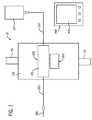
- FIG. 1is a schematic view of a testing system according to one embodiment
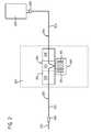
- FIG. 2shows a more detailed schematic view of disposable portions of a testing system according to the embodiment of FIG. 1 ;
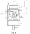
- FIG. 3shows a more detailed schematic view of reusable portions of the testing system according to the embodiment of FIG. 1 ;
- FIG. 4is a pictorial view illustrating a testing system according to a further embodiment
- FIG. 5is a pictorial view illustrating disposable components of the testing system according to the embodiment of FIG. 4 ;
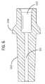
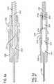
- FIG. 6is a sectional view of a connector taken along line 6 - 6 of FIG. 5 ;
- FIG. 6 ais a sectional view showing the connector of FIG. 6 assembled with distal tubing and a catheter;
- FIG. 6 bis a sectional view showing a prior art standard Luer connector assembled with distal tubing and a catheter;
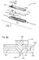
- FIG. 7is an exploded view illustrating a disposable testing cassette for use with the testing system according to the embodiment of FIG. 4 ;
- FIG. 7 ais a cross-section view taken along line 7 a - 7 a of FIG. 7 ;
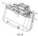
- FIG. 7 bis pictorial view illustrating a testing system according to yet a further embodiment
- FIG. 8 ais a cross-section view taken along line 8 - 8 of FIG. 7 depicting a valve portion of the cassette in a closed position;
- FIG. 8 bis a cross-section view taken along line 8 - 8 of FIG. 7 depicting a valve portion of the cassette in an open position;
- FIG. 9is a pictorial view illustrating a disposable off-line testing disk for use with the testing system shown in FIG. 4 ;
- FIG. 10is a pictorial view illustrating movable mechanisms of the testing system according to the embodiment of FIG. 4 ;
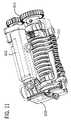
- FIG. 11is a pictorial view depicting a peristaltic pump mechanism for use with the testing system shown in FIG. 4 ;
- FIG. 12is a cross-sectional view taken along line 12 - 12 of FIG. 10 depicting the peristaltic pump interacting with the cassette for pumping fluid into or out of the cassette;
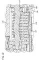
- FIG. 13is a pictorial view illustrating an actuator adapted to operate the valve of the cassette as shown in the embodiment of FIG. 7 ;
- FIG. 14 ais a cross-sectional view depicting the actuator depicted in FIG. 13 interacting with the cassette with the valve in a closed position;
- FIG. 14 bis a cross-sectional view depicting the actuator depicted in FIG. 13 interacting with the cassette with the valve in an open position;
- FIG. 15is a bottom pictorial view of a rotating mechanism for the disposable off-line testing disk for use with the testing system shown in FIG. 4 ;
- FIG. 16is a top pictorial view of a rotating mechanism for the disposable off-line testing disk for use with the testing system shown in FIG. 4 .
- FIG. 1is a schematic representation of a point-of-care testing system 10 comprising a main body 100 adapted to be attached to a patient via two attachment straps 101 .
- the attachment straps 101may attach the main body 100 of testing device 10 to the patient via a VELCRO® fastener or other similar temporary attachment methods, such as an adhesive, that allows the attachment straps 101 to be removably attached to each other to secure the main body 100 to a desired location.
- a VELCRO® fasteneror other similar temporary attachment methods, such as an adhesive, that allows the attachment straps 101 to be removably attached to each other to secure the main body 100 to a desired location.
- the main body 10is relative small, having a volume of less than about twenty (20) cubic inches, and weighing less than about two (2) pounds. It is further contemplated that the main body 100 may additionally be contoured to be applied to a specific body part of a patient, such as a forearm, leg, or abdomen. While such a contour is not required, it may improve patient comfort. It is contemplated that in many cases the forearm will serve as a beneficial mounting location based on the ease of access and the number of blood vessels in the forearm.
- the main body 100may be reusable, in that it may be used on more than one patient, by following proper cleaning and sterilization techniques before being used with another patient. It is further contemplated that the main body 100 can be releasably secured to a bed rail, pole, or other support structure near the patient's bedside rather than being worn by the patient.
- the testing system 10additionally comprises a disposable portion 200 .
- the disposable portiondescribed in more detail below, is adapted to be used with only one single patient and may require periodic replacement on that patient.
- a catheter 205is adapted to be placed into a blood vessel of the patient.
- the catheter 205may be a standard 20 Gauge ⁇ 2 inch catheter, or other commonly available catheter appropriate for the blood vessel utilized.
- the blood vessel selectedmay be an artery or a vein. If blood gas levels, or properties that may vary based on blood gas levels, are to be monitored the blood vessel selected will be an artery.
- a veinmay be used if blood gases are not of interest or do not affect the property or properties to be determined using the testing system.
- the main body 100 of the testing systemis preferably located near the location where the catheter 205 is placed into the blood vessel, in order to minimize the volume of blood needed for a sample. It is contemplated that the main body 100 will be positioned within one hundred centimeters (100 cm), more preferably within about twenty centimeters (20 cm), of the location the catheter 205 enters the blood vessel.
- the main body 100houses, removably receives, or operatively couples with two disposable portions, a primary fluid routing portion 201 and a secondary fluid routing portion 300 .
- the primary fluid routing portion 201has an in-line testing region that includes an in-line sensor 209 .
- the secondary fluid routing portion 300includes a secondary fluid routing portion 301 .
- the primary fluid routing portion 201 and the secondary fluid routing portion 300are selectively connectable in fluid communication through a fluid transfer region 210 .
- in-line testingrefers to blood testing where substantially all of the blood that enters the testing portion may be returned to the patient, while off-line testing is used to refer to blood testing where the blood will not be returned to the patient.
- in-line testingrefers to blood testing where substantially all of the blood that enters the testing portion may be returned to the patient
- off-line testingis used to refer to blood testing where the blood will not be returned to the patient.
- the secondary fluid routing portion 300is connected to the primary fluid routing portion 201 .
- the blood that enters the secondary fluid routing portion 300 of the system 10was initially within the primary fluid routing portion 201 .
- Only a relatively small fraction of the blood within the primary fluid routing portion 201is transferred into the secondary fluid routing portion 300 .
- the portion transferred to the secondary fluid routing portioncould be fifty microliters (50 ⁇ L).
- the testing system 10additionally comprises a flush solution reservoir 207 .
- the flush solution reservoir 207contains a flush solution adapted to flush the blood out of the system 10 prior to the initiation of a test, or to reinfuse the blood back to the patient following the completion of a test.
- the flush solutionmay be a medically-approved water-based solution including but not limited to saline, dextrose and water, potassium chloride, electrolytes, etc.
- the flush solutionadditionally may be used to prime the testing system 10 prior to connecting the system to the patient.
- the system 10may need to be primed to ensure that air is not present in fluid passages of the system 10 .
- the flush solutionmay contain one or more substances used to calibrate an in-line test sensor 209 ( FIG.
- the initial volume of flush solution within the flush solution reservoir 207should be sufficient to prime the testing system 10 and operate the system 10 for a period of from about 12 hours to about 96 hours. According to some embodiments the initial volume of flush solution may range from about 100 mL to about 1000 mL. It is additionally contemplated according to some embodiments that some portion of the flush solution within the reservoir 207 may be used to keep the patient's blood vessel open at the site of the catheter 205 .
- the primary fluid routing portion 201 and the secondary fluid routing portion 300are adapted to be placed within the main body 100 of the testing system 10 by a caregiver at the start of care of the patient, or when the portions 201 , 300 need replacement. It is contemplated that the portions 201 , 300 may be used for a period of up to 96 hours prior to replacement.
- control device 400The main body 100 of the testing system 10 communicates with a control device 400 .
- the control device 400has a user interface 401 to allow the caregiver to view results of tests performed automatically by the system 10 and to set the frequency of testing.
- the user interface 401may be a touch screen, or other known user interface types, to allow the caregiver to easily communicate with the system 10 .
- the control device 400may be an infusion pump, such as a SYMBIQ® infusion system or pump by Hospira, Inc., that is being used to provide medication or other fluids to a patient.
- Wireless communication between the main body 100 of the testing system 10 and the control device 400is preferred, as a wireless system does not require the caregiver to route communication cables from the body 100 to the control device 400 .
- the communications between the main body 100 and the control device 400will be carried via a wire or cable.
- the main body 100 of the testing system 10can have its own integral control device and/or user interface to display test results and accept operational commands. The test results over a particular selectable time period of interest can be displayed in graphical or other suitable format.
- the disposable portion 200provides a continuous fluid passage from the patient's blood vessel via the catheter 205 through the main body 100 of the testing system 10 and to the fluid reservoir 207 .
- the disposable portion 200has a distal end at the catheter 205 that is inserted into the patient's blood vessel.
- the catheter 205connects to a distal connecter 204 that is also connected to a first fluid line portion 202 .
- the first fluid line portion 202runs from the distal connector 204 to the primary fluid routing portion 201 within the main body 100 (shown in broken lines in FIG. 2 ) of the testing device 10 .
- the first fluid line portion 202is a flexible tubing that may be conveniently routed by the caregiver.
- the first fluid line portion 202may be from about 10 cm to about 50 cm in length, and preferably has an internal volume of less than about two-hundred microliters (200 ⁇ L).
- the distal connector 204may be of any suitable leak-proof design, such as a Luer type connector, that preferably has a fluid volume of less than about twenty microliters (20 ⁇ L) when the connector 204 is connected to the catheter 205 and the first fluid line portion 202 .
- the disposable portion 200additionally comprises a second fluid line portion 203 .
- the second fluid line portion 203runs from the primary fluid routing portion 201 within the main body 100 to a proximal connecter 206 connected to the flush solution reservoir 207 .
- the second fluid line portion 203may be significantly longer than the first fluid line portion 202 in order to conveniently locate the flush solution reservoir 207 away from the patient, such as on a fixed or portable bedside pole.
- the internal volume of the second fluid line portion 203may be more than ten times the internal volume of the first fluid line portion 202 .
- Providing the second fluid line portion 203 with much greater internal volume than the first fluid line portion 202reduces the likelihood of contaminating the flush solution reservoir with blood that has entered the system 10 .
- the proximal connector 206may be a Leur type connector, a tapered spike, needle cannula, or any other known type of connector for accessing the fluid in the reservoir 207 .
- the primary fluid routing portion 201may be divided into three main regions, a fluid pumping region 208 , a fluid testing region 209 , and a fluid transfer region 210 .
- the primary fluid routing portion 201may be in the form of a disposable cassette containing the pumping region 208 , the fluid testing region 209 , and the fluid transfer region 210 .
- the total volume of fluid within the primary fluid routing portion 201is preferably less than three hundred microliters (300 ⁇ L).
- the fluid testing region 209can be an in-line fluid testing region.
- the pumping region 208 of the primary fluid routing portion 201is a fluid passage that interacts with a pump contained in the main body 100 .
- the pumping region 208may have an elastic region, such as a silicone membrane or polymeric tubing, which engages a peristaltic-type pump, or other type pump, within the body 100 .
- the pumping region 208allows for bi-directional flow within the primary fluid routing portion 201 , i.e., fluid may flow either away from the patient or back towards the patient, depending upon the operation of the pump.
- the pumping region 208further is adapted to stop all flow within the primary fluid routing portion 201 when the pump is stopped. Flow may be stopped in order to perform certain fluid testing within the in-line fluid testing region 209 of the primary fluid routing portion 201 .
- the fluid testing region 209is a fluid passage having at least one integrated sensor adapted to determine information about the patient's blood.
- the informationmay include determining the level of certain analytes within the blood, such as the patient's blood glucose level.
- the sensor disposed within the testing region 209can be a single use sensor, but is more preferably a reusable sensor capable of performing a plurality of blood sample analyte measurements over the life of the disposable portion 200 or the primary fluid routing portion 201 .
- the testing region 209may contain a sensor, or sensors, capable of measuring blood glucose, blood gases, electrolytes, lactate, and other analytes.
- the sensor, or sensors, of the testing region 209may utilize electrochemical, optical, calorimetric, or other known technologies for measuring blood analytes.
- the testing region 209additionally is adapted to electrically communicate results of testing to the rest of the system 10 , such as by electrodes or other wired or wireless circuitry.
- the fluid transfer region 210 of the primary fluid routing portion 201allows a small volume of blood within the primary fluid routing portion 201 to be deposited, expressed, or otherwise transferred to the secondary fluid routing portion 300 .
- the blood, or other fluid, that is transferred to the secondary fluid routing portion 300never reenters the primary fluid routing portion 201 , but remains in secondary fluid routing portion 300 .
- the fluid transfer region 210allows the secondary fluid routing potion 300 to be utilized to perform testing that takes a longer period of time to perform, or requires a reaction that makes the blood unsuitable to return to the patient.
- a non-limiting example of a test to be performed in the secondary fluid routing portion 300is a blood coagulation test, as coagulated blood should not be returned to the patient.
- the small volume of blood transferred through the fluid transfer region 210 to the secondary fluid routing portion 300should be less than about twenty microliters (20 ⁇ L) per transfer. It is contemplated that a transfer through the transfer region 210 of the primary fluid routing portion 201 to the secondary fluid routing portion 300 may be made every time a blood sample is taken from the patient via the system 10 . It is further contemplated that some tests utilizing the secondary fluid routing portion 300 may not need to be taken as frequently as tests utilizing the testing region 209 of the primary fluid routing portion 201 , and in such a situation a portion of only selected blood samples would need to be transferred through the transfer region 210 to the secondary fluid routing portion 300 .
- a plurality of transfers through the transfer region 210 to the secondary fluid routing portion 300 and secondary fluid routing portion 301may be made per blood sample. For instance, a small amount of flushing solution may first be transferred to the secondary fluid routing portion 300 prior to any blood being pumped into the primary fluid routing portion 201 . Then blood from the patient may be transferred from the primary fluid routing portion 201 . Finally, a third transfer may provide flushing solution into the secondary fluid routing portion 300 as the flushing solution is used to pump the blood from the primary fluid routing portion back into the patient.
- the transfer region 210 of the primary fluid routing portion 201may have a valve, a fluid circuit, or other known fluid transfer device that can be activated by a mechanism located remotely or within the main body 100 in order to facilitate the transfer of fluid from the primary fluid routing portion to the secondary fluid routing portion.
- the transfer region 210must be designed to prevent leakage of fluid, prevent the introduction of air, and prevent the introduction of microbes during the transfer from the primary fluid routing portion 201 to the secondary fluid routing portion 300 . Additionally, the transfer region 210 must permit a plurality of transfers to occur successively, without becoming either clogged or adversely affected by fluids previously transferred during the lifespan of the primary fluid routing portion 201 .
- the disposable secondary fluid routing portion 300is in fluid communication with the primary fluid routing portion 201 via the transfer region 210 .
- the secondary fluid routing portion 300has an off-line testing portion 301 comprising one or more, more preferably an array or plurality of spaced apart single use diagnostic sensors 301 .
- the sensors 301may be, but are not limited to, blood coagulation sensors, such as for use with a PT, aPTT, or ACT blood coagulation test.
- the fill volume for each sensor 301is preferably less than about twenty microliters (20 ⁇ L).
- the secondary fluid routing portion 300is adapted to sequence the sensors 301 such that each sensor 301 can receive a volume of blood transferred from the transfer region 210 of the primary fluid routing portion 201 , while also preventing the sample volume from contacting other sensors in the array.
- the sensors 301may be sequenced by a rotating platform, a linear translating platform, a fluid circuit with valves that operate sequentially, or other known sequencing methods.
- the sample transferred into the secondary fluid routing portion 300may reach an individual sensor 301 via capillary action, or by pumping from the pumping region 208 of the primary fluid routing portion 201 for a brief time period, such as less than ten seconds.
- the secondary fluid routing portion 300additionally is adapted to electrically communicate results of testing on a test sensor 301 to the rest of the system 10 , such as by electrodes, or other wired or wireless circuitry.
- the secondary fluid routing portion 300may also be positioned within the main body 100 in order to receive heat from a heater 106 within the main body 100 , such that any tests performed in the secondary fluid routing portion are performed under proper temperature conditions.
- the secondary fluid routing portion 300is adapted to contain from about 1 to about 36 test sensors 301 , depending on the required frequency of off-line testing. Due to the fluid transfer region 210 , if the secondary fluid routing portion 300 contains single use sensors 301 or supports a different frequency of testing that the primary fluid routing portion 201 , the secondary fluid routing portion can be removed from the main body 100 independently of the primary fluid routing portion 201 , without having to remove the system 10 from the patient. Thus, a caregiver may replace the secondary fluid routing portion 300 while the testing system 10 is still connected to the patient and without the need to change the primary fluid routing portion 201 . This is particularly useful if the number of off-line test sensors 301 that may be placed in the secondary fluid routing portion 300 is small, or if a caregiver determines that a different analyte level or blood property needs to be monitored on the patient.
- the main body 100is adapted to be used on a plurality of patients over a number of years. It is contemplated that the main body 100 may be used for up to three years or longer with proper care. Proper sterilization and cleaning procedures must be followed between uses of the main body 100 on different patients.
- the main body 100comprises an opening 102 for receiving one or more of the disposable portions 201 , 300 , a pump 103 , a fluid transfer mechanism 104 , an off-line sensor indexer 105 , a heating element 106 , a controller 107 , and a power source 108 .
- the main body 100has an access door 111 (not shown) that allows a caregiver to access the opening 102 , such as to replace the primary fluid routing portion 201 , or the secondary fluid routing portion 300 (shown in broken lines).
- a caregiverwill use the access door 111 to place a primary fluid routing portion 201 and the secondary fluid routing portion 300 into the body 100 at the beginning of use of the system 10 on a particular patient, and to remove the testing portions 201 , 300 from the body 100 at the conclusion of use of the system 10 on the patient.
- the access door 111may be positioned so as to be utilized to replace the secondary fluid routing portion 300 while the system is connected to the patient.
- the pump 103is a mechanism, such as a peristaltic pump, piezo element, magnetic field, or other known pump type, that causes fluid to flow inside of the pumping region 208 of the primary fluid routing portion 201 .
- the pump 103is bi-directional or capable of causing fluid to flow in either direction, away from the patient or towards the patient, within the testing system 10 .
- a uni-directional pumpcan be used with appropriate valving to achieve bi-directional flow.
- the flow rate provided by the pump 103must be sufficient to allow testing operations to be completed within a two minute period by drawing blood into the system, performing in-line testing, transferring blood for off-line testing, and re-infusing the blood remaining in the primary fluid routing portion back into the patient.
- the pump 103is also adapted to completely stop flow within the primary fluid routing portion 201 , such as when an in-line test is performed in the in-line testing region 209 .
- the fluid transfer mechanism 104may include a motorized cam, a piston, a magnet, or other known methods to cause the transfer region 210 of the primary fluid routing portion 201 to transfer fluid from within the primary fluid routing portion to the secondary fluid routing portion 300 .
- the sensor indexer 105may be a rotational motor or linear motor, or other type device that positions an individual sensor 301 relative to the transfer region 210 to receive fluid from the primary fluid routing portion 201 via the transfer region 210 .
- the heating element 106provides thermal energy to regulate the temperature of at least one of the sensors 301 of the secondary fluid routing portion 300 to help ensure accurate test results.
- the heating elementmay regulate the temperature of the sensor 301 to about 37° C. during the period of testing for a blood coagulation sensor.
- the heating element 106may be stationary and the sensor indexer 105 will position the individual sensor 301 near the heating element 106 .
- the heating element 106may be movable so as to be positioned near the individual sensor 301 or both the heating element 106 and the sensor 301 may be movable for that purpose.
- a plurality of heating elements 106may be provided such that every individual sensor 301 of the secondary fluid routing portion 300 is provided with a heating element 106 .
- a reusable fluid sensor 211may additionally be incorporated into the main body 100 and is functionally engaged with the in-line testing region 209 of the disposable portion 200 .
- the fluid sensor 211produces a signal, such as an electric signal, that varies in strength based on the composition of the fluid in the in-line testing region 209 .
- the fluid sensor 211may be used for determining, for example, if a blood sample has been drawn into the in-line testing region 209 , and subsequently, if the blood sample has been fully flushed from the in-line testing region 209 by a flush solution after an in-line diagnostic test has been performed.
- the fluid sensor 211may also be used for detecting the presence of an unwanted air pocket inside the test region.
- the fluid sensor 211can thereby add a measure of efficacy to the testing system 10 by providing an ability to confirm proper flow of blood and flush solution inside the disposable portion 200 while ensuring that no air is present.
- the reusable fluid sensor 211may comprise an optical sensor, such as a paired LED emitter and photo-detector unit, or some other reusable sensor capable to distinguish between blood, flush solution, and air within a sensing zone of the disposable portion 200 .
- the fluid sensor 211may be a suitable disposable design that is integral to the disposable portion 200 and comes into contact with the fluid, such as an electrochemical or electrically conductive sensor, which is disposed along with the cassette upon completion of use on a patient.
- the fluid sensor 211may alternatively be located elsewhere in the disposable portion 200 or elsewhere along the disposable set; however, it is preferred to locate the sensor 211 in close proximity to where the blood sample is tested for diagnostic analysis.
- the controller 107is adapted to operate and functionally coordinate all of the electromechanical components, such as the pump 103 , the fluid transfer mechanism 104 , the off-line sensor indexer 105 , and the heating element 106 of the testing system 10 .
- the controller 107also allows the main body 100 to communicate with the control device 400 ( FIG. 1 ) to report test results from the testing system 10 or to obtain instructions from the caregiver entered via the control device 400 .
- the power source 108 of the main body 100is a battery, such as a lithium ion battery, that provides sufficient power to operate the system for an extended period of time, such as between eight and seventy-two hours.
- the power source 108may be an A/C power source. If the power source 108 is a battery, it may be rechargeable or disposable. It is contemplated that if a rechargeable battery is used for the power source 108 , the power source may be recharged while the system 10 is in use on a patient.
- the testing system 1000comprises a reusable main body 1100 , a disposable assembly 1200 , including the primary fluid routing portion 1201 and the secondary fluid routing portion 1300 , described in greater detail in connection with FIG. 5 , a catheter 1205 to connect to a blood vessel of a patient, a flush solution reservoir 1207 , and a control device 1400 .
- the testing system 1000 shown in FIG. 4is adapted to perform an in-line blood glucose test and an off-line blood coagulation test; however, it is contemplated that other analytes or blood properties could be tested as described in connection with FIGS. 1-3 .
- the main body 1100has a primary fluid routing portion access door 1102 and a secondary fluid routing portion access door 1111 .
- the primary fluid routing portion access door 1102allows a care giver to access the primary fluid routing portion 1201
- the secondary fluid routing portion access door 1111allows a caregiver to replace the secondary fluid routing portion 1300 without having to worry about disrupting the primary fluid routing portion 1201 .
- the main body 1110 shown in FIG. 4measures approximately 4.75′′ ⁇ 3.75′′ ⁇ 1.7′′ giving a total volume of approximately 30 cubic inches.
- the main body 1100has a total weight of about 0.75 lbs.
- a strap 1101 with a VELCRO® type connectorallows the main body 1100 to be releasably secured to a patient, such as by attaching the strap 1101 around a patient's arm or leg.
- the control device 1400 shown in FIG. 4is a SYMBIQ® infusion system or pump from Hospira.
- the control device 1400has a touch screen user interface 1401 to allow the caregiver to enter instructions for the testing system 1000 and to view results of tests performed by the testing system 1000 .
- the control device 1400 and the main body 1100communicate wirelessly in the embodiment shown in FIG. 4 , although a wired connection would also suffice.
- FIG. 5illustrates the disposable portions 1200 , 1300 of the testing system 1000 .
- the disposable portion 1200provides the main fluid path of the testing system 1000 .
- the disposable portion 1200has the catheter 1205 at a distal end and the flush fluid reservoir 1207 at a proximal end.
- the catheter 1205connects to a distal connector 1204 .
- the distal connector 1204also connects to a first fluid line portion or distal tubing 1202 .
- the first fluid line portion 1202runs from the distal connector 1204 to the primary fluid routing portion 1201 .
- the first fluid line portion 1202has a length of about 25 cm, and an inner diameter of about 0.030′′, giving the first fluid line portion 1202 a relatively small internal volume of 114 ⁇ L.
- the distal connector 1204is a low-volume distal connector.
- the low volume of the distal connector 1204is obtained by providing a bore 1211 having a 1 cm length and a 0.030′′ diameter, providing a volume of about 5 ⁇ L.
- the outer surface 1212 of the distal connectoris designed to be completely inserted into the catheter 1205 , thereby eliminating any excess fluid volume in the catheter 1205 caused by incomplete insertion.
- the diameter of the bore 1211matches the diameter of the bore 1222 of the distal tubing 1202 .
- a receptacle 1213is sized and shaped to allow a complete insertion of the distal tubing 1202 into the distal connector 1204 , eliminating any excess volume or dead space caused by incomplete insertion of the distal tubing 1202 .
- the low volume distal connector 1204 of FIGS. 6 and 6 aoffers improvements over a prior art Luer type connector shown in FIG. 6 b by reducing the internal volume of the fluid flow path between the blood vessel and the primary fluid routing portion 1201 and eliminating dead spaces where fluid may tend to stagnate.
- the bore 1211 bdoes not match the bore 1222 of the distal tubing 1202 , the outer surface 1212 b is not designed to be completely inserted into the catheter 1205 , and the receptacle 1213 b is not sized and shaped to allow complete insertion of the distal tubing 1202 .
- Thiscauses dead spaces or locations, generally designated at 1222 , 1223 , and 1224 where blood may collect and resist flushing back into the patient following in-line testing.
- the connector 1204 of the present inventionprovides a substantially smooth, continuous, uninterrupted fluid flow path that is free from dead spaces or locations where blood may collect and resist flushing back into the patient. Blood is not allowed to stagnate in the lines, posing health risks to the patient or caregiver and possibly skewing results of subsequent tests.
- the primary fluid routing portion 1201has a pumping region 1208 , a testing region 1209 , and a fluid transfer region 1210 .
- the fluid transfer regionis aligned with the secondary fluid routing portion 1300 to provide a sample to a test sensor 1301 ( FIG. 9 ) of the secondary fluid routing portion 1300 .
- the primary fluid routing portion 1201has an internal flow path with a volume of about 175 ⁇ L.
- the primary fluid routing portion 1201 and the first fluid line portion 1202combine to have a volume of about 295 ⁇ L.
- the primary fluid routing portion 1201connects to a second fluid line portion 1203 that also connects to a proximal connector 1206 at the flush fluid reservoir 1207 .
- the second fluid line portionhas a length of about 90 cm and an internal diameter of about 0.054′′, providing an internal volume of about 1330 ⁇ L.
- the primary fluid routing portion 1201has a lid 1201 a and a base 1201 b .
- a flexible silicone diaphragm 1214seals the primary fluid routing portion from fluid leakage, as well as preventing air or other outside contaminants from entering the primary fluid routing portion 1201 .
- An in-line test sensor 1215is provided in the primary fluid routing portion 1201 to measure the concentration of glucose within the blood that enters the primary fluid routing portion 1201 .
- the test sensor 1215includes electrodes 1216 that are exposed outside of the primary fluid routing portion 1201 to provide the results from the test sensor 1215 to the system 1000 .
- the sensor 1215is a thick-film design having a glucose-oxidase reagent that is reusable for up to 1000 test cycles over a 30 day period.
- the primary fluid routing portion 1201additionally forms a fluid channel 1217 running the length of the primary fluid routing portion 1201 .
- the primary fluid routing portion 1201has a fluid sensing zone 1225 . Fluid that enters and exits the primary fluid routing portion 1201 passes through the fluid sensing zone 1225 . It is contemplated that the fluid sensing zone 1225 is an optically transparent material, such as, for example, a clear polycarbonate polymeric material.
- the fluid sensing zone 1225is located near, and generally proximal to, the in-line test sensor 1215 , to allow an identification to be made of fluid within the primary fluid routing portion 1201 and nearing the test sensor 1215 .
- the close proximity of the fluid sensing zone 1225 to the in-line test sensor 1215allows the testing system 1000 to determine that a desired fluid to be sampled is in contact with the test sensor 1215 .
- FIG. 7 aa sectional view taken through line 7 a - 7 a of FIG. 7 is shown.
- FIG. 7 ashows a raised fluid channel portion 1226 of the fluid channel 1217 within the fluid sensing zone 1225 . Fluid within the fluid channel 1217 that enters the fluid sensing zone 1225 passes through the raised fluid channel 1226 .
- the raised fluid channel 1226allows an optical sensor ( 1227 FIG. 7 b ) to transmit light through the fluid sensing zone 1225 and generate an output used to determine what type of fluid is present within the fluid sensing zone 1225 .
- the raised fluid channel portion 1226extends beyond, generally higher, than the remainder of the fluid channel 1217 , and the in-line test sensor 1215 .
- FIG. 7 bshows an arrangement of the fluid sensing zone 1225 and an optical sensor 1227 .
- the optical sensor 1227is contained within the main body 1100 . It is contemplated that the optical sensor 1227 may be located within the primary fluid routing portion access door 1102 . The optical sensor 1227 positions around the fluid sensing zone 1225 when the primary fluid routing portion 1201 is within the main body 1100 and the access door 1102 is closed. The access door 1102 has been removed from FIG. 7 b for greater clarity.
- the optical sensor 1227may be an LED type sensor. That is, light is emitted from an LED of the optical sensor 1227 , the light passes through the fluid sensing zone 1225 , and the light is detected by an optical detector of the optical sensor 1227 . The optical detector of the optical sensor 1227 generates an output related to the intensity of the light received by the optical sensor 1227 .
- Various fluids that are typically found within the fluid sensing zone 1225have distinct optical properties such that the output signals of the optical sensor 1227 for the various fluids within the sensing zone 1225 are distinguishable.
- Lightis altered by refraction, scattering, reflection, and absorption as it passes through a fluid present in the sensing zone 1225 as it passes from the LED to the optical detector of the optical sensor 1227 .
- the intensity of the light that reaches the optical detector of the optical sensor 1227allows a determination to be made of the fluid, blood, flush solution, air, or some other fluid, present within the sensing zone 1225 .
- the output of the optical sensor 1227may then be compared to stored light intensity profiles to allow a determination of the identity of the fluid within the sensing zone 1225 .
- a light intensity profile for blood and a light intensity profile for flush solutionmay be stored on a memory.
- An algorithm executed by a processorcompares the output generated by the optical sensor 1227 with stored light intensity profiles to determine the identity of the fluid present in the sensing zone 1225 .
- a processormay determine that the output generated by the optical sensor 1227 is not consistent with any stored pattern, and alert a caregiver that a malfunction has occurred, such as an abnormal fluid flow condition, or the presence of an air slug within the line.
- FIGS. 8 a and 8 bdepict a cross section taken along line 8 - 8 of FIG. 7 showing the fluid transfer region 1210 of the primary fluid routing portion 1201 .
- the fluid transfer region 1210has a valve 1218 that comprises a silicone valve plug 1219 , that may be integrally formed with the diaphragm 1214 ; a valve nozzle 1220 , that may be formed into the base 1201 b of the primary fluid routing portion 1201 ; and a leaf spring 1221 that connects to and exerts a force on the valve plug 1219 to keep the valve closed until activation is desired. As shown in FIG.
- valve plug 1219is in the closed position, and fluid is not allowed to pass through the valve, but fluid may flow in the fluid channel 1217 of the primary fluid routing portion 1201 .
- valve plug 1219is in the open position, and fluid is allowed to pass through the valve nozzle 1220 .
- the secondary fluid routing portion 1300where secondary testing such as off-line testing can be done, is depicted.
- the secondary fluid routing portion 1300has at least one test sensor 1301 , which may be a single use or multiple use sensor.
- an absorbent pad 1302can be provided.
- the exemplary embodiment depicted in FIG. 9shows that the secondary fluid routing portion 1300 can include a plurality of test sensors 1301 and a plurality of absorbent pads 1302 .
- the test sensors 1301 shownare single use blood coagulation sensors.
- the coagulation test sensors 1301may use a PT reagent, an aPTT reagent, or an ACT reagent.
- a sample of blood from the primary fluid routing portion 1201is transferred through the fluid transfer region 1210 and onto the test sensor 1301 for off-line testing. It is contemplated that a sample as small as 5 ⁇ L may be used for blood coagulation testing with a PT reagent.
- the test sensor 1301can absorb a 5 ⁇ L sample in about 5 seconds using capillary action. Electrodes (not shown) relay the results of the coagulation test to the system 1000 .
- the system 1000has a pump 1103 , a valve actuator 1104 , and an off-line testing portion sensor indexer 1105 .
- the pump 1103 and the valve actuatorwork in conjunction with the primary fluid routing portion 1201 of the system 1000 , while the off-line testing portion sensor indexer 1105 works in conjunction with the secondary fluid routing portion 1300 .
- the pump 1103is shown in more detail in FIG. 11 .
- the pump 1103has a motor 1112 , a peristaltic portion 1113 having peristaltic fingers mounted on a camshaft, and a set of gears 1114 to allow the motor 1112 to drive the peristaltic portion 1113 .
- the motor 1112is operable in either direction, thus allowing the pump to be operated to draw fluid into the primary fluid routing portion 1201 , or to pump fluid out of the primary fluid routing portion 1201 or back in the direction from which it entered. Therefore, the pump 1103 provides for bidirectional flow within the system 1000 .
- FIG. 12depicts a cross-section showing the pump 1103 interacting with the pump region 1208 of the primary fluid routing portion 1201 .
- the peristaltic fingers of the peristaltic portion 1113 of the pump 1103compress the silicone diaphragm 1214 in the pump region 1208 of the primary fluid routing portion 1201 .
- the fingerssequentially press against the diaphragm 1214 to cause fluid to flow in flow channel 1217 of the primary fluid routing portion 1201 and the system 1000 .
- at least some of the fingersare positioned to compress the diaphragm 1214 sufficiently so that no fluid may flow through the flow channel 1217 when the pump 1103 is not in operation and the cassette 1201 is properly installed.
- FIGS. 13 , 14 a , and 14 bshow the valve actuator 1104 in more detail.
- the valve actuator 1104has a motor 1115 that drives a camshaft 1116 via gears 1117 .
- the cam shaft 1116operates a valve pin 1118 and a diaphragm pin 1120 .
- the valve pin 1118has a spring 1121 and the diaphragm pin 1120 has a spring 1122 that hold the pins 1118 , 1120 in contact with the camshaft 1116 .
- the valve pin 1118has a magnet 1119 on the end of the pin closest to the primary fluid routing portion or cassette. To open the valve 1218 , as shown in FIG.
- the camshaft 1116turns, allowing the spring 1121 to push the valve pin 1118 away from the primary fluid routing portion 1201 .
- the magnet 1119lifts up a leaf spring 1221 that is connected to the valve plug 1219 , pulling the valve plug 1219 away from the valve nozzle 1220 to allow fluid to flow through the valve nozzle 1220 .
- the motion of the camshaft 1116causes the diaphragm pin 1120 to move towards the primary fluid routing portion 1201 .
- the diaphragm pin 1120compresses the silicone diaphragm 1214 so that fluid may not be pumped distally beyond the location of the pin 1120 in the flow channel 1217 of the primary fluid routing portion 1201 .
- the pump 1103may be run for a short period of time to more quickly drain fluid from the primary fluid routing portion 1201 to the secondary fluid routing portion 1300 .
- the camshaft 1116rotates to push the valve pin 1118 back towards the primary fluid routing portion 1201 , thus replacing the valve plug 1219 .
- the diaphragm pin 1120is moved away from the primary fluid routing portion to allow flow to resume through the flow channel 1217 , as shown in FIG. 14 a .
- the period to open or close the valve 1218is less than five seconds.
- the off-line sensor portion indexer 1105has a carousel 1123 that supports the off-line testing portion 1300 to properly position the off-line test sensors 1301 and the absorbent pads 1302 .
- the sensor indexer 1105drives the carousel 1123 via geared surface 1124 .
- the rotational position of the carousel 1123is sensed by monitoring movement of flags 1125 through an optical detector 1126 .
- a set of pins 1127contact electrodes on the off-line test sensors 1301 to obtain results from the off-line test sensors.
- a heater 1106used to maintain an appropriate temperature of the off-line test sensor 1301 being used.
- the heaterhas an aluminum element 1128 that contact the sensor 1301 to transfer heat to the sensor 1301 .
- the element 1128is heated by a Kapton pad 1129 that is electrically energized.
- a thermistor 1130 embedded in the element 1128monitors the temperature.
- the heater 1106is mounted in a fixed location, and an individual sensor 1301 is rotated to the heater 1106 by the carousel 1123 .
- each sensor 1301may include a heater 1106 that rotates with it or the heater 1106 can be on a second carousel geared to rotate relative to the sensor carousel 1123 .
- a method of using the point-of-care testing system 10 on a patientmay comprise attaching the main body 100 to the patient's forearm to monitor blood glucose level and coagulation (aPTT) rate at prescribed intervals of time over a twenty-four hour period.
- An infusion system or pump 400 near the patienthas been configured to function as the graphical user interface 401 for the system 10 via wired or wireless communication.
- the infusion pump 10may also serve to deliver one or more drugs to the patient, such as insulin and heparin.
- a caregiver or cliniciangathers the basic components of the system in preparation for use on the patient, including the main body 100 , the disposable portion 200 (including the primary fluid routing portion 201 and/or the secondary fluid routing portion 300 ), and the reservoir of flush solution 207 .
- the clinicianalso obtains a standard catheter 205 suitable for drawing blood from a peripheral vein on the patient's forearm.
- the disposable 200 portionincorporates a glucose sensor in the diagnostic sensor region 209
- the disposable secondary fluid routing portion 300incorporates an array of six aPTT coagulation sensors.
- the clinicianattaches the body 100 to the patient via the attachment features 101 , such that the body 100 is located about three inches from a site chosen to catheterize a peripheral vein or artery.
- the forearmprovides a convenient location for mounting the body 100 to the patient and accessing a peripheral blood vessel, although other mounting locations and blood vessel access points are possible.
- the clinicianthen assembles the disposable portions 200 , 300 of the system, by connecting the distal connector 204 to the catheter 205 , connecting the secondary fluid routing portion 300 to the primary fluid routing portion 201 , and connecting the proximal connector to the flush solution 207 reservoir.
- the clinicianprimes all the fluid passages in the system 10 with flush solution by holding the flush solution reservoir 207 at an elevation that causes gravity to force the flush solution through all passages from the reservoir 207 to the tip of the catheter 205 .
- the clinicianobserves that all air has been removed from these passages.
- the clinicianinserts the catheter 205 into the peripheral vein or artery on the patient, using appropriate hospital procedures, to provide access to the patient's blood vessel.
- the clinicianimmediately installs the primary fluid routing portion 201 and the secondary fluid routing portion 300 into the main body 100 via the opening 102 ( FIG. 3 ).
- the installationautomatically prevents the flow of flush solution inside the primary fluid routing portion 201 , by virtue of the pump 103 engaging the primary fluid routing portion 201 .
- the clinicianthen hangs the flush solution reservoir 207 on a bedside pole.
- the clinicianactivates (“turns on”) the invention via the graphical interface 401 on the infusion pump 400 .
- the system 10is subsequently energized by the internal power source 108 .
- Wireless communication between the main body and the infuser 400begins, via a set of wireless transmission components on the electronic controller 107 and in the infuser 400 .
- the clinicianprograms the system 10 via the graphical interface 401 to perform a series of 24 blood draws on the patient, spaced 1 hour apart. Furthermore, the clinician programs the invention to perform a glucose test on each blood sample drawn, and also to perform an aPTT test on every second blood sample drawn (i.e., at 2-hour intervals). The net result will be 24 glucose tests and 12 aPTT tests uniformly spaced over a 24-hour period.
- the system 10begins to respond to the instructions programmed by the clinician. All acts done by the system 10 to perform successive cycles of drawing, testing, and re-infusing the blood sample are coordinated by the electronic controller 107 using power from the power source 108 .
- the sensor indexer 105is briefly activated to prepare one of six aPTT sensors 301 to receive a blood sample from the fluid transfer region 210 and to receive heat from the heating element 106 .
- the heating element 106is activated, causing the aPTT sensor in to reach a temperature of 37° C. within about 30 seconds.
- the pump 103is activated for about 20 seconds, causing the cassette pumping region 208 to draw about 1 mL of blood from the patient through the catheter 205 into the disposable portion 200 , reaching a maximum point somewhere in the proximal tubing 203 .
- the incoming blooddisplaces and partially mixes with the flush solution in the disposable portion 200 ; however, sufficient flush solution is displaced from the sensor region 209 and the transfer region 210 to permit accurate diagnostic measurements on the blood sample.
- the pump 103is deactivated upon completion of the draw, preventing any further flow of blood or flush solution in the system 10 .
- the glucose sensor in the sensor region 209is activated to begin a measurement of glucose concentration in the blood sample.
- the fluid transfer mechanism 104is briefly activated, causing the fluid transfer region 210 to transfer a 10 ⁇ L volume of blood sample to the aPTT sensor 301 .
- the transferis assisted by a brief activation of the pump 103 to exert fluid pressure on the 10 ⁇ L blood sample until it completely fills the off-line test sensor 301 . This transfer process takes about 5 seconds to complete.
- the aPTT sensor 301is activated to begin an aPTT measurement on the blood sample.
- the heating element 106continues to operate to maintain the sensor 301 and blood sample at a temperature of 37° C.
- the glucose sensor in the sensor region 209completes the measurement of glucose concentration in the blood sample after about 20 seconds of test time.
- the resultis read electronically by the electronic controller 107 which wirelessly transmits the result to the graphical interface 401 for the clinician to observe.
- the pump 103is activated for about 60 seconds, causing the pumping region 208 to re-infuse the blood sample in the disposable in-line portion 200 back to the patient via the catheter 205 .
- Virtually all of the 1 mL of drawn bloodis re-infused, excluding the 10 ⁇ L sample transferred to the aPTT sensor 301 .
- This pumping processalso causes about 1 mL of flush solution 207 to be infused into the patient, which helps to cleanse the fluid passages in the system 10 and the catheter 205 from any residual blood that may impair the operation of the system 10 .
- the pump 103is deactivated upon completion of the re-infusion step, preventing any further flow of flush solution in the system 10 .
- the aPTT sensor 301completes the measurement of aPTT in the blood sample after about 120 seconds of test time.
- the resultis read electronically by the electronic controller 107 which wirelessly transmits the result to the graphical interface 401 for the clinician to observe.
- the heating element 106is deactivated, causing its temperature level to equilibrate with the surrounding ambient temperature within a few minutes.
- the system 10remains idle for nearly 1 hour in preparation for the next programmed blood draw and test cycle.
- the total cycle time to perform the blood draw, glucose test (with blood transfer step), and re-infusion stepis about 100 seconds.
- the systemautomatically repeats the above tests as programmed.
- all steps involving the aPTT testcan be performed according to the same or a different programmable schedule, for example an aPTT test may be performed only for every second cycle per the clinician's instructions.
- the electronic controller 107wirelessly instructs the infuser 400 and graphical display 401 to notify the clinician.
- the clinicalresponds by detaching the secondary fluid routing portion 300 from the main body 100 via the access door 111 , and replaces it with a fresh secondary fluid routing portion 300 .
- the clinician or caregiverthen discards the consumed secondary fluid routing portion 300 per hospital procedures.
- the clinicianUpon completion of use of the system 10 on the patient for the desired number of cycles of operation, the clinician disconnects the system from the patient.
- the clinicianremoves the catheter 205 from the patient according to hospital procedure, and removes the main body 100 from the forearm via the attachment features 101 .
- the clinicianthen removes the testing portions 201 , 300 from the main body 100 via the access door 111 .
- the cliniciandiscards the catheter 205 , testing portions 201 , 300 and the flush solution container 207 per hospital procedures.
- the in-line sensors and the off-line sensorscan measure a different characteristic of the fluid sample.
- the in-line sensors and the off-line sensorscan measure the same fluid sample characteristic.
- both the in-line and off-line sensorscan measure glucose.
- a single use off-line stripsuch as is known in the art, can be used periodically (daily, hourly, or before, during or after selected cycles of in-line testing) to calibrate or mathematically correct for any drift in an in-line glucose sensor. If the in-line sensor was more stable and accurate than the off-line sensor, the in-line sensor could be used to calibrate or adjust readings from the off-line sensor. Such ability to cross calibrate the sensors is advantageous.
- the either of the in-line sensors or off-line sensorscan include multiple sensors for sensing the same or different characteristics of the fluid sample.
- the in-line sensormay include multiple sensors—all for glucose or one for glucose, one for lactate, etc.
- the in-line sensorsmay be similar or of different types.
- the off-line sensormay include multiple sensors—all for coagulation or one for coagulation, one for glucose, etc.
- the off-line sensorsmay be similar or of different types.
- Multiple off-line sensory arrayscan be operatively brought into position to receive a fluid sample through the valve. A single expression of a fluid sample can be routed to multiple off-line sensors through capillary action or other known methods.
- One of the advantages of the inventionis the capability to program and selectively run an in-line test, an off-line test or both according to the condition of the patient and the desire of the clinician.
- the sampling intervalcan be preset, but also can be dynamically adjusted or tailored based upon the results obtained or clinician preferences.
- the system 10can be programmed to measure both coagulation and glucose every thirty minutes during the initial few hours a patient is in an intensive care unit following surgery. Then, the expression of samples for coagulation testing can be reduced in frequency if the clinician desires or the sample readings are as expected or desired. If an unexpected reading is encountered, the frequency can be increased or the appropriate in-line and/or off-line test or re-test automatically initiated.
- the system 10can selectively run only one of the sensors at a time if desired. For example, if the in-line sensor gives an unexpected reading, it is possible to selectively repeat testing only with that sensor. This has the beneficial result of minimizing the number of expressions (opening of the valve or fluid transfer region) for off-line testing since each expression results in a brief, controlled breach of the sterile field.
- the system 10can include a fill port at the fluid transfer region 210 , between the pump 103 and the fluid source 207 , or between the pump 103 and the catheter 205 .
- the fill portis used for drawing blood, manually or more preferably automatically, into a test tube or other suitable known container for subsequent analysis at a remote laboratory or analyzer.
- the fill portcan be provided on a Y site connected to the primary fluid routing portion 200 .
- the pump 103can be programmed to draw blood into the test sample container on demand or at static predetermined or dynamic intervals for more complete blood panels. The patient is freed from more frequent sticks with needles, which also reduces the risk of needle sticks for clinicians and reduces hazardous waste.
Landscapes
- Health & Medical Sciences (AREA)
- Life Sciences & Earth Sciences (AREA)
- Physics & Mathematics (AREA)
- Engineering & Computer Science (AREA)
- Animal Behavior & Ethology (AREA)
- Veterinary Medicine (AREA)
- Biophysics (AREA)
- Biomedical Technology (AREA)
- Heart & Thoracic Surgery (AREA)
- Medical Informatics (AREA)
- Molecular Biology (AREA)
- Surgery (AREA)
- Pathology (AREA)
- General Health & Medical Sciences (AREA)
- Public Health (AREA)
- Hematology (AREA)
- Optics & Photonics (AREA)
- Manufacturing & Machinery (AREA)
- Chemical & Material Sciences (AREA)
- Chemical Kinetics & Catalysis (AREA)
- General Chemical & Material Sciences (AREA)
- Emergency Medicine (AREA)
- Measurement Of The Respiration, Hearing Ability, Form, And Blood Characteristics Of Living Organisms (AREA)
- Control Of Positive-Displacement Pumps (AREA)
- Infusion, Injection, And Reservoir Apparatuses (AREA)
- Investigating Or Analysing Biological Materials (AREA)
Abstract
Description
Claims (38)
Priority Applications (6)
| Application Number | Priority Date | Filing Date | Title |
|---|---|---|---|
| US12/435,074US8523797B2 (en) | 2008-05-08 | 2009-05-04 | Automated point-of-care fluid testing device and method of using the same |
| CA2723379ACA2723379A1 (en) | 2008-05-08 | 2009-05-07 | Automated point-of-care fluid testing device and method of using the same |
| JP2011508651AJP5764056B2 (en) | 2008-05-08 | 2009-05-07 | Automatic point-of-care fluid inspection device and method of use thereof |
| EP09743631.5AEP2278913A4 (en) | 2008-05-08 | 2009-05-07 | Automated point-of-care fluid testing device and method of using the same |
| PCT/US2009/043084WO2009137645A1 (en) | 2008-05-08 | 2009-05-07 | Automated point-of-care fluid testing device and method of using the same |
| AU2009244252AAU2009244252A1 (en) | 2008-05-08 | 2009-05-07 | Automated point-of-care fluid testing device and method of using the same |
Applications Claiming Priority (2)
| Application Number | Priority Date | Filing Date | Title |
|---|---|---|---|
| US5157208P | 2008-05-08 | 2008-05-08 | |
| US12/435,074US8523797B2 (en) | 2008-05-08 | 2009-05-04 | Automated point-of-care fluid testing device and method of using the same |
Publications (2)
| Publication Number | Publication Date |
|---|---|
| US20090281460A1 US20090281460A1 (en) | 2009-11-12 |
| US8523797B2true US8523797B2 (en) | 2013-09-03 |
Family
ID=41264994
Family Applications (1)
| Application Number | Title | Priority Date | Filing Date |
|---|---|---|---|
| US12/435,074Active2030-04-06US8523797B2 (en) | 2008-05-08 | 2009-05-04 | Automated point-of-care fluid testing device and method of using the same |
Country Status (6)
| Country | Link |
|---|---|
| US (1) | US8523797B2 (en) |
| EP (1) | EP2278913A4 (en) |
| JP (1) | JP5764056B2 (en) |
| AU (1) | AU2009244252A1 (en) |
| CA (1) | CA2723379A1 (en) |
| WO (1) | WO2009137645A1 (en) |
Cited By (48)
| Publication number | Priority date | Publication date | Assignee | Title |
|---|---|---|---|---|
| US20120017999A1 (en)* | 2008-12-05 | 2012-01-26 | Fluisense Aps | body fluid sampling device and a method thereof |
| US20120078137A1 (en)* | 2009-06-03 | 2012-03-29 | Biometrix Ltd | Apparatus and method for bedside collection of body fluids and automatic volume level monitoring |
| US9435455B2 (en) | 2011-12-21 | 2016-09-06 | Deka Products Limited Partnership | System, method, and apparatus for monitoring, regulating, or controlling fluid flow |
| US9724467B2 (en) | 2011-12-21 | 2017-08-08 | Deka Products Limited Partnership | Flow meter |
| US9746094B2 (en) | 2011-12-21 | 2017-08-29 | Deka Products Limited Partnership | Flow meter having a background pattern with first and second portions |
| US9746093B2 (en) | 2011-12-21 | 2017-08-29 | Deka Products Limited Partnership | Flow meter and related system and apparatus |
| US9759343B2 (en) | 2012-12-21 | 2017-09-12 | Deka Products Limited Partnership | Flow meter using a dynamic background image |
| USD799025S1 (en) | 2013-11-06 | 2017-10-03 | Deka Products Limited Partnership | Apparatus to control fluid flow through a tube |
| USD802118S1 (en) | 2013-11-06 | 2017-11-07 | Deka Products Limited Partnership | Apparatus to control fluid flow through a tube |
| USD813376S1 (en) | 2013-11-06 | 2018-03-20 | Deka Products Limited Partnership | Apparatus to control fluid flow through a tube |
| USD815730S1 (en) | 2013-11-06 | 2018-04-17 | Deka Products Limited Partnership | Apparatus to control fluid flow through a tube |
| USD816829S1 (en) | 2013-11-06 | 2018-05-01 | Deka Products Limited Partnership | Apparatus to control fluid flow through a tube |
| US10088346B2 (en) | 2011-12-21 | 2018-10-02 | Deka Products Limited Partnership | System, method, and apparatus for monitoring, regulating, or controlling fluid flow |
| US10143795B2 (en) | 2014-08-18 | 2018-12-04 | Icu Medical, Inc. | Intravenous pole integrated power, control, and communication system and method for an infusion pump |
| US10228683B2 (en) | 2011-12-21 | 2019-03-12 | Deka Products Limited Partnership | System, method, and apparatus for monitoring, regulating, or controlling fluid flow |
| USD854145S1 (en) | 2016-05-25 | 2019-07-16 | Deka Products Limited Partnership | Apparatus to control fluid flow through a tube |
| US10488848B2 (en) | 2011-12-21 | 2019-11-26 | Deka Products Limited Partnership | System, method, and apparatus for monitoring, regulating, or controlling fluid flow |
| US10635784B2 (en) | 2007-12-18 | 2020-04-28 | Icu Medical, Inc. | User interface improvements for medical devices |
| US10656894B2 (en) | 2017-12-27 | 2020-05-19 | Icu Medical, Inc. | Synchronized display of screen content on networked devices |
| US10690661B2 (en) | 2014-07-11 | 2020-06-23 | Northwestern University | Yeast-based biosensor |
| US10850024B2 (en) | 2015-03-02 | 2020-12-01 | Icu Medical, Inc. | Infusion system, device, and method having advanced infusion features |
| USD905848S1 (en) | 2016-01-28 | 2020-12-22 | Deka Products Limited Partnership | Apparatus to control fluid flow through a tube |
| US10918787B2 (en) | 2015-05-26 | 2021-02-16 | Icu Medical, Inc. | Disposable infusion fluid delivery device for programmable large volume drug delivery |
| US11004035B2 (en) | 2011-08-19 | 2021-05-11 | Icu Medical, Inc. | Systems and methods for a graphical interface including a graphical representation of medical data |
| US11090431B2 (en) | 2013-05-29 | 2021-08-17 | Icu Medical, Inc. | Infusion system and method of use which prevents over-saturation of an analog-to-digital converter |
| US11135360B1 (en) | 2020-12-07 | 2021-10-05 | Icu Medical, Inc. | Concurrent infusion with common line auto flush |
| USD939079S1 (en) | 2019-08-22 | 2021-12-21 | Icu Medical, Inc. | Infusion pump |
| US11213619B2 (en) | 2013-11-11 | 2022-01-04 | Icu Medical, Inc. | Thermal management system and method for medical devices |
| US20220001105A1 (en)* | 2018-11-10 | 2022-01-06 | Ezmems Ltd. | Detachable sensor devices |
| US11278671B2 (en) | 2019-12-04 | 2022-03-22 | Icu Medical, Inc. | Infusion pump with safety sequence keypad |
| US11298456B2 (en) | 2014-02-28 | 2022-04-12 | Icu Medical, Inc. | Infusion system and method which utilizes dual wavelength optical air-in-line detection |
| US11324888B2 (en) | 2016-06-10 | 2022-05-10 | Icu Medical, Inc. | Acoustic flow sensor for continuous medication flow measurements and feedback control of infusion |
| US11331662B2 (en) | 2017-09-29 | 2022-05-17 | Miraplex Diagnostics Inc. | Assay preparation device |
| US11344668B2 (en) | 2014-12-19 | 2022-05-31 | Icu Medical, Inc. | Infusion system with concurrent TPN/insulin infusion |
| US11344673B2 (en) | 2014-05-29 | 2022-05-31 | Icu Medical, Inc. | Infusion system and pump with configurable closed loop delivery rate catch-up |
| US11376361B2 (en) | 2011-12-16 | 2022-07-05 | Icu Medical, Inc. | System for monitoring and delivering medication to a patient and method of using the same to minimize the risks associated with automated therapy |
| US11378430B2 (en) | 2012-03-30 | 2022-07-05 | Icu Medical, Inc. | Air detection system and method for detecting air in a pump of an infusion system |
| USD964563S1 (en) | 2019-07-26 | 2022-09-20 | Deka Products Limited Partnership | Medical flow clamp |
| US11623042B2 (en) | 2012-07-31 | 2023-04-11 | Icu Medical, Inc. | Patient care system for critical medications |
| US11744935B2 (en) | 2016-01-28 | 2023-09-05 | Deka Products Limited Partnership | Apparatus for monitoring, regulating, or controlling fluid flow |
| US11839741B2 (en) | 2019-07-26 | 2023-12-12 | Deka Products Limited Partneship | Apparatus for monitoring, regulating, or controlling fluid flow |
| US11857497B2 (en) | 2022-03-08 | 2024-01-02 | Equashield Medical Ltd | Fluid transfer station in a robotic pharmaceutical preparation system |
| US11883361B2 (en) | 2020-07-21 | 2024-01-30 | Icu Medical, Inc. | Fluid transfer devices and methods of use |
| US12048831B2 (en) | 2013-05-24 | 2024-07-30 | Icu Medical, Inc. | Multi-sensor infusion system for detecting air or an occlusion in the infusion system |
| USD1052728S1 (en) | 2021-11-12 | 2024-11-26 | Icu Medical, Inc. | Medical fluid infusion pump |
| US12201811B2 (en) | 2016-05-13 | 2025-01-21 | Icu Medical, Inc. | Infusion pump system and method with common line auto flush |
| US12350233B2 (en) | 2021-12-10 | 2025-07-08 | Icu Medical, Inc. | Medical fluid compounding systems with coordinated flow control |
| USD1091564S1 (en) | 2021-10-13 | 2025-09-02 | Icu Medical, Inc. | Display screen or portion thereof with graphical user interface for a medical device |
Families Citing this family (10)
| Publication number | Priority date | Publication date | Assignee | Title |
|---|---|---|---|---|
| US8317698B2 (en)* | 2009-08-31 | 2012-11-27 | Hospira, Inc. | Method of monitoring an automated point-of-care fluid testing system |
| AU2010323212B2 (en) | 2009-11-27 | 2015-03-26 | Bayer Intellectual Property Gmbh | Fluid management system |
| EP2573403B1 (en)* | 2011-09-20 | 2017-12-06 | Grundfos Holding A/S | Pump |
| US9372486B2 (en) | 2011-12-21 | 2016-06-21 | Deka Products Limited Partnership | System, method, and apparatus for monitoring, regulating, or controlling fluid flow |
| US10132302B2 (en) | 2013-07-22 | 2018-11-20 | Baxter International Inc. | Infusion pump including reverse loading protection |
| WO2016062788A1 (en) | 2014-10-24 | 2016-04-28 | Ait Austrian Institute Of Technology Gmbh | Microfluidic chip for biological analysis |
| WO2016105363A1 (en)* | 2014-12-23 | 2016-06-30 | Hewlett Packard Enterprise Development Lp | Detection of allergen exposure |
| US10399079B2 (en) | 2015-01-30 | 2019-09-03 | Hewlett-Packard Development Company, L.P. | Diagnostic device |
| EP3481462B1 (en) | 2016-07-06 | 2021-03-24 | Bayer Healthcare LLC | Contrast heating system with in-line contrast warmer |
| WO2024227038A2 (en)* | 2023-04-26 | 2024-10-31 | Bard Peripheral Vascular, Inc. | Drainage apparatus, disposable collection bag, tubing set, and methods of use |
Citations (73)
| Publication number | Priority date | Publication date | Assignee | Title |
|---|---|---|---|---|
| US3812482A (en) | 1973-02-26 | 1974-05-21 | Primary Childrens Hospital | Air emboli detector |
| US3935876A (en) | 1974-11-15 | 1976-02-03 | Renal Systems, Inc. | Air leak detector |
| US4244365A (en) | 1979-03-26 | 1981-01-13 | Cutter Laboratories, Inc. | Device for use in detecting occlusion in an infusion system |
| US4573968A (en) | 1983-08-16 | 1986-03-04 | Ivac Corporation | Infusion and blood chemistry monitoring system |
| US4681563A (en) | 1985-04-26 | 1987-07-21 | Centaur Sciences, Inc. | Flow control system |
| US4680977A (en) | 1985-03-06 | 1987-07-21 | Ivac Corporation | Optical flow sensor |
| US4820281A (en) | 1987-05-21 | 1989-04-11 | Ivy Medical, Inc. | Drop volume measurement system |
| US4857050A (en) | 1987-09-23 | 1989-08-15 | Fisher Scientific Company | Ratiometric air-in-line detector |
| US5165406A (en) | 1990-09-13 | 1992-11-24 | Via Medical Corporation | Electrochemical sensor apparatus and method |
| US5220920A (en) | 1991-11-08 | 1993-06-22 | Via Medical Corporation | Electrochemical measurement system having interference reduction circuit |
| US5225063A (en) | 1990-07-11 | 1993-07-06 | Siemens Aktiengesellschaft | Apparatus for the electrochemical determination of the partial oxygen pressure in a liquid measuring medium |
| US5271815A (en) | 1991-12-26 | 1993-12-21 | Via Medical Corporation | Method for measuring glucose |
| US5324266A (en) | 1992-12-23 | 1994-06-28 | Abbott Laboratories | In-line sampling system incorporating an improved blood sampling device |
| US5330634A (en) | 1992-08-28 | 1994-07-19 | Via Medical Corporation | Calibration solutions useful for analyses of biological fluids and methods employing same |
| US5345932A (en) | 1990-02-09 | 1994-09-13 | Minnesota Mining And Manufacturing Company | Method and system for monitoring of blood constituents in vivo |
| US5380665A (en) | 1989-03-27 | 1995-01-10 | International Technidyne Corporation | Fluid sample collection and delivery system and methods particularly adapted for body fluid sampling |
| US5421328A (en) | 1992-06-29 | 1995-06-06 | Minnesota Mining And Manufacturing Company | Intravascular blood parameter sensing system |
| US5431174A (en) | 1994-04-04 | 1995-07-11 | Via Medical Corporation | Method of fluid delivery and collection |
| EP0481656B1 (en) | 1990-10-17 | 1995-08-23 | Baxter International Inc. | Air detector for thin walled tubes |
| US5445622A (en) | 1994-12-20 | 1995-08-29 | Brown; Eric W. | Flow switch device for medical applications |
| US5462052A (en) | 1987-01-30 | 1995-10-31 | Minnesota Mining And Manufacturing Co. | Apparatus and method for use in measuring a compositional parameter of blood |
| US5697899A (en) | 1995-02-07 | 1997-12-16 | Gensia | Feedback controlled drug delivery system |
| US5758643A (en) | 1996-07-29 | 1998-06-02 | Via Medical Corporation | Method and apparatus for monitoring blood chemistry |
| US5763760A (en) | 1996-02-13 | 1998-06-09 | Siemens Aktiengesellschaft | Method for calibration of gas measuring sensors for dissolved gasses and method for measuring the concentration of CO2 in blood with the assistance of such a calibration method |
| US5804048A (en) | 1996-08-15 | 1998-09-08 | Via Medical Corporation | Electrode assembly for assaying glucose |
| US5853386A (en) | 1996-07-25 | 1998-12-29 | Alaris Medical Systems, Inc. | Infusion device with disposable elements |
| US5902253A (en) | 1996-06-11 | 1999-05-11 | Siemens-Elema Ab | Apparatus for analyzing body fluids |
| US5932175A (en) | 1996-09-25 | 1999-08-03 | Via Medical Corporation | Sensor apparatus for use in measuring a parameter of a fluid sample |
| US5947911A (en) | 1997-01-09 | 1999-09-07 | Via Medical Corporation | Method and apparatus for reducing purge volume in a blood chemistry monitoring system |
| US6017318A (en) | 1995-02-07 | 2000-01-25 | Gensia Automedics, Inc. | Feedback controlled drug delivery system |
| US6027445A (en) | 1997-07-17 | 2000-02-22 | Siemens Elema Ab | Method for flushing and calibrating a sensor in a body fluid analysis system |
| US6027479A (en) | 1998-02-27 | 2000-02-22 | Via Medical Corporation | Medical apparatus incorporating pressurized supply of storage liquid |
| US6080583A (en) | 1997-06-04 | 2000-06-27 | Siemens-Elema Ab | Blood analysis system and method for regulating same |
| US6099470A (en) | 1998-03-05 | 2000-08-08 | Siemens Elema Ab | Monitor for diffusable chemical substance |
| US6117290A (en) | 1997-09-26 | 2000-09-12 | Pepex Biomedical, Llc | System and method for measuring a bioanalyte such as lactate |
| US6123827A (en) | 1997-01-17 | 2000-09-26 | Via Medical Corporation | Method for calibrating sensors used in diagnostic testing |
| US6186983B1 (en) | 1997-07-17 | 2001-02-13 | Siemens Elema Ab | Body fluid analysis system employing a sensor and method for flushing and single-point calibration of the sensor |
| US6269704B1 (en) | 1999-01-12 | 2001-08-07 | Elcam Plastic Cooperative Agricultural Association Ltd. | Blood sampling device |
| US6290681B1 (en) | 1994-12-20 | 2001-09-18 | Remote Medical Corporation | Flow monitoring device for medical application |
| US6396583B1 (en) | 2000-01-31 | 2002-05-28 | Ethicon, Inc. | Optical fluid sensor |
| US6463394B1 (en) | 1998-10-07 | 2002-10-08 | Siemens Elema Ab | Method for calibration and measurement in a micro-dialysis system, and a micro-dialysis system |
| US6599746B1 (en) | 1998-06-04 | 2003-07-29 | Walter Gumbrecht | Calibration fluid for calibrating a sensor for measuring a blood value and methods for producing and using the fluid |
| US6645142B2 (en) | 2000-12-01 | 2003-11-11 | Optiscan Biomedical Corporation | Glucose monitoring instrument having network connectivity |
| US6656148B2 (en) | 1999-06-18 | 2003-12-02 | Animas Corporation | Infusion pump with a sealed drive mechanism and improved method of occlusion detection |
| US6736801B1 (en) | 1998-02-18 | 2004-05-18 | George Gallagher | Method and apparatus for monitoring intravenous drips |
| US20040249308A1 (en) | 2001-10-01 | 2004-12-09 | Jan Forssell | Sampling device |
| US6872297B2 (en)* | 2001-05-31 | 2005-03-29 | Instrumentation Laboratory Company | Analytical instruments, biosensors and methods thereof |
| US6969419B1 (en) | 1999-05-06 | 2005-11-29 | Segars California Partners Lp | Method for removing gas bubbles from a fluid-containing chamber |
| US20060079831A1 (en) | 2004-08-18 | 2006-04-13 | Gilbert Gregory F | Quantitative chronological medical infusion device |
| US20060173253A1 (en)* | 1999-04-06 | 2006-08-03 | Kci Licensing, Inc. | Systems and methods for detection of wound fluid blood and application of phototherapy in conjunction with reduced pressure wound treatment system |
| US7087036B2 (en)* | 2002-05-24 | 2006-08-08 | Baxter International Inc. | Fail safe system for operating medical fluid valves |
| US20060189926A1 (en) | 2005-02-14 | 2006-08-24 | Hall W D | Apparatus and methods for analyzing body fluid samples |
| US20060189858A1 (en) | 2005-02-14 | 2006-08-24 | Sterling Bernhard B | Analyte detection system for multiple analytes |
| US20060187069A1 (en) | 2005-02-18 | 2006-08-24 | Cooler Master Co. Ltd. | Alarm device for liquid circulation system |
| US20060189925A1 (en) | 2005-02-14 | 2006-08-24 | Gable Jennifer H | Methods and apparatus for extracting and analyzing a component of a bodily fluid |
| US20060200094A1 (en) | 2003-06-18 | 2006-09-07 | Christian Holz | System for metering and delivering a liquid medium, especially for enteral feeding |
| US20060229531A1 (en)* | 2005-02-01 | 2006-10-12 | Daniel Goldberger | Blood monitoring system |
| US7152469B2 (en) | 2004-01-13 | 2006-12-26 | Baxter International Inc. | Fluid flow sensor, method and system |
| US7162290B1 (en) | 2005-09-16 | 2007-01-09 | Palco Labs, Inc. | Method and apparatus for blood glucose testing from a reversible infusion line |
| US20070129618A1 (en) | 2005-06-20 | 2007-06-07 | Daniel Goldberger | Blood parameter testing system |
| US20070179436A1 (en) | 2005-12-21 | 2007-08-02 | Braig James R | Analyte detection system with periodic sample draw and laboratory-grade analyzer |
| US20070239096A1 (en)* | 2006-04-11 | 2007-10-11 | Optiscan Biomedical Corporation | Anti-clotting apparatus and methods for fluid handling system |
| US7327273B2 (en) | 2004-02-12 | 2008-02-05 | Hung Orlando R | Fluid monitoring device |
| US20080051732A1 (en) | 2006-06-23 | 2008-02-28 | Thaiping Chen | Drop sensing device for monitoring intravenous fluid flow |
| US20080065420A1 (en) | 2006-07-13 | 2008-03-13 | I-Stat Corporation | Medical data acquisition and patient management system and method |
| US20080086042A1 (en) | 2006-10-04 | 2008-04-10 | Dexcom, Inc. | Analyte sensor |
| US20080097288A1 (en) | 2006-07-14 | 2008-04-24 | Levin Paul D | Disposable blood glucose sensor with internal pump |
| US7364562B2 (en) | 2005-10-06 | 2008-04-29 | Optiscan Biomedical Corp. | Anti-clotting apparatus and methods for fluid handling system |
| US7367942B2 (en) | 2006-02-02 | 2008-05-06 | Palco Labs, Inc. | Method and apparatus for testing blood glucose in a reversible infusion line |
| US7462161B2 (en) | 2000-11-02 | 2008-12-09 | Chf Solutions, Inc. | Method and apparatus for blood withdrawal and infusion using a pressure controller |
| US20090018483A1 (en) | 2007-07-13 | 2009-01-15 | Walker Stephen D | Infrared Sample Chamber |
| WO2009021705A1 (en) | 2007-08-10 | 2009-02-19 | Roche Diagnostics Gmbh | Device for detecting a pressure change in the liquid path of a micro dosing apparatus |
| US20090069743A1 (en) | 2007-09-11 | 2009-03-12 | Baxter International Inc. | Infusion therapy sensor system |
Family Cites Families (3)
| Publication number | Priority date | Publication date | Assignee | Title |
|---|---|---|---|---|
| US4857048A (en)* | 1987-05-29 | 1989-08-15 | Hewlett-Packard Company | IV pump and disposable flow chamber with flow control |
| EP0429866B1 (en)* | 1989-11-02 | 1994-05-25 | Ivac Corporation | Apparatus and method for measuring pressure in a fluid line for detecting an occlusion in said fluid line |
| US5302093A (en)* | 1992-05-01 | 1994-04-12 | Mcgaw, Inc. | Disposable cassette with negative head height fluid supply and method |
- 2009
- 2009-05-04USUS12/435,074patent/US8523797B2/enactiveActive
- 2009-05-07EPEP09743631.5Apatent/EP2278913A4/ennot_activeWithdrawn
- 2009-05-07JPJP2011508651Apatent/JP5764056B2/enactiveActive
- 2009-05-07CACA2723379Apatent/CA2723379A1/ennot_activeAbandoned
- 2009-05-07AUAU2009244252Apatent/AU2009244252A1/ennot_activeAbandoned
- 2009-05-07WOPCT/US2009/043084patent/WO2009137645A1/enactiveApplication Filing
Patent Citations (84)
| Publication number | Priority date | Publication date | Assignee | Title |
|---|---|---|---|---|
| US3812482A (en) | 1973-02-26 | 1974-05-21 | Primary Childrens Hospital | Air emboli detector |
| US3935876A (en) | 1974-11-15 | 1976-02-03 | Renal Systems, Inc. | Air leak detector |
| US4244365A (en) | 1979-03-26 | 1981-01-13 | Cutter Laboratories, Inc. | Device for use in detecting occlusion in an infusion system |
| US4573968A (en) | 1983-08-16 | 1986-03-04 | Ivac Corporation | Infusion and blood chemistry monitoring system |
| US4680977A (en) | 1985-03-06 | 1987-07-21 | Ivac Corporation | Optical flow sensor |
| US4681563A (en) | 1985-04-26 | 1987-07-21 | Centaur Sciences, Inc. | Flow control system |
| US5462052A (en) | 1987-01-30 | 1995-10-31 | Minnesota Mining And Manufacturing Co. | Apparatus and method for use in measuring a compositional parameter of blood |
| US4820281A (en) | 1987-05-21 | 1989-04-11 | Ivy Medical, Inc. | Drop volume measurement system |
| US4857050A (en) | 1987-09-23 | 1989-08-15 | Fisher Scientific Company | Ratiometric air-in-line detector |
| US5380665A (en) | 1989-03-27 | 1995-01-10 | International Technidyne Corporation | Fluid sample collection and delivery system and methods particularly adapted for body fluid sampling |
| US5345932A (en) | 1990-02-09 | 1994-09-13 | Minnesota Mining And Manufacturing Company | Method and system for monitoring of blood constituents in vivo |
| US5225063A (en) | 1990-07-11 | 1993-07-06 | Siemens Aktiengesellschaft | Apparatus for the electrochemical determination of the partial oxygen pressure in a liquid measuring medium |
| US5165406A (en) | 1990-09-13 | 1992-11-24 | Via Medical Corporation | Electrochemical sensor apparatus and method |
| EP0481656B1 (en) | 1990-10-17 | 1995-08-23 | Baxter International Inc. | Air detector for thin walled tubes |
| US5220920A (en) | 1991-11-08 | 1993-06-22 | Via Medical Corporation | Electrochemical measurement system having interference reduction circuit |
| US5271815A (en) | 1991-12-26 | 1993-12-21 | Via Medical Corporation | Method for measuring glucose |
| US5421328A (en) | 1992-06-29 | 1995-06-06 | Minnesota Mining And Manufacturing Company | Intravascular blood parameter sensing system |
| US5330634A (en) | 1992-08-28 | 1994-07-19 | Via Medical Corporation | Calibration solutions useful for analyses of biological fluids and methods employing same |
| US5505828A (en) | 1992-08-28 | 1996-04-09 | Via Medical Corporation | Calibration solutions useful for analysis of biological fluids and methods employing same |
| US5324266A (en) | 1992-12-23 | 1994-06-28 | Abbott Laboratories | In-line sampling system incorporating an improved blood sampling device |
| US5431174A (en) | 1994-04-04 | 1995-07-11 | Via Medical Corporation | Method of fluid delivery and collection |
| US5445622A (en) | 1994-12-20 | 1995-08-29 | Brown; Eric W. | Flow switch device for medical applications |
| US6290681B1 (en) | 1994-12-20 | 2001-09-18 | Remote Medical Corporation | Flow monitoring device for medical application |
| US5697899A (en) | 1995-02-07 | 1997-12-16 | Gensia | Feedback controlled drug delivery system |
| US6017318A (en) | 1995-02-07 | 2000-01-25 | Gensia Automedics, Inc. | Feedback controlled drug delivery system |
| US5763760A (en) | 1996-02-13 | 1998-06-09 | Siemens Aktiengesellschaft | Method for calibration of gas measuring sensors for dissolved gasses and method for measuring the concentration of CO2 in blood with the assistance of such a calibration method |
| US5902253A (en) | 1996-06-11 | 1999-05-11 | Siemens-Elema Ab | Apparatus for analyzing body fluids |
| US5853386A (en) | 1996-07-25 | 1998-12-29 | Alaris Medical Systems, Inc. | Infusion device with disposable elements |
| US6110153A (en) | 1996-07-25 | 2000-08-29 | Alaris Medical Systems, Inc. | Infusion device with optical sensor |
| US5758643A (en) | 1996-07-29 | 1998-06-02 | Via Medical Corporation | Method and apparatus for monitoring blood chemistry |
| US5804048A (en) | 1996-08-15 | 1998-09-08 | Via Medical Corporation | Electrode assembly for assaying glucose |
| US5932175A (en) | 1996-09-25 | 1999-08-03 | Via Medical Corporation | Sensor apparatus for use in measuring a parameter of a fluid sample |
| US5947911A (en) | 1997-01-09 | 1999-09-07 | Via Medical Corporation | Method and apparatus for reducing purge volume in a blood chemistry monitoring system |
| US6123827A (en) | 1997-01-17 | 2000-09-26 | Via Medical Corporation | Method for calibrating sensors used in diagnostic testing |
| US6080583A (en) | 1997-06-04 | 2000-06-27 | Siemens-Elema Ab | Blood analysis system and method for regulating same |
| US6027445A (en) | 1997-07-17 | 2000-02-22 | Siemens Elema Ab | Method for flushing and calibrating a sensor in a body fluid analysis system |
| US6186983B1 (en) | 1997-07-17 | 2001-02-13 | Siemens Elema Ab | Body fluid analysis system employing a sensor and method for flushing and single-point calibration of the sensor |
| US6117290A (en) | 1997-09-26 | 2000-09-12 | Pepex Biomedical, Llc | System and method for measuring a bioanalyte such as lactate |
| US6736801B1 (en) | 1998-02-18 | 2004-05-18 | George Gallagher | Method and apparatus for monitoring intravenous drips |
| US6027479A (en) | 1998-02-27 | 2000-02-22 | Via Medical Corporation | Medical apparatus incorporating pressurized supply of storage liquid |
| US6099470A (en) | 1998-03-05 | 2000-08-08 | Siemens Elema Ab | Monitor for diffusable chemical substance |
| US6599746B1 (en) | 1998-06-04 | 2003-07-29 | Walter Gumbrecht | Calibration fluid for calibrating a sensor for measuring a blood value and methods for producing and using the fluid |
| US6463394B1 (en) | 1998-10-07 | 2002-10-08 | Siemens Elema Ab | Method for calibration and measurement in a micro-dialysis system, and a micro-dialysis system |
| US6269704B1 (en) | 1999-01-12 | 2001-08-07 | Elcam Plastic Cooperative Agricultural Association Ltd. | Blood sampling device |
| US20060173253A1 (en)* | 1999-04-06 | 2006-08-03 | Kci Licensing, Inc. | Systems and methods for detection of wound fluid blood and application of phototherapy in conjunction with reduced pressure wound treatment system |
| US6969419B1 (en) | 1999-05-06 | 2005-11-29 | Segars California Partners Lp | Method for removing gas bubbles from a fluid-containing chamber |
| US6656148B2 (en) | 1999-06-18 | 2003-12-02 | Animas Corporation | Infusion pump with a sealed drive mechanism and improved method of occlusion detection |
| US6396583B1 (en) | 2000-01-31 | 2002-05-28 | Ethicon, Inc. | Optical fluid sensor |
| US7462161B2 (en) | 2000-11-02 | 2008-12-09 | Chf Solutions, Inc. | Method and apparatus for blood withdrawal and infusion using a pressure controller |
| US6645142B2 (en) | 2000-12-01 | 2003-11-11 | Optiscan Biomedical Corporation | Glucose monitoring instrument having network connectivity |
| US6872297B2 (en)* | 2001-05-31 | 2005-03-29 | Instrumentation Laboratory Company | Analytical instruments, biosensors and methods thereof |
| US20040249308A1 (en) | 2001-10-01 | 2004-12-09 | Jan Forssell | Sampling device |
| US7087036B2 (en)* | 2002-05-24 | 2006-08-08 | Baxter International Inc. | Fail safe system for operating medical fluid valves |
| US20060200094A1 (en) | 2003-06-18 | 2006-09-07 | Christian Holz | System for metering and delivering a liquid medium, especially for enteral feeding |
| US7152469B2 (en) | 2004-01-13 | 2006-12-26 | Baxter International Inc. | Fluid flow sensor, method and system |
| US7327273B2 (en) | 2004-02-12 | 2008-02-05 | Hung Orlando R | Fluid monitoring device |
| US20060079831A1 (en) | 2004-08-18 | 2006-04-13 | Gilbert Gregory F | Quantitative chronological medical infusion device |
| US20060229531A1 (en)* | 2005-02-01 | 2006-10-12 | Daniel Goldberger | Blood monitoring system |
| US20060235348A1 (en) | 2005-02-14 | 2006-10-19 | Callicoat David N | Method of extracting and analyzing the composition of bodily fluids |
| US20060189926A1 (en) | 2005-02-14 | 2006-08-24 | Hall W D | Apparatus and methods for analyzing body fluid samples |
| US20060200070A1 (en) | 2005-02-14 | 2006-09-07 | Callicoat David N | Method and apparatus for calibrating an analyte detection system with a calibration sample |
| US20060200071A1 (en) | 2005-02-14 | 2006-09-07 | Sterling Bernhard B | Method and apparatus for detection of multiple analytes |
| US20060195058A1 (en) | 2005-02-14 | 2006-08-31 | Gable Jennifer H | Methods and apparatus for extracting and analyzing a bodily fluid |
| US20060189925A1 (en) | 2005-02-14 | 2006-08-24 | Gable Jennifer H | Methods and apparatus for extracting and analyzing a component of a bodily fluid |
| US20060194325A1 (en) | 2005-02-14 | 2006-08-31 | Gable Jennifer H | Fluid handling cassette with a fluid control interface |
| US20070060872A1 (en) | 2005-02-14 | 2007-03-15 | Hall W D | Apparatus and methods for analyzing body fluid samples |
| US20060189858A1 (en) | 2005-02-14 | 2006-08-24 | Sterling Bernhard B | Analyte detection system for multiple analytes |
| US20060187069A1 (en) | 2005-02-18 | 2006-08-24 | Cooler Master Co. Ltd. | Alarm device for liquid circulation system |
| US20070129618A1 (en) | 2005-06-20 | 2007-06-07 | Daniel Goldberger | Blood parameter testing system |
| US7162290B1 (en) | 2005-09-16 | 2007-01-09 | Palco Labs, Inc. | Method and apparatus for blood glucose testing from a reversible infusion line |
| US7364562B2 (en) | 2005-10-06 | 2008-04-29 | Optiscan Biomedical Corp. | Anti-clotting apparatus and methods for fluid handling system |
| US20070179436A1 (en) | 2005-12-21 | 2007-08-02 | Braig James R | Analyte detection system with periodic sample draw and laboratory-grade analyzer |
| US7367942B2 (en) | 2006-02-02 | 2008-05-06 | Palco Labs, Inc. | Method and apparatus for testing blood glucose in a reversible infusion line |
| US20070239096A1 (en)* | 2006-04-11 | 2007-10-11 | Optiscan Biomedical Corporation | Anti-clotting apparatus and methods for fluid handling system |
| US20080051732A1 (en) | 2006-06-23 | 2008-02-28 | Thaiping Chen | Drop sensing device for monitoring intravenous fluid flow |
| US20080065420A1 (en) | 2006-07-13 | 2008-03-13 | I-Stat Corporation | Medical data acquisition and patient management system and method |
| US20080097288A1 (en) | 2006-07-14 | 2008-04-24 | Levin Paul D | Disposable blood glucose sensor with internal pump |
| US20080086042A1 (en) | 2006-10-04 | 2008-04-10 | Dexcom, Inc. | Analyte sensor |
| US20080086044A1 (en) | 2006-10-04 | 2008-04-10 | Dexcom, Inc. | Analyte sensor |
| US20080108942A1 (en) | 2006-10-04 | 2008-05-08 | Dexcom, Inc. | Analyte sensor |
| US7615007B2 (en) | 2006-10-04 | 2009-11-10 | Dexcom, Inc. | Analyte sensor |
| US20090018483A1 (en) | 2007-07-13 | 2009-01-15 | Walker Stephen D | Infrared Sample Chamber |
| WO2009021705A1 (en) | 2007-08-10 | 2009-02-19 | Roche Diagnostics Gmbh | Device for detecting a pressure change in the liquid path of a micro dosing apparatus |
| US20090069743A1 (en) | 2007-09-11 | 2009-03-12 | Baxter International Inc. | Infusion therapy sensor system |
Non-Patent Citations (1)
| Title |
|---|
| Parlex Medical Device Product Examples. Published at least as early as May of 2008. |
Cited By (101)
| Publication number | Priority date | Publication date | Assignee | Title |
|---|---|---|---|---|
| US10635784B2 (en) | 2007-12-18 | 2020-04-28 | Icu Medical, Inc. | User interface improvements for medical devices |
| US10286149B2 (en)* | 2008-12-05 | 2019-05-14 | Fluisense Aps | Body fluid sampling device and a method thereof |
| US20120017999A1 (en)* | 2008-12-05 | 2012-01-26 | Fluisense Aps | body fluid sampling device and a method thereof |
| US20120078137A1 (en)* | 2009-06-03 | 2012-03-29 | Biometrix Ltd | Apparatus and method for bedside collection of body fluids and automatic volume level monitoring |
| US9074920B2 (en)* | 2009-06-03 | 2015-07-07 | Biometrix Ltd. | Apparatus and method for bedside collection of body fluids and automatic volume level monitoring |
| US11004035B2 (en) | 2011-08-19 | 2021-05-11 | Icu Medical, Inc. | Systems and methods for a graphical interface including a graphical representation of medical data |
| US11972395B2 (en) | 2011-08-19 | 2024-04-30 | Icu Medical, Inc. | Systems and methods for a graphical interface including a graphical representation of medical data |
| US12346879B2 (en) | 2011-08-19 | 2025-07-01 | Icu Medical, Inc. | Systems and methods for a graphical interface including a graphical representation of medical data |
| US11599854B2 (en) | 2011-08-19 | 2023-03-07 | Icu Medical, Inc. | Systems and methods for a graphical interface including a graphical representation of medical data |
| US11376361B2 (en) | 2011-12-16 | 2022-07-05 | Icu Medical, Inc. | System for monitoring and delivering medication to a patient and method of using the same to minimize the risks associated with automated therapy |
| US11738143B2 (en) | 2011-12-21 | 2023-08-29 | Deka Products Limited Partnership | Flow meier having a valve |
| US9724465B2 (en) | 2011-12-21 | 2017-08-08 | Deka Products Limited Partnership | Flow meter |
| US11574407B2 (en) | 2011-12-21 | 2023-02-07 | Deka Products Limited Partnership | System, method, and apparatus for monitoring, regulating, or controlling fluid flow |
| US9856990B2 (en) | 2011-12-21 | 2018-01-02 | Deka Products Limited Partnership | Flow metering using a difference image for liquid parameter estimation |
| US11339887B2 (en) | 2011-12-21 | 2022-05-24 | Deka Products Limited Partnership | Flow meter and related method |
| US9746093B2 (en) | 2011-12-21 | 2017-08-29 | Deka Products Limited Partnership | Flow meter and related system and apparatus |
| US10876868B2 (en) | 2011-12-21 | 2020-12-29 | Deka Products Limited Partnership | System, method, and apparatus for monitoring, regulating, or controlling fluid flow |
| US9976665B2 (en) | 2011-12-21 | 2018-05-22 | Deka Products Limited Partnership | Flow meter |
| US10088346B2 (en) | 2011-12-21 | 2018-10-02 | Deka Products Limited Partnership | System, method, and apparatus for monitoring, regulating, or controlling fluid flow |
| US10113660B2 (en) | 2011-12-21 | 2018-10-30 | Deka Products Limited Partnership | Flow meter |
| US11793928B2 (en) | 2011-12-21 | 2023-10-24 | Deka Products Limited Partnership | Flow meter and related method |
| US10228683B2 (en) | 2011-12-21 | 2019-03-12 | Deka Products Limited Partnership | System, method, and apparatus for monitoring, regulating, or controlling fluid flow |
| US9746094B2 (en) | 2011-12-21 | 2017-08-29 | Deka Products Limited Partnership | Flow meter having a background pattern with first and second portions |
| US9772044B2 (en) | 2011-12-21 | 2017-09-26 | Deka Products Limited Partnership | Flow metering using a difference image for liquid parameter estimation |
| US11449037B2 (en) | 2011-12-21 | 2022-09-20 | Deka Products Limited Partnership | System, method, and apparatus for monitoring, regulating, or controlling fluid flow |
| US10436342B2 (en) | 2011-12-21 | 2019-10-08 | Deka Products Limited Partnership | Flow meter and related method |
| US10488848B2 (en) | 2011-12-21 | 2019-11-26 | Deka Products Limited Partnership | System, method, and apparatus for monitoring, regulating, or controlling fluid flow |
| US9724466B2 (en) | 2011-12-21 | 2017-08-08 | Deka Products Limited Partnership | Flow meter |
| US12100507B2 (en) | 2011-12-21 | 2024-09-24 | Deka Products Limited Partnership | System, method, and apparatus for monitoring, regulating, or controlling fluid flow |
| US9724467B2 (en) | 2011-12-21 | 2017-08-08 | Deka Products Limited Partnership | Flow meter |
| US10718445B2 (en) | 2011-12-21 | 2020-07-21 | Deka Products Limited Partnership | Flow meter having a valve |
| US10739759B2 (en) | 2011-12-21 | 2020-08-11 | Deka Products Limited Partnership | System, method, and apparatus for monitoring, regulating, or controlling fluid flow |
| US10844970B2 (en) | 2011-12-21 | 2020-11-24 | Deka Products Limited Partnership | Flow meter |
| US9435455B2 (en) | 2011-12-21 | 2016-09-06 | Deka Products Limited Partnership | System, method, and apparatus for monitoring, regulating, or controlling fluid flow |
| US10894638B2 (en) | 2011-12-21 | 2021-01-19 | Deka Products Limited Partnership | System, method, and apparatus for monitoring, regulating, or controlling fluid flow |
| US11933650B2 (en) | 2012-03-30 | 2024-03-19 | Icu Medical, Inc. | Air detection system and method for detecting air in a pump of an infusion system |
| US11378430B2 (en) | 2012-03-30 | 2022-07-05 | Icu Medical, Inc. | Air detection system and method for detecting air in a pump of an infusion system |
| US11623042B2 (en) | 2012-07-31 | 2023-04-11 | Icu Medical, Inc. | Patient care system for critical medications |
| US12280239B2 (en) | 2012-07-31 | 2025-04-22 | Icu Medical, Inc. | Patient care system for critical medications |
| US9759343B2 (en) | 2012-12-21 | 2017-09-12 | Deka Products Limited Partnership | Flow meter using a dynamic background image |
| US12048831B2 (en) | 2013-05-24 | 2024-07-30 | Icu Medical, Inc. | Multi-sensor infusion system for detecting air or an occlusion in the infusion system |
| US12059551B2 (en) | 2013-05-29 | 2024-08-13 | Icu Medical, Inc. | Infusion system and method of use which prevents over-saturation of an analog-to-digital converter |
| US11090431B2 (en) | 2013-05-29 | 2021-08-17 | Icu Medical, Inc. | Infusion system and method of use which prevents over-saturation of an analog-to-digital converter |
| US11596737B2 (en) | 2013-05-29 | 2023-03-07 | Icu Medical, Inc. | Infusion system and method of use which prevents over-saturation of an analog-to-digital converter |
| USD802118S1 (en) | 2013-11-06 | 2017-11-07 | Deka Products Limited Partnership | Apparatus to control fluid flow through a tube |
| USD816829S1 (en) | 2013-11-06 | 2018-05-01 | Deka Products Limited Partnership | Apparatus to control fluid flow through a tube |
| USD815730S1 (en) | 2013-11-06 | 2018-04-17 | Deka Products Limited Partnership | Apparatus to control fluid flow through a tube |
| USD813376S1 (en) | 2013-11-06 | 2018-03-20 | Deka Products Limited Partnership | Apparatus to control fluid flow through a tube |
| USD799025S1 (en) | 2013-11-06 | 2017-10-03 | Deka Products Limited Partnership | Apparatus to control fluid flow through a tube |
| US11213619B2 (en) | 2013-11-11 | 2022-01-04 | Icu Medical, Inc. | Thermal management system and method for medical devices |
| US12076525B2 (en) | 2013-11-11 | 2024-09-03 | Icu Medical, Inc. | Thermal management system and method for medical devices |
| US11298456B2 (en) | 2014-02-28 | 2022-04-12 | Icu Medical, Inc. | Infusion system and method which utilizes dual wavelength optical air-in-line detection |
| US12083310B2 (en) | 2014-02-28 | 2024-09-10 | Icu Medical, Inc. | Infusion system and method which utilizes dual wavelength optical air-in-line detection |
| US11344673B2 (en) | 2014-05-29 | 2022-05-31 | Icu Medical, Inc. | Infusion system and pump with configurable closed loop delivery rate catch-up |
| US10690661B2 (en) | 2014-07-11 | 2020-06-23 | Northwestern University | Yeast-based biosensor |
| US10143795B2 (en) | 2014-08-18 | 2018-12-04 | Icu Medical, Inc. | Intravenous pole integrated power, control, and communication system and method for an infusion pump |
| US11344668B2 (en) | 2014-12-19 | 2022-05-31 | Icu Medical, Inc. | Infusion system with concurrent TPN/insulin infusion |
| US12115337B2 (en) | 2015-03-02 | 2024-10-15 | Icu Medical, Inc. | Infusion system, device, and method having advanced infusion features |
| US10850024B2 (en) | 2015-03-02 | 2020-12-01 | Icu Medical, Inc. | Infusion system, device, and method having advanced infusion features |
| US10918787B2 (en) | 2015-05-26 | 2021-02-16 | Icu Medical, Inc. | Disposable infusion fluid delivery device for programmable large volume drug delivery |
| US12156986B2 (en) | 2015-05-26 | 2024-12-03 | Icu Medical, Inc. | Disposable infusion fluid delivery device for programmable large volume drug delivery |
| US11660386B2 (en) | 2015-05-26 | 2023-05-30 | Icu Medical, Inc. | Disposable infusion fluid delivery device for programmable large volume drug delivery |
| US11744935B2 (en) | 2016-01-28 | 2023-09-05 | Deka Products Limited Partnership | Apparatus for monitoring, regulating, or controlling fluid flow |
| USD905848S1 (en) | 2016-01-28 | 2020-12-22 | Deka Products Limited Partnership | Apparatus to control fluid flow through a tube |
| USD943736S1 (en) | 2016-01-28 | 2022-02-15 | Deka Products Limited Partnership | Apparatus to control fluid flow through a tube |
| US12201811B2 (en) | 2016-05-13 | 2025-01-21 | Icu Medical, Inc. | Infusion pump system and method with common line auto flush |
| USD854145S1 (en) | 2016-05-25 | 2019-07-16 | Deka Products Limited Partnership | Apparatus to control fluid flow through a tube |
| USD860437S1 (en) | 2016-05-25 | 2019-09-17 | Deka Products Limited Partnership | Apparatus to control fluid flow through a tube |
| USD1060608S1 (en) | 2016-05-25 | 2025-02-04 | Deka Products Limited Partnership | Device to control fluid flow through a tube |
| USD972125S1 (en) | 2016-05-25 | 2022-12-06 | Deka Products Limited Partnership | Apparatus to control fluid flow through a tube |
| USD972718S1 (en) | 2016-05-25 | 2022-12-13 | Deka Products Limited Partnership | Apparatus to control fluid flow through a tube |
| US11324888B2 (en) | 2016-06-10 | 2022-05-10 | Icu Medical, Inc. | Acoustic flow sensor for continuous medication flow measurements and feedback control of infusion |
| US12076531B2 (en) | 2016-06-10 | 2024-09-03 | Icu Medical, Inc. | Acoustic flow sensor for continuous medication flow measurements and feedback control of infusion |
| US11331662B2 (en) | 2017-09-29 | 2022-05-17 | Miraplex Diagnostics Inc. | Assay preparation device |
| US11868161B2 (en) | 2017-12-27 | 2024-01-09 | Icu Medical, Inc. | Synchronized display of screen content on networked devices |
| US12333201B2 (en) | 2017-12-27 | 2025-06-17 | Icu Medical, Inc. | Synchronized display of screen content on networked devices |
| US10656894B2 (en) | 2017-12-27 | 2020-05-19 | Icu Medical, Inc. | Synchronized display of screen content on networked devices |
| US11029911B2 (en) | 2017-12-27 | 2021-06-08 | Icu Medical, Inc. | Synchronized display of screen content on networked devices |
| US20220001105A1 (en)* | 2018-11-10 | 2022-01-06 | Ezmems Ltd. | Detachable sensor devices |
| US11839741B2 (en) | 2019-07-26 | 2023-12-12 | Deka Products Limited Partneship | Apparatus for monitoring, regulating, or controlling fluid flow |
| USD964563S1 (en) | 2019-07-26 | 2022-09-20 | Deka Products Limited Partnership | Medical flow clamp |
| USD1076062S1 (en) | 2019-08-22 | 2025-05-20 | Icu Medical, Inc. | Infusion pump |
| USD939079S1 (en) | 2019-08-22 | 2021-12-21 | Icu Medical, Inc. | Infusion pump |
| US12268843B2 (en) | 2019-12-04 | 2025-04-08 | Icu Medical, Inc. | Infusion pump with safety sequence keypad |
| US11278671B2 (en) | 2019-12-04 | 2022-03-22 | Icu Medical, Inc. | Infusion pump with safety sequence keypad |
| US12310921B2 (en) | 2020-07-21 | 2025-05-27 | Icu Medical, Inc. | Fluid transfer devices and methods of use |
| US11883361B2 (en) | 2020-07-21 | 2024-01-30 | Icu Medical, Inc. | Fluid transfer devices and methods of use |
| US11135360B1 (en) | 2020-12-07 | 2021-10-05 | Icu Medical, Inc. | Concurrent infusion with common line auto flush |
| US12390586B2 (en) | 2020-12-07 | 2025-08-19 | Icu Medical, Inc. | Concurrent infusion with common line auto flush |
| USD1091564S1 (en) | 2021-10-13 | 2025-09-02 | Icu Medical, Inc. | Display screen or portion thereof with graphical user interface for a medical device |
| USD1052728S1 (en) | 2021-11-12 | 2024-11-26 | Icu Medical, Inc. | Medical fluid infusion pump |
| US12350233B2 (en) | 2021-12-10 | 2025-07-08 | Icu Medical, Inc. | Medical fluid compounding systems with coordinated flow control |
| US11931313B2 (en) | 2022-03-08 | 2024-03-19 | Equashield Medical Ltd | Fluid transfer station in a robotic pharmaceutical preparation system |
| US11865074B2 (en) | 2022-03-08 | 2024-01-09 | Equashield Medical Ltd | Fluid transfer station in a robotic pharmaceutical preparation system |
| US11857497B2 (en) | 2022-03-08 | 2024-01-02 | Equashield Medical Ltd | Fluid transfer station in a robotic pharmaceutical preparation system |
| US11865075B2 (en) | 2022-03-08 | 2024-01-09 | Equashield Medical Ltd | Fluid transfer station in a robotic pharmaceutical preparation system |
| US11925600B2 (en) | 2022-03-08 | 2024-03-12 | Equashield Medical Ltd | Fluid transfer station in a robotic pharmaceutical preparation system |
| US12370125B2 (en) | 2022-03-08 | 2025-07-29 | Equashield Medical Ltd | Fluid transfer station in a robotic pharmaceutical preparation system |
| US11992462B2 (en) | 2022-03-08 | 2024-05-28 | Equashield Medical Ltd | Fluid transfer station in a robotic pharmaceutical preparation system |
| US11938091B2 (en) | 2022-03-08 | 2024-03-26 | Equashield Medical Ltd | Fluid transfer station in a robotic pharmaceutical preparation system |
| US12414899B2 (en) | 2022-03-08 | 2025-09-16 | Equashield Medical Ltd | Fluid transfer station in a robotic pharmaceutical preparation system |
Also Published As
| Publication number | Publication date |
|---|---|
| US20090281460A1 (en) | 2009-11-12 |
| EP2278913A1 (en) | 2011-02-02 |
| CA2723379A1 (en) | 2009-11-12 |
| WO2009137645A1 (en) | 2009-11-12 |
| EP2278913A4 (en) | 2013-11-20 |
| AU2009244252A1 (en) | 2009-11-12 |
| JP5764056B2 (en) | 2015-08-12 |
| JP2011521676A (en) | 2011-07-28 |
Similar Documents
| Publication | Publication Date | Title |
|---|---|---|
| US8523797B2 (en) | Automated point-of-care fluid testing device and method of using the same | |
| US8317698B2 (en) | Method of monitoring an automated point-of-care fluid testing system | |
| US7608042B2 (en) | Blood monitoring system | |
| US20100020309A1 (en) | Blood monitoring system | |
| US20070191716A1 (en) | Blood monitoring system | |
| ES2799305T3 (en) | Smart adapter for infusion devices | |
| US6248067B1 (en) | Analyte sensor and holter-type monitor system and method of using the same | |
| US7162290B1 (en) | Method and apparatus for blood glucose testing from a reversible infusion line | |
| US20090264720A1 (en) | Wearable Automated Blood Sampling and Monitoring System | |
| US20070129618A1 (en) | Blood parameter testing system | |
| CN101925372A (en) | Analyte Monitoring and Fluid Distribution Systems | |
| WO2007093981A2 (en) | Systems and methods for sensing analyte and dispensing therapeutic fluid | |
| WO2005102155A1 (en) | Infusion devices, glucose meters and/or monitors with smell sniffing technology | |
| EP2830570B1 (en) | Cartridge for automated blood sampling system | |
| WO2021255726A1 (en) | Whole blood sampling and monitoring device, method and software |
Legal Events
| Date | Code | Title | Description |
|---|---|---|---|
| AS | Assignment | Owner name:HOSPIRA, INC., ILLINOIS Free format text:ASSIGNMENT OF ASSIGNORS INTEREST;ASSIGNORS:LOWERY, MICHAEL G.;FATHALLAH, MARWAN A.;ZIEGLER, JOHN S.;AND OTHERS;REEL/FRAME:022790/0903;SIGNING DATES FROM 20090508 TO 20090527 Owner name:HOSPIRA, INC., ILLINOIS Free format text:ASSIGNMENT OF ASSIGNORS INTEREST;ASSIGNORS:LOWERY, MICHAEL G.;FATHALLAH, MARWAN A.;ZIEGLER, JOHN S.;AND OTHERS;SIGNING DATES FROM 20090508 TO 20090527;REEL/FRAME:022790/0903 | |
| STCF | Information on status: patent grant | Free format text:PATENTED CASE | |
| AS | Assignment | Owner name:ICU MEDICAL, INC., CALIFORNIA Free format text:ASSIGNMENT OF ASSIGNORS INTEREST;ASSIGNOR:HOSPIRA, INC.;REEL/FRAME:041672/0001 Effective date:20170203 | |
| FPAY | Fee payment | Year of fee payment:4 | |
| MAFP | Maintenance fee payment | Free format text:PAYMENT OF MAINTENANCE FEE, 8TH YEAR, LARGE ENTITY (ORIGINAL EVENT CODE: M1552); ENTITY STATUS OF PATENT OWNER: LARGE ENTITY Year of fee payment:8 | |
| AS | Assignment | Owner name:WELLS FARGO BANK, NATIONAL ASSOCIATION, TEXAS Free format text:SECURITY AGREEMENT;ASSIGNOR:ICU MEDICAL, INC.;REEL/FRAME:059618/0412 Effective date:20220106 | |
| MAFP | Maintenance fee payment | Free format text:PAYMENT OF MAINTENANCE FEE, 12TH YEAR, LARGE ENTITY (ORIGINAL EVENT CODE: M1553); ENTITY STATUS OF PATENT OWNER: LARGE ENTITY Year of fee payment:12 |