US8522986B2 - Locking pegboard - Google Patents
Locking pegboardDownload PDFInfo
- Publication number
- US8522986B2 US8522986B2US12/769,384US76938410AUS8522986B2US 8522986 B2US8522986 B2US 8522986B2US 76938410 AUS76938410 AUS 76938410AUS 8522986 B2US8522986 B2US 8522986B2
- Authority
- US
- United States
- Prior art keywords
- blister
- peg
- article
- attachment system
- shaped key
- Prior art date
- Legal status (The legal status is an assumption and is not a legal conclusion. Google has not performed a legal analysis and makes no representation as to the accuracy of the status listed.)
- Expired - Fee Related, expires
Links
Images


Classifications
- A—HUMAN NECESSITIES
- A47—FURNITURE; DOMESTIC ARTICLES OR APPLIANCES; COFFEE MILLS; SPICE MILLS; SUCTION CLEANERS IN GENERAL
- A47F—SPECIAL FURNITURE, FITTINGS, OR ACCESSORIES FOR SHOPS, STOREHOUSES, BARS, RESTAURANTS OR THE LIKE; PAYING COUNTERS
- A47F5/00—Show stands, hangers, or shelves characterised by their constructional features
- A47F5/08—Show stands, hangers, or shelves characterised by their constructional features secured to the wall, ceiling, or the like; Wall-bracket display devices
- A47F5/0807—Display panels, grids or rods used for suspending merchandise or cards supporting articles; Movable brackets therefor
- A47F5/0815—Panel constructions with apertures for article supports, e.g. hooks
- B—PERFORMING OPERATIONS; TRANSPORTING
- B25—HAND TOOLS; PORTABLE POWER-DRIVEN TOOLS; MANIPULATORS
- B25H—WORKSHOP EQUIPMENT, e.g. FOR MARKING-OUT WORK; STORAGE MEANS FOR WORKSHOPS
- B25H3/00—Storage means or arrangements for workshops facilitating access to, or handling of, work tools or instruments
- B25H3/04—Racks
- Y—GENERAL TAGGING OF NEW TECHNOLOGICAL DEVELOPMENTS; GENERAL TAGGING OF CROSS-SECTIONAL TECHNOLOGIES SPANNING OVER SEVERAL SECTIONS OF THE IPC; TECHNICAL SUBJECTS COVERED BY FORMER USPC CROSS-REFERENCE ART COLLECTIONS [XRACs] AND DIGESTS
- Y10—TECHNICAL SUBJECTS COVERED BY FORMER USPC
- Y10T—TECHNICAL SUBJECTS COVERED BY FORMER US CLASSIFICATION
- Y10T29/00—Metal working
- Y10T29/49—Method of mechanical manufacture
- Y10T29/49826—Assembling or joining
Definitions
- This inventionrelates to organizers for objects, and more particularly to pegboard displays for tools and the like.
- a commonly used pegboardis one made of fiberboard which has small round holes for receiving various wire hanger configurations. Because the fiberboard is a relatively soft material, particularly when damp, the small round holes can become damaged or gored out. Alternatively, they can become filled in, as when clogged with paint. When several boards are joined to form an extended layout, the holes frequently loose register at seams. The appearance of the fiberboard pegboard, generally speaking, suffers from a lack of pleasing uniformity. Furthermore, a backing structure is required, such as fir strips on a wall, both to stiffen the board and to provide space behind for insertion of the wire hangers.
- the wire hangersmust have a lower appendage to provide a brace, or a buttressing support.
- the hangerWhen the hanger is hooked into its selected hole(s) and rotated to engage therein, the appendage is caused to rest against the pegboard to form a bracket. It can support the weight of an article hanging vertically, but a force from any other direction would tend to disengage it. Consequently, the pegboard must be used in a wall mount, or otherwise be supported vertically on a base. It cannot serve to fixture a layout of articles in a horizontal attitude, for example.
- the dangling appendagefurthermore, makes close spacing difficult for small articles or dense layouts.
- U.S. Pat. No. 4,805,784 to Solheimdiscloses a mounting device for a slat wall.
- a slat wallhas rows of channels, rather than holes, which gives a more regular appearance and some flexibility with location in the channel direction.
- the channels, in this version of a slat wallhave a T-shaped cross section.
- the devicehas a transverse crossbar at the end of the peg which can be aligned with the throat of the channel and then rotated by a twisting motion to a position of engagement.
- the bilateral extension of the “T”resists forces bearing on the peg in the two directions parallel to the crossbar, but is relatively ineffective for directions approaching the perpendicular.
- the slat wallmust be vertical, the channels must be horizontal, and the blind rotation must approximate a quarter turn.
- U.S. Pat. No. 3,255,987 to Gatchuses a similar technique with a crossbar.
- the crossbarin this instance, flexes to provide a compression hold on the interfacing surface.
- the fixtureSimilar to Solheim, the fixture generates support in only two primary directions and lacks a means for registering an optimal rotation angle for the crossbar.
- the boardhas an array of slots instead of channels or small round holes. This layout affords more flexibility with inter-peg spacing than either with the proscribed channels or the cumbersome hangers.
- the boardcan be of uniform thickness; but it, nonetheless, requires standoff from a support surface to allow for insertion of the peg.
- WIPO Publication WO 2004/026084 to McCormackdiscloses a ball and socket interface, wherein the peg terminates in a ball and the board is comprised of an array of sockets.
- the pegis connected by a hook at the end of the ball which is inserted into a hole at the apex of the socket. Similar to the hanger scenario, the connection provides little support in any direction from which it might be unhinged, irrespective of the omni-directional geometry.
- the boardmust be used in a vertical attitude, and space must be provided behind it for insertion of the peg.
- the prior artis silent with respect to a capability for firmly gripping an article in any posture of a display board and in any orientation of the article to a peg, and wherein additional capabilities, such as close spacing for articles and flush-mounting of the board to a surface, are included.
- the boardprefferably placed in any orientation, whether vertical, horizontal, or in between, without losing retention of the articles thereon.
- a flush-mount attachment systemfor an array of articles, comprising an essentially flat board having a front side and a back side.
- the front sidehas a pattern of convex blisters thereon.
- Each blisterhas a circular cross-section, an inside surface, a blister recess defined by said inside surface, and a key-slot aperture into said recess.
- the attachment systemfurther comprises at least one peg having a proximal end and a distal end.
- the proximal endhas a means for releasably engaging a selected blister by insertion into the blister recess through the key slot aperture.
- the distal endhas a means for engaging an article.
- the attachment systemfurther comprises a means for bracing the at least one peg against the weight, or otherwise pressure, of an article placed against or attached to said peg.
- the attachment systemcomprises a means for reversibly locking the at least one peg to the selected blister.
- a preferred layout of pegsis configurable in this system from the front side of the essentially flat board with the back side flush to a support surface
- the key slot apertureis longitudinal in aspect and positioned centrally on the blister.
- the means for releasably engagingcomprises a T-shaped key.
- the T-shaped keyhas a longitudinal crossbar at the end of a shank.
- the shankis rotatable within the key slot aperture.
- the crossbaris rotatable within the blister recess to engage the inside surface at a preferred position. The preferred position is at approximately 90 degrees of rotation.
- the means for bracingcomprises a flared skirt on the peg.
- the flared skirthas a concave skirt recess complementary to the convex blister.
- the flared skirtencloses the blister while permitting the peg to stand against the flat board for a broad-based buttress-like support in the round
- the attachment systemfurther comprises a means for laterally gripping an article.
- the means for laterally gripping an articlecomprises a two-part peg assembly in which the flared skirt as a separate component can be reassembled onto the peg in reverse to present a narrow end to the blister.
- the narrow endbears against a partial surface of the blister which can deform in response to a lateral force against the peg. The deformation causes the blister to react with a tension force
- a method of attaching an article to an intimate support surfacecomprises the steps of providing the flush-mount system as described above; providing a plurality of pegs, wherein the means for engaging an article is a terminal feature in the shape of a ball; attaching the essentially flat board to the support surface; determining a first array of locations on the article sufficient for vertical support thereto, as appropriate; determining a second array of locations on the article sufficient for lateral support thereto, as appropriate; making a first selection of the blisters of the pattern in best correspondence to the first array; locking pegs in place to the first selection with the wide end of the flared skirt assembled to contact the blister; making a second selection of the blisters of the pattern in best correspondence to the second array; locking pegs in place to the second selection with the narrow end of the flared skirt assembled to contact the blister; and mounting the article to the resulting layout of pegs, the resilient force of the blisters and the engagement of the balls retaining the article to the essentially flat board.
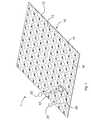
- FIG. 1is a perspective view of the flush-mount attachment system of the present invention showing a three peg array
- FIG. 2is a perspective view of the back of the board showing the T-shaped key inside the cavity;
- FIG. 3shows Detail A of FIG. 2 , wherein the T-shaped key is shown in locked and unlocked positions;
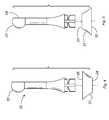
- FIG. 4is an exploded view of the peg assembly with the skirt reversed
- FIG. 5is an exploded view of the peg assembly
- FIG. 6is a perspective view of the peg
- FIG. 7is an elevation view of the peg
- FIG. 8is a section view of the peg taken along line 8 - 8 of FIG. 7 ;
- FIG. 9is a perspective view of straight end terminal feature
- FIG. 10is a partial perspective view of an upwardly-bent terminal feature
- FIG. 11is a partial perspective view of a loop terminal feature
- FIG. 12is a partial perspective view of disk terminal feature
- FIG. 13is a partial perspective view of a T-bar terminal feature
- FIG. 14is a partial perspective view of a hook terminal feature.
- FIG. 1shows the principal components of a flush-mount attachment system 1 .
- the flush-mount attachment system 1is comprised of a board 10 to which pegs 20 can be attached to hold an article 2 (not shown) there between.
- the board 10is comprised of an array of convex blisters 13 .
- the arrayis comprised of such regularity and spacing as to allow a customized layout of pegs 20 to firmly and securely grip an article, the article having a relatively larger size than the spacing.
- the board and peg systempermit the article to be mounted on a wall, for example, to display the article. Alternatively, the board and peg system can fixture the article in-place for storage or transport purposes.
- novel features of the inventioneliminate the dependence on gravity to hold the article in place.
- the convex blister 13stands in relief from a front side 11 of the board 10 .
- the blister 13is comprised of an inside surface 14 which defines a blister recess 15 .
- the blister 13 and the blister recess 15are essentially circular in cross-section.
- the blister recess 15is accessible from the front side 11 by means of a key-slot aperture 16 .
- the key-slot aperture 16has a longitudinal configuration and is placed centrally on the crown of the blister.
- the blisters 13are arrayed regularly in rows and columns.
- the peg 20is comprised of a proximal end 21 and a distal end 22 .
- the proximal end 21is comprised of a means for releasably engaging 23 .
- the means for releasably engaging 23is comprised of a T-shaped key 24 , which is inserted into the key-slot aperture 16 of the blister 13 to engage therein by means of a rotational twist.
- the T-shaped key 24is comprised of a crossbar 25 at the end of a shank 26 .
- the crossbar 25has a profile that allows passage through the key-slot aperture 16 .
- the crossbar 25further has a longitudinal extent, such that misalignment of said crossbar with the longitudinal aspect of the key-slot aperture 16 places said crossbar in an interference position with the inside surface 14 of the blister 13 .
- the shank 26is rotatable within the key-slot aperture 16 .
- the shank 26extends sufficiently into the blister 13 , when the peg 20 is seated thereon, to place the crossbar 25 in brushing contact with the inside surface 14 .
- the distal end 22 of the peg 20is comprised of a means for engaging an article 50 .
- the means for engaging an article 50is a terminal feature 60 in the configuration of a ball 51 .
- the ball 51has sufficient girth as to define a ledge 52 at the junction of the ball 51 and the distal end 22 .
- the ledge 52is useful for retaining the article 2 on the peg 20 .
- Terminal features 60additionally comprise a straight end 61 , a disk end 62 , an upwardly-bent end 63 , a flattened end 64 (not shown), a T-bar end 65 , a loop end 66 , a hook end 67 and a slotted end 68 (not shown).
- the means for bracing 30comprises a flared skirt 31 , in which a concave skirt recess 32 , in complementary configuration to the convex blister 13 , rests against or over said blister.
- the flared skirt 31bears against the front side 11 of the board 10 to form a buttress-like support for the peg 20 . Since the flared skirt 31 has a complementary circular cross-section, the buttress-like support acts in all directions. The broader the flare of the skirt, and the larger the cross-section, the greater the holding power thereby provided.
- the spacing of the pegs 20is with the spacing of the pegs 20 ; or, in other words, the granularity of the peg spacing with respect to the dimensions of the article.
- the pegs 20are spaced at intervals of 0.5 to 1.0 inches and individually hold between 30 and 60 pounds.
- the peg 20When the T-shaped key 24 is inserted in the key-slot aperture 16 of a selected blister 13 , the peg 20 is rotated to a preferred position 27 ( FIG. 3 ) where structural interference prevents it from being withdrawn there from.
- the preferred position 27is at a rotational angle of approximately 90 degrees.
- a means for reversibly locking 40inhibits further rotational movement and prevents slippage of position.
- the means for reversibly locking 40is comprised of a pair of bosses 41 positioned to straddle the T-shaped key 24 .
- the blister 13When the blister 13 is rendered resiliently flexible, a slight compression force on the blister crown frees the rotation of the T-shaped key 24 to the preferred position 27 and into abutment against the pair of bosses 41 .
- the resilient recoverythereafter pins the T-shaped key into location and between the bosses 41 .
- the two bossesare arrayed oppositely, but they may also be arrayed in tandem to box-in the T-shaped key.
- a novel feature of the present inventionprovides a means for laterally gripping 33 .
- the means for laterally gripping 33is comprised of a two-component peg 20 , wherein the flared skirt 31 can be removed and reassembled with an end-to-end reversal, as shown in FIGS. 4 and 5 . Because of the flare, one end of the flared skirt 31 is narrower than the other.
- a narrow end 34is placed against a partial surface 36 ( FIG. 1 ) of the blister 13 .
- the partial surface 36deforms the resiliently flexible blister 13 causing a tension response.
- Two pegs placed horizontally, and configured as above,would suspend an article placed there between when the spacing is such as to bias the pegs apart.
- a wide end 35 of the skirt 31provides a stand-off from the blister 13 and causes the sideways pressure to be applied at a point distant from the T-shaped key. Because the T-shaped key operates as a fulcrum in this circumstance, the stand-off results in a mechanical leverage being applied to the peg 13 .
- the wide end 35additionally functions to space the article 2 away from the board 10 .
- a means for orienting 53is comprised of a flat surface 54 on the ball 51 ( FIG. 6 ).
- the flat surface 54preferably has a surface normal in alignment with the longitudinal direction of the T-shaped key 24 .
- the flat surface 54can be any of the lesser cross-sections of ball 51 , but that cross-section in tangency with the peg is one preferred.
- the flat surface 54additionally provides a means for grasping the peg 20 and applying a twisting motion thereto. The preferred cross-section maximizes that grasp and twist leverage.
- the board 10 and the peg 20are preferably fabricated by molding technologies where precision tolerances can be met.
- the peg 20is preferably injection-molded.
- the board 10can be injection-molded or thermoformed from sheet or roll film stock.
- the key material propertiesare toughness and strength. Since flexibility is often at odds with strength, the flexibility of the blister is best served by thinning-out the wall. The property of toughness, wherein plastic deformation is sustainable, provides the requisite resiliency in combination with the architectural strength of the convex shape of the blister.
- polystyreneHIPS
- ABSacrylonitrile butadiene styrene
- PPpolypropylene
- HDPEhigh-density polyethylene
- PVCpoly-vinyl chloride
- PEpolyolefin
- a plurality of articlescan be placed in any organization on the flush-mount attachment system 1 and held securely thereon for any orientation of said system relative to gravity.
- an analysis of where dislodging forces might be brought to bear on any particular article for any particular scenariowould lead to a selection of sites for locating the pegs and to a choice between gripping or load-bearing functionality.
- a method of attaching an article to an intimate support surfacecomprises the following steps:
- a travel chess setmight be comprised by arraying the blisters in correspondence to spaces on a chess board and configuring a chess-piece-complement of pegs with terminal features representing the individual chess pieces.
- phraseology and terminology employed hereinare for the purpose of the description and should not be regarded as limiting.
Landscapes
- Engineering & Computer Science (AREA)
- Mechanical Engineering (AREA)
- Packages (AREA)
- Drawing Aids And Blackboards (AREA)
Abstract
Description
- (a.) Providing the flush-
mount system 1, as described above; - (b.) Providing a plurality of
pegs 20, wherein the means for engaging anarticle 50 is a terminal feature in the shape of aball 51; - (c.) Attaching the essentially
flat board 10 to the support surface; - (d.) Determining a first array of locations on the article2 sufficient for vertical support thereto, as appropriate;
- (e.) Determining a second array of locations on the article2 sufficient for lateral support thereto, as appropriate;
- (f.) Making a first selection of the
blisters 13 in best correspondence to the first array; - (g.) Locking pegs20 into place to the first selection with the
wide end 35 of the flaredskirt 31 assembled to contact theblister 13; - (h.) Making a second selection of the
blisters 13 in best correspondence to the second array; - (i.) Locking pegs20 into place to the second selection with the
narrow end 34 of the flaredskirt 31 assembled to contact theblister 13; and - (j.) Mounting the article2 to the resulting layout of
pegs 20, the resilient force of theblisters 13 and the engagement of theballs 51 retaining the article2 to the essentiallyflat board 10.
- (a.) Providing the flush-
Claims (17)
Priority Applications (2)
| Application Number | Priority Date | Filing Date | Title |
|---|---|---|---|
| US12/769,384US8522986B2 (en) | 2009-09-29 | 2010-04-28 | Locking pegboard |
| PCT/US2010/050551WO2011041314A2 (en) | 2009-09-29 | 2010-09-28 | Locking pegboard |
Applications Claiming Priority (2)
| Application Number | Priority Date | Filing Date | Title |
|---|---|---|---|
| US24654909P | 2009-09-29 | 2009-09-29 | |
| US12/769,384US8522986B2 (en) | 2009-09-29 | 2010-04-28 | Locking pegboard |
Publications (2)
| Publication Number | Publication Date |
|---|---|
| US20110073730A1 US20110073730A1 (en) | 2011-03-31 |
| US8522986B2true US8522986B2 (en) | 2013-09-03 |
Family
ID=43779223
Family Applications (1)
| Application Number | Title | Priority Date | Filing Date |
|---|---|---|---|
| US12/769,384Expired - Fee RelatedUS8522986B2 (en) | 2009-09-29 | 2010-04-28 | Locking pegboard |
Country Status (2)
| Country | Link |
|---|---|
| US (1) | US8522986B2 (en) |
| WO (1) | WO2011041314A2 (en) |
Cited By (14)
| Publication number | Priority date | Publication date | Assignee | Title |
|---|---|---|---|---|
| US20160341232A1 (en)* | 2015-05-19 | 2016-11-24 | Pegitz, Llc | Perforated hardboard grommet & fixture securing system |
| US10041257B2 (en)* | 2009-03-23 | 2018-08-07 | Glen-Gery Corporation | Masonry support panel and associated methods of use |
| USD838561S1 (en) | 2017-07-18 | 2019-01-22 | Jonathan D. Sill | Bottle rack |
| US10285515B1 (en)* | 2017-08-21 | 2019-05-14 | Brian Desilets | Mounting apparatus and method for use |
| US10405676B1 (en) | 2016-05-16 | 2019-09-10 | Susan Evans Underwood | Article supporting assemblies and methods |
| US20190343243A1 (en)* | 2018-05-10 | 2019-11-14 | Eric Rosenberg | Apparatus, system and method for improving decor |
| US20210369013A1 (en)* | 2018-11-13 | 2021-12-02 | Carina Wood | Integrated Display Coordination Systems |
| US11304545B2 (en)* | 2019-11-13 | 2022-04-19 | Larry Currey | Perforated board and hanger storage system |
| US20220202183A1 (en)* | 2020-12-24 | 2022-06-30 | Benjamin Jay Herman | Platform having adjustably positionable immobilizers |
| US11547516B2 (en)* | 2018-03-01 | 2023-01-10 | Markus Schaub | Holding device for holding a portable medical appliance |
| US20230064515A1 (en)* | 2018-11-13 | 2023-03-02 | Carina Wood | Integrated Display Coordination Systems |
| US20230380577A1 (en)* | 2022-05-30 | 2023-11-30 | Lindnerhof-Taktik GmbH | Carrying system for an item of equipment |
| US20240156256A1 (en)* | 2022-11-11 | 2024-05-16 | Michael Coppolino | Hanging Organizer |
| US12226891B2 (en)* | 2023-05-31 | 2025-02-18 | Toyota Motor Engineering & Manufacturing North America, Inc. | Adjustable tool holder for a gun-shaped power tool |
Families Citing this family (37)
| Publication number | Priority date | Publication date | Assignee | Title |
|---|---|---|---|---|
| US8452148B2 (en) | 2008-08-29 | 2013-05-28 | Corning Cable Systems Llc | Independently translatable modules and fiber optic equipment trays in fiber optic equipment |
| US11294136B2 (en) | 2008-08-29 | 2022-04-05 | Corning Optical Communications LLC | High density and bandwidth fiber optic apparatuses and related equipment and methods |
| EP2221932B1 (en) | 2009-02-24 | 2011-11-16 | CCS Technology Inc. | Holding device for a cable or an assembly for use with a cable |
| US8699838B2 (en) | 2009-05-14 | 2014-04-15 | Ccs Technology, Inc. | Fiber optic furcation module |
| US8538226B2 (en) | 2009-05-21 | 2013-09-17 | Corning Cable Systems Llc | Fiber optic equipment guides and rails configured with stopping position(s), and related equipment and methods |
| US9075216B2 (en) | 2009-05-21 | 2015-07-07 | Corning Cable Systems Llc | Fiber optic housings configured to accommodate fiber optic modules/cassettes and fiber optic panels, and related components and methods |
| US8712206B2 (en) | 2009-06-19 | 2014-04-29 | Corning Cable Systems Llc | High-density fiber optic modules and module housings and related equipment |
| EP2443497B1 (en) | 2009-06-19 | 2020-03-04 | Corning Cable Systems LLC | High density and bandwidth fiber optic apparatus |
| US8625950B2 (en) | 2009-12-18 | 2014-01-07 | Corning Cable Systems Llc | Rotary locking apparatus for fiber optic equipment trays and related methods |
| US8992099B2 (en) | 2010-02-04 | 2015-03-31 | Corning Cable Systems Llc | Optical interface cards, assemblies, and related methods, suited for installation and use in antenna system equipment |
| US8913866B2 (en) | 2010-03-26 | 2014-12-16 | Corning Cable Systems Llc | Movable adapter panel |
| CA2796221C (en) | 2010-04-16 | 2018-02-13 | Ccs Technology, Inc. | Sealing and strain relief device for data cables |
| EP2381284B1 (en) | 2010-04-23 | 2014-12-31 | CCS Technology Inc. | Under floor fiber optic distribution device |
| US9720195B2 (en) | 2010-04-30 | 2017-08-01 | Corning Optical Communications LLC | Apparatuses and related components and methods for attachment and release of fiber optic housings to and from an equipment rack |
| US9632270B2 (en) | 2010-04-30 | 2017-04-25 | Corning Optical Communications LLC | Fiber optic housings configured for tool-less assembly, and related components and methods |
| US9519118B2 (en) | 2010-04-30 | 2016-12-13 | Corning Optical Communications LLC | Removable fiber management sections for fiber optic housings, and related components and methods |
| US8879881B2 (en)* | 2010-04-30 | 2014-11-04 | Corning Cable Systems Llc | Rotatable routing guide and assembly |
| US9075217B2 (en) | 2010-04-30 | 2015-07-07 | Corning Cable Systems Llc | Apparatuses and related components and methods for expanding capacity of fiber optic housings |
| US8705926B2 (en) | 2010-04-30 | 2014-04-22 | Corning Optical Communications LLC | Fiber optic housings having a removable top, and related components and methods |
| US8660397B2 (en) | 2010-04-30 | 2014-02-25 | Corning Cable Systems Llc | Multi-layer module |
| US8718436B2 (en) | 2010-08-30 | 2014-05-06 | Corning Cable Systems Llc | Methods, apparatuses for providing secure fiber optic connections |
| US9279951B2 (en) | 2010-10-27 | 2016-03-08 | Corning Cable Systems Llc | Fiber optic module for limited space applications having a partially sealed module sub-assembly |
| US9116324B2 (en) | 2010-10-29 | 2015-08-25 | Corning Cable Systems Llc | Stacked fiber optic modules and fiber optic equipment configured to support stacked fiber optic modules |
| US8662760B2 (en) | 2010-10-29 | 2014-03-04 | Corning Cable Systems Llc | Fiber optic connector employing optical fiber guide member |
| CA2819235C (en) | 2010-11-30 | 2018-01-16 | Corning Cable Systems Llc | Fiber device holder and strain relief device |
| WO2012106510A2 (en) | 2011-02-02 | 2012-08-09 | Corning Cable Systems Llc | Dense fiber optic connector assemblies and related connectors and cables suitable for establishing optical connections for optical backplanes in equipment racks |
| US9008485B2 (en) | 2011-05-09 | 2015-04-14 | Corning Cable Systems Llc | Attachment mechanisms employed to attach a rear housing section to a fiber optic housing, and related assemblies and methods |
| AU2012275598A1 (en) | 2011-06-30 | 2014-01-16 | Corning Optical Communications LLC | Fiber optic equipment assemblies employing non-U-width-sized housings and related methods |
| US8953924B2 (en) | 2011-09-02 | 2015-02-10 | Corning Cable Systems Llc | Removable strain relief brackets for securing fiber optic cables and/or optical fibers to fiber optic equipment, and related assemblies and methods |
| US9038832B2 (en) | 2011-11-30 | 2015-05-26 | Corning Cable Systems Llc | Adapter panel support assembly |
| US9250409B2 (en) | 2012-07-02 | 2016-02-02 | Corning Cable Systems Llc | Fiber-optic-module trays and drawers for fiber-optic equipment |
| US9042702B2 (en) | 2012-09-18 | 2015-05-26 | Corning Cable Systems Llc | Platforms and systems for fiber optic cable attachment |
| ES2551077T3 (en) | 2012-10-26 | 2015-11-16 | Ccs Technology, Inc. | Fiber optic management unit and fiber optic distribution device |
| US8985862B2 (en) | 2013-02-28 | 2015-03-24 | Corning Cable Systems Llc | High-density multi-fiber adapter housings |
| CN105114793A (en)* | 2015-09-25 | 2015-12-02 | 深圳市大疆创新科技有限公司 | Support |
| US10932593B2 (en)* | 2018-08-30 | 2021-03-02 | Edsal Manufacturing Company, Inc. | Organizer set with retention system and method of making same |
| US11369216B2 (en)* | 2020-05-25 | 2022-06-28 | Ihab Fleega | Holder for personal items |
Citations (37)
| Publication number | Priority date | Publication date | Assignee | Title |
|---|---|---|---|---|
| US2715A (en) | 1842-07-11 | fowler | ||
| US423730A (en)* | 1890-03-18 | William b | ||
| US478025A (en)* | 1892-06-28 | sohrxudnee | ||
| US483841A (en)* | 1892-10-04 | Device for detachable securing desks | ||
| US1202503A (en) | 1916-03-06 | 1916-10-24 | Edward Fortier | Clothes-line hook. |
| US1637047A (en) | 1926-03-13 | 1927-07-26 | Moore Benjamin Franklin | Swinging hook |
| US1846412A (en)* | 1929-12-12 | 1932-02-23 | Weinberg Alexander | Game apparatus |
| US2260048A (en)* | 1939-12-27 | 1941-10-21 | Gen Electric | Fastening arrangement |
| US3179367A (en)* | 1963-04-11 | 1965-04-20 | Illinois Tool Works | Plastic quarter turn shelf support |
| US3185427A (en)* | 1963-03-22 | 1965-05-25 | Renault | Two-position supporting pegs made of flexible material, more particularly for use in motor vehicles |
| US3191777A (en)* | 1964-04-20 | 1965-06-29 | Jr George W Willits | Flexible, perforated display or storage panels |
| US3216584A (en)* | 1963-06-25 | 1965-11-09 | M & D Store Fixtures Inc | Hanger base |
| US3255987A (en) | 1965-04-28 | 1966-06-14 | Lewis Co G B | Adjustable plastic pin support |
| US3310271A (en)* | 1965-10-15 | 1967-03-21 | Leonard H King | Apertured display board and hardware therefor |
| US3322287A (en)* | 1966-06-01 | 1967-05-30 | Selfix Inc | Flexible apertured panels |
| US3407454A (en)* | 1966-04-23 | 1968-10-29 | Keith E. Myatt | Quick release fasteners |
| US3443783A (en)* | 1966-12-14 | 1969-05-13 | Illinois Tool Works | Plastic fastener |
| US3688635A (en)* | 1971-03-04 | 1972-09-05 | Richco Plastic Co | Circuit board support |
| US3724792A (en)* | 1970-08-10 | 1973-04-03 | D Thalenfeld | Apertured panel hook and method for manufacture |
| US3800369A (en)* | 1972-09-01 | 1974-04-02 | Ford Motor Co | Fastener flash molded integral with parent part |
| US3880390A (en)* | 1973-11-08 | 1975-04-29 | Dynagraphic Merchandising Corp | Universal pegboard |
| US4223861A (en)* | 1977-12-02 | 1980-09-23 | Sterner Lighting Systems Incorporated | Adjustable hanger for elongated wall mounted members |
| US4264013A (en)* | 1979-04-12 | 1981-04-28 | Vollmer Mary C | Jewelry holder |
| US4372450A (en)* | 1981-12-07 | 1983-02-08 | Basic Line, Inc. | Hanging racks |
| US4493580A (en)* | 1982-06-24 | 1985-01-15 | Illinois Tool Works, Inc. | Retaining prong |
| US4527760A (en) | 1983-06-29 | 1985-07-09 | Super Glue Corporation | Adjustable clip system |
| US4805784A (en) | 1988-01-14 | 1989-02-21 | Karsten Manufacturing Corporation | Slatwall mounting device |
| US4884688A (en)* | 1988-04-11 | 1989-12-05 | Hurst Joseph S | Tooth brush case |
| USD355112S (en)* | 1989-08-28 | 1995-02-07 | Richeson James R | Pegboard hook |
| US5927517A (en)* | 1998-02-18 | 1999-07-27 | Lipman; Daniel | Merchandising display assembly |
| US6481584B1 (en)* | 1999-08-16 | 2002-11-19 | Richard W. Cantley | Plastic pegboard |
| WO2004026084A1 (en) | 2002-09-19 | 2004-04-01 | Lee Carl Mccormack | Support system |
| US6896228B1 (en)* | 2003-04-24 | 2005-05-24 | Tung Hsien Lu | Fixing device for a bath support rack |
| US7051984B2 (en)* | 2003-01-24 | 2006-05-30 | Botkin Kirk J | Assembly for supporting and displaying objects |
| US20060124812A1 (en) | 2002-10-23 | 2006-06-15 | Philip Berardi | Support extension for stage apparatus |
| US20060243687A1 (en)* | 2005-04-27 | 2006-11-02 | Hilger John K | Peg board tool organizer |
| US20070015403A1 (en)* | 2005-07-12 | 2007-01-18 | Radiall | Electrical connection assembly |
Family Cites Families (4)
| Publication number | Priority date | Publication date | Assignee | Title |
|---|---|---|---|---|
| US5881982A (en)* | 1993-03-12 | 1999-03-16 | Hollingsworth; Don A. | Fastener for holding objects to a perforated wall |
| US5490650A (en)* | 1994-09-14 | 1996-02-13 | Pendergrass; Frank | Combined hanging apparatus and pegboard and method for installing a hanging apparatus on a pegboard |
| US5855347A (en)* | 1996-07-18 | 1999-01-05 | Hollingsworth; Don A. | Fastener for holding items to a perforated wall |
| US7481406B2 (en)* | 2006-06-20 | 2009-01-27 | Newell Operating Company | Plastic pegboard assembly |
- 2010
- 2010-04-28USUS12/769,384patent/US8522986B2/ennot_activeExpired - Fee Related
- 2010-09-28WOPCT/US2010/050551patent/WO2011041314A2/enactiveApplication Filing
Patent Citations (38)
| Publication number | Priority date | Publication date | Assignee | Title |
|---|---|---|---|---|
| US423730A (en)* | 1890-03-18 | William b | ||
| US478025A (en)* | 1892-06-28 | sohrxudnee | ||
| US483841A (en)* | 1892-10-04 | Device for detachable securing desks | ||
| US2715A (en) | 1842-07-11 | fowler | ||
| US1202503A (en) | 1916-03-06 | 1916-10-24 | Edward Fortier | Clothes-line hook. |
| US1637047A (en) | 1926-03-13 | 1927-07-26 | Moore Benjamin Franklin | Swinging hook |
| US1846412A (en)* | 1929-12-12 | 1932-02-23 | Weinberg Alexander | Game apparatus |
| US2260048A (en)* | 1939-12-27 | 1941-10-21 | Gen Electric | Fastening arrangement |
| US3185427A (en)* | 1963-03-22 | 1965-05-25 | Renault | Two-position supporting pegs made of flexible material, more particularly for use in motor vehicles |
| US3179367A (en)* | 1963-04-11 | 1965-04-20 | Illinois Tool Works | Plastic quarter turn shelf support |
| US3216584A (en)* | 1963-06-25 | 1965-11-09 | M & D Store Fixtures Inc | Hanger base |
| US3191777A (en)* | 1964-04-20 | 1965-06-29 | Jr George W Willits | Flexible, perforated display or storage panels |
| US3255987A (en) | 1965-04-28 | 1966-06-14 | Lewis Co G B | Adjustable plastic pin support |
| US3310271A (en)* | 1965-10-15 | 1967-03-21 | Leonard H King | Apertured display board and hardware therefor |
| US3407454A (en)* | 1966-04-23 | 1968-10-29 | Keith E. Myatt | Quick release fasteners |
| US3322287A (en)* | 1966-06-01 | 1967-05-30 | Selfix Inc | Flexible apertured panels |
| US3443783A (en)* | 1966-12-14 | 1969-05-13 | Illinois Tool Works | Plastic fastener |
| US3724792A (en)* | 1970-08-10 | 1973-04-03 | D Thalenfeld | Apertured panel hook and method for manufacture |
| US3688635A (en)* | 1971-03-04 | 1972-09-05 | Richco Plastic Co | Circuit board support |
| US3800369A (en)* | 1972-09-01 | 1974-04-02 | Ford Motor Co | Fastener flash molded integral with parent part |
| US3880390A (en)* | 1973-11-08 | 1975-04-29 | Dynagraphic Merchandising Corp | Universal pegboard |
| US4223861A (en)* | 1977-12-02 | 1980-09-23 | Sterner Lighting Systems Incorporated | Adjustable hanger for elongated wall mounted members |
| US4264013A (en)* | 1979-04-12 | 1981-04-28 | Vollmer Mary C | Jewelry holder |
| US4372450A (en)* | 1981-12-07 | 1983-02-08 | Basic Line, Inc. | Hanging racks |
| US4493580A (en)* | 1982-06-24 | 1985-01-15 | Illinois Tool Works, Inc. | Retaining prong |
| US4527760A (en) | 1983-06-29 | 1985-07-09 | Super Glue Corporation | Adjustable clip system |
| US4805784A (en) | 1988-01-14 | 1989-02-21 | Karsten Manufacturing Corporation | Slatwall mounting device |
| US4884688A (en)* | 1988-04-11 | 1989-12-05 | Hurst Joseph S | Tooth brush case |
| USD355112S (en)* | 1989-08-28 | 1995-02-07 | Richeson James R | Pegboard hook |
| US5927517A (en)* | 1998-02-18 | 1999-07-27 | Lipman; Daniel | Merchandising display assembly |
| US6481584B1 (en)* | 1999-08-16 | 2002-11-19 | Richard W. Cantley | Plastic pegboard |
| WO2004026084A1 (en) | 2002-09-19 | 2004-04-01 | Lee Carl Mccormack | Support system |
| US20060124812A1 (en) | 2002-10-23 | 2006-06-15 | Philip Berardi | Support extension for stage apparatus |
| US7051984B2 (en)* | 2003-01-24 | 2006-05-30 | Botkin Kirk J | Assembly for supporting and displaying objects |
| US6896228B1 (en)* | 2003-04-24 | 2005-05-24 | Tung Hsien Lu | Fixing device for a bath support rack |
| US20060243687A1 (en)* | 2005-04-27 | 2006-11-02 | Hilger John K | Peg board tool organizer |
| US20070015403A1 (en)* | 2005-07-12 | 2007-01-18 | Radiall | Electrical connection assembly |
| US7357669B2 (en)* | 2005-07-12 | 2008-04-15 | Radiall | Electrical connection assembly |
Cited By (19)
| Publication number | Priority date | Publication date | Assignee | Title |
|---|---|---|---|---|
| US10041257B2 (en)* | 2009-03-23 | 2018-08-07 | Glen-Gery Corporation | Masonry support panel and associated methods of use |
| US10087978B2 (en)* | 2015-05-19 | 2018-10-02 | Pegitz, Llc | Perforated hardboard grommet and fixture securing system |
| US20160341232A1 (en)* | 2015-05-19 | 2016-11-24 | Pegitz, Llc | Perforated hardboard grommet & fixture securing system |
| US10405676B1 (en) | 2016-05-16 | 2019-09-10 | Susan Evans Underwood | Article supporting assemblies and methods |
| USD838561S1 (en) | 2017-07-18 | 2019-01-22 | Jonathan D. Sill | Bottle rack |
| US10285515B1 (en)* | 2017-08-21 | 2019-05-14 | Brian Desilets | Mounting apparatus and method for use |
| US11547516B2 (en)* | 2018-03-01 | 2023-01-10 | Markus Schaub | Holding device for holding a portable medical appliance |
| US20190343243A1 (en)* | 2018-05-10 | 2019-11-14 | Eric Rosenberg | Apparatus, system and method for improving decor |
| US20230064515A1 (en)* | 2018-11-13 | 2023-03-02 | Carina Wood | Integrated Display Coordination Systems |
| US11510508B2 (en)* | 2018-11-13 | 2022-11-29 | Carina Wood | Integrated display coordination systems |
| US20210369013A1 (en)* | 2018-11-13 | 2021-12-02 | Carina Wood | Integrated Display Coordination Systems |
| US11304545B2 (en)* | 2019-11-13 | 2022-04-19 | Larry Currey | Perforated board and hanger storage system |
| US20220202183A1 (en)* | 2020-12-24 | 2022-06-30 | Benjamin Jay Herman | Platform having adjustably positionable immobilizers |
| US12029316B2 (en)* | 2020-12-24 | 2024-07-09 | Benjamin Jay Herman | Platform having adjustably positionable immobilizers |
| USD1082868S1 (en)* | 2020-12-24 | 2025-07-08 | Benjamin Jay Herman | Peg |
| US20230380577A1 (en)* | 2022-05-30 | 2023-11-30 | Lindnerhof-Taktik GmbH | Carrying system for an item of equipment |
| US20240156256A1 (en)* | 2022-11-11 | 2024-05-16 | Michael Coppolino | Hanging Organizer |
| US12364329B2 (en)* | 2022-11-11 | 2025-07-22 | Copps Enterprise Inc. | Hanging organizer |
| US12226891B2 (en)* | 2023-05-31 | 2025-02-18 | Toyota Motor Engineering & Manufacturing North America, Inc. | Adjustable tool holder for a gun-shaped power tool |
Also Published As
| Publication number | Publication date |
|---|---|
| US20110073730A1 (en) | 2011-03-31 |
| WO2011041314A3 (en) | 2011-07-28 |
| WO2011041314A2 (en) | 2011-04-07 |
Similar Documents
| Publication | Publication Date | Title |
|---|---|---|
| US8522986B2 (en) | Locking pegboard | |
| US8020328B2 (en) | Connecting elements for construction | |
| CN101652089B (en) | Storage and organization system | |
| US5176465A (en) | Device for interlocking separate component housing structures | |
| US6276644B1 (en) | Compact cable anchor for retainment and attachment of cables and tubing | |
| US8096517B1 (en) | Steering wheel laptop computer holder | |
| US11109679B2 (en) | Shelving assembly and hardware | |
| KR101826610B1 (en) | wall type storage device | |
| US20160265715A1 (en) | Safety securing apparatus | |
| JP4764315B2 (en) | Assembly furniture | |
| US7665619B2 (en) | Modular shelf system | |
| HU216886B (en) | Building toy system and tool to equip the building elements with connection elements | |
| US20120234505A1 (en) | Garage door storage space utilizer | |
| CN102912859B (en) | Connector with a locking member | |
| US20240018988A1 (en) | Anchorable clip / wiring harness | |
| US20180352954A1 (en) | Wall Storage System | |
| US20070090067A1 (en) | Lattice merchandise display system | |
| US8967571B2 (en) | Plate having a back side adapted to be secured to a base and a front side adapted for attaching various items | |
| JP6377092B2 (en) | Article support device | |
| JP7385255B2 (en) | Gypsum board base and article mounting structure | |
| JP3164643U (en) | Product display | |
| JP6466064B2 (en) | Furniture fall prevention structure | |
| JP5503840B2 (en) | Member mounting structure and fixture | |
| JP4441097B2 (en) | Mounting structure for the rear panel of the table top | |
| WO2020077458A1 (en) | Anchorable clip / wiring harness |
Legal Events
| Date | Code | Title | Description |
|---|---|---|---|
| STCF | Information on status: patent grant | Free format text:PATENTED CASE | |
| AS | Assignment | Owner name:PEG LOCK LLC, VIRGINIA Free format text:ASSIGNMENT OF ASSIGNORS INTEREST;ASSIGNOR:KITCHEN, MICHAEL BRENT;REEL/FRAME:036684/0906 Effective date:20140609 | |
| AS | Assignment | Owner name:PEGLOCK, INC., VIRGINIA Free format text:CORRECTIVE ASSIGNMENT TO CORRECT THE ASSIGNEE NAME PREVIOUSLY RECORDED AT REEL: 036684 FRAME: 0906. ASSIGNOR(S) HEREBY CONFIRMS THE ASSIGNMENT;ASSIGNOR:KITCHEN, MICHAEL BRENT;REEL/FRAME:037486/0048 Effective date:20140609 | |
| AS | Assignment | Owner name:PEGLOCK, INC., VIRGINIA Free format text:CORRECTIVE ASSIGNMENT TO CORRECT THE ASSIGNEE ADDRESS PREVIOUSLY RECORDED AT REEL: 037486 FRAME: 0048. ASSIGNOR(S) HEREBY CONFIRMS THE ASSIGNMENT;ASSIGNOR:KITCHEN, MICHAEL BRENT;REEL/FRAME:037565/0863 Effective date:20140609 | |
| REMI | Maintenance fee reminder mailed | ||
| FEPP | Fee payment procedure | Free format text:SURCHARGE FOR LATE PAYMENT, SMALL ENTITY (ORIGINAL EVENT CODE: M2554) | |
| MAFP | Maintenance fee payment | Free format text:PAYMENT OF MAINTENANCE FEE, 4TH YR, SMALL ENTITY (ORIGINAL EVENT CODE: M2551) Year of fee payment:4 | |
| MAFP | Maintenance fee payment | Free format text:PAYMENT OF MAINTENANCE FEE, 8TH YR, SMALL ENTITY (ORIGINAL EVENT CODE: M2552); ENTITY STATUS OF PATENT OWNER: SMALL ENTITY Year of fee payment:8 | |
| FEPP | Fee payment procedure | Free format text:MAINTENANCE FEE REMINDER MAILED (ORIGINAL EVENT CODE: REM.); ENTITY STATUS OF PATENT OWNER: SMALL ENTITY | |
| LAPS | Lapse for failure to pay maintenance fees | Free format text:PATENT EXPIRED FOR FAILURE TO PAY MAINTENANCE FEES (ORIGINAL EVENT CODE: EXP.); ENTITY STATUS OF PATENT OWNER: SMALL ENTITY | |
| STCH | Information on status: patent discontinuation | Free format text:PATENT EXPIRED DUE TO NONPAYMENT OF MAINTENANCE FEES UNDER 37 CFR 1.362 |