US8521384B2 - Turf maintenance vehicle all-wheel drive system - Google Patents
Turf maintenance vehicle all-wheel drive systemDownload PDFInfo
- Publication number
- US8521384B2 US8521384B2US12/360,410US36041009AUS8521384B2US 8521384 B2US8521384 B2US 8521384B2US 36041009 AUS36041009 AUS 36041009AUS 8521384 B2US8521384 B2US 8521384B2
- Authority
- US
- United States
- Prior art keywords
- motor
- wheel
- traction control
- maintenance vehicle
- control system
- Prior art date
- Legal status (The legal status is an assumption and is not a legal conclusion. Google has not performed a legal analysis and makes no representation as to the accuracy of the status listed.)
- Active, expires
Links
- 238000012423maintenanceMethods0.000titleclaimsabstractdescription61
- 230000001133accelerationEffects0.000claimsdescription15
- 238000004891communicationMethods0.000claimsdescription9
- 230000003247decreasing effectEffects0.000claimsdescription8
- 230000007423decreaseEffects0.000claimsdescription6
- 230000004044responseEffects0.000claimsdescription6
- KSWHNTPMGZKIOB-UHFFFAOYSA-N5-hexyl-2-(2-methylphenoxy)phenolChemical compoundOC1=CC(CCCCCC)=CC=C1OC1=CC=CC=C1CKSWHNTPMGZKIOB-UHFFFAOYSA-N0.000description29
- 238000012546transferMethods0.000description14
- 230000007935neutral effectEffects0.000description4
- 244000025254Cannabis sativaSpecies0.000description3
- 230000008901benefitEffects0.000description3
- 230000033001locomotionEffects0.000description3
- CRQQGFGUEAVUIL-UHFFFAOYSA-NchlorothalonilChemical compoundClC1=C(Cl)C(C#N)=C(Cl)C(C#N)=C1ClCRQQGFGUEAVUIL-UHFFFAOYSA-N0.000description2
- 239000000446fuelSubstances0.000description2
- 230000009118appropriate responseEffects0.000description1
- 230000000712assemblyEffects0.000description1
- 238000000429assemblyMethods0.000description1
- 239000003990capacitorSubstances0.000description1
- 238000010586diagramMethods0.000description1
- 238000006073displacement reactionMethods0.000description1
- 238000004146energy storageMethods0.000description1
- 239000002828fuel tankSubstances0.000description1
- 239000003502gasolineSubstances0.000description1
- 235000021384green leafy vegetablesNutrition0.000description1
- 238000000034methodMethods0.000description1
- 238000012544monitoring processMethods0.000description1
- 230000008054signal transmissionEffects0.000description1
- 238000003466weldingMethods0.000description1
Images


Classifications
- A—HUMAN NECESSITIES
- A01—AGRICULTURE; FORESTRY; ANIMAL HUSBANDRY; HUNTING; TRAPPING; FISHING
- A01D—HARVESTING; MOWING
- A01D69/00—Driving mechanisms or parts thereof for harvesters or mowers
- A01D69/02—Driving mechanisms or parts thereof for harvesters or mowers electric
- A—HUMAN NECESSITIES
- A01—AGRICULTURE; FORESTRY; ANIMAL HUSBANDRY; HUNTING; TRAPPING; FISHING
- A01D—HARVESTING; MOWING
- A01D34/00—Mowers; Mowing apparatus of harvesters
- A01D34/006—Control or measuring arrangements
- A—HUMAN NECESSITIES
- A01—AGRICULTURE; FORESTRY; ANIMAL HUSBANDRY; HUNTING; TRAPPING; FISHING
- A01D—HARVESTING; MOWING
- A01D34/00—Mowers; Mowing apparatus of harvesters
- A01D34/01—Mowers; Mowing apparatus of harvesters characterised by features relating to the type of cutting apparatus
- A01D34/412—Mowers; Mowing apparatus of harvesters characterised by features relating to the type of cutting apparatus having rotating cutters
- A01D34/42—Mowers; Mowing apparatus of harvesters characterised by features relating to the type of cutting apparatus having rotating cutters having cutters rotating about a horizontal axis, e.g. cutting-cylinders
- A01D34/43—Mowers; Mowing apparatus of harvesters characterised by features relating to the type of cutting apparatus having rotating cutters having cutters rotating about a horizontal axis, e.g. cutting-cylinders mounted on a vehicle, e.g. a tractor, or drawn by an animal or a vehicle
- A01D34/44—Mowers; Mowing apparatus of harvesters characterised by features relating to the type of cutting apparatus having rotating cutters having cutters rotating about a horizontal axis, e.g. cutting-cylinders mounted on a vehicle, e.g. a tractor, or drawn by an animal or a vehicle with two or more cutters
- A—HUMAN NECESSITIES
- A01—AGRICULTURE; FORESTRY; ANIMAL HUSBANDRY; HUNTING; TRAPPING; FISHING
- A01G—HORTICULTURE; CULTIVATION OF VEGETABLES, FLOWERS, RICE, FRUIT, VINES, HOPS OR SEAWEED; FORESTRY; WATERING
- A01G20/00—Cultivation of turf, lawn or the like; Apparatus or methods therefor
- A01G20/30—Apparatus for treating the lawn or grass surface
- Y—GENERAL TAGGING OF NEW TECHNOLOGICAL DEVELOPMENTS; GENERAL TAGGING OF CROSS-SECTIONAL TECHNOLOGIES SPANNING OVER SEVERAL SECTIONS OF THE IPC; TECHNICAL SUBJECTS COVERED BY FORMER USPC CROSS-REFERENCE ART COLLECTIONS [XRACs] AND DIGESTS
- Y02—TECHNOLOGIES OR APPLICATIONS FOR MITIGATION OR ADAPTATION AGAINST CLIMATE CHANGE
- Y02T—CLIMATE CHANGE MITIGATION TECHNOLOGIES RELATED TO TRANSPORTATION
- Y02T10/00—Road transport of goods or passengers
- Y02T10/60—Other road transportation technologies with climate change mitigation effect
- Y02T10/72—Electric energy management in electromobility
Definitions
- the present disclosurerelates to a drive system for and method for operating a turf maintenance system vehicle.
- Wheeled turf maintenance vehiclesare commonly used to cut fairway grass or lawns, and more precisely maintain grass height of golf course greens. At least one wheel is normally powered by a power unit such as an engine or battery pack associated with the turf maintenance vehicle. The powered wheel or wheels can slip under certain circumstances which can cause damage to the turf.
- an all-wheel drive traction control system for a turf maintenance vehicleincludes at least one primary wheel operating to propel the turf maintenance vehicle.
- a first motoroperates to rotate the primary wheel.
- a traction control systemis in communication with the first motor.
- At least one secondary wheelis operable to steer the turf maintenance vehicle.
- a second motoris energized to rotate the secondary wheel.
- a current flow to at least one of the first motoris temporarily decreased and the second motor is temporarily increased by the traction control system in response to a wheel slip condition of the primary wheel.
- a speed threshold limitis stored in the traction control system.
- the speed threshold limitis exceeded when compared to the first signal by a predetermined value, the traction control system generates a slippage occurrence message indicative of a slip event of the primary wheel.
- an all-wheel drive traction control system for a turf maintenance vehicleincludes at least one continuously-driven primary wheel operating to propel the turf maintenance vehicle.
- a first motoroperates to rotate the primary wheel.
- a traction control systemhas a first portion in communication with the first motor, the traction control system operating to monitor a first signal.
- At least one secondary wheelis operable to steer the turf maintenance vehicle.
- a second motoris energized to rotate the secondary wheel.
- a second portion of the traction control systemoperating to monitor a steering angle value of the secondary wheel and a second signal.
- a speed threshold limitis stored in the traction control system.
- the traction control systemoperably compares the first signal to the speed threshold limit and when the speed threshold limit is exceeded by a predetermined amount a slippage occurrence message indicative of a slip event of the primary wheel is generated. At least one of a current to the first motor is operably decreased and a current to the second motor is operably increased during the slip event.
- the all-wheel drive traction control systemcan further include a first signal from the first motor monitored by the traction control system.
- a steering angle value of the secondary wheelcan operate as an input to the traction control system.
- a predetermined speed threshold limitcan be saved in the traction control system.
- the traction control systemis operable to compare the first signal to the predetermined speed threshold limit to determine occurrence of the wheel slip condition of the primary wheel.
- the traction control systemis operable to perform at least one of increasing the current to the second motor and decreasing the current to the first motor to recover from the wheel slip condition.
- a second signal from the second motorcan be monitored by the traction control system.
- the traction control systemis operable to compare the first signal to the second signal to determine occurrence of the wheel slip condition of the primary wheel.
- the traction control systemis operable to perform at least one of increasing the current to the second motor and decreasing the current to the first motor to recover from the wheel slip condition.
- an all-wheel drive traction control system for a turf maintenance vehiclecan include at least one continuously-driven primary wheel operating to propel the turf maintenance vehicle, and a first motor operating to rotate the primary wheel, a traction control system having a first portion in communication with the first motor, the traction control system operating to monitor a first signal. At least one secondary wheel is operable to steer the turf maintenance vehicle. A second motor is energized to rotate the secondary wheel. A second portion of the traction control system operates to monitor a steering angle value of the secondary wheel and a second signal. A speed threshold limit can be stored in the traction control system.
- the traction control systemis operable to compare the first signal to the speed threshold limit and when the speed threshold limit is exceeded by a predetermined amount a slippage occurrence message indicative of a slip event of the primary wheel is generated.
- the traction control systemis operable to perform at least one of increasing the current to the second motor and decreasing the current to the first motor during the slip event.
- the all-wheel drive traction control systemcan further include a power steering control unit operating to control steering motion of the secondary wheel and to receive the steering angle value.
- a steering control motorin electrical communication with the power steering control unit and mechanically connected to the secondary wheel is operative to receive a steering control signal from the power steering control unit and to physically direct the steering motion of the secondary wheel.
- a throttle control systemin communication with the traction control system can operate to advance or retard an operating speed of the first motor.
- a generator setcan operate to create an electrical power transferable through a vehicle bus to energize the first and second motors and the traction control system. The current to the second motor decreases as the steering angle value decreases to a null position, and increases as the steering angle value increases with respect to the null position.
- the at least one primary wheelcomprises first and second driven wheels rotatably connected to the first motor by a differential.
- the first signalcan be a first motor current demand.
- the first signalcan also be an acceleration rate of the first motor.
- the second signalcan be a second motor current demand.
- the second signalcan also be an acceleration rate of the second motor.
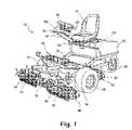
- FIG. 1is a perspective view of a turf maintenance vehicle having an all-wheel drive system
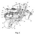
- FIG. 2is a side elevational perspective view of the turf maintenance vehicle of FIG. 1 with a power unit cover removed for clarity;
- FIG. 3is a rear perspective view of the turf maintenance vehicle of FIG. 1 showing a motor/generator power unit installed together with a steerable wheel drive motor;
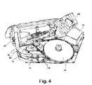
- FIG. 4is the rear perspective view of the turf maintenance vehicle of FIG. 3 with the power unit removed for clarity;
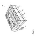
- FIG. 5is a perspective view of a modular power source including a plurality of batteries creating a battery unit
- FIG. 6is a diagram of the all-wheel drive system components of the present disclosure.
- FIG. 7is a perspective assembly view of the frame and front drive train of the turf maintenance vehicle of the present disclosure.
- FIG. 8is a rear portion of the perspective assembly view of FIG. 7 further including power steering and control features of the all-wheel drive system.
- a turf maintenance vehicle 10in a first configuration includes a frame 12 supporting a seat 14 operable to support an operator, a steering device 16 such as a steering wheel, and a plurality of cutting units 18 , 20 , 22 supported by frame 12 .
- Cutting units 18 , 20 , 22are shown as reel blade units, however the cutting units can be other types including rotary cutting units, or may be any type of implements operated during turf care operations, including, by way of example, cutting units, rakes, groomers, and the like.
- Primary, or first and second drive wheels 24 , 26 used to propel turf maintenance vehicle 10are connected to frame 12 .
- Secondary or steerable wheel 28 used to both propel and steer turf maintenance vehicle 10are also connected to frame 12 .
- two or more secondary or steerable wheels 28can be provided.
- a power unit 30is connected to frame 12 which can be provided with a cover 32 .
- Power unit 30provides power to rotate first and second drive wheels 24 , 26 via at least one axle shaft 34 .
- a throttle control device 36which can be actuated by a foot controlled pedal is provided to control a forward or reverse speed or to stop turf maintenance vehicle 10 .
- Power unit 30can be electrically coupled to each of a plurality of electric motors 38 , 40 , 42 each connected to one of the plurality of first, second and third cutting units 18 , 20 , 22 .
- Electric motors 38 , 40 , 42provide the rotating drive force to operate a plurality of first, second and third reel blade assemblies 44 , 46 , 48 rotatably mounted to individual ones of first, second and third cutting units 18 , 20 , 22 (third reel blade assembly 48 of third cutting unit 22 is not clearly visible in this view).
- first, second and third cutting units 18 , 20 , 22can be rotary blade cutting units.
- a support arm 50can be connected to frame 12 to provide a support member 52 for mounting steering device 16 .
- Support member 52can be adjustably supported from support arm 50 to allow operator adjustment of the position of steering device 16 .
- a control unit 54can be mounted on support arm 50 proximate to seat 14 .
- Control unit 54can provide a plurality of switches 56 to assist the operator in selecting operating parameters of turf maintenance vehicle 10 such as grass cutting height, reel blade assembly or rotary blade rotating speed, and operation of items such as lights.
- a power bus 58distributes electrical power throughout turf maintenance vehicle 10 from power unit 30 .
- frame 12further includes a frame first member 60 and a frame second member 62 .
- a power unit support member 64is connectable between frame first and second members 60 , 62 .
- Power unit support member 64supports power unit 30 which in one aspect of the disclosure is an engine 65 having a reciprocating engine 66 such as a gasoline or a diesel engine, or a rotary engine.
- Engine 65provides rotating power to drive a generator 68 to generate electrical power.
- an output voltage of approximately 48 Volts DCis provided by generator 68 .
- a drive unit 70can be separately supported from power unit support member 64 , and receives electrical power from power unit 30 .
- drive unit 70is an electric steering motor which is electrically connectable to steering device 16 and rotates steerable wheel 28 in response to a specific rotation angle of steering device 16 .
- a chain 72 driven by drive unit 70can also be used to rotate a gear assembly 74 to rotate steerable wheel 28 when drive unit 70 receives electrical steering signals from steering device 16 .
- Drive unit 70 and gear assembly 74can be separately supported to frame 12 from first power unit support member 64 to allow maintenance of the components of power unit 30 without removal of drive unit 70 or gear assembly 74 .
- drive unit 70can be replaced with a mechanical or linkage drive system (not shown). Determination of the specific rotation angle of steering device 16 can still be obtained from an electric signal generated by one or more sensors connected to the mechanical or linkage drive system.
- the mechanical or linkage drive systemis connected to steerable wheel 28 in these embodiments.
- Gear assembly 74can be eliminated in these embodiments unless it is desirable to provide increased operating torque to turn steerable wheel 28 .
- Turf maintenance vehicle 10can also include a foot support structure 76 , which supports throttle control device 36 having in several embodiments an accelerator pedal 77 and a brake pedal 78 acting as a brake and/or parking brake pedal.
- a differential 79is coupled to axle shaft 34 to rotatably drive first and second drive wheels 24 , 26 .
- a first electric motor 80is coupled to differential 79 . Rotation of a shaft (not shown) of first electric motor 80 provides the drive input to differential 79 .
- Power unit 30provides electrical power to all the electrically operated equipment of turf maintenance vehicle 10 including first, second and third electric motors 38 , 40 , 42 , control unit 54 , steering device 16 , throttle control device 36 , first electric motor 80 , and to one or more headlights 81 via a wiring harness 82 of bus 58 .
- reciprocating engine 66 and generator 68 for power unit 30reciprocating engine 66 is supplied with fuel from a fuel tank 84 supported by power unit support member 64 and with filtered air via an air filter 86 .
- Support arm 50can be fixedly or rotatably supported to frame 12 .
- a power steering control unit 88is electrically connected between steering device 16 and drive unit 70 .
- Power steering control unit 88receives electrical control signals from steering device 16 and converts these signals to displacement signals operable to rotate a shaft of drive unit 70 either counterclockwise or clockwise to rotate a yoke 89 connected to steerable wheel 28 .
- a second electric motor 90is supported from yoke 89 and is rotatably coupled to steerable wheel 28 .
- Electrical power from power unit 30is provided to second electric motor 90 by a flexible power/data transfer line 92 .
- Rotation of steerable wheel 28 by drive unit 70is either mechanically or electrically limited to prevent damage to power/data transfer line 92 .
- a rear frame section 94is shown connected such as by welding or fastening to distally extending ends of each of first and second frame members 60 , 62 .
- Power unit support member 64(not shown in this view) seats partially within and is supported by a receiving member which in some embodiments is a rectangular-shaped frame section 96 defining a support surface 98 .
- Drive unit 70 , gear assembly 74 , and power steering control unit 88can be independently supported with respect to power unit 30 and can therefore be separately supported by frame 12 .
- a plurality of wiring harnesses 100supply electrical power and signal transmission lines to items such as drive unit 70 and power steering control unit 88 .
- power unit 30can also be configured as a battery unit 102 having a plurality of batteries 104 each producing a DC voltage and current.
- Batteries 104are collectively supported on a frame 106 which is dimensionally equivalent to power unit support member 64 and therefore supportable on support surface 98 of rectangular-shaped frame section 96 .
- a combined output voltage of approximately 48 Volts DCis provided by battery unit 102 .
- each of the batteries 104are electrically coupled in series/parallel configuration, or various alternative configurations thereof, and jointly connected to power bus 58 using a connector 108 .
- a generatorsuch as generator 68 shown in FIG. 3 is not required when battery unit 102 is used.
- power unit 30 and battery unit 102can also be replaced with other energy sources. These can include but are not limited to fuel cell(s) use and also alternate energy storage devices including capacitors or solar panels if the motor current demand is within the output range of these devices. In addition, an alternator can be used in place of generator 68 . The present disclosure is therefore not limited by the embodiment of the power source used.
- an all-wheel drive traction control system 110 for turf maintenance vehicle 10includes a front wheel drive portion 111 and a rear wheel drive portion 112 .
- Front wheel drive portion 111includes first and second drive wheels 24 , 26 rotatably driven by axle shafts 34 , 34 ′ which are connected to differential 79 .
- Differential 79is driven by first electric motor 80 which receives electrical power from and transfers operating data to and from a primary or first traction control unit 114 via a power/data transfer line 116 .
- First traction control unit 114 together with a secondary or second traction control unit 118 associated with rear wheel drive portion 112can both be provided in a single unit identified as a traction control unit TCU 120 .
- Front wheel drive portion 111also includes accelerator and brake pedals 77 , 78 of throttle control device 36 , which provides signals representing the position or position change of accelerator and brake pedals 77 , 78 to first traction control unit 114 .
- Rear wheel drive portion 112 of all-wheel drive traction control system 110includes steerable wheel 28 and second motor 90 , which receives electrical power from and transfers operating data to and from second traction control unit 118 via power/data transfer line 92 .
- a data transfer or bus, such as a controller area network (CAN) bus 122can be provided allowing communication of data between first and second traction control units 114 , 118 if first and second traction control units 114 , 118 are spatially separated units.
- Rear wheel drive portion 112also includes drive unit 70 which receives electrical power from and transfers operating data to and from power steering control unit 88 via a power/data transfer line 124 .
- CANcontroller area network
- Power steering control unit 88receives electrical power from and transfers operating data to and from first traction control unit 114 via a power/data transfer line 126 . Both first and second traction control units of TCU 120 receive electrical power from power bus 58 via a power supply line 128 .
- All-wheel drive traction control system 110functions as follows. Initially, electrical current is provided to first motor 80 to drive differential 79 and first and second driven wheels 24 , 26 during a non-slip condition.
- a first signal “A”such as a current demand value of first motor 80 or a first motor rotational acceleration value is forwarded by power/data transfer line 116 to first traction control unit 114 .
- First traction control unit 114monitors the value of first signal “A”.
- a second signal “B”such as a current demand value of second motor 90 or a second motor rotational acceleration value is forwarded by power/data transfer line 92 to second traction control unit 118 .
- Second traction control unit 118monitors the value of second signal “B”.
- a speed threshold limit “C”is stored in TCU 120 .
- ⁇ Sspeed difference
- Va pre-determined value
- TCU 120identifies that a slip event is occurring and will record a degree of slip.
- a signal indicating an acceleration change rate over a predetermined period of time of first motor 80 compared to a threshold valuecan also be used in place of speed difference “ ⁇ S” to determine a slip condition.
- the power steering control unit 88is then queried for a value of a steering angle a of steerable wheel 28 .
- Steering angle ais determined as an angle of wheel rotation measured from a non-rotated or null reference line 130 and can be obtained as an electrical signal from power steering control unit 88 based on sensor signals received from rotation of steering device 16 .
- TCU 120creates a slippage occurrence message and then calculates an increased current value to supply to second motor 90 which includes in the calculation the steering angle a, and a reduced current value to supply to first motor 80 which will reduce or eliminate the slip condition.
- TCU 120retrieves power from power bus 58 to increase current flow to second motor 90 , decreases current flow to first motor 80 , and continues to vary the current delivered to both first motor 80 and second motor 90 until the slip event ends, for example when ⁇ S ⁇ V.
- Steering angle ⁇is used in the system to recover from the slip event because increasing the current (or torque) of second motor 90 when second motor 90 is rotated reduces the effectiveness of traction control system 110 by undesirably increasing a rate of turn for turf maintenance vehicle 10 and/or because steerable wheel 28 can spin or lose traction when turned out of alignment from first and second driven wheels 24 , 26 .
- first and second driven wheels 24 , 26are positively driven with power output from first motor 80 .
- currentis delivered continuously to continuously energize second motor 90 , so that a rotational speed of steerable wheel 28 substantially matches the rotational speed of first and second driven wheels 24 , 26 .
- Traction control system 110is therefore continuously in an “all-wheel-drive mode” when operating in a forward or reverse direction. The increased current delivered to second motor 90 during a slip event is therefore temporary and continues only until the slip event ends.
- second signal “B”can be used by TCU 120 .
- TCU 120detects a speed difference “ ⁇ S 1 ” of the speed (or acceleration change rate) provided as signal “A” of first motor 80 higher than a pre-determined value between signal “A” and the speed (or acceleration change rate) provided as second signal “B” of second motor 90 .
- TCU 120identifies that a slip event is occurring and will record a degree of slip.
- the power steering control unit 88is then queried for the value of the steering angle ⁇ of steerable wheel 28 .
- TCU 120then creates a slippage occurrence message and then calculates an increased current value to supply to second motor 90 which includes in the calculation the steering angle ⁇ , and a reduced current value to supply to first motor 80 which will eliminate the slip condition.
- TCU 120does not send the slippage occurrence message and additional power is not supplied to steerable wheel 28 .
- Steerable wheel 28therefore will remain in the neutral traction state.
- differential 79is a limited slip or clutched differential allowing wheel rotational speed differences between first and second driven wheels 24 , 26 , the impact on traction control system 110 is minimal, because the speed or acceleration rate of first motor 80 , and not the individual wheel speed differences between first and second driven wheels 24 , 26 are used by traction control system 110 .
- second signal “B” and the speed of steerable wheel 28can be used by TCU 120 to set or determine a speed of first and second driven wheels 24 , 26 .
- TCU 120detects a speed difference “ ⁇ S 2 ” of the speed (or acceleration change rate) provided as a signal “B 1 ” of second motor 90 lower than a pre-determined value between signal B 1 and a signal “A 1 ” of first motor 80 , TCU 120 identifies that a slip event is occurring and will record a degree of slip. TCU 120 then creates a slippage occurrence message.
- TCU 120can calculate a decreased current value to supply to first motor 80 to match the speed of first motor 80 with the speed of second motor 90 .
- the steering angle ⁇is not required for this calculation if a non-slip condition is determined or assumed for steerable wheel 28 . If a slip condition of steerable wheel 28 is determined, for example by a rate of acceleration of second motor 90 exceeding a predetermined value per unit time, or if a slip condition of steerable wheel 28 is assumed, TCU 120 can further calculate an increased current value to supply to second motor 90 which will reduce or eliminate the slip condition. As identified above, the power steering control unit 88 can then be queried for the value of the steering angle ⁇ of steerable wheel 28 , and the steering angle ⁇ can be included in the calculation of the increased current value to supply to second motor 90 .
- the turf maintenance vehicle all-wheel drive traction control system 110 of the present disclosuremay also prevent an overrun condition.
- An overrun conditioncorresponds to increasing wheel slippage of the primary drive wheels 24 , 26 in response to user demand coupled with increasing current flow to the motor 90 of the secondary wheel 28 in an attempt to catch up with the slipping primary drive wheels 24 , 26 .
- TCS 120can include control logic to indicate when the primary wheels 24 , 26 are slipping. The control logic may compare a rate of change of the rotational speed of the primary wheels 24 , 26 or of the associated motor 79 , by way of non-limiting example, to a predetermined threshold value to ascertain a slipping condition.
- the predetermined threshold valuecan be a function of the specific application traction control system 110 is utilized in. The predetermined value is different that the speed threshold limit.
- traction control system 110may allow non-all-wheel operation of turf maintenance vehicle 10 .
- traction control system 10by allow steerable wheel 28 to be free wheeling such that steerable wheel 28 is not providing any driving force and turf maintenance vehicle 10 is not currently operating in an all-wheel drive mode.
- second motor 90is not being continuously energized with electrical current and steerable wheel 28 passively rotates along the surface in response to movement of turf maintenance vehicle 10 being driven by first and second driven wheels 24 , 26 .
- Second traction control unit 118can monitor the rotation of steerable wheel 28 , such as by monitoring steerable wheel 28 directly or through second motor 90 , while first traction control unit 114 monitors first motor 80 and/or first and second driven wheels 24 , 26 .
- TCU 120can determine a slip condition, as described above. When a slip event is detected by TCU 120 , TCU 120 can cause steerable wheel 28 to assist in propelling turf maintenance vehicle 10 by energizing second motor 90 with electric current to provide a driving torque to steerable wheel 28 and/or reduce the current flow to first motor 80 , as described above. As a result, turf maintenance vehicle 10 will then operate in an all-wheel drive mode. TCU 120 can also use steering angle ⁇ in determining the appropriate response to correct the slipping condition. The all-wheel drive mode can continue until the slip event has been corrected or is no longer present. TCU 120 can then stop continuously energizing second motor 90 and return to a non-all-wheel drive mode.
- traction control system 110can switch operation of turf maintenance vehicle 10 between a non-all-wheel drive mode and an all-wheel mode.
- the non-all-wheel drive modemay be implemented by TCU 120 to reduce power consumption, increase efficiency, and the like, by way of non-limiting example.
- the non-all-wheel drive modemay be implemented during steady-state operation.
- rear frame section 94 connected to frame first and second members 60 , 62 of frame 12can include a support plate 132 having a bearing sleeve 134 provided to rotatably receive a shaft 136 fixedly connected to yoke 89 .
- Shaft 136is disposed within bearing sleeve 134 allowing rotation of yoke 89 .
- An axle assembly 138is fastened to steerable wheel 28 and mounted to distal ends of yoke 89 .
- First motor 80includes a mounting flange 140 adapted to fastenably engage with a receiving flange 142 of differential 79 .
- An electrically controlled brake 144can be provided for first motor 80 to provide a positive breaking force to prevent rotation of a splined shaft 146 of first motor 80 .
- a toothed sprocket 148is connected to shaft 136 .
- a toothed gear 150is connected to an output shaft 152 of drive unit 70 and the chain 72 is engaged between toothed gear 150 and a plurality of teeth 154 of toothed sprocket 148 to rotate yoke 89 by operation of drive unit 70 .
- the location of drive unit 70varies in this embodiment compared to the embodiment of FIGS. 3 and 4 to demonstrate the flexibility available in locating components of turf maintenance vehicle 10 for example to provide multiple models, or to suit use of either engine 65 or battery unit 102 shown in FIG. 5 .
- a weldment bracket 156can be welded or as shown fastened to support plate 132 .
- Weldment bracket 156is adapted to receive a circuit board and hardware assembly 158 of power steering control unit 88 .
- a cover 160is provided to protect assembly 158 .
- a steering motor harness 162 and a steering power harness 164provide data communication and power to drive unit 70 via one of the plurality of wiring harnesses 100 .
- Location indication devicessuch as first and second proximity switches 166 , 168 can be mounted on yoke 89 and/or local structure of frame 12 and adapted to provide signals to de-energize drive unit 70 when maximum rotation points for yoke 89 are reached.
- a location for TCU 120is also shown. This location can also vary at the discretion of the manufacturer for the same reasons noted above for drive unit 70 .
- the turf maintenance vehicle all-wheel drive traction control system of the present disclosureoffers several advantages.
- both the primary and secondary motorsare continuously energized (in the all-wheel drive mode) allowing rapid change to the first and/or second motors to recover from a primary wheel slip condition.
- the secondary wheelis normally in an energized but neutral traction state, it mimics the operating speed of the primary wheels.
- a current flow to the second motorcan therefore be increased independently of the current flow to the first motor to recover from the primary wheel slip condition.
- the all electric motor drive of the all-wheel drive traction control systemalso permits use of either a motor/generator set for propulsion power or a battery pack for propulsion power.
- the amount of current flow to the second motorcan be further controlled to reduce or minimize secondary wheel slip or forced vehicle turn if the secondary wheel is in a rotated or turned state when the slip condition occurs.
- the all-wheel drive traction control system of the present disclosureis also applicable to turf maintenance vehicles wherein there are multiple primary drive wheels that are operable independently of one another.
- each primary drive wheelcan have an associated electric motor that only drives that wheel.
- TCU 120may detect a slipping condition for any individual wheel (based on a current demand, motor rotational acceleration value, motor rotational speed change rate, motor rotational acceleration change rate, and the like) and make the appropriate changes in the current flow to the motors (primary and/or secondary), as described above, to stop the slipping condition.
- TCU 120may detect a slipping condition for any individual wheel (based on a current demand, motor rotational acceleration value, motor rotational speed change rate, motor rotational acceleration change rate, and the like) and make the appropriate changes in the current flow to the motors (primary and/or secondary), as described above, to stop the slipping condition.
Landscapes
- Life Sciences & Earth Sciences (AREA)
- Environmental Sciences (AREA)
- Electric Propulsion And Braking For Vehicles (AREA)
- Harvester Elements (AREA)
- Non-Deflectable Wheels, Steering Of Trailers, Or Other Steering (AREA)
- Hybrid Electric Vehicles (AREA)
- Arrangement Or Mounting Of Propulsion Units For Vehicles (AREA)
- Steering Control In Accordance With Driving Conditions (AREA)
- Arrangement And Driving Of Transmission Devices (AREA)
Abstract
Description
Claims (17)
Priority Applications (4)
| Application Number | Priority Date | Filing Date | Title |
|---|---|---|---|
| US12/360,410US8521384B2 (en) | 2008-01-28 | 2009-01-27 | Turf maintenance vehicle all-wheel drive system |
| JP2009017364AJP5404073B2 (en) | 2008-01-28 | 2009-01-28 | Turf management vehicle all-wheel drive system |
| EP09151562AEP2082918B1 (en) | 2008-01-28 | 2009-01-28 | Turf maintenance vehicle all-wheel drive system |
| DE602009000130TDE602009000130D1 (en) | 2008-01-28 | 2009-01-28 | Lawn care vehicle with four-wheel drive system |
Applications Claiming Priority (2)
| Application Number | Priority Date | Filing Date | Title |
|---|---|---|---|
| US2400808P | 2008-01-28 | 2008-01-28 | |
| US12/360,410US8521384B2 (en) | 2008-01-28 | 2009-01-27 | Turf maintenance vehicle all-wheel drive system |
Publications (2)
| Publication Number | Publication Date |
|---|---|
| US20090192691A1 US20090192691A1 (en) | 2009-07-30 |
| US8521384B2true US8521384B2 (en) | 2013-08-27 |
Family
ID=40578646
Family Applications (1)
| Application Number | Title | Priority Date | Filing Date |
|---|---|---|---|
| US12/360,410Active2031-03-23US8521384B2 (en) | 2008-01-28 | 2009-01-27 | Turf maintenance vehicle all-wheel drive system |
Country Status (4)
| Country | Link |
|---|---|
| US (1) | US8521384B2 (en) |
| EP (1) | EP2082918B1 (en) |
| JP (1) | JP5404073B2 (en) |
| DE (1) | DE602009000130D1 (en) |
Cited By (14)
| Publication number | Priority date | Publication date | Assignee | Title |
|---|---|---|---|---|
| US20140165524A1 (en)* | 2011-07-14 | 2014-06-19 | Husqvarna Ab | Riding Lawn Mower Including Battery Powered Drive System |
| US9067507B2 (en) | 2011-11-11 | 2015-06-30 | Ntn Corporation | Electric automobile |
| US20150366130A1 (en)* | 2013-02-20 | 2015-12-24 | Husqvarna Ab | A Robotic Work Tool Configured for Improved Turning in a Slope, a Robotic Work Tool System, and a Method for Use in the Robot Work Tool |
| US9538699B1 (en) | 2015-07-06 | 2017-01-10 | Honda Motor Co., Ltd. | Adjustable ground speed and acceleration control devices, systems, and methods for walk-behind equipment |
| US9686909B2 (en) | 2011-07-14 | 2017-06-27 | Husqvarna Ab | Battery powered lawn care vehicle with drive efficiency indicator |
| US9699965B2 (en) | 2011-07-14 | 2017-07-11 | Husqvarna Ab | Articulated riding lawn mower including distributed battery system |
| US9868445B2 (en) | 2015-08-14 | 2018-01-16 | Crown Equipment Corporation | Diagnostic supervisor to determine if a traction system is in a fault condition |
| US9968031B2 (en) | 2015-07-06 | 2018-05-15 | Honda Motor Co., Ltd. | Adjustable ground speed and acceleration control devices, systems, and methods for walk-behind equipment |
| US10075044B1 (en)* | 2017-03-07 | 2018-09-11 | Luke Watson | Auxiliary generator system |
| US10414288B2 (en)* | 2017-01-13 | 2019-09-17 | Crown Equipment Corporation | Traction speed recovery based on steer wheel dynamic |
| US10696288B2 (en) | 2017-11-03 | 2020-06-30 | Toyota Motor Engineering & Manufacturing North America, Inc. | Electronic all-wheel-drive escape systems and methods |
| US10723382B2 (en) | 2017-01-13 | 2020-07-28 | Crown Equipment Corporation | High speed straight ahead tiller desensitization |
| US20210022293A1 (en)* | 2018-03-23 | 2021-01-28 | Honda Motor Co., Ltd. | Lawn mower and control system |
| US11008037B2 (en) | 2015-08-14 | 2021-05-18 | Crown Equipment Corporation | Model based diagnostics based on steering model |
Families Citing this family (15)
| Publication number | Priority date | Publication date | Assignee | Title |
|---|---|---|---|---|
| US8016343B2 (en) | 2009-01-21 | 2011-09-13 | Lippert Components Manufacturing, Inc. | Retractable room actuation assembly for recreational vehicle |
| GB2477543B (en)* | 2010-02-05 | 2013-11-13 | Ransomes Jacobsen Ltd | Machine with ground working elements and method of improving stability |
| JP5699509B2 (en)* | 2010-09-29 | 2015-04-15 | 株式会社Ihi | Riding lawn mower vehicle and control method thereof |
| US8543295B2 (en)* | 2010-11-30 | 2013-09-24 | Christian Stanton Carver Bryant | Electronically controlled speed limiting system for turf care machine |
| JP2012187025A (en)* | 2011-03-09 | 2012-10-04 | Kubota Corp | Riding working vehicle |
| JP5752479B2 (en)* | 2011-04-26 | 2015-07-22 | 株式会社Ihi | Riding lawn mower vehicle and control method thereof |
| WO2013009323A2 (en) | 2011-07-14 | 2013-01-17 | Husqvarna Ab | Battery powered lawn care vehicle with efficient drive controller |
| EP2639128B1 (en)* | 2012-03-13 | 2023-09-06 | Kanzaki Kokyukoki Mfg. Co., Ltd. | Work vehicle |
| USD729472S1 (en)* | 2013-02-21 | 2015-05-12 | Tennant Company | Rider area for a floor maintenance vehicle |
| USD729473S1 (en)* | 2013-02-21 | 2015-05-12 | Tennant Company | Rider area for a floor maintenance vehicle |
| US9179596B2 (en)* | 2013-05-10 | 2015-11-10 | Deere & Company | End of cut speed control system |
| CN109156142A (en)* | 2018-08-03 | 2019-01-08 | 上海七桥机器人有限公司 | Detection method, device and the grass mower of turf-mown height |
| US11191858B2 (en)* | 2018-10-19 | 2021-12-07 | Allied Bioscience, Inc. | Systems and methods for treating artificial turf |
| CN114097539A (en)* | 2021-11-26 | 2022-03-01 | 凌云志 | Garden lawn tiling device and tiling method thereof |
| DK181791B1 (en)* | 2022-08-10 | 2025-01-06 | Farmdroid Aps | Mobile field robot and method for controlling a mobile field robot |
Citations (153)
| Publication number | Priority date | Publication date | Assignee | Title |
|---|---|---|---|---|
| US1401156A (en) | 1920-06-05 | 1921-12-27 | Moto Mower Company | Lawn-mower |
| US2417613A (en) | 1944-08-22 | 1947-03-18 | John M Radabaugh | Electric motor control and differential gear drive for lawn mowers |
| US2523014A (en) | 1947-07-15 | 1950-09-19 | Herbert L Gooch | Hydraulic mower |
| US2702448A (en) | 1953-08-19 | 1955-02-22 | Smith Philip | Battery powered disk type lawn mower |
| US2904905A (en)* | 1954-09-14 | 1959-09-22 | Gen Motors Corp | All wheel drive scraper |
| US3090184A (en) | 1961-11-08 | 1963-05-21 | George Fisanick | Hydraulic horizontal sliding action gang mower |
| US3103090A (en) | 1960-08-05 | 1963-09-10 | Robert J Sutherlin | Specific vehicle mounting for gang mower |
| US3106811A (en) | 1962-05-16 | 1963-10-15 | Jacobsen Mfg Co | Powered gang lawn mower |
| US3217824A (en) | 1961-05-11 | 1965-11-16 | Jepson Ivar | Electric lawn mower with improved grounding means |
| US3230695A (en) | 1957-07-31 | 1966-01-25 | Scott & Sons Co O M | Safety controls for an electrical powered lawn mower |
| US3339353A (en) | 1964-01-23 | 1967-09-05 | Bonamarte Inc | Gang mower |
| US3404518A (en) | 1965-10-23 | 1968-10-08 | Wood Brothers Mfg Company | Gang mower |
| US3425197A (en) | 1967-08-07 | 1969-02-04 | Stanley Bernard Kita | Vehicle guidance apparatus |
| US3429110A (en) | 1965-08-09 | 1969-02-25 | Jacobsen Mfg Co | Gang lawnmower |
| US3472005A (en) | 1966-11-21 | 1969-10-14 | Jacobsen Mfg Co | Articularly mounted gang mowers on a tractor |
| US3496706A (en) | 1967-07-12 | 1970-02-24 | Sunbeam Corp | Electric rotary lawnmower and grass collection bag |
| US3511033A (en) | 1968-10-18 | 1970-05-12 | Jacobsen Mfg Co | Gang lawn mowing machine |
| US3570226A (en) | 1967-08-05 | 1971-03-16 | Hanning Elektro Werke | Electrically driven lawnmower |
| US3572455A (en) | 1968-05-24 | 1971-03-30 | Vern Alvin Brueske | Self-propelled, electric, three wheel maintenance cart |
| US3581480A (en) | 1969-09-30 | 1971-06-01 | Black & Decker Mfg Co | Multiple-function receptacle and interconnecting plugs therefor |
| US3602772A (en) | 1968-12-04 | 1971-08-31 | Wolf Geraete Gmbh | Protective circuit for electrically driven lawn mowers and the like |
| US3603065A (en) | 1969-09-26 | 1971-09-07 | Black & Decker Mfg Co | Cam safe switch actuator |
| US3608284A (en) | 1970-04-09 | 1971-09-28 | Deere & Co | Gang mower |
| US3608285A (en) | 1970-04-15 | 1971-09-28 | Deere & Co | Neutral start system for riding mowers |
| US3612573A (en) | 1970-04-06 | 1971-10-12 | Roseman Mower Corp | Gang mower |
| US3613337A (en) | 1970-04-09 | 1971-10-19 | Jacobsen Mfg Co | Gang lawn mower |
| US3631659A (en) | 1969-06-18 | 1972-01-04 | Philips Corp | Lawn mower |
| US3641749A (en) | 1970-10-05 | 1972-02-15 | Black & Decker Mfg Co | Baffle for electric lawnmower |
| US3650097A (en) | 1970-03-12 | 1972-03-21 | Warren K Van Hook | Programmed steering means for mowing apparatus or the like |
| US3668499A (en) | 1970-04-27 | 1972-06-06 | Norbert P Malloy | Steering control system |
| US3668844A (en) | 1970-04-09 | 1972-06-13 | Jacobsen Mfg Co | Gang lawn mower with self-sharpening means |
| US3668884A (en) | 1970-05-05 | 1972-06-13 | William H Nebgen | Refrigeration system, heat recovery system, refrigerated gas compression system and brayton cycle system |
| US3696593A (en) | 1968-09-04 | 1972-10-10 | Toro Mfg Corp | Electric start for mowers |
| US3698523A (en) | 1969-10-20 | 1972-10-17 | Mowbot Inc | Self-propelled random motion lawnmower |
| US3721076A (en) | 1971-10-04 | 1973-03-20 | Deere & Co | Adjustable mower suspension system |
| US3729912A (en) | 1970-09-14 | 1973-05-01 | Black & Decker Mfg Co | Snap on shroud mounting |
| US3731469A (en) | 1972-01-24 | 1973-05-08 | Jacobsen Mfg Co | Convertible gang lawn mower |
| US3732673A (en) | 1971-07-27 | 1973-05-15 | L Winn | Motor drive for a lawn mower |
| US3732671A (en) | 1971-08-31 | 1973-05-15 | Deere & Co | Electric drive riding mower |
| US3742685A (en) | 1971-12-29 | 1973-07-03 | Stellar Ind Inc | Lawn mower with hydrostatic drive |
| US3759019A (en) | 1972-09-06 | 1973-09-18 | Black & Decker Mfg Co | Cantilever motor mounting and brush hold-down |
| US3796277A (en) | 1972-07-28 | 1974-03-12 | Briggs & Stratton Corp | Riding tractor with engine enclosure for noise abatement |
| US3800480A (en) | 1973-02-28 | 1974-04-02 | F Keating | Portable blade sharpener |
| US3809975A (en) | 1973-01-22 | 1974-05-07 | J Bartels | Motor speed control apparatus for an electrically powered vehicle |
| US3832835A (en) | 1973-01-08 | 1974-09-03 | Roseman Mower Corp | Seven gang hydraulic reel mower |
| US3841069A (en) | 1972-04-11 | 1974-10-15 | Wolf Geraete Gmbh | Electrically driven lawn mower |
| US3895481A (en) | 1972-12-11 | 1975-07-22 | Suffolk Lawn Mowers Ltd | Lawn mowers |
| US3910016A (en) | 1974-08-08 | 1975-10-07 | Jacobsen Mfg Co | Gang lawn mower |
| US3918240A (en) | 1974-09-16 | 1975-11-11 | Jacobsen Mfg Co | Hydraulic system for a gang lawn mower |
| US3924389A (en) | 1973-03-27 | 1975-12-09 | Stanley B Kita | Automatic lawn mower |
| US3958398A (en) | 1974-07-24 | 1976-05-25 | Outboard Marine Corporation | Starter interlock for self-propelled lawn mower |
| US3992858A (en) | 1975-12-01 | 1976-11-23 | Jacobsen Manufacturing Company | Hydraulic system for controlling a gang of lawn mowers |
| US3999643A (en) | 1975-12-22 | 1976-12-28 | Allis-Chalmers Corporation | Electrical interlock safety control to prevent operation of mower during reverse travel |
| US4021996A (en) | 1976-02-26 | 1977-05-10 | Bartlett Gordon E | Golf greens mower |
| US4024448A (en) | 1971-08-31 | 1977-05-17 | Gould Inc. | Electric vehicle battery charger |
| US4048366A (en) | 1974-07-26 | 1977-09-13 | British Uralite Limited | Noise control materials |
| US4064680A (en) | 1975-08-08 | 1977-12-27 | The Black And Decker Manufacturing Company | Cordless twin blade lawnmower construction |
| US4145864A (en) | 1977-01-06 | 1979-03-27 | Brewster Jr Albert H | Battery powered lawnmower |
| US4161858A (en) | 1977-11-02 | 1979-07-24 | Brouwer Turf Equipment Limited | Gang mower |
| US4180964A (en) | 1977-04-04 | 1980-01-01 | Pansire Dino G | Self-propelled self-guiding lawn mower |
| US4265146A (en) | 1979-04-02 | 1981-05-05 | Horrell Charles I | Device for sharpening lawn mower blades |
| US4301881A (en) | 1979-05-08 | 1981-11-24 | Griffin Hugh A | Vehicle drive system |
| US4306402A (en) | 1978-05-24 | 1981-12-22 | Ahi Whimpway Limited | Gang mowers |
| US4306404A (en) | 1980-02-07 | 1981-12-22 | Canadian General Electric Company Limited | Rectifier assembly for a lawn mower |
| US4307559A (en) | 1979-03-28 | 1981-12-29 | Rahsomes Sims & Jefferies Limited | Turf maintenance machines |
| US4312421A (en) | 1980-01-29 | 1982-01-26 | Black & Decker Inc. | Sound absorption for a lawnmower |
| US4318266A (en) | 1980-12-15 | 1982-03-09 | Max Taube | Remotely controlled self-propelled power lawn mower |
| US4330981A (en) | 1981-03-04 | 1982-05-25 | Roseman Mower Corporation | Towable ganged mower |
| US4333302A (en) | 1981-03-13 | 1982-06-08 | Ronald Thomas | Combined A.C./D.C. electric lawn mower |
| US4335569A (en) | 1980-10-22 | 1982-06-22 | The Toro Company | Reel to bedknife adjustment system |
| US4351557A (en) | 1980-07-14 | 1982-09-28 | Chary Rajagopala M N | Light shield for vehicles having transparent members |
| US4354569A (en) | 1979-04-14 | 1982-10-19 | Heinz Eichholz | Electric vehicle |
| US4370846A (en) | 1980-10-17 | 1983-02-01 | Brouwer Turf Equipment Limited | Gang mower with single cylinder lifting mechanism |
| US4395865A (en) | 1981-01-28 | 1983-08-02 | Davis Jr Robert D | Self propelled lawn mower |
| US4423794A (en) | 1981-03-12 | 1984-01-03 | The Garrett Corporation | Flywheel assisted electro-mechanical drive system |
| US4430604A (en) | 1982-03-24 | 1984-02-07 | Echlin Inc. | Rectifier switch for electric lawn mowers |
| US4479346A (en) | 1981-03-31 | 1984-10-30 | Noel Chandler | Automatic electrical bed knife adjuster |
| US4487006A (en) | 1983-04-15 | 1984-12-11 | Scag Dane T | Lawn mower |
| US4522165A (en) | 1979-06-02 | 1985-06-11 | Nissan Motor Company, Limited | Noise reducing cover for an internal combustion engine |
| US4559768A (en) | 1984-05-25 | 1985-12-24 | Dunn Robert M | Power-driven lawnmower |
| US4562589A (en) | 1982-12-15 | 1985-12-31 | Lord Corporation | Active attenuation of noise in a closed structure |
| US4589249A (en) | 1980-12-15 | 1986-05-20 | Walker Manufacturing Company | Mowing apparatus |
| US4642976A (en) | 1985-09-20 | 1987-02-17 | Owens Boyd L | Lawn mower trimmer and edger attachment |
| US4663920A (en) | 1983-02-11 | 1987-05-12 | Skovhoj Jens B | Lawn trimmer |
| US4667460A (en) | 1986-01-17 | 1987-05-26 | Joseph Kramer | Electric lawn mower with self coiling power cord |
| US4686445A (en) | 1986-07-10 | 1987-08-11 | Textron Inc. | Voltage regulator for lawn mower engine battery charger |
| US4753318A (en) | 1983-10-18 | 1988-06-28 | Bridgestone Corporation | Engine noise control device for use in automobiles or the like |
| US4756375A (en) | 1985-06-12 | 1988-07-12 | Hitachi, Ltd. | Motor-driven power steering apparatus |
| US4770595A (en) | 1986-11-28 | 1988-09-13 | Westendorf Mfg. Co., Inc. | Electrically operated material handling attachment for a garden tractor or the like |
| US4815259A (en) | 1988-03-08 | 1989-03-28 | Wayne Scott | Rotary lawn mower gang frame |
| US4866917A (en) | 1988-01-19 | 1989-09-19 | Deere & Company | Offset reel arrangement for triplex greens mower |
| US4870811A (en) | 1988-11-28 | 1989-10-03 | Steele Robert M | Gasoline powered electrical lawn mower |
| US4882896A (en) | 1988-04-11 | 1989-11-28 | Wilcox Roy E | Lawn mower |
| US4893688A (en) | 1986-12-04 | 1990-01-16 | Mitsubishi Denki Kabushiki Kaisha | Electric rear wheel steering apparatus |
| US4897013A (en) | 1986-11-28 | 1990-01-30 | Westendorf Mfg. Co., Inc. | Electrically operated material handling attachment for a garden tractor or the like |
| US4920733A (en) | 1989-10-05 | 1990-05-01 | Berrios Joseph E | Self-propelled, walk-behind, hydraulic motor-operated mower |
| US4930592A (en) | 1988-07-04 | 1990-06-05 | Mazda Motor Corporation | Rear wheel turning system for a vehicle |
| US4943758A (en) | 1987-09-17 | 1990-07-24 | Honda Giken Kogyo Kabushiki Kaisha | Steering control apparatus for a motor vehicle with steerable front and rear wheels |
| US4949265A (en)* | 1988-02-18 | 1990-08-14 | Nissan Motor Co., Ltd. | Steering control system for 4WD vehicle having drive torque distribution control |
| US4964265A (en) | 1989-09-11 | 1990-10-23 | Young Carl W | Remotely controlled lawn mower |
| US4964266A (en) | 1987-05-29 | 1990-10-23 | Wolf-Gerate Gmbh | Lawnmower with grass collection container |
| US4967543A (en) | 1989-10-10 | 1990-11-06 | Scag Power Equipment, Inc. | Lawn mower |
| US4987729A (en) | 1990-04-10 | 1991-01-29 | Paytas Anthony R | Solar powered mower |
| US4995227A (en) | 1989-10-25 | 1991-02-26 | Foster Harry C | Power assisted reel type lawn mower |
| US5042236A (en) | 1990-02-08 | 1991-08-27 | The Toro Company | Cutting reel suspension with adjustable spring downloading |
| US5042239A (en) | 1990-04-06 | 1991-08-27 | Scag Power Equipment, Inc. | Power transmission and steering apparatus for vehicles |
| US5062322A (en) | 1989-09-28 | 1991-11-05 | Sinko John E | Universal lawn mower blade sharpening machine |
| US5069022A (en) | 1990-09-28 | 1991-12-03 | Befco, Inc. | Gang mower apparatus |
| US5085043A (en) | 1990-06-01 | 1992-02-04 | Black & Decker Inc. | Electro-mechanical interlock and module system for lawn mower or other electrical device |
| US5097923A (en) | 1988-02-19 | 1992-03-24 | Noise Cancellation Technologies, Inc. | Active sound attenation system for engine exhaust systems and the like |
| US5101922A (en) | 1989-11-22 | 1992-04-07 | Mazda Motor Corporation | Rear wheel steering system with fail-safe system |
| US5123234A (en) | 1990-10-02 | 1992-06-23 | Kubota Corporation | Working vehicle having a mower unit vertically movable relative to a vehicle body |
| US5133174A (en) | 1991-01-28 | 1992-07-28 | Parsons Jr Ralph L | Hydraulically driven mowing unit |
| US5135066A (en) | 1989-06-02 | 1992-08-04 | Mitsubishi Denki Kabushiki Kaisha | Apparatus for detecting the steering angle of rear wheels of a vehicle |
| US5140249A (en) | 1988-05-07 | 1992-08-18 | Scintilla Ag | Motor-operated grass cutter |
| US5150021A (en) | 1989-09-18 | 1992-09-22 | Jidosha Kiki Co., Ltd. | Method of controlling electric power steering apparatus |
| US5163273A (en) | 1991-04-01 | 1992-11-17 | Wojtkowski David J | Automatic lawn mower vehicle |
| US5203147A (en) | 1992-01-22 | 1993-04-20 | Ryobi Motor Products Corp. | Lawn mower activation switch |
| US5204814A (en) | 1990-11-13 | 1993-04-20 | Mobot, Inc. | Autonomous lawn mower |
| US5253729A (en) | 1989-05-22 | 1993-10-19 | Kayaba Kogyo Kabushiki Kaisha | Power steering system |
| US5261213A (en) | 1992-08-06 | 1993-11-16 | Humphrey John L | Greensroller |
| US5301494A (en) | 1992-07-24 | 1994-04-12 | Ryobi Motor Products Corp. | Recharging system for a battery operated tool having an on-board transformer |
| US5309699A (en) | 1992-07-31 | 1994-05-10 | Textron Inc. | Apparatus and method for elevational control of a tractor-supported lawn mower |
| US5319368A (en) | 1992-04-30 | 1994-06-07 | Poholek Ernest M | Golf car limiting system |
| US5323593A (en) | 1993-01-13 | 1994-06-28 | Cline Lohn G | Method and apparatus for mowing lawns |
| US5330138A (en) | 1991-06-30 | 1994-07-19 | Andreas Stihl | Cable support for an electrically-operated portable handheld work apparatus |
| US5343680A (en) | 1992-09-03 | 1994-09-06 | Deere & Company | Suspension mechanism for reel mowers |
| US5406778A (en) | 1994-02-03 | 1995-04-18 | Ransomes America Corporation | Electric drive riding greens mower |
| US5415245A (en) | 1992-11-05 | 1995-05-16 | Hammond; William M. | Drive system for efficient vehicle propulsion |
| US5482135A (en) | 1993-06-29 | 1996-01-09 | Deere & Company | Combined hydraulic reservoir and vehicle axle |
| US5692053A (en) | 1992-10-08 | 1997-11-25 | Noise Cancellation Technologies, Inc. | Active acoustic transmission loss box |
| US5794422A (en) | 1995-11-13 | 1998-08-18 | Ransomes America Corporation | Electric drive mower with motor generator set |
| US5845236A (en) | 1996-10-16 | 1998-12-01 | Lord Corporation | Hybrid active-passive noise and vibration control system for aircraft |
| US5934053A (en) | 1996-11-01 | 1999-08-10 | Fillman; Alan R. | Removable battery tray system for an electrically powered mower |
| US6039009A (en) | 1997-07-24 | 2000-03-21 | Honda Giken Kogyo Kabushiki Kaisha | Engine-operated generator |
| US6044922A (en) | 1992-05-08 | 2000-04-04 | Field; Bruce F. | Electric hybrid vehicle |
| US6082084A (en) | 1995-11-13 | 2000-07-04 | Ransomes America Corporation | Electric riding mower with electric steering system |
| JP2000309230A (en) | 1999-02-23 | 2000-11-07 | Honda Motor Co Ltd | Electric drive system for vehicles |
| JP2001106042A (en) | 1999-10-14 | 2001-04-17 | Araco Corp | Braking device |
| JP2002233006A (en) | 2001-02-05 | 2002-08-16 | Nissan Motor Co Ltd | Hybrid vehicle control device |
| US6491133B2 (en) | 2000-06-22 | 2002-12-10 | Denyo Co. Ltd. | Soundproof type engine driven work machine |
| US6523334B1 (en) | 2000-10-26 | 2003-02-25 | Textron Inc. | Battery-powered walk-behind greensmower |
| US6604348B2 (en) | 2001-02-06 | 2003-08-12 | Deere & Company | Mower with engine-driven blade and electrical propulsion |
| JP2004096825A (en) | 2002-08-29 | 2004-03-25 | Toyota Motor Corp | Motor control device and motor control method |
| US20040168420A1 (en) | 1999-03-25 | 2004-09-02 | Fillman Alan R. | Electric drive mower with trailed auxiliary power source |
| EP1508266A2 (en) | 1994-10-28 | 2005-02-23 | BLACK & DECKER INC. | Universal, retrofittable powerhead for small gasoline engine power implements |
| US20060108956A1 (en)* | 2004-10-28 | 2006-05-25 | Textron Inc. | AC drive system for electrically operated vehicle |
| US20060260859A1 (en)* | 2005-05-19 | 2006-11-23 | Deere & Company, A Delaware Corporation | Steering responsive wheel drive system |
| JP2007230366A (en) | 2006-03-01 | 2007-09-13 | Toyota Motor Corp | POWER OUTPUT DEVICE, VEHICLE MOUNTING THE SAME, AND CONTROL METHOD FOR POWER OUTPUT DEVICE |
| US20070278023A1 (en)* | 2006-05-17 | 2007-12-06 | Piaggio & C. S.P.A | Four-wheel rolling vehicle with electric drive |
| EP1541446B1 (en) | 2003-12-10 | 2008-01-16 | Deere & Company | Utility vehicle |
| EP1881596A1 (en) | 2005-05-10 | 2008-01-23 | Toyota Jidosha Kabushiki Kaisha | Motor drive system control device and electric vehicle using the same |
| US20080289309A1 (en)* | 2005-02-09 | 2008-11-27 | Gust Jackie R | Mower with Hybrid Prime Mover Having Fuel Cell, Brushless Electric Motors for Driving Cutting Units, and Electric/Hydraulic Actuator for Lift and Lower System |
Family Cites Families (2)
| Publication number | Priority date | Publication date | Assignee | Title |
|---|---|---|---|---|
| JPH08242506A (en)* | 1995-03-02 | 1996-09-17 | Toshiba Corp | Left and right wheel independent drive type vehicle control device |
| US7392869B2 (en) | 2005-11-01 | 2008-07-01 | Textron Inc. | Modular power source for riding mower |
- 2009
- 2009-01-27USUS12/360,410patent/US8521384B2/enactiveActive
- 2009-01-28DEDE602009000130Tpatent/DE602009000130D1/enactiveActive
- 2009-01-28EPEP09151562Apatent/EP2082918B1/enactiveActive
- 2009-01-28JPJP2009017364Apatent/JP5404073B2/enactiveActive
Patent Citations (160)
| Publication number | Priority date | Publication date | Assignee | Title |
|---|---|---|---|---|
| US1401156A (en) | 1920-06-05 | 1921-12-27 | Moto Mower Company | Lawn-mower |
| US2417613A (en) | 1944-08-22 | 1947-03-18 | John M Radabaugh | Electric motor control and differential gear drive for lawn mowers |
| US2523014A (en) | 1947-07-15 | 1950-09-19 | Herbert L Gooch | Hydraulic mower |
| US2702448A (en) | 1953-08-19 | 1955-02-22 | Smith Philip | Battery powered disk type lawn mower |
| US2904905A (en)* | 1954-09-14 | 1959-09-22 | Gen Motors Corp | All wheel drive scraper |
| US3230695A (en) | 1957-07-31 | 1966-01-25 | Scott & Sons Co O M | Safety controls for an electrical powered lawn mower |
| US3103090A (en) | 1960-08-05 | 1963-09-10 | Robert J Sutherlin | Specific vehicle mounting for gang mower |
| US3217824A (en) | 1961-05-11 | 1965-11-16 | Jepson Ivar | Electric lawn mower with improved grounding means |
| US3090184A (en) | 1961-11-08 | 1963-05-21 | George Fisanick | Hydraulic horizontal sliding action gang mower |
| US3106811A (en) | 1962-05-16 | 1963-10-15 | Jacobsen Mfg Co | Powered gang lawn mower |
| US3339353A (en) | 1964-01-23 | 1967-09-05 | Bonamarte Inc | Gang mower |
| US3429110A (en) | 1965-08-09 | 1969-02-25 | Jacobsen Mfg Co | Gang lawnmower |
| US3404518A (en) | 1965-10-23 | 1968-10-08 | Wood Brothers Mfg Company | Gang mower |
| US3472005A (en) | 1966-11-21 | 1969-10-14 | Jacobsen Mfg Co | Articularly mounted gang mowers on a tractor |
| US3496706A (en) | 1967-07-12 | 1970-02-24 | Sunbeam Corp | Electric rotary lawnmower and grass collection bag |
| US3570226A (en) | 1967-08-05 | 1971-03-16 | Hanning Elektro Werke | Electrically driven lawnmower |
| US3425197A (en) | 1967-08-07 | 1969-02-04 | Stanley Bernard Kita | Vehicle guidance apparatus |
| US3572455A (en) | 1968-05-24 | 1971-03-30 | Vern Alvin Brueske | Self-propelled, electric, three wheel maintenance cart |
| US3696593A (en) | 1968-09-04 | 1972-10-10 | Toro Mfg Corp | Electric start for mowers |
| US3511033A (en) | 1968-10-18 | 1970-05-12 | Jacobsen Mfg Co | Gang lawn mowing machine |
| US3602772A (en) | 1968-12-04 | 1971-08-31 | Wolf Geraete Gmbh | Protective circuit for electrically driven lawn mowers and the like |
| US3631659A (en) | 1969-06-18 | 1972-01-04 | Philips Corp | Lawn mower |
| US3603065A (en) | 1969-09-26 | 1971-09-07 | Black & Decker Mfg Co | Cam safe switch actuator |
| US3581480A (en) | 1969-09-30 | 1971-06-01 | Black & Decker Mfg Co | Multiple-function receptacle and interconnecting plugs therefor |
| US3698523A (en) | 1969-10-20 | 1972-10-17 | Mowbot Inc | Self-propelled random motion lawnmower |
| US3650097A (en) | 1970-03-12 | 1972-03-21 | Warren K Van Hook | Programmed steering means for mowing apparatus or the like |
| US3612573A (en) | 1970-04-06 | 1971-10-12 | Roseman Mower Corp | Gang mower |
| US3608284A (en) | 1970-04-09 | 1971-09-28 | Deere & Co | Gang mower |
| US3668844A (en) | 1970-04-09 | 1972-06-13 | Jacobsen Mfg Co | Gang lawn mower with self-sharpening means |
| US3613337A (en) | 1970-04-09 | 1971-10-19 | Jacobsen Mfg Co | Gang lawn mower |
| US3608285A (en) | 1970-04-15 | 1971-09-28 | Deere & Co | Neutral start system for riding mowers |
| US3668499A (en) | 1970-04-27 | 1972-06-06 | Norbert P Malloy | Steering control system |
| US3668884A (en) | 1970-05-05 | 1972-06-13 | William H Nebgen | Refrigeration system, heat recovery system, refrigerated gas compression system and brayton cycle system |
| US3729912A (en) | 1970-09-14 | 1973-05-01 | Black & Decker Mfg Co | Snap on shroud mounting |
| US3641749A (en) | 1970-10-05 | 1972-02-15 | Black & Decker Mfg Co | Baffle for electric lawnmower |
| US3732673A (en) | 1971-07-27 | 1973-05-15 | L Winn | Motor drive for a lawn mower |
| US3732671A (en) | 1971-08-31 | 1973-05-15 | Deere & Co | Electric drive riding mower |
| US4024448A (en) | 1971-08-31 | 1977-05-17 | Gould Inc. | Electric vehicle battery charger |
| US3721076A (en) | 1971-10-04 | 1973-03-20 | Deere & Co | Adjustable mower suspension system |
| US3742685A (en) | 1971-12-29 | 1973-07-03 | Stellar Ind Inc | Lawn mower with hydrostatic drive |
| US3731469A (en) | 1972-01-24 | 1973-05-08 | Jacobsen Mfg Co | Convertible gang lawn mower |
| US3841069A (en) | 1972-04-11 | 1974-10-15 | Wolf Geraete Gmbh | Electrically driven lawn mower |
| US3796277A (en) | 1972-07-28 | 1974-03-12 | Briggs & Stratton Corp | Riding tractor with engine enclosure for noise abatement |
| US3759019A (en) | 1972-09-06 | 1973-09-18 | Black & Decker Mfg Co | Cantilever motor mounting and brush hold-down |
| US3895481A (en) | 1972-12-11 | 1975-07-22 | Suffolk Lawn Mowers Ltd | Lawn mowers |
| US3832835A (en) | 1973-01-08 | 1974-09-03 | Roseman Mower Corp | Seven gang hydraulic reel mower |
| US3809975A (en) | 1973-01-22 | 1974-05-07 | J Bartels | Motor speed control apparatus for an electrically powered vehicle |
| US3800480A (en) | 1973-02-28 | 1974-04-02 | F Keating | Portable blade sharpener |
| US3924389A (en) | 1973-03-27 | 1975-12-09 | Stanley B Kita | Automatic lawn mower |
| US3958398A (en) | 1974-07-24 | 1976-05-25 | Outboard Marine Corporation | Starter interlock for self-propelled lawn mower |
| US4048366A (en) | 1974-07-26 | 1977-09-13 | British Uralite Limited | Noise control materials |
| US3910016A (en) | 1974-08-08 | 1975-10-07 | Jacobsen Mfg Co | Gang lawn mower |
| US3918240A (en) | 1974-09-16 | 1975-11-11 | Jacobsen Mfg Co | Hydraulic system for a gang lawn mower |
| US4064680A (en) | 1975-08-08 | 1977-12-27 | The Black And Decker Manufacturing Company | Cordless twin blade lawnmower construction |
| US3992858A (en) | 1975-12-01 | 1976-11-23 | Jacobsen Manufacturing Company | Hydraulic system for controlling a gang of lawn mowers |
| US3999643A (en) | 1975-12-22 | 1976-12-28 | Allis-Chalmers Corporation | Electrical interlock safety control to prevent operation of mower during reverse travel |
| US4021996A (en) | 1976-02-26 | 1977-05-10 | Bartlett Gordon E | Golf greens mower |
| US4145864A (en) | 1977-01-06 | 1979-03-27 | Brewster Jr Albert H | Battery powered lawnmower |
| US4180964A (en) | 1977-04-04 | 1980-01-01 | Pansire Dino G | Self-propelled self-guiding lawn mower |
| US4161858A (en) | 1977-11-02 | 1979-07-24 | Brouwer Turf Equipment Limited | Gang mower |
| US4306402A (en) | 1978-05-24 | 1981-12-22 | Ahi Whimpway Limited | Gang mowers |
| US4307559A (en) | 1979-03-28 | 1981-12-29 | Rahsomes Sims & Jefferies Limited | Turf maintenance machines |
| US4265146A (en) | 1979-04-02 | 1981-05-05 | Horrell Charles I | Device for sharpening lawn mower blades |
| US4354569A (en) | 1979-04-14 | 1982-10-19 | Heinz Eichholz | Electric vehicle |
| US4301881A (en) | 1979-05-08 | 1981-11-24 | Griffin Hugh A | Vehicle drive system |
| US4522165A (en) | 1979-06-02 | 1985-06-11 | Nissan Motor Company, Limited | Noise reducing cover for an internal combustion engine |
| US4312421A (en) | 1980-01-29 | 1982-01-26 | Black & Decker Inc. | Sound absorption for a lawnmower |
| US4306404A (en) | 1980-02-07 | 1981-12-22 | Canadian General Electric Company Limited | Rectifier assembly for a lawn mower |
| US4351557A (en) | 1980-07-14 | 1982-09-28 | Chary Rajagopala M N | Light shield for vehicles having transparent members |
| US4370846A (en) | 1980-10-17 | 1983-02-01 | Brouwer Turf Equipment Limited | Gang mower with single cylinder lifting mechanism |
| US4335569A (en) | 1980-10-22 | 1982-06-22 | The Toro Company | Reel to bedknife adjustment system |
| US4318266A (en) | 1980-12-15 | 1982-03-09 | Max Taube | Remotely controlled self-propelled power lawn mower |
| US4589249A (en) | 1980-12-15 | 1986-05-20 | Walker Manufacturing Company | Mowing apparatus |
| US4395865A (en) | 1981-01-28 | 1983-08-02 | Davis Jr Robert D | Self propelled lawn mower |
| US4330981A (en) | 1981-03-04 | 1982-05-25 | Roseman Mower Corporation | Towable ganged mower |
| US4423794A (en) | 1981-03-12 | 1984-01-03 | The Garrett Corporation | Flywheel assisted electro-mechanical drive system |
| US4333302A (en) | 1981-03-13 | 1982-06-08 | Ronald Thomas | Combined A.C./D.C. electric lawn mower |
| US4479346A (en) | 1981-03-31 | 1984-10-30 | Noel Chandler | Automatic electrical bed knife adjuster |
| US4430604A (en) | 1982-03-24 | 1984-02-07 | Echlin Inc. | Rectifier switch for electric lawn mowers |
| US4562589A (en) | 1982-12-15 | 1985-12-31 | Lord Corporation | Active attenuation of noise in a closed structure |
| US4663920A (en) | 1983-02-11 | 1987-05-12 | Skovhoj Jens B | Lawn trimmer |
| US4487006A (en) | 1983-04-15 | 1984-12-11 | Scag Dane T | Lawn mower |
| US4753318A (en) | 1983-10-18 | 1988-06-28 | Bridgestone Corporation | Engine noise control device for use in automobiles or the like |
| US4559768A (en) | 1984-05-25 | 1985-12-24 | Dunn Robert M | Power-driven lawnmower |
| US4756375A (en) | 1985-06-12 | 1988-07-12 | Hitachi, Ltd. | Motor-driven power steering apparatus |
| US4642976A (en) | 1985-09-20 | 1987-02-17 | Owens Boyd L | Lawn mower trimmer and edger attachment |
| US4667460A (en) | 1986-01-17 | 1987-05-26 | Joseph Kramer | Electric lawn mower with self coiling power cord |
| US4686445A (en) | 1986-07-10 | 1987-08-11 | Textron Inc. | Voltage regulator for lawn mower engine battery charger |
| US4770595A (en) | 1986-11-28 | 1988-09-13 | Westendorf Mfg. Co., Inc. | Electrically operated material handling attachment for a garden tractor or the like |
| US4897013A (en) | 1986-11-28 | 1990-01-30 | Westendorf Mfg. Co., Inc. | Electrically operated material handling attachment for a garden tractor or the like |
| US4893688A (en) | 1986-12-04 | 1990-01-16 | Mitsubishi Denki Kabushiki Kaisha | Electric rear wheel steering apparatus |
| US4964266A (en) | 1987-05-29 | 1990-10-23 | Wolf-Gerate Gmbh | Lawnmower with grass collection container |
| US4943758A (en) | 1987-09-17 | 1990-07-24 | Honda Giken Kogyo Kabushiki Kaisha | Steering control apparatus for a motor vehicle with steerable front and rear wheels |
| US4866917A (en) | 1988-01-19 | 1989-09-19 | Deere & Company | Offset reel arrangement for triplex greens mower |
| US4949265A (en)* | 1988-02-18 | 1990-08-14 | Nissan Motor Co., Ltd. | Steering control system for 4WD vehicle having drive torque distribution control |
| US5097923A (en) | 1988-02-19 | 1992-03-24 | Noise Cancellation Technologies, Inc. | Active sound attenation system for engine exhaust systems and the like |
| US4815259A (en) | 1988-03-08 | 1989-03-28 | Wayne Scott | Rotary lawn mower gang frame |
| US4882896A (en) | 1988-04-11 | 1989-11-28 | Wilcox Roy E | Lawn mower |
| US5140249A (en) | 1988-05-07 | 1992-08-18 | Scintilla Ag | Motor-operated grass cutter |
| US4930592A (en) | 1988-07-04 | 1990-06-05 | Mazda Motor Corporation | Rear wheel turning system for a vehicle |
| US4870811A (en) | 1988-11-28 | 1989-10-03 | Steele Robert M | Gasoline powered electrical lawn mower |
| US5253729A (en) | 1989-05-22 | 1993-10-19 | Kayaba Kogyo Kabushiki Kaisha | Power steering system |
| US5135066A (en) | 1989-06-02 | 1992-08-04 | Mitsubishi Denki Kabushiki Kaisha | Apparatus for detecting the steering angle of rear wheels of a vehicle |
| US4964265A (en) | 1989-09-11 | 1990-10-23 | Young Carl W | Remotely controlled lawn mower |
| US5150021A (en) | 1989-09-18 | 1992-09-22 | Jidosha Kiki Co., Ltd. | Method of controlling electric power steering apparatus |
| US5062322A (en) | 1989-09-28 | 1991-11-05 | Sinko John E | Universal lawn mower blade sharpening machine |
| US4920733A (en) | 1989-10-05 | 1990-05-01 | Berrios Joseph E | Self-propelled, walk-behind, hydraulic motor-operated mower |
| US4967543A (en) | 1989-10-10 | 1990-11-06 | Scag Power Equipment, Inc. | Lawn mower |
| US4995227A (en) | 1989-10-25 | 1991-02-26 | Foster Harry C | Power assisted reel type lawn mower |
| US5101922A (en) | 1989-11-22 | 1992-04-07 | Mazda Motor Corporation | Rear wheel steering system with fail-safe system |
| US5042236A (en) | 1990-02-08 | 1991-08-27 | The Toro Company | Cutting reel suspension with adjustable spring downloading |
| US5042239A (en) | 1990-04-06 | 1991-08-27 | Scag Power Equipment, Inc. | Power transmission and steering apparatus for vehicles |
| US4987729A (en) | 1990-04-10 | 1991-01-29 | Paytas Anthony R | Solar powered mower |
| US5085043A (en) | 1990-06-01 | 1992-02-04 | Black & Decker Inc. | Electro-mechanical interlock and module system for lawn mower or other electrical device |
| US5069022A (en) | 1990-09-28 | 1991-12-03 | Befco, Inc. | Gang mower apparatus |
| US5123234A (en) | 1990-10-02 | 1992-06-23 | Kubota Corporation | Working vehicle having a mower unit vertically movable relative to a vehicle body |
| US5204814A (en) | 1990-11-13 | 1993-04-20 | Mobot, Inc. | Autonomous lawn mower |
| US5133174A (en) | 1991-01-28 | 1992-07-28 | Parsons Jr Ralph L | Hydraulically driven mowing unit |
| US5163273A (en) | 1991-04-01 | 1992-11-17 | Wojtkowski David J | Automatic lawn mower vehicle |
| US5330138A (en) | 1991-06-30 | 1994-07-19 | Andreas Stihl | Cable support for an electrically-operated portable handheld work apparatus |
| US5203147A (en) | 1992-01-22 | 1993-04-20 | Ryobi Motor Products Corp. | Lawn mower activation switch |
| US5319368A (en) | 1992-04-30 | 1994-06-07 | Poholek Ernest M | Golf car limiting system |
| US6044922A (en) | 1992-05-08 | 2000-04-04 | Field; Bruce F. | Electric hybrid vehicle |
| US5301494A (en) | 1992-07-24 | 1994-04-12 | Ryobi Motor Products Corp. | Recharging system for a battery operated tool having an on-board transformer |
| US5309699A (en) | 1992-07-31 | 1994-05-10 | Textron Inc. | Apparatus and method for elevational control of a tractor-supported lawn mower |
| US5261213A (en) | 1992-08-06 | 1993-11-16 | Humphrey John L | Greensroller |
| US5343680A (en) | 1992-09-03 | 1994-09-06 | Deere & Company | Suspension mechanism for reel mowers |
| US5459984A (en) | 1992-09-03 | 1995-10-24 | Deere & Company | Suspension mechanism for reel mowers |
| US5692053A (en) | 1992-10-08 | 1997-11-25 | Noise Cancellation Technologies, Inc. | Active acoustic transmission loss box |
| US5415245A (en) | 1992-11-05 | 1995-05-16 | Hammond; William M. | Drive system for efficient vehicle propulsion |
| US5323593A (en) | 1993-01-13 | 1994-06-28 | Cline Lohn G | Method and apparatus for mowing lawns |
| US5482135A (en) | 1993-06-29 | 1996-01-09 | Deere & Company | Combined hydraulic reservoir and vehicle axle |
| US5406778A (en) | 1994-02-03 | 1995-04-18 | Ransomes America Corporation | Electric drive riding greens mower |
| US5540037A (en) | 1994-02-03 | 1996-07-30 | Ransomes America Corporation | Control system for electric drive riding mower |
| EP1508266A2 (en) | 1994-10-28 | 2005-02-23 | BLACK & DECKER INC. | Universal, retrofittable powerhead for small gasoline engine power implements |
| US6449934B1 (en) | 1995-11-13 | 2002-09-17 | Ransomes America Corporation | Electric riding mower with motor generator set and noise abatement |
| US6644004B2 (en) | 1995-11-13 | 2003-11-11 | Textron Inc. | Electric riding mower with motor generator set and noise abatement |
| US6082084A (en) | 1995-11-13 | 2000-07-04 | Ransomes America Corporation | Electric riding mower with electric steering system |
| US5794422A (en) | 1995-11-13 | 1998-08-18 | Ransomes America Corporation | Electric drive mower with motor generator set |
| US6857253B2 (en) | 1995-11-13 | 2005-02-22 | Ransomes America Corporation | Electric riding mower with motor generator set and noise abatement |
| US5845236A (en) | 1996-10-16 | 1998-12-01 | Lord Corporation | Hybrid active-passive noise and vibration control system for aircraft |
| US5934053A (en) | 1996-11-01 | 1999-08-10 | Fillman; Alan R. | Removable battery tray system for an electrically powered mower |
| US6039009A (en) | 1997-07-24 | 2000-03-21 | Honda Giken Kogyo Kabushiki Kaisha | Engine-operated generator |
| JP2000309230A (en) | 1999-02-23 | 2000-11-07 | Honda Motor Co Ltd | Electric drive system for vehicles |
| US20040168420A1 (en) | 1999-03-25 | 2004-09-02 | Fillman Alan R. | Electric drive mower with trailed auxiliary power source |
| US20050230168A1 (en) | 1999-03-25 | 2005-10-20 | Fillman Alan R | Electric drive mower with trailed auxiliary power source |
| JP2001106042A (en) | 1999-10-14 | 2001-04-17 | Araco Corp | Braking device |
| US6491133B2 (en) | 2000-06-22 | 2002-12-10 | Denyo Co. Ltd. | Soundproof type engine driven work machine |
| US6523334B1 (en) | 2000-10-26 | 2003-02-25 | Textron Inc. | Battery-powered walk-behind greensmower |
| JP2002233006A (en) | 2001-02-05 | 2002-08-16 | Nissan Motor Co Ltd | Hybrid vehicle control device |
| US6604348B2 (en) | 2001-02-06 | 2003-08-12 | Deere & Company | Mower with engine-driven blade and electrical propulsion |
| JP2004096825A (en) | 2002-08-29 | 2004-03-25 | Toyota Motor Corp | Motor control device and motor control method |
| EP1541446B1 (en) | 2003-12-10 | 2008-01-16 | Deere & Company | Utility vehicle |
| US20060108956A1 (en)* | 2004-10-28 | 2006-05-25 | Textron Inc. | AC drive system for electrically operated vehicle |
| EP1655830B1 (en) | 2004-10-28 | 2008-10-08 | Textron Inc. | AC drive system for electrically operated vehicle |
| US20080289309A1 (en)* | 2005-02-09 | 2008-11-27 | Gust Jackie R | Mower with Hybrid Prime Mover Having Fuel Cell, Brushless Electric Motors for Driving Cutting Units, and Electric/Hydraulic Actuator for Lift and Lower System |
| EP1881596A1 (en) | 2005-05-10 | 2008-01-23 | Toyota Jidosha Kabushiki Kaisha | Motor drive system control device and electric vehicle using the same |
| US20060260859A1 (en)* | 2005-05-19 | 2006-11-23 | Deere & Company, A Delaware Corporation | Steering responsive wheel drive system |
| JP2007230366A (en) | 2006-03-01 | 2007-09-13 | Toyota Motor Corp | POWER OUTPUT DEVICE, VEHICLE MOUNTING THE SAME, AND CONTROL METHOD FOR POWER OUTPUT DEVICE |
| US20070278023A1 (en)* | 2006-05-17 | 2007-12-06 | Piaggio & C. S.P.A | Four-wheel rolling vehicle with electric drive |
Non-Patent Citations (2)
| Title |
|---|
| European Search Report for European Application No. EP09151562 dated May 28, 2009. |
| Japanese Notification of Reason for Refusal for Japanese Patent Application No. 2009-017364, dated Jul. 17, 2012, and English translation thereof. |
Cited By (20)
| Publication number | Priority date | Publication date | Assignee | Title |
|---|---|---|---|---|
| US20140165524A1 (en)* | 2011-07-14 | 2014-06-19 | Husqvarna Ab | Riding Lawn Mower Including Battery Powered Drive System |
| US9686909B2 (en) | 2011-07-14 | 2017-06-27 | Husqvarna Ab | Battery powered lawn care vehicle with drive efficiency indicator |
| US9699965B2 (en) | 2011-07-14 | 2017-07-11 | Husqvarna Ab | Articulated riding lawn mower including distributed battery system |
| US9067507B2 (en) | 2011-11-11 | 2015-06-30 | Ntn Corporation | Electric automobile |
| US20150366130A1 (en)* | 2013-02-20 | 2015-12-24 | Husqvarna Ab | A Robotic Work Tool Configured for Improved Turning in a Slope, a Robotic Work Tool System, and a Method for Use in the Robot Work Tool |
| US10149430B2 (en)* | 2013-02-20 | 2018-12-11 | Husqvarna Ab | Robotic work tool configured for improved turning in a slope, a robotic work tool system, and a method for use in the robot work tool |
| US9538699B1 (en) | 2015-07-06 | 2017-01-10 | Honda Motor Co., Ltd. | Adjustable ground speed and acceleration control devices, systems, and methods for walk-behind equipment |
| US9968031B2 (en) | 2015-07-06 | 2018-05-15 | Honda Motor Co., Ltd. | Adjustable ground speed and acceleration control devices, systems, and methods for walk-behind equipment |
| US10081367B2 (en) | 2015-08-14 | 2018-09-25 | Crown Equipment Corporation | Steering and traction applications for determining a steering control attribute and a traction control attribute |
| US9868445B2 (en) | 2015-08-14 | 2018-01-16 | Crown Equipment Corporation | Diagnostic supervisor to determine if a traction system is in a fault condition |
| US10377388B2 (en) | 2015-08-14 | 2019-08-13 | Crown Equipment Corporation | Model based diagnostics based on traction model |
| US11008037B2 (en) | 2015-08-14 | 2021-05-18 | Crown Equipment Corporation | Model based diagnostics based on steering model |
| US10414288B2 (en)* | 2017-01-13 | 2019-09-17 | Crown Equipment Corporation | Traction speed recovery based on steer wheel dynamic |
| US10723382B2 (en) | 2017-01-13 | 2020-07-28 | Crown Equipment Corporation | High speed straight ahead tiller desensitization |
| US11400975B2 (en) | 2017-01-13 | 2022-08-02 | Crown Equipment Corporation | High speed straight ahead tiller desensitization |
| US20180262087A1 (en)* | 2017-03-07 | 2018-09-13 | Luke Watson | Auxiliary generator system |
| US10075044B1 (en)* | 2017-03-07 | 2018-09-11 | Luke Watson | Auxiliary generator system |
| US10696288B2 (en) | 2017-11-03 | 2020-06-30 | Toyota Motor Engineering & Manufacturing North America, Inc. | Electronic all-wheel-drive escape systems and methods |
| US20210022293A1 (en)* | 2018-03-23 | 2021-01-28 | Honda Motor Co., Ltd. | Lawn mower and control system |
| US11997951B2 (en)* | 2018-03-23 | 2024-06-04 | Honda Motor Co., Ltd. | Lawn mower and control system determining whether ground is lawn |
Also Published As
| Publication number | Publication date |
|---|---|
| US20090192691A1 (en) | 2009-07-30 |
| JP2009184662A (en) | 2009-08-20 |
| DE602009000130D1 (en) | 2010-10-07 |
| JP5404073B2 (en) | 2014-01-29 |
| EP2082918A1 (en) | 2009-07-29 |
| EP2082918B1 (en) | 2010-08-25 |
Similar Documents
| Publication | Publication Date | Title |
|---|---|---|
| US8521384B2 (en) | Turf maintenance vehicle all-wheel drive system | |
| US10029571B2 (en) | Electric work vehicle | |
| EP1527928B1 (en) | Drive force control apparatus of a hybrid vehicle | |
| US5743347A (en) | Electric powered small tractor | |
| US8668036B2 (en) | Control systems and methods for electric drive utility vehicles | |
| JP5499413B2 (en) | Passenger work vehicle | |
| US7975786B2 (en) | Electric ground working vehicle | |
| US20060059879A1 (en) | Multifunction electric tractor | |
| US20120159916A1 (en) | Control sysytem for motor-driven lawnmower vehicle | |
| US11872979B2 (en) | Work vehicle | |
| US20180326860A1 (en) | Electric Work Vehicle | |
| JP7012610B2 (en) | Power controller | |
| US8630781B2 (en) | Braking regeneration energy shunt system | |
| JP6563289B2 (en) | Ground maintenance vehicle drive system | |
| US7578361B2 (en) | Differential steering assist system for utility vehicle | |
| JP5699509B2 (en) | Riding lawn mower vehicle and control method thereof | |
| JP2004350475A (en) | Work vehicle transmission | |
| JP2013126383A (en) | Mowing machine | |
| US10676130B1 (en) | Electric transaxle with integral power generating device | |
| US12296671B2 (en) | Apparatus, system, and method for rear axle torque limiting | |
| CN114802255B (en) | Electric four-wheel drive vehicle TCS control method, device, vehicle and storage medium | |
| JP2598399B2 (en) | Control device for vehicle with electric motor | |
| JP4668714B2 (en) | Miwa management machine | |
| JP2024111430A (en) | Work vehicles | |
| CA2162687C (en) | Electric powered small tractor |
Legal Events
| Date | Code | Title | Description |
|---|---|---|---|
| AS | Assignment | Owner name:TEXTRON INC., RHODE ISLAND Free format text:ASSIGNMENT OF ASSIGNORS INTEREST;ASSIGNORS:O'CONNOR, SEAN C;MERRIWEATHER, GREGORY;DERBY, HARRY L., V;AND OTHERS;REEL/FRAME:022164/0197;SIGNING DATES FROM 20090126 TO 20090127 Owner name:TEXTRON INC., RHODE ISLAND Free format text:ASSIGNMENT OF ASSIGNORS INTEREST;ASSIGNORS:O'CONNOR, SEAN C;MERRIWEATHER, GREGORY;DERBY, HARRY L., V;AND OTHERS;SIGNING DATES FROM 20090126 TO 20090127;REEL/FRAME:022164/0197 | |
| AS | Assignment | Owner name:TEXTRON INNOVATIONS INC.,RHODE ISLAND Free format text:ASSIGNMENT OF ASSIGNORS INTEREST;ASSIGNORS:TEXTRON INC.;TEXTRON RHODE ISLAND INC.;REEL/FRAME:024049/0798 Effective date:20100219 Owner name:TEXTRON INNOVATIONS INC., RHODE ISLAND Free format text:ASSIGNMENT OF ASSIGNORS INTEREST;ASSIGNORS:TEXTRON INC.;TEXTRON RHODE ISLAND INC.;REEL/FRAME:024049/0798 Effective date:20100219 | |
| STCF | Information on status: patent grant | Free format text:PATENTED CASE | |
| FPAY | Fee payment | Year of fee payment:4 | |
| MAFP | Maintenance fee payment | Free format text:PAYMENT OF MAINTENANCE FEE, 8TH YEAR, LARGE ENTITY (ORIGINAL EVENT CODE: M1552); ENTITY STATUS OF PATENT OWNER: LARGE ENTITY Year of fee payment:8 | |
| MAFP | Maintenance fee payment | Free format text:PAYMENT OF MAINTENANCE FEE, 12TH YEAR, LARGE ENTITY (ORIGINAL EVENT CODE: M1553); ENTITY STATUS OF PATENT OWNER: LARGE ENTITY Year of fee payment:12 |