US8521282B2 - Implantable medical system with acoustic sensor to measure mitral blood flow - Google Patents
Implantable medical system with acoustic sensor to measure mitral blood flowDownload PDFInfo
- Publication number
- US8521282B2 US8521282B2US11/948,935US94893507AUS8521282B2US 8521282 B2US8521282 B2US 8521282B2US 94893507 AUS94893507 AUS 94893507AUS 8521282 B2US8521282 B2US 8521282B2
- Authority
- US
- United States
- Prior art keywords
- ultrasonic transducer
- heart
- control unit
- stimulation system
- lead
- Prior art date
- Legal status (The legal status is an assumption and is not a legal conclusion. Google has not performed a legal analysis and makes no representation as to the accuracy of the status listed.)
- Expired - Fee Related, expires
Links
Images


Classifications
- A—HUMAN NECESSITIES
- A61—MEDICAL OR VETERINARY SCIENCE; HYGIENE
- A61B—DIAGNOSIS; SURGERY; IDENTIFICATION
- A61B8/00—Diagnosis using ultrasonic, sonic or infrasonic waves
- A61B8/12—Diagnosis using ultrasonic, sonic or infrasonic waves in body cavities or body tracts, e.g. by using catheters
- A—HUMAN NECESSITIES
- A61—MEDICAL OR VETERINARY SCIENCE; HYGIENE
- A61B—DIAGNOSIS; SURGERY; IDENTIFICATION
- A61B8/00—Diagnosis using ultrasonic, sonic or infrasonic waves
- A61B8/06—Measuring blood flow
- A—HUMAN NECESSITIES
- A61—MEDICAL OR VETERINARY SCIENCE; HYGIENE
- A61N—ELECTROTHERAPY; MAGNETOTHERAPY; RADIATION THERAPY; ULTRASOUND THERAPY
- A61N1/00—Electrotherapy; Circuits therefor
- A61N1/18—Applying electric currents by contact electrodes
- A61N1/32—Applying electric currents by contact electrodes alternating or intermittent currents
- A61N1/36—Applying electric currents by contact electrodes alternating or intermittent currents for stimulation
- A61N1/362—Heart stimulators
- A61N1/365—Heart stimulators controlled by a physiological parameter, e.g. heart potential
- A61N1/36514—Heart stimulators controlled by a physiological parameter, e.g. heart potential controlled by a physiological quantity other than heart potential, e.g. blood pressure
- A61N1/36528—Heart stimulators controlled by a physiological parameter, e.g. heart potential controlled by a physiological quantity other than heart potential, e.g. blood pressure the parameter being measured by means of ultrasound
- A—HUMAN NECESSITIES
- A61—MEDICAL OR VETERINARY SCIENCE; HYGIENE
- A61N—ELECTROTHERAPY; MAGNETOTHERAPY; RADIATION THERAPY; ULTRASOUND THERAPY
- A61N1/00—Electrotherapy; Circuits therefor
- A61N1/18—Applying electric currents by contact electrodes
- A61N1/32—Applying electric currents by contact electrodes alternating or intermittent currents
- A61N1/36—Applying electric currents by contact electrodes alternating or intermittent currents for stimulation
- A61N1/362—Heart stimulators
- A61N1/365—Heart stimulators controlled by a physiological parameter, e.g. heart potential
- A61N1/36514—Heart stimulators controlled by a physiological parameter, e.g. heart potential controlled by a physiological quantity other than heart potential, e.g. blood pressure
- A61N1/36571—Heart stimulators controlled by a physiological parameter, e.g. heart potential controlled by a physiological quantity other than heart potential, e.g. blood pressure controlled by blood flow rate, e.g. blood velocity or cardiac output
Definitions
- the inventionrefers to an implantable medical system for treating a heart.
- the inventionrefers to an implantable heart stimulation system comprising an implantable heart stimulator such as an implantable pacemaker and/or an implantable cardioverter/defibrillator (ICD) and an electrode arrangement connected to the heart stimulator.
- an implantable heart stimulatorsuch as an implantable pacemaker and/or an implantable cardioverter/defibrillator (ICD) and an electrode arrangement connected to the heart stimulator.
- ICDimplantable cardioverter/defibrillator
- Implantable heart stimulatorscan be used for treating a variety of heart disorders like bradycardia, tachycardia or fibrillation by way of electric stimulation pulses delivered to the heart tissue, the myocardium. Strong enough a stimulation pulse outside a heart chamber's refractory period leads to excitation of the myocardium of that heart chamber, which in turn is followed by a contraction of the respective heart chamber.
- such heart stimulatorDepending on the disorder to be treated, such heart stimulator generates electrical stimulation pulses that are delivered to the heart tissue (myocardium) of a respective heart chamber according to an adequate timing regime. Delivery of stimulation pulses to the myocardium is usually achieved by means of an electrode lead that is electrically connected to a stimulation pulse generator inside a heart stimulator's housing and that carries a stimulation electrode in the region of its distal end. A stimulation pulse also is called a pace. Similarly, pacing a heart chamber means stimulating a heart chamber by delivery of a stimulation pulse.
- the heart stimulatorIn order to be able to sense a contraction of a heart chamber, that naturally occurs without artificial stimulation and that is called intrinsic, the heart stimulator usually comprises at least one sensing stage that is connected to a sensing electrode on said electrode placed in the heart chamber.
- An intrinsic excitation of a heart chamberresults in characteristic electrical potentials that can be picked up via the sensing electrode and that can be evaluated by the sensing stage in order to determine whether an intrinsic excitation—called: intrinsic event—has occurred.
- a heart stimulatorfeatures separate stimulation generators for each heart chamber to be stimulated. Therefore, in a dual chamber pacemaker, usually an atrial and a ventricular stimulation pulse generator for generating atrial and ventricular stimulation pulses are provided. Delivery of an atrial or a ventricular stimulation pulse causing an artificial excitation of the atrium or the ventricle, respectively, is called an atrial stimulation event A P (atrial paced event) or a ventricular stimulation event V P (ventricular paced event), respectively.
- a Patrial paced event
- V Pventricular paced event
- common heart stimulatorsfeature separate sensing stages for each heart chamber to be of interest.
- a dual chamber pacemakerusually two separate sensing stages, an atrial sensing stage and a ventricular sensing stage, are provided that are capable to detect intrinsic atrial events A S (atrial sensed event) or intrinsic ventricular events V S (ventricular sensed event), respectively.
- the pacemakerBy means of a sensing stage for a heart chamber to be stimulated, the pacemaker is able to only trigger stimulation pulses when needed, that is when no intrinsic excitation of the heart chamber occurs in time.
- Such mode of pacing a heart chamberis called demand mode.
- the pacemakerschedules an atrial or a ventricular escape interval that causes triggering of an atrial or ventricular stimulation pulse when the escape interval times out. Otherwise, if an intrinsic atrial or ventricular event is detected prior to time out of the respective atrial or ventricular escape interval, triggering of the atrial or ventricular stimulation pulse is inhibited.
- Such intrinsic (natural, non-stimulated) excitationare manifested by the occurrence of recognizable electrical signals that accompany the depolarization or excitation of a cardiac muscle tissue (myocardium).
- the depolarization of the myocardiumis usually immediately followed by a cardiac contraction.
- depolarization and contractionmay be considered as simultaneous events and the terms “depolarization” and “contraction” are used herein as synonyms.
- an excitation of the myocardiumleads to depolarization of the myocardium that causes a contraction of the heart chamber. If the myocardium is fully depolarized it is unsusceptible for further excitation and thus refractory. Thereafter, the myocardium repolarizes and thus relaxes and the heart chamber is expanding again.
- EMMelectrogram
- the repolarization of the ventricular myocardiumcoincides with a signal known as “T-wave”. Atrial depolarization is manifested by a signal known as “P-wave”.
- a natural contraction of a heart chamberthus can be detected by evaluating electrical signals sensed by the sensing channels.
- the depolarization of an atrium muscle tissueis manifested by occurrence of a P-wave.
- the depolarization of ventricular muscle tissueis manifested by the occurrence of a R-wave.
- a P-wave or a R-wavethus leads to an atrial sense event As or a ventricular sense event Vs, respectively.
- the pacing modes of a pacemakerare classified by type according to a three letter code.
- the first letteridentifies the chamber of the heart that is paced (i.e., that chamber where a stimulation pulse is delivered), with a “V” indicating the ventricle, an “A” indicating the atrium, and a “D” indicating both the atrium and ventricle.
- the second letter of the codeidentifies the chamber wherein cardiac activity is sensed, using the same letters, and wherein an “O” indicates no sensing occurs.
- the third letter of the codeidentifies the action or response that is taken by the pacemaker.
- an Inhibiting (“I”) responsewherein a stimulation pulse is delivered to the designated chamber at the conclusion of the appropriate escape interval unless cardiac activity is sensed during the escape interval, in which case the stimulation pulse is inhibited
- a Trigger (“T”) responsewherein a stimulation pulse is delivered to a prescribed chamber of the heart a prescribed period of time after a sensed event
- a Dual (“D”) responsewherein both the Inhibiting mode and Trigger mode may be evoked, e.g., with the “inhibiting” occurring in one chamber of the heart and the “triggering” in the other.
- a fourth letter “R”may be added to designate a rate-responsive pacemaker and/or whether the rate-responsive features of such a rate-responsive pacemaker are enabled (“O” typically being used to designate that rate-responsive operation has been disabled).
- a rate-responsive pacemakeris one wherein a specified parameter or combination of parameters, such as physical activity, the amount of oxygen in the blood, the temperature of the blood, etc., is sensed with an appropriate sensor and is used as a physiological indicator of what the pacing rate should be. When enabled, such rate-responsive pacemaker thus provides stimulation pulses that best meet the physiological demands of the patient.
- a dual chamber pacemaker featuring an atrial and a ventricular sensing stage and an atrial and a ventricular stimulation pulse generatorcan be operated in a number of stimulation modes like VVI, wherein atrial sense events are ignored and no atrial stimulation pulses are generated, but only ventricular stimulation pulses are delivered in a demand mode, AAI, wherein ventricular sense events are ignored and no ventricular stimulation pulses are generated, but only atrial stimulation pulses are delivered in a demand mode, or DDD, wherein both, atrial and ventricular stimulation pulses are delivered in a demand mode.
- ventricular stimulation pulsescan be generated in synchrony with sensed intrinsic atrial events and thus in synchrony with an intrinsic atrial rate, wherein a ventricular stimulation pulse is scheduled to follow an intrinsic atrial contraction after an appropriate atrioventricular delay (AV-delay; AVD), thereby maintaining the hemodynamic benefit of atrioventricular synchrony.
- AV-delayatrioventricular delay
- Acoustic signals of various kindcan be used for monitoring the cardiovascular and respiratory systems.
- Ultrasoundin particular is widely used for both external and internal monitoring of cardiac structures and cardiac dynamics.
- Echocardiographyespecially is used extensively in non-invasive diagnosis and in the invasive form as Intra Cardiac Echocardiography (ICE).
- ICEIntra Cardiac Echocardiography
- the standard external instrumentsare used for structural evaluations and also for dynamic functions such as blood flow and myocardial contractility measurements. Blood flow is usually measured by the Doppler effect and is extensively used in research work with more invasive techniques where catheters carry the ultrasonic crystal.
- Echocardiographyhas become a powerful standard tool in the armamentaria of the cardiologist. It is used for many real time measurements such as blood flow measurement, heart valve timing observations and for many other purposes. These measurements are all performed from outside the body, e.g., by applying an ultrasonic transducer on the skin surface. Recently Intra Cardiac Echocardiography has become very popular. Intra Cardiac Echocardiography is carried out with catheters introduced into the heart. These catheters are highly specialized with some of them rotating at up to 1800 rpm and some having multiple crystals on them allowing full two dimensional cross sectional echo of the heart. This allows the close inspection of all the features of the heart and allow very precise location of catheters into the heart. In research various catheters probes and sensors have been used extensively.
- the ultrasound measurements discusseduse a range of frequencies from 1 MHz up to 40 MHz.
- the range of the measurementtends to dictate the frequency.
- IMDimplantable medical device
- a heart stimulation systemthat comprises an electrode lead comprising at least one stimulation electrode a stimulation pulse generator adapted to generate electric stimulation pulses and being connected to said electrode lead for delivering electric stimulation pulses to at least one chamber of a heart via said stimulation electrode, and a control unit that is connected to said stimulation pulse generator.
- the electrode leadis a coronary sinus lead (CS lead) adapted to be placed inside the coronary sinus of a human heart.
- the electrode leadcomprises an ultrasonic transducer that is adapted to measure a velocity of blood flow across a mitral valve of a human heart.
- the ultrasonic transduceris positioned on the CS lead such that it is placed in the coronary sinus or in the great cardiac vein when the CS lead is properly implanted.
- an IMDis formed that includes an ultrasonic transducer that is integrated into a pacing or defibrillation lead of the device.
- control unitis connected to said ultrasonic transducer via a ultrasonic transducer control unit that is adapted to generate a flow velocity output signal for the control unit that reflects a flow velocity, and wherein the control unit is adapted to process said flow velocity output signal.
- the acoustic transmitter and receiver of the ultrasonic transduceris implemented by a single sensor crystal positioned on the lead.
- the crystalis preferably excited by a pulse of high frequency electrical energy within a frequency range of 2 MHz-8 MHz. This electrical energy of the high frequency pulse is converted by the crystal into ultrasonic acoustic wave that is emitted and sonifies the blood and shifts the frequency when reflected by the blood.
- the reflected acoustic wave signalis received by the crystal and transformed in a high frequency electric signal that can be further processed in order to receive a flow velocity signal.
- the flow velocity signalpreferably is derived from a frequency shift between the emitted acoustic wave and the reflected signal that is picked up by the same crystal.
- the crystalforms a Doppler sensor.
- Preferred embodiments of the ultrasonic transducer and of the lead the transducer is part ofinclude:
- the crystalpreferably is a piezoelectric crystal and preferably is placed along the axis of the lead. In a further preferred embodiment, the crystal is integrated into a ring electrode that is placed on said electrode lead.
- the ultrasonic transduceris adapted in a way that an emitted acoustic wave travels into a direction perpendicular to the electrode lead and the reflected signal is received from that direction, respectively, wherein the ultrasonic transducer is placed on said lead at a position in the coronary sinus that is close to the mitral valve, when the electrode lead is in its implanted state.
- the ultrasonic transduceris adapted in a way that an emitted acoustic wave travels into a proximal direction with respect to the electrode lead and the reflected signal is received from that direction, respectively, wherein the ultrasonic transducer is placed on said lead at a position in the great cardiac vein, when the electrode lead is in its implanted state.
- the ultrasonic transducermay be adjustable with respect to the direction an emitted acoustic wave travels along.
- the piezoelectric crystalmay be made from Barium Titanate or Lead Zirconate Titanate. Barium Titanate is preferred as it contains no lead. Alternatively, a piezoelectric polymer can be used.
- the ultrasonic transduceris a capacitive ultrasonic transducer.
- the piezoelectric crystal or an alternative ultrasonic transducerhas lateral dimension that are adapted to the wavelength of an emitted ultrasonic wave such that the emitted ultrasonic wave has an angle of beam spread between 10° and 90°.
- the spread angle of the beamis controlled by the relationship of the wavelength of the ultrasonic transducer to the dimensions of the ultrasonic transducer. If the ultrasonic transducer is too small the beam pattern is widely spread and consequently the returned energy is greatly diminished.
- the ultrasonic transduceris mounted between a matching layer in the front, a backing layer in the back and an absorbing layer behind the backing layer if viewed from outside the electrode lead.
- the ultrasonic transduceris connected to the ultrasonic transducer control unit with a coax cable.
- the control unitpreferably is adapted to optimize an atrioventricular delay AVD by measuring the mitral blood flow velocity after a left atrial event and triggers a left ventricular stimulation pulse when the flow velocity comes to zero, close to zero, or below a certain threshold value.
- the control unitvaries the atrioventricular delay AVD for a few beats each and to determines an optimal AVD value.
- the optimal AVD valuepreferably is stored in a memory together with the heart rate under which the value was determined.
- the control unitpreferably repeats determination and storing of an optimal AVD value under different metabolic conditions.
- the control unitcreates a table in the memory that allocates an optimal AVD value to each heart rate.
- control unitPreferably, separate tables for different event types, e.g., for atrial paced and sensed events are created.
- the control unitthen is able to trigger right and left ventricular stimulation pulses with an optimal AVD in dependence of the current heart rate due to the table.
- control unitis also adapted to determine and monitor a mitral regurgitation (MR) during the systole.
- MRmitral regurgitation
- control unitis adapted to store an amount of mitral backflow during the systole as a diagnostic parameter in the memory.
- the control unitcan be adapted to estimate a MR severity index from the temporal velocity distribution of backflow from the left ventricle into the left atrium.
- the control unitcan further be adapted to estimate a MR severity index from the velocity-time-integral of the mitral reflux.
- a heart stimulation systemfor the purpose of heart synchronization therapy CRT a heart stimulation system is preferred that comprises stimulation pulse generators for generating right atrial and right ventricular stimulation pulses.
- the control unitis adapted to control said cardiac synchronization therapy such that right ventricular stimulation pulses and left ventricular stimulation pulses are triggered with an interventricular delay VVD and wherein a pacing mode is automatically chosen from right ventricular stimulation, left ventricular stimulation or biventricular stimulation and the VVD is automatically adjusted based on the MR measurements.
- the control unitis adapted to apply different pacing modes from time to time and to chose the pacing mode leading to a minimum of mitral regurgitation.
- the control unitis further adapted to automatically vary the interventricular delay until an interventricular delay value is found that lead to a minimum of mitral regurgitation.
- the control unitcan be further adapted to determine a systolic LV pressure gradient based on measurement of mitral regurgitation.
- control unitcan be adapted to determine a relaxation function of the left ventricle based on measurement of mitral regurgitation.
- the control unitis preferably adapted to determine the relaxation function by determining the time period between a ventricular event and the beginning of mitral flow into the LV.
- control unitis adapted to determine a decreased mitral flow velocity during passive filling of the left ventricle before a left atrial contraction.
- the benefits of such deviceis that electrical therapy can be monitored and optimized with sensors that measure true hemodynamic status. Especially the status in the left ventricle, which at this stage is only accessible with ultrasound.
- FIG. 1shows a dual chamber pacemaker connected to leads placed in a heart.
- FIG. 2is a block diagram of an implantable medical device according to the invention.
- FIG. 3shows a preferred lead arrangement including an ultrasound Doppler sensor placed in the coronary sinus of a heart.
- FIG. 4shows an alternative lead arrangement including an ultrasound Doppler sensor placed in great cardiac vein of a heart.
- FIG. 5shows another alternative lead arrangement including an ultrasound Doppler sensor placed in right atrium of a heart.
- FIG. 6shows a third alternative lead arrangement including an ultrasound Doppler sensor placed in right ventricle of a heart.
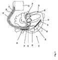
- FIG. 1a three chamber pacemaker/implantable defibrillator/cardioverter ICD 10 as heart stimulator connected to pacing/sensing leads placed in a heart 12 is illustrated.
- ICD 10is electrically coupled to heart 12 by way of leads 14 , 16 and 30 .
- Lead 14has a pair of right atrial electrodes 18 and 20 that are in contact with the right atria 26 of the heart 12 .
- Lead 16has a pair of electrodes 22 and 24 that are in contact with the right ventricle 28 of heart 12 .
- Lead 16also has a ventricular defibrillation electrode 36 and an vena cava defibrillation electrode 38 .
- Electrodes 18 and 22are tip-electrodes at the very distal end of leads 14 and 16 , respectively. Electrode 18 is a right atrial tip electrode RA-Tip and electrode 22 is a right ventricular tip electrode 22 . Electrodes 20 and 24 are ring electrodes in close proximity but electrically isolated from the respective tip electrodes 18 and 22 . Electrode 20 forms a right atrial ring electrode RA-Ring and electrode 24 forms a right ventricular ring electrode RV-Ring. Defibrillation electrodes 36 and 38 are helical coil electrodes providing a large surface.
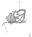
- Electrode lead 30is a coronary sinus electrode lead that provides a left ventricular tip electrode 32 at its very distal end. Furthermore, where electrode lead 30 circumvents mitral valve 40 of heart 12 , a Doppler sensor 34 is integrated into electrode lead 30 .
- Doppler sensor 34comprises a piezoelectric crystal for emitting directed ultrasonic waves and an ultrasound receiver. Such Doppler sensor is generally known in the art.
- FIG. 2a simplified block diagram of a three chamber pacemaker 10 ′ is illustrated. No defibrillator is illustrated. However, pacemaker 10 ′ could provide added modules for delivery of defibrillation shocks via electrodes 36 and 38 as shown in FIG. 1 .
- pacemaker leads 14 , 16 and 30are connected to respective output/input terminals of pacemaker 10 as indicated in FIG. 1 and carry stimulating pulses to the tip electrodes 18 , 22 and 32 from an atrial stimulation pulse generator A-STIM 42 , a right ventricular pulse generator RV-STIM 44 and a left ventricular pulse generator LV-STIM 60 , respectively.
- electrical signals from the atriumare carried from the electrode pair 18 and 20 , through the lead 14 , to the input terminal of an atrial channel sensing stage A-SENS 46 ; and electrical signals from the right ventricle are carried from the electrode pair 22 and 24 , through the lead 16 , to the input terminal of a right ventricular sensing stage RV-SENS 48 .
- Doppler sensor 34is connected to a Doppler sensor control unit 64 via electrode lead 30 as well.
- Controlling the dual chamber pacer 10is a control unit CTRL 50 that is connected to sensing stages A-SENS 46 , RV-SENS 48 and LV-SENS 62 and to stimulation pulse generators A-STIM 42 , RV-STIM 44 and LV-STIM 60 .
- Control unit CTRL 50receives the output signals from the atrial sensing stage A-SENS 46 and from the ventricular sensing stages RV-SENS 48 and LV-SENS 62 .
- the output signals of sensing stages A-SENS 46 and RV-SENS 48are generated each time that a P-wave representing an intrinsic atrial event or an R-wave representing an intrinsic right ventricular event, respectively, is sensed within the heart 12 .
- An As-signalis generated, when the atrial sensing stage A-SENS 46 detects a P-wave and a Vs-signal is generated, when the right ventricular sensing stage V-SENS 48 detects an R-wave.
- Control unit CTRL 50also generates trigger signals that are sent to the atrial stimulation pulse generator A-STIM 42 and the ventricular stimulation pulse generators RV-STIM 44 and LV-STIM 60 , respectively. These trigger signals are generated each time that a stimulation pulse is to be generated by the respective pulse generators A-STIM 42 , RV-STIM 44 or LV-STIM 60 .
- the atrial trigger signalis referred to simply as the “A-pulse”
- the ventricular trigger signalsare referred to as the “RV-pulse” or “LV-pulse”, respectively.
- the corresponding sensing stage, A-SENS 46 and/or RV-SENS 48 and/or LV-SENS 60is typically disabled by way of a blanking signal presented to these amplifiers from the control unit CTRL 50 , respectively.
- This blanking actionprevents the sensing stages A-SENS 46 , RV-SENS 48 and LV-SENS 62 from becoming saturated from the relatively large stimulation pulses that are present at their input terminals during this time.
- This blanking actionalso helps prevent residual electrical signals present in the muscle tissue as a result of the pacer stimulation from being interpreted as P-waves or R-waves.
- Atrial sense eventsAs recorded shortly after delivery of a ventricular stimulation pulses during a preset time interval called post ventricular atrial refractory period (PVARP) are generally recorded as atrial refractory sense event A rs but ignored.
- PVARPpost ventricular atrial refractory period
- Control unit CTRL 50comprises circuitry for timing ventricular and/or atrial stimulation pulses according to an adequate stimulation rate that can be adapted to a patient's hemodynamic need.
- the pacer 10may also include a memory circuit MEM 52 that is coupled to the control unit CTRL 50 over a suitable data/address bus ADR 54 .
- This memory circuit MEM 52allows certain control parameters, used by the control unit CTRL 50 in controlling the operation of the pacemaker 10 , to be programmably stored and modified, as required, in order to customize the pacemaker's operation to suit the needs of a particular patient.
- dataincludes the basic timing intervals used during operation of the pacemaker.
- data sensed during the operation of the pacermay be stored in the memory MEM 52 for later retrieval and analysis.
- a telemetry circuit TEL 56is further included in the pacemaker 10 .
- This telemetry circuit TEL 56is connected to the control unit CTRL 50 by way of a suitable command/data bus. Telemetry circuit TEL 56 allows for wireless data exchange between the pacemaker 10 and some remote programming or analyzing device which can be part of a centralized service center serving multiple pacemakers.
- the pacemaker 10 in FIG. 1is referred to as a three chamber pacemaker because it interfaces with the right atrium 26 , the right ventricle 28 and the left ventricle of the heart 12 .
- Those portions of the pacemaker 10 that interface with the right atrium, e.g., the lead 14 , the P-wave sensing stage A-SENS 46 , the atrial stimulation pulse generator A-STIM 42 and corresponding portions of the control unit CTRL 50are commonly referred to as the atrial channel RA.
- a left ventricular channelincludes those portions of the pacemaker 10 that interface with the left ventricle, e.g., the lead 30 , the left ventricular sensing stage LV-SENS 62 , the left ventricular stimulation pulse generator LV-STIM 60 , and corresponding portions LV of the control unit CTRL 50
- the pacemaker 10further includes a physiological sensor ACT 58 that is connected to the control unit CTRL 50 of the pacemaker 10 . While this sensor ACT 58 is illustrated in FIG. 2 as being included within the pacemaker 10 , it is to be understood that the sensor may also be external to the pacemaker 10 , yet still be implanted within or carried by the patient.
- a common type of sensoris an activity sensor, such as a piezoelectric crystal, mounted to the case of the pacemaker.
- Other types of physiologic sensorsare also known, such as sensors that sense the oxygen content of blood, respiration rate, pH of blood, body motion, and the like. The type of sensor used is not critical to the present invention. Any sensor capable of sensing some physiological parameter relatable to the rate at which the heart should be beating can be used. Such sensors are commonly used with “rate-responsive” pacemakers in order to adjust the rate of the pacemaker in a manner that tracks the physiological needs of the patient.
- Doppler sensor 34is integrated into coronary sinus electrode lead 30 .
- Arrangement of Doppler sensor 34is such that its ultrasonic transducer is placed on electrode lead 30 at a position in the coronary sinus that is close to the mitral valve 40 , when the electrode lead is in its implanted state; see FIG. 3 .
- the ultrasonic transduceris adapted in a way that an emitted acoustic wave 66 travels into a direction perpendicular to the electrode lead 30 and the reflected signal is received from that direction, respectively.
- the piezoelectric crystal of the ultrasonic transducerhas lateral dimensions that are adapted to the wavelength of an emitted ultrasonic wave 66 such that the emitted ultrasonic wave has an angle of beam spread of about 10° to 60°.
- Doppler sensor 34 ′can be integrated into coronary sinus electrode lead 30 ′ such that its ultrasonic transducer is placed a position in the great cardiac vein, when the electrode lead is in its implanted state; see FIG. 4 .
- the ultrasonic transducerthen is adapted in a way that an emitted acoustic wave 66 travels into a proximal direction with respect to the electrode lead 30 ′ and the reflected acoustic wave signal is received from that direction, respectively.
- the piezoelectric crystal of the ultrasonic transducer of Doppler sensor 34 ′has lateral dimensions that are adapted to the wavelength of an emitted ultrasonic wave 66 ′ such that the emitted ultrasonic wave has an angle of beam spread of about 10° to 60°.
- Doppler sensor 34 ′can be part of atrial electrode lead 14 such that Doppler sensor 34 ′′ is placed in the right atrium close to the atrial septum; see FIG. 5 .
- the piezoelectric crystal of Doppler sensor 34 ′′is dimensioned such that the emitted ultrasonic wave 66 ′′ has an angle of beam spread of about 10° to 60°.
- Doppler sensor 34 ′′is part of right ventricular electrode lead 16 such that Doppler sensor 34 ′′′ is placed in the right ventricle as shown in FIG. 6 .
- Dimensions of the piezoelectric crystal of Doppler sensor 34 ′′′are such that the emitted ultrasonic wave 66 ′′′ has an angle of beam spread of about 10° to 60°.
- the acoustic transmitter and receiver of the ultrasonic transduceris implemented by a single sensor crystal positioned on the lead.
- the crystalis a piezoelectric crystal that is excited by a voltage pulse of high frequency electrical energy within a frequency range of 2 MHz-5 MHz. This electrical energy of the high frequency pulse is converted by the crystal into ultrasonic acoustic wave that is emitted and sonifies the blood and shifts the frequency when reflected by the blood.
- the reflected acoustic wave signalis received by the crystal and transformed in a high frequency electric signal that can be further processed in order to receive a flow velocity signal.
- the flow velocity signalpreferably is derived from a frequency shift between the emitted acoustic wave and the reflected signal that is picked up by the same crystal.
- the piezoelectric crystal together with Doppler sensor control unit 64form a Doppler sensor, that is connected to control unit CTRL 50 and that forwards a flow velocity signal to control unit 50 when activated.
- the piezoelectric crystalpreferably is made from Barium Titanate and is connected to Doppler sensor control unit 64 by way of a coax cable in electrode lead 30 .
- the ultrasonic transducer control unit 64is adapted to excite the crystal by a high frequency voltage pulse of a frequency of about 5 MHz.
- the high frequency voltage pulsehas a voltage in the order of 10 volts and a pulse duration in the order of 1 to 5 micro-seconds. The pulse duration is shorter than an expected time of flight between emission of said acoustic wave and receiving said reflected signal.
- the ultrasonic transducer control unit 64is adapted to amplify and mix the electric signal generated by the crystal when receiving the reflected ultrasonic acoustic wave signal to eliminate a carrier frequency and to generate a Doppler shift signal reflecting a flow velocity.
- the Doppler shift signalis the flow velocity signal that is forwarded to control unit CTRL 50 for further processing.
- the Doppler sensor formed by the piezoelectric crystal and the ultrasonic transducer control unit 64is not permanently activated.
- ultrasonic transducer control unit 64For one flow velocity measurement, ultrasonic transducer control unit 64 generates high frequency pulses with a duty cycle of 5 pulses in a time window of 100 ms to 300 ms duration beginning with a left atrial excitation or contraction, that is, a left atrial event. Flow velocity measurement is carried out during a measurement period of 5 to 10 minutes a day.
- the control unit CTRL 50is adapted to determine an adequate heart rate or stimulation rate in any manner known as such.
- the control unit CTRL 50uses the flow velocity signal received from the Doppler sensor in different ways:
- the optimal time for the LV stimulation pulseis when the ventricular filling phase is completed.
- the IMD 10measures the mitral flow after a LA event (sense or pace) and paces the LV when the flow comes to zero, close to zero, or below a certain threshold value. This enables not only baseline AVD optimization at rest but also optimization under all conditions during daily life. For this dynamic AVD optimization the AVD is varied for a few beats each and the optimal value determined from the flow sensor signal. The so found value is stored in memory MEM 52 of IMD 10 together with the heart rate under which the value was determined. This procedure is repeated under different metabolic conditions, i.e., for different heart rates. The heart rate may be intrinsic or sensor driven.
- a table in memory MEM 52is created that allocates an optimal AVD value to each heart rate. Separate tables exist for different event types, e.g., for atrial paced and sensed events.
- Control unit CTRL 50 of IMD 10triggers ventricular stimulation pulses with an optimal AVD in dependence of the current heart rate due to the table. The whole procedure may be repeated from time to time to track changed physiologic conditions.
- the AV-delaycan be optimized based on an evaluation of the mitral stroke volume such that the mitral velocity-time integral VTI is maximized.
- MRe.g. can be caused by a valve insufficiency or by poor synchronization of the ventricles (see below).
- the amount of mitral backflow during the systoleis determined by control unit CTRL 50 and stored/transmitted as a diagnostic parameter.
- a MR severity indexcan be estimated.
- the amount of reversely streaming bloodis estimated from the temporal velocity distribution of backflow from the left ventricle into the left atrium, e.g., by the velocity-time-integral VTI of the mitral reflux.
- the MRalso can be determined from the difference of the mitral SV (estimated from the mitral velocity-time integral VTI) and the aortic SV (estimated from the aortic VTI).
- IMD 10optimizes a cardiac resynchronization therapy CRT wherein both ventricles are paced by means of right ventricular stimulation pulse generator 44 and left ventricular stimulation pulse generator 60 such that MR is minimized.
- the pacing mode (RV stimulation, LV stimulation or BiV stimulation) and the interventricular delay VVD in case of biventricular stimulationare automatically adjusted by control unit CTRL 50 based on the MR measurements by means of the Doppler sensor 34 .
- Control unitswitches between different modes of pacing from time to time in order to determine a pacing mode resulting in a minimum MR.
- the pacing modeis biventricular stimulation mode wherein both ventricles are pace with a programmable interventricular delay VVD
- the VVDis automatically varied till a value with a minimal MR is found. This value is considered to be the best one as the optimal synchronization and the best pumping efficacy of the LV is obtained.
- the systolic left ventricular pressure gradientcan be assessed from the MR measurements, i.e., from the velocity of blood that streams back into the left atrium during the pre ejection period PEP.
- the left atrial pressure gradientcan be estimated from the Bernoulli equation:
- the left ventricular pressure gradientis computed by control unit CTRL 50 from two consecutive left atrial velocity measurements during the PEP.
- the max. dp/dtfor instance can be estimated, if several measurements are taken within the PEP.
- dp/dt_maxis a measure for the left ventricular contractility. The relevance of this parameter for several diagnostic and therapeutic options is described elsewhere and needs not to be discussed here.
- the advantage of this methodis, that the left ventricular pressure gradient can be continuously monitored from an implanted electrode lead without the need for a pressure sensor. This method may be combined with other methods, e.g., with the determination of left ventricular volume changes via the intracardiac impedance measurement, which is described elsewhere.
- the relaxation function of the LVcan be assessed.
- the mitral flow during the relaxation phaseis used as an additional diagnostic marker to characterize the function of the left ventricular myocardium.
- One marker of impaired left ventricular diastolic functionis a prolonged isovolumetric relaxation time, i.e., an increased period between aortic valve closure and mitral valve opening. Under rest conditions this time can be estimated by the period between the ventricular (paced or sensed) event and the beginning of mitral flow into the left ventricle.
- Another marker for diastolic malfunctionis a decreased mitral flow velocity during passive filling of the left ventricle, i.e., before the atrial contraction.
- the accuracy of the outlined methods based on mitral blood flowmay be increased by a calibration with an external echo system. E.g., errors by a non-optimal angle of the sensor and the sound wave direction in relation to the blood stream may be compensated. Therefore, the Doppler sensor for measuring mitral blood flow is calibrated by means of an external echocardiography from time to time.
- the data obtained from the sensoris condensed in IMD 10 , e.g., by averaging or by data compression, and is transmitted by telemetry unit TEL 56 to a service center.
- Data transmissionis performed in a way that is generally known from the Home Monitoring concept, e.g., by transmission from the IMD to a bedside unit and broadcasting from this device to a central service center which includes a database.
- the service centerthe data is collected and stored on a long-term basis, evaluated, and presented to the physician.
- the sensor datamay be input into expert systems for automatic evaluation, alarm generation on certain conditions, risk assessment etc.
- the data from the described acoustic sensormay be evaluated in combination with other sensor signals in the service center and information from the implant to increase the reliability of a diagnosis.
Landscapes
- Health & Medical Sciences (AREA)
- Life Sciences & Earth Sciences (AREA)
- Heart & Thoracic Surgery (AREA)
- Radiology & Medical Imaging (AREA)
- General Health & Medical Sciences (AREA)
- Veterinary Medicine (AREA)
- Public Health (AREA)
- Engineering & Computer Science (AREA)
- Biomedical Technology (AREA)
- Nuclear Medicine, Radiotherapy & Molecular Imaging (AREA)
- Cardiology (AREA)
- Animal Behavior & Ethology (AREA)
- Biophysics (AREA)
- Hematology (AREA)
- Physics & Mathematics (AREA)
- Pathology (AREA)
- Medical Informatics (AREA)
- Molecular Biology (AREA)
- Surgery (AREA)
- Physiology (AREA)
- Electrotherapy Devices (AREA)
Abstract
Description
- the ultrasonic transducer control unit is adapted to excite the ultrasonic transducer by a pulse of electrical energy within a frequency range of 2 MHz-8 MHz, preferably below 5 MHz.
- the ultrasonic transducer control unit is adapted to excite the ultrasonic transducer with a high frequency voltage pulse having a sufficient voltage in the order of e.g. 10 volts (in the case the ultrasonic transducer is a piezoelectric crystal), wherein the high frequency voltage pulse preferably has a pulse duration in the order of 1 to 5 micro-seconds. The pulse duration preferably is shorter than an expected time of flight between emission of said acoustic wave and receiving said reflected signal. Thus, all energy of the high frequency voltage pulse is ‘quenched’ prior to looking at the reflected signal.
- the ultrasonic transducer control unit is adapted to amplify and mix a received signal generated by the ultrasonic transducer when receiving a reflected signal to eliminate a carrier frequency and to generate a Doppler shift signal reflecting a flow velocity. This is, because the electric signal generated by the ultrasonic transducer—in particular if the ultrasonic transducer is a piezoelectric crystal—from the reflected acoustic wave signal is usually in the order of micro volts which then has to be appropriately amplified and mixed to eliminate the carrier and look for the Doppler shift. The signal processing is similar to a radio receiver.
- the ultrasonic transducer control unit is adapted to generate high frequency pulses with a duty cycle of 3 to 9 pulses in with a time window of 100 ms to 300 ms duration beginning with a left atrial excitation or contraction, that is, a left atrial event. The flow through the mitral valve is comparatively slow which means the Doppler shift will be small and smeared over the time of the AV delay, usually about 160 ms. As little as 5 pulses are believed to give a good indication of the flow through the mitral valve.
- the ultrasonic transducer control unit is adapted to apply a time window for receiving a reflected signal wherein the time window is adapted to an expected time of flight between emission of said acoustic wave (ultrasonic pulse) and receiving said reflected signal in order evaluate only that part of the reflected signal that is reflected by a region of interest, e.g. blood flow through the mitral valve. Thus, interference by other reflected signals reflected from other blood flows e.g. in the coronary artery, can be eliminated. Preferably, the time window for receiving the reflected signal after emitting an ultrasonic pulse is adjustable in order to allow adaptation to a particular position of the ultrasonic transducer after implantation of the electrode lead carrying the transducer.
- the ultrasonic transducer control unit is adapted to generate high frequency pulses only within a measurement period of 5 to 10 minutes a day. This further saves energy.
- with pLV—LV blood pressure
- νLA—LA blood velocity
- ρblood—blood density.
Claims (19)
Applications Claiming Priority (3)
| Application Number | Priority Date | Filing Date | Title |
|---|---|---|---|
| EPEP06025401.8 | 2006-12-08 | ||
| EP06025401AEP1930045A1 (en) | 2006-12-08 | 2006-12-08 | Implantable medical system with acoustic sensor to measure mitral blood flow |
| EP06025401 | 2006-12-08 |
Publications (2)
| Publication Number | Publication Date |
|---|---|
| US20080146934A1 US20080146934A1 (en) | 2008-06-19 |
| US8521282B2true US8521282B2 (en) | 2013-08-27 |
Family
ID=37781674
Family Applications (1)
| Application Number | Title | Priority Date | Filing Date |
|---|---|---|---|
| US11/948,935Expired - Fee RelatedUS8521282B2 (en) | 2006-12-08 | 2007-11-30 | Implantable medical system with acoustic sensor to measure mitral blood flow |
Country Status (2)
| Country | Link |
|---|---|
| US (1) | US8521282B2 (en) |
| EP (1) | EP1930045A1 (en) |
Cited By (9)
| Publication number | Priority date | Publication date | Assignee | Title |
|---|---|---|---|---|
| US10806352B2 (en) | 2016-11-29 | 2020-10-20 | Foundry Innovation & Research 1, Ltd. | Wireless vascular monitoring implants |
| US10806428B2 (en) | 2015-02-12 | 2020-10-20 | Foundry Innovation & Research 1, Ltd. | Implantable devices and related methods for heart failure monitoring |
| US11039813B2 (en) | 2015-08-03 | 2021-06-22 | Foundry Innovation & Research 1, Ltd. | Devices and methods for measurement of Vena Cava dimensions, pressure and oxygen saturation |
| US11206992B2 (en) | 2016-08-11 | 2021-12-28 | Foundry Innovation & Research 1, Ltd. | Wireless resonant circuit and variable inductance vascular monitoring implants and anchoring structures therefore |
| US11452497B2 (en)* | 2020-05-19 | 2022-09-27 | Coravie Medical, Inc. | Injectable hemodynamic monitoring devices, systems and methods |
| US11564596B2 (en) | 2016-08-11 | 2023-01-31 | Foundry Innovation & Research 1, Ltd. | Systems and methods for patient fluid management |
| US11701018B2 (en) | 2016-08-11 | 2023-07-18 | Foundry Innovation & Research 1, Ltd. | Wireless resonant circuit and variable inductance vascular monitoring implants and anchoring structures therefore |
| US11779238B2 (en) | 2017-05-31 | 2023-10-10 | Foundry Innovation & Research 1, Ltd. | Implantable sensors for vascular monitoring |
| US11944495B2 (en) | 2017-05-31 | 2024-04-02 | Foundry Innovation & Research 1, Ltd. | Implantable ultrasonic vascular sensor |
Families Citing this family (44)
| Publication number | Priority date | Publication date | Assignee | Title |
|---|---|---|---|---|
| US7520860B2 (en)* | 2005-04-13 | 2009-04-21 | Marie G. Johnson | Detection of coronary artery disease using an electronic stethoscope |
| DE102007054178A1 (en)* | 2007-11-14 | 2009-05-20 | Biotronik Crm Patent Ag | Biventricular cardiac stimulator |
| US11254926B2 (en) | 2008-04-29 | 2022-02-22 | Virginia Tech Intellectual Properties, Inc. | Devices and methods for high frequency electroporation |
| US11272979B2 (en) | 2008-04-29 | 2022-03-15 | Virginia Tech Intellectual Properties, Inc. | System and method for estimating tissue heating of a target ablation zone for electrical-energy based therapies |
| US10702326B2 (en) | 2011-07-15 | 2020-07-07 | Virginia Tech Intellectual Properties, Inc. | Device and method for electroporation based treatment of stenosis of a tubular body part |
| US10272178B2 (en) | 2008-04-29 | 2019-04-30 | Virginia Tech Intellectual Properties Inc. | Methods for blood-brain barrier disruption using electrical energy |
| US10117707B2 (en) | 2008-04-29 | 2018-11-06 | Virginia Tech Intellectual Properties, Inc. | System and method for estimating tissue heating of a target ablation zone for electrical-energy based therapies |
| US10245098B2 (en) | 2008-04-29 | 2019-04-02 | Virginia Tech Intellectual Properties, Inc. | Acute blood-brain barrier disruption using electrical energy based therapy |
| US9867652B2 (en) | 2008-04-29 | 2018-01-16 | Virginia Tech Intellectual Properties, Inc. | Irreversible electroporation using tissue vasculature to treat aberrant cell masses or create tissue scaffolds |
| US9283051B2 (en) | 2008-04-29 | 2016-03-15 | Virginia Tech Intellectual Properties, Inc. | System and method for estimating a treatment volume for administering electrical-energy based therapies |
| US9198733B2 (en) | 2008-04-29 | 2015-12-01 | Virginia Tech Intellectual Properties, Inc. | Treatment planning for electroporation-based therapies |
| US9598691B2 (en) | 2008-04-29 | 2017-03-21 | Virginia Tech Intellectual Properties, Inc. | Irreversible electroporation to create tissue scaffolds |
| US8992517B2 (en) | 2008-04-29 | 2015-03-31 | Virginia Tech Intellectual Properties Inc. | Irreversible electroporation to treat aberrant cell masses |
| US10238447B2 (en) | 2008-04-29 | 2019-03-26 | Virginia Tech Intellectual Properties, Inc. | System and method for ablating a tissue site by electroporation with real-time monitoring of treatment progress |
| FR2935604B1 (en)* | 2008-09-08 | 2012-01-06 | Centre Nat Rech Scient | METHOD AND DEVICE FOR MARKING A MEDIUM, AND MARKER USABLE IN SUCH A METHOD |
| US8632534B2 (en) | 2009-04-03 | 2014-01-21 | Angiodynamics, Inc. | Irreversible electroporation (IRE) for congestive obstructive pulmonary disease (COPD) |
| US11382681B2 (en) | 2009-04-09 | 2022-07-12 | Virginia Tech Intellectual Properties, Inc. | Device and methods for delivery of high frequency electrical pulses for non-thermal ablation |
| US11638603B2 (en) | 2009-04-09 | 2023-05-02 | Virginia Tech Intellectual Properties, Inc. | Selective modulation of intracellular effects of cells using pulsed electric fields |
| WO2010138919A2 (en)* | 2009-05-28 | 2010-12-02 | Angiodynamics, Inc. | System and method for synchronizing energy delivery to the cardiac rhythm |
| US9895189B2 (en) | 2009-06-19 | 2018-02-20 | Angiodynamics, Inc. | Methods of sterilization and treating infection using irreversible electroporation |
| US20110054333A1 (en)* | 2009-08-28 | 2011-03-03 | Stentronics, Inc. | Stent Flow Sensor |
| US20110137210A1 (en)* | 2009-12-08 | 2011-06-09 | Johnson Marie A | Systems and methods for detecting cardiovascular disease |
| EP2627274B1 (en) | 2010-10-13 | 2022-12-14 | AngioDynamics, Inc. | System for electrically ablating tissue of a patient |
| WO2012088149A2 (en) | 2010-12-20 | 2012-06-28 | Virginia Tech Intellectual Properties, Inc. | High-frequency electroporation for cancer therapy |
| US20120197141A1 (en)* | 2011-01-28 | 2012-08-02 | Pacesetter, Inc. | Implantable echo doppler flow sensor for monitoring of hemodynamics |
| US20140288611A1 (en)* | 2011-09-02 | 2014-09-25 | Adelina Pancheva | Zero blood flow sensitive heart stimulator |
| US9078665B2 (en) | 2011-09-28 | 2015-07-14 | Angiodynamics, Inc. | Multiple treatment zone ablation probe |
| US9414881B2 (en) | 2012-02-08 | 2016-08-16 | Angiodynamics, Inc. | System and method for increasing a target zone for electrical ablation |
| US9801721B2 (en)* | 2012-10-12 | 2017-10-31 | St. Jude Medical, Cardiology Division, Inc. | Sizing device and method of positioning a prosthetic heart valve |
| US9888956B2 (en) | 2013-01-22 | 2018-02-13 | Angiodynamics, Inc. | Integrated pump and generator device and method of use |
| US10716482B2 (en) | 2013-04-25 | 2020-07-21 | Hexacath | Thermodilution catheter systems and methods for determining blood flow rates |
| US11813416B2 (en) | 2013-04-25 | 2023-11-14 | Hexacath | Catheter systems and methods for performing a destruction of a body obstruction |
| WO2015175570A1 (en) | 2014-05-12 | 2015-11-19 | Virginia Tech Intellectual Properties, Inc. | Selective modulation of intracellular effects of cells using pulsed electric fields |
| US12114911B2 (en) | 2014-08-28 | 2024-10-15 | Angiodynamics, Inc. | System and method for ablating a tissue site by electroporation with real-time pulse monitoring |
| US10694972B2 (en) | 2014-12-15 | 2020-06-30 | Virginia Tech Intellectual Properties, Inc. | Devices, systems, and methods for real-time monitoring of electrophysical effects during tissue treatment |
| CN112043259B (en)* | 2015-07-10 | 2025-01-10 | 深圳迈瑞生物医疗电子股份有限公司 | Monitoring system, method and device |
| FR3052075B1 (en) | 2016-06-01 | 2022-01-07 | Hexacath | INFUSION CATHETER DEVICE FOR TREATING AT LEAST PARTIAL OR COMPLETE OBSTRUCTION IN A DUCT, SUCH AS BODY DUCT |
| US10905492B2 (en) | 2016-11-17 | 2021-02-02 | Angiodynamics, Inc. | Techniques for irreversible electroporation using a single-pole tine-style internal device communicating with an external surface electrode |
| US11607537B2 (en) | 2017-12-05 | 2023-03-21 | Virginia Tech Intellectual Properties, Inc. | Method for treating neurological disorders, including tumors, with electroporation |
| US11311329B2 (en) | 2018-03-13 | 2022-04-26 | Virginia Tech Intellectual Properties, Inc. | Treatment planning for immunotherapy based treatments using non-thermal ablation techniques |
| US12390262B2 (en) | 2018-03-13 | 2025-08-19 | Virginia Tech Intellectual Properties, Inc. | Treatment planning system for immunotherapy enhancement via non-thermal ablation |
| US11925405B2 (en) | 2018-03-13 | 2024-03-12 | Virginia Tech Intellectual Properties, Inc. | Treatment planning system for immunotherapy enhancement via non-thermal ablation |
| US11950835B2 (en) | 2019-06-28 | 2024-04-09 | Virginia Tech Intellectual Properties, Inc. | Cycled pulsing to mitigate thermal damage for multi-electrode irreversible electroporation therapy |
| US12214189B2 (en) | 2019-07-24 | 2025-02-04 | Virginia Tech Intellectual Properties, Inc. | Fourier analysis spectroscopy for monitoring tissue impedance changes and treatment outcome during electroporation-based-therapies |
Citations (28)
| Publication number | Priority date | Publication date | Assignee | Title |
|---|---|---|---|---|
| US5139020A (en) | 1991-03-08 | 1992-08-18 | Telectronics Pacing Systems, Inc. | Method and apparatus for controlling the hemodynamic state of a patient based on systolic time interval measurements detecting using doppler ultrasound techniques |
| US5156154A (en) | 1991-03-08 | 1992-10-20 | Telectronics Pacing Systems, Inc. | Monitoring the hemodynamic state of a patient from measurements of myocardial contractility using doppler ultrasound techniques |
| US5156157A (en) | 1991-03-08 | 1992-10-20 | Telectronics Pacing Systems, Inc. | Catheter-mounted doppler ultrasound transducer and signal processor |
| US5183040A (en) | 1991-03-08 | 1993-02-02 | Telectronics Pacing Systems, Inc. | Apparatus and method for detecting abnormal cardiac rhythms using an ultrasound sensor in an arrhythmia control system |
| US5188106A (en) | 1991-03-08 | 1993-02-23 | Telectronics Pacing Systems, Inc. | Method and apparatus for chronically monitoring the hemodynamic state of a patient using doppler ultrasound |
| US5243976A (en) | 1990-09-11 | 1993-09-14 | Ferek Petric Bozidar | Tricuspid flow synchronized cardiac electrotherapy system with blood flow measurement transducer and controlled pacing signals based on blood flow measurement |
| US5325860A (en)* | 1991-11-08 | 1994-07-05 | Mayo Foundation For Medical Education And Research | Ultrasonic and interventional catheter and method |
| US5334222A (en) | 1992-11-03 | 1994-08-02 | Cardiac Pacemakers, Inc. | Cardiac stimulating apparatus and method for heart failure therapy |
| US5409009A (en) | 1994-03-18 | 1995-04-25 | Medtronic, Inc. | Methods for measurement of arterial blood flow |
| US5535751A (en)* | 1994-12-22 | 1996-07-16 | Morphometrix Technologies Inc. | Confocal ultrasonic imaging system |
| US5544656A (en) | 1994-12-02 | 1996-08-13 | The Regents Of The University Of California | Method and apparatus for myocardial wall measurement |
| US5795298A (en)* | 1995-03-28 | 1998-08-18 | Sonometrics Corporation | System for sharing electrocardiogram electrodes and transducers |
| US5876345A (en)* | 1997-02-27 | 1999-03-02 | Acuson Corporation | Ultrasonic catheter, system and method for two dimensional imaging or three-dimensional reconstruction |
| US6298269B1 (en) | 1999-04-19 | 2001-10-02 | Cardiac Pacemakers, Inc. | Cardiac rhythm management system with ultrasound for autocapture or other applications |
| US6398734B1 (en) | 1997-10-14 | 2002-06-04 | Vascusense, Inc. | Ultrasonic sensors for monitoring the condition of flow through a cardiac valve |
| US6421565B1 (en) | 1997-08-06 | 2002-07-16 | Pacesetter Ab | Cardiac monitoring device and a rate responsive pacemaker system |
| US20030023296A1 (en) | 2001-07-25 | 2003-01-30 | Osypka Thomas P. | Implantable coronary sinus lead with mapping capabilities |
| US20030083702A1 (en) | 2001-10-30 | 2003-05-01 | Stadler Robert W. | Implantable medical device employing sonomicrometer output signals for detection and measurement of cardiac mechanical function |
| US20030195496A1 (en)* | 2000-05-16 | 2003-10-16 | Maguire Mark A. | Apparatus and method incorporating an ultrasound transducer onto a delivery member |
| US20030199936A1 (en)* | 2002-04-22 | 2003-10-23 | Struble Chester L. | Atrioventricular delay adjustment |
| US20030204140A1 (en)* | 2002-04-25 | 2003-10-30 | Bozidar Ferek-Patric | Ultrasound methods and implantable medical devices using same |
| EP1410756A1 (en) | 2002-10-18 | 2004-04-21 | Pacesetter, Inc. | Hemodynamic analysis, in particular in a pacemaker |
| US6740076B2 (en) | 2002-04-26 | 2004-05-25 | Medtronic, Inc. | Ultrasonic septum monitoring for implantable medical devices |
| US20040176688A1 (en)* | 2002-04-05 | 2004-09-09 | Cardiac Pacemakers, Inc. | Doppler guiding catheter using sensed blood turbulence levels |
| US20050027323A1 (en) | 2001-10-30 | 2005-02-03 | Medtronic, Inc. | Implantable medical device for monitoring cardiac blood pressure and chamber dimension |
| US6970742B2 (en) | 2000-01-11 | 2005-11-29 | Savacor, Inc. | Method for detecting, diagnosing, and treating cardiovascular disease |
| US20060100668A1 (en) | 2001-08-31 | 2006-05-11 | Biocontrol Medical Ltd. | Selective nerve fiber stimulation |
| US20100125210A1 (en)* | 2003-11-26 | 2010-05-20 | Hastings Harold M | Ultrasound transducer for transesophageal imaging |
- 2006
- 2006-12-08EPEP06025401Apatent/EP1930045A1/ennot_activeWithdrawn
- 2007
- 2007-11-30USUS11/948,935patent/US8521282B2/ennot_activeExpired - Fee Related
Patent Citations (34)
| Publication number | Priority date | Publication date | Assignee | Title |
|---|---|---|---|---|
| US5243976A (en) | 1990-09-11 | 1993-09-14 | Ferek Petric Bozidar | Tricuspid flow synchronized cardiac electrotherapy system with blood flow measurement transducer and controlled pacing signals based on blood flow measurement |
| US5316001A (en) | 1990-09-11 | 1994-05-31 | Ferek Petric Bozidar | Cardiac measurement system for measuring blood flow velocity by use of a sensor implanted inside the heart |
| US5139020A (en) | 1991-03-08 | 1992-08-18 | Telectronics Pacing Systems, Inc. | Method and apparatus for controlling the hemodynamic state of a patient based on systolic time interval measurements detecting using doppler ultrasound techniques |
| US5156154A (en) | 1991-03-08 | 1992-10-20 | Telectronics Pacing Systems, Inc. | Monitoring the hemodynamic state of a patient from measurements of myocardial contractility using doppler ultrasound techniques |
| US5156157A (en) | 1991-03-08 | 1992-10-20 | Telectronics Pacing Systems, Inc. | Catheter-mounted doppler ultrasound transducer and signal processor |
| US5183040A (en) | 1991-03-08 | 1993-02-02 | Telectronics Pacing Systems, Inc. | Apparatus and method for detecting abnormal cardiac rhythms using an ultrasound sensor in an arrhythmia control system |
| US5188106A (en) | 1991-03-08 | 1993-02-23 | Telectronics Pacing Systems, Inc. | Method and apparatus for chronically monitoring the hemodynamic state of a patient using doppler ultrasound |
| US5325860A (en)* | 1991-11-08 | 1994-07-05 | Mayo Foundation For Medical Education And Research | Ultrasonic and interventional catheter and method |
| US5334222A (en) | 1992-11-03 | 1994-08-02 | Cardiac Pacemakers, Inc. | Cardiac stimulating apparatus and method for heart failure therapy |
| US5584868A (en)* | 1992-11-03 | 1996-12-17 | Cardiac Pacemakers, Inc. | Cardiac stimulating apparatus and method for heart failure therapy |
| US5409009A (en) | 1994-03-18 | 1995-04-25 | Medtronic, Inc. | Methods for measurement of arterial blood flow |
| US5544656A (en) | 1994-12-02 | 1996-08-13 | The Regents Of The University Of California | Method and apparatus for myocardial wall measurement |
| US5535751A (en)* | 1994-12-22 | 1996-07-16 | Morphometrix Technologies Inc. | Confocal ultrasonic imaging system |
| US5795298A (en)* | 1995-03-28 | 1998-08-18 | Sonometrics Corporation | System for sharing electrocardiogram electrodes and transducers |
| US5876345A (en)* | 1997-02-27 | 1999-03-02 | Acuson Corporation | Ultrasonic catheter, system and method for two dimensional imaging or three-dimensional reconstruction |
| US6421565B1 (en) | 1997-08-06 | 2002-07-16 | Pacesetter Ab | Cardiac monitoring device and a rate responsive pacemaker system |
| US6398734B1 (en) | 1997-10-14 | 2002-06-04 | Vascusense, Inc. | Ultrasonic sensors for monitoring the condition of flow through a cardiac valve |
| US6757563B2 (en) | 1999-04-19 | 2004-06-29 | Cardiac Pacemakers, Inc. | Cardiac rhythm management system with ultrasound for autocapture or other applications |
| US6298269B1 (en) | 1999-04-19 | 2001-10-02 | Cardiac Pacemakers, Inc. | Cardiac rhythm management system with ultrasound for autocapture or other applications |
| US6970742B2 (en) | 2000-01-11 | 2005-11-29 | Savacor, Inc. | Method for detecting, diagnosing, and treating cardiovascular disease |
| US20030195496A1 (en)* | 2000-05-16 | 2003-10-16 | Maguire Mark A. | Apparatus and method incorporating an ultrasound transducer onto a delivery member |
| US20030023296A1 (en) | 2001-07-25 | 2003-01-30 | Osypka Thomas P. | Implantable coronary sinus lead with mapping capabilities |
| US20060100668A1 (en) | 2001-08-31 | 2006-05-11 | Biocontrol Medical Ltd. | Selective nerve fiber stimulation |
| US20050027323A1 (en) | 2001-10-30 | 2005-02-03 | Medtronic, Inc. | Implantable medical device for monitoring cardiac blood pressure and chamber dimension |
| US20040176810A1 (en) | 2001-10-30 | 2004-09-09 | Medtronic, Inc. | Implantable medical device employing sonomicrometer output signals for detection and measurement of cardiac mechanical function |
| US6795732B2 (en) | 2001-10-30 | 2004-09-21 | Medtronic, Inc. | Implantable medical device employing sonomicrometer output signals for detection and measurement of cardiac mechanical function |
| US20030083702A1 (en) | 2001-10-30 | 2003-05-01 | Stadler Robert W. | Implantable medical device employing sonomicrometer output signals for detection and measurement of cardiac mechanical function |
| US20040176688A1 (en)* | 2002-04-05 | 2004-09-09 | Cardiac Pacemakers, Inc. | Doppler guiding catheter using sensed blood turbulence levels |
| US20030199936A1 (en)* | 2002-04-22 | 2003-10-23 | Struble Chester L. | Atrioventricular delay adjustment |
| US20030204140A1 (en)* | 2002-04-25 | 2003-10-30 | Bozidar Ferek-Patric | Ultrasound methods and implantable medical devices using same |
| US7037266B2 (en) | 2002-04-25 | 2006-05-02 | Medtronic, Inc. | Ultrasound methods and implantable medical devices using same |
| US6740076B2 (en) | 2002-04-26 | 2004-05-25 | Medtronic, Inc. | Ultrasonic septum monitoring for implantable medical devices |
| EP1410756A1 (en) | 2002-10-18 | 2004-04-21 | Pacesetter, Inc. | Hemodynamic analysis, in particular in a pacemaker |
| US20100125210A1 (en)* | 2003-11-26 | 2010-05-20 | Hastings Harold M | Ultrasound transducer for transesophageal imaging |
Non-Patent Citations (1)
| Title |
|---|
| European Search Report, dated Mar. 19, 2007. |
Cited By (15)
| Publication number | Priority date | Publication date | Assignee | Title |
|---|---|---|---|---|
| US10806428B2 (en) | 2015-02-12 | 2020-10-20 | Foundry Innovation & Research 1, Ltd. | Implantable devices and related methods for heart failure monitoring |
| US10905393B2 (en) | 2015-02-12 | 2021-02-02 | Foundry Innovation & Research 1, Ltd. | Implantable devices and related methods for heart failure monitoring |
| US11039813B2 (en) | 2015-08-03 | 2021-06-22 | Foundry Innovation & Research 1, Ltd. | Devices and methods for measurement of Vena Cava dimensions, pressure and oxygen saturation |
| US11701018B2 (en) | 2016-08-11 | 2023-07-18 | Foundry Innovation & Research 1, Ltd. | Wireless resonant circuit and variable inductance vascular monitoring implants and anchoring structures therefore |
| US11206992B2 (en) | 2016-08-11 | 2021-12-28 | Foundry Innovation & Research 1, Ltd. | Wireless resonant circuit and variable inductance vascular monitoring implants and anchoring structures therefore |
| US11419513B2 (en) | 2016-08-11 | 2022-08-23 | Foundry Innovation & Research 1, Ltd. | Wireless resonant circuit and variable inductance vascular monitoring implants and anchoring structures therefore |
| US11564596B2 (en) | 2016-08-11 | 2023-01-31 | Foundry Innovation & Research 1, Ltd. | Systems and methods for patient fluid management |
| US12268493B2 (en) | 2016-08-11 | 2025-04-08 | Foundry Innovation & Research 1, Ltd. | Systems and methods for self-directed patient fluid management |
| US12310707B2 (en) | 2016-08-11 | 2025-05-27 | Foundry Innovation & Research 1, Ltd. | Wireless resonant circuit and variable inductance vascular monitoring implants and anchoring structures therefore |
| US10806352B2 (en) | 2016-11-29 | 2020-10-20 | Foundry Innovation & Research 1, Ltd. | Wireless vascular monitoring implants |
| US11779238B2 (en) | 2017-05-31 | 2023-10-10 | Foundry Innovation & Research 1, Ltd. | Implantable sensors for vascular monitoring |
| US11944495B2 (en) | 2017-05-31 | 2024-04-02 | Foundry Innovation & Research 1, Ltd. | Implantable ultrasonic vascular sensor |
| US11452497B2 (en)* | 2020-05-19 | 2022-09-27 | Coravie Medical, Inc. | Injectable hemodynamic monitoring devices, systems and methods |
| US20230000463A1 (en)* | 2020-05-19 | 2023-01-05 | Coravie Medical, Inc. | Subcutaneous Hemodynamic Monitoring Devices, Systems and Methods |
| US11826195B2 (en)* | 2020-05-19 | 2023-11-28 | Coravie Medical, Inc. | Subcutaneous hemodynamic monitoring devices, systems and methods |
Also Published As
| Publication number | Publication date |
|---|---|
| US20080146934A1 (en) | 2008-06-19 |
| EP1930045A1 (en) | 2008-06-11 |
Similar Documents
| Publication | Publication Date | Title |
|---|---|---|
| US8521282B2 (en) | Implantable medical system with acoustic sensor to measure mitral blood flow | |
| US5836987A (en) | Apparatus and method for optimizing cardiac performance by determining the optimal timing interval from an accelerometer signal | |
| US7082330B2 (en) | Implantable medical device employing sonomicrometer output signals for detection and measurement of cardiac mechanical function | |
| US6959214B2 (en) | Implantable medical device for measuring mechanical heart function | |
| US10478627B2 (en) | Implantable leadless pacemaker with atrial-ventricular synchronized pacing | |
| US6738667B2 (en) | Implantable medical device for treating cardiac mechanical dysfunction by electrical stimulation | |
| US6438408B1 (en) | Implantable medical device for monitoring congestive heart failure | |
| US5139020A (en) | Method and apparatus for controlling the hemodynamic state of a patient based on systolic time interval measurements detecting using doppler ultrasound techniques | |
| US7233821B2 (en) | Method and apparatus for evaluating ventricular performance during isovolumic contraction | |
| US5188106A (en) | Method and apparatus for chronically monitoring the hemodynamic state of a patient using doppler ultrasound | |
| CN104968393B (en) | Means for determining capture based on a determination of whether a positive deflection of a sensed signal precedes a negative deflection of the signal | |
| US7203541B2 (en) | Real-time optimization of right to left ventricular timing sequence in bi-ventricular pacing of heart failure patients | |
| US20050027323A1 (en) | Implantable medical device for monitoring cardiac blood pressure and chamber dimension | |
| US7079896B1 (en) | Methods of automatically optimizing AV delay by way of monitoring the heart sound | |
| US20070129762A1 (en) | Cardiac pacemaker with dynamic conduction time monitoring | |
| US8781579B2 (en) | Implantable medical device for cardiac therapy | |
| EP4021565B1 (en) | Cardiac resynchronization therapy mode switching using mechanical activity | |
| CN105962969B (en) | Dislocation inductor |
Legal Events
| Date | Code | Title | Description |
|---|---|---|---|
| AS | Assignment | Owner name:BIOTRONIK CRM PATENT AG, SWITZERLAND Free format text:ASSIGNMENT OF ASSIGNORS INTEREST;ASSIGNORS:CZYGAN, GERALD;LIPPERT, MICHAEL;NAPPHOLZ, TIBOR;REEL/FRAME:020467/0744;SIGNING DATES FROM 20080117 TO 20080128 Owner name:BIOTRONIK CRM PATENT AG, SWITZERLAND Free format text:ASSIGNMENT OF ASSIGNORS INTEREST;ASSIGNORS:CZYGAN, GERALD;LIPPERT, MICHAEL;NAPPHOLZ, TIBOR;SIGNING DATES FROM 20080117 TO 20080128;REEL/FRAME:020467/0744 | |
| STCF | Information on status: patent grant | Free format text:PATENTED CASE | |
| FPAY | Fee payment | Year of fee payment:4 | |
| AS | Assignment | Owner name:BIOTRONIK SE & CO. KG, GERMANY Free format text:ASSIGNMENT OF ASSIGNORS INTEREST;ASSIGNOR:BIOTRONIK CRM PATENT AG;REEL/FRAME:045995/0948 Effective date:20170926 | |
| MAFP | Maintenance fee payment | Free format text:PAYMENT OF MAINTENANCE FEE, 8TH YEAR, LARGE ENTITY (ORIGINAL EVENT CODE: M1552); ENTITY STATUS OF PATENT OWNER: LARGE ENTITY Year of fee payment:8 | |
| FEPP | Fee payment procedure | Free format text:MAINTENANCE FEE REMINDER MAILED (ORIGINAL EVENT CODE: REM.); ENTITY STATUS OF PATENT OWNER: LARGE ENTITY | |
| LAPS | Lapse for failure to pay maintenance fees | Free format text:PATENT EXPIRED FOR FAILURE TO PAY MAINTENANCE FEES (ORIGINAL EVENT CODE: EXP.); ENTITY STATUS OF PATENT OWNER: LARGE ENTITY | |
| STCH | Information on status: patent discontinuation | Free format text:PATENT EXPIRED DUE TO NONPAYMENT OF MAINTENANCE FEES UNDER 37 CFR 1.362 |