US8520559B2 - Method for routing via access terminals - Google Patents
Method for routing via access terminalsDownload PDFInfo
- Publication number
- US8520559B2 US8520559B2US12/286,417US28641708AUS8520559B2US 8520559 B2US8520559 B2US 8520559B2US 28641708 AUS28641708 AUS 28641708AUS 8520559 B2US8520559 B2US 8520559B2
- Authority
- US
- United States
- Prior art keywords
- access terminal
- access
- base stations
- mode
- base station
- Prior art date
- Legal status (The legal status is an assumption and is not a legal conclusion. Google has not performed a legal analysis and makes no representation as to the accuracy of the status listed.)
- Expired - Fee Related, expires
Links
Images


Classifications
- H—ELECTRICITY
- H04—ELECTRIC COMMUNICATION TECHNIQUE
- H04W—WIRELESS COMMUNICATION NETWORKS
- H04W88/00—Devices specially adapted for wireless communication networks, e.g. terminals, base stations or access point devices
- H04W88/02—Terminal devices
- H04W88/04—Terminal devices adapted for relaying to or from another terminal or user
Definitions
- the inventionis related to communication systems and more particularly to systems and methods for routing traffic in wireless communication systems.
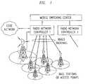
- a traditional wireless access networkconsists of a number of base stations (access points) connected to a centralized controller (radio network controller/base station controller) using wired links (copper, co-axial cable, fiber).
- the radio network controllersare connected back to circuit-switches or packet-data routers which in turn connect to the wired telecommunications infrastructure (the core network).
- This traditional, hierarchical networkis shown in FIG. 1 .
- a wired connectionis usually required from each base station to the controller and then onwards to the core network.
- these wired linksare T1, E1, Ethernet or fiber links.
- specialized dedicated line-of-sight microwave linksare employed that use separate spectrum. Implementation of such dedicated backhaul connections is usually expensive.
- One such alternativeis to somehow provision wireless backhaul links between the base stations themselves and thereby provide the backhaul communications path.
- infrastructure nodesbase stations or access points
- each of the large service provider networks todayconsist of in excess of 50,000 cells sites at which base stations are located. It is not unrealistic to expect such numbers to grow by a factor of 100 to about 5 million. Such large number of base stations will be needed to ensure truly ubiquitous data coverage. It is also likely that many of these new access points cannot be easily supported with a wired backhaul to the core network.
- the inventorsdisclose herein a methodology for routing packets via an access terminal (AT) between base stations (access points), using wireless technology.
- the access-terminal routing capabilitymay be used to provide a wireless, meshed backhaul between base stations using existing wireless-access resources (time, bandwidth, code-space, power), protocols, and base station infrastructure.
- existing wireless-access resourcestime, bandwidth, code-space, power
- protocolsand base station infrastructure.
- an ATcan serve as a “proxy router” when called upon to do so.
- the ability to use the AT to route packets between base-stationsprovides added flexibility to configure and control base-stations and also redundancy in case existing backhaul is congested or broken.
- access terminal routing capabilityprovides network integration and more efficient resource allocation in frequency division duplex (FDD) wireless systems, while keeping the access terminal cost and complexity low.
- FDDfrequency division duplex
- TDDtime division duplex
- an all-wireless network(with no wired or specialized wireless backhaul) may be realized where air-interface resources are shared in a dynamic manner between the access and backhaul functions (on-demand and as-needed) using a single set of access protocols.
- Several access terminalsmay be used concurrently to achieve high data-rate backhaul.
- a service modelis described whereby access terminal owners (customers of wireless network operators) negotiate use of their devices to provide connectivity services to network operators by linking base stations via their devices.
- new extensions to current EVDO air-interface standardsthat enable AT routing capability are provided.
- the current EVDO standardswould be enhanced with additional air-interface resource (power control, time and frequency) management and coordination.
- the AT routing and relaying capability provided by the inventionmay be extended to new OFDM based air-interface technologies being consider for 4 th generation cellular standards such as LTE; UMB and WiMAX.
- FIG. 1provides a schematic illustration of an hierarchical wireless network
- FIG. 2schematically illustrates a packet data wireless access network
- FIG. 3illustrates a second base station acting as a relay for a first base station
- FIG. 4schematically illustrates a 2-tier mesh network
- FIG. 5schematically illustrates a flat 1-tier mesh network
- FIG. 6shows the various network elements that form a mesh network in the 802.11s standard
- FIG. 7provides a schematic depiction of an exemplary IEEE 802.16 based mesh network
- FIG. 8provides a schematic depiction of a network provided under the 802.16j (Mobile Multi-hop Radio) standard
- FIG. 9provides a schematic depiction of a network provided under the 802.15.x (Wireless Personal Area Networks) standard
- FIG. 10schematically illustrates the operation of an access terminal according to the method of the invention.
- FIG. 11shows the path traversed along a typical protocol stack in a relay operation according to the invention.
- FIG. 12illustrates, schematically and functionally, the underlying air-interface links and a high level information exchange between the AT routers and communicating base stations in the method of the invention.
- FIG. 13provides a schematic illustration of the basic network elements for the invention.
- FIG. 14provides a schematic illustration of an exemplary routing network implemented by the invention
- FIG. 15shows an illustration of an exemplary mesh network capability implemented by the invention.
- FIG. 16provides a schematic illustration of another exemplary routing network implemented by the invention
- FIG. 17schematically illustrates a network device combining functions of basic Type A and Type B network devices, also termed device Type C.
- FIG. 18provides a schematic illustration of a further exemplary routing network implemented by the invention
- FIG. 19schematically depicts in-building coverage extension implemented via the methodology of the invention
- FIG. 20schematically depicts an exemplary case of range and coverage extension using a single-hop implemented via the methodology of the invention
- FIG. 21schematically depicts a further implementation of range extension using Type C device as an intermediate relay via the methodology of the invention
- FIG. 22schematically depicts an alternative further implementation of range extension via the methodology of the invention
- FIG. 23schematically depicts an exemplary case of temporary communications coverage being provided via the methodology of the invention
- FIG. 24provides a schematic depiction of coordination among a macro cell and a pico or femto cell for auto-configuration and RF optimization using the methodology of the invention is applicable
- FIG. 25illustrates fault/performance management functions using the methodology of the invention in a fixed infrastructure case
- FIG. 26illustrates fault/performance management using the methodology of the invention in a mobile case
- Wireless access networksare evolving towards packet-switching (as opposed to circuit switching) and end-to-end use of the Internet protocol.
- Such an evolved packet data wireless access networkis shown in FIG. 2 .
- the evolved access networkconsists of IP-addressable base stations connecting to the core packet data network via edge routers (known as gateways).
- the interfaces between the evolved base stations and the gatewaysare IP interfaces.
- Other signaling and control entities within the access network(that may either be integrated into the base stations or be stand-alone network elements) also use IP protocols.
- Entities in the core network that support the operation of the access networkinclude AAA servers and IMS (IP Multimedia sub-system) nodes to deliver multimedia services over the IP-based network.
- IMSIP Multimedia sub-system
- the top branch in FIG. 2shows elements of EVDO networks that are currently deployed.
- Evolved access terminalsare IP addressable and the evolved air-interface protocols support internet protocols between these access terminals and the base stations.
- a mesh networkis one where the network nodes are connected (or can be connected) along multiple paths.
- a relayis specialized network equipment that transfers data over-the-air from one entity to the other (say a base station to an access terminal and vice-versa).
- FIG. 3shows an example that depicts BS 2 acting as a relay of BS 1 .
- Inter BS communicationmay be via a wired backhaul or a line-of-sight (LOS) microwave wireless link.
- LOSline-of-sight
- Mesh networksfall under two major categories: a 2-tier mesh network and a flat, 1-tier mesh network.
- the first layerforms an interconnected set of mesh base stations.
- the access terminalsdo not have mesh capabilities.
- the flat 1-tier mesh networks shown in FIG. 5all terminals are capable of being a mesh node. There is no distinction between a base-station and an access terminal. Each node functions as both a base-station and an access terminal.
- Wireless mesh and relay networksexist today as specified in IEEE 802 standards. These standards originated as extensions to the existing wireless LANs (802.11), wireless PANs (802.15) and in one case as an extension to wireless WAN (802.16). Integrating these 802 standards into existing, or emerging, cellular network standards such as UMB, EVDO, LTE etc as an overlay leads to a very difficult operational and network management undertaking. Such an integration would require complex multi-standard handsets, difficult hand-off protocols, and very complex interworking between various network elements that follow different standards.
- CSMA/CACarrier sense multiple access with collision avoidance
- TDMtime-division-multiplexing
- TDDtime-division-duplex
- CSMA/CAis simply a listen-before-you-transmit mechanism. Each mesh point or access terminal waits to make sure that the channel is not being used by other mesh points before transmitting.
- the CSMA/CA protocolspecifies how to deal with any collisions in case two mesh points happen to transmit at the same time.
- the CSMA/CAhas the advantage of resource allocation not being controlled from a centralized node leading to easy deployment. The downside is that the RF resources are inefficiently used.
- TDDtime division duplexing
- a centralized scheduler based resource allocationeither in base stations or special gateways, coordinates which network element transmits and receives at what time slots based on control information exchange between the various mesh points.
- the centralized resource managementis simpler to implement, but slow and inefficient. Many distributed schemes, albeit much more complex, are under consideration as well.
- FIG. 6shows the various network elements that form a mesh network. The properties of those elements are outlined below.
- Throughput for 802.11scan be very low due to collision based access and data transfer mechanism.
- FIG. 7shows an example of IEEE 802.16 based mesh network.
- the 802.16 mesh networkconsists of a Base Station (BS) and subscriber stations (SSs).
- the BSserves as a gateway to external network.
- Each SScan communicate with the BS and also with other SS.
- the coordination function between mesh nodesis scheduling based and slotted. Control and data are sent on the same channel, but using different time sub-frames. Both centralized and distributed scheduling mechanisms are specified in the standards to provide collision free transmission of control and data.
- the mesh BShandles all the uplink (traffic goes from SSs to mesh BS) and downlink (traffic from mesh BS to SSs).
- all SSsare peers and establish a handshaking protocol for reserving time slots to transmit between SSs. Slots are reserved by exchanging control messages between mesh nodes. TDD is used to share the channel between uplink and downlink.
- Each active mesh node(BS and SS) broadcasts network configuration advertisements. Any new SS that wishes to join the mesh scans for the advertised mesh network configuration messages. Upon selecting the appropriate mesh node to attach to (called a sponsor), it registers with the network via the sponsoring SS and becomes part of the mesh.
- the 802.16j MMR (Mobile Multi-hop Radio) standardis primarily focused as a relay function extension to 802.16 standards and is depicted in FIG. 8 . Properties of the elements of that configuration are outlined below.
- Direct BS to MS communicationuses the 802.16 TDD air interface standards with no changes.
- BS to RS communicationis also based on TDD with TDM scheduling of downlink (DL) and uplink (UL).
- the time slotsare divided further into control traffic and mesh traffic. Scheduling and routing messages are exchanged through the control segment time-slots before transmitting bearer data on mesh traffic time-slots.
- RS to RS communication protocolsalso utilize the same mechanism as the BS to RS protocols.
- Centralized BS scheduling and routingis considered as the default option for easier implementation.
- the clientsare both consumers and nodes of an ad hoc mesh network.
- the “routers”may be fixed or mobile. No infrastructure BS or AP is involved.
- a wireless PAN PICONETconsists of several components.
- the basic componentis the DEV (device).
- One DEVis required to assume the role of the piconet coordinator (PNC) of the piconet.
- the PNCprovides the basic timing for the piconet with a beacon. Additionally, the PNC manages the quality of service (QoS) requirements, power save modes and access control to the piconet.
- QoSquality of service
- Devices in a piconetcan communicate on a peer-to-peer basis.
- An Integrated Mesh/Relay/Radio-Access networkallows for the use of a single air-interface access protocol over a single, shared air-interface to provide all meshing and relaying functions among the access terminals and base stations of the wireless network while also supporting wireless mobile access.
- the access terminaltakes on a dual function.
- the access terminalsources (or is the final destination of) the information being communicated over the air between it and a base station, the link is being used for access.
- the access terminalis the recipient of the information (from another base station) that it then communicates over the air to a base station, it is performing a mesh/backhaul/relay function using the very same air-interface resources and access protocols.
- the access terminalis augmented, according to the invention, with the following capabilities:
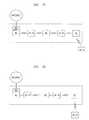
- FIG. 10Operation of the access terminal in the relay mode as transferring data/signaling/control information between surrounding base stations is schematically illustrated in FIG. 10 .
- the data stream marked 1 , 1 ′is communicated from BS 1 to BS 2 via the AT Router.
- the data stream marked 2 , 2 ′is communicated from BS 2 to BS 1 via the AT Router.
- the bidirectional data stream marked 3subsumes streams 1 , 1 ′, 2 , 2 ′ and shows the end-to-end communication path that is being enabled by the AT Router.
- FIG. 11shows the path traversed along the protocol stack by the information starting from source BS via the routing AT to the destination BS.
- Ultra Mobile Broadband (UMB) air interface(as standardized by 3GPP2 standards development organization) it should be understood that the invention is not in any way limited to this illustrative case and can easily be extended to EVDO standards based on CDMA technology and other OFDMA standards such as LTE and WiMAX.
- the air-interface resource set-up and allocation procedurescan be done co-operatively by base stations, using the information reported and relayed by the AT router. Another option is a decision process where the resource consumption decisions are made by the AT router itself, based on the resource constraints conveyed by the base stations to the AT router and the router's own constraints.
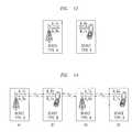
- the basic network modelis one where there are only two device types which can be designated as Dev Type A and the other as Dev Type B. This model is illustrated in FIG. 13 .
- the network operation for the basic network modelis defined by the following rules:
- Dev Type A operationis complementary to Dev Type B
- a device typedoes not communicate directly over the air (i.e. without any intermediate nodes) with another device of the same type.
- Dev Type A Dev Type B Dev Type ATwo devices of Type A would communicate, for example, via a Dev Type B: Dev Type A (1) Dev Type B Dev Type A (2).
- Dev Type ADev Type A
- Dev Type B Dev Type ADev Type A
- any type of networktraditional point-to-multipoint cellular networks, mesh or relay—can be devised using just these two types of network elements of opposite Tx/Rx polarity. An exemplary such case is illustrated in FIG. 14 .
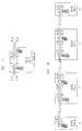
- FIG. 15An illustration of mesh network capabilities is depicted in FIG. 15 .
- the ability to relay or route messages from source base station to destination base station via multiple independent linksis shown via the basic network model using Type A (base station), and Type B (Access terminal) devices.
- this systemallows any two base stations to communicate with each other using intermediate ATs and BSs. Also, any two ATs are able to communicate with each other using only the services of intermediate BSs and ATs (i.e. without the use of any wired of specialized wireless backhaul).
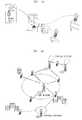
- Such an exemplary routing arrangementis illustrated in FIG. 16 .
- a Device Type Ccan be derived by integrating two devices of Type A and B as shown in FIG. 17 .
- the wired interface between Device Types A and B within Device Type Ccan be the same as the wireless interface.
- Devices of either Type A or Bcan communicate with Dev Type C as shown in FIG. 18 . Interference between the constituent device types in Dev Type C can be mitigated by the use of interference cancellation techniques since the information content of the interfering signal is known a priori. In essence, this device acts as a Tx/Rx inverter.
- the basic network model of the inventionusing combinations of ATs and BSs to provide network connectivity—can be applied in a wide variety of applications, several of which are described below as further embodiments of the invention. It should be understood, however, that the described embodiments are meant only to be exemplary of the utility of the invention, and should not be construed as in any way limiting the scope of the invention usage-models that may be enabled with a combination of BS and AT-Router. A few of the categories are listed below:
- a relay and mesh network established among wireless access terminals and base stationsis readily applied to the provision of range and coverage extension functions. Two important applications of such functions are described below as further invention embodiments.
- FIG. 19shows a device type C being used to provide backhaul free coverage inside a home.
- a particularly important application of the AT routing methodology of the inventionis the case of providing range extension using a base station peripheral to the core wireless network, where the provision of a dedicated backhaul for the BS would be difficult to implement and or prohibitively expensive.
- An exemplary infrastructure relay for coverage extensionis illustrated in FIG. 20 .
- LOSline-of-sight
- NLOSnon line-of-sight
- Completely wireless connections between BSs and AT-Routersare depicted in FIG. 21 . This option is useful when BS's do not have line-of-sight (LOS) transmission.
- LOSline-of-sight
- a co-located, and possibly wired together, BS and AT-Router combination (referred to previously as Type C device) that provides a link between relay stationsis illustrated in FIG. 22 . This option is useful when LOS conditions do present themselves during deployment.
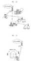
- the AT Router methodology of the inventionalso can be applied for establishing communication coverage for temporary communication requirements, such as emergency and special event communications coverage.
- This caseis illustrated in FIG. 23 , which shows a combination of BSs, mounted on vehicles, and AT-Routers being used to set up quick network coverage for an emergency requiring communications among disparate units and or services. Similar methods can be adopted for special locations and events like sports meets, conventions etc which are infrequent and do not warrant permanent and expensive fixed assets.
- the AT-Router methodology of the inventionprovides exactly such a mechanism. Due to its ability to provide connectivity between a BS and femto/pico cells, the AT Router can readily provide the needed coordination. The AT-Router is used to provide signaling and control for auto-configuring and optimizing the femto cells.
- AT-Routersmay also be used for RF optimization when new BS's are being added to the network.
- the coverage of new BS's or new carriershave to be adjusted in relation to its neighbors.
- the AT-Routercommunicate simultaneously with two neighboring base-stations, they can cooperate, coordinate and fine tune their RF coverage, handoff and neighbor list parameters easily in real-time.
- Wireless networks operatorsincur large operational expenses (OPEX) to perform many OA&MP activities which include fault and performance management amongst other activities. Faults and degraded network performance contributes to reduced availability and reliability metrics. Availability, reliability, time-to-respond during emergencies and faults, and associated operational expense, are accordingly key concerns for service providers and network operators.
- the AT router of the inventionprovides a cost effective alternative for fault and performance monitoring.
- the ability to monitor service coverage and quality in real time provided by the AT Routercan be a key competitive advantage to service providers.
- Two possible deployment scenariosare contemplated: (1) a fixed infrastructure case and (2) a mobile case.
- the fixed infrastructure casecontemplates AT-routers owned by service providers that are placed in strategic locations for the purpose of RF network monitoring, surveillance, reporting measurements and alarms. These fixed AT-Routers can be programmed to act as sensors, either continuously, intermittently or on demand and report back key AT measured performance indicators. An illustration of an exemplary fixed infrastructure arrangement is shown in FIG. 25 . One option for this case is to use mobile AT-Routers to report observations and also be used as a conduit to trouble-shoot malfunctioning base stations.
- the mobile casecontemplates AT routers that are highly mobile and the duration of routing capability is short. Such highly mobile ATs may be used for short request-response and querying type of operations which result in a few kilobytes of data transfer at each instance.
- An illustration of an exemplary mobile arrangementis shown in FIG. 26 .
- a messagemay be sent to a base-station to run specific self-diagnostic tests and respond with results. This may only require a few messages and a small amount of data transfer.
- the AT Router methodology of the inventionis extended to subscriber owned and operated ATs.
- the ATin order to make use of an AT to provide the described routing services (and enable base station meshing/backhaul), the AT is leveraging its favorable location, i.e. the fact that its current location enables it to transmit and receive packets reliability between a set of base stations.
- Such locationsmay be subscribers' residences or work places, i.e. locations that would not generally be accessible to a service provider for installing additional base stations to extend coverage.
- the AT owner/subscribermay be in a position to use its AT for providing a routing service to the network operator or service provider.
- the service model embodiment of the inventionis directed to a means by which the consumer is compensated by the service provider for providing connectivity services to the service provider. The compensation could include payments or credits towards future use of wireless access service.
- Compensation to the consumercan be negotiated either as part of his service contract (i.e. corresponding to the duration of time the AT is at the customer's residence and therefore available as a router) or during the actual time that the routing service is provided.
- ATscan either advertise their rates for routing or base stations can indicate the offered rates for routing, with a willing AT and a willing BS agreeing to accept offered or negotiated terms for a given routing application/duration.
Landscapes
- Engineering & Computer Science (AREA)
- Computer Networks & Wireless Communication (AREA)
- Signal Processing (AREA)
- Mobile Radio Communication Systems (AREA)
Abstract
Description
- Mesh Point (MP): establishes peer-to-peer links with other MPs.
- Mesh Access Points (MAP=MP+AP): MP function co-located with Access Point (AP)
- Mesh Portal Points (MPP=MP+Portal): Gateway functionality of MP co-located with network element, or portal, where data enters and exits the mesh.
- STA (Stations): End user access terminals, which is outside of the mesh.
- The PHY and MAC layer communication between STA and MAP (MP+AP) remains unchanged (802.11a/b/g). The access mechanism remains CSMA/CA. The protocol relies on “listen before you send” mechanism—a collision avoidance scheme.
- The communication between MPs retain the same CSMA/CA paradigm of 802.11a/b/g.
Additional LAYER 2 route discovery and forwarding specifications are specified in the MAC layer enhancements for MESH operation. - Routing is based on HWMP (Hybrid Wireless Mesh Protocol) which is a hybrid of Radio Metric AODV (ad-hoc distance vector)+Tree based routing.
- Radio Aware OLSR (on-demand link state routing) is optional
- BS: Base Station, requiring an MMR enhancement is needed.
- RS: Relay Station. Acts as a BS to an MS and an MS to BS.
- Types of RS: Fixed (infrastructure), Nomadic (special events, indoor), Mobile (trains)
- MS/SS: Mobile Station/Subscriber station.
- Conventional 802.16 SS/MS only.
- Mobiles are outside the relay network.
- 802.15.1 Bluetooth-TDM, Master/Slave, not contention based
- 802.15.3 for high rate/high bandwidth applications-Ultra wide band (UWB) based.
- 802.15.4 for low rate sensor networks (like Zigbee).
- Advertisement by it of its routing capabilities over-the-air to base stations in its vicinity (radio range);
- Negotiation between it and the base station on the duration and Quality of Service (bandwidth offered, latency) of the routing service;
- Transfer of IP layer data streams received on one downlink to another uplink;
- Maintain radio connectivity, i.e. ability to send and receive packets reliably, with multiple base stations on both downlink and uplink.
- The AT Router monitors the downlink pilot channels from base stations in its vicinity to track the downlink channel from each of these base stations to itself and reports channel quality measurements;
- The base stations report, over the air, a measure of the received (pilot) signal strength from the AT Router that enables the AT Router to track the quality of its channel to each of these base stations;
- The AT Router estimates the supportable data rates on each uplink-downlink channel-pair;
- The BS broadcasts router solicitations to discover AT Routers that can act as routers and forward packets on its behalf towards the intended destination (or the first point of connectivity to the wired network)—this step may precede the initiation of a call to the BS.
- AT Routers in the vicinity of this BS advertise their ability to route packets, the BSs between which they are able to route packets, and the supportable data rates to and from these BSs. An AT Router may also advertise autonomously, without a solicitation request.
- The BS and AT Router negotiate a duration (lease time) and quality of service (bandwidth, latency) for the provided routing service. When negotiation with the base stations is completed, the AT requests and receives appropriate resource allocations (sub-carriers to be used, transmission times etc) from the base stations to and from which data is being routed;
- The MAC and RLC (radio link control) layers ensure reliable reception of packets through H-ARQ RLC re-transmission protocols, respectively.
- At end of the “lease time” AT Router ends routing service and releases assigned air-interface resources.
- a) For example, in a Frequency Division Duplex (FDD) System, the transmit and receive frequencies of these two device types are flipped. In the case illustrated in
FIG. 13 , transmit frequency A_Tx is equal to receive frequency B_Rx and frequency B_Tx is equal to frequency A_Rx for effective simultaneous transmission and reception to occur. - b) In Time Division Duplex (TDD), by contrast, a single frequency is used and hence simultaneous transmission and reception cannot take place. Therefore, the transmit and receive time-slots are flipped. Each device must listen while the other is talking for establishing any reasonable communication between them. If both devices attempt to transmit at the same time, a collision occurs and no effective communication takes place. Again referring to
FIG. 13 , when device type A is transmitting at time-slot A_Tx, the receiver in device type B must listen to it at the same time B_Rx. Similarly, when device type B transmits at time slot B_Tx, then device type A must listen to it at the same time-slot A_Rx.
- a) For example, in a Frequency Division Duplex (FDD) System, the transmit and receive frequencies of these two device types are flipped. In the case illustrated in
- It is much simpler to build out a mesh/relay network with the existing two network elements (i.e. BS and AT) with minimal changes to existing standards or device complexity.
- It is expensive to have FDD mesh devices that can serve both as a BS and AT, as considered in the IEEE 802 systems.
- The resource allocations in FDD systems are not collision based and hence make more efficient use of spectrum. The BS makes resource decisions based on instantaneous demands and available resources. This allows for dynamic resource sharing between the AT's own communication needs and the need to reserve resources for backhaul.
- Using separate IEEE 802 based mesh networks intertwined with cellular networks is operationally difficult to deploy.

Claims (16)
Priority Applications (15)
| Application Number | Priority Date | Filing Date | Title |
|---|---|---|---|
| US12/286,417US8520559B2 (en) | 2008-04-02 | 2008-09-30 | Method for routing via access terminals |
| US12/319,094US8675550B2 (en) | 2008-06-14 | 2008-12-31 | Method for backhaul interference management with access terminal router |
| US12/319,117US20090279461A1 (en) | 2008-05-12 | 2008-12-31 | Access terminal router implementation on enhanced HRPD |
| US12/319,151US20090285133A1 (en) | 2008-05-16 | 2008-12-31 | Method for over-the-air base station management via access terminal relay |
| PCT/US2009/001708WO2009123677A1 (en) | 2008-04-02 | 2009-03-18 | Method for routing via access terminals |
| KR1020107024348AKR101302631B1 (en) | 2008-04-02 | 2009-03-18 | Method for Routing Through Access Terminals |
| JP2011502933AJP5147988B2 (en) | 2008-04-02 | 2009-03-18 | Method for routing through an access terminal |
| CN200980112128.4ACN101983535B (en) | 2008-04-02 | 2009-03-18 | Via the method for the route that accesses terminal |
| EP09729162.9AEP2263413B1 (en) | 2008-04-02 | 2009-03-18 | Method for routing via access terminals |
| PCT/US2009/003556WO2009151641A2 (en) | 2008-06-14 | 2009-06-12 | Method for backhaul interference management with access terminal router |
| JP2011513508AJP5345683B2 (en) | 2008-06-14 | 2009-06-12 | Method for backhaul interference management using access terminal router |
| KR1020107027795AKR101267300B1 (en) | 2008-06-14 | 2009-06-12 | Method for backhaul interference management with access terminal router |
| CN201310689551.9ACN103747501B (en) | 2008-06-14 | 2009-06-12 | Method for eliminating relay transmission interference and wireless communication system |
| EP09762937.2AEP2289279B1 (en) | 2008-06-14 | 2009-06-12 | Method for backhaul interference management with access terminal router |
| CN2009801223964ACN102067698A (en) | 2008-06-14 | 2009-06-12 | Method of backhaul interference management using an access terminal router |
Applications Claiming Priority (2)
| Application Number | Priority Date | Filing Date | Title |
|---|---|---|---|
| US7270408P | 2008-04-02 | 2008-04-02 | |
| US12/286,417US8520559B2 (en) | 2008-04-02 | 2008-09-30 | Method for routing via access terminals |
Related Child Applications (3)
| Application Number | Title | Priority Date | Filing Date |
|---|---|---|---|
| US12/319,094Continuation-In-PartUS8675550B2 (en) | 2008-06-14 | 2008-12-31 | Method for backhaul interference management with access terminal router |
| US12/319,151Continuation-In-PartUS20090285133A1 (en) | 2008-05-16 | 2008-12-31 | Method for over-the-air base station management via access terminal relay |
| US12/319,117Continuation-In-PartUS20090279461A1 (en) | 2008-05-12 | 2008-12-31 | Access terminal router implementation on enhanced HRPD |
Publications (2)
| Publication Number | Publication Date |
|---|---|
| US20090252088A1 US20090252088A1 (en) | 2009-10-08 |
| US8520559B2true US8520559B2 (en) | 2013-08-27 |
Family
ID=41133192
Family Applications (1)
| Application Number | Title | Priority Date | Filing Date |
|---|---|---|---|
| US12/286,417Expired - Fee RelatedUS8520559B2 (en) | 2008-04-02 | 2008-09-30 | Method for routing via access terminals |
Country Status (6)
| Country | Link |
|---|---|
| US (1) | US8520559B2 (en) |
| EP (1) | EP2263413B1 (en) |
| JP (1) | JP5147988B2 (en) |
| KR (1) | KR101302631B1 (en) |
| CN (1) | CN101983535B (en) |
| WO (1) | WO2009123677A1 (en) |
Cited By (4)
| Publication number | Priority date | Publication date | Assignee | Title |
|---|---|---|---|---|
| US20140244842A1 (en)* | 2013-02-28 | 2014-08-28 | Elisha J. Rosensweig | Allocation of resources based on constraints and conflicting goals |
| US9781738B2 (en) | 2013-02-07 | 2017-10-03 | Idac Holdings, Inc. | Physical layer (PHY) design for a low latency millimeter wave (MMW) backhaul system |
| US10511990B1 (en) | 2017-03-16 | 2019-12-17 | Sprint Communications Company L.P. | Wireless relay backhaul over visitor wireless user devices |
| US11026285B2 (en) | 2019-04-03 | 2021-06-01 | At&T Intellectual Property I, L.P. | Systems and methods for establishing network connections |
Families Citing this family (62)
| Publication number | Priority date | Publication date | Assignee | Title |
|---|---|---|---|---|
| US8520559B2 (en) | 2008-04-02 | 2013-08-27 | Alcatel Lucent | Method for routing via access terminals |
| US8718696B2 (en)* | 2008-05-13 | 2014-05-06 | Qualcomm Incorporated | Transmit power selection for user equipment communicating with femto cells |
| US8711786B2 (en)* | 2008-05-13 | 2014-04-29 | Qualcomm Incorporated | Autonomous downlink code selection for femto cells |
| US8725083B2 (en)* | 2008-05-13 | 2014-05-13 | Qualcomm Incorporated | Self calibration of downlink transmit power |
| US8737317B2 (en)* | 2008-05-13 | 2014-05-27 | Qualcomm Incorporated | Autonomous carrier selection for femtocells |
| US8472366B2 (en)* | 2008-09-22 | 2013-06-25 | Research In Motion Limited | Network-relay signaling for downlink transparent relay |
| US8971263B2 (en)* | 2008-10-20 | 2015-03-03 | Telefonaktiebolaget L M Ericsson (Publ) | QoS management for self-backhauling in LTE |
| US20100103869A1 (en)* | 2008-10-28 | 2010-04-29 | Nortel Networks Limited | Transferring data in a mobile telephony network |
| US8964706B2 (en)* | 2008-11-05 | 2015-02-24 | Nokia Siemens Networks Oy | Communication method and system |
| CN102217355A (en)* | 2008-11-07 | 2011-10-12 | 京瓷株式会社 | Wireless communication system, radio base station and wireless communication method |
| US8848594B2 (en)* | 2008-12-10 | 2014-09-30 | Blackberry Limited | Method and apparatus for discovery of relay nodes |
| US8402334B2 (en) | 2008-12-17 | 2013-03-19 | Research In Motion Limited | System and method for hybrid automatic repeat request (HARQ) functionality in a relay node |
| US8040904B2 (en)* | 2008-12-17 | 2011-10-18 | Research In Motion Limited | System and method for autonomous combining |
| US8311061B2 (en) | 2008-12-17 | 2012-11-13 | Research In Motion Limited | System and method for multi-user multiplexing |
| US8335466B2 (en) | 2008-12-19 | 2012-12-18 | Research In Motion Limited | System and method for resource allocation |
| US8446856B2 (en) | 2008-12-19 | 2013-05-21 | Research In Motion Limited | System and method for relay node selection |
| US8265128B2 (en) | 2008-12-19 | 2012-09-11 | Research In Motion Limited | Multiple-input multiple-output (MIMO) with relay nodes |
| US8855048B2 (en)* | 2009-02-27 | 2014-10-07 | Broadcom Corporation | Method and system for peer-to-peer cellular communications |
| US8509711B1 (en) | 2010-01-11 | 2013-08-13 | L-3 Communications Corp. | Wireless terminals, systems, and methods using interlaced diplexers |
| FR2959634B1 (en)* | 2010-04-30 | 2016-11-04 | Sagemcom Energy & Telecom Sas | METHOD FOR CONFIGURING A DEVICE OF A STRUCTURED RADIO FREQUENCY COMMUNICATION NETWORK BY RECEIVING A FRAME |
| FR2959635B1 (en)* | 2010-04-30 | 2012-11-02 | Sagemcom Energy & Telecom Sas | METHOD FOR PROPAGATION OF AN EVENT OCCURRING ON A DEVICE OF A STRUCTURED RADIO FREQUENCY COMMUNICATION NETWORK |
| GB2480689B (en) | 2010-05-28 | 2013-05-08 | Toshiba Res Europ Ltd | Radio resource management in femtocells |
| FR2962295A1 (en)* | 2010-06-30 | 2012-01-06 | France Telecom | METHOD OF ESTABLISHING A CONNECTION BETWEEN TWO COMMUNICATION EQUIPMENTS |
| US8948599B2 (en) | 2010-07-28 | 2015-02-03 | Dharma P. Agrawal | Femtocell-based mesh network with optical interconnect for 4-G multimedia communications |
| GB2484278A (en) | 2010-10-04 | 2012-04-11 | Airspan Networks Inc | Suppressing co-channel interference in dependence upon probabilities of establishing a link between a base station and a terminal via resource blocks |
| GB2484280B (en) | 2010-10-04 | 2014-10-08 | Airspan Networks Inc | Apparatus and method for controlling a wireless feeder network |
| GB2484279B (en) | 2010-10-04 | 2014-11-12 | Airspan Networks Inc | Apparatus and method for controlling a wireless feeder network |
| JP5598261B2 (en)* | 2010-11-02 | 2014-10-01 | 富士通株式会社 | Radio channel relay method, radio base station apparatus and radio terminal |
| WO2012063849A1 (en)* | 2010-11-09 | 2012-05-18 | 京セラ株式会社 | Communication system, wireless base station, and communication control method |
| KR20120071924A (en)* | 2010-12-23 | 2012-07-03 | 한국전자통신연구원 | Method for supproting node mobility in wireless mesh network |
| JP5601211B2 (en)* | 2011-01-14 | 2014-10-08 | 富士通株式会社 | Wireless communication system, wireless access station, and communication method |
| KR101820678B1 (en)* | 2011-02-22 | 2018-01-22 | 삼성전자주식회사 | Apparatus and method for hierarchical rate splitting in hierarchical cell communication system |
| US8509787B2 (en)* | 2011-07-07 | 2013-08-13 | Cygnus Broadband, Inc. | Communications base station with decision function for distributing traffic across multiple backhauls |
| US8989091B2 (en)* | 2011-07-15 | 2015-03-24 | Telefonaktiebolaget L M Ericsson (Publ) | Dynamic enablement of M2M services over 3GPP access networks |
| US20130114571A1 (en)* | 2011-11-07 | 2013-05-09 | Qualcomm Incorporated | Coordinated forward link blanking and power boosting for flexible bandwidth systems |
| EP2901632B1 (en)* | 2012-09-29 | 2018-05-30 | Assia Spe, Llc | Optimized control system for aggregation of multiple broadband connections over radio interfaces |
| US9480106B2 (en)* | 2012-11-28 | 2016-10-25 | T-Mobile Usa, Inc. | Inter-base station logical interface communication using relay devices |
| WO2014092468A1 (en)* | 2012-12-12 | 2014-06-19 | 엘지전자 주식회사 | Method and apparatus for transmitting backhaul link information |
| KR101980132B1 (en)* | 2013-04-26 | 2019-08-28 | 삼성전자주식회사 | Method and apparatus for allocating resources to perform communications between base stations |
| CN104185183A (en)* | 2013-05-20 | 2014-12-03 | 中兴通讯股份有限公司 | Method for realizing D2D communication and system thereof |
| CN103607345B (en)* | 2013-11-21 | 2018-01-05 | 浙江宇视科技有限公司 | A kind of monitor node establishes the method and system of routing iinformation |
| JP6254467B2 (en)* | 2014-03-20 | 2017-12-27 | Kddi株式会社 | Terminal apparatus, base station apparatus, usage architecture determination method, and computer program |
| JP2015216564A (en)* | 2014-05-13 | 2015-12-03 | 日本無線株式会社 | Communication system |
| US10004050B2 (en)* | 2014-05-22 | 2018-06-19 | Qualcomm Incorporated | Method and apparatus for synchronizing and propagating state information in wireless downlink/uplink |
| EP3142420B1 (en) | 2014-05-26 | 2019-07-24 | Huawei Technologies Co., Ltd. | Wireless backhaul method, mobile terminal, and system |
| JP2016005242A (en)* | 2014-06-19 | 2016-01-12 | 日本電気株式会社 | Radio communication system, base station, communication method, and program |
| CN104243266A (en)* | 2014-09-18 | 2014-12-24 | 小米科技有限责任公司 | Method and device for network access |
| EP3806397B1 (en) | 2014-12-04 | 2023-11-22 | Assia Spe, Llc | Method and apparatus for predicting successful dsl line optimization |
| US10159035B2 (en)* | 2015-03-11 | 2018-12-18 | Qualcomm Incorporated | Methods for backhaul operations in millimeter wave networks |
| GB2539722B (en) | 2015-06-25 | 2021-10-13 | Airspan Ip Holdco Llc | Bearing calculation |
| GB2539735A (en) | 2015-06-25 | 2016-12-28 | Airspan Networks Inc | Sub-sampling antenna elements |
| GB2539727B (en) | 2015-06-25 | 2021-05-12 | Airspan Ip Holdco Llc | A configurable antenna and method of operating such a configurable antenna |
| GB2539731B (en) | 2015-06-25 | 2021-08-04 | Airspan Ip Holdco Llc | Quality of service in wireless backhauls |
| GB2539730B (en) | 2015-06-25 | 2021-04-07 | Airspan Ip Holdco Llc | Node role assignment in networks |
| GB2539732A (en) | 2015-06-25 | 2016-12-28 | Airspan Networks Inc | A configurable antenna and method of operating such a configurable antenna |
| EP3314963B1 (en) | 2015-06-25 | 2019-04-24 | Airspan Networks Inc. | Managing external interference in a wireless network |
| US10009260B2 (en)* | 2015-06-30 | 2018-06-26 | Qualcomm Incorporated | Management of network routing domains in communication networks |
| JP6163181B2 (en)* | 2015-08-21 | 2017-07-12 | 株式会社Nttドコモ | User terminal, radio base station, and radio communication method |
| JP6870260B2 (en)* | 2016-09-27 | 2021-05-12 | 株式会社リコー | Communication systems, communication devices, communication management methods, and programs |
| WO2018072833A1 (en)* | 2016-10-20 | 2018-04-26 | Telefonaktiebolaget Lm Ericsson (Publ) | Method and apparatuses for attaching a radio base station to a core network node |
| WO2019163645A1 (en)* | 2018-02-22 | 2019-08-29 | Kddi株式会社 | Control device for cellular communication network in which relayed communication is performed, base station device, terminal device, control methods therefor, and program |
| CN112738885B (en)* | 2020-12-22 | 2023-06-02 | 超讯通信股份有限公司 | Method for managing small base station |
Citations (23)
| Publication number | Priority date | Publication date | Assignee | Title |
|---|---|---|---|---|
| JPH04260228A (en) | 1991-02-15 | 1992-09-16 | Matsushita Electric Works Ltd | System for measuring position of moving body |
| US6005884A (en)* | 1995-11-06 | 1999-12-21 | Ems Technologies, Inc. | Distributed architecture for a wireless data communications system |
| US6608823B1 (en) | 1998-09-18 | 2003-08-19 | Nec Corporation | CDMA mobile communication system and service area |
| WO2003101132A1 (en) | 2002-05-27 | 2003-12-04 | Ntt Docomo, Inc. | Mobile communication system, transmission station, reception station, relay station, communication path deciding method, and communication path deciding program |
| WO2004102891A1 (en) | 2003-05-15 | 2004-11-25 | Telefonaktiebolaget Lm Ericsson (Publ) | Interference cancellation in wireless relaying networks |
| JP2005117247A (en) | 2003-10-06 | 2005-04-28 | Saxa Inc | Registration method in wireless LAN system |
| US20050192037A1 (en) | 2004-01-29 | 2005-09-01 | Qualcomm Incorporated | Distributed hierarchical scheduling in an AD hoc network |
| US20060036518A1 (en)* | 2004-08-13 | 2006-02-16 | O'neill Alan | Methods and apparatus for performing resource tracking and accounting at an end node |
| US20060120436A1 (en) | 2004-12-03 | 2006-06-08 | Nec Corporation | Wireless communication system for determining the number of operation stages of interference canceller |
| US20060178149A1 (en) | 2005-02-04 | 2006-08-10 | Kamat Sandip D | Systems and methods for wireless cellular telephone routers |
| US20060221894A1 (en)* | 2005-04-04 | 2006-10-05 | Lorenzo Casaccia | Method and apparatus for management of multi-carrier communications in a wireless communication system |
| US20070060178A1 (en)* | 2005-08-22 | 2007-03-15 | Alexei Gorokhov | Segment sensitive scheduling |
| EP1830522A1 (en) | 2006-03-01 | 2007-09-05 | Broadcom Corporation | Bridging end point device supporting inter access point communication |
| US7450948B2 (en)* | 2004-01-15 | 2008-11-11 | Cingular Wireless Ii, Llc | Method and apparatus for use in provisioning resources for a backhaul link |
| US7526012B2 (en) | 2004-06-11 | 2009-04-28 | Fujitsu Limited | Interference reduction apparatus and method |
| US20090213806A1 (en)* | 2006-11-10 | 2009-08-27 | Fujitsu Limited | Wireless communication system and wireless terminal device |
| US20090232019A1 (en)* | 2008-03-12 | 2009-09-17 | Qualcomm Incorporated | Providing multiple levels of service for wireless communication |
| WO2009123677A1 (en) | 2008-04-02 | 2009-10-08 | Alcatel-Lucent Usa Inc. | Method for routing via access terminals |
| US7623863B2 (en) | 2006-08-18 | 2009-11-24 | Fujitsu Limited | System and method for adjusting connection parameters in a wireless network |
| US20100056166A1 (en)* | 2006-11-07 | 2010-03-04 | Qualcomm Incorporated | Method and Apparatus for Reinforcement of Broadcast Transmissions in MBSFN Inactive Areas |
| US7991400B2 (en)* | 2006-07-10 | 2011-08-02 | Nec Communication Systems, Ltd. | Wireless communication system, system controller, access point, station, communication control method and computer-readable medium storing communication control program |
| US8014334B2 (en) | 2003-05-19 | 2011-09-06 | Nec Corporation | Rate control method and apparatus for data packet transmission |
| US8254341B2 (en) | 2004-12-28 | 2012-08-28 | Fujitsu Limited | Control channel transmitting method, base station and terminal |
Family Cites Families (4)
| Publication number | Priority date | Publication date | Assignee | Title |
|---|---|---|---|---|
| JP4319404B2 (en)* | 2001-12-28 | 2009-08-26 | 株式会社エヌ・ティ・ティ・ドコモ | Wireless communication system, base station, relay station, mobile station, and packet transmission control method |
| US20080200200A1 (en)* | 2005-03-29 | 2008-08-21 | Ntt Docomo, Inc. | Transmission Power Control Method And Mobile Station |
| CN101283526B (en)* | 2005-10-07 | 2015-09-09 | 日本电气株式会社 | MIMO wireless communication system and method used by mobile station and multiple base stations |
| CN101043500B (en)* | 2006-06-15 | 2010-05-12 | 华为技术有限公司 | Method for Determining Reverse Data Modulation and Coding Mode and Its Access Terminal |
- 2008
- 2008-09-30USUS12/286,417patent/US8520559B2/ennot_activeExpired - Fee Related
- 2009
- 2009-03-18KRKR1020107024348Apatent/KR101302631B1/ennot_activeExpired - Fee Related
- 2009-03-18EPEP09729162.9Apatent/EP2263413B1/ennot_activeNot-in-force
- 2009-03-18CNCN200980112128.4Apatent/CN101983535B/ennot_activeExpired - Fee Related
- 2009-03-18WOPCT/US2009/001708patent/WO2009123677A1/enactiveApplication Filing
- 2009-03-18JPJP2011502933Apatent/JP5147988B2/ennot_activeExpired - Fee Related
Patent Citations (23)
| Publication number | Priority date | Publication date | Assignee | Title |
|---|---|---|---|---|
| JPH04260228A (en) | 1991-02-15 | 1992-09-16 | Matsushita Electric Works Ltd | System for measuring position of moving body |
| US6005884A (en)* | 1995-11-06 | 1999-12-21 | Ems Technologies, Inc. | Distributed architecture for a wireless data communications system |
| US6608823B1 (en) | 1998-09-18 | 2003-08-19 | Nec Corporation | CDMA mobile communication system and service area |
| WO2003101132A1 (en) | 2002-05-27 | 2003-12-04 | Ntt Docomo, Inc. | Mobile communication system, transmission station, reception station, relay station, communication path deciding method, and communication path deciding program |
| WO2004102891A1 (en) | 2003-05-15 | 2004-11-25 | Telefonaktiebolaget Lm Ericsson (Publ) | Interference cancellation in wireless relaying networks |
| US8014334B2 (en) | 2003-05-19 | 2011-09-06 | Nec Corporation | Rate control method and apparatus for data packet transmission |
| JP2005117247A (en) | 2003-10-06 | 2005-04-28 | Saxa Inc | Registration method in wireless LAN system |
| US7450948B2 (en)* | 2004-01-15 | 2008-11-11 | Cingular Wireless Ii, Llc | Method and apparatus for use in provisioning resources for a backhaul link |
| US20050192037A1 (en) | 2004-01-29 | 2005-09-01 | Qualcomm Incorporated | Distributed hierarchical scheduling in an AD hoc network |
| US7526012B2 (en) | 2004-06-11 | 2009-04-28 | Fujitsu Limited | Interference reduction apparatus and method |
| US20060036518A1 (en)* | 2004-08-13 | 2006-02-16 | O'neill Alan | Methods and apparatus for performing resource tracking and accounting at an end node |
| US20060120436A1 (en) | 2004-12-03 | 2006-06-08 | Nec Corporation | Wireless communication system for determining the number of operation stages of interference canceller |
| US8254341B2 (en) | 2004-12-28 | 2012-08-28 | Fujitsu Limited | Control channel transmitting method, base station and terminal |
| US20060178149A1 (en) | 2005-02-04 | 2006-08-10 | Kamat Sandip D | Systems and methods for wireless cellular telephone routers |
| US20060221894A1 (en)* | 2005-04-04 | 2006-10-05 | Lorenzo Casaccia | Method and apparatus for management of multi-carrier communications in a wireless communication system |
| US20070060178A1 (en)* | 2005-08-22 | 2007-03-15 | Alexei Gorokhov | Segment sensitive scheduling |
| EP1830522A1 (en) | 2006-03-01 | 2007-09-05 | Broadcom Corporation | Bridging end point device supporting inter access point communication |
| US7991400B2 (en)* | 2006-07-10 | 2011-08-02 | Nec Communication Systems, Ltd. | Wireless communication system, system controller, access point, station, communication control method and computer-readable medium storing communication control program |
| US7623863B2 (en) | 2006-08-18 | 2009-11-24 | Fujitsu Limited | System and method for adjusting connection parameters in a wireless network |
| US20100056166A1 (en)* | 2006-11-07 | 2010-03-04 | Qualcomm Incorporated | Method and Apparatus for Reinforcement of Broadcast Transmissions in MBSFN Inactive Areas |
| US20090213806A1 (en)* | 2006-11-10 | 2009-08-27 | Fujitsu Limited | Wireless communication system and wireless terminal device |
| US20090232019A1 (en)* | 2008-03-12 | 2009-09-17 | Qualcomm Incorporated | Providing multiple levels of service for wireless communication |
| WO2009123677A1 (en) | 2008-04-02 | 2009-10-08 | Alcatel-Lucent Usa Inc. | Method for routing via access terminals |
Non-Patent Citations (1)
| Title |
|---|
| Examiner's Office Letter issued in Japanese Patent Application No. 2011-513508; Inventor: Rao; Method for Backhaul Interference Management With Access Terminal Router; Dec. 13, 2012, pp. 1-7. |
Cited By (6)
| Publication number | Priority date | Publication date | Assignee | Title |
|---|---|---|---|---|
| US9781738B2 (en) | 2013-02-07 | 2017-10-03 | Idac Holdings, Inc. | Physical layer (PHY) design for a low latency millimeter wave (MMW) backhaul system |
| US20140244842A1 (en)* | 2013-02-28 | 2014-08-28 | Elisha J. Rosensweig | Allocation of resources based on constraints and conflicting goals |
| US9203705B2 (en)* | 2013-02-28 | 2015-12-01 | Alcatel Lucent | Allocation of resources based on constraints and conflicting goals |
| US10511990B1 (en) | 2017-03-16 | 2019-12-17 | Sprint Communications Company L.P. | Wireless relay backhaul over visitor wireless user devices |
| US11026285B2 (en) | 2019-04-03 | 2021-06-01 | At&T Intellectual Property I, L.P. | Systems and methods for establishing network connections |
| US11665768B2 (en) | 2019-04-03 | 2023-05-30 | At&T Intellectual Property I, L.P. | Systems and methods for establishing network connections |
Also Published As
| Publication number | Publication date |
|---|---|
| KR101302631B1 (en) | 2013-09-03 |
| WO2009123677A1 (en) | 2009-10-08 |
| EP2263413B1 (en) | 2016-05-11 |
| US20090252088A1 (en) | 2009-10-08 |
| EP2263413A1 (en) | 2010-12-22 |
| CN101983535A (en) | 2011-03-02 |
| JP5147988B2 (en) | 2013-02-20 |
| CN101983535B (en) | 2015-11-25 |
| KR20100132994A (en) | 2010-12-20 |
| JP2011518493A (en) | 2011-06-23 |
Similar Documents
| Publication | Publication Date | Title |
|---|---|---|
| US8520559B2 (en) | Method for routing via access terminals | |
| US12396062B2 (en) | Packet routing for layer-2-based sidelink relay | |
| US11470666B2 (en) | Autonomous formation for backhaul networks | |
| US7620003B2 (en) | System and method of operation of a communication network | |
| US8594678B2 (en) | Backhaul network for femto base stations | |
| JP6098850B2 (en) | Communications system | |
| US10440722B2 (en) | Mobile communications network, methods, base station, relay node and communications terminal | |
| US20130163508A1 (en) | Relay Nodes in Multi-Operator Scenario | |
| TW201911907A (en) | Techniques and apparatuses for forwarding in multi-hop wireless networks via multi-layer tunneling and centralized control | |
| EP3235300B1 (en) | Methods, base station, mobile node and relay node | |
| EP3136785B1 (en) | Data transmission method and base station | |
| KR20120139841A (en) | Method, equipment and node for determining quality of service in each section of link | |
| JP5431418B2 (en) | Wireless communication system and wireless communication method | |
| US20090279461A1 (en) | Access terminal router implementation on enhanced HRPD | |
| CN117280860A (en) | Relay selection method based on composite multi-interface load measurement | |
| Zhioua et al. | LTE Advanced relaying standard: A survey | |
| US20230388995A1 (en) | Iab hierarchical du resource configuration | |
| Schoenen | Multihop Extensions to Cellular Networks—the Benefit of Relaying for LTE | |
| US20240129022A1 (en) | Wireless communication system and method for operating wireless communication system as high-performance wireless backhaul network | |
| JP2013005339A (en) | Device and method for switching between heterogeneous systems | |
| Saeed et al. | Adaptive RS-group scheduling for WiMAX multihop relay | |
| CN117083982A (en) | Techniques for subscription-based or network slice-based traffic differentiation and routing | |
| Vasudevan et al. | Relay Network Extension on Wireless Access Links (ReNEWAL) of High Rate Packet Data (HRPD) |
Legal Events
| Date | Code | Title | Description |
|---|---|---|---|
| AS | Assignment | Owner name:LUCENT TECHNOLOGIES INC., NEW JERSEY Free format text:ASSIGNMENT OF ASSIGNORS INTEREST;ASSIGNORS:RAO, SUDARSHAN A.;VASUDEVAN, SUBRAMANIAN;REEL/FRAME:022055/0517;SIGNING DATES FROM 20081212 TO 20081222 Owner name:LUCENT TECHNOLOGIES INC., NEW JERSEY Free format text:ASSIGNMENT OF ASSIGNORS INTEREST;ASSIGNORS:RAO, SUDARSHAN A.;VASUDEVAN, SUBRAMANIAN;SIGNING DATES FROM 20081212 TO 20081222;REEL/FRAME:022055/0517 | |
| AS | Assignment | Owner name:ALCATEL-LUCENT USA INC., NEW JERSEY Free format text:CHANGE OF NAME;ASSIGNOR:LUCENT TECHNOLOGIES INC.;REEL/FRAME:026716/0459 Effective date:20081028 | |
| FEPP | Fee payment procedure | Free format text:PAYOR NUMBER ASSIGNED (ORIGINAL EVENT CODE: ASPN); ENTITY STATUS OF PATENT OWNER: LARGE ENTITY | |
| AS | Assignment | Owner name:CREDIT SUISSE AG, NEW YORK Free format text:SECURITY AGREEMENT;ASSIGNOR:LUCENT, ALCATEL;REEL/FRAME:029821/0001 Effective date:20130130 Owner name:CREDIT SUISSE AG, NEW YORK Free format text:SECURITY AGREEMENT;ASSIGNOR:ALCATEL LUCENT;REEL/FRAME:029821/0001 Effective date:20130130 | |
| AS | Assignment | Owner name:ALCATEL LUCENT, FRANCE Free format text:ASSIGNMENT OF ASSIGNORS INTEREST;ASSIGNOR:ALCATEL-LUCENT USA INC.;REEL/FRAME:030542/0001 Effective date:20130604 | |
| STCF | Information on status: patent grant | Free format text:PATENTED CASE | |
| AS | Assignment | Owner name:ALCATEL LUCENT, FRANCE Free format text:RELEASE BY SECURED PARTY;ASSIGNOR:CREDIT SUISSE AG;REEL/FRAME:033868/0555 Effective date:20140819 | |
| AS | Assignment | Owner name:LUCENT TECHNOLOGIES INC., NEW JERSEY Free format text:CORRECTIVE ASSIGNMENT TO CORRECT THE NATURE OF CONVEYANCE PREVIOUSLY RECORDED AT REEL: 022055 FRAME: 0517. ASSIGNOR(S) HEREBY CONFIRMS THE ASSIGNMENT;ASSIGNOR:VASUDEVAN, SUBRAMANIAN;REEL/FRAME:037163/0607 Effective date:20141028 Owner name:LUCENT TECHNOLOGIES INC., NEW JERSEY Free format text:CORRECTIVE ASSIGNMENT TO CORRECT THE NATURE OF CONVEYANCE PREVIOUSLY RECORDED AT REEL: 022055 FRAME: 0517. ASSIGNOR(S) HEREBY CONFIRMS THE NUNC PRO TUNC ASSIGNMENT EFFECTIVE SEPT. 30, 2008;ASSIGNOR:VASUDEVAN, SUBRAMANIAN;REEL/FRAME:037163/0607 Effective date:20141028 | |
| FPAY | Fee payment | Year of fee payment:4 | |
| AS | Assignment | Owner name:PROVENANCE ASSET GROUP LLC, CONNECTICUT Free format text:ASSIGNMENT OF ASSIGNORS INTEREST;ASSIGNORS:NOKIA TECHNOLOGIES OY;NOKIA SOLUTIONS AND NETWORKS BV;ALCATEL LUCENT SAS;REEL/FRAME:043877/0001 Effective date:20170912 Owner name:NOKIA USA INC., CALIFORNIA Free format text:SECURITY INTEREST;ASSIGNORS:PROVENANCE ASSET GROUP HOLDINGS, LLC;PROVENANCE ASSET GROUP LLC;REEL/FRAME:043879/0001 Effective date:20170913 Owner name:CORTLAND CAPITAL MARKET SERVICES, LLC, ILLINOIS Free format text:SECURITY INTEREST;ASSIGNORS:PROVENANCE ASSET GROUP HOLDINGS, LLC;PROVENANCE ASSET GROUP, LLC;REEL/FRAME:043967/0001 Effective date:20170913 | |
| AS | Assignment | Owner name:NOKIA US HOLDINGS INC., NEW JERSEY Free format text:ASSIGNMENT AND ASSUMPTION AGREEMENT;ASSIGNOR:NOKIA USA INC.;REEL/FRAME:048370/0682 Effective date:20181220 | |
| MAFP | Maintenance fee payment | Free format text:PAYMENT OF MAINTENANCE FEE, 8TH YEAR, LARGE ENTITY (ORIGINAL EVENT CODE: M1552); ENTITY STATUS OF PATENT OWNER: LARGE ENTITY Year of fee payment:8 | |
| AS | Assignment | Owner name:PROVENANCE ASSET GROUP LLC, CONNECTICUT Free format text:RELEASE BY SECURED PARTY;ASSIGNOR:CORTLAND CAPITAL MARKETS SERVICES LLC;REEL/FRAME:058983/0104 Effective date:20211101 Owner name:PROVENANCE ASSET GROUP HOLDINGS LLC, CONNECTICUT Free format text:RELEASE BY SECURED PARTY;ASSIGNOR:CORTLAND CAPITAL MARKETS SERVICES LLC;REEL/FRAME:058983/0104 Effective date:20211101 Owner name:PROVENANCE ASSET GROUP LLC, CONNECTICUT Free format text:RELEASE BY SECURED PARTY;ASSIGNOR:NOKIA US HOLDINGS INC.;REEL/FRAME:058363/0723 Effective date:20211129 Owner name:PROVENANCE ASSET GROUP HOLDINGS LLC, CONNECTICUT Free format text:RELEASE BY SECURED PARTY;ASSIGNOR:NOKIA US HOLDINGS INC.;REEL/FRAME:058363/0723 Effective date:20211129 | |
| AS | Assignment | Owner name:RPX CORPORATION, CALIFORNIA Free format text:ASSIGNMENT OF ASSIGNORS INTEREST;ASSIGNOR:PROVENANCE ASSET GROUP LLC;REEL/FRAME:059352/0001 Effective date:20211129 | |
| AS | Assignment | Owner name:BARINGS FINANCE LLC, AS COLLATERAL AGENT, NORTH CAROLINA Free format text:PATENT SECURITY AGREEMENT;ASSIGNOR:RPX CORPORATION;REEL/FRAME:063429/0001 Effective date:20220107 | |
| AS | Assignment | Owner name:RPX CORPORATION, CALIFORNIA Free format text:RELEASE OF LIEN ON PATENTS;ASSIGNOR:BARINGS FINANCE LLC;REEL/FRAME:068328/0278 Effective date:20240802 | |
| AS | Assignment | Owner name:BARINGS FINANCE LLC, AS COLLATERAL AGENT, NORTH CAROLINA Free format text:PATENT SECURITY AGREEMENT;ASSIGNORS:RPX CORPORATION;RPX CLEARINGHOUSE LLC;REEL/FRAME:068328/0674 Effective date:20240802 | |
| FEPP | Fee payment procedure | Free format text:MAINTENANCE FEE REMINDER MAILED (ORIGINAL EVENT CODE: REM.); ENTITY STATUS OF PATENT OWNER: LARGE ENTITY | |
| LAPS | Lapse for failure to pay maintenance fees | Free format text:PATENT EXPIRED FOR FAILURE TO PAY MAINTENANCE FEES (ORIGINAL EVENT CODE: EXP.); ENTITY STATUS OF PATENT OWNER: LARGE ENTITY | |
| STCH | Information on status: patent discontinuation | Free format text:PATENT EXPIRED DUE TO NONPAYMENT OF MAINTENANCE FEES UNDER 37 CFR 1.362 |