US8520420B2 - Controller for modifying dead time between switches in a power converter - Google Patents
Controller for modifying dead time between switches in a power converterDownload PDFInfo
- Publication number
- US8520420B2 US8520420B2US12/642,448US64244809AUS8520420B2US 8520420 B2US8520420 B2US 8520420B2US 64244809 AUS64244809 AUS 64244809AUS 8520420 B2US8520420 B2US 8520420B2
- Authority
- US
- United States
- Prior art keywords
- power
- power converter
- recited
- power switches
- switches
- Prior art date
- Legal status (The legal status is an assumption and is not a legal conclusion. Google has not performed a legal analysis and makes no representation as to the accuracy of the status listed.)
- Expired - Fee Related, expires
Links
Images


Classifications
- H—ELECTRICITY
- H02—GENERATION; CONVERSION OR DISTRIBUTION OF ELECTRIC POWER
- H02M—APPARATUS FOR CONVERSION BETWEEN AC AND AC, BETWEEN AC AND DC, OR BETWEEN DC AND DC, AND FOR USE WITH MAINS OR SIMILAR POWER SUPPLY SYSTEMS; CONVERSION OF DC OR AC INPUT POWER INTO SURGE OUTPUT POWER; CONTROL OR REGULATION THEREOF
- H02M3/00—Conversion of DC power input into DC power output
- H02M3/22—Conversion of DC power input into DC power output with intermediate conversion into AC
- H02M3/24—Conversion of DC power input into DC power output with intermediate conversion into AC by static converters
- H02M3/28—Conversion of DC power input into DC power output with intermediate conversion into AC by static converters using discharge tubes with control electrode or semiconductor devices with control electrode to produce the intermediate AC
- H02M3/325—Conversion of DC power input into DC power output with intermediate conversion into AC by static converters using discharge tubes with control electrode or semiconductor devices with control electrode to produce the intermediate AC using devices of a triode or a transistor type requiring continuous application of a control signal
- H02M3/335—Conversion of DC power input into DC power output with intermediate conversion into AC by static converters using discharge tubes with control electrode or semiconductor devices with control electrode to produce the intermediate AC using devices of a triode or a transistor type requiring continuous application of a control signal using semiconductor devices only
- H02M3/337—Conversion of DC power input into DC power output with intermediate conversion into AC by static converters using discharge tubes with control electrode or semiconductor devices with control electrode to produce the intermediate AC using devices of a triode or a transistor type requiring continuous application of a control signal using semiconductor devices only in push-pull configuration
- H02M3/3376—Conversion of DC power input into DC power output with intermediate conversion into AC by static converters using discharge tubes with control electrode or semiconductor devices with control electrode to produce the intermediate AC using devices of a triode or a transistor type requiring continuous application of a control signal using semiconductor devices only in push-pull configuration with automatic control of output voltage or current
- H—ELECTRICITY
- H02—GENERATION; CONVERSION OR DISTRIBUTION OF ELECTRIC POWER
- H02M—APPARATUS FOR CONVERSION BETWEEN AC AND AC, BETWEEN AC AND DC, OR BETWEEN DC AND DC, AND FOR USE WITH MAINS OR SIMILAR POWER SUPPLY SYSTEMS; CONVERSION OF DC OR AC INPUT POWER INTO SURGE OUTPUT POWER; CONTROL OR REGULATION THEREOF
- H02M1/00—Details of apparatus for conversion
- H02M1/0003—Details of control, feedback or regulation circuits
- H02M1/0032—Control circuits allowing low power mode operation, e.g. in standby mode
- Y—GENERAL TAGGING OF NEW TECHNOLOGICAL DEVELOPMENTS; GENERAL TAGGING OF CROSS-SECTIONAL TECHNOLOGIES SPANNING OVER SEVERAL SECTIONS OF THE IPC; TECHNICAL SUBJECTS COVERED BY FORMER USPC CROSS-REFERENCE ART COLLECTIONS [XRACs] AND DIGESTS
- Y02—TECHNOLOGIES OR APPLICATIONS FOR MITIGATION OR ADAPTATION AGAINST CLIMATE CHANGE
- Y02B—CLIMATE CHANGE MITIGATION TECHNOLOGIES RELATED TO BUILDINGS, e.g. HOUSING, HOUSE APPLIANCES OR RELATED END-USER APPLICATIONS
- Y02B70/00—Technologies for an efficient end-user side electric power management and consumption
- Y02B70/10—Technologies improving the efficiency by using switched-mode power supplies [SMPS], i.e. efficient power electronics conversion e.g. power factor correction or reduction of losses in power supplies or efficient standby modes
Definitions
- the present inventionis directed, in general, to power electronics and, more specifically, to a power converter employing a controller configured to control a dead time between conduction periods of power switches and method of operating the same.
- a switched-mode power converter(also referred to as a “power converter” or “regulator”) is a power supply or power processing circuit that converts an input voltage waveform into a specified output voltage waveform.
- Dc-dc power convertersconvert a direct current (“dc”) input voltage into a dc output voltage.
- Controllers associated with the power convertersmanage an operation thereof by controlling conduction periods of power switches employed therein.
- Some power convertersinclude a controller coupled between an input and output of the power converter in a feedback loop configuration (also referred to as a “control loop” or “closed control loop”) to regulate an output characteristic of the power converter.
- the controllermeasures the output characteristic (e.g., an output voltage, an output current, or a combination of an output voltage and an output current) of the power converter, and based thereon modifies a duty cycle, an on time or a switching frequency of a power switch of the power converter to regulate the output characteristic.
- Other power convertersoperate in an open-loop manner wherein an output voltage is produced substantially proportional to an input voltage.
- a power converter with a low power rating designed to convert an alternating current (“ac”) mains voltage to a dc output voltage to power a load such as an electronic device (e.g., a printer, a modem, or a personal computer)is generally referred to as an “ac power adapter” or a “power adapter,” or, herein succinctly, as an “adapter.”
- ac power adapteror a “power adapter”
- an adaptiveeris generally referred to as an “ac power adapter” or a “power adapter,” or, herein succinctly, as an “adapter.”
- Industry standards and market needshave required continual reductions in no load and low-load power supply loss to reduce power consumed by millions of power converters that may remain plugged in, but are not in use, or that may supply a light load level to an electronic device that is not operating at its full capacity.
- Efficiency requirements at low output power levelshave become important in view of the typical load presented by an electronic device in an idle or sleep mode, or an electronic device not operating at full capacity, which are common operational states for a large fraction of the time for electronic devices such as personal computers and printers in a home or office environment.
- Power loss of a power converteris dependent on gate drive voltages for the power switches and other continuing power losses that generally do not vary substantially with the load. These power losses are commonly addressed at very low power levels by using a burst mode of operation wherein the controller is disabled for a period of time (e.g., one second) followed by a short period of high power operation (e.g., 10 milliseconds (“ms”)) to provide a low average output power with low dissipation.
- a burst mode of operationwherein the controller is disabled for a period of time (e.g., one second) followed by a short period of high power operation (e.g., 10 milliseconds (“ms”)) to provide a low average output power with low dissipation.
- the power converteremploying a controller configured to control a dead time between conduction periods of power switches and method of operating the same.
- the power converterincludes first and second power switches coupled to an input thereof, and a sensor configured to provide a sensed signal representative of at least one of a current level and a power level of the power converter.
- the power converteralso includes a controller configured to increase a dead time between conduction periods of the first and second power switches when the sensed signal indicates a decrease of at least one of the current level and the power level of the power converter.
- FIGS. 1 and 2illustrate schematic diagrams of embodiments of power converters constructed according to the principles of the present invention
- FIG. 3illustrates a graphical representation of an exemplary operation of a power converter in accordance with the principles of the present invention
- FIG. 4illustrates a graphical representation of an exemplary power converter efficiency versus load according to the principles of the present invention
- FIG. 5illustrates a schematic diagram of an embodiment of sensor constructed according to the principles of the present invention.
- FIG. 6illustrates a schematic diagram of an embodiment of a controller constructed according to the principles of the present invention.
- the present inventionwill be described with respect to exemplary embodiments in a specific context, namely, a power converter configured to provide reduced power dissipation at no load or at light load. While the principles of the present invention will be described in the environment of a power converter, any application that may benefit from a power converter with reduced power dissipation including a bias supply, a power amplifier, or a motor controller is well within the broad scope of the present invention.
- a resonant full-bridge or half-bridge power converter, or other resonant power converter topology with a substantially symmetric input current waveformmay be employed in low power and other applications such as in a power adapter for a printer because of its low cost and high power conversion efficiency at power levels of interest for these applications.
- Power convertersare typically designed to operate continuously at their full rated output power level. Recall that loads coupled to power converters such as a load provided by a printer and personal computer are generally variable and usually do not operate for an extended period of time at a rated power level. A consideration for the design of power converters for such applications is power conversion efficiency at no load and at light loads.
- a conventionally designed power convertermay employ a burst mode of operation to reduce no load or light load losses of a power converter by using a short duration of operation (i.e., by employing a high power “burst” followed by a longer idle period).
- An output capacitor coupled across output terminals of the power converterstores energy to maintain an output voltage during the idle period.
- current drawn by the power converter from the ac mainsis high and may remain so throughout the burst.
- the duration of the idle periodsare typically fixed, and on periods are adjusted to provide output voltage regulation.
- a conventionally designed power converteroperates in a burst mode only at a high power level or is turned off for fixed periods of time.
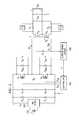
- FIG. 1illustrated is a schematic diagram of an embodiment of a power converter (e.g., a resonant half-bridge dc-dc power converter) constructed according to the principles of the present invention.
- the power converterincludes first and second power switches Q 1 , Q 2 in series with a dc bus (at an input of the power converter) produced by a dc input voltage source 110 , represented in FIG. 1 by a battery, and filtered by an electromagnetic interference (“EMI”) filter 120 .
- EMIelectromagnetic interference
- First and second switch capacitors C Q1 , C Q2represent capacitances of the first and second power switches Q 1 , Q 2 , respectively, or alternatively, discrete capacitors optionally included in the power converter to retard voltage changes across the first and second power switches Q 1 , Q 2 .
- the EMI filter 120provides a substantially filtered dc bus voltage or input voltage V in to a magnetic device (e.g., an isolating transformer or transformer T 1 ). Typically, the dc input voltage source 110 would be produced by a bridge rectifier or by a power-factor correction stage. Although the EMI filter 120 illustrated in FIG.
- the transformer T 1coupled to the first and second power switches Q 1 , Q 2 , has a primary winding N p and secondary windings N s1 , N s2 with a turns ratio n:1:1 that is selected to provide an output voltage V out with consideration of the range of the input voltage V in and stress on the power train of the power converter.
- a resonant full-bridge dc-dc power convertermay be formed with two power switches substituted for the first and second divider capacitors C 4 , C 5 . Each of the added power switches in a full-bridge configuration would be switched substantially synchronously with a diagonally oriented power switch.
- the first and second power switches Q 1 , Q 2are controlled by a controller 140 that produces control signals (e.g., gate-drive signals D Q1 , D Q2 ) to control the first and second power switches Q 1 , Q 2 to conduct for particular intervals of time (i.e., for particular “on” times).
- control signalse.g., gate-drive signals D Q1 , D Q2
- the term “signal”is used herein to represent, without limitation, a physical voltage or current.
- the ac voltage appearing or present on the secondary windings N s1 , N s2 of the transformer T 1is rectified by first and second diodes D 1 , D 2 , and the dc component of the resulting waveform is coupled to the output through the low-pass output filter formed with output filter capacitor C out to produce the output voltage V out .
- a sensore.g., a current-sense circuit 130 senses a condition of the power converter such as a current level of the primary current I pri that flows through the primary winding N p of the transformer T 1 and provides a sensed signal (e.g., a sensed current I T ) for the controller 140 representative of a level of the primary current I pri , such as a peak or root-mean-square value of the primary current I pri .
- the current-sense circuit 130is coupled to a resonant circuit (see below) and is configured to provide a sensed signal (e.g., a sensed current I T ) representative of a current level or a power level of the power converter.
- the power converteris operated as a resonant half-bridge topology.
- the term “resonant”is employed herein to refer to a switch-mode topology employing a resonant tank circuit or resonant circuit formed principally by a resonant capacitor C 1 and a resonant inductor L res to produce a current waveform that is a portion of, but typically not a full, sinusoidal waveform.
- the resonant circuitis series-coupled to the transformer T 1 .
- the circuit node between the first and second divider capacitors C 4 , C 5substantially remains at a voltage approximately equal to half of the input voltage V in with respect to a primary ground, which is identified with the symbol “p.”
- the secondary groundis identified with the symbol “s.”
- the source of second power switch Q 2is coupled to the primary ground p.
- the resonant capacitor C 1 and the first and second divider capacitors C 4 , C 5are coupled together at common circuit node N 0 .
- the first and second divider capacitors C 4 , C 5are roughly equal in capacitance and the combination is larger in capacitance than that of the resonant capacitor C 1 .
- Such a structureprovides symmetry from an EMI perspective for high frequency currents fed back to the dc input voltage source 110 , and also provides a relatively unvarying voltage at the common circuit node N 0 .
- one or both of the resonant capacitor C 1 and the first divider capacitor C 4can be omitted from the power converter.
- First and second clamping diodes D U , D Lprovide a clamping mechanism to limit the voltage at the common node N 0 to be no greater than the input voltage V in , and no lower than the primary ground p.
- the resonant inductor L resincludes the leakage inductance of the transformer T 1 referenced to its primary winding.
- the power converteroperates as a “dc transformer” that produces an output voltage V out substantially proportional to the input voltage V in .
- the output-to-input voltage ratiois substantially fixed by the transformer T 1 turns ratio, and thus the power converter per se does not provide output voltage regulation.
- the output voltage V outis substantially independent of the switching frequency of the first and second power switches Q 1 , Q 2 over an operating range. Regulation of the output voltage V out can be provided by a pre-converter stage (not shown) that regulates the input voltage V in to the power converter illustrated in FIG. 1 .
- controle.g., modification, alteration, variation, etc.
- the dead time between fixed on times (or conduction periods) of the first and second power switches Q 1 , Q 2is varied to control the switching frequency. Neither the dead times between power switch conduction periods nor the on times of the first and second power switches Q 1 , Q 2 are required to be equal.
- the on times of the first and second power switches Q 1 , Q 2are substantially equal to the half period T half defined by the resonant inductor L res and the effective resonant capacitance is C eff .
- the dead timesmay be substantially equal.
- FIG. 2illustrated is a schematic diagram of an embodiment of a power converter (e.g., a resonant half-bridge dc-dc power converter) constructed according to the principles of the present invention.
- the power converter illustrated in FIG. 2is similar to that illustrated in FIG. 1 but now includes first and second impedances Z 1 , Z 2 coupled across (e.g., parallel-coupled to) the first and second diodes D 1 , D 2 , respectively.
- the first and second impedances Z 1 , Z 2may be formed with ceramic capacitors substantially tuned to a frequency of a damped oscillation of a voltage produced across the first and second diodes D 1 , D 2 when the diodes are back biased during a switching cycle of the power converter.
- the first and second impedances Z 1 , Z 2are configured to convert the damped oscillatory voltage produced across the first and second diodes D 1 , D 2 to a dc current supplied to the output voltage V out of the power converter as a further efficiency enhancing process.
- the first and second impedances Z 1 , Z 2may include a nonlinear circuit element such as a diode to enable conversion of the oscillatory voltage produced across the first and second diodes D 1 , D 2 to the dc current supplied to the output voltage V out of the power converter.
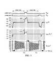
- FIG. 3illustrated is a graphical representation of an exemplary operation of a power converter (e.g., the power converter of FIG. 1 ) in accordance with the principles of the present invention.
- the first two waveforms(designated D Q1 and D Q2 ) illustrate the control signals (gate-drive signals) produced by the controller 140 for the first and second power switches Q 1 , Q 2 , respectively, in time (milliseconds (“ms”)).
- the third waveform(designated I pri ) illustrates the current (in milliamperes (“mA”) versus time in milliseconds) that flows through the primary winding of the transformer T 1 .
- the fourth waveform(designated I drain ) illustrates a drain current (in amperes (“A”) versus time in milliseconds) of the second power switch Q 2 .
- the fifth waveform(designated V ds — Q2 ) illustrates the drain-to-source voltage (in volts (“V”) versus time in milliseconds) of the second power switch Q 2 .
- FIG. 3illustrates dead times (designated “dead time”) between the on times (or conduction periods) of the first and second power switches Q 1 , Q 2 that are controlled by the controller 140 .
- FIG. 1dead times between the on times (or conduction periods) of the first and second power switches Q 1 , Q 2 that are controlled by the controller 140 .
- FIG. 3illustrates a pulse of current 310 that flows out the drain (designated I drain ) of the second power switch Q 2 to discharge an output capacitance thereof (e.g., the second switch capacitor C Q2 ).
- FIG. 3also illustrates that a portion 320 of the waveform of current that flows through the primary winding (designated I pri ) of the transformer T 1 is a portion of a sinusoidal waveform.
- the power trainis operated at a switching frequency that is a little lower, for example ten percent lower, than the resonant frequency f res of the resonant circuit.
- the on time T on of each of the first and second power switches Q 1 , Q 2corresponds to an on time that is equivalent to a frequency that is a little higher, for example three percent higher, than the resonant frequency of the resonant circuit.
- the on time T on for each of the first and second power switches Q 1 , Q 2is a little shorter or less than the half period T half of the resonant circuit, and together the first and second power switches Q 1 , Q 2 are on for a period of time that is a little shorter or less than twice the half period T half .
- the on times T on of the first and second power switches Q 1 , Q 2are not necessarily equal.
- the first and second power switches Q 1 , Q 2 and the first and second diodes D 1 , D 2are turned off prior to the time the current in the resonant circuit reaches zero, and the switching period is kept long enough (including delay times) to assure that, throughout the tolerance band of variations of power converter inductances and capacitances, the current through a diode on a primary side of the power converter will shift to an anti-parallel diode (or body diode) of the power switch that is about to be turned on prior to turning on the same or that the resonant current has decayed to approximately zero.
- the power converter illustrated in FIG. 1is operated at a fixed switching frequency.
- a drawback of a fixed switching frequencyis that switching losses remain substantially constant and relatively high at light loads.
- the efficiency of the conventionally designed power converteris generally satisfactory over much of the load range except for light loads.
- the current through the resonant circuit, transformer, and output diodesdecreases with load, thus decreasing conduction losses as the load is reduced.
- the circulating current in the resonant circuit as well as switching lossesbecome high compared to conduction losses.
- power conversion efficiency of a conventionally designed converteris generally poor at light loads.
- a variable dead time dependent on a sensed signale.g., a power converter parameter
- a sensed signale.g., a power converter parameter
- the currentmay be sensed on the primary side of the power converter by averaging a ripple voltage in a resonant circuit of the power converter.
- the sensed currentis indicative of a power level of the power converter.
- dead timeUnlike small variations in dead time, such as 100 or 200 nanoseconds (“ns”) variations in dead time employed in conventional designs, to enable zero-voltage switching of a power converter over a range of power converter operating conditions, a variation (e.g., a substantial variation) in dead time is employed herein to improve power conversion efficiency at light loads. Variations in dead time sufficient to provide, without limitation, a factor of ten or more reduction in switching frequency at light loads may be employed herein.
- dead times between on times (or conduction periods) of power switchesis varied, and the power switches in a resonant bridge power converter are operated with a constant (or substantially constant) on time.
- the on time of the power switchesmay be controlled (e.g., slightly modulated) to reduce or cancel a ripple voltage (e.g., a 120 hertz ripple voltage) of an input voltage source such as an upstream power converter (e.g., a power factor correction converter) to the power converter employing the power switches.
- a ripple voltagee.g., a 120 hertz ripple voltage
- an upstream power convertere.g., a power factor correction converter
- the dead timesmay be increased as the load is decreased as indicated by a decrease of a current level or power level of the power converter. This causes the switching frequency of the power converter to decrease at light loads, thereby reducing switching losses.
- the resonant bridge power convertercontinues to operate as a dc transformer. Therefore, increasing the dead time causes current through the resonant circuit to increase and sufficient power converter output power is automatically maintained to ensure adequate power transfer to maintain dc-transformer operation.
- the dead timesare advantageously increased for loads below a chosen load point so that power losses can be reduced at low load levels, and conduction- and switching-loss trade-offs can be made for the power converter.
- FIG. 4illustrated is a graphical representation of an exemplary power converter efficiency versus load according to the principles of the present invention.
- a first waveform 410demonstrates the efficiency for a conventional resonant bridge power converter and the second waveform 420 demonstrates an exemplary efficiency for a power converter (e.g., a resonant bridge power converter) constructed according to the principles of the present invention.
- the efficiency of a conventional resonant bridge power convertertypically exhibits a maximum at about 50 to 75 percent load.
- the second waveform 420if the dead times are kept relatively low from about 75 to 100 percent load, but is increased for loads below about 50 to 75 percent, the efficiency of the resonant bridge power converter according to the present invention remains relatively high down to small loads. It should be understood that the load point may be selected at a difference level and still fall within the broad scope of the present invention.
- FIG. 5illustrated is a schematic diagram of an embodiment of sensor (e.g., a current-sense circuit) 510 constructed according to the principles of the present invention.
- the current-sense circuit 510produces a sensed signal (e.g., a sensed current I T ) representative of a current in a power converter such as the resonant bridge power converter illustrated in FIG. 1 .
- the current-sense circuit 510illustrates the use of a one-shot 520 to produce a variable delay.
- the second divider capacitor C 5 and the resonant inductor L res from FIG. 1are illustrated herein.
- a typical way to use a one-shot 520is to connect a timing capacitor C T (e.g., 100 pico farads) between the input pin R T C T and local circuit ground (which is identified with the symbol “p”), and a timing resistor R T (e.g., one mega ohm) from the pin R T C T to a positive bias voltage source V CC .
- a timing capacitor C Te.g., 100 pico farads
- R Te.g., 100 pico farads
- R Te.g., one mega ohm
- Control of the dead timesis implemented by monitoring average ripple voltage at a resonant capacitor (such as the resonant capacitor C 1 of FIG. 1 ) and supplying the sensed current I T representative of a current in the resonant capacitor C 1 .
- the ripple voltageis coupled to the current-sense circuit 510 with high-voltage sense capacitor C sense .
- the voltageis clamped to local circuit ground p with clamp diode D 3 so that the sense capacitor C sense becomes charged to a value that represents the sensed current as a positive voltage.
- the first and second delay resistors R 1 , R 2set the maximum and minimum delays. Typically, the first delay resistor R 1 is less than one kilo ohm and the second delay resistor R 2 is greater than one mega ohm. Actual values may be determined by the switching frequency range desired.
- a positive voltageinjects the sensed current I T through the second delay resistor R 2 into the timing capacitor C T .
- the timing resistor R Talso injects a dc current into the timing capacitor C T slightly less than V CC /R T .
- the timing resistor R T coupled to the bias voltage source V CCcan be replaced with a current source providing a current slightly less than V CC /R T .
- a limiting diodee.g., Zener diode Z
- Zener diode Zcan be used to limit the sensed current I T to a maximum value, thereby limiting a maximum value of the load at which the dead time varies (i.e., limiting a modification of the dead time to a dead time limit).
- a current in the resonant circuit or in another circuit elementcan be sensed with a different current-sense circuit including a current-sense transformer and a resistor-diode network coupled to a secondary side of the current-sense transformer to produce the sensed current I T .
- a current-sense resistor coupled to an operational amplifiercan also be employed to sense the current in the resonant bridge power converter to produce the sensed current I T .
- the sensed current I Tis coupled to the R T C T timing pin of one-shot (“monostable multivibrator”) 520 such as a CD4528 one-shot (e.g., a MM74HC4538 produced by Fairchild Semiconductor, described in the Fairchild Semiconductor datasheet titled “MM74HC4538 Dual Retriggerable Monostable Multivibrator,” dated August 2000, which is incorporated herein by reference).
- the delay produced by one-shot 520is controlled by the timing capacitor C T and the charging current flowing thereto set by the timing resistor R T coupled to the bias voltage source V CC .
- a diode D Amay be included in the current-sense circuit 510 to add nonlinearity to the timing change produced by the sensed current.
- a lower limit for the switching frequencymay be employed by choice of values for the first and second delay resistors R 1 , R 2 and the timing resistor R T to prevent the switching frequency from decreasing into an audible range, such as a range of frequencies below 20 kilohertz (“kHz”).
- a substantial change in the switching frequencysuch as a factor of ten or more change in the switching frequency over a range of loads presented to the power converter, may be employed to improve power conversion efficiency at a low power level.
- a lower limit of the switching frequency of one or four kilohertzmay be employed to produce a substantial change in power conversion efficiency.
- a small varnished or potted transformer operated at a switching frequency of one or four kilohertzwill generally not produce an objectionable level of audible noise.
- a burst mode of operationmay also be employed at a very low load level to provide further improvement in power conversion efficiency.
- FIG. 6illustrated is a schematic diagram of an embodiment of a controller constructed according to the principles of the present invention.
- the controlleris responsive to a sensed signal (e.g., a sensed current I T ) to produce gate-drive signals D Q1 , D Q2 .
- a sensed signale.g., a sensed current I T
- Control of the dead timesis implemented using a one-shot as illustrated and described with respect to FIG. 5 .
- a first one-shot 620creates a fixed pulse length to control the gate-drive signals D Q1 , D Q2 whose lengths are slightly less than half of a resonant circuit period.
- the first one-shot 620is employed to produce a fixed delay using a conventional resistor-capacitor connection to a R T C T timing pin (not shown).
- the fixed delaymay be set equal to, less than, or greater than a half period of a resonant circuit. This fixed delay corresponds to the on time of the power switches. If the on time of the power switches is greater than a half period of a resonant circuit, an opposing diode will conduct current while the driven power switch is still on, which may cause a current shoot-through that can destroy the power converter. Thus, it is preferable under such circumstances that the fixed delay remains less than or equal to a resonant half-period.
- a second one-shot 640is responsive to the sensed current I T representative of the current in the resonant circuit, which is related to power converter load current, to adjust the dead-time length between the conduction periods of power switches such as the first and second power switches Q 1 , Q 2 of the power converter FIG. 1 .
- a current source 690produces the sensed current I T , which may be representative of the sensed current I T from the current-sense circuit 510 illustrated and described above with respect to FIG. 5 .
- a startup step voltage 605enables the controller to operate.
- the startup step voltage 605is coupled to an input of an AND gate 610 , the output of which produces the input for the first one-shot 620 to produce a fixed on time (e.g., 20 microseconds) for the first and second power switches Q 1 , Q 2 .
- the output of the first one-shot 620is inverted by an inverter 630 .
- the output of the inverter 630provides a clocked input voltage “clk” for a D-type (“delay”) flip-flop 650 .
- the output of the inverter 630also provides an input for the second one-shot 640 .
- the output of the second one-shot 640is inverted by an inverter 660 to provide a variable off-time delay for the first and second power switches Q 1 , Q 2 .
- the output of the second one-shot 640 and the Q and QN (i.e., the normal and the inverted) outputs of the D-type flip-flop 650are coupled to the inputs of AND gates 670 , 680 to provide the gate-drive signals D Q1 , D Q2 . Analogous to FIG.
- a timing capacitor C Tis coupled to the input pin R T C T and local circuit ground (which is identified with the symbol “p”) of the second one-shot 640 , and a timing resistor R T from the pin R T C T to a positive bias voltage source V CC of the second one-shot 640 .
- a power convertere.g., a resonant bridge power converter
- the power converterincludes first and second power switches coupled to an input of the power converter, and a sensor coupled to the power converter configured to provide a sensed signal representative of at least one of a current level and a power level of the power converter.
- the power converteralso includes a controller configured to increase a dead time between conduction periods of the first and second power switches when the sensed signal indicates a decrease of at least one of the current level and the power level of the power converter.
- a transformeris coupled to the first and second power switches, and a resonant circuit is series-coupled to a primary winding of the transformer.
- the sensoris configured to provide the sensed signal by monitoring an average ripple voltage of the resonant circuit.
- the resonant circuitmay include a resonant inductor and a resonant capacitor coupled to the primary winding of the transformer.
- the senormay include a sense capacitor, a clamp diode, and at least one delay resistor
- the controllermay include a timing resistor, a timing capacitor and a one-shot.
- the sensormay be configured to limit a value of the sensed signal, thereby limiting a modification of the dead times to a dead time limit.
- the sensormay also include a limiting diode configured to limit a value of the sensed signal.
- the controlleris configured to control the dead times to control a switching frequency of the first and second power switches.
- the controlleris also configured to control the conduction periods of the first and second power switches to be substantially constant.
- the controllermay be configured to control a conduction period of at least one of the first and second power switches to be substantially equal to (including slightly less than) a half period of a resonant circuit of the power converter.
- a diode and a parallel-coupled impedanceare coupled to a secondary winding of the transformer.
- the parallel-coupled impedancemay be configured to convert a damped oscillatory voltage produced across a diode to a dc current supplied to an output of the power converter.
- the present inventionprovides a method of operating a power converter.
- the methodincludes coupling first and second power switches to an input of the power converter, providing a sensed signal representative of at least one of a current level and a power level of the power converter, and controlling a dead time between conduction periods of the first and second power switches as a function of the sensed signal.
- the power convertermay include a transformer coupled to the first and second power switches and a resonant circuit in series with a primary winding of the transformer.
- the methodmay provide the sensed signal by monitoring an average ripple voltage of the resonant circuit.
Landscapes
- Engineering & Computer Science (AREA)
- Power Engineering (AREA)
- Dc-Dc Converters (AREA)
Abstract
Description
Ceff=C1·(C4+C5)/(C1+C4+C5).
The half period Thalfof the resonant circuit, which is the period during which a power switch is turned on, can be represented approximately by the equation:
Thalf=π·√{square root over (Lres·Ceff)}.
Claims (20)
Priority Applications (1)
| Application Number | Priority Date | Filing Date | Title |
|---|---|---|---|
| US12/642,448US8520420B2 (en) | 2009-12-18 | 2009-12-18 | Controller for modifying dead time between switches in a power converter |
Applications Claiming Priority (1)
| Application Number | Priority Date | Filing Date | Title |
|---|---|---|---|
| US12/642,448US8520420B2 (en) | 2009-12-18 | 2009-12-18 | Controller for modifying dead time between switches in a power converter |
Publications (2)
| Publication Number | Publication Date |
|---|---|
| US20110149607A1 US20110149607A1 (en) | 2011-06-23 |
| US8520420B2true US8520420B2 (en) | 2013-08-27 |
Family
ID=44150818
Family Applications (1)
| Application Number | Title | Priority Date | Filing Date |
|---|---|---|---|
| US12/642,448Expired - Fee RelatedUS8520420B2 (en) | 2009-12-18 | 2009-12-18 | Controller for modifying dead time between switches in a power converter |
Country Status (1)
| Country | Link |
|---|---|
| US (1) | US8520420B2 (en) |
Cited By (23)
| Publication number | Priority date | Publication date | Assignee | Title |
|---|---|---|---|---|
| US8976549B2 (en) | 2009-12-03 | 2015-03-10 | Power Systems Technologies, Ltd. | Startup circuit including first and second Schmitt triggers and power converter employing the same |
| US9077248B2 (en) | 2009-06-17 | 2015-07-07 | Power Systems Technologies Ltd | Start-up circuit for a power adapter |
| US9088216B2 (en) | 2009-01-19 | 2015-07-21 | Power Systems Technologies, Ltd. | Controller for a synchronous rectifier switch |
| US20150229200A1 (en)* | 2014-02-12 | 2015-08-13 | Palo Alto Research Center Incorporated | Dc/dc converter and method |
| US9190898B2 (en) | 2012-07-06 | 2015-11-17 | Power Systems Technologies, Ltd | Controller for a power converter and method of operating the same |
| US9197132B2 (en) | 2006-12-01 | 2015-11-24 | Flextronics International Usa, Inc. | Power converter with an adaptive controller and method of operating the same |
| US20150381059A1 (en)* | 2014-06-25 | 2015-12-31 | Siemens Aktiengesellschaft | Activation circuit of a resonance converter |
| US9240712B2 (en) | 2012-12-13 | 2016-01-19 | Power Systems Technologies Ltd. | Controller including a common current-sense device for power switches of a power converter |
| US9246391B2 (en) | 2010-01-22 | 2016-01-26 | Power Systems Technologies Ltd. | Controller for providing a corrected signal to a sensed peak current through a circuit element of a power converter |
| US9300206B2 (en) | 2013-11-15 | 2016-03-29 | Power Systems Technologies Ltd. | Method for estimating power of a power converter |
| US9553540B2 (en) | 2015-01-21 | 2017-01-24 | Ford Global Technologies, Llc | Power converter with pre-compensation for dead-time insertion |
| US9906167B2 (en) | 2015-01-21 | 2018-02-27 | Ford Global Technologies, Llc | Power converter with selective dead-time insertion |
| US10270364B2 (en) | 2015-01-21 | 2019-04-23 | Ford Global Technologies, Llc | Power converter with dead-time variation to disperse distortion |
| US10277115B2 (en) | 2016-04-15 | 2019-04-30 | Emerson Climate Technologies, Inc. | Filtering systems and methods for voltage control |
| US10284132B2 (en) | 2016-04-15 | 2019-05-07 | Emerson Climate Technologies, Inc. | Driver for high-frequency switching voltage converters |
| US10305373B2 (en) | 2016-04-15 | 2019-05-28 | Emerson Climate Technologies, Inc. | Input reference signal generation systems and methods |
| US10305363B1 (en)* | 2018-03-29 | 2019-05-28 | Semiconductor Components Industries, Llc | Current doubling DC-DC converter with efficient sleep mode |
| US10312798B2 (en) | 2016-04-15 | 2019-06-04 | Emerson Electric Co. | Power factor correction circuits and methods including partial power factor correction operation for boost and buck power converters |
| US10437317B2 (en) | 2016-04-15 | 2019-10-08 | Emerson Climate Technologies, Inc. | Microcontroller architecture for power factor correction converter |
| US10483858B2 (en)* | 2017-09-15 | 2019-11-19 | Abb Schweiz Ag | System and method for starting up a high density isolated DC-to-DC power converter |
| US10656026B2 (en) | 2016-04-15 | 2020-05-19 | Emerson Climate Technologies, Inc. | Temperature sensing circuit for transmitting data across isolation barrier |
| US10763740B2 (en) | 2016-04-15 | 2020-09-01 | Emerson Climate Technologies, Inc. | Switch off time control systems and methods |
| US20250070656A1 (en)* | 2023-08-22 | 2025-02-27 | Texas Instruments Incorporated | Hysteric control for resonant converters |
Families Citing this family (42)
| Publication number | Priority date | Publication date | Assignee | Title |
|---|---|---|---|---|
| US7280026B2 (en) | 2002-04-18 | 2007-10-09 | Coldwatt, Inc. | Extended E matrix integrated magnetics (MIM) core |
| EP1869758B1 (en)* | 2005-04-01 | 2012-10-10 | Nxp B.V. | Control of a resonant converter |
| US7675759B2 (en)* | 2006-12-01 | 2010-03-09 | Flextronics International Usa, Inc. | Power system with power converters having an adaptive controller |
| US7468649B2 (en) | 2007-03-14 | 2008-12-23 | Flextronics International Usa, Inc. | Isolated power converter |
| CN102217181B (en)* | 2008-11-14 | 2014-09-03 | 伟创力国际美国公司 | Driver for a synchronous rectifier and power converter employing the same |
| WO2010083511A1 (en) | 2009-01-19 | 2010-07-22 | Flextronics International Usa, Inc. | Controller for a power converter |
| US9019061B2 (en) | 2009-03-31 | 2015-04-28 | Power Systems Technologies, Ltd. | Magnetic device formed with U-shaped core pieces and power converter employing the same |
| US8643222B2 (en)* | 2009-06-17 | 2014-02-04 | Power Systems Technologies Ltd | Power adapter employing a power reducer |
| US8514593B2 (en) | 2009-06-17 | 2013-08-20 | Power Systems Technologies, Ltd. | Power converter employing a variable switching frequency and a magnetic device with a non-uniform gap |
| US8638578B2 (en)* | 2009-08-14 | 2014-01-28 | Power System Technologies, Ltd. | Power converter including a charge pump employable in a power adapter |
| US8520420B2 (en)* | 2009-12-18 | 2013-08-27 | Power Systems Technologies, Ltd. | Controller for modifying dead time between switches in a power converter |
| US8787043B2 (en) | 2010-01-22 | 2014-07-22 | Power Systems Technologies, Ltd. | Controller for a power converter and method of operating the same |
| CN102870320B (en) | 2010-03-17 | 2016-11-02 | 电力系统技术有限公司 | The control system of power converter and operational approach thereof |
| US8792257B2 (en) | 2011-03-25 | 2014-07-29 | Power Systems Technologies, Ltd. | Power converter with reduced power dissipation |
| DE102011078579A1 (en)* | 2011-07-04 | 2013-01-10 | Robert Bosch Gmbh | Drive circuit and method for driving the input switching stage of a transformer circuit |
| US9143044B2 (en)* | 2011-09-13 | 2015-09-22 | Futurewei Technologies, Inc. | Apparatus and method for pulse width modulation control for switching power converters |
| US9419510B2 (en)* | 2011-10-17 | 2016-08-16 | Queen's University At Kingston | Ripple cancellation converter with high power factor |
| CN103105956B (en)* | 2011-11-11 | 2015-05-06 | 汉王科技股份有限公司 | Position indicating device and position indicating method |
| US8792256B2 (en) | 2012-01-27 | 2014-07-29 | Power Systems Technologies Ltd. | Controller for a switch and method of operating the same |
| DE102012007477B4 (en) | 2012-04-13 | 2024-02-22 | Tridonic Gmbh & Co Kg | Method for operating an LLC resonant converter for a lamp, converter and LED converter |
| TW201347383A (en)* | 2012-05-07 | 2013-11-16 | Skynet Electronic Co Ltd | LLC series resonant converter using current circulating circuit to achieve light load voltage regulation mechanism |
| US9099232B2 (en) | 2012-07-16 | 2015-08-04 | Power Systems Technologies Ltd. | Magnetic device and power converter employing the same |
| US9679695B2 (en)* | 2012-07-16 | 2017-06-13 | Qualcomm Incorporated | Tuning circuit and method for wireless power transfer systems |
| US9214264B2 (en) | 2012-07-16 | 2015-12-15 | Power Systems Technologies, Ltd. | Magnetic device and power converter employing the same |
| US9106130B2 (en) | 2012-07-16 | 2015-08-11 | Power Systems Technologies, Inc. | Magnetic device and power converter employing the same |
| US9379629B2 (en) | 2012-07-16 | 2016-06-28 | Power Systems Technologies, Ltd. | Magnetic device and power converter employing the same |
| US9871459B2 (en)* | 2013-05-30 | 2018-01-16 | Enphase Energy, Inc. | Method and apparatus for deriving current for control in a resonant power converter |
| GB2517761A (en)* | 2013-08-30 | 2015-03-04 | Control Tech Ltd | Dead-time selection in power converters |
| US20150098254A1 (en)* | 2013-10-09 | 2015-04-09 | Power Systems Technologies Ltd. | Controller for use with a power converter and method of operating the same |
| US9490704B2 (en)* | 2014-02-12 | 2016-11-08 | Delta Electronics, Inc. | System and methods for controlling secondary side switches in resonant power converters |
| FR3020523B1 (en)* | 2014-04-29 | 2016-05-06 | Valeo Systemes De Controle Moteur | ELECTRICAL POWER SUPPLY AND METHOD FOR CONTROLLING AN ELECTRIC POWER SUPPLY |
| TWI596880B (en)* | 2014-06-30 | 2017-08-21 | 光寶科技股份有限公司 | A quasi-resonant half-bridge converter and control method |
| JP6196954B2 (en)* | 2014-09-22 | 2017-09-13 | コーセル株式会社 | Switching power supply |
| CN104682745B (en)* | 2015-03-05 | 2017-07-28 | 成都芯源系统有限公司 | Isolated voltage conversion circuit, control circuit and control method thereof |
| EP3068027B1 (en)* | 2015-03-13 | 2018-06-13 | Nxp B.V. | A controller for a resonant converter |
| MY191640A (en)* | 2016-06-02 | 2022-07-05 | Nissan Motor | Power conversion device |
| US20180191271A1 (en)* | 2016-12-30 | 2018-07-05 | Texas Instruments Incorporated | Detecting resonance frequency in llc switching converters from primary side |
| US11043902B2 (en)* | 2018-03-09 | 2021-06-22 | Eugene F. Krzywinski | Bidirectional DC DC converter interface to a DC AC inverter and energy storage |
| US10658937B1 (en)* | 2019-03-12 | 2020-05-19 | Semiconductor Components Industries, Llc | Controller for closed loop control of a DCX converter and method therefor |
| US11005363B1 (en)* | 2020-04-08 | 2021-05-11 | Delta Electronics (Thailand) Public Company Limited | Resonant power converter and current synthesizing method therefor |
| US12046997B2 (en) | 2020-07-13 | 2024-07-23 | Delta Electronics, Inc. | Isolated resonant converter and control method thereof |
| US11955897B2 (en)* | 2021-02-04 | 2024-04-09 | Texas Instruments Incorporated | Resonant DC-DC converter with average half cycle control |
Citations (329)
| Publication number | Priority date | Publication date | Assignee | Title |
|---|---|---|---|---|
| US1376978A (en) | 1917-11-24 | 1921-05-03 | Cutler Hammer Mfg Co | Regulator for alternating currents |
| US2473662A (en) | 1944-08-02 | 1949-06-21 | Lorain Prod Corp | Rectifying arrangement |
| US3007060A (en) | 1959-03-23 | 1961-10-31 | Gen Dynamics Corp | Circuitry for independently delaying the leading and trailing edges of an input pulse |
| US3346798A (en) | 1963-08-08 | 1967-10-10 | Gen Electric | Regulator for inverter |
| US3358210A (en) | 1964-06-25 | 1967-12-12 | Gen Electric | Voltage regulator |
| US3433998A (en) | 1965-04-24 | 1969-03-18 | Philips Corp | Circuit arrangement for frame correction |
| US3484562A (en) | 1966-09-21 | 1969-12-16 | Nortronics Co | Magnetic transducer with clamped body sections to hold core pieces |
| US3553620A (en) | 1967-09-14 | 1971-01-05 | Ibm | Combined transformer and indicator device |
| US3602795A (en) | 1969-10-16 | 1971-08-31 | Ibm | Transformerless power supply |
| US3622868A (en) | 1970-02-06 | 1971-11-23 | Joachim H Todt | Regulating power transformer with magnetic shunt |
| US3681679A (en) | 1971-05-07 | 1972-08-01 | Kheemoy Chung | Constant voltage transformer three-phase ferro resonant |
| US3708742A (en) | 1971-06-30 | 1973-01-02 | Ibm | High dc to low dc voltage converter |
| US3708744A (en) | 1971-08-18 | 1973-01-02 | Westinghouse Electric Corp | Regulating and filtering transformer |
| US4019122A (en) | 1974-08-14 | 1977-04-19 | Telcon-Magnetic Cores Limited | Stabilized power supplies |
| US4075547A (en) | 1975-07-23 | 1978-02-21 | Frequency Technology, Inc. | Voltage regulating transformer |
| US4202031A (en) | 1978-11-01 | 1980-05-06 | General Electric Company | Static inverter employing an assymetrically energized inductor |
| US4257087A (en) | 1979-04-02 | 1981-03-17 | California Institute Of Technology | DC-to-DC switching converter with zero input and output current ripple and integrated magnetics circuits |
| US4274071A (en) | 1979-11-16 | 1981-06-16 | Bell Telephone Laboratories, Incorporated | Three-phase ferroresonant transformer structure embodied in one unitary transformer construction |
| US4327348A (en) | 1977-05-20 | 1982-04-27 | Tdk Electronics Co., Ltd. | Variable leakage transformer |
| US4471423A (en) | 1982-02-17 | 1984-09-11 | Hase A M | Multi-voltage DC output with single reactor voltage control |
| US4499481A (en) | 1983-09-14 | 1985-02-12 | The United States Of America As Represented By The Secretary Of The Navy | Heterojunction Schottky gate MESFET with lower channel ridge barrier |
| US4570174A (en) | 1981-08-21 | 1986-02-11 | The United States Of America As Represented By The Secretary Of The Army | Vertical MESFET with air spaced gate electrode |
| US4577268A (en) | 1982-12-20 | 1986-03-18 | Rca Corporation | Switching dc-to-dc converters |
| US4581691A (en) | 1984-04-23 | 1986-04-08 | At&T Bell Laboratories | Balanced constant current sensing circuit inherently immune to longitudinal currents |
| US4613841A (en) | 1983-11-30 | 1986-09-23 | General Electric Company | Integrated transformer and inductor |
| US4636823A (en) | 1984-06-05 | 1987-01-13 | California Institute Of Technology | Vertical Schottky barrier gate field-effect transistor in GaAs/GaAlAs |
| US4660136A (en) | 1985-01-24 | 1987-04-21 | Honeywell Inc. | Single regulation power supply with load compensation of an auxiliary voltage output |
| US4770668A (en) | 1988-01-19 | 1988-09-13 | National Starch And Chemical Corporation | Ethylene urea compositions useful as permanent press promoting chemicals |
| US4770667A (en) | 1982-12-07 | 1988-09-13 | Board Of Regents, U T Systems | Use of substituted 2-(2'-hydroxyaryl)-2H-benzotriazolesulfonates as photostabilizing agents for natural and synthetic fibres |
| US4785387A (en) | 1986-04-28 | 1988-11-15 | Virginia Tech Intellectual Properties, Inc. | Resonant converters with secondary-side resonance |
| US4799138A (en) | 1986-09-26 | 1989-01-17 | Kabelmetal Electro Gesellschaft Mit Beschrankter Haftung | Circuit for producing an alternating voltage |
| US4803609A (en) | 1985-10-31 | 1989-02-07 | International Business Machines Corporation | D. C. to D. C. converter |
| US4823249A (en) | 1987-04-27 | 1989-04-18 | American Telephone And Telegraph Company At&T Bell Laboratories | High-frequency resonant power converter |
| US4837496A (en) | 1988-03-28 | 1989-06-06 | Linear Technology Corporation | Low voltage current source/start-up circuit |
| US4866367A (en) | 1988-04-11 | 1989-09-12 | Virginia Tech Intellectual Properties, Inc. | Multi-loop control for quasi-resonant converters |
| US4887061A (en) | 1988-01-18 | 1989-12-12 | Tdk Corporation | Transformer for a flyback type converter |
| US4899271A (en) | 1987-07-22 | 1990-02-06 | Scanpower | Power supply circuit |
| US4903089A (en) | 1988-02-02 | 1990-02-20 | Massachusetts Institute Of Technology | Vertical transistor device fabricated with semiconductor regrowth |
| US4922400A (en) | 1989-08-03 | 1990-05-01 | Sundstrand Corporation | Neutral forming circuit |
| US4962354A (en) | 1989-07-25 | 1990-10-09 | Superconductivity, Inc. | Superconductive voltage stabilizer |
| US4964028A (en) | 1989-10-26 | 1990-10-16 | Plessey Electronic Systems Corp. | Current limited quasi-resonant voltage converting power supply |
| US4999759A (en) | 1989-09-27 | 1991-03-12 | Cavagnolo Gian P | Multiple output switching power supply having one controlled output voltage and load compensation |
| US5003277A (en) | 1988-08-15 | 1991-03-26 | Mitsubishi Denki Kabushiki Kaisha | Phase-shifting transformer with a six-phase core |
| US5014178A (en) | 1990-05-14 | 1991-05-07 | Power Integrations, Inc. | Self powering technique for integrated switched mode power supply |
| US5027264A (en) | 1989-09-29 | 1991-06-25 | Wisconsin Alumni Research Foundation | Power conversion apparatus for DC/DC conversion using dual active bridges |
| US5068756A (en) | 1989-02-16 | 1991-11-26 | Texas Instruments Incorporated | Integrated circuit composed of group III-V compound field effect and bipolar semiconductors |
| US5106778A (en) | 1988-02-02 | 1992-04-21 | Massachusetts Institute Of Technology | Vertical transistor device fabricated with semiconductor regrowth |
| US5126714A (en) | 1990-12-20 | 1992-06-30 | The United States Of America As Represented By The Secretary Of The Navy | Integrated circuit transformer |
| US5132888A (en) | 1991-01-07 | 1992-07-21 | Unisys Corporation | Interleaved bridge converter |
| US5134771A (en) | 1991-07-05 | 1992-08-04 | General Electric Company | Method for manufacturing and amorphous metal core for a transformer that includes steps for reducing core loss |
| US5172309A (en) | 1991-08-07 | 1992-12-15 | General Electric Company | Auxiliary quasi-resonant dc link converter |
| US5177460A (en) | 1990-01-04 | 1993-01-05 | Dhyanchand P John | Summing transformer for star-delta inverter having a single secondary winding for each group of primary windings |
| US5182535A (en) | 1989-12-19 | 1993-01-26 | Dhyanchand P John | Summing transformer core for star-delta inverter having a separate secondary winding for each primary winding |
| US5204809A (en) | 1992-04-03 | 1993-04-20 | International Business Machines Corporation | H-driver DC-to-DC converter utilizing mutual inductance |
| US5206621A (en) | 1990-07-02 | 1993-04-27 | General Electric Company | Barrel-wound conductive film transformer |
| US5208739A (en) | 1992-01-07 | 1993-05-04 | Powercube Corporation | Integrated magnetic power converter |
| US5223449A (en) | 1989-02-16 | 1993-06-29 | Morris Francis J | Method of making an integrated circuit composed of group III-V compound field effect and bipolar semiconductors |
| US5225971A (en) | 1992-01-08 | 1993-07-06 | International Business Machines Corporation | Three coil bridge transformer |
| US5231037A (en) | 1992-04-30 | 1993-07-27 | Texas Instruments Incorporated | Method of making a power VFET device using a p+ carbon doped gate layer |
| US5244829A (en) | 1992-07-09 | 1993-09-14 | Texas Instruments Incorporated | Organometallic vapor-phase epitaxy process using (CH3)3 As and CCl4 for improving stability of carbon-doped GaAs |
| US5262930A (en) | 1992-06-12 | 1993-11-16 | The Center For Innovative Technology | Zero-voltage transition PWM converters |
| US5282126A (en) | 1991-08-01 | 1994-01-25 | U.S. Philips Corporation | Start circuit for a switched mode power supply |
| US5285396A (en) | 1991-01-11 | 1994-02-08 | Tadamasa Aoyama | Device for evaluating race horse performance based on temperature |
| US5291382A (en) | 1991-04-10 | 1994-03-01 | Lambda Electronics Inc. | Pulse width modulated DC/DC converter with reduced ripple current coponent stress and zero voltage switching capability |
| US5303138A (en) | 1993-04-29 | 1994-04-12 | At&T Bell Laboratories | Low loss synchronous rectifier for application to clamped-mode power converters |
| US5305191A (en) | 1992-04-20 | 1994-04-19 | At&T Bell Laboratories | Drive circuit for zero-voltage switching power converter with controlled power switch turn-on |
| US5335163A (en) | 1990-11-14 | 1994-08-02 | Scanpower | Power supply circuit with integrated magnetic components |
| US5336985A (en) | 1992-11-09 | 1994-08-09 | Compaq Computer Corp. | Tapped inductor slave regulating circuit |
| US5342795A (en) | 1992-04-30 | 1994-08-30 | Texas Instruments Incorporated | Method of fabricating power VFET gate-refill |
| US5343140A (en) | 1992-12-02 | 1994-08-30 | Motorola, Inc. | Zero-voltage-switching quasi-resonant converters with multi-resonant bipolar switch |
| US5353001A (en) | 1991-01-24 | 1994-10-04 | Burr-Brown Corporation | Hybrid integrated circuit planar transformer |
| US5369042A (en) | 1993-03-05 | 1994-11-29 | Texas Instruments Incorporated | Enhanced performance bipolar transistor process |
| US5374887A (en) | 1993-11-12 | 1994-12-20 | Northern Telecom Limited | Inrush current limiting circuit |
| US5399968A (en) | 1992-01-31 | 1995-03-21 | Northrop Grumman Corporation | Eddy current probe having body of high permeability supporting drive coil and plural sensors |
| EP0665634A1 (en) | 1994-01-31 | 1995-08-02 | Siemens Aktiengesellschaft | Circuit arrangement with a field effect transistor |
| US5459652A (en) | 1994-01-28 | 1995-10-17 | Compaq Computer Corp. | Boot strap circuit for power up control of power supplies |
| US5468661A (en) | 1993-06-17 | 1995-11-21 | Texas Instruments Incorporated | Method of making power VFET device |
| US5477175A (en) | 1993-10-25 | 1995-12-19 | Motorola | Off-line bootstrap startup circuit |
| US5508903A (en) | 1995-04-21 | 1996-04-16 | Alexndrov; Felix | Interleaved DC to DC flyback converters with reduced current and voltage stresses |
| US5523673A (en) | 1994-03-04 | 1996-06-04 | Marelco Power Systems, Inc. | Electrically controllable inductor |
| US5539630A (en)* | 1993-11-15 | 1996-07-23 | California Institute Of Technology | Soft-switching converter DC-to-DC isolated with voltage bidirectional switches on the secondary side of an isolation transformer |
| US5555494A (en) | 1993-09-13 | 1996-09-10 | Morris; George Q. | Magnetically integrated full wave DC to DC converter |
| US5554561A (en) | 1993-04-30 | 1996-09-10 | Texas Instruments Incorporated | Epitaxial overgrowth method |
| US5610085A (en) | 1993-11-29 | 1997-03-11 | Texas Instruments Incorporated | Method of making a vertical FET using epitaxial overgrowth |
| US5624860A (en) | 1993-04-30 | 1997-04-29 | Texas Instruments Incorporated | Vertical field effect transistor and method |
| US5663876A (en) | 1995-09-25 | 1997-09-02 | Lucent Technologies Inc. | Circuit and method for achieving zero ripple current in the output of a converter |
| US5700703A (en) | 1996-08-06 | 1997-12-23 | Motorola | Method of fabricating buried control elements in semiconductor devices |
| US5712189A (en) | 1993-04-30 | 1998-01-27 | Texas Instruments Incorporated | Epitaxial overgrowth method |
| US5719544A (en) | 1991-09-13 | 1998-02-17 | Vlt Corporation | Transformer with controlled interwinding coupling and controlled leakage inducances and circuit using such transformer |
| US5734564A (en) | 1996-07-26 | 1998-03-31 | Lucent Technologies Inc. | High-efficiency switching power converter |
| US5736842A (en) | 1996-07-11 | 1998-04-07 | Delta Electronics, Inc. | Technique for reducing rectifier reverse-recovery-related losses in high-voltage high power converters |
| US5742491A (en) | 1995-08-09 | 1998-04-21 | Lucent Technologies Inc. | Power converter adaptively driven |
| US5756375A (en) | 1995-06-14 | 1998-05-26 | Texas Instruments Incorporated | Semiconductor growth method with thickness control |
| US5760671A (en) | 1995-09-15 | 1998-06-02 | Celestica Inc. | Transformer with dual flux path |
| US5784266A (en) | 1996-06-14 | 1998-07-21 | Virginia Power Technologies, Inc | Single magnetic low loss high frequency converter |
| US5783984A (en) | 1995-06-16 | 1998-07-21 | Hughes Electronics | Method and means for combining a transformer and inductor on a single core structure |
| US5804943A (en) | 1995-05-12 | 1998-09-08 | Texas Instruments Incorporated | Resonant bilateral charging and discharging circuit |
| US5815383A (en) | 1995-06-15 | 1998-09-29 | Supertex, Inc. | High voltage start-up circuit and method therefor |
| US5815386A (en) | 1997-06-19 | 1998-09-29 | Factor One, Inc. | Snubber for zero current switched networks |
| US5864110A (en) | 1996-11-22 | 1999-01-26 | Sansha Electric Manufacturing Company, Limited | Power supply apparatus for plasma arc utilizing equipment |
| US5870299A (en) | 1997-05-28 | 1999-02-09 | Lucent Technologies Inc. | Method and apparatus for damping ringing in self-driven synchronous rectifiers |
| US5880942A (en) | 1997-03-17 | 1999-03-09 | Acer Peripherals Inc. | Power supply device with low power dissipation |
| US5886508A (en) | 1997-08-29 | 1999-03-23 | Computer Products, Inc. | Multiple output voltages from a cascaded buck converter topology |
| US5889660A (en) | 1997-03-06 | 1999-03-30 | Eaton Corporation | Isolated power supply for indicator light |
| US5900822A (en) | 1991-10-11 | 1999-05-04 | Helix Technology Corporation | Cryopump synchronous motor load monitor |
| US5907481A (en) | 1997-10-31 | 1999-05-25 | Telefonaktiebolaget Lm Ericsson | Double ended isolated D.C.--D.C. converter |
| US5909110A (en) | 1996-12-17 | 1999-06-01 | Texas Insturments Incorporated | Integrated voltage regulator circuit with vertical transistor |
| US5910665A (en) | 1995-12-29 | 1999-06-08 | Texas Instruments Incorporated | Low capacitance power VFET method and device |
| US5920475A (en) | 1995-05-04 | 1999-07-06 | Lucent Technologies Inc. | Circuit and method for controlling a synchronous rectifier converter |
| US5925088A (en) | 1995-01-30 | 1999-07-20 | Toyota Jidosha Kabushiki Kaisha | Air-fuel ratio detecting device and method |
| US5929665A (en)* | 1997-04-22 | 1999-07-27 | Kabushiki Kaisha Toshiba | Power converter with voltage drive switching device monitored by device parameters and electric parameters |
| US5933338A (en) | 1997-10-14 | 1999-08-03 | Peco Ii, Inc. | Dual coupled current doubler rectification circuit |
| US5940287A (en) | 1998-07-14 | 1999-08-17 | Lucent Technologies Inc. | Controller for a synchronous rectifier and power converter employing the same |
| US5946207A (en) | 1997-08-04 | 1999-08-31 | U.S. Philips Corporation | Power supply having a synchronous rectifier circuit for improved switching timing |
| US5956578A (en) | 1997-04-23 | 1999-09-21 | Motorola, Inc. | Method of fabricating vertical FET with Schottky diode |
| US5959850A (en) | 1997-11-18 | 1999-09-28 | Samsung Electro-Mechanics Co., Ltd. | Asymmetrical duty cycle flyback converter |
| US5977853A (en) | 1995-02-03 | 1999-11-02 | Murata Manufacturing Co., Ltd. | Choke coil for eliminating common mode noise and normal mode noise |
| US5999066A (en) | 1996-09-06 | 1999-12-07 | Toko Kabushiki Kaisha | Interface module for a sending section and a receiving section |
| US5999429A (en) | 1997-12-19 | 1999-12-07 | Dell Usa, L.P. | Bulk filter capacitor discharge in a switching power supply |
| US6003139A (en) | 1996-09-26 | 1999-12-14 | Compaq Computer Corporation | Computer system including power supply circuit with controlled output power |
| US6008519A (en) | 1996-12-16 | 1999-12-28 | Texas Instruments Incorporated | Vertical transistor and method |
| US6011703A (en) | 1997-07-30 | 2000-01-04 | Lucent Technologies Inc. | Self-synchronized gate drive for power converter employing self-driven synchronous rectifier and method of operation thereof |
| US6046664A (en) | 1998-03-05 | 2000-04-04 | Century Manufacturing Company | Welding power supply transformer apparatus and method |
| US6055166A (en) | 1998-11-16 | 2000-04-25 | Lucent Technologies Inc. | Low trickle current startup bias circuit and method of operation thereof |
| US6060943A (en) | 1998-04-14 | 2000-05-09 | Nmb (Usa) Inc. | Circuit simulating a diode |
| US6067237A (en) | 1997-08-21 | 2000-05-23 | Gec Alsthom Transport Sa | Reversible direct current power converter device capable of providing output voltages greater than the floating voltage of the secondary winding of the transformer |
| US6069798A (en) | 1999-01-14 | 2000-05-30 | Lucent Technologies Inc. | Asymmetrical power converter and method of operation thereof |
| US6069799A (en) | 1997-05-14 | 2000-05-30 | Lucent Technologies Inc. | Self-synchronized drive circuit for a synchronous rectifier in a clamped-mode power converter |
| US6078510A (en) | 1998-09-23 | 2000-06-20 | Stmicroelectronics S.R.L. | Wholly integrated switch-on control loop of a high voltage power transistor of a quasi resonant flyback converter |
| US6084792A (en) | 1998-08-21 | 2000-07-04 | Vpt, Inc. | Power converter with circuits for providing gate driving |
| US6094038A (en) | 1999-06-28 | 2000-07-25 | Semtech Corporation | Buck converter with inductive turn ratio optimization |
| US6097046A (en) | 1993-04-30 | 2000-08-01 | Texas Instruments Incorporated | Vertical field effect transistor and diode |
| US6125046A (en) | 1998-11-10 | 2000-09-26 | Fairfield Korea Semiconductor Ltd. | Switching power supply having a high efficiency starting circuit |
| US6144187A (en) | 1998-11-12 | 2000-11-07 | Fairchild Semiconductor Corporation | Power measurement for adaptive battery charger |
| US6147886A (en) | 1999-05-15 | 2000-11-14 | Technical Witts, Inc. | Dual opposed interleaved coupled inductor soft switching converters |
| US6156611A (en) | 1998-07-20 | 2000-12-05 | Motorola, Inc. | Method of fabricating vertical FET with sidewall gate electrode |
| US6160721A (en) | 1997-06-10 | 2000-12-12 | Lucent Technologies Inc. | Micromagnetic device for power processing applications and method of manufacture therefor |
| US6163466A (en) | 1999-09-16 | 2000-12-19 | Lucent Technologies, Inc. | Asymmetrical DC/DC converter having output current doubler |
| US6181231B1 (en) | 1998-04-06 | 2001-01-30 | Silicon Graphics, Inc. | Diamond-based transformers and power convertors |
| US6188586B1 (en) | 2000-04-21 | 2001-02-13 | Lucent Technologies Inc. | Asymmetrical half-bridge power converter having reduced input ripple and method of manufacturing the same |
| US6208535B1 (en) | 1994-10-31 | 2001-03-27 | Texas Instruments Incorporated | Resonant gate driver |
| US6215290B1 (en) | 1999-11-15 | 2001-04-10 | Semtech Corporation | Multi-phase and multi-module power supplies with balanced current between phases and modules |
| US6218891B1 (en) | 2000-07-28 | 2001-04-17 | Lucent Technologies Inc. | Integrated circuit including a driver for a metal-semiconductor field-effect transistor |
| US6229197B1 (en) | 1993-04-30 | 2001-05-08 | Texas Instruments Incorporated | Epitaxial overgrowth method and devices |
| US6262564B1 (en) | 2000-11-10 | 2001-07-17 | Lucent Technologies Inc. | Driver for a controllable switch in a power converter |
| US6288501B1 (en) | 1999-05-26 | 2001-09-11 | Matsushita Electric Works, Ltd. | Ballast for a discharge lamp |
| US6288920B1 (en) | 1998-10-21 | 2001-09-11 | Mark E. Jacobs | Drive compensation circuit for synchronous rectifier and method of operating the same |
| US6295217B1 (en) | 1999-03-26 | 2001-09-25 | Sarnoff Corporation | Low power dissipation power supply and controller |
| JP3215911B2 (en) | 1996-11-01 | 2001-10-09 | 株式会社呉竹精昇堂 | Multi-color ink for Japanese paper written with a brush |
| US6304460B1 (en) | 2000-05-05 | 2001-10-16 | Slobodan Cuk | Switching DC-to-DC converter utilizing a soft switching technique |
| US6309918B1 (en) | 1998-09-21 | 2001-10-30 | Motorola, Inc. | Manufacturable GaAs VFET process |
| US6317021B1 (en) | 1998-05-18 | 2001-11-13 | Nmb (Usa) Inc. | Variable inductor |
| US6317337B1 (en) | 1998-11-10 | 2001-11-13 | Sony Corporation | Switching power supply circuit |
| US6320490B1 (en) | 1999-08-13 | 2001-11-20 | Space Systems/Loral, Inc. | Integrated planar transformer and inductor assembly |
| US6323090B1 (en) | 1999-06-09 | 2001-11-27 | Ixys Corporation | Semiconductor device with trenched substrate and method |
| US6325035B1 (en) | 1999-09-30 | 2001-12-04 | Caterpillar Inc. | Method and apparatus for starting an engine using capacitor supplied voltage |
| US6345364B1 (en) | 1998-04-11 | 2002-02-05 | Samsung Electronics Co., Ltd. | Power supply of display apparatus with universal serial bus device |
| US6344986B1 (en) | 2000-06-15 | 2002-02-05 | Astec International Limited | Topology and control method for power factor correction |
| US6348848B1 (en) | 2000-05-04 | 2002-02-19 | Edward Herbert | Transformer having fractional turn windings |
| US6351396B1 (en) | 2000-03-04 | 2002-02-26 | Mark Elliott Jacobs | Method and apparatus for dynamically altering operation of a converter device to improve conversion efficiency |
| US6356462B1 (en) | 2000-08-31 | 2002-03-12 | Delta Electronics, Inc. | Soft-switched full-bridge converters |
| US6362986B1 (en) | 2001-03-22 | 2002-03-26 | Volterra, Inc. | Voltage converter with coupled inductive windings, and associated methods |
| US6373734B1 (en) | 2000-09-15 | 2002-04-16 | Artesyn Technologies, Inc. | Power factor correction control circuit and power supply including same |
| US6373727B1 (en) | 2000-03-10 | 2002-04-16 | Telefonaktiebolaget Lm Ericsson (Publ) | Synchronous rectification in a flyback converter |
| US6380836B2 (en) | 1999-03-11 | 2002-04-30 | Murata Manufacturing Co., Ltd. | Coil device and switching power supply apparatus using the same |
| US6388898B1 (en) | 2001-01-22 | 2002-05-14 | Delta Electronics, Inc. | Dc/dc power processor with distributed rectifier stage |
| US20020057080A1 (en) | 2000-06-02 | 2002-05-16 | Iwatt | Optimized digital regulation of switching power supply |
| US6400579B2 (en) | 2000-03-24 | 2002-06-04 | Slobodan Cuk | Lossless switching DC to DC converter with DC transformer |
| US6414578B1 (en) | 2000-12-18 | 2002-07-02 | Ascom Energy Systems Ag | Method and apparatus for transmitting a signal through a power magnetic structure |
| US6438009B2 (en) | 2000-03-24 | 2002-08-20 | Telefonaktiebolaget Lm Ericsson (Publ) | Reducing voltage transients across a MOSFET in a synchronous rectifier in a DC/DC converter |
| US20020114172A1 (en) | 2001-02-19 | 2002-08-22 | Rockwell Scientific Company, Llc | Converter circuit and method with auxiliary supply voltage |
| US6462965B1 (en) | 2000-09-06 | 2002-10-08 | Densei-Lambda Kabushiki Kaisha | Switching power supply |
| US6466461B2 (en) | 2001-02-09 | 2002-10-15 | Netpower Technologies, Inc. | Method and circuit for reducing voltage level variation in a bias voltage in a power converter |
| US6469564B1 (en) | 1998-04-14 | 2002-10-22 | Minebea Co., Ltd. | Circuit simulating a diode |
| US6483724B1 (en) | 2002-02-15 | 2002-11-19 | Valere Power, Inc. | DC/DC ZVS full bridge converter power supply method and apparatus |
| US6489754B2 (en) | 2000-11-01 | 2002-12-03 | Koninklijke Philips Electronics N.V. | Switched mode power supply having a boost converter operatively combined with a flyback converter |
| US6498367B1 (en) | 1999-04-01 | 2002-12-24 | Apd Semiconductor, Inc. | Discrete integrated circuit rectifier device |
| US6501193B1 (en) | 2001-09-07 | 2002-12-31 | Power-One, Inc. | Power converter having regulated dual outputs |
| US6504321B2 (en) | 2001-02-06 | 2003-01-07 | Koninklijke Philips Electronics N.V. | Universal hardware/software feedback control for high-frequency signals |
| US6512352B2 (en) | 2001-06-07 | 2003-01-28 | Koninklijke Philips Electronics N.V. | Active clamp step-down converter with power switch voltage clamping function |
| US20030026115A1 (en) | 2000-04-21 | 2003-02-06 | Takahiro Miyazaki | Switching-type DC-DC converter |
| US6525603B1 (en) | 2001-01-05 | 2003-02-25 | Remec, Inc. | Feedforward amplifier linearization adapting off modulation |
| US6539299B2 (en) | 2000-02-18 | 2003-03-25 | Optimum Power Technology | Apparatus and method for calibrating an engine management system |
| US6545453B2 (en) | 2001-04-03 | 2003-04-08 | Abb Inc. | Systems and methods for providing voltage regulation externally to a power transformer |
| US6549436B1 (en) | 2002-02-21 | 2003-04-15 | Innovative Technology Licensing Llc | Integrated magnetic converter circuit and method with improved filtering |
| US6548992B1 (en) | 2001-10-18 | 2003-04-15 | Innoveta Technologies, Inc. | Integrated power supply protection circuit |
| US6552917B1 (en) | 2001-11-05 | 2003-04-22 | Koninklijke Philips Electronics N.V. | System and method for regulating multiple outputs in a DC-DC converter |
| US6563725B2 (en) | 2001-10-03 | 2003-05-13 | Bruce W. Carsten | Apparatus and method for control and driving BJT used as synchronous rectifier |
| US6570268B1 (en) | 2000-11-20 | 2003-05-27 | Artesyn Technologies, Inc. | Synchronous rectifier drive circuit and power supply including same |
| US6580627B2 (en)* | 2001-01-29 | 2003-06-17 | International Rectifier Corporation | Voltage sensing with high and low side signals for deadtime compensation and shutdown for short circuit protection |
| US6597592B2 (en) | 2001-10-03 | 2003-07-22 | Bruce W. Carsten | Apparatus and method for turning off BJT used as controlled rectifier |
| US6608768B2 (en) | 2001-08-07 | 2003-08-19 | Salcomp Oy | Use of a rectified image voltage for controlling the switch on the primary side of a switched-mode power supply |
| US6611132B2 (en) | 2001-03-07 | 2003-08-26 | Fujitsu Limited | DC-DC converter, power supply circuit, method for controlling DC-DC converter, and method for controlling power supply circuit |
| US6614206B1 (en) | 2002-05-23 | 2003-09-02 | Palm, Inc. | Universal USB charging accessory |
| US20030197585A1 (en) | 2002-04-18 | 2003-10-23 | Innovative Technology Licensing, Llc | Core structure |
| US20030198067A1 (en) | 2002-04-18 | 2003-10-23 | Innovative Technology Licensing, Llc | Core structure and interleaved DC-DC converter topology |
| US6654259B2 (en) | 2000-12-22 | 2003-11-25 | Sony Corporation | Resonance type switching power supply unit |
| US6661276B1 (en) | 2002-07-29 | 2003-12-09 | Lovoltech Inc. | MOSFET driver matching circuit for an enhancement mode JFET |
| US6668296B1 (en) | 2000-06-30 | 2003-12-23 | Hewlett-Packard Development Company, L.P. | Powering a notebook across a USB interface |
| US6674658B2 (en) | 2001-02-09 | 2004-01-06 | Netpower Technologies, Inc. | Power converter including circuits for improved operational control of synchronous rectifiers therein |
| US6683797B2 (en) | 2002-01-24 | 2004-01-27 | Tdk Corporation | Multi-stage DC—DC converter |
| US20040017689A1 (en) | 2002-07-25 | 2004-01-29 | General Electric Company | Cross current control for power converter systems and integrated magnetic choke assembly |
| US6687137B1 (en) | 2000-05-10 | 2004-02-03 | Sony Corporation | Resonant switching power supply circuit with voltage doubler output |
| US20040034555A1 (en) | 2002-03-18 | 2004-02-19 | Dismukes John P. | Hierarchical methodology for productivity measurement and improvement of complex production systems |
| US6696910B2 (en) | 2001-07-12 | 2004-02-24 | Custom One Design, Inc. | Planar inductors and method of manufacturing thereof |
| US6731486B2 (en) | 2001-12-19 | 2004-05-04 | Fairchild Semiconductor Corporation | Output-powered over-voltage protection circuit |
| US6741099B1 (en) | 2003-01-31 | 2004-05-25 | Power-One Limited | Transistor driver circuit |
| US6753723B2 (en) | 2002-04-03 | 2004-06-22 | International Rectifier Corporation | Synchronous buck converter with improved transient performance |
| US6765810B2 (en) | 2002-08-02 | 2004-07-20 | Artesyn Technologies, Inc. | Full-wave coupled inductor power converter having synchronous rectifiers and two input switches that are simultaneously off for a time period of each switching cycle |
| US20040148047A1 (en) | 2001-12-18 | 2004-07-29 | Dismukes John P | Hierarchical methodology for productivity measurement and improvement of productions systems |
| US20040156220A1 (en) | 2002-11-26 | 2004-08-12 | Lg Electronics Inc. | Power supply |
| US6784644B2 (en) | 2001-02-22 | 2004-08-31 | Virginia Tech Intellectual Properties, Inc. | Multiphase clamp coupled-buck converter and magnetic integration |
| US6804125B2 (en) | 2001-02-01 | 2004-10-12 | Di/Dt Inc. | Isolated drive circuitry used in switch-mode power converters |
| US20040200631A1 (en) | 2003-04-10 | 2004-10-14 | Lei Chen | Cable and connection module for a universal serial bus interface |
| US6813170B2 (en) | 2002-08-19 | 2004-11-02 | Semtech Corporation | Multiple output power supply having soft start protection for load over-current or short circuit conditions |
| US20040217794A1 (en) | 2003-04-30 | 2004-11-04 | Mark Strysko | Propagation delay adjustment circuit |
| US6831847B2 (en) | 2000-11-20 | 2004-12-14 | Artesyn Technologies, Inc. | Synchronous rectifier drive circuit and power supply including same |
| US20050024179A1 (en) | 2002-04-18 | 2005-02-03 | Rockwell Scientific Licensing, Llc | Extended E matrix integrated magnetics (MIM) core |
| US6856149B2 (en) | 2003-06-19 | 2005-02-15 | Niko Semiconductor Co., Ltd. | Current detecting circuit AC/DC flyback switching power supply |
| US6862194B2 (en) | 2003-06-18 | 2005-03-01 | System General Corp. | Flyback power converter having a constant voltage and a constant current output under primary-side PWM control |
| US6867678B2 (en) | 2003-01-28 | 2005-03-15 | Entrust Power Co., Ltd. | Transformer structure |
| US6867986B2 (en) | 2003-02-03 | 2005-03-15 | Smk Corporation | Constant current output control method and constant current output control device for switching power supply circuit |
| US6882548B1 (en) | 2003-02-24 | 2005-04-19 | Tyco Electronics Power Systems, Inc. | Auxiliary active clamp circuit, a method of clamping a voltage of a rectifier switch and a power converter employing the circuit or method |
| US6906934B2 (en) | 2003-09-04 | 2005-06-14 | System General Corp. | Integrated start-up circuit with reduced power consumption |
| US6943553B2 (en) | 2002-08-23 | 2005-09-13 | Forschungszentrum Julich Gmbh | Method and apparatus for rapid tomographic measurements of the electrical conductivity distribution of a sample |
| US6944033B1 (en) | 2002-11-08 | 2005-09-13 | Va Tech Intellectual Properties | Multi-phase interleaving isolated DC/DC converter |
| US20050245658A1 (en) | 2004-04-30 | 2005-11-03 | Rockwell Scientific Licensing Llc | Synthesis of magnetic, dielectric or phosphorescent NANO composites |
| US6977824B1 (en) | 2004-08-09 | 2005-12-20 | System General Corp. | Control circuit for controlling output current at the primary side of a power converter |
| US20050281058A1 (en) | 2004-06-21 | 2005-12-22 | Issa Batarseh | Dynamic optimization of efficiency using dead time and FET drive control |
| US6980077B1 (en) | 2004-08-19 | 2005-12-27 | Coldwatt, Inc. | Composite magnetic core for switch-mode power converters |
| US6982887B2 (en) | 2004-04-26 | 2006-01-03 | Astec International Limited | DC-DC converter with coupled-inductors current-doubler |
| US20060007713A1 (en)* | 2004-07-06 | 2006-01-12 | International Rectifier Corporation | Method and apparatus for intelligently setting dead time |
| US20060038650A1 (en) | 2004-08-19 | 2006-02-23 | Rockwell Scientific Licensing, Llc | Vertical winding structures for planar magnetic switched-mode power converters |
| US20060038649A1 (en) | 2004-08-19 | 2006-02-23 | Rockwell Scientific Licensing, Llc | Winding structure for efficient switch-mode power converters |
| US20060038549A1 (en) | 2004-08-19 | 2006-02-23 | Rockwell Scientific Licensing, Llc | Vertically packaged switched-mode power converter |
| US7009486B1 (en) | 2003-09-18 | 2006-03-07 | Keithley Instruments, Inc. | Low noise power transformer |
| US7016204B2 (en) | 2004-08-12 | 2006-03-21 | System General Corp. | Close-loop PWM controller for primary-side controlled power converters |
| US7026807B2 (en) | 2003-01-31 | 2006-04-11 | Agilent Technologies, Inc. | Power measurement system |
| US7034586B2 (en) | 2004-03-05 | 2006-04-25 | Intersil Americas Inc. | Startup circuit for converter with pre-biased load |
| US7034647B2 (en) | 2001-10-12 | 2006-04-25 | Northeastern University | Integrated magnetics for a DC-DC converter with flexible output inductor |
| US20060109698A1 (en) | 2004-11-23 | 2006-05-25 | Dayu Qu | Self-driven synchronous rectifier circuit |
| US7061358B1 (en) | 2005-09-12 | 2006-06-13 | Sen-Tai Yang | Structure of inductance core and wire frame |
| US7076360B1 (en) | 2005-03-15 | 2006-07-11 | Thomas Tsoi Hei Ma | Auto-ignition timing control and calibration method |
| US7095638B2 (en) | 2003-09-03 | 2006-08-22 | Tyco Electronics Power Systems, Inc. | Controller for complementary switches of a power converter and method of operation thereof |
| US20060187684A1 (en) | 2005-02-08 | 2006-08-24 | Sriram Chandrasekaran | Power converter employing integrated magnetics with a current multiplier rectifier and method of operating the same |
| US7099163B1 (en) | 2005-11-14 | 2006-08-29 | Bcd Semiconductor Manufacturing Limited | PWM controller with constant output power limit for a power supply |
| US20060197510A1 (en) | 2005-02-23 | 2006-09-07 | Sriram Chandrasekaran | Power converter employing a tapped inductor and integrated magnetics and method of operating the same |
| US20060198173A1 (en) | 2005-02-23 | 2006-09-07 | Rozman Allen F | Control circuit for a depletion mode switch and method of operating the same |
| US20060226478A1 (en) | 2005-03-29 | 2006-10-12 | Brar Berinder P S | Semiconductor device having a lateral channel and contacts on opposing surfaces thereof |
| US20060226477A1 (en) | 2005-03-29 | 2006-10-12 | Brar Berinder P S | Substrate driven field-effect transistor |
| US20060237968A1 (en) | 2005-04-20 | 2006-10-26 | Rockwell Scientific Licensing, Llc | High efficiency power converter for energy harvesting devices |
| US20060255360A1 (en) | 2005-05-13 | 2006-11-16 | Brar Berinder P S | Semiconductor device having multiple lateral channels and method of forming the same |
| US7148669B2 (en) | 2004-02-02 | 2006-12-12 | The Regents Of The University Of Colorado, A Body Corporate | Predictive digital current controllers for switching power converters |
| US20070007945A1 (en) | 2005-07-08 | 2007-01-11 | Microchip Technology Incorporated | Automatic non-linear phase response calibration and compensation for a power measurement device |
| US7170268B2 (en) | 2004-08-09 | 2007-01-30 | Lite-On Technology Corporation | DC to DC converter with high frequency zigzag transformer |
| US20070030717A1 (en)* | 2003-10-31 | 2007-02-08 | Andreas Luger | Method for setting switching times, in particular idle times, of an inverter based on detected power, and inverter |
| US20070045765A1 (en) | 2005-08-25 | 2007-03-01 | Brar Berinder P | Semiconductor device having substrate-driven field-effect transistor and schottky diode and method of forming the same |
| US20070069286A1 (en) | 2005-09-27 | 2007-03-29 | Brar Berinder P S | Semiconductor device having an interconnect with sloped walls and method of forming the same |
| US7209024B2 (en) | 2005-03-31 | 2007-04-24 | Tdk Corporation | Filter circuit and power supply unit |
| US7269038B2 (en) | 2005-09-12 | 2007-09-11 | Fairchild Semiconductor Corporation | Vrms and rectified current sense full-bridge synchronous-rectification integrated with PFC |
| US20070222463A1 (en) | 2006-03-23 | 2007-09-27 | Qahouq Jaber A | Power conversion efficiency management |
| US20070241721A1 (en) | 2005-03-21 | 2007-10-18 | Eveready Battery Company, Inc. | Direct current power supply |
| US7301785B2 (en) | 2005-01-25 | 2007-11-27 | Sony Corporation | Switching power supply circuit |
| US7312686B2 (en) | 2004-07-07 | 2007-12-25 | Veris Industries, Llc | Split core sensing transformer |
| US20070298559A1 (en) | 2006-06-21 | 2007-12-27 | Brar Berinder P S | Vertical Field-Effect Transistor and Method of Forming the Same |
| US20070296028A1 (en) | 2006-06-21 | 2007-12-27 | Brar Berinder P S | Vertical Field-Effect Transistor and Method of Forming the Same |
| US20070298564A1 (en) | 2006-06-21 | 2007-12-27 | Brar Berinder P S | Vertical Field-Effect Transistor and Method of Forming the Same |
| US7332992B2 (en) | 2006-04-07 | 2008-02-19 | Sony Corporation | Transformer |
| US7339801B2 (en) | 2005-04-08 | 2008-03-04 | Sony Corporation | Switching power supply circuit |
| US20080054874A1 (en) | 2006-08-31 | 2008-03-06 | Sriram Chandrasekaran | Power Converter Employing Regulators with a Coupled Inductor |
| CN101141099A (en) | 2007-10-17 | 2008-03-12 | 葛铮 | Capacitance decompression AC-DC switch power source |
| US7348612B2 (en) | 2004-10-29 | 2008-03-25 | Cree, Inc. | Metal-semiconductor field effect transistors (MESFETs) having drains coupled to the substrate and methods of fabricating the same |
| US7362593B2 (en) | 2004-09-16 | 2008-04-22 | System General Corp. | Switching control circuit having off-time modulation to improve efficiency of primary-side controlled power supply |
| US7362592B2 (en) | 2004-09-16 | 2008-04-22 | System General Corp. | Switching control circuit for primary-side controlled power converters |
| US7375607B2 (en) | 2004-04-30 | 2008-05-20 | Hon Hai Precision Industry Co., Ltd. | DC transformer with an output inductance integrated on a magnetic core thereof and a DC/DC converter employing the same |
| US20080130321A1 (en) | 2006-12-01 | 2008-06-05 | Artusi Daniel A | Power converter with an adaptive controller and method of operating the same |
| US20080130322A1 (en) | 2006-12-01 | 2008-06-05 | Artusi Daniel A | Power system with power converters having an adaptive controller |
| US7386404B2 (en) | 2005-05-27 | 2008-06-10 | Savi Technology, Inc. | Method and apparatus for monitoring battery discharge state |
| US20080137381A1 (en) | 2006-12-12 | 2008-06-12 | Matthew Beasley | Generation of auxiliary voltages in a ballast |
| US20080150666A1 (en) | 2005-02-23 | 2008-06-26 | Sriram Chandrasekaran | Power Converter Employing a Tapped Inductor and Integrated Magnetics and Method of Operating the Same |
| US20080205104A1 (en)* | 1998-12-07 | 2008-08-28 | Systel Development & Industries Ltd. | Digital power controller |
| US20080224812A1 (en) | 2007-03-14 | 2008-09-18 | Coldwatt, Inc. | Isolated power converter |
| US20080232141A1 (en) | 2006-12-01 | 2008-09-25 | Artusi Daniel A | Power System with Power Converters Having an Adaptive Controller |
| US7446512B2 (en) | 2004-05-07 | 2008-11-04 | Matsushita Electric Industrial Co., Ltd. | Resonant switching power supply device |
| US7447049B2 (en) | 2006-05-23 | 2008-11-04 | Cambridge Semiconductor Limited | Single ended flyback power supply controllers with integrator to integrate the difference between feedback signal a reference signal |
| US20080316779A1 (en) | 2007-06-19 | 2008-12-25 | Chandrasekaran Jayaraman | System and method for estimating input power for a power processing circuit |
| US7471523B2 (en) | 2006-08-15 | 2008-12-30 | System General Corp. | Method and apparatus for detecting demagnetizing time of magnetic device |
| US7489225B2 (en) | 2003-11-17 | 2009-02-10 | Pulse Engineering, Inc. | Precision inductive devices and methods |
| US20090051346A1 (en)* | 2005-03-31 | 2009-02-26 | Kota Manabe | Voltage Conversion Device and Vehicle |
| US7499295B2 (en) | 2006-05-23 | 2009-03-03 | Cambridge Semiconductor Limited | Switch mode power supply controllers |
| CN201252294Y (en) | 2008-07-29 | 2009-06-03 | 黄金富 | SUPER-USB connecting device provided with load power supply terminal |
| US7558082B2 (en) | 2002-03-29 | 2009-07-07 | Det International Holding Limited | Method and apparatus for controlling a synchronous rectifier |
| US7558037B1 (en) | 2008-04-30 | 2009-07-07 | Infineon Technologies Ag | Over current protection circuit and method |
| US7567445B2 (en) | 2006-05-23 | 2009-07-28 | Cambridge Semiconductor Limited | Switch mode power supply controllers |
| US20090257250A1 (en) | 2008-04-15 | 2009-10-15 | Green Mark Technology Inc. | Synchronous rectifier dc/dc converters using a controlled-coupling sense winding |
| US20090273957A1 (en)* | 2008-05-05 | 2009-11-05 | Martin Feldtkeller | System and Method for Providing Adaptive Dead Times |
| US20090284994A1 (en) | 2008-05-14 | 2009-11-19 | Tzu-Chen Lin | Control circuit and method for a flyback converter |
| US7630219B2 (en) | 2006-01-10 | 2009-12-08 | Samsung Electronics Co., Ltd. | DC to DC converter for decreasing switching loss according to the turn-on/turn-off state of a switch |
| US20090315530A1 (en) | 2008-06-18 | 2009-12-24 | Shailendra Kumar Baranwal | Pulse controlled soft start scheme for buck converter |
| US20100123486A1 (en) | 2008-11-14 | 2010-05-20 | Berghegger Ralf Schroeder Genannt | Driver for a Synchronous Rectifier and Power Converter Employing the Same |
| US7746041B2 (en) | 2006-06-27 | 2010-06-29 | Virginia Tech Intellectual Properties, Inc. | Non-isolated bus converters with voltage divider topology |
| WO2010083511A1 (en) | 2009-01-19 | 2010-07-22 | Flextronics International Usa, Inc. | Controller for a power converter |
| WO2010083514A1 (en) | 2009-01-19 | 2010-07-22 | Flextronics International Usa, Inc. | Controller for a power converter |
| US7778051B2 (en) | 2007-03-14 | 2010-08-17 | System General Corp. | Output current control circuit for power converter with a changeable switching frequency |
| US7778050B2 (en) | 2007-12-07 | 2010-08-17 | Panasonic Corporation | Energy transfer device and energy transfer control semiconductor device |
| US7787264B2 (en) | 2007-07-25 | 2010-08-31 | System General Corp. | Apparatus to provide synchronous rectifying circuit for flyback power converters |
| US7791903B2 (en) | 2005-11-28 | 2010-09-07 | Bel Power (Hangzhou) Co., Ltd. | DC-DC flyback converter having a synchronous rectification self-driven circuit |
| US7795849B2 (en) | 2006-09-29 | 2010-09-14 | Ricoh Company, Ltd. | Synchronous rectification switching regulator, control circuit for synchronous rectification switching regulator, and control method for synchronous rectification switching regulator |
| US20100254168A1 (en) | 2009-03-31 | 2010-10-07 | Sriram Chandrasekaran | Magnetic Device Formed with U-Shaped Core Pieces and Power Converter Employing the Same |
| US7813101B2 (en) | 2005-07-21 | 2010-10-12 | Smc Kabushiki Kaisha | Solenoid-operated valve actuating controller |
| US7847535B2 (en) | 2005-07-05 | 2010-12-07 | Centre National De La Recherche Scientifique (C.N.R.S.) | Method and device for supply to a magnetic coupler |
| US20100321964A1 (en) | 2009-06-17 | 2010-12-23 | Antony Brinlee | Power Adapter Employing a Power Reducer |
| US20100321958A1 (en) | 2009-06-17 | 2010-12-23 | Antony Brinlee | Power Converter Employing a Variable Switching Frequency and a Magnetic Device with a Non-Uniform Gap |
| US7889521B2 (en) | 2007-10-26 | 2011-02-15 | Niko Semiconductor Co., Ltd. | Three-pin integrated synchronous rectifier and a flyback synchronous rectifying circuit |
| US7889517B2 (en) | 2006-12-01 | 2011-02-15 | Flextronics International Usa, Inc. | Power system with power converters having an adaptive controller |
| US20110038179A1 (en) | 2009-08-14 | 2011-02-17 | Xiaoyang Zhang | Power Converter Including a Charge Pump Employable in a Power Adapter |
| US7940035B2 (en) | 2007-01-19 | 2011-05-10 | System General Corp. | Control circuit having an impedance modulation controlling power converter for saving power |
| US20110134664A1 (en) | 2009-12-03 | 2011-06-09 | Berghegger Ralf Schroeder Genannt | Startup Circuit and Power Converter Employing the Same |
| US7965528B2 (en) | 2008-06-13 | 2011-06-21 | System General Corporation | Method and apparatus for measuring the switching current of power converter operated at continuous current mode |
| US20110149607A1 (en)* | 2009-12-18 | 2011-06-23 | Aaron Jungreis | Controller for a Power Converter |
| US7983063B2 (en) | 2007-08-16 | 2011-07-19 | Delta Electrronics, Inc. | Magnetic integrated circuit for multiphase interleaved flyback converter and controlling method thereof |
| US20110182089A1 (en) | 2010-01-22 | 2011-07-28 | Genannt Berghegger Ralf Schroeder | Controller for a Power Converter and Method of Operating the Same |
| US8004112B2 (en) | 2005-09-15 | 2011-08-23 | Panasonic Corporation | Communication apparatus, communication system, image capture apparatus, video capture apparatus, and setting method thereof |
| WO2011116225A1 (en) | 2010-03-17 | 2011-09-22 | Power Systems Technologies, Ltd. | Control system for a power converter and method of operating the same |
| US20110239008A1 (en) | 2010-03-26 | 2011-09-29 | Lam Kean W | Power Adapter Having a Universal Serial Bus Hub |
| US8179699B2 (en) | 2008-12-31 | 2012-05-15 | Stmicroelectronics S.R.L. | Method for controlling a switching regulator and related switching regulator |
| US20120243271A1 (en) | 2011-03-25 | 2012-09-27 | Berghegger Ralf Schroeder Genannt | Power Converter with Reduced Power Dissipation |
| US8278889B2 (en) | 2007-05-30 | 2012-10-02 | Texas Instruments Incorporated | Adaptive rectifier architecture and method for switching regulators |
| US20120294048A1 (en) | 2009-06-17 | 2012-11-22 | Power Systems Technologies, Ltd. | Start-Up Circuit for a Power Adapter |
Family Cites Families (1)
| Publication number | Priority date | Publication date | Assignee | Title |
|---|---|---|---|---|
| US7630723B2 (en)* | 2004-08-10 | 2009-12-08 | Intel Corporation | Method and apparatus to automatically silence a mobile device |
- 2009
- 2009-12-18USUS12/642,448patent/US8520420B2/ennot_activeExpired - Fee Related
Patent Citations (371)
| Publication number | Priority date | Publication date | Assignee | Title |
|---|---|---|---|---|
| US1376978A (en) | 1917-11-24 | 1921-05-03 | Cutler Hammer Mfg Co | Regulator for alternating currents |
| US2473662A (en) | 1944-08-02 | 1949-06-21 | Lorain Prod Corp | Rectifying arrangement |
| US3007060A (en) | 1959-03-23 | 1961-10-31 | Gen Dynamics Corp | Circuitry for independently delaying the leading and trailing edges of an input pulse |
| US3346798A (en) | 1963-08-08 | 1967-10-10 | Gen Electric | Regulator for inverter |
| US3358210A (en) | 1964-06-25 | 1967-12-12 | Gen Electric | Voltage regulator |
| US3433998A (en) | 1965-04-24 | 1969-03-18 | Philips Corp | Circuit arrangement for frame correction |
| US3484562A (en) | 1966-09-21 | 1969-12-16 | Nortronics Co | Magnetic transducer with clamped body sections to hold core pieces |
| US3553620A (en) | 1967-09-14 | 1971-01-05 | Ibm | Combined transformer and indicator device |
| US3602795A (en) | 1969-10-16 | 1971-08-31 | Ibm | Transformerless power supply |
| US3622868A (en) | 1970-02-06 | 1971-11-23 | Joachim H Todt | Regulating power transformer with magnetic shunt |
| US3681679A (en) | 1971-05-07 | 1972-08-01 | Kheemoy Chung | Constant voltage transformer three-phase ferro resonant |
| US3708742A (en) | 1971-06-30 | 1973-01-02 | Ibm | High dc to low dc voltage converter |
| US3708744A (en) | 1971-08-18 | 1973-01-02 | Westinghouse Electric Corp | Regulating and filtering transformer |
| US4019122A (en) | 1974-08-14 | 1977-04-19 | Telcon-Magnetic Cores Limited | Stabilized power supplies |
| US4075547A (en) | 1975-07-23 | 1978-02-21 | Frequency Technology, Inc. | Voltage regulating transformer |
| US4327348A (en) | 1977-05-20 | 1982-04-27 | Tdk Electronics Co., Ltd. | Variable leakage transformer |
| US4202031A (en) | 1978-11-01 | 1980-05-06 | General Electric Company | Static inverter employing an assymetrically energized inductor |
| US4257087A (en) | 1979-04-02 | 1981-03-17 | California Institute Of Technology | DC-to-DC switching converter with zero input and output current ripple and integrated magnetics circuits |
| US4274071A (en) | 1979-11-16 | 1981-06-16 | Bell Telephone Laboratories, Incorporated | Three-phase ferroresonant transformer structure embodied in one unitary transformer construction |
| US4570174A (en) | 1981-08-21 | 1986-02-11 | The United States Of America As Represented By The Secretary Of The Army | Vertical MESFET with air spaced gate electrode |
| US4471423A (en) | 1982-02-17 | 1984-09-11 | Hase A M | Multi-voltage DC output with single reactor voltage control |
| US4770667A (en) | 1982-12-07 | 1988-09-13 | Board Of Regents, U T Systems | Use of substituted 2-(2'-hydroxyaryl)-2H-benzotriazolesulfonates as photostabilizing agents for natural and synthetic fibres |
| US4577268A (en) | 1982-12-20 | 1986-03-18 | Rca Corporation | Switching dc-to-dc converters |
| US4499481A (en) | 1983-09-14 | 1985-02-12 | The United States Of America As Represented By The Secretary Of The Navy | Heterojunction Schottky gate MESFET with lower channel ridge barrier |
| US4613841A (en) | 1983-11-30 | 1986-09-23 | General Electric Company | Integrated transformer and inductor |
| US4581691A (en) | 1984-04-23 | 1986-04-08 | At&T Bell Laboratories | Balanced constant current sensing circuit inherently immune to longitudinal currents |
| US4636823A (en) | 1984-06-05 | 1987-01-13 | California Institute Of Technology | Vertical Schottky barrier gate field-effect transistor in GaAs/GaAlAs |
| US4660136A (en) | 1985-01-24 | 1987-04-21 | Honeywell Inc. | Single regulation power supply with load compensation of an auxiliary voltage output |
| US4803609A (en) | 1985-10-31 | 1989-02-07 | International Business Machines Corporation | D. C. to D. C. converter |
| US4785387A (en) | 1986-04-28 | 1988-11-15 | Virginia Tech Intellectual Properties, Inc. | Resonant converters with secondary-side resonance |
| US4799138A (en) | 1986-09-26 | 1989-01-17 | Kabelmetal Electro Gesellschaft Mit Beschrankter Haftung | Circuit for producing an alternating voltage |
| US4823249A (en) | 1987-04-27 | 1989-04-18 | American Telephone And Telegraph Company At&T Bell Laboratories | High-frequency resonant power converter |
| US4899271A (en) | 1987-07-22 | 1990-02-06 | Scanpower | Power supply circuit |
| US4887061A (en) | 1988-01-18 | 1989-12-12 | Tdk Corporation | Transformer for a flyback type converter |
| US4770668A (en) | 1988-01-19 | 1988-09-13 | National Starch And Chemical Corporation | Ethylene urea compositions useful as permanent press promoting chemicals |
| US4903089A (en) | 1988-02-02 | 1990-02-20 | Massachusetts Institute Of Technology | Vertical transistor device fabricated with semiconductor regrowth |
| US5106778A (en) | 1988-02-02 | 1992-04-21 | Massachusetts Institute Of Technology | Vertical transistor device fabricated with semiconductor regrowth |
| US4837496A (en) | 1988-03-28 | 1989-06-06 | Linear Technology Corporation | Low voltage current source/start-up circuit |
| US4866367A (en) | 1988-04-11 | 1989-09-12 | Virginia Tech Intellectual Properties, Inc. | Multi-loop control for quasi-resonant converters |
| US5003277A (en) | 1988-08-15 | 1991-03-26 | Mitsubishi Denki Kabushiki Kaisha | Phase-shifting transformer with a six-phase core |
| US5068756A (en) | 1989-02-16 | 1991-11-26 | Texas Instruments Incorporated | Integrated circuit composed of group III-V compound field effect and bipolar semiconductors |
| US5223449A (en) | 1989-02-16 | 1993-06-29 | Morris Francis J | Method of making an integrated circuit composed of group III-V compound field effect and bipolar semiconductors |
| US4962354A (en) | 1989-07-25 | 1990-10-09 | Superconductivity, Inc. | Superconductive voltage stabilizer |
| US4922400A (en) | 1989-08-03 | 1990-05-01 | Sundstrand Corporation | Neutral forming circuit |
| US4999759A (en) | 1989-09-27 | 1991-03-12 | Cavagnolo Gian P | Multiple output switching power supply having one controlled output voltage and load compensation |
| US5027264A (en) | 1989-09-29 | 1991-06-25 | Wisconsin Alumni Research Foundation | Power conversion apparatus for DC/DC conversion using dual active bridges |
| US4964028A (en) | 1989-10-26 | 1990-10-16 | Plessey Electronic Systems Corp. | Current limited quasi-resonant voltage converting power supply |
| US5182535A (en) | 1989-12-19 | 1993-01-26 | Dhyanchand P John | Summing transformer core for star-delta inverter having a separate secondary winding for each primary winding |
| US5177460A (en) | 1990-01-04 | 1993-01-05 | Dhyanchand P John | Summing transformer for star-delta inverter having a single secondary winding for each group of primary windings |
| US5014178A (en) | 1990-05-14 | 1991-05-07 | Power Integrations, Inc. | Self powering technique for integrated switched mode power supply |
| US5206621A (en) | 1990-07-02 | 1993-04-27 | General Electric Company | Barrel-wound conductive film transformer |
| US5335163A (en) | 1990-11-14 | 1994-08-02 | Scanpower | Power supply circuit with integrated magnetic components |
| US5126714A (en) | 1990-12-20 | 1992-06-30 | The United States Of America As Represented By The Secretary Of The Navy | Integrated circuit transformer |
| US5132888A (en) | 1991-01-07 | 1992-07-21 | Unisys Corporation | Interleaved bridge converter |
| US5285396A (en) | 1991-01-11 | 1994-02-08 | Tadamasa Aoyama | Device for evaluating race horse performance based on temperature |
| US5353001A (en) | 1991-01-24 | 1994-10-04 | Burr-Brown Corporation | Hybrid integrated circuit planar transformer |
| US5291382A (en) | 1991-04-10 | 1994-03-01 | Lambda Electronics Inc. | Pulse width modulated DC/DC converter with reduced ripple current coponent stress and zero voltage switching capability |
| US5134771A (en) | 1991-07-05 | 1992-08-04 | General Electric Company | Method for manufacturing and amorphous metal core for a transformer that includes steps for reducing core loss |
| US5282126A (en) | 1991-08-01 | 1994-01-25 | U.S. Philips Corporation | Start circuit for a switched mode power supply |
| US5172309A (en) | 1991-08-07 | 1992-12-15 | General Electric Company | Auxiliary quasi-resonant dc link converter |
| US5719544A (en) | 1991-09-13 | 1998-02-17 | Vlt Corporation | Transformer with controlled interwinding coupling and controlled leakage inducances and circuit using such transformer |
| US5900822A (en) | 1991-10-11 | 1999-05-04 | Helix Technology Corporation | Cryopump synchronous motor load monitor |
| US5208739A (en) | 1992-01-07 | 1993-05-04 | Powercube Corporation | Integrated magnetic power converter |
| US5225971A (en) | 1992-01-08 | 1993-07-06 | International Business Machines Corporation | Three coil bridge transformer |
| US5399968A (en) | 1992-01-31 | 1995-03-21 | Northrop Grumman Corporation | Eddy current probe having body of high permeability supporting drive coil and plural sensors |
| US5204809A (en) | 1992-04-03 | 1993-04-20 | International Business Machines Corporation | H-driver DC-to-DC converter utilizing mutual inductance |
| US5305191A (en) | 1992-04-20 | 1994-04-19 | At&T Bell Laboratories | Drive circuit for zero-voltage switching power converter with controlled power switch turn-on |
| US5231037A (en) | 1992-04-30 | 1993-07-27 | Texas Instruments Incorporated | Method of making a power VFET device using a p+ carbon doped gate layer |
| US5342795A (en) | 1992-04-30 | 1994-08-30 | Texas Instruments Incorporated | Method of fabricating power VFET gate-refill |
| US5262930A (en) | 1992-06-12 | 1993-11-16 | The Center For Innovative Technology | Zero-voltage transition PWM converters |
| US5244829A (en) | 1992-07-09 | 1993-09-14 | Texas Instruments Incorporated | Organometallic vapor-phase epitaxy process using (CH3)3 As and CCl4 for improving stability of carbon-doped GaAs |
| US5336985A (en) | 1992-11-09 | 1994-08-09 | Compaq Computer Corp. | Tapped inductor slave regulating circuit |
| US5343140A (en) | 1992-12-02 | 1994-08-30 | Motorola, Inc. | Zero-voltage-switching quasi-resonant converters with multi-resonant bipolar switch |
| US5369042A (en) | 1993-03-05 | 1994-11-29 | Texas Instruments Incorporated | Enhanced performance bipolar transistor process |
| US5407842A (en) | 1993-03-05 | 1995-04-18 | Texas Intruments Incorporated | Enhanced performance bipolar transistor process |
| US5303138A (en) | 1993-04-29 | 1994-04-12 | At&T Bell Laboratories | Low loss synchronous rectifier for application to clamped-mode power converters |
| US5624860A (en) | 1993-04-30 | 1997-04-29 | Texas Instruments Incorporated | Vertical field effect transistor and method |
| US6229197B1 (en) | 1993-04-30 | 2001-05-08 | Texas Instruments Incorporated | Epitaxial overgrowth method and devices |
| US5889298A (en) | 1993-04-30 | 1999-03-30 | Texas Instruments Incorporated | Vertical JFET field effect transistor |
| US5554561A (en) | 1993-04-30 | 1996-09-10 | Texas Instruments Incorporated | Epitaxial overgrowth method |
| US6097046A (en) | 1993-04-30 | 2000-08-01 | Texas Instruments Incorporated | Vertical field effect transistor and diode |
| US5747842A (en) | 1993-04-30 | 1998-05-05 | Texas Instruments Incorporated | Epitaxial overgrowth method and devices |
| US5712189A (en) | 1993-04-30 | 1998-01-27 | Texas Instruments Incorporated | Epitaxial overgrowth method |
| US5468661A (en) | 1993-06-17 | 1995-11-21 | Texas Instruments Incorporated | Method of making power VFET device |
| US5555494A (en) | 1993-09-13 | 1996-09-10 | Morris; George Q. | Magnetically integrated full wave DC to DC converter |
| US5477175A (en) | 1993-10-25 | 1995-12-19 | Motorola | Off-line bootstrap startup circuit |
| US5374887A (en) | 1993-11-12 | 1994-12-20 | Northern Telecom Limited | Inrush current limiting circuit |
| US5539630A (en)* | 1993-11-15 | 1996-07-23 | California Institute Of Technology | Soft-switching converter DC-to-DC isolated with voltage bidirectional switches on the secondary side of an isolation transformer |
| US5610085A (en) | 1993-11-29 | 1997-03-11 | Texas Instruments Incorporated | Method of making a vertical FET using epitaxial overgrowth |
| US5459652A (en) | 1994-01-28 | 1995-10-17 | Compaq Computer Corp. | Boot strap circuit for power up control of power supplies |
| EP0665634A1 (en) | 1994-01-31 | 1995-08-02 | Siemens Aktiengesellschaft | Circuit arrangement with a field effect transistor |
| US5523673A (en) | 1994-03-04 | 1996-06-04 | Marelco Power Systems, Inc. | Electrically controllable inductor |
| US6208535B1 (en) | 1994-10-31 | 2001-03-27 | Texas Instruments Incorporated | Resonant gate driver |
| US6477065B2 (en) | 1994-10-31 | 2002-11-05 | Texas Instruments Incorporated | Resonant gate driver |
| US5925088A (en) | 1995-01-30 | 1999-07-20 | Toyota Jidosha Kabushiki Kaisha | Air-fuel ratio detecting device and method |
| US5977853A (en) | 1995-02-03 | 1999-11-02 | Murata Manufacturing Co., Ltd. | Choke coil for eliminating common mode noise and normal mode noise |
| US5508903A (en) | 1995-04-21 | 1996-04-16 | Alexndrov; Felix | Interleaved DC to DC flyback converters with reduced current and voltage stresses |
| US5920475A (en) | 1995-05-04 | 1999-07-06 | Lucent Technologies Inc. | Circuit and method for controlling a synchronous rectifier converter |
| US6191964B1 (en) | 1995-05-04 | 2001-02-20 | Lucent Technologies Inc. | Circuit and method for controlling a synchronous rectifier converter |
| US5956245A (en) | 1995-05-04 | 1999-09-21 | Lucent Technologies Inc. | Circuit and method for controlling a synchronous rectifier converter |
| US6038154A (en) | 1995-05-04 | 2000-03-14 | Lucent Technologies Inc. | Circuit and method for controlling a synchronous rectifier converter |
| US5804943A (en) | 1995-05-12 | 1998-09-08 | Texas Instruments Incorporated | Resonant bilateral charging and discharging circuit |
| US5756375A (en) | 1995-06-14 | 1998-05-26 | Texas Instruments Incorporated | Semiconductor growth method with thickness control |
| US5815383A (en) | 1995-06-15 | 1998-09-29 | Supertex, Inc. | High voltage start-up circuit and method therefor |
| US5783984A (en) | 1995-06-16 | 1998-07-21 | Hughes Electronics | Method and means for combining a transformer and inductor on a single core structure |
| US5742491A (en) | 1995-08-09 | 1998-04-21 | Lucent Technologies Inc. | Power converter adaptively driven |
| US5760671A (en) | 1995-09-15 | 1998-06-02 | Celestica Inc. | Transformer with dual flux path |
| US5663876A (en) | 1995-09-25 | 1997-09-02 | Lucent Technologies Inc. | Circuit and method for achieving zero ripple current in the output of a converter |
| US5910665A (en) | 1995-12-29 | 1999-06-08 | Texas Instruments Incorporated | Low capacitance power VFET method and device |
| US5784266A (en) | 1996-06-14 | 1998-07-21 | Virginia Power Technologies, Inc | Single magnetic low loss high frequency converter |
| US5736842A (en) | 1996-07-11 | 1998-04-07 | Delta Electronics, Inc. | Technique for reducing rectifier reverse-recovery-related losses in high-voltage high power converters |
| US5734564A (en) | 1996-07-26 | 1998-03-31 | Lucent Technologies Inc. | High-efficiency switching power converter |
| US5700703A (en) | 1996-08-06 | 1997-12-23 | Motorola | Method of fabricating buried control elements in semiconductor devices |
| US5999066A (en) | 1996-09-06 | 1999-12-07 | Toko Kabushiki Kaisha | Interface module for a sending section and a receiving section |
| US6003139A (en) | 1996-09-26 | 1999-12-14 | Compaq Computer Corporation | Computer system including power supply circuit with controlled output power |
| JP3215911B2 (en) | 1996-11-01 | 2001-10-09 | 株式会社呉竹精昇堂 | Multi-color ink for Japanese paper written with a brush |
| US5864110A (en) | 1996-11-22 | 1999-01-26 | Sansha Electric Manufacturing Company, Limited | Power supply apparatus for plasma arc utilizing equipment |
| US6008519A (en) | 1996-12-16 | 1999-12-28 | Texas Instruments Incorporated | Vertical transistor and method |
| US5909110A (en) | 1996-12-17 | 1999-06-01 | Texas Insturments Incorporated | Integrated voltage regulator circuit with vertical transistor |
| US5889660A (en) | 1997-03-06 | 1999-03-30 | Eaton Corporation | Isolated power supply for indicator light |
| US5880942A (en) | 1997-03-17 | 1999-03-09 | Acer Peripherals Inc. | Power supply device with low power dissipation |
| US5929665A (en)* | 1997-04-22 | 1999-07-27 | Kabushiki Kaisha Toshiba | Power converter with voltage drive switching device monitored by device parameters and electric parameters |
| US5956578A (en) | 1997-04-23 | 1999-09-21 | Motorola, Inc. | Method of fabricating vertical FET with Schottky diode |
| US6069799A (en) | 1997-05-14 | 2000-05-30 | Lucent Technologies Inc. | Self-synchronized drive circuit for a synchronous rectifier in a clamped-mode power converter |
| US5870299A (en) | 1997-05-28 | 1999-02-09 | Lucent Technologies Inc. | Method and apparatus for damping ringing in self-driven synchronous rectifiers |
| US6160721A (en) | 1997-06-10 | 2000-12-12 | Lucent Technologies Inc. | Micromagnetic device for power processing applications and method of manufacture therefor |
| US5815386A (en) | 1997-06-19 | 1998-09-29 | Factor One, Inc. | Snubber for zero current switched networks |
| US6011703A (en) | 1997-07-30 | 2000-01-04 | Lucent Technologies Inc. | Self-synchronized gate drive for power converter employing self-driven synchronous rectifier and method of operation thereof |
| US5946207A (en) | 1997-08-04 | 1999-08-31 | U.S. Philips Corporation | Power supply having a synchronous rectifier circuit for improved switching timing |
| US6067237A (en) | 1997-08-21 | 2000-05-23 | Gec Alsthom Transport Sa | Reversible direct current power converter device capable of providing output voltages greater than the floating voltage of the secondary winding of the transformer |
| US5886508A (en) | 1997-08-29 | 1999-03-23 | Computer Products, Inc. | Multiple output voltages from a cascaded buck converter topology |
| US5933338A (en) | 1997-10-14 | 1999-08-03 | Peco Ii, Inc. | Dual coupled current doubler rectification circuit |
| US5907481A (en) | 1997-10-31 | 1999-05-25 | Telefonaktiebolaget Lm Ericsson | Double ended isolated D.C.--D.C. converter |
| US5959850A (en) | 1997-11-18 | 1999-09-28 | Samsung Electro-Mechanics Co., Ltd. | Asymmetrical duty cycle flyback converter |
| US5999429A (en) | 1997-12-19 | 1999-12-07 | Dell Usa, L.P. | Bulk filter capacitor discharge in a switching power supply |
| US6046664A (en) | 1998-03-05 | 2000-04-04 | Century Manufacturing Company | Welding power supply transformer apparatus and method |
| US6181231B1 (en) | 1998-04-06 | 2001-01-30 | Silicon Graphics, Inc. | Diamond-based transformers and power convertors |
| US6345364B1 (en) | 1998-04-11 | 2002-02-05 | Samsung Electronics Co., Ltd. | Power supply of display apparatus with universal serial bus device |
| US6060943A (en) | 1998-04-14 | 2000-05-09 | Nmb (Usa) Inc. | Circuit simulating a diode |
| US6469564B1 (en) | 1998-04-14 | 2002-10-22 | Minebea Co., Ltd. | Circuit simulating a diode |
| US6317021B1 (en) | 1998-05-18 | 2001-11-13 | Nmb (Usa) Inc. | Variable inductor |
| US5940287A (en) | 1998-07-14 | 1999-08-17 | Lucent Technologies Inc. | Controller for a synchronous rectifier and power converter employing the same |
| US6156611A (en) | 1998-07-20 | 2000-12-05 | Motorola, Inc. | Method of fabricating vertical FET with sidewall gate electrode |
| US6084792A (en) | 1998-08-21 | 2000-07-04 | Vpt, Inc. | Power converter with circuits for providing gate driving |
| US6309918B1 (en) | 1998-09-21 | 2001-10-30 | Motorola, Inc. | Manufacturable GaAs VFET process |
| US6078510A (en) | 1998-09-23 | 2000-06-20 | Stmicroelectronics S.R.L. | Wholly integrated switch-on control loop of a high voltage power transistor of a quasi resonant flyback converter |
| US6288920B1 (en) | 1998-10-21 | 2001-09-11 | Mark E. Jacobs | Drive compensation circuit for synchronous rectifier and method of operating the same |
| US6125046A (en) | 1998-11-10 | 2000-09-26 | Fairfield Korea Semiconductor Ltd. | Switching power supply having a high efficiency starting circuit |
| US6317337B1 (en) | 1998-11-10 | 2001-11-13 | Sony Corporation | Switching power supply circuit |
| US6144187A (en) | 1998-11-12 | 2000-11-07 | Fairchild Semiconductor Corporation | Power measurement for adaptive battery charger |
| US6055166A (en) | 1998-11-16 | 2000-04-25 | Lucent Technologies Inc. | Low trickle current startup bias circuit and method of operation thereof |
| US20080205104A1 (en)* | 1998-12-07 | 2008-08-28 | Systel Development & Industries Ltd. | Digital power controller |
| US6069798A (en) | 1999-01-14 | 2000-05-30 | Lucent Technologies Inc. | Asymmetrical power converter and method of operation thereof |
| US6380836B2 (en) | 1999-03-11 | 2002-04-30 | Murata Manufacturing Co., Ltd. | Coil device and switching power supply apparatus using the same |
| US6295217B1 (en) | 1999-03-26 | 2001-09-25 | Sarnoff Corporation | Low power dissipation power supply and controller |
| US6498367B1 (en) | 1999-04-01 | 2002-12-24 | Apd Semiconductor, Inc. | Discrete integrated circuit rectifier device |
| US6147886A (en) | 1999-05-15 | 2000-11-14 | Technical Witts, Inc. | Dual opposed interleaved coupled inductor soft switching converters |
| US6288501B1 (en) | 1999-05-26 | 2001-09-11 | Matsushita Electric Works, Ltd. | Ballast for a discharge lamp |
| US6323090B1 (en) | 1999-06-09 | 2001-11-27 | Ixys Corporation | Semiconductor device with trenched substrate and method |
| US6094038A (en) | 1999-06-28 | 2000-07-25 | Semtech Corporation | Buck converter with inductive turn ratio optimization |
| US6320490B1 (en) | 1999-08-13 | 2001-11-20 | Space Systems/Loral, Inc. | Integrated planar transformer and inductor assembly |
| US6163466A (en) | 1999-09-16 | 2000-12-19 | Lucent Technologies, Inc. | Asymmetrical DC/DC converter having output current doubler |
| US6325035B1 (en) | 1999-09-30 | 2001-12-04 | Caterpillar Inc. | Method and apparatus for starting an engine using capacitor supplied voltage |
| US6215290B1 (en) | 1999-11-15 | 2001-04-10 | Semtech Corporation | Multi-phase and multi-module power supplies with balanced current between phases and modules |
| US6539299B2 (en) | 2000-02-18 | 2003-03-25 | Optimum Power Technology | Apparatus and method for calibrating an engine management system |
| US6351396B1 (en) | 2000-03-04 | 2002-02-26 | Mark Elliott Jacobs | Method and apparatus for dynamically altering operation of a converter device to improve conversion efficiency |
| US6373727B1 (en) | 2000-03-10 | 2002-04-16 | Telefonaktiebolaget Lm Ericsson (Publ) | Synchronous rectification in a flyback converter |
| US6400579B2 (en) | 2000-03-24 | 2002-06-04 | Slobodan Cuk | Lossless switching DC to DC converter with DC transformer |
| US6438009B2 (en) | 2000-03-24 | 2002-08-20 | Telefonaktiebolaget Lm Ericsson (Publ) | Reducing voltage transients across a MOSFET in a synchronous rectifier in a DC/DC converter |
| US6188586B1 (en) | 2000-04-21 | 2001-02-13 | Lucent Technologies Inc. | Asymmetrical half-bridge power converter having reduced input ripple and method of manufacturing the same |
| US20030026115A1 (en) | 2000-04-21 | 2003-02-06 | Takahiro Miyazaki | Switching-type DC-DC converter |
| US6348848B1 (en) | 2000-05-04 | 2002-02-19 | Edward Herbert | Transformer having fractional turn windings |
| US6304460B1 (en) | 2000-05-05 | 2001-10-16 | Slobodan Cuk | Switching DC-to-DC converter utilizing a soft switching technique |
| US6687137B1 (en) | 2000-05-10 | 2004-02-03 | Sony Corporation | Resonant switching power supply circuit with voltage doubler output |
| US20020057080A1 (en) | 2000-06-02 | 2002-05-16 | Iwatt | Optimized digital regulation of switching power supply |
| US6344986B1 (en) | 2000-06-15 | 2002-02-05 | Astec International Limited | Topology and control method for power factor correction |
| US6668296B1 (en) | 2000-06-30 | 2003-12-23 | Hewlett-Packard Development Company, L.P. | Powering a notebook across a USB interface |
| US7360004B2 (en) | 2000-06-30 | 2008-04-15 | Hewlett-Packard Development Company, Lp. | Powering a notebook across a USB interface |
| US6218891B1 (en) | 2000-07-28 | 2001-04-17 | Lucent Technologies Inc. | Integrated circuit including a driver for a metal-semiconductor field-effect transistor |
| US6392902B1 (en) | 2000-08-31 | 2002-05-21 | Delta Electronics, Inc. | Soft-switched full-bridge converter |
| US6356462B1 (en) | 2000-08-31 | 2002-03-12 | Delta Electronics, Inc. | Soft-switched full-bridge converters |
| US6462965B1 (en) | 2000-09-06 | 2002-10-08 | Densei-Lambda Kabushiki Kaisha | Switching power supply |
| US6373734B1 (en) | 2000-09-15 | 2002-04-16 | Artesyn Technologies, Inc. | Power factor correction control circuit and power supply including same |
| US6489754B2 (en) | 2000-11-01 | 2002-12-03 | Koninklijke Philips Electronics N.V. | Switched mode power supply having a boost converter operatively combined with a flyback converter |
| US6262564B1 (en) | 2000-11-10 | 2001-07-17 | Lucent Technologies Inc. | Driver for a controllable switch in a power converter |
| US6831847B2 (en) | 2000-11-20 | 2004-12-14 | Artesyn Technologies, Inc. | Synchronous rectifier drive circuit and power supply including same |
| US6570268B1 (en) | 2000-11-20 | 2003-05-27 | Artesyn Technologies, Inc. | Synchronous rectifier drive circuit and power supply including same |
| US6414578B1 (en) | 2000-12-18 | 2002-07-02 | Ascom Energy Systems Ag | Method and apparatus for transmitting a signal through a power magnetic structure |
| US6654259B2 (en) | 2000-12-22 | 2003-11-25 | Sony Corporation | Resonance type switching power supply unit |
| US6525603B1 (en) | 2001-01-05 | 2003-02-25 | Remec, Inc. | Feedforward amplifier linearization adapting off modulation |
| US6388898B1 (en) | 2001-01-22 | 2002-05-14 | Delta Electronics, Inc. | Dc/dc power processor with distributed rectifier stage |
| US6580627B2 (en)* | 2001-01-29 | 2003-06-17 | International Rectifier Corporation | Voltage sensing with high and low side signals for deadtime compensation and shutdown for short circuit protection |
| US6804125B2 (en) | 2001-02-01 | 2004-10-12 | Di/Dt Inc. | Isolated drive circuitry used in switch-mode power converters |
| US6504321B2 (en) | 2001-02-06 | 2003-01-07 | Koninklijke Philips Electronics N.V. | Universal hardware/software feedback control for high-frequency signals |
| US6466461B2 (en) | 2001-02-09 | 2002-10-15 | Netpower Technologies, Inc. | Method and circuit for reducing voltage level variation in a bias voltage in a power converter |
| US6674658B2 (en) | 2001-02-09 | 2004-01-06 | Netpower Technologies, Inc. | Power converter including circuits for improved operational control of synchronous rectifiers therein |
| US6775159B2 (en) | 2001-02-19 | 2004-08-10 | Rockwell Scientific Company, Llc. | Switching power converter circuits providing main and auxiliary output voltages |
| US20020114172A1 (en) | 2001-02-19 | 2002-08-22 | Rockwell Scientific Company, Llc | Converter circuit and method with auxiliary supply voltage |
| US6784644B2 (en) | 2001-02-22 | 2004-08-31 | Virginia Tech Intellectual Properties, Inc. | Multiphase clamp coupled-buck converter and magnetic integration |
| US6611132B2 (en) | 2001-03-07 | 2003-08-26 | Fujitsu Limited | DC-DC converter, power supply circuit, method for controlling DC-DC converter, and method for controlling power supply circuit |
| US6362986B1 (en) | 2001-03-22 | 2002-03-26 | Volterra, Inc. | Voltage converter with coupled inductive windings, and associated methods |
| US6545453B2 (en) | 2001-04-03 | 2003-04-08 | Abb Inc. | Systems and methods for providing voltage regulation externally to a power transformer |
| US6512352B2 (en) | 2001-06-07 | 2003-01-28 | Koninklijke Philips Electronics N.V. | Active clamp step-down converter with power switch voltage clamping function |
| US6696910B2 (en) | 2001-07-12 | 2004-02-24 | Custom One Design, Inc. | Planar inductors and method of manufacturing thereof |
| US6608768B2 (en) | 2001-08-07 | 2003-08-19 | Salcomp Oy | Use of a rectified image voltage for controlling the switch on the primary side of a switched-mode power supply |
| US6501193B1 (en) | 2001-09-07 | 2002-12-31 | Power-One, Inc. | Power converter having regulated dual outputs |
| US6597592B2 (en) | 2001-10-03 | 2003-07-22 | Bruce W. Carsten | Apparatus and method for turning off BJT used as controlled rectifier |
| US6563725B2 (en) | 2001-10-03 | 2003-05-13 | Bruce W. Carsten | Apparatus and method for control and driving BJT used as synchronous rectifier |
| US7034647B2 (en) | 2001-10-12 | 2006-04-25 | Northeastern University | Integrated magnetics for a DC-DC converter with flexible output inductor |
| US6548992B1 (en) | 2001-10-18 | 2003-04-15 | Innoveta Technologies, Inc. | Integrated power supply protection circuit |
| US6552917B1 (en) | 2001-11-05 | 2003-04-22 | Koninklijke Philips Electronics N.V. | System and method for regulating multiple outputs in a DC-DC converter |
| US20040148047A1 (en) | 2001-12-18 | 2004-07-29 | Dismukes John P | Hierarchical methodology for productivity measurement and improvement of productions systems |
| US6731486B2 (en) | 2001-12-19 | 2004-05-04 | Fairchild Semiconductor Corporation | Output-powered over-voltage protection circuit |
| US6683797B2 (en) | 2002-01-24 | 2004-01-27 | Tdk Corporation | Multi-stage DC—DC converter |
| US6483724B1 (en) | 2002-02-15 | 2002-11-19 | Valere Power, Inc. | DC/DC ZVS full bridge converter power supply method and apparatus |
| US6549436B1 (en) | 2002-02-21 | 2003-04-15 | Innovative Technology Licensing Llc | Integrated magnetic converter circuit and method with improved filtering |
| US20040034555A1 (en) | 2002-03-18 | 2004-02-19 | Dismukes John P. | Hierarchical methodology for productivity measurement and improvement of complex production systems |
| US7558082B2 (en) | 2002-03-29 | 2009-07-07 | Det International Holding Limited | Method and apparatus for controlling a synchronous rectifier |
| US6753723B2 (en) | 2002-04-03 | 2004-06-22 | International Rectifier Corporation | Synchronous buck converter with improved transient performance |
| US20030197585A1 (en) | 2002-04-18 | 2003-10-23 | Innovative Technology Licensing, Llc | Core structure |
| US20030198067A1 (en) | 2002-04-18 | 2003-10-23 | Innovative Technology Licensing, Llc | Core structure and interleaved DC-DC converter topology |
| US7046523B2 (en) | 2002-04-18 | 2006-05-16 | Coldwatt, Inc. | Core structure and interleaved DC—DC converter topology |
| US20100091522A1 (en) | 2002-04-18 | 2010-04-15 | Sriram Chandrasekaran | Extended E Matrix Integrated Magnetics (MIM) Core |
| US6873237B2 (en) | 2002-04-18 | 2005-03-29 | Innovative Technology Licensing, Llc | Core structure |
| US7633369B2 (en) | 2002-04-18 | 2009-12-15 | Flextronics International Usa, Inc. | Extended E matrix integrated magnetics (MIM) core |
| US20080024259A1 (en) | 2002-04-18 | 2008-01-31 | Sriram Chandrasekaran | Extended E Matrix Integrated Magnetics (MIM) Core |
| US20050024179A1 (en) | 2002-04-18 | 2005-02-03 | Rockwell Scientific Licensing, Llc | Extended E matrix integrated magnetics (MIM) core |
| US7280026B2 (en) | 2002-04-18 | 2007-10-09 | Coldwatt, Inc. | Extended E matrix integrated magnetics (MIM) core |
| US6614206B1 (en) | 2002-05-23 | 2003-09-02 | Palm, Inc. | Universal USB charging accessory |
| US20040017689A1 (en) | 2002-07-25 | 2004-01-29 | General Electric Company | Cross current control for power converter systems and integrated magnetic choke assembly |
| US6661276B1 (en) | 2002-07-29 | 2003-12-09 | Lovoltech Inc. | MOSFET driver matching circuit for an enhancement mode JFET |
| US6765810B2 (en) | 2002-08-02 | 2004-07-20 | Artesyn Technologies, Inc. | Full-wave coupled inductor power converter having synchronous rectifiers and two input switches that are simultaneously off for a time period of each switching cycle |
| US6813170B2 (en) | 2002-08-19 | 2004-11-02 | Semtech Corporation | Multiple output power supply having soft start protection for load over-current or short circuit conditions |
| US6943553B2 (en) | 2002-08-23 | 2005-09-13 | Forschungszentrum Julich Gmbh | Method and apparatus for rapid tomographic measurements of the electrical conductivity distribution of a sample |
| US6944033B1 (en) | 2002-11-08 | 2005-09-13 | Va Tech Intellectual Properties | Multi-phase interleaving isolated DC/DC converter |
| US20040156220A1 (en) | 2002-11-26 | 2004-08-12 | Lg Electronics Inc. | Power supply |
| US6867678B2 (en) | 2003-01-28 | 2005-03-15 | Entrust Power Co., Ltd. | Transformer structure |
| US7026807B2 (en) | 2003-01-31 | 2006-04-11 | Agilent Technologies, Inc. | Power measurement system |
| US6741099B1 (en) | 2003-01-31 | 2004-05-25 | Power-One Limited | Transistor driver circuit |
| US6867986B2 (en) | 2003-02-03 | 2005-03-15 | Smk Corporation | Constant current output control method and constant current output control device for switching power supply circuit |
| US6882548B1 (en) | 2003-02-24 | 2005-04-19 | Tyco Electronics Power Systems, Inc. | Auxiliary active clamp circuit, a method of clamping a voltage of a rectifier switch and a power converter employing the circuit or method |
| US20040200631A1 (en) | 2003-04-10 | 2004-10-14 | Lei Chen | Cable and connection module for a universal serial bus interface |
| US20040217794A1 (en) | 2003-04-30 | 2004-11-04 | Mark Strysko | Propagation delay adjustment circuit |
| US6862194B2 (en) | 2003-06-18 | 2005-03-01 | System General Corp. | Flyback power converter having a constant voltage and a constant current output under primary-side PWM control |
| US6856149B2 (en) | 2003-06-19 | 2005-02-15 | Niko Semiconductor Co., Ltd. | Current detecting circuit AC/DC flyback switching power supply |
| US7095638B2 (en) | 2003-09-03 | 2006-08-22 | Tyco Electronics Power Systems, Inc. | Controller for complementary switches of a power converter and method of operation thereof |
| US6906934B2 (en) | 2003-09-04 | 2005-06-14 | System General Corp. | Integrated start-up circuit with reduced power consumption |
| US7009486B1 (en) | 2003-09-18 | 2006-03-07 | Keithley Instruments, Inc. | Low noise power transformer |
| US20070030717A1 (en)* | 2003-10-31 | 2007-02-08 | Andreas Luger | Method for setting switching times, in particular idle times, of an inverter based on detected power, and inverter |
| US7489225B2 (en) | 2003-11-17 | 2009-02-10 | Pulse Engineering, Inc. | Precision inductive devices and methods |
| US7148669B2 (en) | 2004-02-02 | 2006-12-12 | The Regents Of The University Of Colorado, A Body Corporate | Predictive digital current controllers for switching power converters |
| US7034586B2 (en) | 2004-03-05 | 2006-04-25 | Intersil Americas Inc. | Startup circuit for converter with pre-biased load |
| US6982887B2 (en) | 2004-04-26 | 2006-01-03 | Astec International Limited | DC-DC converter with coupled-inductors current-doubler |
| US20050245658A1 (en) | 2004-04-30 | 2005-11-03 | Rockwell Scientific Licensing Llc | Synthesis of magnetic, dielectric or phosphorescent NANO composites |
| US7375607B2 (en) | 2004-04-30 | 2008-05-20 | Hon Hai Precision Industry Co., Ltd. | DC transformer with an output inductance integrated on a magnetic core thereof and a DC/DC converter employing the same |
| US7446512B2 (en) | 2004-05-07 | 2008-11-04 | Matsushita Electric Industrial Co., Ltd. | Resonant switching power supply device |
| US20050281058A1 (en) | 2004-06-21 | 2005-12-22 | Issa Batarseh | Dynamic optimization of efficiency using dead time and FET drive control |
| US20060007713A1 (en)* | 2004-07-06 | 2006-01-12 | International Rectifier Corporation | Method and apparatus for intelligently setting dead time |
| US7312686B2 (en) | 2004-07-07 | 2007-12-25 | Veris Industries, Llc | Split core sensing transformer |
| US6977824B1 (en) | 2004-08-09 | 2005-12-20 | System General Corp. | Control circuit for controlling output current at the primary side of a power converter |
| US7170268B2 (en) | 2004-08-09 | 2007-01-30 | Lite-On Technology Corporation | DC to DC converter with high frequency zigzag transformer |
| US7016204B2 (en) | 2004-08-12 | 2006-03-21 | System General Corp. | Close-loop PWM controller for primary-side controlled power converters |
| US7427910B2 (en) | 2004-08-19 | 2008-09-23 | Coldwatt, Inc. | Winding structure for efficient switch-mode power converters |
| US7321283B2 (en) | 2004-08-19 | 2008-01-22 | Coldwatt, Inc. | Vertical winding structures for planar magnetic switched-mode power converters |
| US7012414B1 (en) | 2004-08-19 | 2006-03-14 | Coldwatt, Inc. | Vertically packaged switched-mode power converter |
| US6980077B1 (en) | 2004-08-19 | 2005-12-27 | Coldwatt, Inc. | Composite magnetic core for switch-mode power converters |
| US20080111657A1 (en) | 2004-08-19 | 2008-05-15 | Vivek Mehrotra | Vertical Winding Structures for Planar Magnetic Switched-Mode Power Converters |
| US20060038549A1 (en) | 2004-08-19 | 2006-02-23 | Rockwell Scientific Licensing, Llc | Vertically packaged switched-mode power converter |
| US7554430B2 (en) | 2004-08-19 | 2009-06-30 | Flextronics International Usa, Inc. | Vertical winding structures for planar magnetic switched-mode power converters |
| US20060038650A1 (en) | 2004-08-19 | 2006-02-23 | Rockwell Scientific Licensing, Llc | Vertical winding structures for planar magnetic switched-mode power converters |
| US20060038649A1 (en) | 2004-08-19 | 2006-02-23 | Rockwell Scientific Licensing, Llc | Winding structure for efficient switch-mode power converters |
| US7362593B2 (en) | 2004-09-16 | 2008-04-22 | System General Corp. | Switching control circuit having off-time modulation to improve efficiency of primary-side controlled power supply |
| US7362592B2 (en) | 2004-09-16 | 2008-04-22 | System General Corp. | Switching control circuit for primary-side controlled power converters |
| US7348612B2 (en) | 2004-10-29 | 2008-03-25 | Cree, Inc. | Metal-semiconductor field effect transistors (MESFETs) having drains coupled to the substrate and methods of fabricating the same |
| US20060109698A1 (en) | 2004-11-23 | 2006-05-25 | Dayu Qu | Self-driven synchronous rectifier circuit |
| US7301785B2 (en) | 2005-01-25 | 2007-11-27 | Sony Corporation | Switching power supply circuit |
| US7675764B2 (en) | 2005-02-08 | 2010-03-09 | Flextronics International Usa, Inc. | Power converter employing integrated magnetics with a current multiplier rectifier and method of operating the same |
| US20080310190A1 (en) | 2005-02-08 | 2008-12-18 | Sriram Chandrasekaran | Power Converter Employing Integrated Magnetics with a Current Multiplier Rectifier and Method of Operating the Same |
| US7417875B2 (en) | 2005-02-08 | 2008-08-26 | Coldwatt, Inc. | Power converter employing integrated magnetics with a current multiplier rectifier and method of operating the same |
| US20060187684A1 (en) | 2005-02-08 | 2006-08-24 | Sriram Chandrasekaran | Power converter employing integrated magnetics with a current multiplier rectifier and method of operating the same |
| US7176662B2 (en) | 2005-02-23 | 2007-02-13 | Coldwatt, Inc. | Power converter employing a tapped inductor and integrated magnetics and method of operating the same |
| US7298118B2 (en) | 2005-02-23 | 2007-11-20 | Coldwatt, Inc. | Power converter employing a tapped inductor and integrated magnetics and method of operating the same |
| US7385375B2 (en) | 2005-02-23 | 2008-06-10 | Coldwatt, Inc. | Control circuit for a depletion mode switch and method of operating the same |
| US20080150666A1 (en) | 2005-02-23 | 2008-06-26 | Sriram Chandrasekaran | Power Converter Employing a Tapped Inductor and Integrated Magnetics and Method of Operating the Same |
| US20070114979A1 (en) | 2005-02-23 | 2007-05-24 | Sriram Chandrasekaran | Power converter employing a tapped inductor and integrated magnetics and method of operating the same |
| US20060198173A1 (en) | 2005-02-23 | 2006-09-07 | Rozman Allen F | Control circuit for a depletion mode switch and method of operating the same |
| US20060197510A1 (en) | 2005-02-23 | 2006-09-07 | Sriram Chandrasekaran | Power converter employing a tapped inductor and integrated magnetics and method of operating the same |
| US7076360B1 (en) | 2005-03-15 | 2006-07-11 | Thomas Tsoi Hei Ma | Auto-ignition timing control and calibration method |
| US20070241721A1 (en) | 2005-03-21 | 2007-10-18 | Eveready Battery Company, Inc. | Direct current power supply |
| US20060226477A1 (en) | 2005-03-29 | 2006-10-12 | Brar Berinder P S | Substrate driven field-effect transistor |
| US20060226478A1 (en) | 2005-03-29 | 2006-10-12 | Brar Berinder P S | Semiconductor device having a lateral channel and contacts on opposing surfaces thereof |
| US20090051346A1 (en)* | 2005-03-31 | 2009-02-26 | Kota Manabe | Voltage Conversion Device and Vehicle |
| US7209024B2 (en) | 2005-03-31 | 2007-04-24 | Tdk Corporation | Filter circuit and power supply unit |
| US7339801B2 (en) | 2005-04-08 | 2008-03-04 | Sony Corporation | Switching power supply circuit |
| US20060237968A1 (en) | 2005-04-20 | 2006-10-26 | Rockwell Scientific Licensing, Llc | High efficiency power converter for energy harvesting devices |
| US7339208B2 (en) | 2005-05-13 | 2008-03-04 | Coldwatt, Inc. | Semiconductor device having multiple lateral channels and method of forming the same |
| US20060255360A1 (en) | 2005-05-13 | 2006-11-16 | Brar Berinder P S | Semiconductor device having multiple lateral channels and method of forming the same |
| US7386404B2 (en) | 2005-05-27 | 2008-06-10 | Savi Technology, Inc. | Method and apparatus for monitoring battery discharge state |
| US7847535B2 (en) | 2005-07-05 | 2010-12-07 | Centre National De La Recherche Scientifique (C.N.R.S.) | Method and device for supply to a magnetic coupler |
| US20070007945A1 (en) | 2005-07-08 | 2007-01-11 | Microchip Technology Incorporated | Automatic non-linear phase response calibration and compensation for a power measurement device |
| US7813101B2 (en) | 2005-07-21 | 2010-10-12 | Smc Kabushiki Kaisha | Solenoid-operated valve actuating controller |
| US20070045765A1 (en) | 2005-08-25 | 2007-03-01 | Brar Berinder P | Semiconductor device having substrate-driven field-effect transistor and schottky diode and method of forming the same |
| US7285807B2 (en) | 2005-08-25 | 2007-10-23 | Coldwatt, Inc. | Semiconductor device having substrate-driven field-effect transistor and Schottky diode and method of forming the same |
| US7269038B2 (en) | 2005-09-12 | 2007-09-11 | Fairchild Semiconductor Corporation | Vrms and rectified current sense full-bridge synchronous-rectification integrated with PFC |
| US7061358B1 (en) | 2005-09-12 | 2006-06-13 | Sen-Tai Yang | Structure of inductance core and wire frame |
| US8004112B2 (en) | 2005-09-15 | 2011-08-23 | Panasonic Corporation | Communication apparatus, communication system, image capture apparatus, video capture apparatus, and setting method thereof |
| US20070069286A1 (en) | 2005-09-27 | 2007-03-29 | Brar Berinder P S | Semiconductor device having an interconnect with sloped walls and method of forming the same |
| US7099163B1 (en) | 2005-11-14 | 2006-08-29 | Bcd Semiconductor Manufacturing Limited | PWM controller with constant output power limit for a power supply |
| US7791903B2 (en) | 2005-11-28 | 2010-09-07 | Bel Power (Hangzhou) Co., Ltd. | DC-DC flyback converter having a synchronous rectification self-driven circuit |
| US7630219B2 (en) | 2006-01-10 | 2009-12-08 | Samsung Electronics Co., Ltd. | DC to DC converter for decreasing switching loss according to the turn-on/turn-off state of a switch |
| US20070222463A1 (en) | 2006-03-23 | 2007-09-27 | Qahouq Jaber A | Power conversion efficiency management |
| US7332992B2 (en) | 2006-04-07 | 2008-02-19 | Sony Corporation | Transformer |
| US7567445B2 (en) | 2006-05-23 | 2009-07-28 | Cambridge Semiconductor Limited | Switch mode power supply controllers |
| US7447049B2 (en) | 2006-05-23 | 2008-11-04 | Cambridge Semiconductor Limited | Single ended flyback power supply controllers with integrator to integrate the difference between feedback signal a reference signal |
| US7499295B2 (en) | 2006-05-23 | 2009-03-03 | Cambridge Semiconductor Limited | Switch mode power supply controllers |
| US7663183B2 (en) | 2006-06-21 | 2010-02-16 | Flextronics International Usa, Inc. | Vertical field-effect transistor and method of forming the same |
| US20070298564A1 (en) | 2006-06-21 | 2007-12-27 | Brar Berinder P S | Vertical Field-Effect Transistor and Method of Forming the Same |
| US20070298559A1 (en) | 2006-06-21 | 2007-12-27 | Brar Berinder P S | Vertical Field-Effect Transistor and Method of Forming the Same |
| US20070296028A1 (en) | 2006-06-21 | 2007-12-27 | Brar Berinder P S | Vertical Field-Effect Transistor and Method of Forming the Same |
| US7746041B2 (en) | 2006-06-27 | 2010-06-29 | Virginia Tech Intellectual Properties, Inc. | Non-isolated bus converters with voltage divider topology |
| US7471523B2 (en) | 2006-08-15 | 2008-12-30 | System General Corp. | Method and apparatus for detecting demagnetizing time of magnetic device |
| US20080054874A1 (en) | 2006-08-31 | 2008-03-06 | Sriram Chandrasekaran | Power Converter Employing Regulators with a Coupled Inductor |
| US7795849B2 (en) | 2006-09-29 | 2010-09-14 | Ricoh Company, Ltd. | Synchronous rectification switching regulator, control circuit for synchronous rectification switching regulator, and control method for synchronous rectification switching regulator |
| US20100149838A1 (en) | 2006-12-01 | 2010-06-17 | Artusi Daniel A | Power System with Power Converters Having an Adaptive Controller |
| US7667986B2 (en) | 2006-12-01 | 2010-02-23 | Flextronics International Usa, Inc. | Power system with power converters having an adaptive controller |
| US20080232141A1 (en) | 2006-12-01 | 2008-09-25 | Artusi Daniel A | Power System with Power Converters Having an Adaptive Controller |
| US20080130321A1 (en) | 2006-12-01 | 2008-06-05 | Artusi Daniel A | Power converter with an adaptive controller and method of operating the same |
| US20080130322A1 (en) | 2006-12-01 | 2008-06-05 | Artusi Daniel A | Power system with power converters having an adaptive controller |
| US7889517B2 (en) | 2006-12-01 | 2011-02-15 | Flextronics International Usa, Inc. | Power system with power converters having an adaptive controller |
| US7675758B2 (en) | 2006-12-01 | 2010-03-09 | Flextronics International Usa, Inc. | Power converter with an adaptive controller and method of operating the same |
| US7675759B2 (en) | 2006-12-01 | 2010-03-09 | Flextronics International Usa, Inc. | Power system with power converters having an adaptive controller |
| US20080137381A1 (en) | 2006-12-12 | 2008-06-12 | Matthew Beasley | Generation of auxiliary voltages in a ballast |
| US7940035B2 (en) | 2007-01-19 | 2011-05-10 | System General Corp. | Control circuit having an impedance modulation controlling power converter for saving power |
| US7778051B2 (en) | 2007-03-14 | 2010-08-17 | System General Corp. | Output current control circuit for power converter with a changeable switching frequency |
| US20080224812A1 (en) | 2007-03-14 | 2008-09-18 | Coldwatt, Inc. | Isolated power converter |
| US7468649B2 (en) | 2007-03-14 | 2008-12-23 | Flextronics International Usa, Inc. | Isolated power converter |
| US20090097290A1 (en) | 2007-03-14 | 2009-04-16 | Sriram Chandrasekaran | Isolated Power Converter |
| US8278889B2 (en) | 2007-05-30 | 2012-10-02 | Texas Instruments Incorporated | Adaptive rectifier architecture and method for switching regulators |
| US20080316779A1 (en) | 2007-06-19 | 2008-12-25 | Chandrasekaran Jayaraman | System and method for estimating input power for a power processing circuit |
| US20080315852A1 (en) | 2007-06-19 | 2008-12-25 | Chandrasekaran Jayaraman | System and Method for Estimating Input Power for a Power Processing Circuit |
| US7787264B2 (en) | 2007-07-25 | 2010-08-31 | System General Corp. | Apparatus to provide synchronous rectifying circuit for flyback power converters |
| US7983063B2 (en) | 2007-08-16 | 2011-07-19 | Delta Electrronics, Inc. | Magnetic integrated circuit for multiphase interleaved flyback converter and controlling method thereof |
| CN101141099A (en) | 2007-10-17 | 2008-03-12 | 葛铮 | Capacitance decompression AC-DC switch power source |
| US7889521B2 (en) | 2007-10-26 | 2011-02-15 | Niko Semiconductor Co., Ltd. | Three-pin integrated synchronous rectifier and a flyback synchronous rectifying circuit |
| US7778050B2 (en) | 2007-12-07 | 2010-08-17 | Panasonic Corporation | Energy transfer device and energy transfer control semiconductor device |
| US20090257250A1 (en) | 2008-04-15 | 2009-10-15 | Green Mark Technology Inc. | Synchronous rectifier dc/dc converters using a controlled-coupling sense winding |
| US7558037B1 (en) | 2008-04-30 | 2009-07-07 | Infineon Technologies Ag | Over current protection circuit and method |
| US20090273957A1 (en)* | 2008-05-05 | 2009-11-05 | Martin Feldtkeller | System and Method for Providing Adaptive Dead Times |
| US20090284994A1 (en) | 2008-05-14 | 2009-11-19 | Tzu-Chen Lin | Control circuit and method for a flyback converter |
| US7965528B2 (en) | 2008-06-13 | 2011-06-21 | System General Corporation | Method and apparatus for measuring the switching current of power converter operated at continuous current mode |
| US20090315530A1 (en) | 2008-06-18 | 2009-12-24 | Shailendra Kumar Baranwal | Pulse controlled soft start scheme for buck converter |
| CN201252294Y (en) | 2008-07-29 | 2009-06-03 | 黄金富 | SUPER-USB connecting device provided with load power supply terminal |
| US20100123486A1 (en) | 2008-11-14 | 2010-05-20 | Berghegger Ralf Schroeder Genannt | Driver for a Synchronous Rectifier and Power Converter Employing the Same |
| US8179699B2 (en) | 2008-12-31 | 2012-05-15 | Stmicroelectronics S.R.L. | Method for controlling a switching regulator and related switching regulator |
| US20100182806A1 (en) | 2009-01-19 | 2010-07-22 | Paul Garrity | Controller for a Power Converter |
| WO2010083511A1 (en) | 2009-01-19 | 2010-07-22 | Flextronics International Usa, Inc. | Controller for a power converter |
| WO2010083514A1 (en) | 2009-01-19 | 2010-07-22 | Flextronics International Usa, Inc. | Controller for a power converter |
| US20100188876A1 (en) | 2009-01-19 | 2010-07-29 | Paul Garrity | Controller for a Power Converter |
| US20100254168A1 (en) | 2009-03-31 | 2010-10-07 | Sriram Chandrasekaran | Magnetic Device Formed with U-Shaped Core Pieces and Power Converter Employing the Same |
| WO2010114914A1 (en) | 2009-03-31 | 2010-10-07 | Flextronics International Usa, Inc. | Magnetic device formed with u-shaped core pieces and power converter employing the same |
| US20120294048A1 (en) | 2009-06-17 | 2012-11-22 | Power Systems Technologies, Ltd. | Start-Up Circuit for a Power Adapter |
| US20100321958A1 (en) | 2009-06-17 | 2010-12-23 | Antony Brinlee | Power Converter Employing a Variable Switching Frequency and a Magnetic Device with a Non-Uniform Gap |
| US20100321964A1 (en) | 2009-06-17 | 2010-12-23 | Antony Brinlee | Power Adapter Employing a Power Reducer |
| US20110038179A1 (en) | 2009-08-14 | 2011-02-17 | Xiaoyang Zhang | Power Converter Including a Charge Pump Employable in a Power Adapter |
| US20110134664A1 (en) | 2009-12-03 | 2011-06-09 | Berghegger Ralf Schroeder Genannt | Startup Circuit and Power Converter Employing the Same |
| US20110149607A1 (en)* | 2009-12-18 | 2011-06-23 | Aaron Jungreis | Controller for a Power Converter |
| US20110182089A1 (en) | 2010-01-22 | 2011-07-28 | Genannt Berghegger Ralf Schroeder | Controller for a Power Converter and Method of Operating the Same |
| WO2011116225A1 (en) | 2010-03-17 | 2011-09-22 | Power Systems Technologies, Ltd. | Control system for a power converter and method of operating the same |
| US20110305047A1 (en)* | 2010-03-17 | 2011-12-15 | Aaron Jungreis | Control System for a Power Converter and Method of Operating the Same |
| US20110239008A1 (en) | 2010-03-26 | 2011-09-29 | Lam Kean W | Power Adapter Having a Universal Serial Bus Hub |
| US20120243271A1 (en) | 2011-03-25 | 2012-09-27 | Berghegger Ralf Schroeder Genannt | Power Converter with Reduced Power Dissipation |
Non-Patent Citations (60)
| Title |
|---|
| "AN100: Application Note using Lx100 Family of High Performance N-Ch JFET Transistors," AN100.Rev 1.01, Sep. 2003, 5 pp., Lovoltech, Inc., Santa Clara, CA. |
| "AN101A: Gate Drive Network for a Power JFET," AN101A.Rev 1.2, Nov. 2003, 2 pp., Lovoltech, Inc., Santa Clara, CA. |
| "AN108: Applications Note: How to Use Power JFETs® and MOSFETs Interchangeably in Low-Side Applications," Rev. 1.0.1, Feb. 14, 2005, 4 pp., Lovoltech, Inc., Santa Clara, CA. |
| Ajram, S., et al., "Ultrahigh Frequency DC-to-DC Converters Using GaAs Power Switches," IEEE Transactions on Power Electronics, Sep. 2001, pp. 594-602, vol. 16, No. 5, IEEE, Los Alamitos, CA. |
| Balogh, L., et al., "Power-Factor Correction with Interleaved Boost Converters in Continuous-Inductor-Current Mode," IEEE Proceedings of APEC, pp. 168-174, 1993, IEEE, Los Alamitos, CA. |
| Biernacki, J., et al., "Radio Frequency DC-DC Flyback Converter," Proceedings of the 43rd IEEE Midwest Symposium on Circuits and Systems, Aug. 8-11, 2000, pp. 94-97, vol. 1, IEEE, Los Alamitos, CA. |
| Chen, W., et al., "Design of High Efficiency, Low Profile, Low Voltage Converter with Integrated Magnetics," Proceedings of 1997 IEEE Applied Power Electronics Conference (APEC '97), 1997, pp. 911-917, IEEE, Los Alamitos, CA. |
| Chen, W., et al., "Integrated Planar Inductor Scheme for Multi-module Interleaved Quasi-Square-Wave (QSW) DC/DC Converter," 30th Annual IEEE Power Electronics Specialists Conference (PESC '99), 1999, pp. 759-762, vol. 2, IEEE, Los Alamitos, CA. |
| Chhawchharia, P., et al., "On the Reduction of Component Count in Switched Capacitor DC/DC Convertors," Hong Kong Polytechnic University, IEEE, 1997, Hung Hom, Kowloon, Hong King, pp. 1395-1401. |
| Curtis, K., "Advances in Microcontroller Peripherals Facilitate Current-Mode for Digital Power Supplies," Digital Power Forum '06, 4 pp., Sep. 2006, Darnell Group, Richardson, TX. |
| Eisenbeiser, K., et al., "Manufacturable GaAs VFET for Power Switching Applications," IEEE Electron Device Letters, Apr. 2000, pp. 144-145, vol. 21, No. 4, IEEE. |
| Freescale Semiconductor, "56F8323 Evaluation Module User Manual, 56F8300 16-bit Digital Signal Controllers", MC56F8323EVMUM, Rev. 2, Jul. 2005 (72 pages). |
| Freescale Semiconductor, "56F8323/56F8123 Data Sheet Preliminary Technical Data, 56F8300 16-bit Digital Signal Controllers," MC56F8323 Rev. 17, Apr. 2007 (140 pages). |
| Freescale Semiconductor, "Design of a Digital AC/DC SMPS using the 56F8323 Device, Designer Reference Manual, 56800E 16-bit Digital Signal Controllers", DRM074, Rev. 0, Aug. 2005 (108 pages). |
| Freescale Semiconductor, "Implementing a Digital AC/DC Switched-Mode Power Supply using a 56F8300 Digital Signal Controller," Application Note AN3115, Aug. 2005, 24 pp., Chandler, AZ. |
| Gaye, M., et al., "A 50-100MHz 5V to -5V, 1W Cuk Converter Using Gallium Arsenide Power Switches," ISCAS 2000-IEEE International Symposium on Circuits and Systems, May 28-31, 2000, pp. 1-264-1-267, vol. 1, IEEE, Geneva, Switzerland. |
| Goldberg, A.F., et al., "Finite-Element Analysis of Copper Loss in 1-10-MHz Transformers," IEEE Transactions on Power Electronics, Apr. 1989, pp. 157-167, vol. 4, No. 2, IEEE, Los Alamitos, CA. |
| Goldberg, A.F., et al., "Issues Related to 1-10-MHz Transformer Design," IEEE Transactions on Power Electronics, Jan. 1989, pp. 113-123, vol. 4, No. 1, IEEE, Los Alamitos, CA. |
| Jitaru, I.D., et al., "Quasi-Integrated Magnetic an Avenue for Higher Power Density and Efficiency in Power Converters," 12th Annual Applied Power Electronics Conference and Exposition, Feb. 23-27, 1997, pp. 395-402, vol. 1, IEEE, Los Alamitos, CA. |
| Kollman, R., et al., "10 MHz PWM Converters with GaAs VFETs," IEEE 11th Annual Applied Power Electronics Conference and Exposition, Mar. 1996, pp. 264-269, vol. 1, IEEE. |
| Kuwabara, K., et al., "Switched-Capacitor DC-DC Converters," Fujitsu Limited, IEEE, 1988, Kawasaki, Japan, pp. 213-218. |
| Lee, P.-W., et al., "Steady-State Analysis of an Interleaved Boost Converter with Coupled Inductors," IEEE Transactions on Industrial Electronics, Aug. 2000, pp. 787-795, vol. 47, No. 4, IEEE, Los Alamitos, CA. |
| Lenk, R., "Introduction to the Tapped Buck Converter," PCIM 2000, HFPC 2000 Proceedings, Oct. 2000, pp. 155-166. |
| Liu, W., "Fundamentals of III-V Devices: HBTs, MESFETs, and HFETs/HEMTs," §5-5: Modulation Doping, 1999, pp. 323-330, John Wiley & Sons, New York, NY. |
| Maksimovic, D., et al., "Switching Converters with Wide DC Conversion Range," IEEE Transactions on Power Electronics, Jan. 1991, pp. 151-157, vol. 6, No. 1, IEEE, Los Alamitos, CA. |
| Maksimović, D., et al., "Switching Converters with Wide DC Conversion Range," IEEE Transactions on Power Electronics, Jan. 1991, pp. 151-157, vol. 6, No. 1, IEEE, Los Alamitos, CA. |
| Maxim, Application Note 725, www.maxim-ic.com/an725, Maxim Integrated Products, Nov. 29, 2001, 8 pages. |
| Middlebrook, R.D., "Transformerless DC-to-DC Converters with Large Conversion Ratios," IEEE Transactions on Power Electronics, Oct. 1988, pp. 484-488, vol. 3, No. 4, IEEE, Los Alamitos, CA. |
| Miwa, B.A., et al., "High Efficiency Power Factor Correction Using Interleaving Techniques," IEEE Proceedings of APEC, 1992, pp. 557-568, IEEE, Los Alamitos, CA. |
| National Semiconductor Corporation, "LM2665 Switched Capacitor Voltage Converter," www.national.com, Sep. 2005, 9 pages. |
| National Semiconductor Corporation, "LMC7660 Switched Capacitor Voltage Converter," www.national.com, Apr. 1997, 12 pages. |
| Nguyen, L.D., et al., "Ultra-High-Speed Modulation-Doped Field-Effect Transistors: A Tutorial Review," Proceedings of the IEEE, Apr. 1992, pp. 494-518, vol. 80, No. 4, IEEE. |
| Niemela, V.A., et al., "Comparison of GaAs and Silicon Synchronous Rectifiers in a 3.3V Out, 50W DC-DC Converter," 27th Annual IEEE Power Electronics Specialists Conference, Jun. 1996, pp. 861-867, vol. 1, IEEE. |
| Ninomiya, T., et al., "Static and Dynamic Analysis of Zero-Voltage-Switched Half-Bridge Converter with PWM Control," Proceedings of 1991 IEEE Power Electronics Specialists Conference (PESC '91), 1991, pp. 230-237, IEEE, Los Alamitos, CA. |
| O'Meara, K., "A New Output Rectifier Configuration Optimized for High Frequency Operation," Proceedings of 1991 High Frequency Power Conversion (HFPC '91) Conference, Jun. 1991, pp. 219-225, Toronto, CA. |
| Peng, C., et al., "A New Efficient High Frequency Rectifier Circuit," Proceedings of 1991 High Frequency Power Conversion (HFPC '91) Conference, Jun. 1991, pp. 236-243, Toronto, CA. |
| Pietkiewicz, A., et al. "Coupled-Inductor Current-Doubler Topology in Phase-Shifted Full-Bridge DC-DC Converter," 20th International Telecommunications Energy Conference (INTELEC), Oct. 1998, pp. 41-48, IEEE, Los Alamitos, CA. |
| Plumton, D.L., et al., "A Low On-Resistance High-Current GaAs Power VFET," IEEE Electron Device Letters, Apr. 1995, pp. 142-144, vol. 16, No. 4, IEEE. |
| Power Integrations, Inc., "TOP200-4/14 TOPSwitch® Family Three-terminal Off-line PWM Switch," Internet Citation http://www.datasheet4u.com/.download.php?id=311769, Jul. 1996, XP002524650, pp. 1-16. |
| Rajeev, M., "An Input Current Shaper with Boost and Flyback Converter Using Integrated Magnetics," Power Electronics and Drive Systems, 5th International Conference on Power Electronics and Drive Systems 2003, Nov. 17-20, 2003, pp. 327-331, vol. 1, IEEE, Los Alamitos, CA. |
| Rico, M., et al., "Static and Dynamic Modeling of Tapped-Inductor DC-to-DC Converters," 1987, pp. 281-288, IEEE, Los Alamitos, CA. |
| Severns, R., "Circuit Reinvention in Power Electronics and Identification of Prior Work," IEEE Transactions on Power Electronics, Jan. 2001, pp. 1-7, vol. 16, No. 1, IEEE, Los Alamitos, CA. |
| Severns, R., "Circuit Reinvention in Power Electronics and Identification of Prior Work," Proceedings of 1997 IEEE Applied Power Electronics Conference (APEC '97), 1997, pp. 3-9, IEEE, Los Alamitos, CA. |
| Sun, J., et al., "An Improved Current-Doubler Rectifier with Integrated Magnetics," 17th Annual Applied Power Electronics Conference and Exposition (APEC), 2002, pp. 831-837, vol. 2, IEEE, Dallas, TX. |
| Sun, J., et al., "Unified Analysis of Half-Bridge Converters with Current-Doubler Rectifier," Proceedings of 2001 IEEE Applied Power Electronics Conference, 2001, pp. 514-520, IEEE, Los Alamitos, CA. |
| Texas Instruments Incorporated, "LT1054, LT1054Y Switched-Capacitor Voltage Converters With Regulators," SLVS033C, Feb. 1990-Revised Jul. 1998, 25 pages. |
| Thaker, M., et al., "Adaptive/Intelligent Control and Power Management Reduce Power Dissipation and Consumption," Digital Power Forum '06, 11 pp., Sep. 2006, Darnell Group, Richardson, TX. |
| Vallamkonda, S., "Limitations of Switching Voltage Regulators," A Thesis in Electrical Engineering, Texas Tech University, May 2004, 89 pages. |
| Wei, J., et al., "Comparison of Three Topology Candidates for 12V VRM," IEEE APEC, 2001, pp. 245-251, IEEE, Los Alamitos, CA. |
| Weitzel, C.E., "RF Power Devices for Wireless Communications," 2002 IEEE MTT-S CDROM, 2002, pp. 285-288, paper TU4B-1, IEEE, Los Alamitos, CA. |
| Williams, R., "Modern GaAs Processing Methods," 1990, pp. 66-67, Artech House, Inc., Norwood, MA. |
| Wong, P.-L., et al., "Investigating Coupling Inductors in the Interleaving QSW VRM," 15th Annual Applied Power Electronics Conference and Exposition (APEC 2000), Feb. 2000, pp. 973-978, vol. 2, IEEE, Los Alamitos, CA. |
| Xu, M., et al., "Voltage Divider and its Application in the Two-stage Power Architecture," Center for Power Electronics Systems, Virginia Polytechnic Institute and State University, IEEE, 2006, Blacksburg, Virginia, pp. 499-505. |
| Xu, P., et al., "A Family of Novel Interleaved DC/DC Converters for Low-Voltage High-Current Voltage Regulator Module Applications," IEEE Power Electronics Specialists Conference, Jun. 2001, pp. 1507-1511, IEEE, Los Alamitos, CA. |
| Xu, P., et al., "A Novel Integrated Current Doubler Rectifier," IEEE 2000 Applied Power Electronics Conference, Mar. 2000, pp. 735-740, IEEE, Los Alamitos, CA. |
| Xu, P., et al., "Design and Performance Evaluation of Multi-Channel Interleaved Quasi-Square-Wave Buck Voltage Regulator Module," HFPC 2000 Proceedings, Oct. 2000, pp. 82-88. |
| Yan, L., et al., "Integrated Magnetic Full Wave Converter with Flexible Output Inductor," 17th Annual Applied Power Electronics Conference and Exposition (APEC), 2002, pp. 824-830, vol. 2, IEEE, Dallas, TX. |
| Yan, L., et al., "Integrated Magnetic Full Wave Converter with Flexible Output Inductor," IEEE Transactions on Power Electronics, Mar. 2003, pp. 670-678, vol. 18, No. 2, IEEE, Los Alamitos, CA. |
| Zhou, X., et al., "A High Power Density, High Efficiency and Fast Transient Voltage Regulator Module with a Novel Current Sensing and Current Sharing Technique," IEEE Applied Power Electronics Conference, Mar. 1999, pp. 289-294, IEEE, Los Alamitos, CA. |
| Zhou, X., et al., "Investigation of Candidate VRM Topologies for Future Microprocessors," IEEE Applied Power Electronics Conference, Mar. 1998, pp. 145-150, IEEE, Los Alamitos, CA. |
Cited By (30)
| Publication number | Priority date | Publication date | Assignee | Title |
|---|---|---|---|---|
| US9197132B2 (en) | 2006-12-01 | 2015-11-24 | Flextronics International Usa, Inc. | Power converter with an adaptive controller and method of operating the same |
| US9088216B2 (en) | 2009-01-19 | 2015-07-21 | Power Systems Technologies, Ltd. | Controller for a synchronous rectifier switch |
| US9077248B2 (en) | 2009-06-17 | 2015-07-07 | Power Systems Technologies Ltd | Start-up circuit for a power adapter |
| US8976549B2 (en) | 2009-12-03 | 2015-03-10 | Power Systems Technologies, Ltd. | Startup circuit including first and second Schmitt triggers and power converter employing the same |
| US9246391B2 (en) | 2010-01-22 | 2016-01-26 | Power Systems Technologies Ltd. | Controller for providing a corrected signal to a sensed peak current through a circuit element of a power converter |
| US9190898B2 (en) | 2012-07-06 | 2015-11-17 | Power Systems Technologies, Ltd | Controller for a power converter and method of operating the same |
| US9240712B2 (en) | 2012-12-13 | 2016-01-19 | Power Systems Technologies Ltd. | Controller including a common current-sense device for power switches of a power converter |
| US9300206B2 (en) | 2013-11-15 | 2016-03-29 | Power Systems Technologies Ltd. | Method for estimating power of a power converter |
| US9985516B2 (en)* | 2014-02-12 | 2018-05-29 | Palo Alto Research Center Incorporated | DC/DC converter and method for zero voltage switching |
| US20150229200A1 (en)* | 2014-02-12 | 2015-08-13 | Palo Alto Research Center Incorporated | Dc/dc converter and method |
| US20150381059A1 (en)* | 2014-06-25 | 2015-12-31 | Siemens Aktiengesellschaft | Activation circuit of a resonance converter |
| US9543848B2 (en)* | 2014-06-25 | 2017-01-10 | Siemens Aktiengesellschaft | Activation circuit of a resonance converter |
| US10270364B2 (en) | 2015-01-21 | 2019-04-23 | Ford Global Technologies, Llc | Power converter with dead-time variation to disperse distortion |
| US9906167B2 (en) | 2015-01-21 | 2018-02-27 | Ford Global Technologies, Llc | Power converter with selective dead-time insertion |
| US9553540B2 (en) | 2015-01-21 | 2017-01-24 | Ford Global Technologies, Llc | Power converter with pre-compensation for dead-time insertion |
| US10437317B2 (en) | 2016-04-15 | 2019-10-08 | Emerson Climate Technologies, Inc. | Microcontroller architecture for power factor correction converter |
| US10770966B2 (en) | 2016-04-15 | 2020-09-08 | Emerson Climate Technologies, Inc. | Power factor correction circuit and method including dual bridge rectifiers |
| US10305373B2 (en) | 2016-04-15 | 2019-05-28 | Emerson Climate Technologies, Inc. | Input reference signal generation systems and methods |
| US12136872B2 (en) | 2016-04-15 | 2024-11-05 | Copeland Lp | Buck-converter-based drive circuits for driving motors of compressors and condenser fans |
| US10312798B2 (en) | 2016-04-15 | 2019-06-04 | Emerson Electric Co. | Power factor correction circuits and methods including partial power factor correction operation for boost and buck power converters |
| US10320322B2 (en) | 2016-04-15 | 2019-06-11 | Emerson Climate Technologies, Inc. | Switch actuation measurement circuit for voltage converter |
| US10277115B2 (en) | 2016-04-15 | 2019-04-30 | Emerson Climate Technologies, Inc. | Filtering systems and methods for voltage control |
| US11387729B2 (en) | 2016-04-15 | 2022-07-12 | Emerson Climate Technologies, Inc. | Buck-converter-based drive circuits for driving motors of compressors and condenser fans |
| US10656026B2 (en) | 2016-04-15 | 2020-05-19 | Emerson Climate Technologies, Inc. | Temperature sensing circuit for transmitting data across isolation barrier |
| US10763740B2 (en) | 2016-04-15 | 2020-09-01 | Emerson Climate Technologies, Inc. | Switch off time control systems and methods |
| US10284132B2 (en) | 2016-04-15 | 2019-05-07 | Emerson Climate Technologies, Inc. | Driver for high-frequency switching voltage converters |
| US10928884B2 (en) | 2016-04-15 | 2021-02-23 | Emerson Climate Technologies, Inc. | Microcontroller architecture for power factor correction converter |
| US10483858B2 (en)* | 2017-09-15 | 2019-11-19 | Abb Schweiz Ag | System and method for starting up a high density isolated DC-to-DC power converter |
| US10305363B1 (en)* | 2018-03-29 | 2019-05-28 | Semiconductor Components Industries, Llc | Current doubling DC-DC converter with efficient sleep mode |
| US20250070656A1 (en)* | 2023-08-22 | 2025-02-27 | Texas Instruments Incorporated | Hysteric control for resonant converters |
Also Published As
| Publication number | Publication date |
|---|---|
| US20110149607A1 (en) | 2011-06-23 |
Similar Documents
| Publication | Publication Date | Title |
|---|---|---|
| US8520420B2 (en) | Controller for modifying dead time between switches in a power converter | |
| CN212323991U (en) | Control circuit and power factor correction preconditioner | |
| US8767418B2 (en) | Control system for a power converter and method of operating the same | |
| JP6682652B2 (en) | Half-bridge resonance converter, circuit using the half-bridge resonance converter, and corresponding control method | |
| US10003254B2 (en) | Digital AC/DC power converter | |
| US9847710B2 (en) | Universal system structure for low power adapters | |
| US6069807A (en) | Compensation circuit method of operations thereof and converter employing the same | |
| CN113196640B (en) | Secondary winding sensing for hard switching detection on the secondary side of a transformer in a power converter | |
| EP2518875B1 (en) | Method and apparatus to increase efficiency in a power factor correction circuit | |
| US8456868B2 (en) | Controller for a resonant switched-mode power converter | |
| CN103312200A (en) | Power converter, current limiting unit, control circuit and related control method | |
| US7019988B2 (en) | Switching-type power converter | |
| JP2011167059A (en) | Method, and controller for switched mode power supply | |
| CN103296892A (en) | Multi-mode operation and control of a resonant converter | |
| TWI487259B (en) | Power converters, controllers and control methods for power converters | |
| CN109818501B (en) | Controller with frequency-on-time converter | |
| CN203352469U (en) | Power Converter, Current Limiting Unit and Control Circuit | |
| CN112953198B (en) | Switching power supply controller and control method thereof | |
| CN112953199B (en) | Switching power supply controller and control method thereof | |
| JP5424031B2 (en) | Power factor correction circuit | |
| WO2019225262A1 (en) | Totem pole-type single phase pfc converter | |
| TW202333440A (en) | Dynamic intra-pulse-sequence switch transition-time controller | |
| TWI459698B (en) | Frequency-conversion mode converter and regulated method thereof | |
| TWM597537U (en) | Llc resonant converter | |
| JP2004266928A (en) | Power supply device and discharge lamp lighting device using the same |
Legal Events
| Date | Code | Title | Description |
|---|---|---|---|
| AS | Assignment | Owner name:FLEXTRONICS INTERNATIONAL USA, INC., CALIFORNIA Free format text:ASSIGNMENT OF ASSIGNORS INTEREST;ASSIGNORS:JUNGREIS, AARON;BRINLEE, ANTONY;GARRITY, PAUL;SIGNING DATES FROM 20100104 TO 20100107;REEL/FRAME:024024/0581 | |
| AS | Assignment | Owner name:POWER SYSTEMS TECHNOLOGIES, LTD., MAURITIUS Free format text:ASSIGNMENT OF ASSIGNORS INTEREST;ASSIGNOR:FLEXTRONICS INTERNATIONAL USA, INC.;REEL/FRAME:027402/0033 Effective date:20111213 | |
| STCF | Information on status: patent grant | Free format text:PATENTED CASE | |
| FPAY | Fee payment | Year of fee payment:4 | |
| SULP | Surcharge for late payment | ||
| MAFP | Maintenance fee payment | Free format text:PAYMENT OF MAINTENANCE FEE, 8TH YEAR, LARGE ENTITY (ORIGINAL EVENT CODE: M1552); ENTITY STATUS OF PATENT OWNER: LARGE ENTITY Year of fee payment:8 | |
| FEPP | Fee payment procedure | Free format text:MAINTENANCE FEE REMINDER MAILED (ORIGINAL EVENT CODE: REM.); ENTITY STATUS OF PATENT OWNER: LARGE ENTITY | |
| LAPS | Lapse for failure to pay maintenance fees | Free format text:PATENT EXPIRED FOR FAILURE TO PAY MAINTENANCE FEES (ORIGINAL EVENT CODE: EXP.); ENTITY STATUS OF PATENT OWNER: LARGE ENTITY | |
| STCH | Information on status: patent discontinuation | Free format text:PATENT EXPIRED DUE TO NONPAYMENT OF MAINTENANCE FEES UNDER 37 CFR 1.362 |