US8519883B2 - Adjusting the sensitivity of a PIR sensor or a doppler radar sensor disposed within a light fixture - Google Patents
Adjusting the sensitivity of a PIR sensor or a doppler radar sensor disposed within a light fixtureDownload PDFInfo
- Publication number
- US8519883B2 US8519883B2US13/561,612US201213561612AUS8519883B2US 8519883 B2US8519883 B2US 8519883B2US 201213561612 AUS201213561612 AUS 201213561612AUS 8519883 B2US8519883 B2US 8519883B2
- Authority
- US
- United States
- Prior art keywords
- sensor
- motion
- detector system
- motion detector
- pir
- Prior art date
- Legal status (The legal status is an assumption and is not a legal conclusion. Google has not performed a legal analysis and makes no representation as to the accuracy of the status listed.)
- Active
Links
- 230000035945sensitivityEffects0.000titleclaimsdescription58
- 238000001514detection methodMethods0.000claimsdescription39
- 238000000034methodMethods0.000claimsdescription15
- 238000004891communicationMethods0.000claimsdescription7
- 238000012544monitoring processMethods0.000claimsdescription4
- 230000000694effectsEffects0.000abstractdescription4
- 230000004888barrier functionEffects0.000description9
- 239000000463materialSubstances0.000description8
- 238000012360testing methodMethods0.000description8
- 238000005516engineering processMethods0.000description7
- WUPHOULIZUERAE-UHFFFAOYSA-N3-(oxolan-2-yl)propanoic acidChemical compoundOC(=O)CCC1CCCO1WUPHOULIZUERAE-UHFFFAOYSA-N0.000description5
- 229910052980cadmium sulfideInorganic materials0.000description5
- 230000008878couplingEffects0.000description5
- 238000010168coupling processMethods0.000description5
- 238000005859coupling reactionMethods0.000description5
- 230000008569processEffects0.000description5
- 238000013461designMethods0.000description4
- 238000012986modificationMethods0.000description3
- 230000004048modificationEffects0.000description3
- 238000011017operating methodMethods0.000description3
- 230000036760body temperatureEffects0.000description2
- 230000008859changeEffects0.000description2
- 238000010586diagramMethods0.000description2
- 230000009977dual effectEffects0.000description2
- 229910052736halogenInorganic materials0.000description2
- 150000002367halogensChemical class0.000description2
- 230000001965increasing effectEffects0.000description2
- 229910052751metalInorganic materials0.000description2
- 239000002184metalSubstances0.000description2
- 238000005096rolling processMethods0.000description2
- 241001465754MetazoaSpecies0.000description1
- 241001465382Physalis alkekengiSpecies0.000description1
- 238000013459approachMethods0.000description1
- 230000008901benefitEffects0.000description1
- 238000007664blowingMethods0.000description1
- 230000009194climbingEffects0.000description1
- 238000010276constructionMethods0.000description1
- 230000007423decreaseEffects0.000description1
- 230000002708enhancing effectEffects0.000description1
- 230000007613environmental effectEffects0.000description1
- 238000003780insertionMethods0.000description1
- 230000037431insertionEffects0.000description1
- 238000005259measurementMethods0.000description1
- 229910001092metal group alloyInorganic materials0.000description1
- 229920000642polymerPolymers0.000description1
- 230000000717retained effectEffects0.000description1
- 230000035939shockEffects0.000description1
- XLYOFNOQVPJJNP-UHFFFAOYSA-NwaterSubstancesOXLYOFNOQVPJJNP-UHFFFAOYSA-N0.000description1
Images


Classifications
- G—PHYSICS
- G01—MEASURING; TESTING
- G01S—RADIO DIRECTION-FINDING; RADIO NAVIGATION; DETERMINING DISTANCE OR VELOCITY BY USE OF RADIO WAVES; LOCATING OR PRESENCE-DETECTING BY USE OF THE REFLECTION OR RERADIATION OF RADIO WAVES; ANALOGOUS ARRANGEMENTS USING OTHER WAVES
- G01S13/00—Systems using the reflection or reradiation of radio waves, e.g. radar systems; Analogous systems using reflection or reradiation of waves whose nature or wavelength is irrelevant or unspecified
- G01S13/02—Systems using reflection of radio waves, e.g. primary radar systems; Analogous systems
- G01S13/50—Systems of measurement based on relative movement of target
- G01S13/52—Discriminating between fixed and moving objects or between objects moving at different speeds
- G01S13/56—Discriminating between fixed and moving objects or between objects moving at different speeds for presence detection
- F—MECHANICAL ENGINEERING; LIGHTING; HEATING; WEAPONS; BLASTING
- F21—LIGHTING
- F21V—FUNCTIONAL FEATURES OR DETAILS OF LIGHTING DEVICES OR SYSTEMS THEREOF; STRUCTURAL COMBINATIONS OF LIGHTING DEVICES WITH OTHER ARTICLES, NOT OTHERWISE PROVIDED FOR
- F21V23/00—Arrangement of electric circuit elements in or on lighting devices
- F21V23/04—Arrangement of electric circuit elements in or on lighting devices the elements being switches
- F21V23/0442—Arrangement of electric circuit elements in or on lighting devices the elements being switches activated by means of a sensor, e.g. motion or photodetectors
- G—PHYSICS
- G01—MEASURING; TESTING
- G01S—RADIO DIRECTION-FINDING; RADIO NAVIGATION; DETERMINING DISTANCE OR VELOCITY BY USE OF RADIO WAVES; LOCATING OR PRESENCE-DETECTING BY USE OF THE REFLECTION OR RERADIATION OF RADIO WAVES; ANALOGOUS ARRANGEMENTS USING OTHER WAVES
- G01S13/00—Systems using the reflection or reradiation of radio waves, e.g. radar systems; Analogous systems using reflection or reradiation of waves whose nature or wavelength is irrelevant or unspecified
- G01S13/86—Combinations of radar systems with non-radar systems, e.g. sonar, direction finder
- H—ELECTRICITY
- H05—ELECTRIC TECHNIQUES NOT OTHERWISE PROVIDED FOR
- H05B—ELECTRIC HEATING; ELECTRIC LIGHT SOURCES NOT OTHERWISE PROVIDED FOR; CIRCUIT ARRANGEMENTS FOR ELECTRIC LIGHT SOURCES, IN GENERAL
- H05B47/00—Circuit arrangements for operating light sources in general, i.e. where the type of light source is not relevant
- H05B47/10—Controlling the light source
- H05B47/105—Controlling the light source in response to determined parameters
- H05B47/115—Controlling the light source in response to determined parameters by determining the presence or movement of objects or living beings
- H05B47/13—Controlling the light source in response to determined parameters by determining the presence or movement of objects or living beings by using passive infrared detectors
- F—MECHANICAL ENGINEERING; LIGHTING; HEATING; WEAPONS; BLASTING
- F21—LIGHTING
- F21W—INDEXING SCHEME ASSOCIATED WITH SUBCLASSES F21K, F21L, F21S and F21V, RELATING TO USES OR APPLICATIONS OF LIGHTING DEVICES OR SYSTEMS
- F21W2131/00—Use or application of lighting devices or systems not provided for in codes F21W2102/00-F21W2121/00
- F21W2131/10—Outdoor lighting
- Y—GENERAL TAGGING OF NEW TECHNOLOGICAL DEVELOPMENTS; GENERAL TAGGING OF CROSS-SECTIONAL TECHNOLOGIES SPANNING OVER SEVERAL SECTIONS OF THE IPC; TECHNICAL SUBJECTS COVERED BY FORMER USPC CROSS-REFERENCE ART COLLECTIONS [XRACs] AND DIGESTS
- Y02—TECHNOLOGIES OR APPLICATIONS FOR MITIGATION OR ADAPTATION AGAINST CLIMATE CHANGE
- Y02B—CLIMATE CHANGE MITIGATION TECHNOLOGIES RELATED TO BUILDINGS, e.g. HOUSING, HOUSE APPLIANCES OR RELATED END-USER APPLICATIONS
- Y02B20/00—Energy efficient lighting technologies, e.g. halogen lamps or gas discharge lamps
- Y02B20/40—Control techniques providing energy savings, e.g. smart controller or presence detection
Definitions
- the present inventionrelates to the field of motion detection in an outdoor environment. More specifically, the invention relates to apparatus and methods for using Doppler radar in a motion detection application for an outdoor light fixture.
- PIR sensorspassive infrared sensors
- Traditional motion-sensing productsuse passive infrared (PIR) sensors to recognize moving heat sources, such as people, animals, or car engines.
- PIR sensorshave been the standard technology used in outdoor motion-sensing products for years, and the effectiveness of PIR sensors is typically determined by the design of the motion-sensing apparatus, the quality of the components used in making the motion sensing apparatus, and the current weather conditions. Rain, and wind-blown leaves and branches cause false positives, or false tripping, of a typical PIR motion sensor. Further, the typical PIR motion sensor performs differently in heat than it does in cold. Therefore, depending on where a user lives geographically, climate can have an effect on the performance of the PIR motion sensor and accordingly the fixture. In cold climates people are generally wearing insulated coats.
- the outer surface of the coatcan be a similar temperature to the surrounding environment, thereby making it difficult to detect a person's motion.
- a person body temperature while walking across a paved drivewaymay be the same temperature or substantially close to the same temperature as the pavement, thereby making it difficult for the PIR sensors to detect motion.
- Another problem with conventional motion sensorsis that a person can walk straight towards the conventional PIR-based motion sensor and the motion sensor will not detect motion until the motion is occurring immediately in front of the sensor. This is due to the radial detection zones that are relied upon by the PIR sensor's lens optics. These radial detection zones extend out from the center of the sensor into the detection area and only allow motion to be detected by the sensor when a temperature change is found in one of the zones. For example, if a person walks directly toward the sensor and does not move from one zone to the next, the person will not be detected because the temperature remains the same in that zone. As the person gets closer to the sensor the zone gets smaller and smaller until it is impossible to keep from crossing to the next zone.
- the present inventionovercomes the problems associated with merely moving standard Doppler radar, that may be used in an indoor environment, to an outdoor environment. For example, if a typical indoor Doppler radar system is used in an outdoor application, without the benefit of the present invention, the system will detect motion of any object moving towards the unit, including dirt, leaves, bugs, and the like, resulting in wanted and unwanted motion detection. Leaves or other objects blowing around will cause a typical indoor Doppler radar system to activate. Detecting this type of motion is considered a “false tripping” condition for an outdoor motion detector and would be objectionable to the consumer because, for example, a light would be activated in the middle of the night even though no person is in the area.
- the present inventionovercomes these problems caused by environmental weather conditions that either cause “false tripping” or “no-tripping” conditions in traditional motion sensors through the addition of a Doppler radar, which can make a decision about whether motion has been detected based on information provided by the Doppler radar sensor or a combination of information provided by the Doppler radar sensor and the PIR sensors.
- a motion detector system for monitoring motion within a monitored areaincludes an outdoor light fixture, a Doppler radar sensor, and a microprocessor.
- the outdoor light fixtureincludes one or more lamps.
- the Doppler radar sensoris electrically coupled to the light fixture.
- the Doppler radar sensoremits a first signal to a monitored area and receives a second signal from the monitored area.
- the microprocessoris electrically coupled to the Doppler radar sensor and receives and analyzes the second signal to determine whether a Doppler alarm condition exists.
- an outdoor motion detector system for monitoring motion within a monitored areaincludes an outdoor light fixture, a Doppler radar sensor, at least one passive infrared (PIR) sensor, and a microprocessor.
- the outdoor light fixtureincludes at least one lamp.
- the Doppler radar sensoris electrically coupled to the outdoor lighting fixture.
- the Doppler radar sensoremits a first signal to a monitored area and receives a second signal from the monitored area.
- the PIR sensoris electrically coupled to the outdoor light fixture.
- the PIR sensorreceives infrared signals from the monitored area.
- the microprocessoris electrically coupled to the Doppler radar sensor and the PIR sensor.
- the microprocessorreceives and analyzes the second signal to determine if a Doppler alarm condition exists and receives and analyzes the infrared signals to determine if a PIR alarm condition exists.
- a method for detecting motion within a monitored areaincludes a lamp, a Doppler radar sensor, and a microprocessor.
- the microprocessoris electrically coupled to the lamp and the Doppler sensor.
- the Doppler sensoremits a first signal into the monitored area and receives a second signal from the monitored area.
- the microprocessorcompares the first signal to the second signal and determines if a Doppler alarm condition exists.
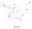
- FIG. 1is a perspective view of a motion detector system according to one exemplary embodiment of the present invention
- FIG. 2is a cross-sectional view of a Doppler radar and PIR motion sensor housing according to one exemplary embodiment of the present invention
- FIG. 3is a representative sketch of the monitored area for the Doppler radar sensor of FIGS. 1 and 2 according to one exemplary embodiment of the present invention
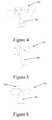
- FIGS. 4-6are perspective views of the combination Doppler radar and PIR motion sensor housing coupled to additional versions of outdoor lighting fixtures according to alternative exemplary embodiment of the present invention
- FIG. 7is a bottom view of the Doppler radar and PIR motion sensor housing of FIG. 1 according to one exemplary embodiment of the present invention
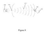
- FIG. 8is a representative diagram of Doppler shift according to one exemplary embodiment of the present invention.
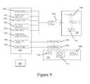
- FIG. 9is a representative table of motion detection variables for the microprocessor of the combination Doppler radar/PIR motion sensor according to one exemplary embodiment of the present invention.
- FIG. 10is a flowchart illustrating the combination Doppler radar/PIR motion sensor operation according to one exemplary embodiment of the present invention.
- the present inventionrelates to an apparatus and methods for motion detection in an outdoor environment.
- the inventionrelates to apparatus and methods for using Doppler radar in a motion detection application for an outdoor light fixture.
- the inventionmay be better understood by reading the following description of non-limiting, exemplary embodiments with reference to the attached drawings, wherein like parts of each of the figures are identified by like reference characters, and which are briefly described as follows.
- the outdoor lighting device with motion sensing/detecting capabilityincludes Doppler radar motion detection capability only. In other exemplary embodiments, the outdoor lighting device with motion sensing/detecting capability includes both Doppler radar and PIR sensors (hereinafter referred to as “dual technology”).
- the outdoor light fixture having only Doppler radaruses a proprietary microprocessor control logic which makes outdoor Doppler radar performance acceptable for the intended application.
- FIG. 1is a perspective view of a motion detector system 100 according to one exemplary embodiment of the present invention.
- the motion detector system 100includes an outdoor light fixture 110 and a combination Doppler radar and PIR motion sensor housing 180 coupled to the outdoor light fixture 110 .
- the Doppler radar and PIR motion sensor housing 180is coupled to the outdoor light fixture 110 using an extension arm 190 .
- the extension arm 190includes a thumbscrew 192 for angle adjustment of the housing 180 .
- the thumbscrew 192is rotated in one direction to allow the housing 180 to be angularly adjusted. Once the desired angle is obtained, the thumbscrew 192 is rotated in the opposite direction to tighten and fix the angular position of the housing 180 .
- the extension arm 190also includes a locknut 194 and a threaded knuckle 196 for rotational adjustment of the housing 180 and for coupling the housing 180 to the outdoor light fixture 110 .
- the threaded knuckle 196is threadedly inserted into a sensor housing opening (not shown) in a canopy 120 .
- the extension arm 190is configured to allow the Doppler radar and PIR motion sensor housing 180 to be variably positioned three dimensionally.
- extension arm 190 with the thumbscrew 192 , the locknut 194 , and the threaded knuckle 196are used to variably position the Doppler radar and PIR motion sensor housing 180 and couple the housing 180 to the outdoor light fixture 110
- other coupling devices known to people having ordinary skill in the artcan be used to couple the housing to the outdoor light fixture and/or variably position the housing with respect to the outdoor light fixture without departing from the scope and spirit of the exemplary embodiment.
- the Doppler radar and PIR motion sensor housing 180is fabricated from a heavy duty plastic. In alternative exemplary embodiments, however, the housing 180 can be fabricated using any suitable material known to those having ordinary skill in the art.
- the exemplary housing 180has one opening (not shown) that is directed towards the area to be monitored. This opening is typically covered by a lens 182
- the lens 182is an extra wide lens design and, in this exemplary embodiment, is fabricated using a translucent material. As shown in this exemplary embodiment, the lens 182 is fabricated using three lens pieces coupled together to form a lens array 183 . In alternative exemplary embodiments, the lens 182 is fabricated using greater or fewer lens pieces coupled together.
- the outdoor light fixture 110includes a canopy 120 , one or more lamp holders 130 , a reflector 140 for each of the lamp holders 130 , and a lamp 150 for insertion into each of the lamp holders 130 .
- the exemplary canopy 120is a circular mounting structure used for mounting the motion detector system 100 to a suitable mounting structure and for coupling with the lamp holders 130 and the housing 180 .
- the canopy 120includes one or more lamp holder openings (not shown) and the sensor housing opening.
- the housing 180is coupled to the canopy 120 by way of the sensor housing opening.
- the lamp holders 130are coupled to the canopy 120 using the lamp holder openings.
- the canopy 120is fabricated using a metal, a metal alloy, a polymer, or any other suitable material. Although the canopy 120 is depicted as being circular, the canopy can be any geometric or non-geometric shape without departing from the scope and spirit of the exemplary embodiment.
- the lamp holders 130are coupled to the canopy 120 using a threaded knuckle 136 and a locknut 134 .
- Each lamp holder 130includes one or more sockets (not shown) for coupling with the lamp 150 .
- the threaded knuckle 136is threadedly inserted into the lamp holder opening in the canopy 120 . Once the threaded knuckle 136 is appropriately positioned in the opening, the locknut 134 is rotated to tighten and fix the rotational position of the threaded knuckle 136 .
- the threaded knuckle 136also includes a thumbscrew 132 to adjust the angle of the lamp holder 130 .
- the thumbscrew 132is rotated in one direction to allow the lamp holder 130 to be angularly adjusted. Once the desired angle is obtained, the thumbscrew 132 is rotated in the opposite direction to tighten and fix the angular position of the lamp holder 130 .
- the threaded knuckle 136 , thumbscrew 132 , and the locknut 134are configured to allow the lamp holder 130 to be variably positioned three dimensionally.
- the threaded knuckle 136 with the thumbscrew 132 and the locknut 134are used to variably position the lamp holder 130 and couple the lamp holder 130 to the canopy 120
- other coupling devices known to people having ordinary skill in the artcan be used to couple the lamp holder to the canopy and/or variably position the lamp holder with respect to the canopy without departing from the scope and spirit of the exemplary embodiment.
- the reflector 140is coupled to the lamp holder 130 .
- the reflector 140 and the lamp holder 130are integrally formed.
- the reflector 140 and the lamp holder 130are fabricated separately and thereafter coupled to one another.
- the lamp 150is coupled to the socket in the lamp holder 130 , such that the reflector 140 surrounds the lamp 150 .
- the lamp 150can be any type of lamp, including but not limited to, an incandescent lamp, a high intensity discharge (HID) lamp, a light emitting diode (LED) lamp, a halogen lamp, a fluorescent lamp, or any other suitable type of lamp.
- an optional lens(not shown) can be disposed adjacent to the lamp 150 , so that the lamp 150 is protected from the environment.
- the lensis disposed below the lamp 150 .
- the lamp 150is coupled to the lamp holder 130 so that the lamp 150 is contained within the lamp holder 130 , the reflector 140 , and the optional lens.
- FIG. 2is a perspective, cross-sectional view of the Doppler radar and PIR motion sensor housing 180 according to one exemplary embodiment of the present invention.
- the exemplary Doppler radar and PIR motion sensor housing 180includes the lens 182 , one or more PIR sensors 210 coupled to a main circuit board 250 , a circuit barrier 220 , a Doppler radar board 230 , and a processor circuit board 270 .
- the housing 180is fabricated from a heavy duty plastic or any other suitable material known to those having ordinary skill in the art.
- the housing 180has one opening (not shown) that is directed towards the area to be monitored. This opening is covered by a lens 182 .
- the lens 182is an extra wide lens design and is fabricated using a translucent material or any other suitable material known to those having ordinary skill in the art.
- the PIR sensors 210are coupled to a main circuit board 250 and are typically oriented so that the PIR sensors 210 are located behind the lens 182 .
- the exemplary PIR sensors 210are positioned in the focal point of the lens array 183 .
- the PIR sensors 210measure infrared (IR) light radiating from objects in a field of view. Apparent motion is detected when an infrared source with one temperature passes in front of an infrared source with another temperature.
- three PIR sensors 210are positioned within the housing 180 behind the lens 182 .
- Multiple PIR sensorscan be used in some exemplary motion detector systems for enhancing the motion detection capability. In alternative exemplary embodiments, the number of PIR sensors 210 can be greater or fewer without departing from the scope and spirit of the exemplary embodiment.
- the exemplary PIR sensors 210are fabricated using technology known to those having ordinary skill in the art.
- the exemplary circuit barrier 220is a physical barrier that provides safety to a person from the internal components within the housing 180 and acts as a water barrier between the outside environment and the internal electrical components positioned within the housing 180 .
- the circuit barrier 220is provided between the lens 182 and the internal electrical components positioned within the housing 180 .
- the circuit barrier 220is molded integrally with the housing 180 ; however, other exemplary embodiments include the circuit barrier being molded as a separate component from the housing 180 .
- the circuit barrier 220is fabricated from the same material as the housing 180 .
- the circuit barrier 220is fabricated from other flame resistant and shock resistant materials, such as a metal enclosure, without departing from the scope and spirit of the exemplary embodiment.
- the Doppler radar board 230 , the main circuit board 250 , and the processor circuit board 270are positioned within the housing 180 .
- the Doppler radar board 230includes a Doppler radar sensor (not shown) having one or more antennas (not shown) for transmitting and receiving signals to and from the monitored area.
- the Doppler radar sensormakes use of the Doppler effect to produce data about objects at a distance.
- the Doppler radar sensordoes this by beaming a microwave signal towards a desired target and waiting for its reflection signal, then analyzing how the original signal has been altered by the object(s) that reflected it. Variations in the frequency of the signal give direct and highly accurate measurements of a target's velocity relative to the Doppler radar sensor and the direction of the microwave beam.
- a microprocessor(not shown) is positioned on the processor circuit board 270 and receives and analyzes signals from the PIR sensors 210 on the main circuit board 250 and the Doppler radar sensor on the Doppler radar board 230 .
- FIG. 3is a representative sketch of the monitored area 300 for the outdoor light fixture's 110 Doppler radar sensor of FIGS. 1 and 2 according to one exemplary embodiment of the present invention.
- the Doppler radar board 230is positioned at a downward angle for improved motion detection coverage.
- the downward angle 310is approximately a 10-degree down angle from the horizontal 320 ; however, the angle could be adjusted anywhere between 0-90 degrees down from the horizontal 320 depending upon the desired range of the monitored area 300 .
- Positioning the Doppler radar board 230 at a downward anglehelps detect motion at a very close range without correspondingly losing far range detection capabilities. However, positioning the Doppler radar board 230 at an angle is not required for the motion detector system 100 to function properly.
- FIGS. 4-6are perspective views of the combination Doppler radar and PIR motion sensor housing 180 coupled to additional versions of outdoor lighting fixtures 410 , 510 , and 610 according to alternative exemplary embodiments of the present invention. These are but a few of the different alternative exemplary embodiments.
- the Doppler and Doppler/PIR dual technology motion sensorsare incorporated into lighting lanterns and lantern fixtures (not shown). Outdoor lighting fixtures 410 , 510 , and 610 are similar to the outdoor light fixture 110 except for the types of lamp head design, reflectors, and/or lamps used.
- the types of lampsinclude but are not limited to, incandescent lamps, high intensity discharge (HID) lamps, light emitting diodes (LED) lamps, halogen lamps, fluorescent lamps, or any other suitable type of lamp.
- the outdoor lighting fixture 610includes a canopy 620 having a different geometric shape than canopy 120 of outdoor light fixture 110 .
- the canopy 620is oval-shaped; however, other geometric or non-geometric shapes can be used for the canopy without departing from the scope and spirit of the exemplary embodiment.
- FIG. 7is a bottom view of the Doppler radar and PIR motion sensor housing 180 of FIG. 1 according to one exemplary embodiment of the present invention.
- the exemplary housing 180includes a sensitivity setting control knob 710 and mode setting control knob 750 positioned along the bottom of the housing 180 . Positioning the control knobs 710 and 750 along the bottom of the housing 180 provides easier access for a consumer using the motion detector system 100 because the motion detector system 100 is usually installed overhead.
- control knobs 710 and 750have another shape or form, such as a sliding switch or a push button, and are positioned along other portions of the housing 180 or other portions of the outdoor light fixture 110 in general. According to the exemplary embodiment shown in FIG.
- the control knobs 710 and 750are adjusted by rotating, either clockwise or counter-clockwise, as the situation requires.
- the sensitivity setting control knob 710includes a receptacle 720 along its outer-looking face 715 , which is capable of receiving a Philips-head or other known type of screwdriver, thereby facilitating the adjustment of the sensitivity setting control knob 710 .
- the mode setting control knob 750includes a receptacle 760 along its outer-looking face 755 , which is capable of receiving a Philips-head or other known type of screwdriver, thereby facilitating the adjustment of the mode setting control knob 750 .
- the exemplary sensitivity setting control knob 710 of FIG. 7is indicated by a “+” 730 and “ ⁇ ” 735 at each end of the rotational range.
- the adjustment for the sensitivity setting control knob 710is infinite in between the “+” 730 and “ ⁇ ” 735 setting and is used to control the microprocessor's interpretation of the signal received.
- the exemplary sensitivity setting control knob 710is pointing towards the “ ⁇ ” 735 position the motion detector system 100 is operating at the lowest sensitivity.
- the exemplary sensitivity setting control knob 710is in the “+” 730 position the motion detector system 100 is operating at the maximum sensitivity.
- the exemplary mode setting control knob 750 of FIG. 7includes a test mode 770 , where the motion detector system 100 can operate day or night but the lamp 150 stays on for only a few seconds when motion is detected.
- the test mode 770is typically used during the initial setup of the motion detector system 100 for aiming purposes.
- a useris able to move around the monitored area to verify the sensitivity of the motion detector system 100 and iteratively adjust the sensitivity setting control knob 710 until the desired sensitivity is achieved.
- the “1 m through 12 m” night time settings 775represent the ability to adjust the period that the lamp 150 stays on once motion is detected.
- the rangeis between one minute and twelve minutes in the example of FIG. 7 .
- the motion detector portion of the motion detector system 100only detects motion and activates the lamp 150 when motion is detected during the period from dusk to dawn and when a range within the “1 m to 12 m” night time settings 775 is selected.
- the exemplary housing 180 of FIG. 7further includes a clear lens 780 located in between the two control knobs 710 and 750 , which is used to protect and hold the cadmium sulfide (CdS) photocell (not shown) in position.
- the CdS photocellis positioned adjacent the clear lens 780 .
- the CdS photocellis used to determine light levels in order that a determination is made as to whether it is day or night, and is found in most common motion detectors.
- a CdS photocellis used to determine light levels, other devices and/or photocells that can determine light levels, for example a clock, can be used without departing from the scope and spirit of the exemplary embodiment.
- the clear lens 780is positioned along the bottom of the housing 180 ; however, the clear lens 780 could alternatively be positioned along other portions of the housing 180 or other portions of the outdoor light fixture 110 without departing from the scope and spirit of the exemplary embodiment.
- FIG. 8is a representative diagram of Doppler shift caused by relative motion of a target 820 in the field of view of the Doppler radar sensor 810 according to one exemplary embodiment of the present invention.
- the Doppler radar sensor 810emits a microwave beam 817 from a transmitter 815 .
- the microwave beam 817is emitted at a first frequency and travels through the monitored area.
- the microwave beam 817is reflected back to the transmitter 815 by the moving target 820 .
- This reflected microwave beamhas a shift in frequency, which results in a second frequency.
- the Doppler radar sensor 810utilizes this principal.
- the amount of frequency shiftis directly proportional to the target's velocity relative to the Doppler radar sensor's transmitter 815 .
- FIG. 8presents an example of the target 820 approaching a Doppler radar sensor 810 , where the target's path forms an angle ⁇ 825 with respect to the direction of the microwave beam 817 .
- FIG. 9is a representative table of motion detection variables 900 for the microprocessor of the combination Doppler radar/PIR motion sensor according to one exemplary embodiment of the present invention.
- One or more of these motion detection variables 900are implemented in the microprocessor of the combination Doppler radar/PIR motion sensor and are adjustable based on the needs or desires of the particular implementation.
- the motion detection variables 900include radar sensitivity variable 910 , radar count threshold variable 912 , PIR sensitivity variable 914 , PIR count threshold variable 916 , time window variable 918 , temperature compensation variable 920 , ambient light control variable 950 , and lamp “on” time variable 970 .
- the sensitivity setting 930is manually adjustable using sensitivity setting control knob 710 located on the housing 180 .
- the radar sensitivity variable 910is typically set to a higher value when the sensitivity setting control knob 710 is set to a higher setting and a lower value when the sensitivity setting control knob 710 is set to a lower sensitivity setting.
- the exemplary radar sensitivity variable 910is adjustable infinitely within the range of the “+” setting 730 , or maximum sensitivity setting, and the “ ⁇ ” setting 735 , or minimum sensitivity setting.
- the radar count threshold variable 912represents the number of events needed within a window of time to trigger detection using the Doppler radar sensor. For example, if the time window variable 918 is set to three seconds and the radar count threshold variable 912 is set to four events, the Doppler radar sensor triggers detection only when four motion events have occurred within the three second window.
- the PIR sensitivity variable 914is typically set to a higher value when the sensitivity setting control knob 710 is set to a higher setting and a lower value when the sensitivity setting control knob 710 is set to a lower sensitivity setting.
- the PIR sensitivity variable 912is adjustable infinitely within the range of the “+” setting 730 , or maximum sensitivity setting, and the “ ⁇ ” setting 735 , or minimum sensitivity setting.
- the PIR count threshold variable 916represents the number of events needed within a window of time to trigger detection using the PIR sensor. For example, if the time window variable 918 is set to three seconds and the PIR count threshold variable 916 is set to three events, the PIR sensor triggers detection only when three motion events have occurred within the three second window.
- the time window variable 918further reduces the chance of false positives.
- both sensors, the Doppler radar sensor and the PIR sensorare set to require a minimum number of motion events over some period of time.
- the time window variable 918is adjusted in the software to either allow the motion detector system 100 to trigger detection the instant any motion is detected, or require the motion detector system 100 to wait until a set number of events are recorded within a set time period before triggering detection.
- the lamps 150are turned on. For example, if the radar count threshold variable 912 is set to four and the time window variable 918 is set to three seconds, the motion detector system 100 will not trigger detection until the Doppler radar sensor senses four motion events occurring within a rolling three second period of time.
- the motion detector system 100will not trigger detection until the PIR sensor senses three motion events occurring within a rolling three second period of time.
- the time window variable 918allows both increased sensitivity and improved false positive rejection. Spurious motion events are typically rejected by increasing the radar count threshold variable 912 or the PIR count threshold variable 916 , while overall sensitivity is retained by “remembering” events over some window of time, which is set by the time window variable 918 .
- using a longer time window variable 918 with a higher radar count threshold variable 912 and a higher PIR count threshold variable 916will delay detection of motion.
- the temperature compensation variable 920is used to adjust the PIR sensitivity 914 to compensate for the ambient temperature.
- the PIR sensorscreate a large signal.
- the ambient temperatureis the same as the surface temperature of bodies or their exterior clothing in the field of view, the PIR sensors do not produce a signal.
- temperature compensation variable 920automatically increases the PIR sensitivity 914 .
- the ambient temperature compensation variable 920can be turned off or on based on the particular needs and desires of the user.
- Each of the ambient light control variable 950 and the lamp “on” time variable 970is adjustable to change the motion detector system's 100 mode setting 980 .
- the mode setting 980is manually adjustable using mode setting control knob 750 located on the housing 180 .
- the mode setting control knob 750is used to select different modes, including a test mode 770 and a “1 m through 12 m” night time setting 775 .
- the ambient light control variable 950is typically turned off when the test mode 770 is selected.
- the mode setting control knob 750is at or between the exemplary 1 minute and 12 minute mode, the ambient light control variable 950 is activated.
- the motion detector system 100is capable of a setting whereby it will detect a motion event only when the ambient light is below the specified threshold set in the microprocessor.
- the lamp “on” time variable 970is used to adjust the length of on time specified when the test mode 770 is selected. However, when the “1 m through 12 m” night time setting 775 is selected, the length of lamp on time is adjustable between 1 minute and 12 minutes. However, other time periods between 1 second and 1 hour are contemplated and within the scope of the present invention. For example, when the mode setting control knob 750 is set to 1 minute, the lamp 150 stays on for one minute after sufficient motion is detected. If the mode setting control knob 750 is set half way between 1 m and 12 m, the lamp 150 stays on for approximately six minutes when sufficient motion is detected.
- a manual override 990is provided to override the “1 m through 12 m” night time setting 775 so that the lamps 150 are immediately turned on when the manual override 990 is pressed.
- the amount of time that the lamps 150 are turned onis selected by the user depending upon the setting of the “1 m through 12 m” night time setting 775 .
- the manual override 990turns the lamps 150 on for a desired time, which can be factory programmed or set by the user based upon another timing switch (not shown).
- the motion detection variables 900are adjustable using a device 905 that is either hard-wired to the motion detection system 100 or wirelessly coupled to the motion detection system 100 .
- the device 905is wirelessly coupled to the motion detection system 100 using BLUETOOTH® technology, which is a technology using a short range radio wave wireless communication device having a range limited to thirty feet.
- BLUETOOTH® technologyis a technology using a short range radio wave wireless communication device having a range limited to thirty feet.
- the motion detection system 100also includes BLUETOOTH® communication capability, whereby a consumer can make adjustments to the sensitivity settings 930 and mode settings 980 of the motion detector system 100 from their computer or BLUETOOTH® capable device 905 , which is a short range radio wave wireless communication device having a range limited to thirty feet.
- the BLUETOOTH® communication featureallows the consumer to make adjustments to the sensor features without climbing a ladder to reach the bottom of the housing 180 , such as is shown in FIG. 7 .
- the exemplary motion detector system 100also provides the ability to create custom settings, or export data, instead of requiring the consumer to use the normal pre-programmed setting(s) programmed into in the microprocessor. Accordingly, BLUETOOTH® connectivity with the microprocessor allows the consumer to perform various functions from their computer or other BLUETOOTH® capable device 905 .
- These functionsinclude, but are not limited to, adjusting Doppler radar and/or PIR sensor sensitivity of each technology independently, adjusting the window of time used for detecting motion events, adjusting the count threshold for Doppler radar and PIR sensors individually, turning on/off or adjusting the temperature compensation, adjusting the ambient light control, exporting motion detection data to a computer to record the motion events to a spreadsheet, and sending a signal to a BLUETOOTH® enabled camera that may or may not be coupled to the motion detection system 100 to record a photo or movie of the motion event to the computer, a VCR, a DVD, a DVR or other similar recording device.
- the function involving the recordation of data eventsallows recording the start/stop time of each motion event every time the motion detector system 100 detects motion plus all of the settings can be recorded at the time of the event along with the strength of signal.
- FIG. 10is a flowchart illustrating an operating method 1000 for the combination Doppler radar/PIR motion sensor according to one exemplary embodiment of the present invention.
- Those of ordinary skill in the artwill recognize that the exemplary method disclosed in FIG. 10 can be modified to include greater or fewer steps. Further, the order of the steps, as shown, in FIG. 10 is for exemplary purposes only. The order can be modified in many different ways while still achieving the objectives of the present invention.
- the operating method 1000starts at step 1005 , where the power to the motion detector system 100 is turned on.
- the power circuit(not shown), located on the main circuit board 250 within the housing 180 , is energized at step 1010 .
- the motion detector system 100is supplied power and undergoes an initial power-up at step 1015 .
- the relay or triac(not shown) is energized at step 1020 , and the lamp 150 is turned on at step 1025 .
- a determinationis made at step 1030 as to whether the lamps 150 have been on for the complete duration. This duration is pre-set at the factory, but can be changed subsequently by the user.
- the complete durationmay vary depending upon whether the motion detector system 100 is in the test mode 770 or whether it is in the 1 m-12 m setting mode 775 . If the duration is not complete, the lamps 150 remain on until the determination is made at step 1030 that the lamps 150 have been on for the complete duration. The lamps 150 are then turned off at step 1035 .
- the sensitivity 710is adjustable by the user at step 1040 .
- the motion detector system 100checks for motion within the monitored area 300 at step 1045 based upon the settings for the sensitivity 710 and the mode 750 .
- the mode setting 750is determined at step 1050 , which can be adjusted by the user.
- the mode setting 750is determined to be either test mode 770 , which is at step 1055 , or “1 m through 12 m” night time setting 775 , or auto night-time mode, which is at step 1060 .
- the mode setting control knob 755is positioned at the test mode 770 , the photocell is turned off and the motion detector system 100 checks for motion using the Doppler radar sensor at step 1070 and the PIR sensor 210 at step 1085 .
- the photocellis turned on and determines if the ambient light is below the specified threshold set in the processor at step 1065 . If the ambient light is not below the specified threshold, the determination process continuously recycles until the ambient light is below the specified threshold. When the ambient light is below the specified threshold, the motion detector system 100 checks for motion using the Doppler radar sensor at step 1070 and the PIR sensor 210 at step 1085 .
- the Doppler radar sensorstarts detecting motion at step 1070 .
- a determinationis made at step 1075 as to whether the minimum radar count threshold 912 has been achieved. If the minimum radar count threshold 912 is not achieved, the process recycles to step 1070 until it is determined that the minimum radar count threshold 912 is achieved at step 1075 .
- a determinationalso is made as to whether the minimum radar count threshold 912 was achieved within a specified time window 918 at step 1080 . If the minimum radar count threshold 912 was not achieved within the specified time window 918 , the process recycles back to step 1070 . If the minimum radar count threshold 912 was achieved within the specified time window 918 , the relay or triac is energized at step 1020 .
- the lamp 150is turned on at step 1025 .
- the lamp 150is turned off at step 1035 .
- the motion detector system 100again determines the sensitivity setting at step 1040 and begins detecting for motion at step 1045 .
- the complete duration for lamp “on” time 970is determined according to where the mode setting control knob 750 is positioned.
- the PIR sensor 210starts detecting motion at step 1085 .
- a determinationis made at step 1090 as to whether the minimum PIR count threshold 916 has been achieved. If the minimum PIR count threshold 916 is not achieved, the process recycles to step 1085 until it is determined that the minimum PIR count threshold 916 is achieved at step 1090 .
- a determinationalso is made as to whether the minimum PIR count threshold 916 was achieved within a specified time window 918 at step 1095 . If the minimum PIR count threshold 916 was not achieved within the specified time window 918 , the process recycles back to step 1085 . If the minimum PIR count threshold 916 was achieved within the specified time window 918 , the relay or triac is energized at step 1020 .
- the lamp 150is turned on at step 1025 . Once a determination is made at step 1030 that the lamp 150 has been on for the complete duration, the lamp 150 is turned off at step 1035 .
- the motion detector system 100again determines the sensitivity setting at step 1040 and begins detecting for motion at step 1045 .
- the complete duration for lamp “on” time 970is determined according to where the mode setting control knob 750 is positioned.
- the relay or triacis energized at step 1020 when either the Doppler radar sensor or the PIR sensor 210 detects that there is motion within the monitored area 300 .
Landscapes
- Engineering & Computer Science (AREA)
- Radar, Positioning & Navigation (AREA)
- Remote Sensing (AREA)
- Computer Networks & Wireless Communication (AREA)
- Physics & Mathematics (AREA)
- General Physics & Mathematics (AREA)
- General Engineering & Computer Science (AREA)
- Radar Systems Or Details Thereof (AREA)
Abstract
Description
FD=2V(F0/C)cos Ø,
Where
- F0=transmitter frequency (Hertz)
- C=velocity of light (3×10⁸meters per second)
- V=velocity of the target (meters per second)
- Ø=angle between direction of microwave beam and target's path
According to the above provided formula, if Ø is ninety degrees, which occurs when thetarget 120 is moving perpendicular to the direction of themicrowave beam 817, FDis equal to zero. Thus, there is no Doppler frequency shift. Conversely, if Ø is zero degrees, which occurs when thetarget 120 is moving parallel to the direction of themicrowave beam 817, FDis equal to 2V(F0/C). Thus, the maximum attainable Doppler frequency shift is achieved.
Claims (20)
Priority Applications (1)
| Application Number | Priority Date | Filing Date | Title |
|---|---|---|---|
| US13/561,612US8519883B2 (en) | 2008-09-30 | 2012-07-30 | Adjusting the sensitivity of a PIR sensor or a doppler radar sensor disposed within a light fixture |
Applications Claiming Priority (3)
| Application Number | Priority Date | Filing Date | Title |
|---|---|---|---|
| US10139608P | 2008-09-30 | 2008-09-30 | |
| US12/570,914US8232909B2 (en) | 2008-09-30 | 2009-09-30 | Doppler radar motion detector for an outdoor light fixture |
| US13/561,612US8519883B2 (en) | 2008-09-30 | 2012-07-30 | Adjusting the sensitivity of a PIR sensor or a doppler radar sensor disposed within a light fixture |
Related Parent Applications (1)
| Application Number | Title | Priority Date | Filing Date |
|---|---|---|---|
| US12/570,914ContinuationUS8232909B2 (en) | 2008-09-30 | 2009-09-30 | Doppler radar motion detector for an outdoor light fixture |
Publications (2)
| Publication Number | Publication Date |
|---|---|
| US20120293076A1 US20120293076A1 (en) | 2012-11-22 |
| US8519883B2true US8519883B2 (en) | 2013-08-27 |
Family
ID=42130736
Family Applications (2)
| Application Number | Title | Priority Date | Filing Date |
|---|---|---|---|
| US12/570,914Active2030-09-22US8232909B2 (en) | 2008-09-30 | 2009-09-30 | Doppler radar motion detector for an outdoor light fixture |
| US13/561,612ActiveUS8519883B2 (en) | 2008-09-30 | 2012-07-30 | Adjusting the sensitivity of a PIR sensor or a doppler radar sensor disposed within a light fixture |
Family Applications Before (1)
| Application Number | Title | Priority Date | Filing Date |
|---|---|---|---|
| US12/570,914Active2030-09-22US8232909B2 (en) | 2008-09-30 | 2009-09-30 | Doppler radar motion detector for an outdoor light fixture |
Country Status (1)
| Country | Link |
|---|---|
| US (2) | US8232909B2 (en) |
Cited By (9)
| Publication number | Priority date | Publication date | Assignee | Title |
|---|---|---|---|---|
| US20160202114A1 (en)* | 2015-01-13 | 2016-07-14 | Motorola Mobility Llc | Portable Electronic Device with Dual, Diagonal Proximity Sensors and Mode Switching Functionality |
| US10001251B2 (en)* | 2015-12-01 | 2018-06-19 | Mrp Design Engineering, Llc | Lantern |
| USD844871S1 (en) | 2015-12-01 | 2019-04-02 | Mrp Design Engineering, Llc | Lantern |
| US10438464B1 (en) | 2018-06-06 | 2019-10-08 | Ademco Inc. | Systems and methods for determining and verifying a presence of an object or an intruder in a secured area |
| TWI684778B (en)* | 2018-03-26 | 2020-02-11 | 為升電裝工業股份有限公司 | Anti-collision radar device for trailer-mounted vehicle |
| US10996325B2 (en) | 2018-11-30 | 2021-05-04 | Ademco Inc. | Systems and methods for adjusting a signal broadcast pattern of an intrusion detector |
| US11074794B2 (en) | 2018-11-30 | 2021-07-27 | Ademco Inc. | Systems and methods for activating and deactivating controlled devices in a secured area |
| US11282374B2 (en) | 2019-08-19 | 2022-03-22 | Ademco Inc. | Systems and methods for building and using a false alarm predicting model to determine whether to alert a user and/or relevant authorities about an alarm signal from a security system |
| US11859375B2 (en) | 2009-12-16 | 2024-01-02 | Kohler Co. | Touchless faucet assembly and method of operation |
Families Citing this family (63)
| Publication number | Priority date | Publication date | Assignee | Title |
|---|---|---|---|---|
| US8665138B2 (en)* | 2007-07-17 | 2014-03-04 | Laufer Wind Group Llc | Method and system for reducing light pollution |
| US8436542B2 (en) | 2009-05-04 | 2013-05-07 | Hubbell Incorporated | Integrated lighting system and method |
| US20110291570A1 (en)* | 2010-06-01 | 2011-12-01 | Saman Sinai | Energy-Efficient Luminaire with Automatic Multilevel Illumination |
| JP2012084441A (en)* | 2010-10-13 | 2012-04-26 | Panasonic Corp | Lighting system |
| US10564613B2 (en) | 2010-11-19 | 2020-02-18 | Hubbell Incorporated | Control system and method for managing wireless and wired components |
| JP2012112745A (en)* | 2010-11-24 | 2012-06-14 | Panasonic Corp | Lighting fixture with doppler sensor |
| RU2475771C1 (en)* | 2011-10-27 | 2013-02-20 | Федеральное государственное бюджетное образовательное учреждение высшего профессионального образования "Национальный исследовательский университет "МИЭТ" (МИЭТ) | Device to detect moving object |
| US11553692B2 (en) | 2011-12-05 | 2023-01-17 | Radio Systems Corporation | Piezoelectric detection coupling of a bark collar |
| US11470814B2 (en) | 2011-12-05 | 2022-10-18 | Radio Systems Corporation | Piezoelectric detection coupling of a bark collar |
| US10674709B2 (en) | 2011-12-05 | 2020-06-09 | Radio Systems Corporation | Piezoelectric detection coupling of a bark collar |
| GB2498568B (en) | 2012-01-20 | 2014-09-24 | Cp Electronics Ltd | Sensing device and method of calibration |
| US9442018B2 (en) | 2012-01-20 | 2016-09-13 | Koninklijke Philips N.V. | Method and algorithm for self-learning/auto-commissioning by multiple sensor elements for outdoor lighting application |
| US9777909B2 (en) | 2012-01-25 | 2017-10-03 | Mind Head Llc | Security lighting systems having offset brackets and rapidly deployable and reuseable low voltage security lighting systems |
| DE102012103177A1 (en)* | 2012-04-12 | 2013-10-17 | Steinel Gmbh | Outdoor sensor device and motion sensor controlled outdoor light |
| JP6041188B2 (en)* | 2012-06-01 | 2016-12-07 | パナソニックIpマネジメント株式会社 | Sensor device |
| US9192029B2 (en)* | 2013-03-14 | 2015-11-17 | Abl Ip Holding Llc | Adaptive optical distribution system |
| US10228447B2 (en) | 2013-03-15 | 2019-03-12 | Radio Systems Corporation | Integrated apparatus and method to combine a wireless fence collar with GPS tracking capability |
| US9689583B2 (en)* | 2013-09-10 | 2017-06-27 | Honeywell International Inc. | Occupancy based energy optimization systems and methods |
| US9645226B2 (en)* | 2013-12-02 | 2017-05-09 | Navico Holding As | Radar system and methods |
| AU2014357587B2 (en)* | 2013-12-03 | 2017-09-28 | Radio Systems Corporation | Threshold barrier system |
| EP2925091B1 (en)* | 2014-03-27 | 2019-09-04 | Tridonic GmbH & Co KG | Spotlight LED module and light module |
| CN104456296B (en)* | 2014-11-11 | 2016-10-05 | 春迅电子(东莞)有限公司 | LED senses lamp |
| TWM498870U (en)* | 2014-12-12 | 2015-04-11 | Ir Tec Internat Ltd | Recessed double detector |
| DE202014106073U1 (en)* | 2014-12-16 | 2016-03-17 | Tridonic Gmbh & Co Kg | Configurable motion detector |
| US10667372B2 (en)* | 2015-06-02 | 2020-05-26 | Gg Tech Products Co., Limited | Lighting system |
| US10645908B2 (en) | 2015-06-16 | 2020-05-12 | Radio Systems Corporation | Systems and methods for providing a sound masking environment |
| US10231440B2 (en) | 2015-06-16 | 2019-03-19 | Radio Systems Corporation | RF beacon proximity determination enhancement |
| DE112016005497T5 (en) | 2015-12-28 | 2018-08-09 | Eaton Intelligent Power Limited | FORECAST AND STATE MONITORING SYSTEMS FOR LUMINAIRES |
| US20170193765A1 (en)* | 2016-01-04 | 2017-07-06 | Senstar Corporation | Barrier protection and lighting system |
| US10268220B2 (en) | 2016-07-14 | 2019-04-23 | Radio Systems Corporation | Apparatus, systems and methods for generating voltage excitation waveforms |
| CN106534634A (en)* | 2016-11-08 | 2017-03-22 | 天津华来科技有限公司 | Monitoring camera |
| US10260722B2 (en) | 2016-12-02 | 2019-04-16 | Eaton Intelligent Power Limited | Sensor modules for light fixtures |
| US10121363B2 (en)* | 2016-12-27 | 2018-11-06 | Lite-On Electronics (Guangzhou) Limited | Alarm triggering method for sensor and electronic device using the same |
| WO2018157111A1 (en) | 2017-02-27 | 2018-08-30 | Radio Systems Corporation | Threshold barrier system |
| USD840586S1 (en) | 2017-10-03 | 2019-02-12 | Cooper Technologies Company | Light fixture |
| US11394196B2 (en) | 2017-11-10 | 2022-07-19 | Radio Systems Corporation | Interactive application to protect pet containment systems from external surge damage |
| US10842128B2 (en) | 2017-12-12 | 2020-11-24 | Radio Systems Corporation | Method and apparatus for applying, monitoring, and adjusting a stimulus to a pet |
| US10986813B2 (en) | 2017-12-12 | 2021-04-27 | Radio Systems Corporation | Method and apparatus for applying, monitoring, and adjusting a stimulus to a pet |
| US10514439B2 (en) | 2017-12-15 | 2019-12-24 | Radio Systems Corporation | Location based wireless pet containment system using single base unit |
| US11372077B2 (en) | 2017-12-15 | 2022-06-28 | Radio Systems Corporation | Location based wireless pet containment system using single base unit |
| US10855996B2 (en) | 2018-02-20 | 2020-12-01 | Arlo Technologies, Inc. | Encoder selection based on camera system deployment characteristics |
| US11064208B2 (en) | 2018-02-20 | 2021-07-13 | Arlo Technologies, Inc. | Transcoding in security camera applications |
| US12293583B2 (en) | 2018-02-20 | 2025-05-06 | Arlo Technologies, Inc. | Notification priority sequencing for video security |
| US10805613B2 (en) | 2018-02-20 | 2020-10-13 | Netgear, Inc. | Systems and methods for optimization and testing of wireless devices |
| US11272189B2 (en) | 2018-02-20 | 2022-03-08 | Netgear, Inc. | Adaptive encoding in security camera applications |
| US11756390B2 (en) | 2018-02-20 | 2023-09-12 | Arlo Technologies, Inc. | Notification priority sequencing for video security |
| US10742998B2 (en) | 2018-02-20 | 2020-08-11 | Netgear, Inc. | Transmission rate control of data communications in a wireless camera system |
| US11558626B2 (en) | 2018-02-20 | 2023-01-17 | Netgear, Inc. | Battery efficient wireless network connection and registration for a low-power device |
| US11102492B2 (en)* | 2018-02-20 | 2021-08-24 | Arlo Technologies, Inc. | Multi-sensor motion detection |
| US20190289263A1 (en) | 2018-03-19 | 2019-09-19 | Netgear, Inc. | Notifications by a network-connected security system based on content analysis |
| US12289202B2 (en) | 2018-03-19 | 2025-04-29 | Arlo Technologies, Inc. | Adjusting parameters in a network-connected security system based on content analysis |
| US20190333349A1 (en)* | 2018-04-25 | 2019-10-31 | Dong Guan Bright Yinhuey Lighting Co., Ltd. China | Illuminating Device With Monitoring Alarm Function |
| US10451255B1 (en)* | 2018-10-16 | 2019-10-22 | Ningbo Weitao Electrical Appliance Co., Ltd. | Outdoor garden lamp |
| WO2020169387A1 (en)* | 2019-02-22 | 2020-08-27 | Signify Holding B.V. | A luminaire, and a corresponding method |
| US11016190B2 (en)* | 2019-04-04 | 2021-05-25 | Motorola Solutions, Inc. | Apparatus, system and method for perimeter crossover dtection about a vehicle |
| US11238889B2 (en) | 2019-07-25 | 2022-02-01 | Radio Systems Corporation | Systems and methods for remote multi-directional bark deterrence |
| DE102019126496A1 (en)* | 2019-10-01 | 2021-04-01 | Steinel Gmbh | Portable control device for controlling a motion sensor |
| JP7179230B1 (en)* | 2019-11-15 | 2022-11-28 | シグニファイ ホールディング ビー ヴィ | Modification of transmit and/or receive characteristics to detect events other than human presence |
| US10969093B1 (en)* | 2020-01-20 | 2021-04-06 | Dong Guan Jia Sheng Lighting Technology Co., Ltd. China | Rotatable lamp and two cameras for detecting movement |
| US11490597B2 (en) | 2020-07-04 | 2022-11-08 | Radio Systems Corporation | Systems, methods, and apparatus for establishing keep out zones within wireless containment regions |
| CN112654112B (en)* | 2020-12-04 | 2023-04-11 | 广州震雄装饰工程有限公司 | LED control system capable of displaying in Internet of things |
| CN113496697B (en)* | 2021-09-08 | 2021-12-28 | 深圳市普渡科技有限公司 | Robot, voice data processing method, device and storage medium |
| CN118973049B (en)* | 2024-08-20 | 2025-10-03 | 惠州市蓝微电子有限公司 | A control method, system and memory for sensing and transmitting based on radar sensing optimization and data synchronous communication |
Citations (69)
| Publication number | Priority date | Publication date | Assignee | Title |
|---|---|---|---|---|
| US2649538A (en) | 1949-10-13 | 1953-08-18 | Westinghouse Air Brake Co | Space intrusion detection system |
| US3343167A (en) | 1966-10-21 | 1967-09-19 | Sperry Rand Corp | Object detection system |
| US3683379A (en) | 1970-10-21 | 1972-08-08 | Motorola Inc | Vehicle control system and equipment |
| US3689882A (en) | 1969-12-29 | 1972-09-05 | T E M I Tech Modernes Intern | Anti-crash radio detector for automotive vehicles |
| US3786507A (en) | 1971-11-11 | 1974-01-15 | C Hurd | Vehicle anti-collision system |
| US3810172A (en) | 1972-07-18 | 1974-05-07 | L Burpee | Detection system |
| US3964394A (en) | 1973-10-05 | 1976-06-22 | Bayern-Chemie Gesellschaft Fur Flugchemische Antriebe Mit Beschrankter Haftung | Pyrochemical gas generator |
| US4031534A (en) | 1976-06-01 | 1977-06-21 | The United States Of America As Represented By The Secretary Of The Navy | Noise resistant zone penetration detection system |
| US4527151A (en) | 1982-05-03 | 1985-07-02 | Sri International | Method and apparatus for intrusion detection |
| US4631516A (en) | 1985-09-03 | 1986-12-23 | Gerald Clinker | Auxiliary vehicle warning system |
| US4697184A (en) | 1984-02-09 | 1987-09-29 | Southwest Microwave | Intrusion detection radar system with amplitude and frequency carrier modulation to eliminate targets at short and long ranges |
| US4807101A (en) | 1986-02-24 | 1989-02-21 | V-Tronics Corp. | Automatic hazard light for a motor vehicle |
| US4820938A (en) | 1988-06-03 | 1989-04-11 | The Watt Watcher, Inc. | Low voltage motion sensor for activating a high voltage load |
| US4857912A (en) | 1988-07-27 | 1989-08-15 | The United States Of America As Represented By The Secretary Of The Navy | Intelligent security assessment system |
| US4902906A (en)* | 1988-06-09 | 1990-02-20 | Murphy Gordon J | Security lighting system |
| US5182502A (en)* | 1991-05-06 | 1993-01-26 | Lectron Products, Inc. | Automatic headlamp dimmer |
| US5258899A (en) | 1992-11-19 | 1993-11-02 | Kent Chen | Motion sensor lighting control |
| US5357170A (en)* | 1993-02-12 | 1994-10-18 | Lutron Electronics Co., Inc. | Lighting control system with priority override |
| US5381323A (en) | 1993-10-01 | 1995-01-10 | Regent Lighting Corporation | Sensor housing and adjustable mast arm for a swivel lighting fixture |
| GB2279791A (en) | 1993-06-12 | 1995-01-11 | Digital Audio Ltd | Motion detecting system |
| US5386210A (en) | 1991-08-28 | 1995-01-31 | Intelectron Products Company | Method and apparatus for detecting entry |
| US5430450A (en) | 1993-02-10 | 1995-07-04 | Ford Motor Company | Method and apparatus for automatically dimming motor vehicle headlights using radar signal |
| US5506715A (en)* | 1993-10-28 | 1996-04-09 | Philips Electronics North America Corporation | Lighting system having a remotely controlled electric lamp and an infrared remote controller with improved infrared filter |
| US5578988A (en) | 1994-09-16 | 1996-11-26 | C & K Systems, Inc. | Intrusion detection system having self-adjusting threshold |
| US5637964A (en)* | 1995-03-21 | 1997-06-10 | Lutron Electronics Co., Inc. | Remote control system for individual control of spaced lighting fixtures |
| US5649761A (en) | 1995-08-11 | 1997-07-22 | Larry C. Y. Lee | Motion detector with side-pivoting light fixture |
| US5662411A (en) | 1995-03-20 | 1997-09-02 | Regent Lighting Corporation | Motion activated light fixture with fixed sensor |
| US5699243A (en)* | 1995-02-02 | 1997-12-16 | Hubbell Incorporated | Motion sensing system with adaptive timing for controlling lighting fixtures |
| US5909087A (en)* | 1996-03-13 | 1999-06-01 | Lutron Electronics Co. Inc. | Lighting control with wireless remote control and programmability |
| US5936524A (en) | 1996-05-02 | 1999-08-10 | Visonic Ltd. | Intrusion detector |
| US5984513A (en)* | 1997-07-03 | 1999-11-16 | Hubbell Incorporated | Very low current microcontroller operated motion sensor |
| US6023224A (en)* | 1997-07-29 | 2000-02-08 | The Stanley Works | Door frame with integrated keyless entry system |
| US6057797A (en) | 1996-06-11 | 2000-05-02 | Robert Bosch Gmbh | Radar sensor for use in motor vehicles |
| US6069561A (en) | 1997-06-11 | 2000-05-30 | Siemens Aktiengesellschaft | Automatic lamp control device |
| US6091200A (en) | 1998-12-17 | 2000-07-18 | Lenz; Mark | Fluorescent light and motion detector with quick plug release and troubleshooting capabilities |
| US6100803A (en) | 1999-02-10 | 2000-08-08 | Chang; Wen-Hsiang | Infrared illuminative warning detector |
| US6175309B1 (en) | 2000-01-07 | 2001-01-16 | Regent Lighting Corporation | 270 degree motion sensor |
| US6191688B1 (en) | 1999-03-22 | 2001-02-20 | Honeywell International, Inc. | Power-on mask detection method for motion detectors |
| US6206340B1 (en) | 1997-07-18 | 2001-03-27 | Kohler Company | Radar devices for low power applications and bathroom fixtures |
| US6252525B1 (en) | 2000-01-19 | 2001-06-26 | Precise Flight, Inc. | Anti-collision system |
| US6263282B1 (en) | 1998-08-27 | 2001-07-17 | Lucent Technologies, Inc. | System and method for warning of dangerous driving conditions |
| US6340864B1 (en)* | 1999-08-10 | 2002-01-22 | Philips Electronics North America Corporation | Lighting control system including a wireless remote sensor |
| US6426716B1 (en) | 2001-02-27 | 2002-07-30 | Mcewan Technologies, Llc | Modulated pulse doppler sensor |
| US20020135476A1 (en) | 2001-01-31 | 2002-09-26 | Mckinney Edward C. | Sound and motion activated light controller |
| US6459476B2 (en) | 2000-03-02 | 2002-10-01 | Denso Corporation | Forward condition detecting apparatus for vehicles |
| US6465963B1 (en)* | 1999-02-16 | 2002-10-15 | Gentex Corporation | Headlight control system utilizing information from a microwave receiver |
| US6486825B1 (en) | 2001-05-02 | 2002-11-26 | Omaha Airport Authority | Runway incursion detection and warning system |
| US6677887B2 (en) | 2000-10-11 | 2004-01-13 | Southwest Microwave, Inc. | Intrusion detection radar system |
| US6741176B2 (en)* | 1999-10-02 | 2004-05-25 | Joseph Ferraro | Flood light lamp removal misorientation alarm |
| US6759954B1 (en) | 1997-10-15 | 2004-07-06 | Hubbell Incorporated | Multi-dimensional vector-based occupancy sensor and method of operating same |
| US20040135885A1 (en) | 2002-10-16 | 2004-07-15 | George Hage | Non-intrusive sensor and method |
| US6791458B2 (en) | 2001-05-22 | 2004-09-14 | Hubbell Incorporated | Dual technology occupancy sensor and method for using the same |
| US6819239B2 (en) | 2002-08-20 | 2004-11-16 | Victoria J. Bingham | Lighting security system |
| US6872948B2 (en)* | 2002-06-14 | 2005-03-29 | Eml Technologies Llc | PIR motion detector circuitry with enhanced false-activation protection |
| US6894609B2 (en) | 2001-07-17 | 2005-05-17 | Royal Thoughts, Llc | Electrical power control and sensor module for a wireless system |
| US6927541B2 (en)* | 2002-06-14 | 2005-08-09 | Eml Technologies Llc | Multimode motion-activated lighting |
| US6963180B2 (en)* | 2003-04-23 | 2005-11-08 | Gerhard Suckfull | Control apparatus for an illuminating device |
| US20060125624A1 (en) | 2004-08-18 | 2006-06-15 | Michael Ostrovsky | Passive infrared motion sensor |
| US20060286495A1 (en)* | 2005-06-21 | 2006-12-21 | Roussel Paul D | Ignition and flame supervision system for open flame gas lights |
| US7164110B2 (en)* | 2001-10-26 | 2007-01-16 | Watt Stopper, Inc. | Diode-based light sensors and methods |
| US7165864B2 (en) | 2004-05-30 | 2007-01-23 | Robert Glenn Miller | Lighting fixture with night light |
| US20070040676A1 (en) | 2005-08-22 | 2007-02-22 | John Bandringa | Low voltage occupancy sensor |
| US7242305B2 (en) | 2004-04-09 | 2007-07-10 | General Electric Company | Device and method for monitoring movement within a home |
| US7271543B1 (en)* | 2003-05-09 | 2007-09-18 | Jeffrey Jay Goldstein | Method for providing bi-level illumination in a stair well |
| US7283048B2 (en) | 2003-02-03 | 2007-10-16 | Ingrid, Inc. | Multi-level meshed security network |
| US7284880B1 (en) | 2006-08-21 | 2007-10-23 | David Steele | Security device with rotating floodlights |
| US7339471B1 (en)* | 2004-12-30 | 2008-03-04 | Cordelia Lighting, Inc. | Nighttime-controlled lighting system |
| US20080094210A1 (en) | 2006-10-17 | 2008-04-24 | Massachusetts Institute Of Technology | Platform for Ubiquitous Sensor Deployment in Occupational and Domestic Environments |
| US7439902B2 (en) | 2006-12-20 | 2008-10-21 | Glen E. Robertson | Radar controlled automatic target illumination system |
Family Cites Families (1)
| Publication number | Priority date | Publication date | Assignee | Title |
|---|---|---|---|---|
| US2279791A (en)* | 1939-12-09 | 1942-04-14 | Detroit Air Filter Co | Fire screen |
- 2009
- 2009-09-30USUS12/570,914patent/US8232909B2/enactiveActive
- 2012
- 2012-07-30USUS13/561,612patent/US8519883B2/enactiveActive
Patent Citations (72)
| Publication number | Priority date | Publication date | Assignee | Title |
|---|---|---|---|---|
| US2649538A (en) | 1949-10-13 | 1953-08-18 | Westinghouse Air Brake Co | Space intrusion detection system |
| US3343167A (en) | 1966-10-21 | 1967-09-19 | Sperry Rand Corp | Object detection system |
| US3689882A (en) | 1969-12-29 | 1972-09-05 | T E M I Tech Modernes Intern | Anti-crash radio detector for automotive vehicles |
| US3683379A (en) | 1970-10-21 | 1972-08-08 | Motorola Inc | Vehicle control system and equipment |
| US3786507A (en) | 1971-11-11 | 1974-01-15 | C Hurd | Vehicle anti-collision system |
| US3810172A (en) | 1972-07-18 | 1974-05-07 | L Burpee | Detection system |
| US3964394A (en) | 1973-10-05 | 1976-06-22 | Bayern-Chemie Gesellschaft Fur Flugchemische Antriebe Mit Beschrankter Haftung | Pyrochemical gas generator |
| US4031534A (en) | 1976-06-01 | 1977-06-21 | The United States Of America As Represented By The Secretary Of The Navy | Noise resistant zone penetration detection system |
| US4527151A (en) | 1982-05-03 | 1985-07-02 | Sri International | Method and apparatus for intrusion detection |
| US4697184A (en) | 1984-02-09 | 1987-09-29 | Southwest Microwave | Intrusion detection radar system with amplitude and frequency carrier modulation to eliminate targets at short and long ranges |
| US4631516A (en) | 1985-09-03 | 1986-12-23 | Gerald Clinker | Auxiliary vehicle warning system |
| US4807101A (en) | 1986-02-24 | 1989-02-21 | V-Tronics Corp. | Automatic hazard light for a motor vehicle |
| US4820938A (en) | 1988-06-03 | 1989-04-11 | The Watt Watcher, Inc. | Low voltage motion sensor for activating a high voltage load |
| US4902906A (en)* | 1988-06-09 | 1990-02-20 | Murphy Gordon J | Security lighting system |
| US4857912A (en) | 1988-07-27 | 1989-08-15 | The United States Of America As Represented By The Secretary Of The Navy | Intelligent security assessment system |
| US5182502A (en)* | 1991-05-06 | 1993-01-26 | Lectron Products, Inc. | Automatic headlamp dimmer |
| US5329206A (en)* | 1991-05-06 | 1994-07-12 | Lectron Products, Inc. | Automatic headlamp dimmer having improved signal discrimination and signal processing |
| US5386210A (en) | 1991-08-28 | 1995-01-31 | Intelectron Products Company | Method and apparatus for detecting entry |
| US5258899A (en) | 1992-11-19 | 1993-11-02 | Kent Chen | Motion sensor lighting control |
| US5430450A (en) | 1993-02-10 | 1995-07-04 | Ford Motor Company | Method and apparatus for automatically dimming motor vehicle headlights using radar signal |
| US5357170A (en)* | 1993-02-12 | 1994-10-18 | Lutron Electronics Co., Inc. | Lighting control system with priority override |
| GB2279791A (en) | 1993-06-12 | 1995-01-11 | Digital Audio Ltd | Motion detecting system |
| US5381323A (en) | 1993-10-01 | 1995-01-10 | Regent Lighting Corporation | Sensor housing and adjustable mast arm for a swivel lighting fixture |
| US5506715A (en)* | 1993-10-28 | 1996-04-09 | Philips Electronics North America Corporation | Lighting system having a remotely controlled electric lamp and an infrared remote controller with improved infrared filter |
| US5578988A (en) | 1994-09-16 | 1996-11-26 | C & K Systems, Inc. | Intrusion detection system having self-adjusting threshold |
| US5699243A (en)* | 1995-02-02 | 1997-12-16 | Hubbell Incorporated | Motion sensing system with adaptive timing for controlling lighting fixtures |
| US5662411A (en) | 1995-03-20 | 1997-09-02 | Regent Lighting Corporation | Motion activated light fixture with fixed sensor |
| US5637964A (en)* | 1995-03-21 | 1997-06-10 | Lutron Electronics Co., Inc. | Remote control system for individual control of spaced lighting fixtures |
| US5649761A (en) | 1995-08-11 | 1997-07-22 | Larry C. Y. Lee | Motion detector with side-pivoting light fixture |
| US5909087A (en)* | 1996-03-13 | 1999-06-01 | Lutron Electronics Co. Inc. | Lighting control with wireless remote control and programmability |
| US5936524A (en) | 1996-05-02 | 1999-08-10 | Visonic Ltd. | Intrusion detector |
| US6057797A (en) | 1996-06-11 | 2000-05-02 | Robert Bosch Gmbh | Radar sensor for use in motor vehicles |
| US6069561A (en) | 1997-06-11 | 2000-05-30 | Siemens Aktiengesellschaft | Automatic lamp control device |
| US5984513A (en)* | 1997-07-03 | 1999-11-16 | Hubbell Incorporated | Very low current microcontroller operated motion sensor |
| US6568655B2 (en) | 1997-07-18 | 2003-05-27 | Kohler Company | Radar devices for low power applications and bathroom fixtures |
| US6206340B1 (en) | 1997-07-18 | 2001-03-27 | Kohler Company | Radar devices for low power applications and bathroom fixtures |
| US6388609B2 (en) | 1997-07-18 | 2002-05-14 | Kohler Company | Radar devices for low power applications and bathroom fixtures |
| US6023224A (en)* | 1997-07-29 | 2000-02-08 | The Stanley Works | Door frame with integrated keyless entry system |
| US6759954B1 (en) | 1997-10-15 | 2004-07-06 | Hubbell Incorporated | Multi-dimensional vector-based occupancy sensor and method of operating same |
| US6263282B1 (en) | 1998-08-27 | 2001-07-17 | Lucent Technologies, Inc. | System and method for warning of dangerous driving conditions |
| US6091200A (en) | 1998-12-17 | 2000-07-18 | Lenz; Mark | Fluorescent light and motion detector with quick plug release and troubleshooting capabilities |
| US6100803A (en) | 1999-02-10 | 2000-08-08 | Chang; Wen-Hsiang | Infrared illuminative warning detector |
| US6465963B1 (en)* | 1999-02-16 | 2002-10-15 | Gentex Corporation | Headlight control system utilizing information from a microwave receiver |
| US6191688B1 (en) | 1999-03-22 | 2001-02-20 | Honeywell International, Inc. | Power-on mask detection method for motion detectors |
| US6340864B1 (en)* | 1999-08-10 | 2002-01-22 | Philips Electronics North America Corporation | Lighting control system including a wireless remote sensor |
| US6741176B2 (en)* | 1999-10-02 | 2004-05-25 | Joseph Ferraro | Flood light lamp removal misorientation alarm |
| US6175309B1 (en) | 2000-01-07 | 2001-01-16 | Regent Lighting Corporation | 270 degree motion sensor |
| US6252525B1 (en) | 2000-01-19 | 2001-06-26 | Precise Flight, Inc. | Anti-collision system |
| US6459476B2 (en) | 2000-03-02 | 2002-10-01 | Denso Corporation | Forward condition detecting apparatus for vehicles |
| US6677887B2 (en) | 2000-10-11 | 2004-01-13 | Southwest Microwave, Inc. | Intrusion detection radar system |
| US20020135476A1 (en) | 2001-01-31 | 2002-09-26 | Mckinney Edward C. | Sound and motion activated light controller |
| US6426716B1 (en) | 2001-02-27 | 2002-07-30 | Mcewan Technologies, Llc | Modulated pulse doppler sensor |
| US6486825B1 (en) | 2001-05-02 | 2002-11-26 | Omaha Airport Authority | Runway incursion detection and warning system |
| US6791458B2 (en) | 2001-05-22 | 2004-09-14 | Hubbell Incorporated | Dual technology occupancy sensor and method for using the same |
| US6894609B2 (en) | 2001-07-17 | 2005-05-17 | Royal Thoughts, Llc | Electrical power control and sensor module for a wireless system |
| US7164110B2 (en)* | 2001-10-26 | 2007-01-16 | Watt Stopper, Inc. | Diode-based light sensors and methods |
| US6872948B2 (en)* | 2002-06-14 | 2005-03-29 | Eml Technologies Llc | PIR motion detector circuitry with enhanced false-activation protection |
| US6927541B2 (en)* | 2002-06-14 | 2005-08-09 | Eml Technologies Llc | Multimode motion-activated lighting |
| US6819239B2 (en) | 2002-08-20 | 2004-11-16 | Victoria J. Bingham | Lighting security system |
| US20040135885A1 (en) | 2002-10-16 | 2004-07-15 | George Hage | Non-intrusive sensor and method |
| US7283048B2 (en) | 2003-02-03 | 2007-10-16 | Ingrid, Inc. | Multi-level meshed security network |
| US6963180B2 (en)* | 2003-04-23 | 2005-11-08 | Gerhard Suckfull | Control apparatus for an illuminating device |
| US7271543B1 (en)* | 2003-05-09 | 2007-09-18 | Jeffrey Jay Goldstein | Method for providing bi-level illumination in a stair well |
| US7242305B2 (en) | 2004-04-09 | 2007-07-10 | General Electric Company | Device and method for monitoring movement within a home |
| US7165864B2 (en) | 2004-05-30 | 2007-01-23 | Robert Glenn Miller | Lighting fixture with night light |
| US20060125624A1 (en) | 2004-08-18 | 2006-06-15 | Michael Ostrovsky | Passive infrared motion sensor |
| US7339471B1 (en)* | 2004-12-30 | 2008-03-04 | Cordelia Lighting, Inc. | Nighttime-controlled lighting system |
| US20060286495A1 (en)* | 2005-06-21 | 2006-12-21 | Roussel Paul D | Ignition and flame supervision system for open flame gas lights |
| US20070040676A1 (en) | 2005-08-22 | 2007-02-22 | John Bandringa | Low voltage occupancy sensor |
| US7284880B1 (en) | 2006-08-21 | 2007-10-23 | David Steele | Security device with rotating floodlights |
| US20080094210A1 (en) | 2006-10-17 | 2008-04-24 | Massachusetts Institute Of Technology | Platform for Ubiquitous Sensor Deployment in Occupational and Domestic Environments |
| US7439902B2 (en) | 2006-12-20 | 2008-10-21 | Glen E. Robertson | Radar controlled automatic target illumination system |
Cited By (12)
| Publication number | Priority date | Publication date | Assignee | Title |
|---|---|---|---|---|
| US11859375B2 (en) | 2009-12-16 | 2024-01-02 | Kohler Co. | Touchless faucet assembly and method of operation |
| US20160202114A1 (en)* | 2015-01-13 | 2016-07-14 | Motorola Mobility Llc | Portable Electronic Device with Dual, Diagonal Proximity Sensors and Mode Switching Functionality |
| US9903753B2 (en)* | 2015-01-13 | 2018-02-27 | Motorola Mobility Llc | Portable electronic device with dual, diagonal proximity sensors and mode switching functionality |
| US10001251B2 (en)* | 2015-12-01 | 2018-06-19 | Mrp Design Engineering, Llc | Lantern |
| USD844871S1 (en) | 2015-12-01 | 2019-04-02 | Mrp Design Engineering, Llc | Lantern |
| TWI684778B (en)* | 2018-03-26 | 2020-02-11 | 為升電裝工業股份有限公司 | Anti-collision radar device for trailer-mounted vehicle |
| US10438464B1 (en) | 2018-06-06 | 2019-10-08 | Ademco Inc. | Systems and methods for determining and verifying a presence of an object or an intruder in a secured area |
| US10996325B2 (en) | 2018-11-30 | 2021-05-04 | Ademco Inc. | Systems and methods for adjusting a signal broadcast pattern of an intrusion detector |
| US11074794B2 (en) | 2018-11-30 | 2021-07-27 | Ademco Inc. | Systems and methods for activating and deactivating controlled devices in a secured area |
| US11282374B2 (en) | 2019-08-19 | 2022-03-22 | Ademco Inc. | Systems and methods for building and using a false alarm predicting model to determine whether to alert a user and/or relevant authorities about an alarm signal from a security system |
| US11776387B2 (en) | 2019-08-19 | 2023-10-03 | Ademco Inc. | Systems and methods for building and using a false alarm predicting model to determine whether to alert a user and/or relevant authorities about an alarm signal from a security system |
| US12165499B2 (en) | 2019-08-19 | 2024-12-10 | Ademco Inc. | Systems and methods for building and using a false alarm predicting model to determine whether to alert a user and/or relevant authorities about an alarm signal from a security system |
Also Published As
| Publication number | Publication date |
|---|---|
| US20100109934A1 (en) | 2010-05-06 |
| US8232909B2 (en) | 2012-07-31 |
| US20120293076A1 (en) | 2012-11-22 |
Similar Documents
| Publication | Publication Date | Title |
|---|---|---|
| US8519883B2 (en) | Adjusting the sensitivity of a PIR sensor or a doppler radar sensor disposed within a light fixture | |
| US5473368A (en) | Interactive surveillance device | |
| US20070177384A1 (en) | Motion sensing lighting fixture | |
| EP3850916B1 (en) | Luminaire system for determining weather related information | |
| US5590953A (en) | Directable decorative lantern with motion sensor | |
| US6948831B1 (en) | Recessed light assembly adapted for use with motion detector | |
| US5128654A (en) | Preset light controller including infrared sensor operable in multiple modes | |
| US7375313B2 (en) | Aimable motion-activated lighting fixture with angulated field | |
| CA2228761C (en) | Motion detector with side-pivoting light fixture | |
| KR101291932B1 (en) | Camera of closed-circuit television with an auxiliary luminous source | |
| CA2619630C (en) | Multiple sensor lighting system | |
| US6987267B1 (en) | Lens blind feature for motion detector | |
| US9395248B2 (en) | Radiation sensing device and control circuit | |
| EP0799461A1 (en) | Infrared motion detector with 180-degree detecting range | |
| US7876056B2 (en) | Multiple sensor variable illumination level lighting system | |
| US12104775B2 (en) | Lighting system with improved sensor control | |
| JP5016445B2 (en) | lighting equipment | |
| WO1996006865A1 (en) | Infrared intrusion detector with obscuring detecting apparatus | |
| US8277071B2 (en) | Wall-mountable light fixture providing light having a particular directionality | |
| US7902508B2 (en) | Selectable field motion detector | |
| KR101208127B1 (en) | Sensitive illuminating apparatus with intelligent sensor | |
| CA2157742C (en) | Interactive surveillance device | |
| US8269628B2 (en) | Refrigeration case motion detector | |
| KR200324757Y1 (en) | Intensity of illumination linked type pyroelectric sensor bulb | |
| US20090072127A1 (en) | Adjustable shroud for adjusting a detection field associated with a detector |
Legal Events
| Date | Code | Title | Description |
|---|---|---|---|
| AS | Assignment | Owner name:COOPER TECHNOLOGIES COMPANY, TEXAS Free format text:ASSIGNMENT OF ASSIGNORS INTEREST;ASSIGNORS:DRAKE, GEORGE MICHAEL;CRIST, RYAN;FLEIG, TYLER;AND OTHERS;SIGNING DATES FROM 20091002 TO 20091217;REEL/FRAME:028780/0661 | |
| FEPP | Fee payment procedure | Free format text:PAYOR NUMBER ASSIGNED (ORIGINAL EVENT CODE: ASPN); ENTITY STATUS OF PATENT OWNER: LARGE ENTITY | |
| STCF | Information on status: patent grant | Free format text:PATENTED CASE | |
| FPAY | Fee payment | Year of fee payment:4 | |
| AS | Assignment | Owner name:EATON INTELLIGENT POWER LIMITED, IRELAND Free format text:ASSIGNMENT OF ASSIGNORS INTEREST;ASSIGNOR:COOPER TECHNOLOGIES COMPANY;REEL/FRAME:048207/0819 Effective date:20171231 | |
| AS | Assignment | Owner name:EATON INTELLIGENT POWER LIMITED, IRELAND Free format text:CORRECTIVE ASSIGNMENT TO CORRECT THE COVER SHEET TO REMOVE APPLICATION NO. 15567271 PREVIOUSLY RECORDED ON REEL 048207 FRAME 0819. ASSIGNOR(S) HEREBY CONFIRMS THE ASSIGNMENT;ASSIGNOR:COOPER TECHNOLOGIES COMPANY;REEL/FRAME:048655/0114 Effective date:20171231 | |
| AS | Assignment | Owner name:SIGNIFY HOLDING B.V., NETHERLANDS Free format text:ASSIGNMENT OF ASSIGNORS INTEREST;ASSIGNOR:EATON INTELLIGENT POWER LIMITED;REEL/FRAME:052681/0475 Effective date:20200302 | |
| MAFP | Maintenance fee payment | Free format text:PAYMENT OF MAINTENANCE FEE, 8TH YEAR, LARGE ENTITY (ORIGINAL EVENT CODE: M1552); ENTITY STATUS OF PATENT OWNER: LARGE ENTITY Year of fee payment:8 | |
| AS | Assignment | Owner name:SIGNIFY HOLDING B.V., NETHERLANDS Free format text:CORRECTIVE ASSIGNMENT TO CORRECT THE APPLICATION NUMBERS 12183490, 12183499, 12494944, 12961315, 13528561, 13600790, 13826197, 14605880, 15186648, RECORDED IN ERROR PREVIOUSLY RECORDED ON REEL 052681 FRAME 0475. ASSIGNOR(S) HEREBY CONFIRMS THE ASSIGNMENT;ASSIGNOR:EATON INTELLIGENT POWER LIMITED;REEL/FRAME:055965/0721 Effective date:20200302 | |
| MAFP | Maintenance fee payment | Free format text:PAYMENT OF MAINTENANCE FEE, 12TH YEAR, LARGE ENTITY (ORIGINAL EVENT CODE: M1553); ENTITY STATUS OF PATENT OWNER: LARGE ENTITY Year of fee payment:12 |