US8519839B2 - Alarm systems and methods for vehicle charge cords - Google Patents
Alarm systems and methods for vehicle charge cordsDownload PDFInfo
- Publication number
- US8519839B2 US8519839B2US12/430,374US43037409AUS8519839B2US 8519839 B2US8519839 B2US 8519839B2US 43037409 AUS43037409 AUS 43037409AUS 8519839 B2US8519839 B2US 8519839B2
- Authority
- US
- United States
- Prior art keywords
- alarm
- charge cord
- status
- vehicle
- coupled
- Prior art date
- Legal status (The legal status is an assumption and is not a legal conclusion. Google has not performed a legal analysis and makes no representation as to the accuracy of the status listed.)
- Expired - Fee Related, expires
Links
- 238000000034methodMethods0.000titleclaimsdescription15
- 238000004891communicationMethods0.000claimsdescription3
- 230000007704transitionEffects0.000claimsdescription2
- 230000003213activating effectEffects0.000claims2
- 230000006870functionEffects0.000description4
- 230000009471actionEffects0.000description3
- 238000010586diagramMethods0.000description3
- 230000007246mechanismEffects0.000description3
- 230000004913activationEffects0.000description1
- 230000004397blinkingEffects0.000description1
- 230000008859changeEffects0.000description1
- 238000013479data entryMethods0.000description1
- 230000005611electricityEffects0.000description1
- 238000012544monitoring processMethods0.000description1
- 230000008569processEffects0.000description1
- 230000005236sound signalEffects0.000description1
- 230000000007visual effectEffects0.000description1
Images


Classifications
- G—PHYSICS
- G08—SIGNALLING
- G08B—SIGNALLING OR CALLING SYSTEMS; ORDER TELEGRAPHS; ALARM SYSTEMS
- G08B21/00—Alarms responsive to a single specified undesired or abnormal condition and not otherwise provided for
- G08B21/18—Status alarms
- G08B21/185—Electrical failure alarms
- B—PERFORMING OPERATIONS; TRANSPORTING
- B60—VEHICLES IN GENERAL
- B60Q—ARRANGEMENT OF SIGNALLING OR LIGHTING DEVICES, THE MOUNTING OR SUPPORTING THEREOF OR CIRCUITS THEREFOR, FOR VEHICLES IN GENERAL
- B60Q9/00—Arrangement or adaptation of signal devices not provided for in one of main groups B60Q1/00 - B60Q7/00, e.g. haptic signalling
Definitions
- the following descriptiongenerally relates to alarm systems and methods associated with charge cords for plug-in electric and hybrid electric vehicles.
- Electric and hybrid electric vehiclesare gaining in popularity. Many such vehicles are so-called “plug-in” vehicles. In a plug-in vehicle, only a limited number of miles may be traveled on battery power alone. As such, the vehicle battery is typically charged from a power source such as a public or private electrical outlet that receives electricity from an electric utility.
- a power sourcesuch as a public or private electrical outlet that receives electricity from an electric utility.
- a charge cordis used to connect the vehicle utility power source to the vehicle battery such that the battery is charged to operate the vehicle.
- the vehicle charging systemtypically begins charging the vehicle battery until the battery is completely charged.
- Charge cordsusually have a first end that plugs into the vehicle at a charging port and second end that plugs into a utility power outlet. These charge cords are generally used when a vehicle is parked, such as in a garage.
- Designersalso envision a situation in which plug-in vehicles are charged at more public charging stations, such as at places of employment or commercial establishments. At such stations, the vehicle owner might supply the charge cord to be used with the utility outlet at the station.
- charge cordspresently have no mechanism for securing the charge cord to the vehicle or the utility outlet. As such, the charge cord may be subject to theft, particularly in public charging stations, and would therefore need to be replaced to continue operation of the vehicle.
- an alarm system associated with a charge cord of a plug-in vehicleincludes a sensor configured to evaluate a status of the charge cord, including a coupled status when the charge cord is coupled to the vehicle and a decoupled status when the charge cord is not coupled to the vehicle.
- the systemfurther includes an alarm interface coupled to the sensor and configured to activate an alarm when the charge cord is in the decoupled status.
- a methodis providing for alerting a user of removal of a charge cord initially coupled to a plug-in vehicle.
- the methodincludes arming an alarm system associated with the plug-in vehicle; evaluating a status of the charge cord; and alerting the user based on the status of the charge cord.
- FIG. 1is a block diagram of an alarm system for charge cords of plug-in vehicles in accordance with an exemplary embodiment
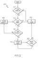
- FIG. 2is a flow chart of an exemplary method of alerting a user of charge card theft in accordance with an exemplary embodiment.
- connectionmay refer to one element/feature being directly joined to (or directly communicating with) another element/feature, and not necessarily mechanically.
- “coupled”may refer to one element/feature being directly or indirectly joined to (or directly or indirectly communicating with) another element/feature, and not necessarily mechanically.
- two elementsmay be described below, in one embodiment, as being “connected,” in alternative embodiments similar elements may be “coupled,” and vice versa.
- FIGS. 1 and 2are merely illustrative and may not be drawn to scale.
- FIG. 1is a block diagram illustrating a charge cord alarm system 100 in accordance with an exemplary embodiment.
- the system 100is typically mounted within a vehicle 110 .
- the vehicle 110may be any type of plug-in vehicle that is charged by an external source, including a plug-in electric vehicle or a plug in hybrid-electric vehicle.
- the vehicle 110may be any one of a number of different types of automobiles, such as, for example, a sedan, a wagon, a truck, or a sport utility vehicle (SUV), and may be two-wheel drive (2WD) (i.e., rear-wheel drive or front-wheel drive), four-wheel drive (4WD) or all-wheel drive (AWD).
- 2WDtwo-wheel drive
- 4WDfour-wheel drive
- ATDall-wheel drive
- the vehicle 110includes a battery 140 used to power an actuator assembly (not shown), such as a powertrain.
- the actuator assemblymay include an electric motor system that, in one embodiment, includes one or more sinusoidally-wound, three-phase alternating current (AC) motor/generators (or motors) (e.g., permanent magnet).
- ACalternating current
- DCdirect current
- the charge cord alarm system 100may also be used with different motor and/or vehicle configurations.
- the battery 140is charged with a charger 142 that includes a charging port 144 configured to receive a charge cord 130 .
- the charge cord 130couples the vehicle 110 , particularly the charger 142 , to a power source 172 via the charging port 144 . More specifically, the charge cord 130 is configured to be removably connected to the vehicle 110 at the charging port 144 , as will be discussed in further detail below.
- the charge cord 130has a utility end 134 and a vehicle end 132 .
- the vehicle 110is illustrated with the charge cord 130 about to be coupled to a utility power socket 170 associated with the utility power source 172 .
- the utility end 134may be configured to connect to a standard type of power socket or may be configured to accept adaptors for connecting to more than one type of power socket.
- the vehicle end 132 of charge cord 100is configured to connect with charging port 144 to electrically couple the vehicle charger 142 and battery 140 to the utility power source 172 .
- the utility power socket 170may be configured as any type of power socket such as 110 volt or 220 volt.
- the utility power socket 170may be located at any location, such as at a private residence, place of employment, and/or public charging station. Other voltages may also be used, such as any wall voltage available in the US or internationally.
- alarm system 100in accordance with an exemplary embodiment may deter theft of the charge cord 130 .
- the system 100includes a charge cord sensor 152 , an alarm interface 154 , an alarm system module 156 , a horn 158 , and lights 160 .
- the charge cord 120is coupled to the vehicle 110 at the charging port 144 .
- the charge cord sensor 152monitors the charging port 144 to detect the presence of the charge cord 130 .
- the charge cord sensor 152can be any hardware and/or software module with the ability to measure electrical characteristics of power flowing through charge cord 100 via the charging port 144 .
- the charge cord sensor 152may include circuits for measuring the voltage level of AC power at the charging port 144 such as a voltage meter or a voltage comparator circuit, or include circuits for measuring current flowing through charge cord 100 to vehicle 110 , such as a current meter.
- the charge cord sensor 152is a proximity sensor that detects, through a voltage divider, the presence of the charge cord 120 , even without being connected to the utility power socket 170 .
- the charge cord sensor 152sends a signal to the alarm interface 154 that indicates the presence or absence of the charge cord 130 in the charging port 144 . If the charge cord 130 is coupled to the charging port 130 , the sensor 152 indicates a connected status to the alarm interface 154 . Conversely, if the charge cord 130 is not coupled to the charging port 144 , the sensor 152 indicates a disconnected status to the alarm interface 154 . The sensor 152 can also indicate a change in status, for example, from connected to disconnected, to the alarm interface 154 .
- the alarm interface 154also receives a signal from the remote 162 .
- the remote 162may place the system 100 in one of at least two states: an armed state or a disarmed state.
- the alarm interface 154comprises a receiver (or transceiver) that is configured to receive (and/or send) information and instructions from the remote 162 , which may be a transmitter (or transceiver).
- the information connection between the remote 162 and the alarm interface 154may be of any type, including but not limited to radio waves, sound waves, lasers, infrared waves, magnetic fields, or the like.
- the remote 162may include any number or type of actuators or data entry mechanisms that allow the user to arm and disarm the system 100 .
- the remote 162is a key fob that includes a button that, when pressed, alternatively arms and disarms the system 100 .
- the remote 162may also include an information conveying device, such as a display, a light bulb, a speaker, or a vibration mechanism, that may activate and notify the user if the alarm system has been activated, as discussed in greater detail below.
- the remote 162may also be a smart keyless system, which allows a user to perform other functions associated with the vehicle 110 , including locking and unlocking the door and opening the trunk.
- the alarm interface 154may also interface with other modules in the automobile, and need not be restricted to the alarm system module 156 or alarm-related functions.
- the remote 162may include a button to remotely open or unlock the trunk or doors. These functions may be controlled by the logic in the alarm system module 156 or a different module or controller.
- the system 100may be armed by other actions related to the vehicle 110 . For example, the system 100 may be armed by locking the doors while the charge cord 130 is coupled to the vehicle.
- the alarm interface 154activates the alarm system module 156 based on the connected or disconnected status of the charge cord 130 provided by the sensor 152 and the armed or disarmed state of the system 100 provided by the remote 162 . If the system 100 is in an armed state and the status of the charge cord 130 transitions from connected to disconnected, the alarm interface activates the alarm system module 156 .
- the alarm system module 156in an activated state, will sound the horn 158 and/or flash lights 160 .
- the lights 160may be the automobile's headlights, parking lights, interior lights, and/or any other lights.
- the horn 158can be the vehicle horn or any other audible signal.
- the alarm system module 156 and/or alarm interface 154may alert the user of the alarm system 100 activation via the remote 162 .
- an actuator in the remote 162can provide a visual signal, an audio signal, and/or a tactile signal such as a buzzer.
- the usermay de-activate the alarm system 100 with the remote 162 .
- the alarm system 100may remain activated for a predetermined amount of time, such as 60 seconds or so, after which it may revert back to the armed state.
- the alarm interface 154will not activate the alarm system module 156 .
- the alarm interface 154will not activate the alarm system module 156 .
- the alarm interface 154may activate the alarm system module 156 upon the occurrence of inciting events unrelated to the charge cord 130 .
- such inciting eventmay include opening of a locked door or starting the engine during an armed state.
- the alarm interface 154 and alarm system module 156may be incorporated into, or in operable communication with, an electronic control system that may be in operable communication with battery 140 , actuator assembly (not shown), and inverter (not shown).
- the alarm interface 154 and alarm system module 156may include various sensors, automotive control modules, or electronic control units (ECUs), including logic circuitry, processor and/or memory components for carrying out the processes and methods described below.
- FIG. 2shows a flow chart according to an exemplary alarm method 200 associated with a vehicle charge cord. Reference is additionally made to FIG. 1 .
- step 205the system 100 determines whether the charge cord 130 is coupled to the charging port 144 , and thus, the vehicle 110 .
- the sensor 152determines whether or not the charge cord 130 is coupled to the vehicle 110 . If the charge cord 130 is not coupled to the charging port 144 in step 205 , the system 100 takes no action and no alarm is activated, as indicated by step 230 . If charge cord 130 is coupled to the charging port 144 in step 205 , the system 100 proceeds to step 210 in which it determines whether the system 100 is armed, for example with the remote 162 . If the system 100 is not armed in step 210 , the system 100 takes no action and no alarm is activated, as indicated by step 230 . In other embodiments, the order of steps 205 and 210 may be reversed. In other words, the system 100 only determines whether the charge cord 130 is coupled to the charging port 144 if the vehicle 110 is armed.
- step 215the system 100 determines if the charge cord 130 has been disconnected.
- the sensor 152sends a signal to the alarm interface 154 about the presence or absence of the charge cord 130 . If in step 215 , the charge cord 130 is still coupled to the socket 144 , the method 200 proceeds to step 235 , in which monitoring is maintained, and subsequently to step 210 , in which it is again determined whether or not the system 100 is armed. However, if in step 220 , the charge cord 130 has been removed from the socket 144 , the method proceeds to step 220 in which an alarm is sounded.
- the alarmcan include a honking of the horn 158 and blinking of lights 160 of the vehicle 110 .
- the system 100may also send a notification to the user of the vehicle 110 .
- the system 100determines whether the user has disarmed the system 100 , for example, with the remote 162 . If yes in step 225 , the system 100 turns off the alarm in step 230 . If no in step 225 , the system 100 continues the alarm, as indicated by the return to step 220 .
Landscapes
- Engineering & Computer Science (AREA)
- Human Computer Interaction (AREA)
- Mechanical Engineering (AREA)
- Business, Economics & Management (AREA)
- Emergency Management (AREA)
- Physics & Mathematics (AREA)
- General Physics & Mathematics (AREA)
- Burglar Alarm Systems (AREA)
- Electric Propulsion And Braking For Vehicles (AREA)
Abstract
Description
Claims (19)
Priority Applications (3)
| Application Number | Priority Date | Filing Date | Title |
|---|---|---|---|
| US12/430,374US8519839B2 (en) | 2009-04-27 | 2009-04-27 | Alarm systems and methods for vehicle charge cords |
| DE102010017934ADE102010017934A1 (en) | 2009-04-27 | 2010-04-22 | Alarm systems and methods for vehicle charging cables |
| CN201010170342ACN101872523A (en) | 2009-04-27 | 2010-04-27 | The warning system and the method that are used for the Vehicular charging cable |
Applications Claiming Priority (1)
| Application Number | Priority Date | Filing Date | Title |
|---|---|---|---|
| US12/430,374US8519839B2 (en) | 2009-04-27 | 2009-04-27 | Alarm systems and methods for vehicle charge cords |
Publications (2)
| Publication Number | Publication Date |
|---|---|
| US20100271192A1 US20100271192A1 (en) | 2010-10-28 |
| US8519839B2true US8519839B2 (en) | 2013-08-27 |
Family
ID=42991644
Family Applications (1)
| Application Number | Title | Priority Date | Filing Date |
|---|---|---|---|
| US12/430,374Expired - Fee RelatedUS8519839B2 (en) | 2009-04-27 | 2009-04-27 | Alarm systems and methods for vehicle charge cords |
Country Status (3)
| Country | Link |
|---|---|
| US (1) | US8519839B2 (en) |
| CN (1) | CN101872523A (en) |
| DE (1) | DE102010017934A1 (en) |
Cited By (3)
| Publication number | Priority date | Publication date | Assignee | Title |
|---|---|---|---|---|
| US20130187617A1 (en)* | 2012-01-25 | 2013-07-25 | Sony Mobile Communications Ab | Theft protection |
| US8725330B2 (en) | 2010-06-02 | 2014-05-13 | Bryan Marc Failing | Increasing vehicle security |
| US20190344669A1 (en)* | 2018-05-09 | 2019-11-14 | Byton North America Corporation | Safe and secure charging of a vehicle |
Families Citing this family (19)
| Publication number | Priority date | Publication date | Assignee | Title |
|---|---|---|---|---|
| US8712648B2 (en) | 2011-03-08 | 2014-04-29 | Gm Global Technology Operations | Passive charge cord release system for an electric vehicle |
| US8690591B2 (en) | 2011-06-09 | 2014-04-08 | GM Global Technology Operations LLC | Electric vehicle with secondary charge cord release mechanism |
| US20130015814A1 (en)* | 2011-07-13 | 2013-01-17 | Tesla Motors, Inc. | Charge Disruption Monitoring and Notification System |
| US9030309B2 (en)* | 2011-08-08 | 2015-05-12 | GM Global Technology Operations LLC | System for monitoring items in proximity to a vehicle |
| CN103238261B (en)* | 2011-08-26 | 2016-03-16 | 松下知识产权经营株式会社 | Vehicle-mounted charging device |
| US8936482B2 (en) | 2011-11-30 | 2015-01-20 | GM Global Technology Operations LLC | High voltage safety lock sensing—single sensor linear actuator |
| US9368008B2 (en) | 2012-05-30 | 2016-06-14 | Schneider Electric USA, Inc. | Electric vehicle supply equipment cable detection |
| TWI467884B (en)* | 2012-08-20 | 2015-01-01 | 台達電子工業股份有限公司 | Anti-theft charaging system |
| US8947247B2 (en)* | 2012-11-27 | 2015-02-03 | Semaconnect, Inc. | System and method for detecting and preventing cable theft in electric vehicle supply equipment |
| US8976016B2 (en)* | 2013-03-07 | 2015-03-10 | GM Global Technology Operations LLC | Electrical charging system alarm for a vehicle charge cord with automatic shutoff |
| US20140267712A1 (en)* | 2013-03-15 | 2014-09-18 | Eaton Corporation | Theft alert system for electric vehicle charging cable |
| JP5772862B2 (en)* | 2013-04-10 | 2015-09-02 | 株式会社デンソー | Charge control device |
| JP5937542B2 (en)* | 2013-05-15 | 2016-06-22 | 株式会社城南製作所 | Vehicle cover opening / closing control device |
| CN104340115B (en)* | 2013-07-23 | 2018-07-06 | 标致雪铁龙(中国)汽车贸易有限公司 | For the system for prompting and based reminding method of electric vehicle |
| US9302609B2 (en)* | 2014-03-28 | 2016-04-05 | GM Global Technology Operations LLC | Enhanced charge port door reminder for a fuel or charge consuming device |
| KR101736998B1 (en)* | 2016-02-01 | 2017-05-17 | 현대자동차주식회사 | Electric vehicle charging connector anti-theft method and apparatus |
| DE102016221350B4 (en)* | 2016-10-28 | 2025-06-18 | Bayerische Motoren Werke Aktiengesellschaft | Electric vehicle with charging cable detection device |
| DE102020206067A1 (en) | 2020-05-13 | 2021-11-18 | Volkswagen Aktiengesellschaft | Charging device for an electrically powered motor vehicle and method for theft detection |
| DE102021120892A1 (en) | 2021-08-11 | 2023-02-16 | Cariad Se | Method for triggering an alarm function in the event of improper use of a charging cable, control device and motor vehicle |
Citations (7)
| Publication number | Priority date | Publication date | Assignee | Title |
|---|---|---|---|---|
| JPH10178701A (en) | 1996-12-18 | 1998-06-30 | Honda Motor Co Ltd | Abnormality detection device for charging cable in electric vehicle |
| US5903064A (en)* | 1994-07-04 | 1999-05-11 | Vattenfall Ab (Public) | Distribution network and method and device for regulating electric current from the network |
| CN201057571Y (en) | 2007-03-23 | 2008-05-07 | 桂盟企业股份有限公司 | Vehicle anti-theft warning device |
| US7595607B2 (en)* | 2005-12-20 | 2009-09-29 | General Electric Company | Battery charging system and methods |
| US20100188199A1 (en)* | 2007-07-18 | 2010-07-29 | Toyota Jidosha Kabushiki Kaisha | Antitheft device, electronic control unit, antitheft security system, and antitheft method |
| US7886857B2 (en)* | 2008-06-05 | 2011-02-15 | Toyota Jidosha Kabushiki Kaisha | Vehicle equipped with electrical storage device, and charging cable |
| US20110175569A1 (en)* | 2008-08-18 | 2011-07-21 | Austin Christopher B | Vehicular batery charger, charging system, and method |
Family Cites Families (1)
| Publication number | Priority date | Publication date | Assignee | Title |
|---|---|---|---|---|
| JP3214045B2 (en)* | 1992-03-27 | 2001-10-02 | 株式会社明電舎 | Charging device |
- 2009
- 2009-04-27USUS12/430,374patent/US8519839B2/ennot_activeExpired - Fee Related
- 2010
- 2010-04-22DEDE102010017934Apatent/DE102010017934A1/ennot_activeWithdrawn
- 2010-04-27CNCN201010170342Apatent/CN101872523A/enactivePending
Patent Citations (7)
| Publication number | Priority date | Publication date | Assignee | Title |
|---|---|---|---|---|
| US5903064A (en)* | 1994-07-04 | 1999-05-11 | Vattenfall Ab (Public) | Distribution network and method and device for regulating electric current from the network |
| JPH10178701A (en) | 1996-12-18 | 1998-06-30 | Honda Motor Co Ltd | Abnormality detection device for charging cable in electric vehicle |
| US7595607B2 (en)* | 2005-12-20 | 2009-09-29 | General Electric Company | Battery charging system and methods |
| CN201057571Y (en) | 2007-03-23 | 2008-05-07 | 桂盟企业股份有限公司 | Vehicle anti-theft warning device |
| US20100188199A1 (en)* | 2007-07-18 | 2010-07-29 | Toyota Jidosha Kabushiki Kaisha | Antitheft device, electronic control unit, antitheft security system, and antitheft method |
| US7886857B2 (en)* | 2008-06-05 | 2011-02-15 | Toyota Jidosha Kabushiki Kaisha | Vehicle equipped with electrical storage device, and charging cable |
| US20110175569A1 (en)* | 2008-08-18 | 2011-07-21 | Austin Christopher B | Vehicular batery charger, charging system, and method |
Non-Patent Citations (1)
| Title |
|---|
| Chinese Office Action, dated Feb. 29, 2012, for Chinese Patent Application No. 201010170342.X. |
Cited By (9)
| Publication number | Priority date | Publication date | Assignee | Title |
|---|---|---|---|---|
| US8725330B2 (en) | 2010-06-02 | 2014-05-13 | Bryan Marc Failing | Increasing vehicle security |
| US8841881B2 (en) | 2010-06-02 | 2014-09-23 | Bryan Marc Failing | Energy transfer with vehicles |
| US9114719B1 (en) | 2010-06-02 | 2015-08-25 | Bryan Marc Failing | Increasing vehicle security |
| US9393878B1 (en) | 2010-06-02 | 2016-07-19 | Bryan Marc Failing | Energy transfer with vehicles |
| US10124691B1 (en) | 2010-06-02 | 2018-11-13 | Bryan Marc Failing | Energy transfer with vehicles |
| US11186192B1 (en) | 2010-06-02 | 2021-11-30 | Bryan Marc Failing | Improving energy transfer with vehicles |
| US20130187617A1 (en)* | 2012-01-25 | 2013-07-25 | Sony Mobile Communications Ab | Theft protection |
| US20190344669A1 (en)* | 2018-05-09 | 2019-11-14 | Byton North America Corporation | Safe and secure charging of a vehicle |
| US11117484B2 (en)* | 2018-05-09 | 2021-09-14 | Byton Limited | Safe and secure charging of a vehicle |
Also Published As
| Publication number | Publication date |
|---|---|
| DE102010017934A1 (en) | 2010-12-30 |
| CN101872523A (en) | 2010-10-27 |
| US20100271192A1 (en) | 2010-10-28 |
Similar Documents
| Publication | Publication Date | Title |
|---|---|---|
| US8519839B2 (en) | Alarm systems and methods for vehicle charge cords | |
| CN107020960B (en) | Antitheft method and apparatus for charging connector of electric vehicle | |
| US8321081B2 (en) | Plug-in vehicle management system | |
| US20110199238A1 (en) | Method and system for indicating a location of a vehicle | |
| JPH10178701A (en) | Abnormality detection device for charging cable in electric vehicle | |
| US9919682B2 (en) | Remote function device and associated wireless security sensor for a vehicle having a data communications bus and related methods | |
| CN110816317A (en) | Vehicle-mounted control system and vehicle | |
| US9656631B1 (en) | Remote function control system with wireless databus device and associated wireless security sensor for a vehicle having a data communications bus and related methods | |
| US11142165B2 (en) | Vehicle system including remote start data bus command sending based upon a short-range link and related methods | |
| CA2951679C (en) | Remote function control system with remote function device and associated wireless security sensor for a vehicle having a data communications bus and related methods | |
| CA2974521C (en) | Vehicle system including security unit providing degradation commands via a vehicle data bus and related methods | |
| CN102350980A (en) | Distributed electronic burglar alarm for car and antitheft method thereof | |
| CN101468640B (en) | Intelligent vehicle-mounted battery with alarm function and vehicle with intelligent vehicle-mounted battery | |
| CN220682073U (en) | Tractor monitoring device and tractor | |
| CN111976600A (en) | Automobile door unclosed reminding alarm system and working method thereof | |
| US8164421B2 (en) | Adaptive remote verification of vehicular functions | |
| CN212289658U (en) | The car door is not closed to remind the alarm system | |
| CA3062636C (en) | Vehicle system including remote start data bus command sending based upon a short-range link and related methods | |
| JP5803611B2 (en) | Vehicle theft prevention device and vehicle theft prevention system | |
| CN203020270U (en) | Vehicle anti-theft device | |
| CN201784576U (en) | Sensing type anti-theft system for vehicle | |
| JP4447581B2 (en) | Control device for hybrid vehicle | |
| JP2008290504A (en) | Vehicle anti-theft device | |
| CN212373334U (en) | A sensing sensor anti-theft alarm device, system and vehicle | |
| CN103507753B (en) | A kind of alarms and security systems for automobiles and automobile |
Legal Events
| Date | Code | Title | Description |
|---|---|---|---|
| AS | Assignment | Owner name:GM GLOBAL TECHNOLOGY OPERATIONS, INC., MICHIGAN Free format text:ASSIGNMENT OF ASSIGNORS INTEREST;ASSIGNOR:MITUTA, ANDRES V.;REEL/FRAME:022599/0269 Effective date:20090414 | |
| AS | Assignment | Owner name:UNITED STATES DEPARTMENT OF THE TREASURY, DISTRICT Free format text:SECURITY AGREEMENT;ASSIGNOR:GM GLOBAL TECHNOLOGY OPERATIONS, INC.;REEL/FRAME:023201/0118 Effective date:20090710 | |
| AS | Assignment | Owner name:UAW RETIREE MEDICAL BENEFITS TRUST, MICHIGAN Free format text:SECURITY AGREEMENT;ASSIGNOR:GM GLOBAL TECHNOLOGY OPERATIONS, INC.;REEL/FRAME:023162/0048 Effective date:20090710 | |
| AS | Assignment | Owner name:GM GLOBAL TECHNOLOGY OPERATIONS, INC., MICHIGAN Free format text:RELEASE BY SECURED PARTY;ASSIGNOR:UNITED STATES DEPARTMENT OF THE TREASURY;REEL/FRAME:025246/0056 Effective date:20100420 | |
| AS | Assignment | Owner name:GM GLOBAL TECHNOLOGY OPERATIONS, INC., MICHIGAN Free format text:RELEASE BY SECURED PARTY;ASSIGNOR:UAW RETIREE MEDICAL BENEFITS TRUST;REEL/FRAME:025315/0091 Effective date:20101026 | |
| AS | Assignment | Owner name:WILMINGTON TRUST COMPANY, DELAWARE Free format text:SECURITY AGREEMENT;ASSIGNOR:GM GLOBAL TECHNOLOGY OPERATIONS, INC.;REEL/FRAME:025324/0555 Effective date:20101027 | |
| AS | Assignment | Owner name:GM GLOBAL TECHNOLOGY OPERATIONS LLC, MICHIGAN Free format text:CHANGE OF NAME;ASSIGNOR:GM GLOBAL TECHNOLOGY OPERATIONS, INC.;REEL/FRAME:025781/0299 Effective date:20101202 | |
| FEPP | Fee payment procedure | Free format text:PAYOR NUMBER ASSIGNED (ORIGINAL EVENT CODE: ASPN); ENTITY STATUS OF PATENT OWNER: LARGE ENTITY | |
| STCF | Information on status: patent grant | Free format text:PATENTED CASE | |
| AS | Assignment | Owner name:GM GLOBAL TECHNOLOGY OPERATIONS LLC, MICHIGAN Free format text:RELEASE BY SECURED PARTY;ASSIGNOR:WILMINGTON TRUST COMPANY;REEL/FRAME:034185/0789 Effective date:20141017 | |
| FPAY | Fee payment | Year of fee payment:4 | |
| FEPP | Fee payment procedure | Free format text:MAINTENANCE FEE REMINDER MAILED (ORIGINAL EVENT CODE: REM.); ENTITY STATUS OF PATENT OWNER: LARGE ENTITY | |
| LAPS | Lapse for failure to pay maintenance fees | Free format text:PATENT EXPIRED FOR FAILURE TO PAY MAINTENANCE FEES (ORIGINAL EVENT CODE: EXP.); ENTITY STATUS OF PATENT OWNER: LARGE ENTITY | |
| STCH | Information on status: patent discontinuation | Free format text:PATENT EXPIRED DUE TO NONPAYMENT OF MAINTENANCE FEES UNDER 37 CFR 1.362 | |
| FP | Lapsed due to failure to pay maintenance fee | Effective date:20210827 |