US8519674B2 - Method for estimating battery degradation in a vehicle battery pack - Google Patents
Method for estimating battery degradation in a vehicle battery packDownload PDFInfo
- Publication number
- US8519674B2 US8519674B2US12/617,050US61705009AUS8519674B2US 8519674 B2US8519674 B2US 8519674B2US 61705009 AUS61705009 AUS 61705009AUS 8519674 B2US8519674 B2US 8519674B2
- Authority
- US
- United States
- Prior art keywords
- soc
- battery
- event
- time
- charge
- Prior art date
- Legal status (The legal status is an assumption and is not a legal conclusion. Google has not performed a legal analysis and makes no representation as to the accuracy of the status listed.)
- Expired - Fee Related, expires
Links
Images


Classifications
- G—PHYSICS
- G01—MEASURING; TESTING
- G01R—MEASURING ELECTRIC VARIABLES; MEASURING MAGNETIC VARIABLES
- G01R31/00—Arrangements for testing electric properties; Arrangements for locating electric faults; Arrangements for electrical testing characterised by what is being tested not provided for elsewhere
- G01R31/36—Arrangements for testing, measuring or monitoring the electrical condition of accumulators or electric batteries, e.g. capacity or state of charge [SoC]
- G01R31/392—Determining battery ageing or deterioration, e.g. state of health
- G—PHYSICS
- G01—MEASURING; TESTING
- G01R—MEASURING ELECTRIC VARIABLES; MEASURING MAGNETIC VARIABLES
- G01R31/00—Arrangements for testing electric properties; Arrangements for locating electric faults; Arrangements for electrical testing characterised by what is being tested not provided for elsewhere
- G01R31/36—Arrangements for testing, measuring or monitoring the electrical condition of accumulators or electric batteries, e.g. capacity or state of charge [SoC]
- G01R31/367—Software therefor, e.g. for battery testing using modelling or look-up tables
Definitions
- the present inventiongenerally relates to battery degradation and, more particularly, to methods for estimating or predicting battery degradation or state-of-health (SOH) in a vehicle battery pack.
- SOHstate-of-health
- the battery packis an important element to the operation of the vehicle.
- the battery packis an important element to the operation of the vehicle.
- SOHstate-of-health
- directly measuring battery degradation or the state-of-health (SOH) of the batterycan be difficult or impractical, whereas estimating or predicting battery degradation or the state-of-health (SOH) may be preferred.
- a method for estimating battery degradation in a vehicle battery packmay comprise the steps of: (a) receiving one or more battery conditions; (b) performing a time-based algorithm, wherein the time-based algorithm provides a time-based output; (c) performing an event-based algorithm, wherein the event-based algorithm extracts certain data from the battery conditions, uses the extracted data as an event-based input, and provides an event-based output in response to the event-based input; and (d) using the time-based output from the time-based algorithm and the event-based output from the event-based algorithm to estimate battery degradation in the vehicle battery pack.
- a method for estimating battery degradation in a vehicle battery packmay comprise the steps of: (a) receiving one or more battery conditions; (b) providing the battery conditions to an event-based sub-routine, wherein the event-based sub-routine comprises the steps of: (i) evaluating the battery conditions and identifying a state-of-charge (SOC) extremity and an SOC breakthrough; (ii) using the SOC extremity and the SOC breakthrough to determine an SOC swing ( ⁇ SOC); and (iii) returning the SOC swing ( ⁇ SOC) as an event-based input; (c) providing the event-based input to a data structure that correlates the event-based input to battery degradation and returns output that is used to form an event-based output; and (d) using the event-based output from the event-based algorithm to estimate battery degradation in the vehicle battery pack.
- SOCstate-of-charge
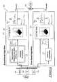
- FIG. 1is a schematic block diagram of an exemplary battery system
- FIG. 2is a schematic illustration of an exemplary method that may be used to estimate or predict battery degradation and may be used with the exemplary system of FIG. 1 ;
- FIG. 3is a flowchart of an exemplary method that may be used to extract certain data from battery conditions provided by battery sensors and may provide the extracted data to the exemplary method illustrated in FIG. 2 ;
- FIG. 4is a chart that illustrates some of the aspects of the exemplary method shown in FIG. 3 .
- FIG. 1there is shown a general and schematic view of an exemplary battery system 10 that includes a battery pack having a number of individual battery cells.
- the method described belowgathers information from two or more battery cells—for instance, information regarding the state-of-charge (SOC), temperature and/or other cell characteristics—and uses that information to estimate or predict battery degradation.
- SOCstate-of-charge
- temperaturetemperature
- BEVsbattery electrical vehicles
- the present methodmay be used with any type of vehicle battery pack, including those found in hybrid electric vehicles, plug-in hybrid electric vehicles (PHEVs), and battery electrical vehicles (BEVs), to name but a few. It is even possible to use the present method with other non-vehicle battery packs, such as those employed by uninterruptible power supplies, for instance.
- battery system 10includes a battery pack 14 , battery sensors 16 , and a battery control module 18 .
- Battery pack 14provides the vehicle with electrical power and, depending on the particular embodiment, may be the primary vehicle power source or may be used in conjunction with another power source.
- Battery pack 14includes a collection of individual battery cells 20 that are connected in series, parallel, or a combination of both in order to deliver a desired voltage, amperage, capacity, power density, and/or other performance characteristics.
- battery pack 14includes: all types of lithium-ion (e.g., lithium iron phosphate, lithium nickel manganese cobalt, lithium iron sulfide, lithium polymer, etc.), lead-acid, advanced lead-acid, nickel metal hydride (NiMH), nickel cadmium (NiCd), zinc bromide, sodium nickel chloride (NaNiCl), zinc air, vanadium redox, and others.
- Battery pack 14may provide approximately 40-600V, depending on its particular design and application. For example, a heavy truck using a two-mode hybrid system may require a high voltage battery pack capable of providing about 350V, where a lighter vehicle may only need about 200V.
- the battery system 10may be part of a belt-alternator-starter (BAS) or BAS-plus type system and thus only require a battery pack that provides about 40-110V.
- battery pack 14should be designed to withstand repeated charge and discharge cycles. Skilled artisans will appreciate that the system and method described herein are not limited to any one particular type of battery or battery arrangement, as a number of different battery embodiments could be used.
- Battery sensors 16may include any combination of hardware and/or software techniques capable of monitoring, sensing or otherwise determining battery conditions such as state of charge (SOC), temperature, voltage, current, capacitance, etc.
- battery sensors 16include a temperature sensor 30 , voltage sensor 32 , current sensor 34 , and capacitance sensor 36 .
- Battery sensors 16may be integrated within battery pack 14 (e.g., an intelligent or smart battery), they may be external sensors located outside of the battery pack (as schematically shown in FIG. 1 ), or they may be provided according to some other arrangement.
- Battery sensors 16may monitor, sense or otherwise determine battery conditions for one or more individual cells, for a collection or block of cells within battery pack 14 (i.e., a subset of the overall collection of cells), for the entire battery pack, or according to some other method known in the art. Measuring battery conditions for an individual cell (e.g., V Cell , SOC Cell , T Cell ) may be beneficial if, for example, the middle cells experience different temperatures or other battery conditions than the edge or boundary cells of battery pack 14 . The same principal of determining battery temperature on a cell-by-cell, collective or other basis also applies to battery voltage, battery current, battery capacitance, or any other battery condition.
- Battery sensors 16may employ any type of suitable technique or method for measurement, estimation, evaluation, etc.; this includes both directly and indirectly determining battery conditions. Output from battery sensors 16 may be provided to battery control module 18 or some other appropriate device via a suitable vehicle communications connection 72 (e.g, a CAN bus, a SPI connection, etc.).
- a suitable vehicle communications connection 72e.g, a CAN bus, a SPI connection, etc.
- Battery control module 18may include any variety of electronic processing devices, memory devices, input/output (I/O) devices, and/or other known techniques, and may perform various control and/or communication related functions.
- battery control module 18includes an electronic memory device 50 that stores various sensor readings (e.g., sensor readings from sensors 30 , 32 , 34 , 36 , etc.), look up tables or other data structures, algorithms, etc.
- memory device 50can store pertinent battery characteristics and background information pertaining to the battery's cell chemistry, cell capacity, upper and lower battery voltage limits, battery current limits, battery temperature limits, temperature profiles, battery impedance, number or history of charge/discharge cycles, etc.
- battery control module 18also includes a processor device 52 (e.g., a microprocessor, a microcontroller, an application specific integrated circuit (ASIC), etc.) that executes instructions for software, firmware, programs, algorithms, scripts, etc. that are stored in memory device 50 and may govern the processes and methods described herein.
- Battery control module 18can be electronically connected to other vehicle devices and modules via a suitable vehicle communications connection 76 and can interact with them when required. These are, of course, only some of the possible arrangements, functions and capabilities of battery control module 18 , as other embodiments could also be used.
- battery control module 18may be a stand-alone vehicle electronic module, it may incorporated or included within another vehicle electronic module (e.g., a power train control module or a hybrid control module), or it may be part of a larger network or system (e.g., a battery management system (BMS), a vehicle energy management system, etc.), to name a few possibilities.
- Battery control module 18may also be part of or interact with a system that determines a desired hybrid operating mode (e.g., accelerating, braking, idling, stopping, etc.) and may implement electrical power management actions accordingly.
- a desired hybrid operating modee.g., accelerating, braking, idling, stopping, etc.
- Many different battery types and arrangementsmay be used with the method described below; for instance, the battery pack 14 , battery sensors 16 , and control module 18 may all be integrated and included within one package or they could be separate techniques.
- FIG. 2there is shown a general illustration of an exemplary method 200 that may be used to estimate or predict one or more aspects of battery degradation (e.g., the state of health (SOH) of one or more battery cells).
- SOHstate of health
- the state of health (SOH) of a batterycan involve a comparison of the battery's current condition compared to the battery's ideal condition (e.g., a new battery), and can be measured according to a number of different techniques (different battery makers sometimes measure SOH differently).
- SOHstate of health
- Method 200estimates or predicts battery degradation, also known as the state-of-health (SOH), using two different algorithms: a time-based algorithm 202 and an event-based algorithm 204 .
- SOHstate-of-health
- the time-based algorithm 202receives the battery conditions on a periodic basis (e.g., once per millisecond, once per second, etc.), uses the battery conditions as a time-based input, and provides a time-based output in response to the time-based input.
- the event-based algorithm 204receives the battery conditions on a periodic basis, extracts certain data from the battery conditions (e.g., SOC extremities, SOC breakthroughs, etc.), uses the extracted data as an event-based input, and provides an event-based output in response to the event-based input. The time-based output and the event-based output are then combined when estimating battery degradation in the vehicle battery pack.
- certain datae.g., SOC extremities, SOC breakthroughs, etc.
- the time-based output and the event-based outputare then combined when estimating battery degradation in the vehicle battery pack.
- the time-based algorithm 202may not take into consideration certain intra-sampling events that can occur, as it simply uses the periodically sampled battery conditions as the time-based input for its algorithms, look-up tables, etc. It is possible, for example, for the time-based algorithm 202 to miss certain battery conditions if they occur in between sampling events (e.g., if cell SOC readings are taken every second and a cell SOC were to momentarily peak in between readings, then this information may not be captured or noticed by time-based algorithm 202 ).
- the event-based algorithm 204extracts certain data from the battery conditions—like SOC extremities and SOC breakthroughs, as will be explained—and may capture such a momentary event.
- Method 200determines one or more battery conditions, and may do so according to a variety of different techniques.
- battery conditionsare gathered, acquired or otherwise determined whenever the vehicle is ‘on’ (this may include times when the battery is charging, discharging and/or is idle) and at to a sampling rate that may be a static or a dynamic rate.
- the sampling rate(and conversely the amount of time in between readings) is altered or modified in order to accommodate the battery conditions. For example, if the battery conditions become quite volatile such that they are changing at a relatively rapid pace, then it may be preferable to increase the sampling rate so that the battery conditions are monitored more frequently. The sampling rate may be reduced at a later time once the battery conditions become more stabilized.
- Battery control module 18could even control the sampling rate of battery sensors 16 in order to manage the resources of memory device 50 and processor device 52 in an optimum fashion.
- the battery conditionsmay be determined on a cell-by-cell basis (e.g., a voltage reading could be obtained for every battery cell 20 ), on a cell group-by-cell group basis (e.g., an average voltage reading could be determined for a group or block of battery cells), on a representative cell basis (e.g., a worst or best case battery cell, a randomly selected battery cell, etc.), or according to some other suitable technique.
- the battery conditionsmay include any combination of one or more conditions, including a state-of-charge (SOC) and at least one additional battery condition selected from the group consisting of: a temperature, a voltage, a current, and a rate of change of SOC (C-Rate).
- SOCstate-of-charge
- C-Raterate of change of SOC
- Time-based algorithm 202receives battery conditions (e.g., state-of-charge (SOC) 230 , temperature (T) 232 , etc.), uses the battery conditions along with other optional parameters 210 (e.g., a feedback component (X (t-1) ) 234 which is the previous overall battery degradation prediction) as a time-based input, and provides a time-based output in response.
- battery conditionse.g., state-of-charge (SOC) 230 , temperature (T) 232 , etc.
- other optional parameters 210e.g., a feedback component (X (t-1) ) 234 which is the previous overall battery degradation prediction
- X (t-1)e.g., a feedback component 234 which is the previous overall battery degradation prediction
- a state-of-charge reading (SOC), a temperature reading (T), and a feedback component (X (t-1) )are provided to a data structure that correlates the time-based input to battery degradation.
- the data structure 212which may include one or more multi-dimensional look-up tables and/or other data structures, generates output that corresponds to the predicted or estimated battery degradation or state-of-health (SOH) of the vehicle battery pack.
- SOHstate-of-health
- the exact type and nature of the output from data structure 212can vary depending on the specific application, but may include a rate of change of battery degradation (dX TB /dt), an actual change in battery degradation ( ⁇ X TB ), and/or an absolute value of battery degradation (X TB ), to cite a few possibilities.
- Vvoltage reading
- SOCstate-of-charge reading
- the data structure 212may be created during battery development by the battery manufacturer, during vehicle development by the vehicle manufacturer, or by any other suitable entity.
- look-up table 212returns a rate of change in battery degradation (dX TB /dt), which represents the rate of change in battery degradation or state-of-health (SOH) over the last time step.
- the rate of change in battery degradation (dX TB /dt)is then integrated over a time step (t) in order to return an actual change in battery degradation ( ⁇ X TB(t) ), which is representative of the actual change in battery degradation or SOH for a particular battery cell or cell group over the last time step (t).
- the actual change in battery degradation for the last time step( ⁇ X TB(t) ) is then added to a running total that keeps track of the overall change in battery degradation ( ⁇ X TB(overall) ) to arrive at the time-based output previously mentioned.
- the overall time-based output ( ⁇ X TB(overall) ) generated by time-based algorithm 202is generally representative of the total amount of change in the state-of-health (SOH) of the battery cell or cell group in question, since the battery was initially monitored. In this fashion, an ongoing tally can be maintained to determine how much battery degradation has occurred over the life of the battery pack.
- time-based output( ⁇ X TB(overall) ) relates to internal resistance, then the total value tends to increase over time; if ( ⁇ X TB(overall) ) relates to cell capacitance, then the total value tends to decrease over time.
- SOHstate-of-health
- the time-based output described hereinis not limited to any particular output type. Skilled artisans will appreciate that other mathematical and algorithmic techniques may be employed by time-based algorithm 202 when performing the derivation, integration, summation, and other exemplary steps described above, including other methods and techniques not described here. It is not necessary for time-based algorithm 202 to use the exact combination and sequence of exemplary steps recited above.
- method 200may also use an event-based algorithm 204 to provide additional information that is helpful in generating an accurate overall battery degradation estimate or prediction.
- Event-based algorithm 204uses a different method of selecting input from the battery conditions than does the time-based algorithm 202 .
- the event-based algorithm 204may select and record certain battery conditions (e.g., upper and lower SOC extremities) on an event-based or aperiodic basis, as opposed to selecting battery conditions on a time-based or periodic basis like time-based algorithm 202 .
- time-based samplingcould miss certain peaks and valleys in the battery conditions if they occur between sampling events; such information could affect the overall battery degradation prediction or state-of-health (SOH) estimate.
- SOHstate-of-health
- Battery degradationcan be influenced by a number of factors, including the severity of SOC swings, higher SOC levels, higher battery currents, increased temperatures, etc.
- the event-based algorithm 204is designed to capture and consider certain events that can influence the overall battery degradation estimate, but may not be captured by the time-based algorithm 202 . Moreover, by only selecting and recording certain events, as opposed to an entire battery condition course or history, event-based algorithm 204 avoids using excessive memory and processing resources; a feature that may be important in certain applications, such as vehicles.
- event-based algorithm 204receives battery conditions (e.g., state-of-charge (SOC) 230 , temperature (T) 232 , etc.), extracts certain data from the battery conditions (e.g., SOC swings ( ⁇ SOC) and SOC extremities (SOC Max , SOC Min ), etc.), uses the extracted data 220 along with other optional parameters 222 as event-based input, and provides an event-based output in response.
- SOCstate-of-charge
- Ttemperature
- SOCSOC swings
- SOC MaxSOC extremities
- method 300that acts as a sub-routine of sorts and extracts certain data from the stream of battery conditions coming in and uses the extracted data as event-based input for the event-based algorithm 204 .
- the battery conditions used by method 300include SOC- and temperature-related data and are provided by battery sensors 16 .
- the methoddetermines or gathers a current cell state-of-charge (SOC) reading and a current cell temperature reading.
- SOCcurrent cell state-of-charge
- a current cell temperature readingmay be provided on a cell-by-cell basis, it should be appreciated that it also applies to a cell group-by-cell group basis, on a representative-cell basis, as well as any other suitable basis.
- battery sensors 16monitor battery cells 20 and provide a current cell state-of-charge (SOC) reading and a temperature (T) reading to control module 18 .
- SOCcurrent cell state-of-charge
- Ttemperature
- Step 304determines if a new SOC extremity or an SOC breakthrough has occurred.
- processor 52compares the new SOC reading to SOC readings that were previously saved in memory device 50 in order to determine if there is a change in the trend of the readings that results in a peak or valley (an SOC extremity) or if the new SOC reading has risen above or fallen below an old SOC extremity (an SOC breakthrough). Any number of techniques may be used for making such determinations.
- An “SOC extremity”broadly includes any peak or valley in the SOC readings (some examples include points 402 , 404 and 406 in FIG. 4 ), and may include global and local minimums and maximums.
- step 304recognizes that there is a change in the trend of the SOC readings and determines that it is an SOC extremity (it is a type of peak) that corresponds to a value of about 96%. Because point 402 is the first SOC extremity encountered in this example, step 306 sends the method to step 310 where the value 96% is entered or pushed into the lowest buffer location of the SOC Max buffer 420 , and the value 96% is written into a rising threshold variable SOC Thr.Rise 424 . If the new SOC extremity were a valley instead of a peak, it would instead be entered into the SOC Min buffer 422 and the falling threshold variable SOC Thr.Fall 426 .
- step 314sends control back to step 302 for additional monitoring, where a new SOC reading is evaluated each time step.
- additional monitoringcontinues without identifying any SOC extremities or SOC breakthroughs, until the method reaches point 404 at about the 78 th second.
- Point 404is a valley in the SOC readings and represents an SOC extremity with a value of about 68%.
- step 304sends control to step 306 , which in turn directs control of the method to step 310 .
- the value 68%is entered or pushed into the lowest buffer location in SOC Min buffer 422 and 68% is written into a falling threshold variable SOC Thr.Fall 426 , step 310 .
- Step 314then returns control of the method to step 302 . Additional monitoring continues without any significant events until point 406 is encountered at about the 101 st second, which represents another SOC extremity or peak at approximately 78%.
- Steps 304 and 306recognize it as such and send control of the method to step 310 , where the value 78% is entered into the lowest buffer location in the SOC Max buffer 420 such that the previous value of 96% is pushed up one spot. It should be appreciated that following the 101 st second mark, the SOC Max buffer 420 would have two entries: a 96% entry at the second lowest buffer location and a 78% entry at the lowest buffer location (this is not shown in FIG. 4 ). At this point, peak 402 may be considered a global maximum and point 406 a local maximum.
- Point 408represents the first point where the current SOC readings break through a previously recorded SOC extremity; in this case, the SOC readings fall below the previously established SOC minimum of 68%, as maintained by the falling threshold variable SOC Thr.Fall 426 .
- An SOC breakthroughcould also occur where the SOC readings rise above a previously established SOC maximum.
- a complete SOC cyclehas occurred; the SOC readings started at 68%, rose to 78% and fell back again to 68% (this complete cycle is illustrated by the shaded area 440 in FIG. 4 ).
- Step 304recognizes that an SOC breakthrough has occurred and sends control of the method to step 306 , where it is routed to step 308 .
- the SOC maximum (SOC Max ) valuemay be retrieved by extracting that value from the current rising threshold variable SOC Thr.Rise 424 ), for example. This type of information may be useful for putting the SOC swing data into context, as it provides additional background on the environment surrounding the battery cell at or near the time that the SOC swing information was acquired.
- method 300provides the newly calculated SOC swing ( ⁇ SOC), the current SOC maximum (SOC Max ) and/or the temperature (T) data back to the event-based algorithm 204 (e.g., data structure 224 ) at this time so that a battery degradation prediction can be performed. It is also possible for the newly calculated SOC swing ( ⁇ SOC), the current SOC maximum (SOC Max ) and/or the temperature (T) data to be stored for later provision back to the event-based algorithm 204 .
- the event-based algorithm 204e.g., data structure 224
- step 312removes or pops the 78% and 68% SOC values from buffers 420 and 422 , respectively, and resets the threshold variables 424 and 426 with the values that are now lowest in the respective buffers.
- an SOC swing⁇ SOC
- This exemplary process of determining SOC swings and modifying the buffers and variablesuses a last-in-first-out (LIFO) type process, although other processes and techniques may be used instead. The process then loops back to step 302 for continued monitoring.
- LIFOlast-in-first-out
- step 304recognizes that an SOC extremity (in this case a valley) has been encountered, so control is sent to steps 306 and 310 where the value 28% is entered into the lowest buffer location of the SOC Min buffer 422 and is written into the falling threshold variable SOC Thr.Fall 426 .
- SOC Thr.Rise 424which is currently set at 96%).
- step 310enters or pops the 44% value into the SOC Max buffer 420 and pushes the 96% entry up one buffer location, and writes the 44% value into the rising threshold variable SOC Thr.Rise 424 .
- Thisis illustrated in FIG. 4 in the buffers and variables following the 305 th second time step. A description of the additional valley located between points 412 and 414 has been omitted for purposes of brevity.
- step 312removes or pops the 44% and 36% SOC values from buffers 420 and 422 , respectively, and resets variables 424 and 426 .
- This SOC swing ( ⁇ SOC)is illustrated in FIG. 4 by the shaded area 442 .
- a corresponding SOC maximum (SOC Max ) value and/or a temperature (T) readingmay be gathered at this time to accompany the newly calculated SOC swing ( ⁇ SOC); a local maximum and/or a global maximum may be used for this purpose.
- Point 416may represent both an SOC extremity and an SOC breakthrough, but according to this particular embodiment is sent by steps 304 and 306 to step 308 for processing as an SOC breakthrough; other techniques for addressing such a situation as an SOC extremity could also be used.
- Step 312then removes or pops the 96% and 28% SOC values from buffers 420 and 422 , respectively, and resets variables 424 and 426 .
- This SOC swing( ⁇ SOC) is illustrated in FIG. 4 by the large shaded area 444 .
- a corresponding SOC maximum (SOC Max ) value and/or a temperature (T) readingmay be gathered at this time to accompany the newly calculated SOC swing ( ⁇ SOC) value.
- the SOC swing ( ⁇ SOC), SOC maximum (SOC Max ) and/or temperature (T) data that is extracted or selected from the battery conditionsmay be provided by method 300 to data structure 224 as event-based input at any one or more times during the process. As described above, it is possible for method 300 to provide this data to data structure 224 each time an SOC breakthrough is detected (e.g., at points 408 , 414 , 416 ). In such a case, method 300 could simply provide the recently calculated SOC swing ( ⁇ SOC) value, along with the current SOC maximum (SOC Max ) value found in the current rising threshold variable SOC Thr.Rise 424 .
- the SOC swing ( ⁇ SOC), SOC maximum (SOC Max ) and/or temperature (T) data that is extracted at different points from the battery conditions by method 300could be sent back to the event-based algorithm 204 together in groups.
- method 300could wait and provide this data to data structure 224 as a batch at the end of a monitoring cycle or at some other time (e.g., at point 416 ).
- method 300it is possible for method 300 to provide a temperature reading (T) with each piece of SOC swing ( ⁇ SOC) and/or SOC maximum (SOC Max ) data.
- a temperature reading (T)may be taken at points 402 - 416 in order to provide some background information regarding the thermal environment of the battery cell at the time that the SOC data is extracted from the battery conditions.
- SOCstate-of-charge
- Vcell voltage
- Vcell voltage
- battery sensors 16may provide voltage (V) readings to battery control module 18 , which converts the voltage (V) readings into state-of-charge (SOC) readings or something else, or the battery sensors may be smart sensors that actually transmit the readings as SOC readings.
- Vvoltage
- SOCstate-of-charge
- the maximum required size for a buffermay be equal to the maximum used state-of-charge (SOC) window divided by the number of SOC discretisation steps. This means that every SOC level will only be saved once in the buffer because if it occurs again, then a preceding SOC swing will be counted, thus, freeing up two buffer slots. It should be appreciated that this is only one possibility and is certainly not necessary or required.
- SOCstate-of-charge
- the event-based inputmay include the SOC swing ( ⁇ SOC) data, the SOC maximum (SOC Max ) data, and the temperature (T) data extracted and provided by method 300 , as well as a feedback component (X (t-1) ) which may be the previous overall battery degradation prediction.
- This inputcan be provided to a data structure that correlates the event-based input to battery degradation.
- the data structure 224which may include one or more multi-dimensional look-up tables and/or other data structures, generates output that corresponds to the predicted or estimated battery degradation or state-of-health (SOH) of the vehicle battery pack.
- Data structure 224may be different than data structure 212 .
- Data structure 224could be designed to not only consider the overall amount of an SOC swing, but also the depth or severity of discharge. For example, consider a first discharge/charge sequence that transitions through the following SOC values: 85% to 50% to 85% to 50% and back to 85%. This results in two SOC swings ( ⁇ SOC) of 35% each, resulting in a total SOC swing of 70%. Consider a second discharge/charge sequence that transitions from 85% to 15% and back to 85%. This too results in a total SOC swing of 70%, but it is a deeper discharge and may have more of an impact on battery degradation or state-of-health (SOH) than the first example. Data structure 224 may be designed to take these types of factors into account, and may do so on a tailored basis that considers the type of battery chemistry involved, etc.
- SOHstate-of-health
- Some optional parameters 222that may also be used by event-based algorithm 204 include: cell internal resistance (R), cell capacitance (C), cell C-Rate (CR), temperature (T), etc. If a temperature parameter is provided by 222 , it may be possible to omit the temperature (T) data provided by method 300 .
- the optional parameters 222include a temperature averaging sub-routine that provides an average temperature over a certain period. A more in depth explanation of some of these optional battery conditions is provided above.
- the exact type and nature of the output from data structure 224varies depending on the specific application, but may include a rate of change of battery degradation (dX EB /dt), an actual change in battery degradation ( ⁇ X EB ), and/or an absolute value of battery degradation (X EB ), to cite a few possibilities.
- a voltage reading (V)is used to determine or calculate a state-of-charge reading (SOC); thus, V and SOC readings may be used interchangeably, as either value could be inputted into data structure 224 , for example.
- the data structure 224may be created during battery development by the battery manufacturer, during vehicle development by the vehicle manufacturer, or by any other suitable entity.
- the output from data structure 224is a rate of change of battery degradation dX EB /dt, which is then integrated and added with a running total of the event-based degradation to arrive at an overall event-based output ( ⁇ X EB(overall) ). This process is described above in connection with the time-based algorithm 202 and is not repeated here.
- Event-based algorithm 204provides the event-based output ( ⁇ X EB(overall) ) to the summing or combining step 250 , where it is added to or combined with the time-based output ( ⁇ X TB(overall) ) to result in an overall battery degradation prediction or estimate ( ⁇ X) for the lifetime of the battery.
- the battery degradationis expressed in terms of internal resistance, it is expected that both the time-based output ( ⁇ X TB(overall) ) and the event-based output ( ⁇ X EB(overall) ) will be positive values such that their sum is also positive.
- the overall battery degradation estimate ( ⁇ X)is provided in the context of either internal resistance or capacitance; in a second exemplary embodiment, the overall battery degradation estimate ( ⁇ X) is provided in the context of both internal resistance and capacitance (e.g., by performing two separate analyses).
- event-based algorithm 204 to summing step 250may vary and is not limited to the exemplary event-based output ( ⁇ X EB(overall) ) previously described.
- the event-based outputmay be provided as a rate of change of battery degradation (e.g., a d/dt value), a difference or actual change in battery degradation (e.g., a ⁇ value), or an absolute or actual value for battery degradation, to cite several possibilities.
- the “event-based output” provided by event-based algorithm 204broadly includes any type of output that is representative of internal resistance, capacitance, or any other battery condition that can be representative of battery degradation or the state-of-health (SOH) of the battery.
- An accurate overall battery degradation ( ⁇ X) estimate or predictioncan provide information regarding the battery's state-of-health (SOH) and may be helpful during the lifetime of the battery pack, during the design of the product using the battery pack, or at some other time and/or some other capacity.
- Some suitable usages of battery SOHinclude: determining battery suitability (e.g., selecting the appropriate battery for the application, the appropriate cells for working and/or storage conditions, etc.), determining supplier reliability, evaluating maintenance and warranty issues (e.g., advance warning signs, recommended maintenance, conditioning and/or battery replacement, warranty duration determination, warranty claims validation, etc.), adjusting battery management parameters (e.g., manipulating battery use, etc. to improve rate of SOH deterioration), and improving system operation, to name but a few.
- Method 200may be used with any number of different cell chemistries, for which different look up tables, calibration factors, etc. could be used.
- the terms “for example,” “e.g.,” “for instance,” “such as,” and “like,” and the verbs “comprising,” “having,” “including,” and their other verb forms, when used in conjunction with a listing of one or more techniques or other items,are each to be construed as open-ended, meaning that that the listing is not to be considered as excluding other, additional techniques or items.
- Other termsare to be construed using their broadest reasonable meaning unless they are used in a context that requires a different interpretation.
Landscapes
- Physics & Mathematics (AREA)
- General Physics & Mathematics (AREA)
- Secondary Cells (AREA)
Abstract
Description
Claims (19)
Priority Applications (2)
| Application Number | Priority Date | Filing Date | Title |
|---|---|---|---|
| US12/617,050US8519674B2 (en) | 2009-11-12 | 2009-11-12 | Method for estimating battery degradation in a vehicle battery pack |
| DE102010050803.9ADE102010050803B4 (en) | 2009-11-12 | 2010-11-09 | A method of estimating battery degradation in a vehicle battery pack |
Applications Claiming Priority (1)
| Application Number | Priority Date | Filing Date | Title |
|---|---|---|---|
| US12/617,050US8519674B2 (en) | 2009-11-12 | 2009-11-12 | Method for estimating battery degradation in a vehicle battery pack |
Publications (2)
| Publication Number | Publication Date |
|---|---|
| US20110112781A1 US20110112781A1 (en) | 2011-05-12 |
| US8519674B2true US8519674B2 (en) | 2013-08-27 |
Family
ID=43974818
Family Applications (1)
| Application Number | Title | Priority Date | Filing Date |
|---|---|---|---|
| US12/617,050Expired - Fee RelatedUS8519674B2 (en) | 2009-11-12 | 2009-11-12 | Method for estimating battery degradation in a vehicle battery pack |
Country Status (2)
| Country | Link |
|---|---|
| US (1) | US8519674B2 (en) |
| DE (1) | DE102010050803B4 (en) |
Cited By (22)
| Publication number | Priority date | Publication date | Assignee | Title |
|---|---|---|---|---|
| US20130234664A1 (en)* | 2012-03-09 | 2013-09-12 | GM Global Technology Operations LLC | Method for charging a plug-in electric vehicle |
| US20130278221A1 (en)* | 2010-12-28 | 2013-10-24 | Reizo Maeda | Method of detecting battery degradation level |
| US20150268307A1 (en)* | 2014-03-20 | 2015-09-24 | GM Global Technology Operations LLC | Systems and methods for determining battery system performance degradation |
| US20160195587A1 (en)* | 2015-01-07 | 2016-07-07 | Samsung Electronics Co., Ltd. | Apparatus and method estimating state of battery pack including plural battery cells |
| US9389279B2 (en) | 2013-10-02 | 2016-07-12 | Lg Chem, Ltd. | Battery cell assembly with a thin profile sensor |
| US9780416B2 (en) | 2013-09-06 | 2017-10-03 | Lg Chem, Ltd. | Battery cell assembly |
| US9859736B2 (en) | 2014-11-07 | 2018-01-02 | Industrial Technology Research Institute | Battery control method based on ageing-adaptive operation window |
| US9972869B2 (en) | 2014-01-31 | 2018-05-15 | Lg Chem, Ltd. | Battery cell assembly having improved thermal sensing capability |
| US10062930B2 (en) | 2015-08-20 | 2018-08-28 | Lg Chem, Ltd. | Battery cell assembly |
| US20190120909A1 (en)* | 2017-10-20 | 2019-04-25 | Honda Motor Co.,Ltd. | Power supply system and vehicle |
| US10434892B2 (en) | 2016-12-20 | 2019-10-08 | Hyundai Motor Company | System and method for managing battery for vehicle, and vehicle thereof |
| US10444289B2 (en) | 2015-07-21 | 2019-10-15 | Samsung Electronics Co., Ltd. | Method and apparatus for estimating state of battery |
| US10509077B2 (en) | 2017-01-17 | 2019-12-17 | Samsung Electronics Co., Ltd. | Method and apparatus for estimating state of battery |
| US10573918B2 (en) | 2016-12-21 | 2020-02-25 | Samsung Electronics Co., Ltd. | Rechargeable battery including protrusion and depression with resilient support and battery module including the same |
| US10746804B2 (en)* | 2017-01-18 | 2020-08-18 | Samsung Electronics Co., Ltd. | Battery management method and apparatus |
| WO2021128116A1 (en)* | 2019-12-26 | 2021-07-01 | Beijing Didi Infinity Technology And Development Co., Ltd. | Systems and methods for performing a health evaluation of a battery system |
| US11072258B2 (en) | 2017-12-11 | 2021-07-27 | Ford Global Technologies, Llc | Method for predicting battery life |
| US20220185139A1 (en)* | 2020-12-15 | 2022-06-16 | Robert Bosch Gmbh | Method and Device for Improving the Service Life of an Equipment Battery in a Battery-operated Machine in a Machine-specific Manner |
| US11801768B2 (en) | 2021-05-05 | 2023-10-31 | Toyota Motor North America, Inc. | Transport battery health |
| US20230402665A1 (en)* | 2022-06-14 | 2023-12-14 | GM Global Technology Operations LLC | Solar charging using adjustable secondary battery |
| EP4400852A1 (en)* | 2023-01-13 | 2024-07-17 | TWAICE Technologies GmbH | Battery condition monitoring |
| US20240310453A1 (en)* | 2023-03-14 | 2024-09-19 | Toyota Research Institute, Inc. | History-agnostic battery degradation inference |
Families Citing this family (70)
| Publication number | Priority date | Publication date | Assignee | Title |
|---|---|---|---|---|
| CN101509960A (en)* | 2008-11-20 | 2009-08-19 | 奇瑞汽车股份有限公司 | Battery voltage and temperature monitoring device |
| KR20110134019A (en)* | 2010-06-08 | 2011-12-14 | 현대자동차주식회사 | How to diagnose cell deterioration of vehicle battery |
| KR101172183B1 (en)* | 2010-09-27 | 2012-08-07 | 현대자동차주식회사 | Estimating apparatus and method of state of healthsoh of battery in vehicle |
| EP2693168B1 (en)* | 2011-03-29 | 2020-12-16 | Clarion Co., Ltd. | Navigation device, travelable distance display system |
| KR20120134415A (en)* | 2011-06-02 | 2012-12-12 | 에스케이이노베이션 주식회사 | Method for estimating state of health |
| FR2976367A1 (en)* | 2011-06-09 | 2012-12-14 | Peugeot Citroen Automobiles Sa | Device for continuously monitoring state of charge of lithium-ion battery of e.g. hybrid car, and real-time identification of damaging factors of battery, has control unit measuring outgoing information for ampere-hours exchanged by battery |
| DE102011077448A1 (en)* | 2011-06-14 | 2012-12-20 | Robert Bosch Gmbh | Method for estimating state variables of an electrical energy store |
| US20140184234A1 (en)* | 2011-08-22 | 2014-07-03 | Nec Corporation | Storage cell state notifying system, storage cell state notifying method, and storage cell state notifying program |
| JP5537521B2 (en)* | 2011-09-20 | 2014-07-02 | 株式会社日立製作所 | Lithium ion secondary battery control system and battery pack control system |
| WO2013072927A2 (en)* | 2011-09-30 | 2013-05-23 | Kpit Cummins Infosystems Limited | System and method for battery monitoring |
| JP6240369B2 (en)* | 2011-09-30 | 2017-11-29 | ケーピーアイティ テクノロジーズ リミテッド | System and method for determining the state of charge of a battery |
| ITBO20110699A1 (en)* | 2011-12-07 | 2013-06-08 | Magneti Marelli Spa | ESTIMATE METHOD OF THE HEALTH STATUS OF AN ACCUMULATION SYSTEM IN A HYBRID OR ELECTRIC DRIVE VEHICLE |
| JP5821669B2 (en)* | 2012-02-01 | 2015-11-24 | トヨタ自動車株式会社 | Estimation apparatus, estimation method, and control method |
| KR101498761B1 (en) | 2012-02-02 | 2015-03-04 | 주식회사 엘지화학 | Apparatus and method of estimating state of health for battery, and battery management system using the same |
| FR2988523B1 (en)* | 2012-03-22 | 2016-12-30 | Peugeot Citroen Automobiles Sa | METHOD FOR CHARGING A BATTERY OF A MOTOR VEHICLE, BATTERY AND VEHICLE THEREFOR |
| US9728820B2 (en)* | 2012-03-29 | 2017-08-08 | Atieva, Inc. | Margin-based battery charge balancing |
| US20130257381A1 (en)* | 2012-03-29 | 2013-10-03 | Steven Diamond | Peak-equalized battery charge balancing |
| US10690725B2 (en)* | 2012-03-29 | 2020-06-23 | Atieva, Inc. | Battery state-of-charge estimation |
| FR2991076B1 (en)* | 2012-05-24 | 2015-03-13 | Commissariat Energie Atomique | METHOD FOR PROCESSING A SET OF QUADRUPLETS OF VALUES RELATING TO OPERATING POINTS OF AN ELECTROCHEMICAL ACCUMULATOR, METHOD FOR DETERMINING A STATE OF ENERGY FROM DATA DERIVED FROM THE PROCESSING PROCESS, RECORDING MEDIUM, COMPUTER PROGRAM AND DEVICE |
| DE102012214877A1 (en)* | 2012-08-22 | 2014-02-27 | Robert Bosch Gmbh | Method of use for electrical energy storage, arrangement for carrying out such a method of use, battery and motor vehicle with such a battery |
| CN103063440A (en)* | 2012-12-21 | 2013-04-24 | 李萍 | Brake assist system (BAS) detection system used for automobile instrument |
| US8972091B2 (en)* | 2013-03-12 | 2015-03-03 | Ford Global Technologies, Llc | Reduced central processing unit load and memory usage battery state of charge calculation |
| JP5821899B2 (en)* | 2013-06-04 | 2015-11-24 | トヨタ自動車株式会社 | Battery deterioration detection device |
| JP6241646B2 (en)* | 2013-06-11 | 2017-12-06 | 日本精機株式会社 | In-vehicle battery information display device |
| JP2015011576A (en)* | 2013-06-28 | 2015-01-19 | 株式会社東芝 | Operation system for battery-powered vehicles |
| JP6488538B2 (en)* | 2013-07-23 | 2019-03-27 | 日本電気株式会社 | Deterioration coefficient determination system, deterioration prediction system, deterioration coefficient determination method and program |
| KR20150029204A (en)* | 2013-09-09 | 2015-03-18 | 삼성에스디아이 주식회사 | Battery pack, apparatus including battery pack, and method of managing battery pack |
| DE102014202622B4 (en) | 2014-02-13 | 2022-10-20 | Robert Bosch Gmbh | Method for monitoring a battery with multiple battery cells, computer program for executing the method, battery management system for monitoring a battery, battery system with the battery management system, and vehicle with the battery system |
| US9878631B2 (en) | 2014-02-25 | 2018-01-30 | Elwha Llc | System and method for predictive control of an energy storage system for a vehicle |
| US9056556B1 (en)* | 2014-02-25 | 2015-06-16 | Elwha Llc | System and method for configuration and management of an energy storage system for a vehicle |
| US9079505B1 (en) | 2014-02-25 | 2015-07-14 | Elwah LLC | System and method for management of a fleet of vehicles having an energy storage system |
| KR20150128160A (en)* | 2014-05-08 | 2015-11-18 | 삼성에스디아이 주식회사 | Battery and battery management apparatus |
| US20160033437A1 (en)* | 2014-07-29 | 2016-02-04 | GroGuru, Inc. | Systems and methods for dynamically collecting, analyzing, and regulating garden parameters |
| US9399407B2 (en)* | 2014-08-19 | 2016-07-26 | General Electric Company | Vehicle propulsion system having an energy storage system and optimized method of controlling operation thereof |
| US9783185B2 (en) | 2014-08-19 | 2017-10-10 | General Electric Company | Vehicle propulsion system having an energy storage system and optimized method of controlling operation thereof |
| US9878632B2 (en)* | 2014-08-19 | 2018-01-30 | General Electric Company | Vehicle propulsion system having an energy storage system and optimized method of controlling operation thereof |
| DE102014218532B4 (en) | 2014-09-16 | 2019-03-21 | Volkswagen Aktiengesellschaft | Cell module and method for detecting a manipulation of a cell of an electrical energy storage network |
| US9746894B1 (en)* | 2014-11-26 | 2017-08-29 | Amazon Technologies, Inc. | Dynamic threshold voltage compensation |
| JP6686024B2 (en)* | 2014-12-23 | 2020-04-22 | インテル コーポレイション | Battery life estimation based on multiple locations |
| DE112016001496T5 (en)* | 2015-03-31 | 2018-01-04 | Gs Yuasa International Ltd. | A degradation estimator for an energy storage device, an energy storage device, an input / output control device for an energy storage device, and a method for controlling the input and output of the energy storage |
| US10095297B2 (en)* | 2015-04-13 | 2018-10-09 | Semiconductor Components Industries, Llc | Variable-frequency sampling of battery voltage to determine fuel gauge power mode |
| US11144106B2 (en) | 2015-04-13 | 2021-10-12 | Semiconductor Components Industries, Llc | Battery management system for gauging with low power |
| KR102574257B1 (en)* | 2015-10-30 | 2023-09-01 | 삼성전자주식회사 | Apparatus and method for estimating state of health for battery, apparatus and method for generating model for estimating state of health for battery |
| JP6627567B2 (en)* | 2016-02-25 | 2020-01-08 | 富士通株式会社 | Power supply device, storage device, and power supply control method |
| KR101936465B1 (en)* | 2016-09-21 | 2019-01-08 | 현대자동차주식회사 | System and Method for charging Battery |
| US20180217210A1 (en)* | 2017-01-31 | 2018-08-02 | Toshiba Tec Kabushiki Kaisha | Battery check device and battery check system |
| DE102017206481A1 (en)* | 2017-04-18 | 2018-10-18 | Audi Ag | Method for documenting vehicle-specific data of a vehicle |
| KR20190032780A (en)* | 2017-09-20 | 2019-03-28 | 삼성전자주식회사 | Device and method to estimate state of battery |
| DE102018200144A1 (en)* | 2018-01-08 | 2019-07-11 | Robert Bosch Gmbh | Method and management system for controlling and monitoring multiple battery cells of a battery pack and battery pack |
| US11065978B2 (en)* | 2019-02-25 | 2021-07-20 | Toyota Research Institute, Inc. | Systems, methods, and storage media for adapting machine learning models for optimizing performance of a battery pack |
| US11084387B2 (en) | 2019-02-25 | 2021-08-10 | Toyota Research Institute, Inc. | Systems, methods, and storage media for arranging a plurality of cells in a vehicle battery pack |
| DE102019205843A1 (en)* | 2019-04-24 | 2020-10-29 | Robert Bosch Gmbh | Procedure for assessing the health of a high-voltage battery and battery tester |
| WO2020226640A1 (en)* | 2019-05-08 | 2020-11-12 | Hewlett-Packard Development Company, L.P. | Predicting future battery safety threat events with causal models |
| JP7354586B2 (en)* | 2019-05-24 | 2023-10-03 | 株式会社Gsユアサ | Estimation device, estimation method and computer program |
| KR102818308B1 (en) | 2019-07-29 | 2025-06-10 | 주식회사 엘지에너지솔루션 | Apparatus and method for managing battery |
| CN110441710B (en)* | 2019-09-09 | 2020-12-22 | 泰州纳新新能源科技有限公司 | Method for selecting regenerative battery in battery pack |
| KR102824059B1 (en)* | 2019-11-26 | 2025-06-20 | 주식회사 엘지에너지솔루션 | Apparatus and method for diagnosing battery state |
| CN110954830B (en)* | 2019-11-26 | 2022-04-15 | 北京海博思创科技股份有限公司 | Battery diving prediction method and device |
| CN110901469B (en)* | 2019-12-12 | 2021-05-04 | 湖北文理学院 | Power battery residual power distribution method, electric vehicle, storage medium and device |
| CN111173573B (en)* | 2020-01-08 | 2022-07-19 | 上海电力大学 | An Identification Method of Power Object Model of Turbine Regulation System |
| US12072390B2 (en)* | 2020-02-18 | 2024-08-27 | Semiconductor Components Industries, Llc | Methods and apparatus for detecting battery cell imbalance |
| FR3107597B1 (en) | 2020-02-26 | 2022-01-28 | Renault Sas | Method for estimating the state of energy health of a battery |
| CN111965552B (en)* | 2020-09-25 | 2022-07-01 | 湖南汽车工程职业学院 | Automobile power battery detection early warning system |
| US11366173B2 (en)* | 2020-11-06 | 2022-06-21 | Robert Bosch Gmbh | Method of determining lifetime of electrical and mechanical components |
| US12148897B2 (en)* | 2021-01-28 | 2024-11-19 | GM Global Technology Operations LLC | Electrochemical cell monitoring assembly |
| US20230047862A1 (en)* | 2021-08-13 | 2023-02-16 | GM Global Technology Operations LLC | Segmented stator core design |
| CN113978311B (en)* | 2021-10-15 | 2024-05-17 | 潍柴动力股份有限公司 | Battery temperature correction method, device and electronic equipment |
| JP7710363B2 (en)* | 2021-12-03 | 2025-07-18 | 株式会社日立製作所 | Secondary battery state determination device, charge/discharge control device, and secondary battery system |
| CN114696431B (en)* | 2022-05-09 | 2022-09-30 | 上海玫克生储能科技有限公司 | Charge-discharge efficiency ratio adjustment method, storage medium and adjustment device of energy storage power station |
| CN115027295B (en)* | 2022-06-15 | 2025-01-03 | 蓝谷智慧(北京)能源科技有限公司 | A method and device for generating and obtaining a physical examination report of a battery pack of an automobile |
Citations (6)
| Publication number | Priority date | Publication date | Assignee | Title |
|---|---|---|---|---|
| US6336063B1 (en)* | 2000-10-31 | 2002-01-01 | Volvo Car Corporation | Method and arrangement in a hybrid vehicle for improving battery state-of-charge control and minimizing driver perceptible disturbances |
| US6453249B1 (en)* | 1999-01-28 | 2002-09-17 | Honda Giken Kogyo Kabushiki Kaisha | Apparatus for judging deterioration of battery |
| US20030184307A1 (en)* | 2002-02-19 | 2003-10-02 | Kozlowski James D. | Model-based predictive diagnostic tool for primary and secondary batteries |
| US6836122B2 (en)* | 2002-06-12 | 2004-12-28 | Toyota Jidosha Kabushiki Kaisha | Deterioration degree calculating apparatus and deterioration degree calculating method for a battery |
| US7324902B2 (en)* | 2003-02-18 | 2008-01-29 | General Motors Corporation | Method and apparatus for generalized recursive least-squares process for battery state of charge and state of health |
| US20090146664A1 (en)* | 2007-12-06 | 2009-06-11 | Gm Global Technology Operations, Inc. | Battery state of health monitoring system and method |
Family Cites Families (1)
| Publication number | Priority date | Publication date | Assignee | Title |
|---|---|---|---|---|
| JP4179330B2 (en)* | 2006-03-31 | 2008-11-12 | トヨタ自動車株式会社 | Battery information display device for hybrid vehicle |
- 2009
- 2009-11-12USUS12/617,050patent/US8519674B2/ennot_activeExpired - Fee Related
- 2010
- 2010-11-09DEDE102010050803.9Apatent/DE102010050803B4/ennot_activeExpired - Fee Related
Patent Citations (6)
| Publication number | Priority date | Publication date | Assignee | Title |
|---|---|---|---|---|
| US6453249B1 (en)* | 1999-01-28 | 2002-09-17 | Honda Giken Kogyo Kabushiki Kaisha | Apparatus for judging deterioration of battery |
| US6336063B1 (en)* | 2000-10-31 | 2002-01-01 | Volvo Car Corporation | Method and arrangement in a hybrid vehicle for improving battery state-of-charge control and minimizing driver perceptible disturbances |
| US20030184307A1 (en)* | 2002-02-19 | 2003-10-02 | Kozlowski James D. | Model-based predictive diagnostic tool for primary and secondary batteries |
| US6836122B2 (en)* | 2002-06-12 | 2004-12-28 | Toyota Jidosha Kabushiki Kaisha | Deterioration degree calculating apparatus and deterioration degree calculating method for a battery |
| US7324902B2 (en)* | 2003-02-18 | 2008-01-29 | General Motors Corporation | Method and apparatus for generalized recursive least-squares process for battery state of charge and state of health |
| US20090146664A1 (en)* | 2007-12-06 | 2009-06-11 | Gm Global Technology Operations, Inc. | Battery state of health monitoring system and method |
Non-Patent Citations (3)
| Title |
|---|
| Miller, Gene H., "Microcomputer Engineering", 1999, Prentice-Hall Inc., Second Edition, pp. 203-204, ISBN 0-13-895368-6.* |
| Pop et al., "State-of-the-art of battery state-of-charge determination", Oct. 31, 2005, Institute of Physics Publishing, Measurement Science and Technology 16, pp. R93-R110, 0957-0233/05/120093+18, doi:10.1088/0957-0233/16/12/R01.* |
| V. Coroban, I. Boldea and F. Blaabjerg, "A Novel On-line State-of-Charge Estimation Algorithm for Valve Regulated Lead-Acid Batteries used in Hybrid Electric Vehicles", 2007, IEEE, 1-4244-0891-1/07, pp. 1-8.* |
Cited By (29)
| Publication number | Priority date | Publication date | Assignee | Title |
|---|---|---|---|---|
| US20130278221A1 (en)* | 2010-12-28 | 2013-10-24 | Reizo Maeda | Method of detecting battery degradation level |
| US9013143B2 (en)* | 2012-03-09 | 2015-04-21 | GM Global Technology Operations LLC | Method for charging a plug-in electric vehicle |
| US20130234664A1 (en)* | 2012-03-09 | 2013-09-12 | GM Global Technology Operations LLC | Method for charging a plug-in electric vehicle |
| US9780416B2 (en) | 2013-09-06 | 2017-10-03 | Lg Chem, Ltd. | Battery cell assembly |
| US9389279B2 (en) | 2013-10-02 | 2016-07-12 | Lg Chem, Ltd. | Battery cell assembly with a thin profile sensor |
| US9972869B2 (en) | 2014-01-31 | 2018-05-15 | Lg Chem, Ltd. | Battery cell assembly having improved thermal sensing capability |
| US20150268307A1 (en)* | 2014-03-20 | 2015-09-24 | GM Global Technology Operations LLC | Systems and methods for determining battery system performance degradation |
| US9535132B2 (en)* | 2014-03-20 | 2017-01-03 | GM Global Technology Operations LLC | Systems and methods for determining battery system performance degradation |
| US9859736B2 (en) | 2014-11-07 | 2018-01-02 | Industrial Technology Research Institute | Battery control method based on ageing-adaptive operation window |
| US20160195587A1 (en)* | 2015-01-07 | 2016-07-07 | Samsung Electronics Co., Ltd. | Apparatus and method estimating state of battery pack including plural battery cells |
| US10527678B2 (en)* | 2015-01-07 | 2020-01-07 | Samsung Electronics Co., Ltd. | Apparatus and method for estimating state of battery using battery degradation models |
| US10444289B2 (en) | 2015-07-21 | 2019-10-15 | Samsung Electronics Co., Ltd. | Method and apparatus for estimating state of battery |
| US10062930B2 (en) | 2015-08-20 | 2018-08-28 | Lg Chem, Ltd. | Battery cell assembly |
| US10434892B2 (en) | 2016-12-20 | 2019-10-08 | Hyundai Motor Company | System and method for managing battery for vehicle, and vehicle thereof |
| US10573918B2 (en) | 2016-12-21 | 2020-02-25 | Samsung Electronics Co., Ltd. | Rechargeable battery including protrusion and depression with resilient support and battery module including the same |
| US10509077B2 (en) | 2017-01-17 | 2019-12-17 | Samsung Electronics Co., Ltd. | Method and apparatus for estimating state of battery |
| US10908220B2 (en) | 2017-01-17 | 2021-02-02 | Samsung Electronics Co., Ltd. | Method and apparatus for estimating state of battery |
| US10746804B2 (en)* | 2017-01-18 | 2020-08-18 | Samsung Electronics Co., Ltd. | Battery management method and apparatus |
| US20190120909A1 (en)* | 2017-10-20 | 2019-04-25 | Honda Motor Co.,Ltd. | Power supply system and vehicle |
| US10690726B2 (en)* | 2017-10-20 | 2020-06-23 | Honda Motor Co., Ltd. | Power supply system and vehicle |
| US11072258B2 (en) | 2017-12-11 | 2021-07-27 | Ford Global Technologies, Llc | Method for predicting battery life |
| WO2021128116A1 (en)* | 2019-12-26 | 2021-07-01 | Beijing Didi Infinity Technology And Development Co., Ltd. | Systems and methods for performing a health evaluation of a battery system |
| US20220185139A1 (en)* | 2020-12-15 | 2022-06-16 | Robert Bosch Gmbh | Method and Device for Improving the Service Life of an Equipment Battery in a Battery-operated Machine in a Machine-specific Manner |
| US11794602B2 (en)* | 2020-12-15 | 2023-10-24 | Robert Bosch Gmbh | Method and device for improving the service life of an equipment battery in a battery-operated machine in a machine-specific manner |
| US11801768B2 (en) | 2021-05-05 | 2023-10-31 | Toyota Motor North America, Inc. | Transport battery health |
| US20230402665A1 (en)* | 2022-06-14 | 2023-12-14 | GM Global Technology Operations LLC | Solar charging using adjustable secondary battery |
| EP4400852A1 (en)* | 2023-01-13 | 2024-07-17 | TWAICE Technologies GmbH | Battery condition monitoring |
| WO2024149825A1 (en)* | 2023-01-13 | 2024-07-18 | TWAICE Technologies GmbH | Battery condition monitoring |
| US20240310453A1 (en)* | 2023-03-14 | 2024-09-19 | Toyota Research Institute, Inc. | History-agnostic battery degradation inference |
Also Published As
| Publication number | Publication date |
|---|---|
| US20110112781A1 (en) | 2011-05-12 |
| DE102010050803B4 (en) | 2017-12-14 |
| DE102010050803A1 (en) | 2011-07-28 |
Similar Documents
| Publication | Publication Date | Title |
|---|---|---|
| US8519674B2 (en) | Method for estimating battery degradation in a vehicle battery pack | |
| US10739407B2 (en) | System and method for estimating state of health using battery model parameter | |
| US11105861B2 (en) | Device and method for estimating battery resistance | |
| US9187007B2 (en) | Online battery capacity estimation | |
| US20140214347A1 (en) | Method to detect open-circuit voltage shift through optimization fitting of the anode electrode half-cell voltage curve | |
| EP2579381B1 (en) | System and method for determination of deterioration of lithium ion secondary battery | |
| US8258793B2 (en) | Method for use when charging a vehicle battery pack | |
| US20190288344A1 (en) | Battery Control Device | |
| US20120101753A1 (en) | Adaptive slowly-varying current detection | |
| KR101702868B1 (en) | Method for determining the capacity of a battery cell | |
| KR101779941B1 (en) | Apparatus and method of measuring for a state of charge of a battery | |
| US10011185B2 (en) | Method for battery management and battery management system | |
| KR20130056284A (en) | Method for determining the life expectancy of at least one battery cell, battery comprising a plurality of battery cells, and motor vehicle | |
| US12372587B2 (en) | Battery cell diagnosing apparatus and method | |
| EP3168954B1 (en) | Battery control device | |
| US20220196754A1 (en) | Method for detecting abnormal battery cell | |
| KR20210000207A (en) | Method of detecting internal short-circuit cell | |
| KR101547004B1 (en) | Apparatus and method for estimating state of health of battery | |
| CN104833917B (en) | Determination of nominal cell resistance for real-time estimation of state of charge in lithium batteries | |
| CN114158276A (en) | Method of detecting lithium plating and method and apparatus for managing battery by using the same | |
| JP7100151B2 (en) | Battery control device | |
| CN113466720B (en) | Method for detecting leakage current of lithium battery of real vehicle | |
| WO2012164947A1 (en) | Rechargeable battery degradation level estimation device and method | |
| KR20250071245A (en) | How to determine the state of charge (SOC) of a battery | |
| WO2024232003A1 (en) | Battery deterioration determination device and battery deterioration determination method |
Legal Events
| Date | Code | Title | Description |
|---|---|---|---|
| AS | Assignment | Owner name:GM GLOBAL TECHNOLOGY OPERATIONS, INC., MICHIGAN Free format text:ASSIGNMENT OF ASSIGNORS INTEREST;ASSIGNORS:ANDERSON, ALASTAIR GORDON;FONTAINE, REMY;LIENKAMP, SEBASTIAN;AND OTHERS;SIGNING DATES FROM 20091101 TO 20091111;REEL/FRAME:023508/0146 | |
| AS | Assignment | Owner name:UNITED STATES DEPARTMENT OF THE TREASURY, DISTRICT Free format text:SECURITY AGREEMENT;ASSIGNOR:GM GLOBAL TECHNOLOGY OPERATIONS, INC.;REEL/FRAME:023989/0155 Effective date:20090710 Owner name:UAW RETIREE MEDICAL BENEFITS TRUST, MICHIGAN Free format text:SECURITY AGREEMENT;ASSIGNOR:GM GLOBAL TECHNOLOGY OPERATIONS, INC.;REEL/FRAME:023990/0001 Effective date:20090710 | |
| AS | Assignment | Owner name:GM GLOBAL TECHNOLOGY OPERATIONS, INC., MICHIGAN Free format text:RELEASE BY SECURED PARTY;ASSIGNOR:UNITED STATES DEPARTMENT OF THE TREASURY;REEL/FRAME:025246/0234 Effective date:20100420 | |
| AS | Assignment | Owner name:GM GLOBAL TECHNOLOGY OPERATIONS, INC., MICHIGAN Free format text:RELEASE BY SECURED PARTY;ASSIGNOR:UAW RETIREE MEDICAL BENEFITS TRUST;REEL/FRAME:025315/0136 Effective date:20101026 | |
| AS | Assignment | Owner name:WILMINGTON TRUST COMPANY, DELAWARE Free format text:SECURITY AGREEMENT;ASSIGNOR:GM GLOBAL TECHNOLOGY OPERATIONS, INC.;REEL/FRAME:025324/0555 Effective date:20101027 | |
| AS | Assignment | Owner name:GM GLOBAL TECHNOLOGY OPERATIONS LLC, MICHIGAN Free format text:CHANGE OF NAME;ASSIGNOR:GM GLOBAL TECHNOLOGY OPERATIONS, INC.;REEL/FRAME:025781/0299 Effective date:20101202 | |
| FEPP | Fee payment procedure | Free format text:PAYOR NUMBER ASSIGNED (ORIGINAL EVENT CODE: ASPN); ENTITY STATUS OF PATENT OWNER: LARGE ENTITY | |
| STCF | Information on status: patent grant | Free format text:PATENTED CASE | |
| AS | Assignment | Owner name:GM GLOBAL TECHNOLOGY OPERATIONS LLC, MICHIGAN Free format text:RELEASE BY SECURED PARTY;ASSIGNOR:WILMINGTON TRUST COMPANY;REEL/FRAME:034287/0001 Effective date:20141017 | |
| FPAY | Fee payment | Year of fee payment:4 | |
| MAFP | Maintenance fee payment | Free format text:PAYMENT OF MAINTENANCE FEE, 8TH YEAR, LARGE ENTITY (ORIGINAL EVENT CODE: M1552); ENTITY STATUS OF PATENT OWNER: LARGE ENTITY Year of fee payment:8 | |
| FEPP | Fee payment procedure | Free format text:MAINTENANCE FEE REMINDER MAILED (ORIGINAL EVENT CODE: REM.); ENTITY STATUS OF PATENT OWNER: LARGE ENTITY | |
| LAPS | Lapse for failure to pay maintenance fees | Free format text:PATENT EXPIRED FOR FAILURE TO PAY MAINTENANCE FEES (ORIGINAL EVENT CODE: EXP.); ENTITY STATUS OF PATENT OWNER: LARGE ENTITY | |
| STCH | Information on status: patent discontinuation | Free format text:PATENT EXPIRED DUE TO NONPAYMENT OF MAINTENANCE FEES UNDER 37 CFR 1.362 |