US8519673B2 - Arbitrating battery power calibration in a device that selects a battery power unit from a purality of selectable battery power units - Google Patents
Arbitrating battery power calibration in a device that selects a battery power unit from a purality of selectable battery power unitsDownload PDFInfo
- Publication number
- US8519673B2 US8519673B2US11/479,420US47942006AUS8519673B2US 8519673 B2US8519673 B2US 8519673B2US 47942006 AUS47942006 AUS 47942006AUS 8519673 B2US8519673 B2US 8519673B2
- Authority
- US
- United States
- Prior art keywords
- calibration
- battery
- status
- batteries
- power
- Prior art date
- Legal status (The legal status is an assumption and is not a legal conclusion. Google has not performed a legal analysis and makes no representation as to the accuracy of the status listed.)
- Expired - Fee Related, expires
Links
Images


Classifications
- H—ELECTRICITY
- H02—GENERATION; CONVERSION OR DISTRIBUTION OF ELECTRIC POWER
- H02J—CIRCUIT ARRANGEMENTS OR SYSTEMS FOR SUPPLYING OR DISTRIBUTING ELECTRIC POWER; SYSTEMS FOR STORING ELECTRIC ENERGY
- H02J7/00—Circuit arrangements for charging or depolarising batteries or for supplying loads from batteries
- H02J7/0013—Circuit arrangements for charging or depolarising batteries or for supplying loads from batteries acting upon several batteries simultaneously or sequentially
Definitions
- the claimed inventionrelates generally to the field of electrical circuitry and more particularly, but not by way of limitation, to an apparatus and method for arbitrating the calibration of multiple batteries in a system.
- electrical circuitryTo operate properly, electrical circuitry often requires a continuous supply of electrical energy.
- the energycan be provided from a source at one or more nominal voltage levels (e.g., +3.3 volts, v), and current is drawn at these respective voltage levels.
- the circuitrycan operate in a variety of modes each having different associated levels of energy consumption.
- a refreshed circuit deviceincludes an operational mode and a refresh mode, with the operational mode relating to its operational interaction with other circuitry and the refresh mode relating to actions taken place to maintain the device in a given state.
- DRAMdynamic random access memory
- DRAMprovides an array of storage cells that store electrical charge in order to serve as a memory space for digital data. Data are read from and written to the various cells to carry out a data transfer operation with other circuitry.
- a self-refresh operationis carried out in the background in order to maintain the device in the then-existing logical state.
- the devicereads the state of the array and then rewrites that same state to the various storage cells in the array. In this way, the charge in the various storage cells is continually refreshed at a rate faster than the rate at which charge decays from the cells.
- Preferred embodiments of the present inventionare generally directed to an apparatus and associated method for arbitrating calibration of redundant batteries.
- a methodfor comparing charging records of each of a plurality of batteries that are alternatively selectable to provide power in a system, and instigating a battery power calibration procedure to a selected battery of the plurality of batteries in relation to results of the comparing step.
- an apparatusis provided with a system load and a plurality of batteries that are individually selectable to provide power to the load, and software controlled arbitration circuitry configured to selectively calibrate each of the batteries in relation to respective calibration status data stored in memory for each of the batteries.
- a data storage systemis provided with an array of data storage devices operable via a selectable battery from a plurality of redundant batteries, and means for arbitrating power calibration of the batteries to maintain at least one battery in service to power the array at all times.
- FIG. 1is a diagrammatic representation of a computer system in which embodiments of the present invention are useful.
- FIG. 2is a simplified diagrammatic representation of a portion of the computer system of FIG. 1 .
- FIG. 3is an exploded isometric view of an intelligent storage element constructed in accordance with embodiments of the present invention.
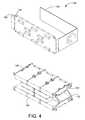
- FIG. 4is a partially exploded isometric view of a multiple disc array of the intelligent storage element of FIG. 3 .
- FIG. 5is an exemplary data storage device used in the multiple disc array of FIG. 4 .
- FIG. 6illustrates the general architecture of a selected one of the data storage arrays of FIG. 1 .
- FIG. 7provides a functional block diagram of a selected one of the controllers of FIG. 2 .
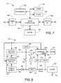
- FIG. 8illustrates relevant portions of one of the power modules of FIG. 6 constructed and operated in accordance with preferred embodiments of the present invention to supply operational and backup power to the cache memory of the controller of FIG. 2 .
- FIG. 9is a flowchart of steps in a method for CALIBRATION of a battery in accordance with illustrative embodiments of the present invention.
- FIG. 10provides voltage and current decay curves obtained during discharge of the battery during calibration.
- FIG. 11is a table of battery data stored in memory.
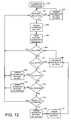
- FIG. 12is a flowchart of steps in a method of ARBITRATING CALIBRATION in accordance with embodiments of the present invention.
- FIG. 1is an illustrative computer system 100 in which embodiments of the present invention are useful.
- One or more hosts 102are networked to one or more network-attached servers 104 via a local area network (LAN) and/or wide area network (WAN) 106 .
- the LAN/WAN 106uses Internet protocol (IP) networking infrastructure for communicating over the World Wide Web.
- IPInternet protocol
- the hosts 102access applications resident in the servers 104 that routinely need data stored on one or more of a number of intelligent storage elements (“ISEs”) 108 .
- SANs 110connect the servers 104 to the ISEs 108 for access to the stored data.
- the ISEs 108provide blocks of data storage capacity 109 for storing the data over various selected communication protocols such as serial ATA and fibre-channel, with enterprise or desktop class storage medium within it.
- FIG. 2is a simplified diagrammatic view of a portion of the computer system 100 of FIG. 1 .
- the hosts 102interact with each other as well as with a pair of the ISEs 108 (denoted A and B, respectively) via the network or fabric 110 .
- Each ISE 108includes dual redundant controllers 112 (denoted A 1 , A 2 and B 1 , B 2 ) preferably operating on the data storage capacity 109 as a set of data storage devices characterized as a redundant array of independent drives (RAID).
- RAIDredundant array of independent drives
- the controllers 112 and data storage capacity 109preferably utilize a fault tolerant arrangement so that the various controllers 112 utilize parallel, redundant links and at least some of the user data stored by the system 100 is stored in redundant format within at least one set of the data storage capacities 109 .
- a host computer 102 and the A ISE 108can be physically located at a first site, the B host computer 102 and B ISE 108 can be physically located at a second site, and the C host computer 102 can be yet at a third site, although such is merely illustrative and not limiting. All entities on the distributed computer system are connected over some type of computer network.
- FIG. 3illustrates an ISE 108 constructed in accordance with embodiments of the present invention.
- a shelf 114defines cavities for receivingly engaging the controllers 112 in electrical connection with a midplane 116 .
- the shelf 114is supported, in turn, within a cabinet (not shown).
- a pair of multiple disc assemblies (MDAs) 118are receivingly engageable with the shelf 114 on the same side of the midplane 116 .
- Connected to the opposing side of the midplane 116are dual batteries 122 providing an emergency power supply, dual alternating current power supplies 124 , and dual interface modules 126 .
- the dual componentsare configured for operating either of the MDAs 118 or both simultaneously, thereby providing backup protection in the event of a component failure.
- FIG. 4is an enlarged partially exploded isometric view of an MDA 118 constructed in accordance with some embodiments of the present invention.
- the MDA 118has an upper partition 130 and a lower partition 132 , each supporting five data storage devices 128 .
- the partitions 130 , 132align the data storage devices 128 for connection with a common circuit board 134 having a connector 136 that operably engages the midplane 116 ( FIG. 3 ).
- a wrapper 138provides electromagnetic interference shielding.
- This illustrative embodiment of the MDA 118is the subject matter of patent application Ser. No. 10/884,605 entitled Carrier Device and Method for a Multiple Disc Array which is assigned to the assignee of the present invention and incorporated herein by reference.
- MDAis the subject matter of patent application Ser. No. 10/817,378 of the same title which is also assigned to the assignee of the present invention and incorporated herein by reference.
- the MDA 118can be provided within a sealed enclosure and holding an inert atmosphere.
- FIG. 5is an isometric view of an illustrative data storage device 128 suited for use with embodiments of the present invention and in the form of a rotating media disc drive.
- a rotating spindle with moving data storage mediumis used for discussion purposes below, in alternative equivalent embodiment a non-rotating medium device, such as a solid state memory device is used.
- a data storage disc 140is rotated by a motor 142 to present data storage locations of the disc 140 to a read/write head (“head”) 143 .
- the head 143is supported at the distal end of a rotary actuator 144 that is capable of moving the head 143 radially between inner and outer tracks of the disc 140 .
- the head 143is electrically connected to a circuit board 145 by way of a flex circuit 146 .
- the circuit board 145is adapted to receive and send control signals controlling the functions of the data storage device 128 .
- a connector 148is electrically connected to the circuit board 145 , and is adapted for connecting the data storage device 128 with the circuit board 134 ( FIG. 4 ) of the MDA 118 .
- each ISE 108includes the pair of controllers 112 (denoted A 1 /A 2 ) and the set of data storage devices 128 preferably characterized as hard disc drives operated as a RAID.
- the controllers 112 and devices 128preferably utilize a fault tolerant arrangement so that the various controllers 112 utilize parallel, redundant links and at least some of the user data stored by the system 100 is mirrored on both sets of devices 128 .
- Each ISE 108further includes the pair of power modules 122 (A 1 /A 2 ) which supply electrical power to the controllers 112 and the storage devices 128 .
- the power modules 122are preferably configured to operate in tandem so that during normal operation the power module A 1 supplies power to the controller A 1 and to half of the devices 128 , and the power module A 2 supplies power to the controller A 2 and to the other half of the devices 128 .
- Each power module 122is further sized and configured to be able to individually supply all of the power for the ISE 108 should the other power module 122 become inoperative or unavailable, such as for calibration purposes as described further below.
- FIG. 7provides a functional diagram of a selected one of the controllers 112 of FIG. 2 .
- a main processor 150uses programming and data stored in refreshed memory 152 (DRAM) and non-volatile memory (flash) 154 to provide top level control.
- a communication pathis provided by a fabric interface (I/F) block 156 , a path controller 158 and a device interface (I/F) block 160 .
- a refreshed cache memory device 162provides a memory space for the temporary storage of data being transferred between the host computers 102 and the storage devices 128 .
- the cache 162is preferably characterized as one or more DRAM modules having a total selected storage capacity (such as 1.024 gigabytes, GB).
- FIG. 8shows relevant portions of a selected one of the power modules 122 of FIG. 6 . It will be understood that FIG. 8 is generally directed to that portion of the module 122 that provides operational and standby (backup) power to the cache 162 .
- a power supply 190operates to receive input AC power from a domestic source (not shown) and output various associated DC voltages on different supply paths, such as the path 164 which is provided at nominally 12V.
- This voltageis supplied through protection diode 166 to a regulator 168 which applies voltage regulation to provide an output regulated voltage to path 170 .
- the regulated voltagepasses through a current sense resistor (RSENSE) 172 and then to the cache 162 .
- Ground connection 174denotes the completion of this main power supply loop.
- a pair of analog to digital converters 176 , 178are arranged on opposing sides of the sense resistor 172 as shown to provide digital indications of the voltage drop across the resistor to a control block 180 .
- the control block 180can comprise hardware or a software/firmware routine, as desired.
- a battery recharge circuit 182receives input voltage from the power supply via path 184 to selectively apply recharging current to a battery 186 (or other backup power source) via path 188 .
- the battery 186is configured to supply standby (backup) power to the cache 162 during an anomalous condition (i.e., failure of the power supply 190 ) to maintain the cache 162 in a continuous self-refresh mode, thereby allowing the cache 162 to save the then-existing contents stored therein until appropriate remedial corrective actions can be taken.
- the battery 186supplies an output voltage (such as on the order of 4-6 volts) on path 192 .
- path 192is preferably coupled to path 164 (i.e., switching element 194 is closed) so that the regulator receives power from both the power supply 190 and the battery 186 . This advantageously assures that should the power supply 190 be interrupted, power will continue to flow to the cache 162 .
- the switching element 194can comprise a suitable transistor, one or more protection diodes, etc., as desired.
- a third analog to digital converter 196(ADC 3 ) is coupled to the path 192 as shown, and provides a digital representation of the voltage on path 192 to the control block 180 .
- a shunt path 198also extends from the path 192 to provide a switching element 191 and a load (L) 193 .
- the circuitry of FIG. 8provides an apparatus with a plurality of batteries 186 that are individually selectable to provide power to the load 193 , and arbitration circuitry in the control 180 configured to selectively calibrate each of the batteries in relation to respective calibration status data stored in memory 195 for each of the batteries.
- the software controlled arbitration circuitry executed in the control 180can be configured to selectively calibrate the batteries 122 ( FIG. 3 ) in relation to a hierarchy of calibration statuses from a set consisting of a calibration done status (“CAL_DONE”), a calibration active status (“CAL_ACTIVE”), a calibration pending status (“CAL_PENDING”), a calibration failed status (“CAL_FAIL”), or possibly an internal state of unknown calibration.
- the arbitration circuitryrequires at least one battery having a CAL_DONE status before relinquishing another battery for calibration purposes.
- FIG. 8shows a temperature sensor (TEMP) 197 located in a suitable location to obtain ambient operational temperature readings and provide digital representations thereof to the control block 180 .
- TMPtemperature sensor
- FIG. 9provides a flow chart of steps for a battery power CALIBRATION routine 200 .
- the routine 200is preferably carried out at appropriate times during the operational life of the system 100 in order to assess the then-existing individual standby power capacity of each of the batteries 122 .
- an operational attributesometimes referred to more generally as an “operational attribute”
- a standardsometimes referred to more generally as a “predetermined fixed threshold”
- failure modescan be predicted and appropriate remedial actions taken preemptively to effectively maintain system availability at the requisite levels.
- the present embodimentscontemplate storing calibration records in non-volatile memory in order to retain a historical record indicative of tapering characteristics of the battery. For example, without limitation, as a battery ages its calibrated capacity decreases. Therefore, based on observing the trending data for calibrated capacity, a battery could be scheduled for replacement before it fails, and while it still has enough capacity to support the cache.
- the method 200begins at step 202 with the circuitry of FIG. 8 operating to charge the battery 186 to full capacity in a controlled manner, requiring an extended period of time (usually several hours).
- controlpasses to block 204 where the battery 186 is then discharged through the load 193 , again usually in a controlled manner over an extended period of time.
- the battery 186will generally not be available to supply standby power to the cache 162 ; however, as discussed above the preferred configuration of each ISE 108 provides redundant power modules 122 .
- Step 202thus further preferably comprises affirmatively arranging the battery backup capability of the other module 122 to cover for the cache 162 if such operation is not already an automatic feature of the system 100 .
- the battery recharging operation from circuit 182is temporarily suspended, the connection between path 192 and path 164 is broken (e.g., normally closed switching element 194 is opened), connection is made with the load 193 (e.g., normally open switching element 191 is closed), and the ADC 3 196 is configured to monitor the voltage from path 192 .
- the time required for a discharge of energy from the battery 186 to reach a preselected end-of-discharge (EOD) voltageis compared to a predetermined window of time. That is, during the controlled discharge the battery 186 is deemed to have passed calibration if the EOD voltage is reached after a predetermined lower threshold (t L ) time and before a predetermined upper threshold of time (t U ). Since the nominal impedance of the load 193 is known, the readings from the ADC 3 196 enable the control block 180 to generate voltage and current decay curves to show the characteristic decay in these levels during the energy discharge operation. Representative voltage and current decay curves are depicted at 203 and 205 in FIG. 10 .
- the controlled discharge of the battery 186 of step 204provides other benefits as well.
- the operational life of the rechargeable battery 186can be advantageously extended by the periodic full discharge of accumulated charge.
- the cache 162has a minimum voltage input level requirement in order to be able to successfully carry out the refresh operation.
- the energy available from the battery 186 at voltages below this valuei.e., to the right of broken line 207 in FIG. 10
- the data obtained during step 204thus further provides valuable information with regard to the tapering characteristics of the battery output, and allows an accurate assessment of the actual energy available to provide standby power to the cache 162 (i.e., those portions of the curves 203 , 205 to the left of line 207 ).
- block 206it is determined whether the EOD voltage was reached within the predetermined window between t L and t U . If the determination of block 206 is no, then control passes to block 208 where it is determined whether a retry of the failed calibration process is to be attempted. If so, then in block 210 a counter n (number of trials) is incremented, and control returns to block 202 . If the determination of block 208 is no, then in block 212 the status of the battery 186 is recorded in memory 195 as being CAL_FAIL and the software management layer is notified in block 213 .
- FIG. 11illustrates a sample charge record stored in memory 195 , wherein battery 1 is identified as having a status of CAL_FAIL, with a timestamp associated with when that status determination was made, and with calibrated capacity and calibration time data.
- the battery 186is subjected to another controlled charging process, which again can take an extended period of time during which the battery 186 remains unavailable to the system 100 .
- the load 193is disconnected from the battery 186 and the recharge circuit 182 is activated to begin recharging the battery 186 .
- the status of the battery 186is recorded in memory 195 as being CAL_DONE in block 216 .
- the routine 200is preferably configured to be performed automatically on an ongoing basis, as well as manually carried out by system administrator personnel at appropriate times as accessed through one of the hosts 102 .
- the resulting dataincluding actual measurements, curves and trends can likewise be reported via the hosts.
- FIG. 12is a flowchart showing illustrative steps of a method 250 for ARBITRATING CALIBRATION in accordance with embodiments of the present invention.
- the method 250is sequenced periodically for all batteries in the system, such as once every minute.
- the method 250functions as a hierarchical scrutiny of each battery 186 status in order to arbitrate which battery or batteries qualify as candidates for in-service duty and which one, if any, should be calibrated next.
- the health of all the batteries 186is checked.
- Batteries 186 that fail the health screenare assigned to non-service status in block 254 , and an alarm is preferably sent to the software management layer which can memorialize the alarm condition in an event log.
- Batteries 186 that pass the health screenform a pool from which an in-service battery 186 is assigned in block 256 .
- controlpasses to block 266 where it is determined whether any battery is reporting a CAL_FAILED status. If so, that battery is assigned to non-service duty and an alarm condition is triggered in block 268 as above. Control then passes to block 270 where it is determined whether any battery is reporting the CAL_PENDING status. Any battery not reporting CAL_PENDING at this stage of the hierarchical sequence is of an unknown status, such as would be the case of a new battery without any charge records yet. Such batteries are assigned to in-service duty and CAL_PENDING status in block 272 . Finally, in block 274 it is determined whether any of the batteries are ready to calibrate. If no, control returns to block 252 ; otherwise, another battery is assigned to in-service duty in block 276 and the designated battery is assigned to non-service duty in block 278 and then calibrated in block 264 .
- the present embodimentscontemplate a method (such as 250 ) for comparing charging records (such as 262 ) of each of a plurality of batteries (such as 186 ) that are alternatively selectable to provide power in a system, and instigating a battery power calibration procedure (such as 264 ) to the batteries in relation to results of the comparing step.
- the comparing stepis characterized by storing data associated with charging the batteries to memory (such as 195 ) to form the charging records, and subsequently retrieving the charging records from the memory.
- the charging records stored in memorycan include any useful information, such as a power calibration status and a time stamp associated with the power calibration status.
- the power calibration statuscan designate a done status, indicating a battery that has successfully been calibrated.
- a battery currently being calibratedcan indicate a power calibration status of active.
- a battery that has been identified as being in need of calibration, but not yet begun,can be identified as having a power calibration status of pending.
- a battery that has previously failed a calibration procedurecan have a power calibration status of failed.
- a battery statusis not identifiable by any of these categories then it is of an internal state best described as an unknown status.
- a new battery with no charge records, for example,would quickly be assigned a CAL_PENDING status to ensure it gets charged and calibrated as quickly as possible.
- the methoddetermines when a battery needs to be calibrated, and determines which battery to calibrate first when two or more need calibration. Preferably, the backup integrity of the system is maintained by not relinquishing a battery for calibration unless another battery is reporting a done status. If no battery exists reporting a done status, or if a battery fails the calibration sequence, then the method can signal an alarm to the management layer of the software and note the circumstances in an event log.
- the methodis carried out by an intelligent storage element (such as 108 ) in a distributed storage system.
- the present embodimentsalternatively characterized include an apparatus with a system load (such as 193 ) and a plurality of batteries that are individually selectable to provide power to the load, and software controlled arbitration circuitry (such as 180 ) configured to selectively calibrate each of the batteries in relation to the respective calibration status data stored in memory for each of the batteries.
- the arbitration circuitryis configured to selectively calibrate the batteries in relation to a hierarchy of the calibration statuses.
- a data storage systemis provided with an array of data storage devices (such as 108 ) operable via a selectable battery from a plurality of redundant batteries, and means for arbitrating power calibration of the batteries to maintain at least one battery in service to power the array at all times.
- the phrase “means for arbitrating”expressly requires circuitry as described herein that compares the present status of two or more batteries in order to arbitrate the calibration sequence when more than one battery is in need of the calibration. The comparison provides a multiple level hierarchical scheme for designating which battery to calibrate first among a plurality in need of calibration.
Landscapes
- Engineering & Computer Science (AREA)
- Power Engineering (AREA)
- Charge And Discharge Circuits For Batteries Or The Like (AREA)
Abstract
Description
Claims (20)
Priority Applications (1)
| Application Number | Priority Date | Filing Date | Title |
|---|---|---|---|
| US11/479,420US8519673B2 (en) | 2006-06-30 | 2006-06-30 | Arbitrating battery power calibration in a device that selects a battery power unit from a purality of selectable battery power units |
Applications Claiming Priority (1)
| Application Number | Priority Date | Filing Date | Title |
|---|---|---|---|
| US11/479,420US8519673B2 (en) | 2006-06-30 | 2006-06-30 | Arbitrating battery power calibration in a device that selects a battery power unit from a purality of selectable battery power units |
Publications (2)
| Publication Number | Publication Date |
|---|---|
| US20080007219A1 US20080007219A1 (en) | 2008-01-10 |
| US8519673B2true US8519673B2 (en) | 2013-08-27 |
Family
ID=38918549
Family Applications (1)
| Application Number | Title | Priority Date | Filing Date |
|---|---|---|---|
| US11/479,420Expired - Fee RelatedUS8519673B2 (en) | 2006-06-30 | 2006-06-30 | Arbitrating battery power calibration in a device that selects a battery power unit from a purality of selectable battery power units |
Country Status (1)
| Country | Link |
|---|---|
| US (1) | US8519673B2 (en) |
Cited By (2)
| Publication number | Priority date | Publication date | Assignee | Title |
|---|---|---|---|---|
| US9612956B2 (en) | 2013-03-15 | 2017-04-04 | Seagate Technology Llc | Multi-tiered caching for data storage management in a device |
| US10263455B2 (en) | 2016-06-17 | 2019-04-16 | L&B Solutions, LLC | Automated programmable battery balancing system and method of use |
Families Citing this family (12)
| Publication number | Priority date | Publication date | Assignee | Title |
|---|---|---|---|---|
| US7573154B2 (en)* | 2007-01-30 | 2009-08-11 | Perception Digital Limited | Battery operated portable electronic device having dual batteries |
| US8009502B2 (en)* | 2009-06-24 | 2011-08-30 | Seagate Technology Llc | Systems, methods and devices for power control in mass storage devices |
| US8230257B2 (en) | 2009-06-26 | 2012-07-24 | Seagate Technology Llc | Systems, methods and devices for controlling backup power provided to memory devices and used for storing of sensitive data |
| US8468379B2 (en)* | 2009-06-26 | 2013-06-18 | Seagate Technology Llc | Systems, methods and devices for control and generation of programming voltages for solid-state data memory devices |
| US8065562B2 (en)* | 2009-06-26 | 2011-11-22 | Seagate Technology Llc | Systems, methods and devices for backup power control in data storage devices |
| US8504860B2 (en)* | 2009-06-26 | 2013-08-06 | Seagate Technology Llc | Systems, methods and devices for configurable power control with storage devices |
| US8607076B2 (en)* | 2009-06-26 | 2013-12-10 | Seagate Technology Llc | Circuit apparatus with memory and power control responsive to circuit-based deterioration characteristics |
| US8479032B2 (en)* | 2009-06-26 | 2013-07-02 | Seagate Technology Llc | Systems, methods and devices for regulation or isolation of backup power in memory devices |
| US8031551B2 (en) | 2009-06-26 | 2011-10-04 | Seagate Technology Llc | Systems, methods and devices for monitoring capacitive elements in devices storing sensitive data |
| US8627117B2 (en)* | 2009-06-26 | 2014-01-07 | Seagate Technology Llc | Device with power control feature involving backup power reservoir circuit |
| US8468370B2 (en)* | 2009-09-16 | 2013-06-18 | Seagate Technology Llc | Systems, methods and devices for control of the operation of data storage devices using solid-state memory and monitoring energy used therein |
| US20180178366A1 (en)* | 2016-12-23 | 2018-06-28 | Andrei Matei | Modular tool system |
Citations (24)
| Publication number | Priority date | Publication date | Assignee | Title |
|---|---|---|---|---|
| US4151454A (en) | 1976-09-20 | 1979-04-24 | Kabushiki Kaisha Aichi Denkikosakusho | Remaining capacity detector of a battery |
| US4193026A (en) | 1976-04-18 | 1980-03-11 | Curtis Instruments, Inc. | Method and apparatus for measuring the state of charge of a battery by monitoring reductions in voltage |
| US4390841A (en) | 1980-10-14 | 1983-06-28 | Purdue Research Foundation | Monitoring apparatus and method for battery power supply |
| US5284719A (en) | 1992-07-08 | 1994-02-08 | Benchmarq Microelectronics, Inc. | Method and apparatus for monitoring battery capacity |
| US5717937A (en) | 1996-03-04 | 1998-02-10 | Compaq Computer Corporation | Circuit for selecting and designating a master battery pack in a computer system |
| US5838171A (en) | 1996-11-22 | 1998-11-17 | National Semiconductor Corporation | Low power real-time clock circuit having system and battery power arbitration |
| US5898880A (en) | 1996-03-13 | 1999-04-27 | Samsung Electronics Co., Ltd. | Power saving apparatus for hard disk drive and method of controlling the same |
| US5986435A (en) | 1982-06-07 | 1999-11-16 | Intermec Ip Corp. | Method of utilizing a battery powered system having two processors |
| US6043630A (en) | 1982-06-07 | 2000-03-28 | Intermec Ip Corp. | Fast battery charging system and method |
| US6104967A (en) | 1997-07-25 | 2000-08-15 | 3M Innovative Properties Company | Fault-tolerant battery system employing intra-battery network architecture |
| US6307349B1 (en) | 2000-02-24 | 2001-10-23 | Intermec Ip Corp. | Battery pack having memory |
| US6377028B1 (en) | 1990-10-23 | 2002-04-23 | Texas Instruments Incorporated | System for charging monitoring batteries for a microprocessor based method |
| US6463545B1 (en)* | 1999-10-01 | 2002-10-08 | Compaq Information Technologies Group, L.P. | Battery calibration system for discharging a rechargeable battery and generating an ac detect signal to power management logic to maintain normal computer operation even when battery is below certain level |
| US6529840B1 (en) | 1999-10-26 | 2003-03-04 | Cellon France | Device for estimating the state of charge of a battery |
| US6630814B2 (en) | 2000-12-19 | 2003-10-07 | Telefonaktiebolaget Lm Ericsson (Publ) | Method and apparatus for calibrating a rechargeable battery |
| US6642719B1 (en) | 2000-06-08 | 2003-11-04 | Mitsubishi Denki Kabushiki Kaisha | Device for judging life of auxiliary battery |
| US6704629B2 (en) | 2001-11-30 | 2004-03-09 | Bppower, Inc. | Device for monitoring motor vehicle's electric power and method therefor |
| US20040062119A1 (en) | 2002-09-26 | 2004-04-01 | Marc Stimak | Dynamic memory management |
| US6737831B2 (en) | 1999-09-01 | 2004-05-18 | Keith S. Champlin | Method and apparatus using a circuit model to evaluate cell/battery parameters |
| US20050138071A1 (en)* | 2003-12-18 | 2005-06-23 | International Business Machines Corporation | Accurate time information for the operation of an automated data storage library |
| US20050156603A1 (en) | 2003-04-02 | 2005-07-21 | Hsin-An Lin | Method of testing a battery pack by purposeful charge/discharge operations |
| US20050259460A1 (en)* | 2004-05-19 | 2005-11-24 | Masahiro Sone | Disk array device |
| US20070126400A1 (en)* | 2005-12-02 | 2007-06-07 | Southwest Electronic Energy Corporation | Battery pack control module |
| US20070190369A1 (en)* | 2006-02-14 | 2007-08-16 | Leach David H | Fuel cell based rechargable power pack system and associated methods for controlling same |
- 2006
- 2006-06-30USUS11/479,420patent/US8519673B2/ennot_activeExpired - Fee Related
Patent Citations (24)
| Publication number | Priority date | Publication date | Assignee | Title |
|---|---|---|---|---|
| US4193026A (en) | 1976-04-18 | 1980-03-11 | Curtis Instruments, Inc. | Method and apparatus for measuring the state of charge of a battery by monitoring reductions in voltage |
| US4151454A (en) | 1976-09-20 | 1979-04-24 | Kabushiki Kaisha Aichi Denkikosakusho | Remaining capacity detector of a battery |
| US4390841A (en) | 1980-10-14 | 1983-06-28 | Purdue Research Foundation | Monitoring apparatus and method for battery power supply |
| US5986435A (en) | 1982-06-07 | 1999-11-16 | Intermec Ip Corp. | Method of utilizing a battery powered system having two processors |
| US6043630A (en) | 1982-06-07 | 2000-03-28 | Intermec Ip Corp. | Fast battery charging system and method |
| US6377028B1 (en) | 1990-10-23 | 2002-04-23 | Texas Instruments Incorporated | System for charging monitoring batteries for a microprocessor based method |
| US5284719A (en) | 1992-07-08 | 1994-02-08 | Benchmarq Microelectronics, Inc. | Method and apparatus for monitoring battery capacity |
| US5717937A (en) | 1996-03-04 | 1998-02-10 | Compaq Computer Corporation | Circuit for selecting and designating a master battery pack in a computer system |
| US5898880A (en) | 1996-03-13 | 1999-04-27 | Samsung Electronics Co., Ltd. | Power saving apparatus for hard disk drive and method of controlling the same |
| US5838171A (en) | 1996-11-22 | 1998-11-17 | National Semiconductor Corporation | Low power real-time clock circuit having system and battery power arbitration |
| US6104967A (en) | 1997-07-25 | 2000-08-15 | 3M Innovative Properties Company | Fault-tolerant battery system employing intra-battery network architecture |
| US6737831B2 (en) | 1999-09-01 | 2004-05-18 | Keith S. Champlin | Method and apparatus using a circuit model to evaluate cell/battery parameters |
| US6463545B1 (en)* | 1999-10-01 | 2002-10-08 | Compaq Information Technologies Group, L.P. | Battery calibration system for discharging a rechargeable battery and generating an ac detect signal to power management logic to maintain normal computer operation even when battery is below certain level |
| US6529840B1 (en) | 1999-10-26 | 2003-03-04 | Cellon France | Device for estimating the state of charge of a battery |
| US6307349B1 (en) | 2000-02-24 | 2001-10-23 | Intermec Ip Corp. | Battery pack having memory |
| US6642719B1 (en) | 2000-06-08 | 2003-11-04 | Mitsubishi Denki Kabushiki Kaisha | Device for judging life of auxiliary battery |
| US6630814B2 (en) | 2000-12-19 | 2003-10-07 | Telefonaktiebolaget Lm Ericsson (Publ) | Method and apparatus for calibrating a rechargeable battery |
| US6704629B2 (en) | 2001-11-30 | 2004-03-09 | Bppower, Inc. | Device for monitoring motor vehicle's electric power and method therefor |
| US20040062119A1 (en) | 2002-09-26 | 2004-04-01 | Marc Stimak | Dynamic memory management |
| US20050156603A1 (en) | 2003-04-02 | 2005-07-21 | Hsin-An Lin | Method of testing a battery pack by purposeful charge/discharge operations |
| US20050138071A1 (en)* | 2003-12-18 | 2005-06-23 | International Business Machines Corporation | Accurate time information for the operation of an automated data storage library |
| US20050259460A1 (en)* | 2004-05-19 | 2005-11-24 | Masahiro Sone | Disk array device |
| US20070126400A1 (en)* | 2005-12-02 | 2007-06-07 | Southwest Electronic Energy Corporation | Battery pack control module |
| US20070190369A1 (en)* | 2006-02-14 | 2007-08-16 | Leach David H | Fuel cell based rechargable power pack system and associated methods for controlling same |
Cited By (4)
| Publication number | Priority date | Publication date | Assignee | Title |
|---|---|---|---|---|
| US9612956B2 (en) | 2013-03-15 | 2017-04-04 | Seagate Technology Llc | Multi-tiered caching for data storage management in a device |
| US10037277B2 (en) | 2013-03-15 | 2018-07-31 | Seagate Technology Llc | Multi-tiered caching for data storage management in a device |
| US10263455B2 (en) | 2016-06-17 | 2019-04-16 | L&B Solutions, LLC | Automated programmable battery balancing system and method of use |
| US10910872B2 (en) | 2016-06-17 | 2021-02-02 | L&B Solutions, LLC | Automated programmable battery balancing system and method of use |
Also Published As
| Publication number | Publication date |
|---|---|
| US20080007219A1 (en) | 2008-01-10 |
Similar Documents
| Publication | Publication Date | Title |
|---|---|---|
| US8519673B2 (en) | Arbitrating battery power calibration in a device that selects a battery power unit from a purality of selectable battery power units | |
| US6957355B2 (en) | Method and system for dynamically adjusting storage system write cache based on the backup battery level | |
| TWI677694B (en) | Intelligent backup capacitor management | |
| US8093868B2 (en) | In situ verification of capacitive power support | |
| USRE44009E1 (en) | Assessing energy requirements for a refreshed device | |
| US8031551B2 (en) | Systems, methods and devices for monitoring capacitive elements in devices storing sensitive data | |
| US8607076B2 (en) | Circuit apparatus with memory and power control responsive to circuit-based deterioration characteristics | |
| US6829724B2 (en) | Method for monitoring the condition of a battery in a high temperature high current environment | |
| US7721146B2 (en) | Method and system for bad block management in RAID arrays | |
| US8156381B2 (en) | Storage management apparatus and storage system | |
| US9639131B2 (en) | Systems, methods and devices for control of the operation of data storage devices using solid-state memory | |
| US7373559B2 (en) | Method and system for proactive drive replacement for high availability storage systems | |
| US7558988B2 (en) | Storage system and control method thereof | |
| JP5906966B2 (en) | Control device, power supply device, and power control method | |
| US8514565B2 (en) | Solid state storage device with removable power backup | |
| US7849261B2 (en) | Temperature control to reduce cascade failures in a multi-device array | |
| US20060212752A1 (en) | Method and apparatus for identifying a faulty component on a multiple component field replacement unit | |
| US20110072290A1 (en) | Auxiliary power supply, a method of providing power to a data storage system and a back-up power supply charging circuit | |
| JP2011509061A (en) | Improved battery state learning cycle apparatus and method | |
| TWI872193B (en) | Systems and methods for plp capacitor health check | |
| JP6515752B2 (en) | Storage control device, control method, and control program | |
| US7962776B2 (en) | Method and apparatus for detecting component removal while operating in a battery backup mode | |
| US8375249B1 (en) | Method for testing battery backup units | |
| US20200264946A1 (en) | Failure sign detection device, failure sign detection method, and recording medium in which failure sign detection program is stored | |
| US11360531B1 (en) | Redeployment of energy storage units |
Legal Events
| Date | Code | Title | Description |
|---|---|---|---|
| AS | Assignment | Owner name:SEAGATE TECHNOLOGY LLC, CALIFORNIA Free format text:ASSIGNMENT OF ASSIGNORS INTEREST;ASSIGNOR:WILLIAMS, JEFFREY A.;REEL/FRAME:018071/0785 Effective date:20060630 | |
| AS | Assignment | Owner name:WELLS FARGO BANK, NATIONAL ASSOCIATION, AS COLLATERAL AGENT AND SECOND PRIORITY REPRESENTATIVE, CALIFORNIA Free format text:SECURITY AGREEMENT;ASSIGNORS:MAXTOR CORPORATION;SEAGATE TECHNOLOGY LLC;SEAGATE TECHNOLOGY INTERNATIONAL;REEL/FRAME:022757/0017 Effective date:20090507 Owner name:JPMORGAN CHASE BANK, N.A., AS ADMINISTRATIVE AGENT AND FIRST PRIORITY REPRESENTATIVE, NEW YORK Free format text:SECURITY AGREEMENT;ASSIGNORS:MAXTOR CORPORATION;SEAGATE TECHNOLOGY LLC;SEAGATE TECHNOLOGY INTERNATIONAL;REEL/FRAME:022757/0017 Effective date:20090507 Owner name:JPMORGAN CHASE BANK, N.A., AS ADMINISTRATIVE AGENT Free format text:SECURITY AGREEMENT;ASSIGNORS:MAXTOR CORPORATION;SEAGATE TECHNOLOGY LLC;SEAGATE TECHNOLOGY INTERNATIONAL;REEL/FRAME:022757/0017 Effective date:20090507 Owner name:WELLS FARGO BANK, NATIONAL ASSOCIATION, AS COLLATE Free format text:SECURITY AGREEMENT;ASSIGNORS:MAXTOR CORPORATION;SEAGATE TECHNOLOGY LLC;SEAGATE TECHNOLOGY INTERNATIONAL;REEL/FRAME:022757/0017 Effective date:20090507 | |
| AS | Assignment | Owner name:MAXTOR CORPORATION, CALIFORNIA Free format text:RELEASE;ASSIGNOR:JPMORGAN CHASE BANK, N.A., AS ADMINISTRATIVE AGENT;REEL/FRAME:025662/0001 Effective date:20110114 Owner name:SEAGATE TECHNOLOGY INTERNATIONAL, CALIFORNIA Free format text:RELEASE;ASSIGNOR:JPMORGAN CHASE BANK, N.A., AS ADMINISTRATIVE AGENT;REEL/FRAME:025662/0001 Effective date:20110114 Owner name:SEAGATE TECHNOLOGY LLC, CALIFORNIA Free format text:RELEASE;ASSIGNOR:JPMORGAN CHASE BANK, N.A., AS ADMINISTRATIVE AGENT;REEL/FRAME:025662/0001 Effective date:20110114 Owner name:SEAGATE TECHNOLOGY HDD HOLDINGS, CALIFORNIA Free format text:RELEASE;ASSIGNOR:JPMORGAN CHASE BANK, N.A., AS ADMINISTRATIVE AGENT;REEL/FRAME:025662/0001 Effective date:20110114 | |
| AS | Assignment | Owner name:THE BANK OF NOVA SCOTIA, AS ADMINISTRATIVE AGENT, CANADA Free format text:SECURITY AGREEMENT;ASSIGNOR:SEAGATE TECHNOLOGY LLC;REEL/FRAME:026010/0350 Effective date:20110118 Owner name:THE BANK OF NOVA SCOTIA, AS ADMINISTRATIVE AGENT, Free format text:SECURITY AGREEMENT;ASSIGNOR:SEAGATE TECHNOLOGY LLC;REEL/FRAME:026010/0350 Effective date:20110118 | |
| AS | Assignment | Owner name:EVAULT INC. (F/K/A I365 INC.), CALIFORNIA Free format text:TERMINATION AND RELEASE OF SECURITY INTEREST IN PATENT RIGHTS;ASSIGNOR:WELLS FARGO BANK, NATIONAL ASSOCIATION, AS COLLATERAL AGENT AND SECOND PRIORITY REPRESENTATIVE;REEL/FRAME:030833/0001 Effective date:20130312 Owner name:SEAGATE TECHNOLOGY LLC, CALIFORNIA Free format text:TERMINATION AND RELEASE OF SECURITY INTEREST IN PATENT RIGHTS;ASSIGNOR:WELLS FARGO BANK, NATIONAL ASSOCIATION, AS COLLATERAL AGENT AND SECOND PRIORITY REPRESENTATIVE;REEL/FRAME:030833/0001 Effective date:20130312 Owner name:SEAGATE TECHNOLOGY INTERNATIONAL, CAYMAN ISLANDS Free format text:TERMINATION AND RELEASE OF SECURITY INTEREST IN PATENT RIGHTS;ASSIGNOR:WELLS FARGO BANK, NATIONAL ASSOCIATION, AS COLLATERAL AGENT AND SECOND PRIORITY REPRESENTATIVE;REEL/FRAME:030833/0001 Effective date:20130312 Owner name:SEAGATE TECHNOLOGY US HOLDINGS, INC., CALIFORNIA Free format text:TERMINATION AND RELEASE OF SECURITY INTEREST IN PATENT RIGHTS;ASSIGNOR:WELLS FARGO BANK, NATIONAL ASSOCIATION, AS COLLATERAL AGENT AND SECOND PRIORITY REPRESENTATIVE;REEL/FRAME:030833/0001 Effective date:20130312 | |
| STCF | Information on status: patent grant | Free format text:PATENTED CASE | |
| FPAY | Fee payment | Year of fee payment:4 | |
| FEPP | Fee payment procedure | Free format text:MAINTENANCE FEE REMINDER MAILED (ORIGINAL EVENT CODE: REM.); ENTITY STATUS OF PATENT OWNER: LARGE ENTITY | |
| LAPS | Lapse for failure to pay maintenance fees | Free format text:PATENT EXPIRED FOR FAILURE TO PAY MAINTENANCE FEES (ORIGINAL EVENT CODE: EXP.); ENTITY STATUS OF PATENT OWNER: LARGE ENTITY | |
| STCH | Information on status: patent discontinuation | Free format text:PATENT EXPIRED DUE TO NONPAYMENT OF MAINTENANCE FEES UNDER 37 CFR 1.362 | |
| FP | Lapsed due to failure to pay maintenance fee | Effective date:20210827 | |
| AS | Assignment | Owner name:SEAGATE TECHNOLOGY PUBLIC LIMITED COMPANY, CALIFORNIA Free format text:RELEASE BY SECURED PARTY;ASSIGNOR:THE BANK OF NOVA SCOTIA;REEL/FRAME:072193/0001 Effective date:20250303 Owner name:SEAGATE TECHNOLOGY, CALIFORNIA Free format text:RELEASE BY SECURED PARTY;ASSIGNOR:THE BANK OF NOVA SCOTIA;REEL/FRAME:072193/0001 Effective date:20250303 Owner name:SEAGATE TECHNOLOGY HDD HOLDINGS, CALIFORNIA Free format text:RELEASE BY SECURED PARTY;ASSIGNOR:THE BANK OF NOVA SCOTIA;REEL/FRAME:072193/0001 Effective date:20250303 Owner name:I365 INC., CALIFORNIA Free format text:RELEASE BY SECURED PARTY;ASSIGNOR:THE BANK OF NOVA SCOTIA;REEL/FRAME:072193/0001 Effective date:20250303 Owner name:SEAGATE TECHNOLOGY LLC, CALIFORNIA Free format text:RELEASE BY SECURED PARTY;ASSIGNOR:THE BANK OF NOVA SCOTIA;REEL/FRAME:072193/0001 Effective date:20250303 Owner name:SEAGATE TECHNOLOGY INTERNATIONAL, CAYMAN ISLANDS Free format text:RELEASE BY SECURED PARTY;ASSIGNOR:THE BANK OF NOVA SCOTIA;REEL/FRAME:072193/0001 Effective date:20250303 Owner name:SEAGATE HDD CAYMAN, CAYMAN ISLANDS Free format text:RELEASE BY SECURED PARTY;ASSIGNOR:THE BANK OF NOVA SCOTIA;REEL/FRAME:072193/0001 Effective date:20250303 Owner name:SEAGATE TECHNOLOGY (US) HOLDINGS, INC., CALIFORNIA Free format text:RELEASE BY SECURED PARTY;ASSIGNOR:THE BANK OF NOVA SCOTIA;REEL/FRAME:072193/0001 Effective date:20250303 |