US8519581B2 - Electric machine cooling system and method - Google Patents
Electric machine cooling system and methodDownload PDFInfo
- Publication number
- US8519581B2 US8519581B2US12/796,563US79656310AUS8519581B2US 8519581 B2US8519581 B2US 8519581B2US 79656310 AUS79656310 AUS 79656310AUS 8519581 B2US8519581 B2US 8519581B2
- Authority
- US
- United States
- Prior art keywords
- electric machine
- coolant
- rotor
- agitator member
- agitator
- Prior art date
- Legal status (The legal status is an assumption and is not a legal conclusion. Google has not performed a legal analysis and makes no representation as to the accuracy of the status listed.)
- Active, expires
Links
Images


Classifications
- H—ELECTRICITY
- H02—GENERATION; CONVERSION OR DISTRIBUTION OF ELECTRIC POWER
- H02K—DYNAMO-ELECTRIC MACHINES
- H02K9/00—Arrangements for cooling or ventilating
- H02K9/19—Arrangements for cooling or ventilating for machines with closed casing and closed-circuit cooling using a liquid cooling medium, e.g. oil
- H—ELECTRICITY
- H02—GENERATION; CONVERSION OR DISTRIBUTION OF ELECTRIC POWER
- H02K—DYNAMO-ELECTRIC MACHINES
- H02K1/00—Details of the magnetic circuit
- H02K1/06—Details of the magnetic circuit characterised by the shape, form or construction
- H02K1/12—Stationary parts of the magnetic circuit
- H02K1/20—Stationary parts of the magnetic circuit with channels or ducts for flow of cooling medium
- H—ELECTRICITY
- H02—GENERATION; CONVERSION OR DISTRIBUTION OF ELECTRIC POWER
- H02K—DYNAMO-ELECTRIC MACHINES
- H02K1/00—Details of the magnetic circuit
- H02K1/06—Details of the magnetic circuit characterised by the shape, form or construction
- H02K1/22—Rotating parts of the magnetic circuit
- H02K1/28—Means for mounting or fastening rotating magnetic parts on to, or to, the rotor structures
- H02K1/30—Means for mounting or fastening rotating magnetic parts on to, or to, the rotor structures using intermediate parts, e.g. spiders
- H—ELECTRICITY
- H02—GENERATION; CONVERSION OR DISTRIBUTION OF ELECTRIC POWER
- H02K—DYNAMO-ELECTRIC MACHINES
- H02K1/00—Details of the magnetic circuit
- H02K1/06—Details of the magnetic circuit characterised by the shape, form or construction
- H02K1/22—Rotating parts of the magnetic circuit
- H02K1/32—Rotating parts of the magnetic circuit with channels or ducts for flow of cooling medium
- H—ELECTRICITY
- H02—GENERATION; CONVERSION OR DISTRIBUTION OF ELECTRIC POWER
- H02K—DYNAMO-ELECTRIC MACHINES
- H02K15/00—Processes or apparatus specially adapted for manufacturing, assembling, maintaining or repairing of dynamo-electric machines
- H02K15/16—Centring rotors within the stators
- H02K15/165—Balancing the rotors
- H—ELECTRICITY
- H02—GENERATION; CONVERSION OR DISTRIBUTION OF ELECTRIC POWER
- H02K—DYNAMO-ELECTRIC MACHINES
- H02K5/00—Casings; Enclosures; Supports
- H02K5/04—Casings or enclosures characterised by the shape, form or construction thereof
- H02K5/20—Casings or enclosures characterised by the shape, form or construction thereof with channels or ducts for flow of cooling medium
- H02K5/203—Casings or enclosures characterised by the shape, form or construction thereof with channels or ducts for flow of cooling medium specially adapted for liquids, e.g. cooling jackets
- B—PERFORMING OPERATIONS; TRANSPORTING
- B60—VEHICLES IN GENERAL
- B60K—ARRANGEMENT OR MOUNTING OF PROPULSION UNITS OR OF TRANSMISSIONS IN VEHICLES; ARRANGEMENT OR MOUNTING OF PLURAL DIVERSE PRIME-MOVERS IN VEHICLES; AUXILIARY DRIVES FOR VEHICLES; INSTRUMENTATION OR DASHBOARDS FOR VEHICLES; ARRANGEMENTS IN CONNECTION WITH COOLING, AIR INTAKE, GAS EXHAUST OR FUEL SUPPLY OF PROPULSION UNITS IN VEHICLES
- B60K1/00—Arrangement or mounting of electrical propulsion units
- B60K2001/003—Arrangement or mounting of electrical propulsion units with means for cooling the electrical propulsion units
- B60K2001/006—Arrangement or mounting of electrical propulsion units with means for cooling the electrical propulsion units the electric motors
- B—PERFORMING OPERATIONS; TRANSPORTING
- B60—VEHICLES IN GENERAL
- B60Y—INDEXING SCHEME RELATING TO ASPECTS CROSS-CUTTING VEHICLE TECHNOLOGY
- B60Y2200/00—Type of vehicle
- B60Y2200/90—Vehicles comprising electric prime movers
- B60Y2200/92—Hybrid vehicles
- Y—GENERAL TAGGING OF NEW TECHNOLOGICAL DEVELOPMENTS; GENERAL TAGGING OF CROSS-SECTIONAL TECHNOLOGIES SPANNING OVER SEVERAL SECTIONS OF THE IPC; TECHNICAL SUBJECTS COVERED BY FORMER USPC CROSS-REFERENCE ART COLLECTIONS [XRACs] AND DIGESTS
- Y02—TECHNOLOGIES OR APPLICATIONS FOR MITIGATION OR ADAPTATION AGAINST CLIMATE CHANGE
- Y02T—CLIMATE CHANGE MITIGATION TECHNOLOGIES RELATED TO TRANSPORTATION
- Y02T10/00—Road transport of goods or passengers
- Y02T10/60—Other road transportation technologies with climate change mitigation effect
- Y02T10/62—Hybrid vehicles
Definitions
- Hybrid vehiclesoffer an opportunity for vehicle drivers to engage in environmentally-conscious behavior because of hybrids' improved fuel economy and reduced emissions.
- Hybrid vehiclescombine traditional internal combustion engines with an electro-mechanical transmission. Electric motors located within the electro-mechanical transmission provide energy to propel the vehicle, reducing the need for energy provided by the internal combustion engine, thereby increasing fuel economy and reducing emissions.
- the hybrid transmission's electric motorrejects some energy in the form of heat. Efficient removal of heat from the electric motor can improve the lifespan of the electric machine as well as improve the electric machine's operating efficiency.
- the electric machine modulecan include an electric machine including a rotor with generally opposing end faces and a stator with stator end turns.
- the electric machine modulecan also include an agitator member operatively coupled to the rotor adjacent the generally opposing end faces and extending substantially outward along at least a portion of an axial length of the stator end turns.
- Some embodiments of the inventionprovide a method for cooling an electric machine.
- the methodcan include providing the electric machine including a rotor with generally opposing end faces and a stator substantially circumscribing the rotor and including stator end turns.
- the methodcan also include substantially enclosing at least a portion of the electric machine within a housing and defining at least a portion of a machine cavity with an inner wall of the housing.
- the methodcan further include introducing a coolant into the machine cavity, directing the coolant toward the stator end turns, and returning a portion of the coolant which flows past the stator end turns back toward the stator end turns for cooling using a rotating agitator member operatively coupled to the rotor near the generally opposing end faces.
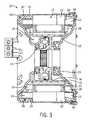
- FIG. 1is a cross-sectional view of an electric machine module according to one embodiment of the invention.
- FIG. 2is a partial cross-sectional view of an electric machine with an agitator member, according to one embodiment of the invention.
- FIG. 3is another cross-sectional view of the electric machine module according to one embodiment of the invention.
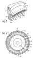
- FIG. 4is a perspective view of a portion of the electric machine of FIG. 2 .
- FIG. 5is a partial perspective view of a portion of the electric machine of FIG. 2 .
- FIG. 6is a cross-sectional view of the electric machine of FIG. 2 .
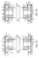
- FIG. 7Ais a cross-sectional view of an electric machine module according to another embodiment of the invention.
- FIG. 7Bis a cross-sectional view of an electric machine module according to yet another embodiment of the invention.
- FIG. 1illustrates an electric machine module 10 according to one embodiment of the invention.
- the machine module 10can include an electric machine 12 and a housing 14 .
- the electric machine 12can be disposed within a machine cavity 16 defined at least partially by an inner wall 18 of the housing 14 .
- the electric machine 12can include a rotor 20 , a stator 22 substantially circumscribing the rotor 20 , stator end turns 24 , and bearings 26 , and can be disposed about a main output shaft 28 .
- the electric machine 12can also include a rotor hub 30 or can have a “hub-less” design (not shown).
- the electric machine 12can be, without limitation, an electric motor, such as a hybrid electric motor, an electric generator, or a vehicle alternator.
- the electric machine 12can be an induction belt-alternator-starter (BAS).
- the electric machine 12can be a High Voltage Hairpin (HVH) electric motor for use in a hybrid vehicle.
- HVHHigh Voltage Hairpin
- Components of the electric machine 12such as, but not limited to, the stator end turns 24 , the rotor 20 , and the rotor hub 30 can generate heat during operation of the electric machine 12 . These components can be cooled to enhance the performance of and increase the lifespan of the electric machine 12 .
- the rotor 20can include generally opposing end faces 32 , 34 .
- a balance ring 36can be coupled to the rotor 20 and/or the rotor hub 30 at a location proximal to the generally opposing end faces 32 , 34 .
- the balance ring 36can be coupled to the rotor hub 30 using threads, a plurality of threaded fasteners, a friction fitting, welding, or another conventional coupling manner so that the balance ring 36 can rotate substantially synchronously with the rotor 20 and the rotor hub 30 during operation of the electric motor 12 .
- the balance ring 36can be “staked” to a lip 35 on an inner diameter of the rotor hub 30 and a portion of the balance ring 36 can be heat pressed to a lamination stack of the rotor 20 (e.g., for axial support), as shown in FIG. 3 . Additional components, such as steel insert pieces, can also be used to help clamp the balance ring 36 to the rotor hub 30 around the lip 35 .
- the balance ring 36can extend axially from the rotor hub 30 into the machine cavity 16 and can provide stability for the rotor 20 and rotor hub 30 during operation of the electric machine 12 .
- the balance ring 36comprises cast aluminum.
- the balance ring 36can be coupled to the rotor 20 proximal to the generally opposing end faces 32 , 34 , as shown in FIG. 2 .
- the balance ring 36can be coupled to the rotor 20 using threads, a plurality of threaded fasteners, a friction fitting, welding, or another conventional coupling manner so that the balance ring 36 can rotate substantially synchronously with the rotor 20 during operation of the electric motor 12 .
- the balance ring 36can provide stability for the rotor 20 during operation of the electric machine 12 .
- the balance ring 36can be operatively coupled to the rotor 20 (i.e., through direct coupling or coupling via the rotor hub 30 ) due to the fact that it can rotate with the rotor 20 during operation of the electric machine.
- an agitator member 38can be a ring-shaped member coupled to the rotor 20 , the rotor hub 30 , and/or the balance ring 36 proximal to the generally opposing end faces 32 , 34 . More specifically, at least a portion of the agitator member 38 can be coupled to the rotor 20 , the rotor hub 30 and/or the balance ring 36 such that the agitator member 38 synchronously rotates with the rotor 20 and the rotor hub 30 when the electric machine 12 is in operation.
- the agitator member 38can be coupled to the rotor 20 , the rotor hub 30 , and/or the balance ring 36 using threads, one or more threaded fasteners, a friction fitting, welding, or another conventional coupling manner.
- the agitator member 38can be staked to a lip (not shown) on the inner diameter of the rotor hub 20 and further axial support can be provided by heat pressing a portion of the agitator member 34 in a lamination stack surrounding the rotor 20 .
- the agitator member 38can be cast as part of the rotor 20 during rotor fabrication so that the agitator member 38 and the rotor 20 are integral.
- the agitator member 38can be integral with the balance ring 36 .
- the agitator member 38can extend axially away from the rotor 20 and/or the rotor hub 30 into the machine cavity 16 .
- the agitator member 38can be coupled to the rotor 20 and/or the rotor hub 30 with or without the balance ring 36 . If the balance ring 36 is present, an axial length of the agitator member 38 can be substantially equal to or longer than an axial length of the balance ring 36 . For example, in one embodiment, at least a portion of the agitator member 38 can extend axially past the balance ring 36 (i.e., axially away from the rotor 20 ). In addition, the agitator member 38 can extend substantially parallel to the stator end turns 24 along at least a portion of an axial length of the stator end turns 24 .
- the agitator member 38can extend substantially axially outward about as far as the stator end turns 24 . In other embodiments, the axial length of the agitator member 38 can be shorter than or longer than the axial length of the stator end turns 24 .
- the agitator member 38can be operatively coupled to the rotor 20 (i.e., through direct coupling or coupling via the rotor hub 30 or the balance ring 36 ) due to the fact that it can rotate with the rotor 20 during operation of the electric machine.
- the agitator member 38 and the balance ring 36can be an integral structure, as described above. In other embodiments, the balance ring 36 and the agitator member 38 can comprise two or more independent components.
- the balance ring 36 and the agitator member 38can be fabricated from aluminum, steel, stainless steel, or other similar materials.
- the agitator member 38can be oriented so that it extends substantially parallel to an axis of rotation 40 of the rotor 20 . In other embodiments, the agitator member 38 can be oriented in either a positive or negative direction relative to the rotor's axis of rotation 40 .
- the agitator member 38can include a radially distal surface 42 and a radially proximal surface 44 .
- the radial location of a both the radially distal surface 42 and the radially proximal surface 44can vary.
- the radially distal surface 42can have a shorter radius than the rotor 20 (e.g., by a length “x”, as shown in FIG. 4 ) or can have a radius equal to a radius of the rotor 20 (as shown in FIG. 2 ).
- the radially distal surface 42can have a shorter radius than the radius of the rotor 20 to provide substantial radial separation between an underside of the stator end turns 24 and the agitator member 38 .
- a plurality of struts 46can provide support for the agitator member 38 .
- the plurality of struts 46can be cast or otherwise formed in the agitator member 38 so that the struts 46 and the agitator member 38 are a unitary body.
- the housing 14can include a plurality of coolant apertures 48 .
- the coolant apertures 48can be in fluid communication with, for example, a coolant jacket 50 located substantially around the electric machine 12 (e.g., within an inner wall of the housing 14 or along the outside or inside of the housing 14 substantially surrounding an outer diameter of the stator 22 ) and the machine cavity 16 .
- a coolantsuch as transmission fluid, ethylene glycol, an ethylene glycol/water mixture, water, oil, or a similar substance, can originate from a fluid source (not shown), flow throughout the coolant jacket 50 , and can be dispersed through the coolant apertures 48 into the machine cavity 16 .
- the coolant apertures 48can be positioned so that the coolant can be dispersed onto the stator end turns 24 , as shown in FIG. 2 . After reaching the stator end turns 24 , the coolant can receive heat energy from the stator end turns 24 , which can result in cooling of the electric machine 12 . Some of the coolant can be dispersed past the stator end turns 24 or, for example, splash or drip from the stator end turns 24 onto the radially distal surface 42 of the agitator member 38 . In addition, some of the coolant that comes in contact with the stator end turns 24 can continue to flow toward the radially distal surface 42 .
- the coolantcan be substantially radially slung back outward on to the stator end turns 24 due to the rotation of the agitator member 38 in synchronicity with the rotor 20 .
- the process of radially slinging the coolant toward the stator end turns 24can serve to recycle the coolant, and thus, maximize cooling potential of the coolant.
- the process of radially slinging the coolant back toward the stator end turns 24 using the agitator member 38can be considered a “multiple-pass” method of cooling, as the coolant can reach the stator end turns 24 multiple times to provide additional cooling.
- Conventional electric machinesuse a “single-pass” method of cooling where the coolant only reaches the stator end turns 24 once and then is discharged away from the electric machine 12 without further cooling benefits.
- the single-pass methodonly permits the coolant to reach radially outer surfaces of the stator ends turns 24
- the multiple-pass methodallows coolant to be slung back towards radially inner surfaces of the stator end turns 24 .
- the multiple-pass cooling methodallows the coolant to reach both the radially outer surface as well as the radially inner surface of the stator end turns 24 , and thus, provides enhanced cooling.
- the radially distal surface 42can include a textured surface 52 .
- the textured surface 52can have different textures such as scalloping, ribbing, ridging, etc.
- the textured surface 52can be asymmetric in shape to increase the force with which the coolant is slung.
- the radially distal surface 42can lack texture and can include a substantially planar or smooth surface.
- the agitator member 38can enhance radial slinging of the coolant because it provides more surface area to receive the coolant. Also, because the agitator member 34 can synchronously rotate with the rotor 20 and/or the rotor hub 30 , centrifugal force can force the coolant away from the agitator member 38 so that the coolant can be dispersed onto the stator end turns 24 . In one embodiment, the amount and shape of texturing on the textured surface 52 can be selected to provide a desired amount of cooling without slinging the coolant at velocities which can possibly erode the stator end turns 24 .
- the agitator member 38can further increase air circulation within the machine cavity 16 , and thus, enhance electric machine cooling, because its larger mass, relative to a balance ring alone, can displace more air when the agitator member 38 is in motion.
- the textured surface 52can be shaped similar to pump or fan vanes to help increase air circulation and/or increase radial slinging of the coolant.
- the agitator member 38can include a plurality of agitator channels 54 . As shown in FIGS. 2 and 5 , the agitator channels 54 can extend radially through the agitator member 38 . The plurality of agitator channels 54 can extend through any desired radial length of the agitator member 38 , such as a full length of the agitator member 34 or a portion of the full length of the agitator member 38 . The agitator channels 54 can be positioned at nearly any distance along the axial length of the agitator member 38 (e.g., more proximal to the rotor 20 , centrally along the axial length, or more distal from the rotor 20 ). For example, as shown in FIG.
- the plurality of agitator channels 54can be positioned axially distal from the rotor 20 .
- the location of each of the plurality of agitator channels 54can be symmetric or asymmetric along the agitator member 38 (i.e., not each agitator channel may be positioned at the same distance along the axial length of the agitator member 38 ).
- any number of agitator channels 54can be included in the agitator member 38 , or in attachments to the agitator member 38 .
- each of the plurality of agitator channels 54can be circular in shape.
- the agitator channels 54can have similar or different shapes, including circular, square, rectangle, oval, and/or other shapes.
- the plurality of agitator channels 54can include similar or varying radii or diameters.
- the agitator channels 54can be of sufficient size to allow passage of a portion of the coolant through the agitator channels 54 , as described below.
- the agitator channels 54can be sized and positioned so that another portion of the coolant that reaches the agitator member 38 can continue to be substantially radially slung toward the stator end turns 24 .
- an additional volume of the coolantalso can be expelled near the rotor hub 30 , for example, from a base of the rotor hub 30 or from the main input shaft 28 .
- the coolant expelled near the rotor hub 30can flow radially outward toward the housing 12 (e.g., due to centrifugal force).
- a portion of the coolantcan reach the radially proximal surface 44 of the agitator member 38 , and the agitator channels 54 can provide a pathway for the coolant to flow between the radially proximal surface and the radially distal surface.
- the coolant 50 flowing radially outward onto the agitator member 38can flow through the agitator channels 54 so that it reaches the radially distal surface 42 and is substantially radially slung toward the stator end turns 24 , or at least concentrated near the stator end turns 24 .
- the additional volume of coolantcan further aid in cooling the electric machine 12 , including the stator end turns 24 .
- FIGS. 7A and 7Billustrate the electric machine module 10 according to another embodiment of the invention.
- a cover 56can be coupled to the inner wall 18 and at least partially surround the stator end turns 24 so that the cover 56 and each of the stator end turns 24 define a stator cavity 58 around the stator end turns 24 .
- the stator cavity 58can be in fluid communication with the machine cavity 16 .
- the cover 56can also substantially surround the stator 22 .
- FIG. 7Aillustrates the cover entirely surrounding the stator 22 as well as partially surrounding the stator end turns 24 (e.g., as an integral stator housing ring and cover assembly).
- additional caps(not shown) can enclose the cover 56 within the housing 14 .
- the cover 56can be a part of the housing 14 (e.g., extending from the inner wall 18 on either end of the stator 22 to partially surround the stator end turns 24 ).
- the cover 56can extend a desired radial distance from the inner wall 18 and, in some embodiments, can turn back inward axially, as shown in FIGS. 7A and 7B .
- the cover 56can also be positioned a desired axial distance from the housing 14 .
- the desired distancescan be uniform or vary along radial portions of, or along the circumference of, the electric machine 12 and, as a result, the stator cavity 58 can be uniform or vary in size along the radial portions.
- the stator cavity 58may not extend around the entire 360 degrees of the stator end turns 24 (i.e., some radial portions of the stator end turns 24 are not surrounded by the cover 56 ).
- the cover 56can comprise plastic, aluminum, steel, a polymeric material, or a similar material.
- the size of the stator cavity 58can vary depending on the dielectric properties of the coolant and the materials from which the cover 56 are fabricated or depending on its radial position within the electric machine module 10 .
- the size of the stator cavity 58can be reduced by coating an area of the cover 56 closest to the stator end turns 24 with a material of high dielectric strength, such as an epoxy material 60 , as shown in FIG. 3 .
- an upper portion of the electric machine module 10can include a substantially larger stator cavity 58 than a lower portion of the electric machine module 10 .
- the cover 56can be coupled to the inner wall 18 by press fitting, friction fitting, threaded fasteners, or a similar coupling manner.
- the cover 56can comprise one or more parts, where some parts of the cover 56 are integral with the inner wall 18 and other parts of the cover are coupled to the inner wall 18 .
- the stator cavity 58can receive the coolant from the cooling jacket 50 and the coolant apertures 48 (similar to that shown in FIG. 2 ), or from a cooling jacket 59 formed between the cover 56 and the inner wall 18 through coolant apertures 61 of the cover 56 .
- the cooling jacket 59can receive the coolant from a feed port 62 , as shown in FIGS. 6-7B , in fluid communication with the fluid source.
- the cover 56can help concentrate the flowing coolant within the stator cavity 52 so that the coolant can remain in contact with or near the stator end turns 24 for a prolonged time period in order to help transfer more heat energy.
- the coolantcan eventually disperse out of the stator cavity 58 toward the machine cavity 16 .
- the cover 56can greatly enhance cooling of the stator end turns 24 because the cover 56 can prevent at least some of the coolant from quickly dispersing away from the stator end turns 24 and can help concentrate the coolant near the heat energy-radiating stator end turns 24 .
- the stator cavity 58can be defined by the cover 56 and the stator end turns 24 as well as the agitator member 38 .
- the stator cavity 58can be in fluid communication with the machine cavity 16 , as described above.
- the coolantenters the stator cavity 58
- the coolantcan flow onto the stator end turns 24 and can be concentrated within the stator cavity 58 by the presence of the cover 56 .
- the coolantflows toward the agitator member 38 , it can be radially slung back toward the stator end turns 24 and the cover 56 where it can once again become concentrated around the stator end turns 24 .
- the combination of the cover 56 and the agitator member 38can synergistically improve cooling efficiency by applying and recycling the coolant near and around the stator end turns 24 .
- stator cavity 58can be in fluid communication with the machine cavity 16 in some embodiments, some of the coolant can flow into the machine cavity 16 while a significant portion of the coolant can remain within the stator cavity 58 .
- further coolingcan be achieved using an additional volume of coolant expelled from near the rotor hub 30 .
- the additional volume of coolantcan flow radially outward, through some of the plurality of agitator channels 52 , and toward the stator cavity 58 so that it can be applied and reapplied to the stator end turns 24 .
- the additional flow of coolantcan lead to more efficient heat energy transfer because of exchange of the coolant and repeated recycling of the coolant near the stator end turns 24 .
- the coolantcan pool at or near a bottom portion of the housing 12 (e.g., by flowing in the machine cavity 16 outside of the cover 56 or through drain ports 64 of the cover 56 ).
- a drain(not shown) can be located at or near the bottom portion in order permit removal of pooling coolant from the housing 12 .
- the draincan be coupled to an element which can remove the heat energy from the drained coolant, such as a radiator or other suitable heat exchanger, so that it can be circulated back to the fluid source.
Landscapes
- Engineering & Computer Science (AREA)
- Power Engineering (AREA)
- Manufacturing & Machinery (AREA)
- Motor Or Generator Cooling System (AREA)
- Motor Or Generator Frames (AREA)
Abstract
Description
Claims (18)
Priority Applications (4)
| Application Number | Priority Date | Filing Date | Title |
|---|---|---|---|
| US12/796,563US8519581B2 (en) | 2010-06-08 | 2010-06-08 | Electric machine cooling system and method |
| KR1020137000382AKR101738208B1 (en) | 2010-06-08 | 2011-05-26 | Electrical machine cooling system and method |
| PCT/US2011/038061WO2011156142A2 (en) | 2010-06-08 | 2011-05-26 | Electric machine cooling system and method |
| EP11792882.0AEP2580853A4 (en) | 2010-06-08 | 2011-05-26 | Electric machine cooling system and method |
Applications Claiming Priority (1)
| Application Number | Priority Date | Filing Date | Title |
|---|---|---|---|
| US12/796,563US8519581B2 (en) | 2010-06-08 | 2010-06-08 | Electric machine cooling system and method |
Publications (2)
| Publication Number | Publication Date |
|---|---|
| US20110298317A1 US20110298317A1 (en) | 2011-12-08 |
| US8519581B2true US8519581B2 (en) | 2013-08-27 |
Family
ID=45063915
Family Applications (1)
| Application Number | Title | Priority Date | Filing Date |
|---|---|---|---|
| US12/796,563Active2030-07-06US8519581B2 (en) | 2010-06-08 | 2010-06-08 | Electric machine cooling system and method |
Country Status (4)
| Country | Link |
|---|---|
| US (1) | US8519581B2 (en) |
| EP (1) | EP2580853A4 (en) |
| KR (1) | KR101738208B1 (en) |
| WO (1) | WO2011156142A2 (en) |
Cited By (14)
| Publication number | Priority date | Publication date | Assignee | Title |
|---|---|---|---|---|
| JP2012105465A (en)* | 2010-11-11 | 2012-05-31 | Toyota Motor Corp | Rotating electric machine |
| US20130002067A1 (en)* | 2011-06-30 | 2013-01-03 | Bradfield Michael D | Electric Machine Module Cooling System and Method |
| US20130154408A1 (en)* | 2011-03-31 | 2013-06-20 | Komatsu Ltd. | Generator motor cooling structure and generator motor |
| US20160322876A1 (en)* | 2014-01-17 | 2016-11-03 | Mitsubishi Electric Corporation | Rotary electric machine |
| US20180048207A1 (en)* | 2015-04-27 | 2018-02-15 | Mitsubishi Electric Corporation | Rotary electric machine |
| USD852938S1 (en) | 2018-05-07 | 2019-07-02 | S. C. Johnson & Son, Inc. | Dispenser |
| USD853548S1 (en) | 2018-05-07 | 2019-07-09 | S. C. Johnson & Son, Inc. | Dispenser |
| USD872245S1 (en) | 2018-02-28 | 2020-01-07 | S. C. Johnson & Son, Inc. | Dispenser |
| USD872847S1 (en) | 2018-02-28 | 2020-01-14 | S. C. Johnson & Son, Inc. | Dispenser |
| USD878538S1 (en) | 2018-02-28 | 2020-03-17 | S. C. Johnson & Son, Inc. | Dispenser |
| USD881365S1 (en) | 2018-02-28 | 2020-04-14 | S. C. Johnson & Son, Inc. | Dispenser |
| DE102019120835A1 (en)* | 2019-08-01 | 2021-02-04 | Dr. Ing. H.C. F. Porsche Aktiengesellschaft | Stator for an electric machine with high-performance cooling, electric machine, motor vehicle |
| US20220209617A1 (en)* | 2020-12-30 | 2022-06-30 | Dana Heavy Vehicle Systems Group, Llc | Systems and method for an electric motor with molded coolant jacket and spray ring |
| US20230163662A1 (en)* | 2021-11-19 | 2023-05-25 | Dana Heavy Vehicle Systems Group, Llc | Electric machine with coolant jacket |
Families Citing this family (17)
| Publication number | Priority date | Publication date | Assignee | Title |
|---|---|---|---|---|
| JP5541585B2 (en)* | 2010-12-28 | 2014-07-09 | 株式会社デンソー | Rotating electric machine |
| US10069375B2 (en)* | 2012-05-02 | 2018-09-04 | Borgwarner Inc. | Electric machine module cooling system and method |
| US9006943B2 (en) | 2012-09-12 | 2015-04-14 | Remy Technologies, L.L.C. | Electro-dynamic machine with coolant chargeable bladder |
| TWI590568B (en)* | 2013-12-31 | 2017-07-01 | 鴻海精密工業股份有限公司 | Motor |
| CN104767326A (en)* | 2014-01-04 | 2015-07-08 | 鸿富锦精密工业(深圳)有限公司 | motor |
| JP6825227B2 (en)* | 2016-05-09 | 2021-02-03 | 日産自動車株式会社 | Rotating machine |
| DE102019103541A1 (en)* | 2018-07-06 | 2020-01-09 | Hanon Systems | Cooling module with axial fan for vehicles, especially for electric vehicles |
| US12368332B2 (en)* | 2019-01-16 | 2025-07-22 | Borgwarner Inc. | Integrated stator cooling jacket system |
| DE112020000433T5 (en) | 2019-01-16 | 2021-09-30 | Borgwarner Inc. | Integrated stator cooling jacket system |
| CN110397602A (en)* | 2019-06-27 | 2019-11-01 | 中国船舶重工集团公司第七一九研究所 | An integrated pipeline pump |
| CN114556752B (en) | 2019-11-02 | 2024-07-12 | 博格华纳公司 | Drive module with improved efficiency |
| CN113394937B (en)* | 2020-03-13 | 2025-05-09 | 通用汽车环球科技运作有限责任公司 | Axial flux electric machine including a system for circulating a coolant through an air gap |
| US11355980B2 (en)* | 2020-04-28 | 2022-06-07 | GM Global Technology Operations LLC | Electric motor and rotor end ring |
| EP4033643A1 (en)* | 2021-01-26 | 2022-07-27 | Toyota Jidosha Kabushiki Kaisha | An electric motor comprising a cooling system and a cooling method for cooling an electric motor |
| GB2603926B (en)* | 2021-02-19 | 2023-05-03 | Electrified Automation Ltd | Electric machine, rotor and stator |
| US12088149B2 (en) | 2021-12-02 | 2024-09-10 | Borgwarner Inc. | Cooling system for an electric machine |
| KR20250035357A (en)* | 2023-09-05 | 2025-03-12 | 현대모비스 주식회사 | Hairpin coil cooling structure for hairpin winding motor |
Citations (184)
| Publication number | Priority date | Publication date | Assignee | Title |
|---|---|---|---|---|
| US2080678A (en) | 1936-02-15 | 1937-05-18 | Byron Jackson Co | Motor construction |
| US2264616A (en) | 1938-09-21 | 1941-12-02 | John C Buckbee | Rotary compressor |
| US2891391A (en)* | 1957-08-26 | 1959-06-23 | Vilter Mfg Co | Refrigerated hermetically sealed motors |
| US2947892A (en)* | 1958-02-12 | 1960-08-02 | Gen Electric Canada | Ventilation of totally enclosed motors |
| US2951954A (en)* | 1959-02-12 | 1960-09-06 | Gen Electric | Fluid-coupled rotor for dynamoelectric machine |
| US3007064A (en)* | 1958-04-04 | 1961-10-31 | Task Corp | Liquid cooled rotor and stator |
| US3110827A (en)* | 1960-08-12 | 1963-11-12 | Westinghouse Electric Corp | Dynamoelectric machine |
| US3188833A (en)* | 1959-11-23 | 1965-06-15 | Allis Louis Co | Electric motor with improved cooling means |
| US3435263A (en)* | 1966-05-04 | 1969-03-25 | Gen Electric | Gap pickup rotor with radially extended outlets |
| US3439202A (en)* | 1966-04-07 | 1969-04-15 | Licentia Gmbh | Cooling system for electrical generators |
| US3447002A (en) | 1965-03-17 | 1969-05-27 | Asea Ab | Rotating electrical machine with liquid-cooled laminated stator core |
| US3525001A (en) | 1968-09-23 | 1970-08-18 | Preco Inc | Liquid cooled electric motor |
| US3558943A (en)* | 1968-09-11 | 1971-01-26 | Electrolux Ab | Air cooled rotor for dynamo-electric machine |
| US3643119A (en)* | 1970-11-05 | 1972-02-15 | Gen Electric | Ventilated dynamoelectric machine |
| US3701911A (en)* | 1971-05-20 | 1972-10-31 | Skf Ind Trading & Dev | Motor bearing support and cooling means |
| US3748507A (en) | 1971-12-02 | 1973-07-24 | Gen Electric | Variable speed drive having enhanced ventilation |
| US3800173A (en)* | 1972-09-19 | 1974-03-26 | Gen Electric | Dynamoelectric machine having improved ventilation |
| US3932778A (en)* | 1973-04-09 | 1976-01-13 | Hitachi, Ltd. | Cooling device for an electric rotary machine |
| US4038570A (en) | 1974-03-20 | 1977-07-26 | Durley Iii Benton A | Ultrasonic piezoelectric transducer drive circuit |
| US4301386A (en)* | 1977-08-12 | 1981-11-17 | General Electric Co. | Rotor laminae assembly for a cast rotor dynamoelectric machine |
| US4365178A (en)* | 1981-06-08 | 1982-12-21 | General Electric Co. | Laminated rotor for a dynamoelectric machine with coolant passageways therein |
| US4547688A (en)* | 1984-05-07 | 1985-10-15 | Westinghouse Electric Corp. | Dynamoelectric machine with rotor ventilation system including prewhirl inlet guide vanes |
| US4745315A (en)* | 1983-12-15 | 1988-05-17 | General Electric Company | Brushless exciter with zero-gravity rectifier assembly |
| US4845394A (en)* | 1987-07-17 | 1989-07-04 | Siemens Aktiengesellschaft | Electric machine with a closed cooling loop |
| US5019733A (en)* | 1987-09-25 | 1991-05-28 | Honda Giken Kogyo Kabushiki Kaisha | AC generator |
| US5081382A (en) | 1990-10-01 | 1992-01-14 | Sundstrand Corporation | Generator end turn cooling using oil flow control tubes |
| US5180004A (en) | 1992-06-19 | 1993-01-19 | General Motors Corporation | Integral heater-evaporator core |
| JPH05103445A (en) | 1991-10-05 | 1993-04-23 | Fanuc Ltd | Liquid-cooled motor and its jacket |
| US5207121A (en) | 1992-02-13 | 1993-05-04 | General Motors Corporation | Gear case for locomotive drive system |
| JPH05292704A (en) | 1992-04-14 | 1993-11-05 | Toshiba Corp | Rotor abnormality monitoring device |
| US5293089A (en) | 1989-12-15 | 1994-03-08 | Robert Bosch Gmbh | Liquid-cooled electric generator |
| JPH0636364U (en) | 1992-10-13 | 1994-05-13 | 神鋼電機株式会社 | Cooling mechanism for outer-rotor type high-speed rotating electric machine |
| US5319272A (en)* | 1992-07-14 | 1994-06-07 | Eemco/Datron, Inc. | Miniature rotating rectifier assembly |
| JPH06311691A (en) | 1993-04-15 | 1994-11-04 | Meidensha Corp | Motor for electric car |
| US5372213A (en) | 1991-10-24 | 1994-12-13 | Aisin Aw Co., Ltd. | Oil circulating system for electric vehicle |
| US5519269A (en) | 1994-06-10 | 1996-05-21 | Westinghouse Electric Corp. | Electric induction motor and related method of cooling |
| US5557153A (en)* | 1993-09-15 | 1996-09-17 | Abb Management Ag | Air-cooled rotating electrical machine |
| US5616973A (en) | 1994-06-29 | 1997-04-01 | Yeomans Chicago Corporation | Pump motor housing with improved cooling means |
| US5757094A (en)* | 1997-03-28 | 1998-05-26 | General Electric Canada Inc. | Ventilation system for an AC machine having overhanging salient poles with juxtaposed shrouds |
| US5859482A (en) | 1997-02-14 | 1999-01-12 | General Electric Company | Liquid cooled electric motor frame |
| US5889342A (en)* | 1995-12-21 | 1999-03-30 | Aisin Aw Co., Ltd. | Motor cooling circuit |
| US5923108A (en) | 1996-07-30 | 1999-07-13 | Ebara Corporation | Canned motor |
| US5937817A (en) | 1998-06-23 | 1999-08-17 | Harley-Davidson Motor Company | Dry sump oil cooling system |
| US5965965A (en) | 1997-05-26 | 1999-10-12 | Denso Corporation | Stator winding arrangement of alternator for vehicle |
| US6011332A (en) | 1997-05-26 | 2000-01-04 | Denso Corporation | Stator cooling arrangement of alternator for vehicle |
| JP2000152563A (en) | 1998-11-09 | 2000-05-30 | Railway Technical Res Inst | Fully-closed cooling rotary electric machine |
| US6069424A (en) | 1996-05-02 | 2000-05-30 | Chrysler Corporation | Stator cooling |
| JP2000152561A (en) | 1998-11-10 | 2000-05-30 | Toshiba Transport Eng Inc | Ventilation filter and ventilation cooling type rotary electric machine having ventilation filter |
| US6075304A (en) | 1997-04-30 | 2000-06-13 | Alon Co., Ltd | Stator with molded encasement for small motors and manufacturing process therefor |
| US6087746A (en) | 1997-06-19 | 2000-07-11 | Valeo Equipements Electriques Moteur | Alternator with improved cooling means, especially for motor vehicles |
| US6097130A (en) | 1997-05-26 | 2000-08-01 | Denso Corporation | Alternator for vehicle |
| US6095754A (en) | 1998-05-06 | 2000-08-01 | Applied Materials, Inc. | Turbo-Molecular pump with metal matrix composite rotor and stator |
| US6114784A (en) | 1998-06-22 | 2000-09-05 | Nissan Motor Co., Ltd. | Motor with cooling structure |
| US6147430A (en) | 1998-05-25 | 2000-11-14 | Denso Corporation | Stator of AC generator for vehicle |
| US6147432A (en) | 1998-08-06 | 2000-11-14 | Denso Corporation | AC generator stator for vehicle |
| JP2000324757A (en) | 1999-05-07 | 2000-11-24 | Toshiba Corp | Outer rotor type motor |
| JP2000333409A (en) | 1999-05-21 | 2000-11-30 | Matsushita Electric Ind Co Ltd | Induction motor |
| US6173758B1 (en) | 1999-08-02 | 2001-01-16 | General Motors Corporation | Pin fin heat sink and pin fin arrangement therein |
| US6181043B1 (en) | 1997-12-10 | 2001-01-30 | Denso Corporation | Alternator for vehicle |
| US6201321B1 (en) | 1998-06-05 | 2001-03-13 | Bayside Controls, Inc. | Apparatus and method for dissipating heat from a motor |
| US6208060B1 (en) | 1998-05-25 | 2001-03-27 | Denso Corporation | Stator of vehicle AC generator and method of manufacturing the same |
| US6232687B1 (en) | 1999-03-25 | 2001-05-15 | General Electric Company | Electric motor having snap connection assembly |
| US6242836B1 (en) | 1998-06-26 | 2001-06-05 | Denso Corporation | Vehicle AC generators stator and method of manufacturing the same |
| US6291918B1 (en) | 1997-05-26 | 2001-09-18 | Denso Corporation | Alternator for vehicle |
| US6300693B1 (en) | 1999-03-05 | 2001-10-09 | Emerson Electric Co. | Electric motor cooling jacket assembly and method of manufacture |
| US6313559B1 (en) | 1999-04-14 | 2001-11-06 | Denso Corporation | Stator arrangement of rotary electric machine |
| JP2001333559A (en) | 2000-05-19 | 2001-11-30 | Nissan Motor Co Ltd | Motor stator |
| US6333537B1 (en) | 1998-02-23 | 2001-12-25 | Nec Corporation | Thin film capacitor with an improved top electrode |
| US20010054852A1 (en)* | 2000-06-21 | 2001-12-27 | Denso Corporation | Cooling arrangement of vehicle rotary electric machine |
| US6335583B1 (en) | 1998-05-25 | 2002-01-01 | Denso Corporation | Stator of vehicle AC generator and method of manufacturing the same |
| US6340853B1 (en)* | 2000-03-13 | 2002-01-22 | Hitachi, Ltd. | Electric rotating machine |
| US6346758B1 (en) | 1999-07-12 | 2002-02-12 | Denso Corporation | Rotary electric machine and method of manufacturing the same |
| US6359232B1 (en) | 1996-12-19 | 2002-03-19 | General Electric Company | Electrical insulating material and stator bar formed therewith |
| JP2002095217A (en) | 2000-09-18 | 2002-03-29 | Hitachi Ltd | AC generator for vehicles |
| JP2002119019A (en) | 2000-10-11 | 2002-04-19 | Honda Motor Co Ltd | Motor cooling structure |
| US6404628B1 (en) | 2000-07-21 | 2002-06-11 | General Motors Corporation | Integrated power electronics cooling housing |
| US6417592B2 (en) | 1999-12-09 | 2002-07-09 | Denso Corporation | Rotary electric machine for vehicle |
| US20020130566A1 (en)* | 2001-03-15 | 2002-09-19 | Siemens Aktiengesellschaft | Air-cooled electric rotary machine |
| US6459177B1 (en) | 1999-08-06 | 2002-10-01 | Denso Corporation | Electric rotary machine having a plurality of conductor segments and method of manufacturing the same |
| US20020149273A1 (en)* | 2001-04-06 | 2002-10-17 | Viktor Soitu | Electric asynchronous motor |
| JP2003009467A (en)* | 2001-06-22 | 2003-01-10 | Nissan Motor Co Ltd | Motor cooling structure |
| US20030011253A1 (en)* | 1999-08-16 | 2003-01-16 | Kalsi Swarn S. | Thermally-conductive stator support structure |
| US6509665B1 (en) | 1999-10-25 | 2003-01-21 | Matsushita Electric Industial Co., Ltd. | Motor having stator with insulator of high heat-conductivity |
| US6515392B2 (en) | 2000-11-30 | 2003-02-04 | Denso Corporation | Vehicle AC generator |
| US6522043B2 (en) | 2001-01-19 | 2003-02-18 | Denso Corporation | Vehicle AC generator |
| US20030038549A1 (en)* | 1996-10-08 | 2003-02-27 | Juha Pyrhonen | Electric machine construction and a method for an electric machine |
| US20030048030A1 (en)* | 1999-10-19 | 2003-03-13 | Griffith John Wesley | Generator stator core vent duct spacer posts |
| US6559572B2 (en) | 2000-04-14 | 2003-05-06 | Denso Corporation | Stator core of vehicle rotary electric machine and method of manufacturing the same |
| JP2003169448A (en)* | 2001-12-03 | 2003-06-13 | Nissan Motor Co Ltd | Hybrid vehicle drive system |
| US6579202B2 (en) | 2000-12-18 | 2003-06-17 | General Motors Corporation | Lubrication and cooling system for power receiving and delivery units in an electro-mechanical vehicular transmission |
| JP2003250247A (en) | 2002-02-22 | 2003-09-05 | Nissan Motor Co Ltd | Motor cooling device |
| JP2003299317A (en) | 2002-04-03 | 2003-10-17 | Toyota Motor Corp | Electric device for vehicle drive |
| JP2003324901A (en) | 2002-04-26 | 2003-11-14 | Nippon Soken Inc | Electric motor |
| US20030222519A1 (en) | 2002-05-28 | 2003-12-04 | Emerson Electric Co. | Cooling jacket for electric machines |
| US20040032172A1 (en)* | 2002-08-13 | 2004-02-19 | General Electric Company | Generator gas shield and related method |
| US20040036367A1 (en)* | 2002-01-30 | 2004-02-26 | Darin Denton | Rotor cooling apparatus |
| US20040066099A1 (en)* | 2002-10-08 | 2004-04-08 | Weeber Konrad Roman | Forced air stator ventilation system and stator ventilation method for superconducting synchronous machine |
| JP2004215353A (en) | 2002-12-27 | 2004-07-29 | Toyota Motor Corp | Rotating electric machine |
| US6770999B2 (en) | 2002-03-01 | 2004-08-03 | Denso Corporation | Stator of vehicle ac generator |
| JP2004236376A (en) | 2003-01-28 | 2004-08-19 | Nissan Motor Co Ltd | Internal cooling motor |
| US6779799B2 (en)* | 2002-11-27 | 2004-08-24 | General Electric Company | Sealing apparatus for electrical generator ventilation system |
| JP2004248402A (en) | 2003-02-13 | 2004-09-02 | Toyota Motor Corp | Vehicle drive system |
| US20040189110A1 (en) | 1999-09-03 | 2004-09-30 | Kazumasa Ide | Rotating electric machine and cooling method thereof |
| US20040195929A1 (en) | 2003-04-04 | 2004-10-07 | Nissan Motor Co., Ltd. | Stator of two rotor single stator type electric motor |
| JP2004297924A (en) | 2003-03-27 | 2004-10-21 | Nissan Motor Co Ltd | Cooling structure of rotating electric machine |
| JP2004312886A (en) | 2003-04-08 | 2004-11-04 | Suzuki Motor Corp | Cooling structure of electric motor |
| JP2004357472A (en) | 2003-05-30 | 2004-12-16 | Suzuki Motor Corp | Cooling structure of motor |
| JP2005012989A (en) | 2003-05-28 | 2005-01-13 | Toyota Motor Corp | Stator cooling structure in rotating electrical machines |
| US20050023266A1 (en) | 2002-02-25 | 2005-02-03 | Futek Furnace Inc. | Heat treatment apparatus and method |
| US20050023909A1 (en) | 2002-06-13 | 2005-02-03 | Cromas Joseph Charles | Automotive generator |
| JP2005057957A (en) | 2003-08-07 | 2005-03-03 | Kawasaki Heavy Ind Ltd | Electric motor |
| US6897594B2 (en) | 2002-01-18 | 2005-05-24 | Denso Corporation | Stator for a vehicular rotary electric machine and a manufacturing method thereof |
| US6903471B2 (en) | 2002-04-01 | 2005-06-07 | Nissan Motor Co., Ltd. | Stator cooling structure for multi-shaft, multi-layer electric motor |
| JP2005168265A (en) | 2003-12-05 | 2005-06-23 | Nissan Motor Co Ltd | Cooling structure of rotating electric machine |
| US20050151430A1 (en)* | 2004-01-09 | 2005-07-14 | Siemens Westinghouse Power Corporation | Cam locked air gap baffle assembly for a dynamoelectric machine |
| US20050194551A1 (en) | 2002-06-18 | 2005-09-08 | Siemens Aktiengesellschaft | Corona shield, and method of making a corona shield |
| US20050206251A1 (en)* | 2004-03-22 | 2005-09-22 | Foster Michael D | Electric motor/generator and method of cooling an electromechanical transmission |
| US20050274450A1 (en) | 2004-06-15 | 2005-12-15 | Smith James B | Compression of resin impregnated insulating tapes |
| US20050285456A1 (en) | 2002-09-27 | 2005-12-29 | Hitachi, Ltd. | Method of manufacturing a resin-molded stator |
| US20060024178A1 (en)* | 2004-07-30 | 2006-02-02 | Samsung Techwin Co., Ltd. | Turbo generator and fuel cell system having the same |
| US6998749B2 (en) | 2002-07-11 | 2006-02-14 | Denso Corporation | Rotary electric machine |
| US7002267B2 (en) | 2004-03-22 | 2006-02-21 | General Motors Corporation | Method and apparatus for cooling a hybrid transmission electric motor |
| JP2006060914A (en) | 2004-08-19 | 2006-03-02 | Mitsubishi Motors Corp | Motor cooling structure and manufacturing method thereof |
| US20060055255A1 (en)* | 2001-03-07 | 2006-03-16 | Hitachi, Ltd. | Electric rotating machine |
| US7026733B2 (en) | 2002-02-22 | 2006-04-11 | Daimlerchrysler Ag | Drive system for a motor vehicle having an electric machine |
| US7071586B2 (en)* | 2001-03-07 | 2006-07-04 | Hitachi, Ltd. | Dynamo-electric machine |
| JP2006297541A (en) | 2005-04-20 | 2006-11-02 | Nsk Ltd | Rotary axis device for machine tools |
| JP2006528879A (en) | 2003-05-26 | 2006-12-21 | ヴァレオ エキプマン エレクトリク モトゥール | Rotating electrical machines such as automotive alternators |
| US20070024130A1 (en) | 2003-08-01 | 2007-02-01 | Siemens Aktiengesellschaft | Electric machine with rotor cooling and corresponding cooling method |
| US7173358B2 (en)* | 2002-08-16 | 2007-02-06 | Alstom Technology Ltd. | Rotor for an electrical machine |
| US20070052313A1 (en) | 2005-09-07 | 2007-03-08 | Kabushiki Kaisha Toshiba | Rotating electrical machine |
| US20070063607A1 (en) | 2005-09-21 | 2007-03-22 | Toyota Jidosha Kabushiki Kaisha | Permanent magnet type rotating electric machine capable of suppressing deformation of rotor core |
| US20070096588A1 (en)* | 2003-12-23 | 2007-05-03 | Siemens Aktiengesellschaft | Rotary support with elastic connection device for installation of electric machines in tubes |
| US20070096590A1 (en)* | 2005-10-28 | 2007-05-03 | General Electric Company | Paddled rotor spaceblocks |
| US20070145836A1 (en) | 2005-12-22 | 2007-06-28 | Emerson Electric Co. | Winding lead cooling for motor with heat-sensitive electronic components |
| US20070149073A1 (en) | 2002-06-18 | 2007-06-28 | Siemens Aktiengesellschaft | Electric machine with a corona shield |
| US7239055B2 (en) | 2004-07-28 | 2007-07-03 | Gm Global Technology Operations, Inc. | Motor cooling system |
| US20070216236A1 (en) | 2006-03-14 | 2007-09-20 | Ward Terence G | Method and apparatus for heat removal from electric motor winding end-turns |
| US7276006B2 (en) | 2004-03-22 | 2007-10-02 | General Motors Corporation | Transmission case for lube return and method |
| US20070236094A1 (en)* | 2006-04-07 | 2007-10-11 | General Electric Company | Methods and apparatus for using an electrical machine to transport fluids through a pipeline |
| US7284313B2 (en) | 2004-03-22 | 2007-10-23 | General Motors Corporation | Method for assembling a hybrid electro-mechanical transmission |
| JP2007282341A (en) | 2006-04-04 | 2007-10-25 | Shimadzu Corp | Motor with cooling mechanism |
| US20070252473A1 (en)* | 2006-04-28 | 2007-11-01 | Kabushiki Kaisha Toshiba | Dynamo-electric machine rotor |
| JP2008029150A (en) | 2006-07-24 | 2008-02-07 | Toshiba Corp | Fully closed motor |
| US7339300B2 (en) | 2004-07-28 | 2008-03-04 | Gm Global Technology Operations, Inc. | Structural support member for stator retention and method of assembling an electromechanical transmission |
| US7352091B2 (en) | 2004-09-01 | 2008-04-01 | Remy International, Inc. | Electronic package for electrical machine |
| US7402923B2 (en) | 2004-07-29 | 2008-07-22 | General Motors Corporation | Electrically variable transmission |
| JP2008206213A (en) | 2007-02-16 | 2008-09-04 | Mitsubishi Motors Corp | Electric vehicle motor structure |
| US20080223557A1 (en) | 2007-03-16 | 2008-09-18 | Remy Technologies, L.L.C. | Liquid cooling system of an electric machine |
| JP2008219960A (en) | 2007-02-28 | 2008-09-18 | Toyota Central R&D Labs Inc | Rotating electric machine |
| US20080252169A1 (en)* | 2004-10-05 | 2008-10-16 | Masafumi Fujita | Rotary electro-dynamic machine and armature winding thereof |
| JP2008544733A (en) | 2005-06-16 | 2008-12-04 | シーメンス アクチエンゲゼルシヤフト | Rotor-cooled permanent magnet excitation type electric machine |
| US7462962B2 (en)* | 2005-06-13 | 2008-12-09 | General Electric Company | Cooling system for an electrical machine with center rotor cooling dusts |
| US20090033161A1 (en)* | 2007-08-02 | 2009-02-05 | Remy International, Inc. | Airflow cooling pattern for belt-driven vehicle electrical power generator |
| US20090033160A1 (en)* | 2007-07-31 | 2009-02-05 | Daniel Mueller | Electric motor for hybrid or electric vehicle |
| US20090108714A1 (en)* | 2007-10-24 | 2009-04-30 | Michel Fakes | Bearing and cover assembly for a rotating electrical machine and a rotating electrical machine containing such an assembly |
| EP2058926A2 (en) | 2007-11-09 | 2009-05-13 | Hamilton Sundstrand Corporation | Enhanced motor cooling system |
| US20090121562A1 (en) | 2007-11-09 | 2009-05-14 | Hyundai Motor Company | Device and method for cooling motor for hybrid electric vehicles |
| US7538457B2 (en) | 2006-01-27 | 2009-05-26 | General Motors Corporation | Electric motor assemblies with coolant flow for concentrated windings |
| US20090174278A1 (en) | 2008-01-08 | 2009-07-09 | General Electric Company | Stator Bar Components with High Thermal Conductivity |
| US20090206687A1 (en) | 2008-02-15 | 2009-08-20 | Gm Global Technology Operations, Inc. | Cooling systems and methods for integrated electric motor-inverters |
| US7592045B2 (en) | 2004-06-15 | 2009-09-22 | Siemens Energy, Inc. | Seeding of HTC fillers to form dendritic structures |
| EP2109206A1 (en) | 2008-04-10 | 2009-10-14 | Siemens Aktiengesellschaft | Generator with a stator comprising cooling ducts and method for cooling a laminated stator of a generator |
| JP2009247085A (en) | 2008-03-31 | 2009-10-22 | Hitachi Ltd | Rotary electric machine |
| JP2009247084A (en) | 2008-03-31 | 2009-10-22 | Hitachi Ltd | Rotary electric machine and vehicle |
| JP2009254205A (en) | 2008-04-10 | 2009-10-29 | Mitsuba Corp | Electric motor |
| US7615951B2 (en) | 2006-09-08 | 2009-11-10 | Gm Global Technology Operations, Inc. | Method and system for limiting the operating temperature of an electric motor |
| US7615903B2 (en) | 2006-04-27 | 2009-11-10 | Gm Global Technology Operations, Inc. | Structural support member for electric motor/generator in electromechanical transmission |
| US20100026111A1 (en) | 2006-09-22 | 2010-02-04 | Siemens Aktiengesellschaft | Stator for an electrical machine with liquid cooling |
| JP2010028908A (en) | 2008-07-16 | 2010-02-04 | Toyota Motor Corp | Rotor of rotating electrical machine |
| JP2010028958A (en) | 2008-07-17 | 2010-02-04 | Toyota Motor Corp | Rotating electrical machine and cooling system of rotating electrical machine |
| JP2010035265A (en) | 2008-07-25 | 2010-02-12 | Meidensha Corp | Temperature-measuring device for rotor of electric motor |
| US7667359B2 (en)* | 2005-12-02 | 2010-02-23 | Delta Electronics, Inc. | Stator structure and manufacturing method thereof |
| JP2010063253A (en) | 2008-09-03 | 2010-03-18 | Toyota Motor Corp | Rotor |
| US20100102649A1 (en) | 2008-10-24 | 2010-04-29 | Deere & Company | Hydroformed cooling channels in stator laminations |
| US20100109454A1 (en) | 2008-11-06 | 2010-05-06 | Emerson Electric Co. | Liquid deflecting baffle for an electric motor |
| JP2010121701A (en) | 2008-11-19 | 2010-06-03 | Ntn Corp | In-wheel motor driving device |
| US20100176668A1 (en) | 2009-01-15 | 2010-07-15 | Aisin Aw Co., Ltd. | Stator |
| US20110050141A1 (en) | 2009-08-31 | 2011-03-03 | Gm Global Technology Operations, Inc. | Electric motor stator winding temperature estimation |
| US20110101700A1 (en) | 2009-11-05 | 2011-05-05 | Henrik Stiesdal | Arrangement for Cooling of an Electrical Machine |
| US7939975B2 (en) | 2007-10-26 | 2011-05-10 | E. I Du Pont De Nemours And Company | Over-mold stator assembly and process for preparation thereof |
| US20110109095A1 (en) | 2009-11-06 | 2011-05-12 | Henrik Stiesdal | Arrangement for cooling of an electrical generator |
| US8067865B2 (en) | 2008-10-28 | 2011-11-29 | Caterpillar Inc. | Electric motor/generator low hydraulic resistance cooling mechanism |
| US8068327B2 (en) | 2005-07-25 | 2011-11-29 | Lenze Drives Gmbh | Holding device for encased high-protective capacitors |
Family Cites Families (5)
| Publication number | Priority date | Publication date | Assignee | Title |
|---|---|---|---|---|
| JPH10311375A (en)* | 1997-05-07 | 1998-11-24 | Fanuc Ltd | Rotary body structure |
| JP4686228B2 (en)* | 2005-03-23 | 2011-05-25 | 株式会社東芝 | Fully enclosed fan motor |
| JP4689364B2 (en)* | 2005-06-21 | 2011-05-25 | 株式会社小松製作所 | Active oil cooling structure of motor coil |
| US7834492B2 (en)* | 2006-07-31 | 2010-11-16 | Caterpillar Inc | Electric machine having a liquid-cooled rotor |
| JP2009261072A (en)* | 2008-04-14 | 2009-11-05 | Toyota Motor Corp | Motor for vehicle |
- 2010
- 2010-06-08USUS12/796,563patent/US8519581B2/enactiveActive
- 2011
- 2011-05-26KRKR1020137000382Apatent/KR101738208B1/enactiveActive
- 2011-05-26EPEP11792882.0Apatent/EP2580853A4/ennot_activeCeased
- 2011-05-26WOPCT/US2011/038061patent/WO2011156142A2/enactiveApplication Filing
Patent Citations (192)
| Publication number | Priority date | Publication date | Assignee | Title |
|---|---|---|---|---|
| US2080678A (en) | 1936-02-15 | 1937-05-18 | Byron Jackson Co | Motor construction |
| US2264616A (en) | 1938-09-21 | 1941-12-02 | John C Buckbee | Rotary compressor |
| US2891391A (en)* | 1957-08-26 | 1959-06-23 | Vilter Mfg Co | Refrigerated hermetically sealed motors |
| US2947892A (en)* | 1958-02-12 | 1960-08-02 | Gen Electric Canada | Ventilation of totally enclosed motors |
| US3007064A (en)* | 1958-04-04 | 1961-10-31 | Task Corp | Liquid cooled rotor and stator |
| US2951954A (en)* | 1959-02-12 | 1960-09-06 | Gen Electric | Fluid-coupled rotor for dynamoelectric machine |
| US3188833A (en)* | 1959-11-23 | 1965-06-15 | Allis Louis Co | Electric motor with improved cooling means |
| US3110827A (en)* | 1960-08-12 | 1963-11-12 | Westinghouse Electric Corp | Dynamoelectric machine |
| US3447002A (en) | 1965-03-17 | 1969-05-27 | Asea Ab | Rotating electrical machine with liquid-cooled laminated stator core |
| US3439202A (en)* | 1966-04-07 | 1969-04-15 | Licentia Gmbh | Cooling system for electrical generators |
| US3435263A (en)* | 1966-05-04 | 1969-03-25 | Gen Electric | Gap pickup rotor with radially extended outlets |
| US3558943A (en)* | 1968-09-11 | 1971-01-26 | Electrolux Ab | Air cooled rotor for dynamo-electric machine |
| US3525001A (en) | 1968-09-23 | 1970-08-18 | Preco Inc | Liquid cooled electric motor |
| US3643119A (en)* | 1970-11-05 | 1972-02-15 | Gen Electric | Ventilated dynamoelectric machine |
| US3701911A (en)* | 1971-05-20 | 1972-10-31 | Skf Ind Trading & Dev | Motor bearing support and cooling means |
| US3748507A (en) | 1971-12-02 | 1973-07-24 | Gen Electric | Variable speed drive having enhanced ventilation |
| US3800173A (en)* | 1972-09-19 | 1974-03-26 | Gen Electric | Dynamoelectric machine having improved ventilation |
| US3932778A (en)* | 1973-04-09 | 1976-01-13 | Hitachi, Ltd. | Cooling device for an electric rotary machine |
| US4038570A (en) | 1974-03-20 | 1977-07-26 | Durley Iii Benton A | Ultrasonic piezoelectric transducer drive circuit |
| US4301386A (en)* | 1977-08-12 | 1981-11-17 | General Electric Co. | Rotor laminae assembly for a cast rotor dynamoelectric machine |
| US4365178A (en)* | 1981-06-08 | 1982-12-21 | General Electric Co. | Laminated rotor for a dynamoelectric machine with coolant passageways therein |
| US4745315A (en)* | 1983-12-15 | 1988-05-17 | General Electric Company | Brushless exciter with zero-gravity rectifier assembly |
| US4547688A (en)* | 1984-05-07 | 1985-10-15 | Westinghouse Electric Corp. | Dynamoelectric machine with rotor ventilation system including prewhirl inlet guide vanes |
| US4845394A (en)* | 1987-07-17 | 1989-07-04 | Siemens Aktiengesellschaft | Electric machine with a closed cooling loop |
| US5019733A (en)* | 1987-09-25 | 1991-05-28 | Honda Giken Kogyo Kabushiki Kaisha | AC generator |
| US5293089A (en) | 1989-12-15 | 1994-03-08 | Robert Bosch Gmbh | Liquid-cooled electric generator |
| US5081382A (en) | 1990-10-01 | 1992-01-14 | Sundstrand Corporation | Generator end turn cooling using oil flow control tubes |
| JPH05103445A (en) | 1991-10-05 | 1993-04-23 | Fanuc Ltd | Liquid-cooled motor and its jacket |
| US5372213A (en) | 1991-10-24 | 1994-12-13 | Aisin Aw Co., Ltd. | Oil circulating system for electric vehicle |
| US5207121A (en) | 1992-02-13 | 1993-05-04 | General Motors Corporation | Gear case for locomotive drive system |
| JPH05292704A (en) | 1992-04-14 | 1993-11-05 | Toshiba Corp | Rotor abnormality monitoring device |
| US5180004A (en) | 1992-06-19 | 1993-01-19 | General Motors Corporation | Integral heater-evaporator core |
| US5319272A (en)* | 1992-07-14 | 1994-06-07 | Eemco/Datron, Inc. | Miniature rotating rectifier assembly |
| JPH0636364U (en) | 1992-10-13 | 1994-05-13 | 神鋼電機株式会社 | Cooling mechanism for outer-rotor type high-speed rotating electric machine |
| JPH06311691A (en) | 1993-04-15 | 1994-11-04 | Meidensha Corp | Motor for electric car |
| US5557153A (en)* | 1993-09-15 | 1996-09-17 | Abb Management Ag | Air-cooled rotating electrical machine |
| US5519269A (en) | 1994-06-10 | 1996-05-21 | Westinghouse Electric Corp. | Electric induction motor and related method of cooling |
| US5616973A (en) | 1994-06-29 | 1997-04-01 | Yeomans Chicago Corporation | Pump motor housing with improved cooling means |
| US5889342A (en)* | 1995-12-21 | 1999-03-30 | Aisin Aw Co., Ltd. | Motor cooling circuit |
| US6069424A (en) | 1996-05-02 | 2000-05-30 | Chrysler Corporation | Stator cooling |
| US5923108A (en) | 1996-07-30 | 1999-07-13 | Ebara Corporation | Canned motor |
| US20030038549A1 (en)* | 1996-10-08 | 2003-02-27 | Juha Pyrhonen | Electric machine construction and a method for an electric machine |
| US6359232B1 (en) | 1996-12-19 | 2002-03-19 | General Electric Company | Electrical insulating material and stator bar formed therewith |
| US5859482A (en) | 1997-02-14 | 1999-01-12 | General Electric Company | Liquid cooled electric motor frame |
| US5757094A (en)* | 1997-03-28 | 1998-05-26 | General Electric Canada Inc. | Ventilation system for an AC machine having overhanging salient poles with juxtaposed shrouds |
| US6075304A (en) | 1997-04-30 | 2000-06-13 | Alon Co., Ltd | Stator with molded encasement for small motors and manufacturing process therefor |
| US5965965A (en) | 1997-05-26 | 1999-10-12 | Denso Corporation | Stator winding arrangement of alternator for vehicle |
| US6291918B1 (en) | 1997-05-26 | 2001-09-18 | Denso Corporation | Alternator for vehicle |
| US6011332A (en) | 1997-05-26 | 2000-01-04 | Denso Corporation | Stator cooling arrangement of alternator for vehicle |
| US6097130A (en) | 1997-05-26 | 2000-08-01 | Denso Corporation | Alternator for vehicle |
| US6087746A (en) | 1997-06-19 | 2000-07-11 | Valeo Equipements Electriques Moteur | Alternator with improved cooling means, especially for motor vehicles |
| US6181043B1 (en) | 1997-12-10 | 2001-01-30 | Denso Corporation | Alternator for vehicle |
| US6333537B1 (en) | 1998-02-23 | 2001-12-25 | Nec Corporation | Thin film capacitor with an improved top electrode |
| US6095754A (en) | 1998-05-06 | 2000-08-01 | Applied Materials, Inc. | Turbo-Molecular pump with metal matrix composite rotor and stator |
| US6208060B1 (en) | 1998-05-25 | 2001-03-27 | Denso Corporation | Stator of vehicle AC generator and method of manufacturing the same |
| US6335583B1 (en) | 1998-05-25 | 2002-01-01 | Denso Corporation | Stator of vehicle AC generator and method of manufacturing the same |
| US6147430A (en) | 1998-05-25 | 2000-11-14 | Denso Corporation | Stator of AC generator for vehicle |
| US6201321B1 (en) | 1998-06-05 | 2001-03-13 | Bayside Controls, Inc. | Apparatus and method for dissipating heat from a motor |
| US6114784A (en) | 1998-06-22 | 2000-09-05 | Nissan Motor Co., Ltd. | Motor with cooling structure |
| US5937817A (en) | 1998-06-23 | 1999-08-17 | Harley-Davidson Motor Company | Dry sump oil cooling system |
| US6242836B1 (en) | 1998-06-26 | 2001-06-05 | Denso Corporation | Vehicle AC generators stator and method of manufacturing the same |
| US6147432A (en) | 1998-08-06 | 2000-11-14 | Denso Corporation | AC generator stator for vehicle |
| JP2000152563A (en) | 1998-11-09 | 2000-05-30 | Railway Technical Res Inst | Fully-closed cooling rotary electric machine |
| JP2000152561A (en) | 1998-11-10 | 2000-05-30 | Toshiba Transport Eng Inc | Ventilation filter and ventilation cooling type rotary electric machine having ventilation filter |
| US6300693B1 (en) | 1999-03-05 | 2001-10-09 | Emerson Electric Co. | Electric motor cooling jacket assembly and method of manufacture |
| US6232687B1 (en) | 1999-03-25 | 2001-05-15 | General Electric Company | Electric motor having snap connection assembly |
| US6313559B1 (en) | 1999-04-14 | 2001-11-06 | Denso Corporation | Stator arrangement of rotary electric machine |
| JP2000324757A (en) | 1999-05-07 | 2000-11-24 | Toshiba Corp | Outer rotor type motor |
| JP2000333409A (en) | 1999-05-21 | 2000-11-30 | Matsushita Electric Ind Co Ltd | Induction motor |
| US6346758B1 (en) | 1999-07-12 | 2002-02-12 | Denso Corporation | Rotary electric machine and method of manufacturing the same |
| US6173758B1 (en) | 1999-08-02 | 2001-01-16 | General Motors Corporation | Pin fin heat sink and pin fin arrangement therein |
| US6459177B1 (en) | 1999-08-06 | 2002-10-01 | Denso Corporation | Electric rotary machine having a plurality of conductor segments and method of manufacturing the same |
| US20030011253A1 (en)* | 1999-08-16 | 2003-01-16 | Kalsi Swarn S. | Thermally-conductive stator support structure |
| US20080143200A1 (en)* | 1999-08-16 | 2008-06-19 | American Superconductor Corporation | Thermally-conductive stator support structure |
| US20040189110A1 (en) | 1999-09-03 | 2004-09-30 | Kazumasa Ide | Rotating electric machine and cooling method thereof |
| US20030048030A1 (en)* | 1999-10-19 | 2003-03-13 | Griffith John Wesley | Generator stator core vent duct spacer posts |
| US6509665B1 (en) | 1999-10-25 | 2003-01-21 | Matsushita Electric Industial Co., Ltd. | Motor having stator with insulator of high heat-conductivity |
| US6417592B2 (en) | 1999-12-09 | 2002-07-09 | Denso Corporation | Rotary electric machine for vehicle |
| US6340853B1 (en)* | 2000-03-13 | 2002-01-22 | Hitachi, Ltd. | Electric rotating machine |
| US6559572B2 (en) | 2000-04-14 | 2003-05-06 | Denso Corporation | Stator core of vehicle rotary electric machine and method of manufacturing the same |
| JP2001333559A (en) | 2000-05-19 | 2001-11-30 | Nissan Motor Co Ltd | Motor stator |
| US20010054852A1 (en)* | 2000-06-21 | 2001-12-27 | Denso Corporation | Cooling arrangement of vehicle rotary electric machine |
| US6404628B1 (en) | 2000-07-21 | 2002-06-11 | General Motors Corporation | Integrated power electronics cooling housing |
| JP2002095217A (en) | 2000-09-18 | 2002-03-29 | Hitachi Ltd | AC generator for vehicles |
| JP2002119019A (en) | 2000-10-11 | 2002-04-19 | Honda Motor Co Ltd | Motor cooling structure |
| US6515392B2 (en) | 2000-11-30 | 2003-02-04 | Denso Corporation | Vehicle AC generator |
| US6579202B2 (en) | 2000-12-18 | 2003-06-17 | General Motors Corporation | Lubrication and cooling system for power receiving and delivery units in an electro-mechanical vehicular transmission |
| US6522043B2 (en) | 2001-01-19 | 2003-02-18 | Denso Corporation | Vehicle AC generator |
| US7294943B2 (en)* | 2001-03-07 | 2007-11-13 | Hitachi, Ltd. | Electric rotating machine |
| US20060055255A1 (en)* | 2001-03-07 | 2006-03-16 | Hitachi, Ltd. | Electric rotating machine |
| US7071586B2 (en)* | 2001-03-07 | 2006-07-04 | Hitachi, Ltd. | Dynamo-electric machine |
| US20020130566A1 (en)* | 2001-03-15 | 2002-09-19 | Siemens Aktiengesellschaft | Air-cooled electric rotary machine |
| US20020149273A1 (en)* | 2001-04-06 | 2002-10-17 | Viktor Soitu | Electric asynchronous motor |
| JP2003009467A (en)* | 2001-06-22 | 2003-01-10 | Nissan Motor Co Ltd | Motor cooling structure |
| JP2003169448A (en)* | 2001-12-03 | 2003-06-13 | Nissan Motor Co Ltd | Hybrid vehicle drive system |
| US6897594B2 (en) | 2002-01-18 | 2005-05-24 | Denso Corporation | Stator for a vehicular rotary electric machine and a manufacturing method thereof |
| US20040036367A1 (en)* | 2002-01-30 | 2004-02-26 | Darin Denton | Rotor cooling apparatus |
| US7026733B2 (en) | 2002-02-22 | 2006-04-11 | Daimlerchrysler Ag | Drive system for a motor vehicle having an electric machine |
| JP2003250247A (en) | 2002-02-22 | 2003-09-05 | Nissan Motor Co Ltd | Motor cooling device |
| US20050023266A1 (en) | 2002-02-25 | 2005-02-03 | Futek Furnace Inc. | Heat treatment apparatus and method |
| US6770999B2 (en) | 2002-03-01 | 2004-08-03 | Denso Corporation | Stator of vehicle ac generator |
| US6903471B2 (en) | 2002-04-01 | 2005-06-07 | Nissan Motor Co., Ltd. | Stator cooling structure for multi-shaft, multi-layer electric motor |
| JP2003299317A (en) | 2002-04-03 | 2003-10-17 | Toyota Motor Corp | Electric device for vehicle drive |
| JP2003324901A (en) | 2002-04-26 | 2003-11-14 | Nippon Soken Inc | Electric motor |
| US20030222519A1 (en) | 2002-05-28 | 2003-12-04 | Emerson Electric Co. | Cooling jacket for electric machines |
| US20050023909A1 (en) | 2002-06-13 | 2005-02-03 | Cromas Joseph Charles | Automotive generator |
| US20050194551A1 (en) | 2002-06-18 | 2005-09-08 | Siemens Aktiengesellschaft | Corona shield, and method of making a corona shield |
| US20070149073A1 (en) | 2002-06-18 | 2007-06-28 | Siemens Aktiengesellschaft | Electric machine with a corona shield |
| US6998749B2 (en) | 2002-07-11 | 2006-02-14 | Denso Corporation | Rotary electric machine |
| US20040032172A1 (en)* | 2002-08-13 | 2004-02-19 | General Electric Company | Generator gas shield and related method |
| US7173358B2 (en)* | 2002-08-16 | 2007-02-06 | Alstom Technology Ltd. | Rotor for an electrical machine |
| US20050285456A1 (en) | 2002-09-27 | 2005-12-29 | Hitachi, Ltd. | Method of manufacturing a resin-molded stator |
| US20040066099A1 (en)* | 2002-10-08 | 2004-04-08 | Weeber Konrad Roman | Forced air stator ventilation system and stator ventilation method for superconducting synchronous machine |
| US6779799B2 (en)* | 2002-11-27 | 2004-08-24 | General Electric Company | Sealing apparatus for electrical generator ventilation system |
| JP2004215353A (en) | 2002-12-27 | 2004-07-29 | Toyota Motor Corp | Rotating electric machine |
| JP2004236376A (en) | 2003-01-28 | 2004-08-19 | Nissan Motor Co Ltd | Internal cooling motor |
| JP2004248402A (en) | 2003-02-13 | 2004-09-02 | Toyota Motor Corp | Vehicle drive system |
| JP2004297924A (en) | 2003-03-27 | 2004-10-21 | Nissan Motor Co Ltd | Cooling structure of rotating electric machine |
| US20040195929A1 (en) | 2003-04-04 | 2004-10-07 | Nissan Motor Co., Ltd. | Stator of two rotor single stator type electric motor |
| JP2004312886A (en) | 2003-04-08 | 2004-11-04 | Suzuki Motor Corp | Cooling structure of electric motor |
| JP2006528879A (en) | 2003-05-26 | 2006-12-21 | ヴァレオ エキプマン エレクトリク モトゥール | Rotating electrical machines such as automotive alternators |
| JP2005012989A (en) | 2003-05-28 | 2005-01-13 | Toyota Motor Corp | Stator cooling structure in rotating electrical machines |
| JP2004357472A (en) | 2003-05-30 | 2004-12-16 | Suzuki Motor Corp | Cooling structure of motor |
| US20070024130A1 (en) | 2003-08-01 | 2007-02-01 | Siemens Aktiengesellschaft | Electric machine with rotor cooling and corresponding cooling method |
| JP4187606B2 (en) | 2003-08-07 | 2008-11-26 | 川崎重工業株式会社 | Electric motor |
| JP2005057957A (en) | 2003-08-07 | 2005-03-03 | Kawasaki Heavy Ind Ltd | Electric motor |
| JP2005168265A (en) | 2003-12-05 | 2005-06-23 | Nissan Motor Co Ltd | Cooling structure of rotating electric machine |
| US20070096588A1 (en)* | 2003-12-23 | 2007-05-03 | Siemens Aktiengesellschaft | Rotary support with elastic connection device for installation of electric machines in tubes |
| US20050151430A1 (en)* | 2004-01-09 | 2005-07-14 | Siemens Westinghouse Power Corporation | Cam locked air gap baffle assembly for a dynamoelectric machine |
| US7284313B2 (en) | 2004-03-22 | 2007-10-23 | General Motors Corporation | Method for assembling a hybrid electro-mechanical transmission |
| US7276006B2 (en) | 2004-03-22 | 2007-10-02 | General Motors Corporation | Transmission case for lube return and method |
| US7508100B2 (en)* | 2004-03-22 | 2009-03-24 | General Motors Corporation | Electric motor/generator and method of cooling an electromechanical transmission |
| US7002267B2 (en) | 2004-03-22 | 2006-02-21 | General Motors Corporation | Method and apparatus for cooling a hybrid transmission electric motor |
| US20050206251A1 (en)* | 2004-03-22 | 2005-09-22 | Foster Michael D | Electric motor/generator and method of cooling an electromechanical transmission |
| US20050274450A1 (en) | 2004-06-15 | 2005-12-15 | Smith James B | Compression of resin impregnated insulating tapes |
| US7592045B2 (en) | 2004-06-15 | 2009-09-22 | Siemens Energy, Inc. | Seeding of HTC fillers to form dendritic structures |
| US7239055B2 (en) | 2004-07-28 | 2007-07-03 | Gm Global Technology Operations, Inc. | Motor cooling system |
| US7339300B2 (en) | 2004-07-28 | 2008-03-04 | Gm Global Technology Operations, Inc. | Structural support member for stator retention and method of assembling an electromechanical transmission |
| US7402923B2 (en) | 2004-07-29 | 2008-07-22 | General Motors Corporation | Electrically variable transmission |
| US20060024178A1 (en)* | 2004-07-30 | 2006-02-02 | Samsung Techwin Co., Ltd. | Turbo generator and fuel cell system having the same |
| JP2006060914A (en) | 2004-08-19 | 2006-03-02 | Mitsubishi Motors Corp | Motor cooling structure and manufacturing method thereof |
| US7352091B2 (en) | 2004-09-01 | 2008-04-01 | Remy International, Inc. | Electronic package for electrical machine |
| US7417344B2 (en) | 2004-09-01 | 2008-08-26 | Remy International, Inc. | Electronic package for electrical machine |
| US20080252169A1 (en)* | 2004-10-05 | 2008-10-16 | Masafumi Fujita | Rotary electro-dynamic machine and armature winding thereof |
| JP2006297541A (en) | 2005-04-20 | 2006-11-02 | Nsk Ltd | Rotary axis device for machine tools |
| US7462962B2 (en)* | 2005-06-13 | 2008-12-09 | General Electric Company | Cooling system for an electrical machine with center rotor cooling dusts |
| US7816824B2 (en)* | 2005-06-16 | 2010-10-19 | Siemens Aktiengesellschaft | Electric motor with permanent magnet excitation and rotor cooling |
| JP2008544733A (en) | 2005-06-16 | 2008-12-04 | シーメンス アクチエンゲゼルシヤフト | Rotor-cooled permanent magnet excitation type electric machine |
| US8068327B2 (en) | 2005-07-25 | 2011-11-29 | Lenze Drives Gmbh | Holding device for encased high-protective capacitors |
| US20070052313A1 (en) | 2005-09-07 | 2007-03-08 | Kabushiki Kaisha Toshiba | Rotating electrical machine |
| US20070063607A1 (en) | 2005-09-21 | 2007-03-22 | Toyota Jidosha Kabushiki Kaisha | Permanent magnet type rotating electric machine capable of suppressing deformation of rotor core |
| US20070096590A1 (en)* | 2005-10-28 | 2007-05-03 | General Electric Company | Paddled rotor spaceblocks |
| US7667359B2 (en)* | 2005-12-02 | 2010-02-23 | Delta Electronics, Inc. | Stator structure and manufacturing method thereof |
| US20070145836A1 (en) | 2005-12-22 | 2007-06-28 | Emerson Electric Co. | Winding lead cooling for motor with heat-sensitive electronic components |
| US7538457B2 (en) | 2006-01-27 | 2009-05-26 | General Motors Corporation | Electric motor assemblies with coolant flow for concentrated windings |
| US7545060B2 (en) | 2006-03-14 | 2009-06-09 | Gm Global Technology Operations, Inc. | Method and apparatus for heat removal from electric motor winding end-turns |
| US20070216236A1 (en) | 2006-03-14 | 2007-09-20 | Ward Terence G | Method and apparatus for heat removal from electric motor winding end-turns |
| JP2007282341A (en) | 2006-04-04 | 2007-10-25 | Shimadzu Corp | Motor with cooling mechanism |
| US20070236094A1 (en)* | 2006-04-07 | 2007-10-11 | General Electric Company | Methods and apparatus for using an electrical machine to transport fluids through a pipeline |
| US7615903B2 (en) | 2006-04-27 | 2009-11-10 | Gm Global Technology Operations, Inc. | Structural support member for electric motor/generator in electromechanical transmission |
| US7812501B2 (en)* | 2006-04-28 | 2010-10-12 | Kabushiki Kaisha Toshiba | Dynamo-electric machine rotor |
| US20070252473A1 (en)* | 2006-04-28 | 2007-11-01 | Kabushiki Kaisha Toshiba | Dynamo-electric machine rotor |
| JP2008029150A (en) | 2006-07-24 | 2008-02-07 | Toshiba Corp | Fully closed motor |
| US7615951B2 (en) | 2006-09-08 | 2009-11-10 | Gm Global Technology Operations, Inc. | Method and system for limiting the operating temperature of an electric motor |
| US20100026111A1 (en) | 2006-09-22 | 2010-02-04 | Siemens Aktiengesellschaft | Stator for an electrical machine with liquid cooling |
| JP2008206213A (en) | 2007-02-16 | 2008-09-04 | Mitsubishi Motors Corp | Electric vehicle motor structure |
| JP2008219960A (en) | 2007-02-28 | 2008-09-18 | Toyota Central R&D Labs Inc | Rotating electric machine |
| US20080223557A1 (en) | 2007-03-16 | 2008-09-18 | Remy Technologies, L.L.C. | Liquid cooling system of an electric machine |
| US20090033160A1 (en)* | 2007-07-31 | 2009-02-05 | Daniel Mueller | Electric motor for hybrid or electric vehicle |
| US20090033161A1 (en)* | 2007-08-02 | 2009-02-05 | Remy International, Inc. | Airflow cooling pattern for belt-driven vehicle electrical power generator |
| US20090108714A1 (en)* | 2007-10-24 | 2009-04-30 | Michel Fakes | Bearing and cover assembly for a rotating electrical machine and a rotating electrical machine containing such an assembly |
| US7939975B2 (en) | 2007-10-26 | 2011-05-10 | E. I Du Pont De Nemours And Company | Over-mold stator assembly and process for preparation thereof |
| US20090121562A1 (en) | 2007-11-09 | 2009-05-14 | Hyundai Motor Company | Device and method for cooling motor for hybrid electric vehicles |
| EP2058926A2 (en) | 2007-11-09 | 2009-05-13 | Hamilton Sundstrand Corporation | Enhanced motor cooling system |
| US20090174278A1 (en) | 2008-01-08 | 2009-07-09 | General Electric Company | Stator Bar Components with High Thermal Conductivity |
| US20090206687A1 (en) | 2008-02-15 | 2009-08-20 | Gm Global Technology Operations, Inc. | Cooling systems and methods for integrated electric motor-inverters |
| JP2009247085A (en) | 2008-03-31 | 2009-10-22 | Hitachi Ltd | Rotary electric machine |
| JP2009247084A (en) | 2008-03-31 | 2009-10-22 | Hitachi Ltd | Rotary electric machine and vehicle |
| JP2009254205A (en) | 2008-04-10 | 2009-10-29 | Mitsuba Corp | Electric motor |
| EP2109206A1 (en) | 2008-04-10 | 2009-10-14 | Siemens Aktiengesellschaft | Generator with a stator comprising cooling ducts and method for cooling a laminated stator of a generator |
| JP2010028908A (en) | 2008-07-16 | 2010-02-04 | Toyota Motor Corp | Rotor of rotating electrical machine |
| JP2010028958A (en) | 2008-07-17 | 2010-02-04 | Toyota Motor Corp | Rotating electrical machine and cooling system of rotating electrical machine |
| JP2010035265A (en) | 2008-07-25 | 2010-02-12 | Meidensha Corp | Temperature-measuring device for rotor of electric motor |
| JP2010063253A (en) | 2008-09-03 | 2010-03-18 | Toyota Motor Corp | Rotor |
| US20100102649A1 (en) | 2008-10-24 | 2010-04-29 | Deere & Company | Hydroformed cooling channels in stator laminations |
| US8067865B2 (en) | 2008-10-28 | 2011-11-29 | Caterpillar Inc. | Electric motor/generator low hydraulic resistance cooling mechanism |
| US20100109454A1 (en) | 2008-11-06 | 2010-05-06 | Emerson Electric Co. | Liquid deflecting baffle for an electric motor |
| JP2010121701A (en) | 2008-11-19 | 2010-06-03 | Ntn Corp | In-wheel motor driving device |
| US20100176668A1 (en) | 2009-01-15 | 2010-07-15 | Aisin Aw Co., Ltd. | Stator |
| US20110050141A1 (en) | 2009-08-31 | 2011-03-03 | Gm Global Technology Operations, Inc. | Electric motor stator winding temperature estimation |
| US20110101700A1 (en) | 2009-11-05 | 2011-05-05 | Henrik Stiesdal | Arrangement for Cooling of an Electrical Machine |
| US20110109095A1 (en) | 2009-11-06 | 2011-05-12 | Henrik Stiesdal | Arrangement for cooling of an electrical generator |
Non-Patent Citations (9)
| Title |
|---|
| International Search Report completed Apr. 19, 2012. |
| International Search Report completed Apr. 20, 2012. |
| International Search Report completed Apr. 24, 2012. |
| International Search Report completed Apr. 9, 2012. |
| International Search Report completed Mar. 8, 2012. |
| International Search Report, mailed Jul. 31, 2012. |
| International Search Report. |
| WIPO Search Report and Written Opinion dated Nov. 14, 2012 for corresponding Application No. PCT/US2012/040794; 8 sheets. |
| WIPO Search Report and Written Opinion dated Oct. 29, 2012 for corresponding Application No. PCT/US2012/033915; 8 sheets. |
Cited By (21)
| Publication number | Priority date | Publication date | Assignee | Title |
|---|---|---|---|---|
| JP2012105465A (en)* | 2010-11-11 | 2012-05-31 | Toyota Motor Corp | Rotating electric machine |
| US20130154408A1 (en)* | 2011-03-31 | 2013-06-20 | Komatsu Ltd. | Generator motor cooling structure and generator motor |
| US8836180B2 (en)* | 2011-03-31 | 2014-09-16 | Komatsu Ltd. | Generator motor cooling structure and generator motor |
| US20130002067A1 (en)* | 2011-06-30 | 2013-01-03 | Bradfield Michael D | Electric Machine Module Cooling System and Method |
| US20160322876A1 (en)* | 2014-01-17 | 2016-11-03 | Mitsubishi Electric Corporation | Rotary electric machine |
| US10164491B2 (en)* | 2014-01-17 | 2018-12-25 | Mitsubishi Electric Corporation | Rotary electric machine |
| US20180048207A1 (en)* | 2015-04-27 | 2018-02-15 | Mitsubishi Electric Corporation | Rotary electric machine |
| US10666111B2 (en)* | 2015-04-27 | 2020-05-26 | Mitsubishi Electric Corporation | Rotary electric machine |
| USD872847S1 (en) | 2018-02-28 | 2020-01-14 | S. C. Johnson & Son, Inc. | Dispenser |
| USD872245S1 (en) | 2018-02-28 | 2020-01-07 | S. C. Johnson & Son, Inc. | Dispenser |
| USD878538S1 (en) | 2018-02-28 | 2020-03-17 | S. C. Johnson & Son, Inc. | Dispenser |
| USD880670S1 (en) | 2018-02-28 | 2020-04-07 | S. C. Johnson & Son, Inc. | Overcap |
| USD881365S1 (en) | 2018-02-28 | 2020-04-14 | S. C. Johnson & Son, Inc. | Dispenser |
| USD853548S1 (en) | 2018-05-07 | 2019-07-09 | S. C. Johnson & Son, Inc. | Dispenser |
| USD852938S1 (en) | 2018-05-07 | 2019-07-02 | S. C. Johnson & Son, Inc. | Dispenser |
| DE102019120835A1 (en)* | 2019-08-01 | 2021-02-04 | Dr. Ing. H.C. F. Porsche Aktiengesellschaft | Stator for an electric machine with high-performance cooling, electric machine, motor vehicle |
| US20220209617A1 (en)* | 2020-12-30 | 2022-06-30 | Dana Heavy Vehicle Systems Group, Llc | Systems and method for an electric motor with molded coolant jacket and spray ring |
| US11770041B2 (en)* | 2020-12-30 | 2023-09-26 | Dana Heavy Vehicle Systems Group, Llc | Systems and method for an electric motor with molded coolant jacket and spray ring |
| US12283864B2 (en) | 2020-12-30 | 2025-04-22 | Dana Heavy Vehicle Systems Group, Llc | Systems and method for an electric motor with molded coolant jacket and spray ring |
| US20230163662A1 (en)* | 2021-11-19 | 2023-05-25 | Dana Heavy Vehicle Systems Group, Llc | Electric machine with coolant jacket |
| US12081099B2 (en)* | 2021-11-19 | 2024-09-03 | Dana Heavy Vehicle Systems Group, Llc | Electric machine with coolant jacket |
Also Published As
| Publication number | Publication date |
|---|---|
| KR101738208B1 (en) | 2017-05-19 |
| US20110298317A1 (en) | 2011-12-08 |
| KR20130110147A (en) | 2013-10-08 |
| EP2580853A4 (en) | 2015-12-30 |
| WO2011156142A3 (en) | 2012-04-19 |
| EP2580853A2 (en) | 2013-04-17 |
| WO2011156142A2 (en) | 2011-12-15 |
Similar Documents
| Publication | Publication Date | Title |
|---|---|---|
| US8519581B2 (en) | Electric machine cooling system and method | |
| US8269383B2 (en) | Electric machine cooling system and method | |
| US8456046B2 (en) | Gravity fed oil cooling for an electric machine | |
| US11018539B2 (en) | Electric machine with helical cooling channels | |
| US8692425B2 (en) | Cooling combinations for electric machines | |
| CN103155376B (en) | Coolant channel for motor stator | |
| US8492952B2 (en) | Coolant channels for electric machine stator | |
| CN109952693B (en) | Rotor for an electric machine | |
| US9041260B2 (en) | Cooling system and method for an electronic machine | |
| US8803380B2 (en) | Electric machine module cooling system and method | |
| US8546983B2 (en) | Split drain system and method for an electric machine module | |
| US20110304226A1 (en) | Electric Machine Cooling System and Method | |
| US8648506B2 (en) | Rotor lamination cooling system and method | |
| US9979260B2 (en) | Method and device for liquid cooling of an electric motor | |
| US20120262013A1 (en) | Electric Machine Module Cooling System and Method | |
| US8546982B2 (en) | Electric machine module cooling system and method | |
| CN118381252A (en) | Electric machine and method for cooling such an electric machine |
Legal Events
| Date | Code | Title | Description |
|---|---|---|---|
| AS | Assignment | Owner name:REMY TECHNOLOGIES, LLC, INDIANA Free format text:ASSIGNMENT OF ASSIGNORS INTEREST;ASSIGNOR:BRADFIELD, MICHAEL D.;REEL/FRAME:024735/0777 Effective date:20100722 | |
| AS | Assignment | Owner name:BANK OF AMERICA, N.A., AS ADMINISTRATIVE AGENT, NO Free format text:GRANT OF PATENT SECURITY INTEREST;ASSIGNOR:REMY TECHNOLOGIES, L.L.C.;REEL/FRAME:025521/0387 Effective date:20101217 | |
| AS | Assignment | Owner name:WELLS FARGO CAPITAL FINANCE, LLC, AS AGENT, ILLINO Free format text:SECURITY AGREEMENT;ASSIGNORS:REMY TECHNOLOGIES, L.L.C.;REMY POWER PRODUCTS, LLC;REEL/FRAME:025525/0186 Effective date:20101217 | |
| STCF | Information on status: patent grant | Free format text:PATENTED CASE | |
| AS | Assignment | Owner name:REMY TECHNOLOGIES, L.L.C., INDIANA Free format text:RELEASE OF SECURITY INTEREST IN PATENTS PREVIOUSLY RECORDED AT REEL/FRAME 025525/0186;ASSIGNOR:WELLS FARGO CAPITAL FINANCE, L.L.C.;REEL/FRAME:037108/0618 Effective date:20151110 Owner name:REMY POWER PRODUCTS, L.L.C., INDIANA Free format text:RELEASE OF SECURITY INTEREST IN PATENTS PREVIOUSLY RECORDED AT REEL/FRAME 025525/0186;ASSIGNOR:WELLS FARGO CAPITAL FINANCE, L.L.C.;REEL/FRAME:037108/0618 Effective date:20151110 Owner name:REMY TECHNOLOGIES, L.L.C., INDIANA Free format text:RELEASE OF SECURITY INTEREST IN PATENTS PREVIOUSLY RECORDED AT REEL/FRAME 025521/0387;ASSIGNOR:BANK OF AMERICA, N.A.;REEL/FRAME:037101/0125 Effective date:20151110 | |
| FPAY | Fee payment | Year of fee payment:4 | |
| AS | Assignment | Owner name:BORGWARNER INC., MICHIGAN Free format text:ASSIGNMENT OF ASSIGNORS INTEREST;ASSIGNOR:REMY TECHNOLOGIES, L.L.C.;REEL/FRAME:043539/0619 Effective date:20170811 | |
| MAFP | Maintenance fee payment | Free format text:PAYMENT OF MAINTENANCE FEE, 8TH YEAR, LARGE ENTITY (ORIGINAL EVENT CODE: M1552); ENTITY STATUS OF PATENT OWNER: LARGE ENTITY Year of fee payment:8 | |
| MAFP | Maintenance fee payment | Free format text:PAYMENT OF MAINTENANCE FEE, 12TH YEAR, LARGE ENTITY (ORIGINAL EVENT CODE: M1553); ENTITY STATUS OF PATENT OWNER: LARGE ENTITY Year of fee payment:12 |